Technical Precautions for Design, Installation and Maintenance
12
www.rulmecacorp.com TC101: 08/11 78 Technical Precautions for Design, Installation and Maintenance Read and follow all safety instructions! These instructions contain important sections on design, installation, safety, use, maintenance, parts replacement, and other technical infor- mation. Always include these instructions with pulley. Use these precautions with Rulmeca catalog TC-101. Read the manual before installing or operating the pulley. Failure to understand how to install or operate the pulley could cause personal injury or even death. Any modification made to or unintended use of the pulley could create a hazardous condition that could cause death or seri- ous injury. Precautions which could effect warranty or create hazardous condition are marked with a safety symbol. Contents Page 1 Actual Belt Speed vs. Nominal Belt Speed................................. 79 2 Aftermarket Service.................................................................... 79 3 Ambient Temperature................................................................. 79 4 Belt Alignment............................................................................ 80 5 Belt Pull...................................................................................... 80 6 Belt Tension................................................................................ 80 7 Capacitors for Single Phase Motors........................................... 80 8 Clearance................................................................................... 81 9 Dust explosion proof (ATEX 95) Motorized Pulleys ................... 81 10 Electrical Installation................................................................... 81 11 Electromagnetic Brake............................................................... 81 12 Guarding & Lock Out/Tag Out.................................................... 82 13 High Duty Cycle.......................................................................... 82 14 Lagging Description.................................................................... 82 15 Lagging Limitations.................................................................... 83 16 Mechanical Backstops................................................................ 83 17 Motor Current Overload and Overcurrent Protection.................. 84 18 Motor Thermal Protection........................................................... 84 19 Motorized Pulley Mounting Orientation....................................... 84 20 Mounting Brackets...................................................................... 85 21 Non-belt, Partial Belt, Modular Belt............................................. 86 22 Oil and Oil Seal Maintenance..................................................... 86 23 Pulley Diameter.......................................................................... 86 24 Regreasable Labyrinth Seals..................................................... 87 25 Reversing Conveyors................................................................. 87 26 Surface Coating.......................................................................... 87 27 Storage of Motorized Pulleys...................................................... 87 28 Start-up....................................................................................... 87 29 Terminal Box............................................................................... 88 30 Transport and Handling.............................................................. 88 31 Variable Frequency Drive........................................................... 88 32 Oil Quantities.............................................................................. 90 33 Oil Specifications........................................................................ 91 34 Wiring Diagrams......................................................................... 92-100 IMPORTANT INFORMATION! • After unpacking the pulley, inspect carefully for any damage that may have occurred during transit. Check to be sure all supplied accessories are enclosed with the unit. If you have questions regarding safety or damaged or missing parts, please call one of your nearest RULMECA repre- sentative listed at the back of the manual. • Also, for testing the pulley, shafts must be fixed to a frame properly before motor is connected to the power supply and switched on. The shell must be protected against accidental contact because of rotating. • It is the responsibility of the contactor, installer, owner and user to install, maintain and operate the conveyor, components and conveyor assemblies in such a manner as to comply with: The Occupational Safety and Health Act and with any and all state and local laws and ordinances as to the national and international standards as to: - ANSI – B20.1 Safety Code and Conveyor Equip- ment Manufacturers Association (CEMA) voluntary consensus standards which may prevail, - ANSI – Z535 Warning label Series - ISO 3864-2 Product Safety labels When existing equipment is being retrofitted, upgraded or even changed, it is in customer’s best interest to bring the equipment up to today’s stan- dards. If there are any questions, please contact RULMECA. Refer to list shown below for explana- tion of the safety symbols used in this section of the catalog. Do not install standard motorized pulleys in areas with potentially explosive con- centrations of vapors, gases, mists and dust. WARNING ! NOTICE CAUTION !
Transcript of Technical Precautions for Design, Installation and Maintenance
www.rulmecacorp.com TC101: 08/1178
Technical Precautions for Design, Installation and MaintenanceRead and follow all safety instructions! These instructions contain important sections ondesign, installation, safety, use, maintenance, parts replacement, and other technical infor-
mation. Always include these instructions with pulley. Use these precautions with Rulmeca catalog TC-101.
Read the manual before installing or operating the pulley. Failure to understand how toinstall or operate the pulley could cause personal injury or even death. Any modification
made to or unintended use of the pulley could create a hazardous condition that could cause death or seri-ous injury. Precautions which could effect warranty or create hazardous condition are marked with a safetysymbol.
Contents Page
1 Actual Belt Speed vs. Nominal Belt Speed................................. 79
2 Aftermarket Service.................................................................... 79
3 Ambient Temperature................................................................. 79
4 Belt Alignment............................................................................ 80
5 Belt Pull...................................................................................... 80
6 Belt Tension................................................................................ 80
7 Capacitors for Single Phase Motors........................................... 80
8 Clearance................................................................................... 81
9 Dust explosion proof (ATEX 95) Motorized Pulleys ................... 81
10 Electrical Installation................................................................... 81
11 Electromagnetic Brake............................................................... 81
12 Guarding & Lock Out/Tag Out.................................................... 82
13 High Duty Cycle.......................................................................... 82
14 Lagging Description.................................................................... 82
15 Lagging Limitations.................................................................... 83
16 Mechanical Backstops................................................................ 83
17 Motor Current Overload and Overcurrent Protection.................. 84
18 Motor Thermal Protection........................................................... 84
19 Motorized Pulley Mounting Orientation....................................... 84
20 Mounting Brackets...................................................................... 85
21 Non-belt, Partial Belt, Modular Belt............................................. 86
22 Oil and Oil Seal Maintenance..................................................... 86
23 Pulley Diameter.......................................................................... 86
24 Regreasable Labyrinth Seals..................................................... 87
25 Reversing Conveyors................................................................. 87
26 Surface Coating.......................................................................... 87
27 Storage of Motorized Pulleys...................................................... 87
28 Start-up....................................................................................... 87
29 Terminal Box............................................................................... 88
30 Transport and Handling.............................................................. 88
31 Variable Frequency Drive........................................................... 88
32 Oil Quantities.............................................................................. 90
33 Oil Specifications........................................................................ 91
34 Wiring Diagrams......................................................................... 92-100
IMPORTANT INFORMATION!• After unpacking the pulley, inspect carefully forany damage that may have occurred during transit.Check to be sure all supplied accessories areenclosed with the unit. If you have questionsregarding safety or damaged or missing parts,please call one of your nearest RULMECA repre-sentative listed at the back of the manual.• Also, for testing the pulley, shafts must be fixed toa frame properly before motor is connected to thepower supply and switched on. The shell must beprotected against accidental contact because ofrotating.• It is the responsibility of the contactor, installer,owner and user to install, maintain and operate theconveyor, components and conveyor assemblies insuch a manner as to comply with:The Occupational Safety and Health Act and withany and all state and local laws and ordinances asto the national and international standards as to:- ANSI – B20.1 Safety Code and Conveyor Equip-ment Manufacturers Association (CEMA) voluntaryconsensus standards which may prevail,- ANSI – Z535 Warning label Series- ISO 3864-2 Product Safety labels
When existing equipment is being retrofitted,upgraded or even changed, it is in customer’s bestinterest to bring the equipment up to today’s stan-dards. If there are any questions, please contactRULMECA.
Refer to list shown below for explana-tion of the safety symbols used in this
section of the catalog.
Do not install standard motorized pulleysin areas with potentially explosive con-centrations of vapors, gases, mists anddust.
WARNING!
NOTICE
CAUTION!

Explanation of the symbols:
This is the alert symbol. It is used to alert you to potential bodily injury hazards.
Obey all safety messages that follow this symbol to avoid possible injury or death.
These instructions and other product accompanying literature contain information that is important to know and
understand. To help recognize the information, observe these symbols.
Danger indicates an imminently hazardous situation which, if not avoided, will result in deathor serious injury.
Warning indicates a potentially hazardous situation which, if not avoided, could result in deathor serious injury.
Caution indicates a potentially hazardous situation which, if not avoided, may result in minoror moderate injury.
Notice indicates important information, that if not followed, may cause damage to equipment.
1) Actual Belt Speed vs. Nominal Belt Speed: • Two key specifications for each Motorized Pulley are power (HP) and nominal belt speed, as shown on indi-
vidual specification pages in this catalog.• Nominal belt speed is a design target, providing consistent choices among all models and powers. For exam-
ple, a nominal belt speed of 300 fpm is available in most pulley models.• Actual full load belt speed is almost never exactly equal to nominal belt speed. • Actual belt speed is a function of the motor pole number, gear ratio, and load. Therefore, this catalog displays
actual full load belt speed at 60 Hz, as well as nominal belt speed, to assist designers who need more precisebelt speeds.
• Note that all belt speeds shown in this catalog refer to lagged pulleys, as described in the speed chart foot-note for each model.
• Note that each Rulmeca Motorized Pulley for a three-phase power supply uses an asynchronous squirrelcage induction motor with approximately 5% slip. In a no load condition, motor RPM is nearly equal to “syn-chronous speed” RPM. The slip rate is dependent on power and design of the motor. Low powered motorshave a lower slip rate than high-powered motors. At full load, the motor RPM is approximately 5% less thansynchronous.
• The “actual belt speed” displayed in this catalog is based on a lagged pulley running at full load, nominalvoltage (e.g. 460 volts) and 60Hz.
• The maximum no load belt speed of this lagged pulley is 5% higher than the full load belt speed.
2) Aftermarket Service• Always contact your local authorized Rulmeca service center or distributor for aftermarket service.
• Or contact Rulmeca at www.rulmecacorp.com
3) Ambient Temperature:• Motorized Pulleys are normally cooled by dissipating heat through contact between the surface of the pul-
ley and the conveyor belt. It is essential that each pulley have an adequate thermal gradient between the pul-ley’s motor stator and its ambient operating temperature.
• All Motorized Pulleys in this catalog are designed and tested under full load for use in a max. ambient tem-perature of +104o F with standard Class F motor. Motorized Pulleys with Class H motors and synthetic oil aresuitable for use in a max. ambient temperature of 120o F.
• For example, a conveyor belt in a facility with an air temperature of +75o F, carrying processed material at atemperature of +130 oF, will have a Motorized Pulley “ambient temperature” that is significantly higherthan +75o F. In this example, the actual temperature of the bottom of the belt in the vicinity of the Motor-ized Pulley will be less than or equal to the material temperature, depending upon parameters such asconveyor length, belt thickness, and belt speed.
www.rulmecacorp.com TC101: 08/1179
Technical Precautions for Design, Installation and Maintenance
NOTICE
!
NOTICE
NOTICE
WARNING!
DANGER!
CAUTION!

www.rulmecacorp.com TC101: 08/1180
• For ambient operating conditions lower or higher than allowable ambient temperature (-22o F to 120o F), con-tact Rulmeca.
• All Motorized Pulleys shown in this catalog must be fitted with a conveyor belt to prevent overheating. Motor-ized Pulleys fitted without a belt must be referred to Rulmeca.
• It is possible to use specially designed Motorized Pulleys to perform tasks other than driving standard rubberconveyor belt (e.g. modular plastic belts and v-belts for Motorized Pulley types 138E & 165E.) Please contactRulmeca for such applications.
• Operating Rulmeca Motorized Pulleys to drive standard conveyor belts outside of the allowable ambient tem-perature range voids product warranty.
4) Belt Alignment:• Motorized Pulleys must be installed with pulley shaft perpendicular to belt centerline and parallel to all idler
rollers.• Belt centerline must be straight and parallel to side walls of slider bed (if any) and perpendicular to idler rollers
and all pulleys• Belt and/or roller misalignment may cause high friction and overload the conveyor belt drive motor.• Belt misalignment may cause premature wear of pulley lagging.
5) Belt Pull:• This catalog specifies “Actual Belt Pull” for each model, power, and speed of pulley. Note that the specified
actual belt pull allows for a motor and gearbox efficiency loss of 3 to 5%.
• Always select the Motorized Pulley power by comparing calculated “Required Belt Pull (Te)” with “Actual BeltPull” as listed in this catalog and not simply on the basis of calculated power (HP).
• Required Belt Pull is the sum of all forces required to convey material.
6) Belt Tension:• The conveyor belt should never be over-tensioned. It should only be installed with sufficient belt tension to
prevent belt slippage. • Anti-slip lagging should be used to keep the radial load as low as possible to drive the belt without slipping .• The maximum allowable radial load of each Motorized Pulley is specified in this catalog. Subjecting the Motor-
ized Pulley to a higher than specified maximum radial load may damage internal components and shortenproduct lifetime and, therefore, voids product warranty.
• To check pulley radial load, do a vector summation of the loads on the pulley.• For example, as shown in the diagram,
1. Radial load equals T1 + T2.2. T1, tight side tension, equals Belt Pull (Te) plus T2.3. T2, slack side tension, is determined using CEMA standard calculations or DIN 22101 to provide enough
friction between the pulley and the belt to drive the belt and limit belt sag between idlers.• Belt type, belt thickness and minimum allowable pulley diameter must be selected according to Belt Supplier
Requirements.
7) Capacitors (for Single Phase Motors):• Each single phase Motorized Pulley requires an appropriate capacitor. For models 138E and 165E a “Run”
capacitor is supplied with the pulley. Detailed information is available upon request. Using other than thespecified Run capacitor and a current dependent switching relay may damage the motor and voids productwarranty.
• The Run capacitor must be permanently connected to the motor, as shown in the connection diagrams.
• Rulmeca single phase motors are “permanent split phase motors.” Each motor is supplied with two windings.They are designed so that an appropriately sized capacitor connected to one of the windings will start themotor rotating.
• Starting torque is limited to 70% of full running torque when a “Run” capacitor is used.
• It is possible to increase starting torque to 100% by adding a second appropriately sized capacitor (Start
Technical Precautions for Design, Installation and Maintenance
Belt Pull
NOTICE
www.rulmecacorp.com TC101: 08/1181
capacitor) to the circuit. Note that this circuit must be designed to drop the starting capacitor out of the circuitafter the motor has reached its nominal speed. Contact Rulmeca for more information on how to run singlephase motors using Start and Run capacitors.
8) Clearance:• It is necessary to design conveyor frame and all chutes such that structure and/or product jamming against
the Motorized Pulley is avoided.• The “non-rotating shaft” feature of Motorized Pulleys offers a higher margin of safety than exposed drives with
rotating shafts However, Motorized Pulley end housings, lagging, or tube may be damaged if structure orproduct jams against pulley while it is rotating.
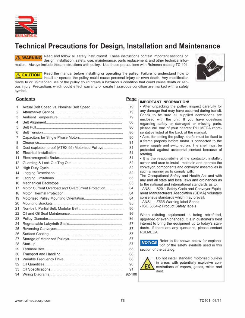
9) Dust Explosion Proof (ATEX 95) Motorized Pulleys:• The assembly, connection and sealing of the cable for dust proof motorized pulleys marked as follows
II 3 D 135°C
must be double checked to avoid any explosion in case of emergencies.• Make sure that the IP68 cable gland is properly fixed to the terminal box of the Motorized Pulley.• Make sure that the cable is properly sealed inside the cable gland. Never use a cable gland with a protection
rate lower than IP65.
10) Electrical Installation:• The equipment manufacturer (OEM) must ensure that the Motorized Pulley is not put into operation
before it is – Correctly installed,– Correctly connected to the power supply,– Correctly protected.
• A specialist must perform the electrical connection of the Motorized Pulley in accordance with electri-cal regulations. If in doubt, contact Rulmeca.
• A wiring diagram is always supplied with the Motorized Pulley. Always refer to the connection instructions andensure that the motor power and control circuits are properly connected.
• A wiring diagram is inserted into the terminal box and into the booklet accompanying each Motorized Pulley. • Standard Rulmeca Motorized Pulleys are delivered with clockwise rotation when viewed from the terminal
box end of the Motorized Pulley.• Always refer to the connection instructions and ensure that the motor is connected as required to the cor-
rect power supply.• Connect system ground wire to grounding screw located in the terminal box.• When using cable options the green/yellow wire must be connected to the system ground wire.
11) Electromagnetic Brake:• The spring-loaded electromagnetic brake is intended for use as a conveyor belt holding device and not a con-
veyor belt stopping device.
• The control circuit for the Motorized Pulley motor and brake must be designed to stop the pulley motor beforebrake clamps shut and start the pulley motor after the brake is released.
• Spring-loaded electromagnetic brakes are designed to release when power is applied to the brake coil. Thisis a “fail safe” feature. They clamp shut when brake power is removed (either during normal operation or dur-ing an emergency loss of overall system power.)
• Control circuit must be designed so that motor and brake never work against each other. The brake shouldnever be clamped shut when the motor is on except for “emergency stop” condition. The motor should neverbe powered on (including “jog” command) when the brake is clamped shut.
Technical Precautions for Design, Installation and Maintenance
NOTICE
DANGER!

www.rulmecacorp.com TC101: 08/1182
• Electromagnetic brakes are DC-powered. They are supplied with AC to DC rectifiers to be mounted in aremote panel (by others). Rectifiers must be fuse-protected.
• Motor control circuit must be designed to kill motor power in the event of loss of brake power. If this safetyprovision is not made, it is possible for pulley motor to be “powered through” a clamped brake, burning brakeand/or motor.
• A wiring diagram is supplied with every Motorized Pulley. Always ensure that motor and brake power and con-trol circuits are connected according to instructions. Wiring diagrams are available separately, at any time,upon request.
• For rectifier connection and protection instructions, refer to rectifier data sheet supplied with Motorized Pulley.
• Neglecting these instructions could cause damage to the motor and/or brake and voids product warranty.
12) Guarding and Lock Out/Tag Out:• If repair or maintenance is required, the Motorized Pulley must be disconnected from the power sup-
ply before the terminal box can be opened. Turn the electrical power off at the electrical panel board(circuit breaker or fuse box) and lock and tag the panel board door to prevent someone from turningon power while unit is being serviced. Failure to do so could result in serious electrical shock, burn,or possible death.
• During a test run, the shaft ends must be correctly fixed to the support frame, and suitable guardingmust be provided around the rotating parts for the protection of all personnel.
WARNING: DO NOT operate without guards in place. Failure to follow these instructions could result indeath or serious injury.
13) High Duty Cycle:• Rulmeca Motorized Pulleys are designed to operate either continuously or intermittently. Page 72 gives
each standard model’s maximum allowable start/stop duty cycle for intermittent operation. Operating Motor-ized Pulley above this maximum could cause motor and/or gearbox damage and voids product warranty.
• Optional Motorized Pulley designs are available to operate at higher duty cycles working with soft start devicesor appropriately programmed Variable Frequency Drives. Contact Rulmeca before designing a system tooperate at a duty cycle higher than specified in this catalog.
• Note that a conveyor control system that incorporates a “jog” command should be timed to restrict the num-ber of jogs to the maximum allowable start/stop duty cycle for each pulley model.
14) Lagging Description:• Smooth and diamond pattern lagging is available in black synthetic rubber and white synthetic rubber. Approx-
imate rubber hardness is 65 durometer +/- 5 (shore hardness A).• Standard lagging is cold-bonded to pulley shell. • Optional hot vulcanized lagging is available for high power/high torque/high temperature applications.• Oil & grease resistant synthetic rubber is also available for oily operating conditions and/or certain types of belt-
ing material. Check with belting supplier if belt/lagging material compatibility could be a problem.• Adequate Motorized Pulley heat dissipation is necessary. Lagging thickness and width greatly effect pulley
heat dissipation characteristics.• As shown in Lagging Limitations table above, certain power and belt speed combinations require that rubber lag-
ging be restricted to the outer thirds of the pulley face to improve heat dissipation. Each “partially lagged” pulleyhas a thick steel shell in the center (unlagged) third of the pulley face.
• Contact Rulmeca before applying any lagging to pulley surface to obtain thickness and width specifications andmaintain Motorized Pulley warranty coverage.
• Lagging material is a wear item and should be replaced when it wears out. Service life depends upon the appli-cation. Product warranty does not include lagging wear.
• At any time all Rulmeca Motorized Pulleys shown in this catalog must be fitted with a conveyor belt to pre-vent overheating. Motorized Pulleys fitted without a belt must be referred to Rulmeca.
Technical Precautions for Design, Installation and Maintenance
NOTICE
DANGER!
WARNING!

www.rulmecacorp.com TC101: 08/1183
15) Lagging Limitations*:
* Lagging code: “x” = standard, “o” = optional, “-” = not available.
16) Mechanical Backstops:• Motorized Pulleys fitted with mechanical backstops are used on inclined conveyors to prevent run back of the
loaded belt when power supply is off.
• The backstop is built into the Motorized Pulley and is mounted on the rotor shaft.
• If pulley is supplied with optional mechanical backstop, direction of proper rotation of pulley is indicated by analuminum arrow or plastic sticker fastened to the end housing on the terminal box (or power cord) side of thepulley. Clockwise and counterclockwise backstops are available.
• Rotation direction is to be specified when placing the order.
• Pulley rotation is specified from the point of view of a person looking at the pulley from the terminal box (orpower cord) side of the pulley.
Technical Precautions for Design, Installation and Maintenance
Motorized Pulleymodel/power and belt speed (if applicable)
RL(in)
Full Coldbonded0.118”
Full Coldbonded0.236”
Full Hotvulc.0.236”
Full Coldbonded0.315”
PartialHot vulc.0.315”
Full Coldbonded0.394”
Full Hotvulc.0.394”
PartialColdbonded0.394”
PartialHot vulc.0.394”
Full ColdCeramic/rubber0.394”
Partial ColdCeramic/rubber0.394”
Full SolidCeramic0.394”
138E< 0.5 HP x o o - - - - - - - - -0.75 & 1.0 HP <23.62 x o - - - - - - - - - -0.75 & 1.0 HP >23.62 x o - - - - - - - - - -0.75 & 1.0 HP > 120 fpm >23.62 x o o - - - - - - - - -165E< 1.0 HP x o o - - - - - - - - -1.5 & 2 HP <23.62 x o - - - - - - - - - -1.5 & 2 HP >23.62 x o o - - - - - - - - -1.5 & 2 HP > 240 fpm >23.62 x o o - - - - - - - - -220M & 220H< 2 HP - x - - - - - - - - - -3 & 4 HP <31.50 - x - - - - - - - - - -3 & 4 HP >31.50 - x - - - - - - - - - -5.5 HP <27.56 - - x - - - - - - - - -5.5 HP >27.56 - x - - - - - - - - - -7.5 HP <33.46 x - - - - - - - - - - -7.5 HP >33.46 - x - - - - - - - - - -320L - 320H< 7.5 HP - - - x - - - - - o - o10 HP <39.37 - - x - - - - - - - - o10 HP >39.37 - x - - - - - - - - - o400L - - - - - - - - - - - -400M & 400H< 15 HP - - - x - - - - - o - o20 HP < 300 fpm < 51.18 - - - - x - - - - - - o20 HP > 300 fpm > 51.18 - - - x - - - - o o - o500L & 500M x - x x x x x x500H< 25 HP - - - - - x - - - o - o30 HP - - - - - - - o x - o o40 HP - - - - - - - - - - o x630M - - - - - x - - - - o o630H30 HP - - - - - x o - - o - o40 HP < 300 fpm - - - - - - - - - x - o o40 HP > 300 fpm - - - - - - - - o x - o o50 HP - - - - - - - - - x - o o61 HP < 51.18 - - - - - - - - x - - o61 HP > 51.18 - - - - - - - o x - o o75 HP - - - - - - - - - x - o o800M61 HP - - - - - - x - o o - o o75 HP - - - - - - - - - x - o o800H75 HP < 51.18 - - - - - - - - x - o o75 HP > 51.18 - - - - - - x o x - o o100 HP < 51.18 - - - - - - - - x - o o100 HP > 51.18 - - - - - - - o x - o o122 & 150 & 180 HP - - - - - - - - x - o o1000HD - - - - - - - - - - - - x
CAUTION!

www.rulmecacorp.com TC101: 08/1184
• It is essential that the identity of each of the three phases of the power supply be determined before attachingpower supply wires to the pulley to prevent the motor from driving against the backstop. The identity of eachof the three phases of the motor is clearly labeled on the terminal board, terminal strip, or wires (in power cordtype).
• Driving the motor against the mechanical backstop may damage motor and/or backstop and voids productwarranty.
17) Motor Current Overload and Overcurrent Protection:• Motor control system must include protection against operating pulley motors in excess of Full Load Amper-
age (FLA.). The control system should also include protection against voltage spikes and excessive joggingof motors. Failing to provide adequate current overload and over current protection could stress the motorand voids product warranty.
• Electrical connection diagrams for many models are included in this catalog. Connection diagrams for all othermodels are available upon request.
• FLA data is available for all motors upon request. FLA data is also supplied on motor label for each Motorized Pul-ley.
• Electrical power, control, and protection for Motorized Pulleys must adhere to all pertinent regulations.
18) Motor Thermal Protection:• All Motorized Pulley motors are supplied with built-in thermal protection. Protection
consists of heat-sensitive, bi-metallic switches built into each motor phase winding. The switches are designedto open if motor temperature elevates to an inappropriately high level. Whether insulation class “F” or “H”, ourstandard bi-metallic switch– has a maximum current limit of 2.5 amps at 230 volts.
• These switches must be connected to a normally closed control circuit (in series with a magnetic coil/relaydevice and contactor) in order to validate product warranty.
• A motor control circuit should kill motor power if thermal switch opens. Thermal switches will automaticallyclose as motor cools. Cooling times vary with pulley model, power, and size. However, 30 to 60 minutes iscommon with most motors in an ambient temperature of 70° F.
19) Motorized Pulley Mounting Orientation:• Before installing the Motorized Pulley, ensure that the data plate information agrees with your
specification.• Rulmeca Motorized Pulleys should always be mounted so that the pulley shafts are
1. Horizontal, 2. Parallel to idler rollers, and 3. Perpendicular to the conveyor belt centerline.
• Motorized Pulleys are positioned such that the mounting brackets are located parallel or perpendi-cular to the conveyor frame. If Motorized Pulley needs to be mounted to the bottom of a horizontalbeam, contact Rulmeca.
• For Motorized Pulley types 138E to 500M “UP” is indicated with the word “UP” stamped on the pulley shaft.
• Models 138E - 500M are to be mounted as shown on the sketch below.
Technical Precautions for Design, Installation and Maintenance
UUPP
NOTICE
NOTICE
www.rulmecacorp.com TC101: 08/1185
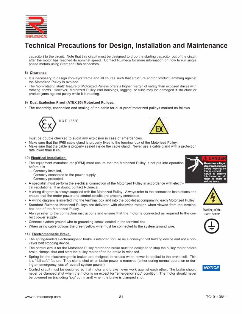
• Models 500H - 1000HD are to be mounted as shown on the sketch below.
• In case of a non-horizontal installation, of more than +/-5 degrees, consult Rulmeca.
• Installation and mounting of the Motorized Pulley in a position other than those describedabove could cause severe product damage and voids product warranty.
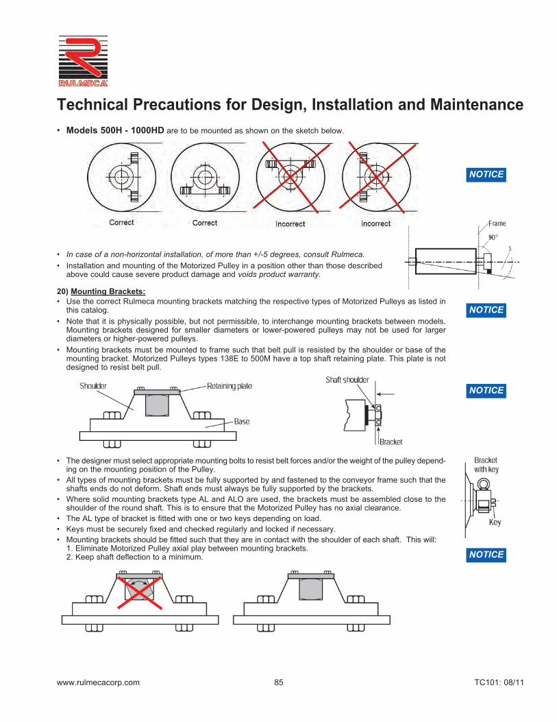
20) Mounting Brackets:• Use the correct Rulmeca mounting brackets matching the respective types of Motorized Pulleys as listed in
this catalog.
• Note that it is physically possible, but not permissible, to interchange mounting brackets between models.Mounting brackets designed for smaller diameters or lower-powered pulleys may not be used for largerdiameters or higher-powered pulleys.
• Mounting brackets must be mounted to frame such that belt pull is resisted by the shoulder or base of themounting bracket. Motorized Pulleys types 138E to 500M have a top shaft retaining plate. This plate is notdesigned to resist belt pull.
• The designer must select appropriate mounting bolts to resist belt forces and/or the weight of the pulley depend-ing on the mounting position of the Pulley.
• All types of mounting brackets must be fully supported by and fastened to the conveyor frame such that theshafts ends do not deform. Shaft ends must always be fully supported by the brackets.
• Where solid mounting brackets type AL and ALO are used, the brackets must be assembled close to theshoulder of the round shaft. This is to ensure that the Motorized Pulley has no axial clearance.
• The AL type of bracket is fitted with one or two keys depending on load.• Keys must be securely fixed and checked regularly and locked if necessary.• Mounting brackets should be fitted such that they are in contact with the shoulder of each shaft. This will:
1. Eliminate Motorized Pulley axial play between mounting brackets.2. Keep shaft deflection to a minimum.
Technical Precautions for Design, Installation and Maintenance
NOTICE
NOTICE
NOTICE
NOTICE
www.rulmecacorp.com TC101: 08/1186
• In noise-sensitive areas, the designer should use heavier gauge support structure and appropriate vibra-tion isolating material, as necessary.
• When Rulmeca Motorized Pulley mounting brackets are not used, it is essential that: 1. The mounting equipment supports at least 80% of the shaft flats. 2. The clearance between each shaft flat shoulder and its support is less than 0.030 inches.
• A Motorized Pulley with frequent reversible operations or many start/stops should be mounted with no axialclearance between the shaft flat and the brackets.
• Failing to follow these precautions could cause pulley and/or bracket damage and voids product warranty.
21) Non-Belt, Partial Belt, Modular Belt:• Special Motorized Pulley designs are available for “non-belt, V-belt, partial belt, and modular belt” applica-
tions. See “Ambient Temperature Section” above.• It is essential that each special application be designed to adequately dissipate heat from the pulley surface.
• Using a standard Motorized Pulley in one of these special applications could result in motor heat damage andvoids product warranty.
• Contact Rulmeca for assistance with these applications.
22) Oil and Oil Seal Maintenance:• All Motorized Pulleys are supplied with an appropriate quantity of oil. Oil type is specified by customer.
Oil type and quantity are given on the motor nameplate.• Standard, synthetic, food grade, low viscosity (for low temperature applications,) and high viscosity (in
noise-sensitive areas) are all available. For approved oil types and quantities, see pages 90-91.• Motorized Pulleys require periodic oil changes and are supplied with two oil fill/drain plugs in end housing.
Special “vertical mount” pulleys have four oil plugs (two in each end housing.)• Mineral oil should be changed after each 20,000 operating hours under normal operating conditions. • Synthetic oils should be changed after each 50,000 hours of normal operating condition. • Magnetic oil plug(s) should be cleaned during each oil change. A red dot plastic sticker indi-
cates the position of the magnetic oil plug.• Only approved non-conductive oil may be used in Motorized Pulleys.• Note that oil seals, regardless of oil type used, should be changed after 30,000 operating
hours. On Motorized Pulley types 320M to 1000HD oil seals may be changed without remov-ing Motorized Pulley from conveyor. Motorized Pulley standard types 138E to 320L require Pulley disassem-bly to change oil seals. Rulmeca service personal or authorized local service providers to perform this work.
• Take special precautions when changing brands of oil and types of oil because of potential oil incompatibili-ty. Contact your local oil supplier for assistance. For example, when changing from standard to synthetic oil, it is necessary to: 1. Completely drain old standard oil;2. Partially fill pulley with “Clean-Flush-Lubricate” (CFL) fluid;3. Run pulley for 20 minutes; 4. Drain CFL fluid completely; then 5. Fill pulley with appropriate amount of new synthetic oil.
• Failing to observe these oil & oil seal precautions could shorten pulley service life and voids product warranty.
• All the above instructions refer to Motorized Pulleys constantly working under full load. In case of MotorizedPulleys not working continuously under full load, the service life will increase considerably. When checkingthe oil, the cleanness of the oil is always the best guideline of– The wear and condition of the gears and bearings– Whether to change the oil immediately or possibly delay the oil change
23) Pulley Diameter:• The type and size of conveyor belt will determine the minimum allowable Motorized Pulley diameter. Using a
pulley diameter too small for the belt can cause belt de-lamination, belt splice damage and can shorten bothbelt and pulley lagging life. Contact your belting supplier before specifying a pulley diameter.
Technical Precautions for Design, Installation and Maintenance
NOTICE
NOTICE
NOTICE
www.rulmecacorp.com TC101: 08/1187
24) Regreasable Labyrinth Seals:• All Rulmeca Motorized Pulleys are hermetically sealed. Standard oil seals are designed to contain oil within the
Motorized Pulley during normal operating conditions. They are capable of withstanding an internal pressurerise that occurs as the pulley motor temperature increases.
• Optional regreasable labyrinth seals are available to protect oil seals from harsh operating or mainte-nance conditions. Each labyrinth seal provides a barrier of steel and grease to prevent ingress of dust andfluid through the oil seal.
• In abrasive operating conditions labyrinth seals should be periodically grease-purged to flush abrasive dustaway from the oil seal.
• In wet conditions, where it is common to wash down equipment with high-pressure detergent spray, labyrinthseals should be refilled with grease after each wash-down. High-pressure sprays remove grease from thelabyrinth seal, removing an important part of the barrier to fluid ingress.
• Grease should always be seen at the labyrinth gap.• If in some circumstances the re-grease frequency is high, an automatic greasing system is recommended.• Failing to perform proper labyrinth seal maintenance could shorten service life and voids product warranty.
25) Reversing Conveyors:• All Motorized Pulleys for a three-phase power supply are reversible. Mechanical backstop option is not pos-
sible for reversible conveyor applications.• The conveyor drive control system must be designed to bring the Motorized Pulley to a complete stop before
reversing conveyor belt direction.• Reversing conveyor direction without stopping the drive motor will damage motor and gearbox and voids prod-
uct warranty.
26) Surface Coating:• Motorized Pulley models 400L to 800H are supplied with a standard salt water resistant primary paint coat of
2.4 mil. For aggressive environmental conditions the Motorized Pulley should also be painted to a thicknessof 4.7 mil.
• In this case it is essential that no paint enter the gap between the shaft and the end housing to prevent shaftsealing damage.
• Motorized Pulley types 138E to 320H are supplied with powder coated end housings. The shells and shafts aretreated with anti-rust wax.
27) Storage of Motorized Pulleys:• During storage Rulmeca Motorized Pulleys must be:
– stored in a building or, as a minimum, covered by an awning.– protected against direct sunlight to insure that sealing system does not dry out.– rotated at least 180 degrees every 6 months to lubricate all internal components.
• If Motorized Pulleys must be stored longer than 1 year, they must be tested before being put into operation.Such a test should include the following.– Motor winding should be checked with an insulation tester.– Winding resistance should be checked.– Thermal protector should be checked with a continuity tester.– Pulley should be connected to the power supply and run for a minimum of 30 minutes– Pulley should then be checked to verify that there are no oil leaks – Pulley should then be checked to verify that pulley body temperature does not exceed 160° F.
• For safety reasons check that the Motorized Pulley is properly fixed to the test frame during the test.
28) Start-up:• Prior to initial start-up of Motorized Pulley:
– Verify that Motorized Pulley nameplate data matches customer specification.– Ensure electrical connections are correct.– Check that Motorized Pulley is free to rotate.
Technical Precautions for Design, Installation and Maintenance
NOTICE
NOTICE
www.rulmecacorp.com TC101: 08/1188
– Check that slack side belt tension is adequate to prevent belt slippage.– Check that belt is not over-tensioned.– Ensure that oil is present in the Motorized Pulley.
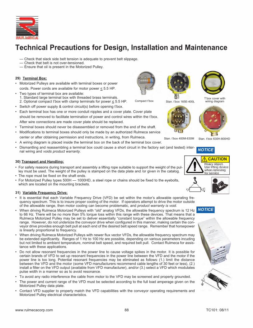
29) Terminal Box:• Motorized Pulleys are available with terminal boxes or power
cords. Power cords are available for motor power < 5.5 HP.
• Two types of terminal box are available:1. Standard large terminal box with threaded brass terminals.2. Optional compact t’box with clamp terminals for power < 5.5 HP.
• Switch off power supply & control circuit(s) before opening t’box.
• Each terminal box has one or more conduit nipples and a cover plate. Cover plate
should be removed to facilitate termination of power and control wires within the t’box.
After wire connections are made cover plate should be replaced.
• Terminal boxes should never be disassembled or removed from the end of the shaft.
• Modifications to terminal boxes should only be made by an authorized Rulmeca service
center or after obtaining permission and instructions, in writing, from Rulmeca.
• A wiring diagram is placed inside the terminal box on the back of the terminal box cover.
• Dismantling and reassembling a terminal box could cause a short circuit in the factory set (and tested) inter-nal wiring and voids product warranty.
30) Transport and Handling:• For safety reasons during transport and assembly a lifting rope suitable to support the weight of the pul-
ley must be used. The weight of the pulley is stamped on the data plate and /or given in the catalog. • The rope must be fixed on the shaft ends.• For Motorized Pulley types 500H – 1000HD, a steel rope or chains should be fixed to the eyebolts,
which are located on the mounting brackets.
31) Variable Frequency Drive:• It is essential that each Variable Frequency Drive (VFD) be set within the motor’s allowable operating fre-
quency spectrum. This is to insure proper cooling of the motor. If operators attempt to drive the motor outsideof the allowable range, then motor cooling can become problematic, and product warranty is void.
• When driving Rulmeca Motorized Pulleys with “old” analog VFDs, the allowable frequency spectrum is 12 Hzto 66 Hz. There will be no more than 5% torque loss within this range with these devices. That means that aRulmeca Motorized Pulley may be set to deliver essentially “constant torque” within the allowable frequencyrange. However, do not undersize the conveyor drive when configured in this manner, making certain the con-veyor drive provides enough belt pull at each end of the desired belt speed range. Remember that horsepoweris linearly proportional to frequency.
• When driving Rulmeca Motorized Pulleys with newer flux vector VFDs, the allowable frequency spectrum maybe extended significantly. Ranges of 1 Hz to 100 Hz are possible, depending on various parameters incudingbut not limited to ambient temperature, nominal belt speed, and required belt pull. Contact Rulmeca for assis-tance with these applications.
• Do not allow resonant frequencies in the power line to cause voltage spikes in the motor. It is possible forcertain brands of VFD to set up resonant frequencies in the power line between the VFD and the motor if thepower line is too long. Potential resonant frequencies may be eliminated as follows: (1.) limit the distancebetween the VFD and the motor (some VFD manufacturers recommend cable lengths of 30 feet or less), (2.)install a filter on the VFD output (available from VFD manufacturer), and/or (3.) select a VFD which modulatespulse width in a manner so as to avoid resonance.
• To avoid any radio interference the cable from motor to the VFD may be screened and properly grounded.
• The power and current range of the VFD must be selected according to the full load amperage given on theMotorized Pulley data plate.
• Contact VFD supplier to properly match the VFD capabilities with the conveyor operating requirements andMotorized Pulley electrical characteristics.
Technical Precautions for Design, Installation and Maintenance
NOTICE
NOTICE
CAUTION!
Compact t’box Stan. t’box 165E-400LT’box cover withwiring diagram
Stan. t’box 400M-630M Stan. t’box 630H-800HD

www.rulmecacorp.com TC101: 08/11
Taconite Plant Control Panel- “Before & After” (Minnesota—USA)Left photo shows control panel of taconite plant DC-powered variable speedconveyor control system before 1995 conversion to AC drives. Note SCR's,relay banks, and timer banks.
Right side shows control panel after conversion to AC motorized pulleyscontrolled with variable frequency drives. Elimination of SCR's and relaybanks improved reliability, simplified troubleshooting, and reduced energyloss.
Technical Precaution: The power and current range of the VFD must beselected according to the full load amperage given on the Motorized Pulleydata plate.
89
Motorized PulleysVariable Frequency Drives
Cement Plant Weigh Feeder - (Oklahoma—USA)Weigh Feeder, driven by a flux vector VFD, has 30" wide belt with 4" side-walls and is powered by a 16" diameter 5.5 HP model 400H Motorized Pul-ley with a belt speed range of 0.8 to 80 fpm. Since amp draw and Motor-ized Pulley temperature were carefully monitored during commissioning,feeders are capable of moving a wide range of material throughput (fromless than 1 tph to more than 100 tph.) VFDs automatically vary the powersupply frequency from 1 Hz to 100 Hz.
Technical Precaution: Since Motorized Pulleys cool their motors by trans-ferring heat through the pulley shell into the conveyor belt, it was essentialto verify that adequate cooling was available through the wide frequencyspectrum.
Various Limestone Quarries (Georgia—USA)Photo shows two of ten 15.75” diameter Motorized Pulleys installed 1994-1998 to automatically “choke feed” tertiary gyratory crushers. Working incombination with a VFD and an ultrasonic sensor, each Motorized Pulleydrives a 36” wide belt at a maximum speed of 120 FPM to transfer 4” minusproduct from hopper to crusher throat at 425 TPH.
Technical Precaution: Do not allow resonant frequencies in the power line tocause voltage spikes in the motor. Potential resonant frequencies may beeliminated by limiting the distance between the VFD and the motor, installinga filter on the VFD output, and/or selecting a VFD which modulates pulse widthin a manner so as to avoid resonance.
Cement Plant Dual Drive with Load-Sharing - (Oklahoma—USA)A 550 foot long reclaim tunnel conveyor, fed by six feeders, has a concavevertical curve and elevates material from beneath the storage pile 138' up tothe transfer tower. Original 75 HP drive in transfer tower was replaced bytwo 50 HP Motorized Pulleys, one on the tower and one in the tunnel, con-trolled and synchronized through the use of two flux vector VFDs.
Note : This control system insures load-sharing and provides overcurrentprotection, ramp up and ramp down, and variable belt speed, if necessary.
The dual drive configuration also eliminated belt bounce in the verticalcurve. Previously when the conveyor was started empty, it bounced up atleast 4 feet and damaged the belt and feeder support structure.