TECHNICAL DOCUMENTATION PRECAST CONCRETE SYSTEMS | …
13
Technical Documentation Loop Box V9.1.02.T.EN 01-March-2021 1 Copyright Terwa Construction Group 2005 – 2021 © | www.terwa.com TECHNICAL DOCUMENTATION PRECAST CONCRETE SYSTEMS | LOOP BOX
Transcript of TECHNICAL DOCUMENTATION PRECAST CONCRETE SYSTEMS | …

Technical Documentation Loop Box
V9.1.02.T.EN 01-March-2021
1 Copyright Terwa Construction Group 2005 – 2021 © | www.terwa.com
TECHNICAL DOCUMENTATION
PRECAST CONCRETE SYSTEMS | LOOP BOX

Technical Documentation Loop Box
V9.1.02.T.EN 01-March-2021
2 Copyright Terwa Construction Group 2005 – 2021 © | www.terwa.com
TABLE OF CONTENTS:
GENERAL PRESENTATION ....................................................................................................................................................... 3
PRODUCTION PROCESS ........................................................................................................................................................... 3
TECHNICAL DATA ...................................................................................................................................................................... 4
APPLICATION ............................................................................................................................................................................. 5
DESIGN DATA ............................................................................................................................................................................. 6
MINIMUM EDGE DISTANCE AND THE MINIMUM DISTANCE BETWEEN THE CENTRES OF LOOPS ................................ 7
REINFORCEMENTS .................................................................................................................................................................... 8
INSTALLATION INSTRUCTIONS.............................................................................................................................................. 11
FIXING TO FORMWORK ....................................................................................................................................................... 11
CASTING OF PRECAST ELEMENT ...................................................................................................................................... 12
DE-MOULDING ..................................................................................................................................................................... 12
CASTING JOINT .................................................................................................................................................................... 12
STORAGE REQUIREMENTS .................................................................................................................................................... 12
CONTACT .................................................................................................................................................................................. 13
DISCLAIMER ............................................................................................................................................................................. 13

Technical Documentation Loop Box
V9.1.02.T.EN 01-March-2021
3 Copyright Terwa Construction Group 2005 – 2021 © | www.terwa.com
GENERAL PRESENTATION
Terwa loop box – a simple and fast connection of precast concrete elements (walls and columns, etc.)
THE MAIN ADVANTAGES OF THIS SYSTEM
- Wide range of application with a small range of sizes
- Using steel cable instead of bent reinforcing bars which require unbending when mounting reduces installation time.
- Greater adaptability of concrete elements
- Rust protection – all metal components of the TLB system are galvanised.
- Reduced risk of accidents on site - without protruding reinforcement bars.
- Easily fixed to the formwork - with nails, magnet or adhesive according to the type of shuttering
- Easy installation between mesh reinforcements due to small size steel box
- The design of steel box prevents changing shape during use
SYSTEM DESCRIPTION
Terwa loop box is designed to transfer vertical shear forces, transverse shear forces, tensile forces, and their combinations in
wall to wall or wall to column connections. They are used for assembling the precast concrete elements. This system consists
of a flexible cable loop mounted inside a steel box. The wire rope loop is made from a high strength cable of which loose ends
are pressed into a steel sleeve. These systems are used for joints of walls extension, corner joints or wall-ceiling joints. In this
way, joints are made at low cost, easily and safely. We recommend using high strength, self-compacting mortar with very good
flow qualities is recommended for casting the recess of joints. The connection can be assumed as load bearing only after
grouting has reached the required strength.
Terwa loop boxes are designed to transfer predominantly static loads and can be used in indoor or outdoor condition. The
steel box and the wire cable are galvanised.
Do not use this product for lifting wall elements or other concrete elements.
PRODUCTION PROCESS
The TLB box is made of sheet metal by cutting and successive bending operations carefully checked. The cable wire is
inserted into the metal box and then pressed in a steel sleeve forming a loop. The wire rope loop is folded and placed in the
steel box which is then closed with a flexible tape to prevent ingress of grout when pouring precast elements.
The TLB wire rope loop box is made of a 0.5mm thick steel sheet.
Component Material Standard
Steel box DC01 ZE Galvanised metal sheet EN 10152
Wire cable High-strength steel wire rope -Zn – Minimum
braking load 1770 MPa EN 12385
Pressing sleeve S355J0 EN 10025
Protective tape

Technical Documentation Loop Box
V9.1.02.T.EN 01-March-2021
4 Copyright Terwa Construction Group 2005 – 2021 © | www.terwa.com
TECHNICAL DATA The box shape is designed to ensure good adherence with the concrete.
DIMENSIONS AND TOLERANCES FOR TERWA LOOP BOXES
Terwa Loop Box
Article number
SL L l b t d D
[mm] [mm] [mm] [mm] [mm] [mm] [mm]
TLB-060 63591 60 210 160 50 20 6 60
TLB-080 63592 80 210 160 50 20 6 60
TLB-100 63593 100 210 160 50 20 6 65
TLB-120 63594 120 210 160 50 20 6 70
TLB-140 63595 140 370 200 70 30 8 100
Marking Delivery condition
Technical Documentation Loop Box
V9.1.02.T.EN 01-March-2021
5 Copyright Terwa Construction Group 2005 – 2021 © | www.terwa.com
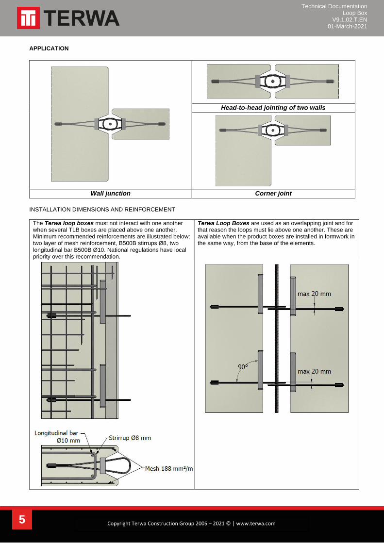
APPLICATION
Head-to-head jointing of two walls
Wall junction Corner joint
INSTALLATION DIMENSIONS AND REINFORCEMENT
The Terwa loop boxes must not interact with one another when several TLB boxes are placed above one another. Minimum recommended reinforcements are illustrated below: two layer of mesh reinforcement, B500B stirrups Ø8, two longitudinal bar B500B Ø10. National regulations have local priority over this recommendation.
Terwa Loop Boxes are used as an overlapping joint and for that reason the loops must lie above one another. These are available when the product boxes are installed in formwork in the same way, from the base of the elements.

Technical Documentation Loop Box
V9.1.02.T.EN 01-March-2021
6 Copyright Terwa Construction Group 2005 – 2021 © | www.terwa.com
DESIGN DATA
GENERAL INFORMATION
Load capacity is calculated for static loads in the case of joints with dimensions shown in the picture below. The calculations
take no account of cracks and deformations of the joints. Terwa Loop Boxes are designed to connect walls or columns with
minimum concrete strength 25/30 MPa or higher and the grouting material must have at least the same compressive strength
as the precast concrete element.
The length of wire rope loop and the recess dimensions must be matched to ensure a suitable overlapping of the wire loops
and to guarantee full carrying capacity. There should be enough space in the casting recess for the loops in the unfolded state
without hitting.
Terwa Loop Box Total recess dimension
a
Overlap b
Recess depth c
Wall thickness tmin
Type [mm] [mm] [mm] [mm]
TLB-060 80 40 30 80
TLB-080 100 60 40 80
TLB-100 120 80 50 120
TLB-120 140 100 60 120
TLB-140 160 120 70 150
For selecting the the suitable type of Terwa Loop Box, the following aspects must be considered:
- Wall thickness - Geometry of the joint - Load-bearing capacity.
Technical Documentation Loop Box
V9.1.02.T.EN 01-March-2021
7 Copyright Terwa Construction Group 2005 – 2021 © | www.terwa.com
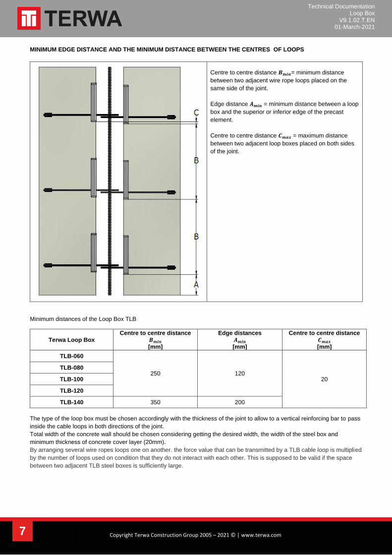
MINIMUM EDGE DISTANCE AND THE MINIMUM DISTANCE BETWEEN THE CENTRES OF LOOPS
Centre to centre distance 𝑩𝒎𝒊𝒏= minimum distance
between two adjacent wire rope loops placed on the
same side of the joint.
Edge distance 𝑨𝒎𝒊𝒏 = minimum distance between a loop
box and the superior or inferior edge of the precast
element.
Centre to centre distance 𝑪𝒎𝒂𝒙 = maximum distance
between two adjacent loop boxes placed on both sides
of the joint.
Minimum distances of the Loop Box TLB
Terwa Loop Box Centre to centre distance
𝑩𝒎𝒊𝒏 [mm]
Edge distances 𝑨𝒎𝒊𝒏 [mm]
Centre to centre distance 𝑪𝒎𝒂𝒙 [mm]
TLB-060
250 120 20
TLB-080
TLB-100
TLB-120
TLB-140 350 200
The type of the loop box must be chosen accordingly with the thickness of the joint to allow to a vertical reinforcing bar to pass
inside the cable loops in both directions of the joint.
Total width of the concrete wall should be chosen considering getting the desired width, the width of the steel box and
minimum thickness of concrete cover layer (20mm).
By arranging several wire ropes loops one on another. the force value that can be transmitted by a TLB cable loop is multiplied
by the number of loops used on condition that they do not interact with each other. This is supposed to be valid if the space
between two adjacent TLB steel boxes is sufficiently large.

Technical Documentation Loop Box
V9.1.02.T.EN 01-March-2021
8 Copyright Terwa Construction Group 2005 – 2021 © | www.terwa.com
REINFORCEMENTS A vertical reinforcement bar made of B500B called lock bar is installed in the centre joint. This bar is designed to take the
traction forces that occur in concrete joint.
Recommended dimensions for internal reinforcement
Terwa Loop Box Diameter of reinforcing bar
[mm]
TLB-080
12 TLB-100
TLB-120
TLB-140 16
The precast concrete elements must be reinforced in accordance with project requirements. TLB loop boxes provide good
anchorage by making a sufficient overlapping of cable loops with precast elements reinforcements. We recommend using U-
shaped stirrup installed in the area of each wire loop.
TLB system must be installed so that the loop axes lie symmetrically about the axis cross-section, to ensure that all loops are
evenly loaded.
Resistances Resistances of joints with the Terwa loop box are defined according to loop spacing and compressive strength of concrete grout in the joint. Resistances are determinate by a design concept that refers to the standards EN 1990-1, EN 1992-1-1 (2004), EN 1992-1-2 (2004). Resistance of the Terwa loop box joint for combined forces may be calculated according to equation: 𝑽𝑬𝒅𝑽𝑹𝒅
+𝑵𝑬𝒅𝑵𝑹𝒅
+𝑭𝑬𝒅𝑭𝑹𝒅
≤ 𝟏
Where:
- 𝑽𝑬𝒅 – design value of longitudinal shear force
- 𝑽𝑹𝒅 – design value of resistance for longitudinal shear force
- 𝑵𝑬𝒅 – design value of transverse shear force
- 𝑵𝑹𝒅 – design value of resistance for transverse shear force
- 𝑭𝑬𝒅 – design value of tensile force
- 𝑭𝑹𝒅 – design value of resistance for tensile force

Technical Documentation Loop Box
V9.1.02.T.EN 01-March-2021
9 Copyright Terwa Construction Group 2005 – 2021 © | www.terwa.com
Calculation model
Vertical shear load transfer model
- Longitudinal shear forces 𝑽𝑬𝒅 combined
with tensile forces 𝑭𝑬𝒅
Transverse shear load transfer model
- Transverse shear forces 𝑵𝑬𝒅 combined
with Tensile forces 𝑭𝑬𝒅
Important! It is not possible to transfer any bending moments with the Terwa loop box connection.

Technical Documentation Loop Box
V9.1.02.T.EN 01-March-2021
10 Copyright Terwa Construction Group 2005 – 2021 © | www.terwa.com
Tensile forces - design value in one pair of wire rope loops
Terwa Loop Box Tensile resistance 𝑭𝑹𝒅 in one pair of wire rope loops [kN/pair of boxes]
C25/30 C30/37 C35/45 C40/50 C45/55
TLB-060
11.40 12.63 13.87 15.83 17.10 TLB-080
TLB-100
TLB-120
TLB-140 15.96 17.70 19.41 22.08 23.94
Transverse shear forces - design value in one pair of loop boxes
Terwa Loop Box Transverse shear resistance 𝑵𝑹𝒅 in one pair of wire rope loops [kN/pair of boxes]
C25/30 C30/37 C35/45 C40/50 C45/55
TLB-060
2.99 3.27 3.55 3.81 4.03 TLB-080
TLB-100
TLB-120
TLB-140 3.70 4.10 4.40 4.80 5.10
Longitudinal shear forces - design value in one pair of loop boxes
Terwa Loop Box Longitudinal shear resistance 𝑽𝑹𝒅 in one pair of wire rope loops [kN/pair of boxes]
C25/30 C30/37 C35/45 C40/50 C45/55
TLB-060
14.20 15.75 17.30 19.70 21.40 TLB-080
TLB-100
TLB-120
TLB-140 27.30 30.22 33.20 37.72 40.90

Technical Documentation Loop Box
V9.1.02.T.EN 01-March-2021
11 Copyright Terwa Construction Group 2005 – 2021 © | www.terwa.com
INSTALLATION INSTRUCTIONS FIXING TO FORMWORK The main steps to follow before casting concrete precast elements:
- The wire loop of the TLB system must be in good condition and no rust or wire breakages.
- Loop box conforms to the technical documentation and placement is correct.
- TLB system is firmly fixed to formwork.
- Additional reinforcements (stirrups) are installed properly.
Wire rope damage
Rust Broken wire
The boxes must be nailed into place starting from the lowest
point of the element. That arrangement must be same on
both sides of the joint.
Fixing the Terwa loop box Removing the adhesive tape after demoulding
Straightening of cable loops Correct installation of the wire loop perpendicular to wall
joint

Technical Documentation Loop Box
V9.1.02.T.EN 01-March-2021
12 Copyright Terwa Construction Group 2005 – 2021 © | www.terwa.com
In the front side of the TLB wire loop box, two or three holes are punched. These are used for fixing with nails on wooden
formwork. The sheet box containing the wire loops are closed with strong and flexible tape to prevent entry of concrete when
pouring precast wall.
Formwork fixing for the loop box must be firm so that its movement does not appear when pouring concrete. TLB system is
fixed to metal or plastic formwork using magnets or adhesives. In this case, the contact surface of the formwork with box
flange must be smooth and well degreased before use. Otherwise, they can detach and can move when pouring concrete or
during compaction. Concrete near the cable loops should be carefully compacted. Loop boxes must not be vibrated.
The shape of the joint cavity is designed according to the type of application and the type of components used. Mesh
reinforcements of the walls should continue to the prominences of the panel edge to avoid breaking of the edges at de-
moulding. A slight taper and a good lubrication of the formwork can ease the process of de-moulding.
When fixing the TLB box to the formwork,proper placement of the cable loop must be ensured so that it is as straight as
possible between mesh reinforcement.
CASTING OF PRECAST ELEMENT
The main steps to follow before casting precast elements:
- The TLB cable loop must remain in correct position
DE-MOULDING
The main steps to follow casting precast elements:
- The position of TLB cable loops is according to design drawings.
- The cover tape of sheet box is removed after hardening of the concrete.
After removing formwork, the flexible cover tape is removed, and the wire rope loop can be easily folded out. Wire rope loops
must remain in a plane perpendicular to the front of steel box to ensure a proper and controlled overlap of opposite cable
loops. At this moment, the precast concrete element is ready for final assembly on site.
CASTING JOINT
At final assembly, after placing precast element to the required position, the bar assembly with the diameter shown in upper
table is inserted from above to down through all the cable loops. The installed precast wall must always be secured by
temporary bracing. To ensure a correct transfer of forces, the joint must be correctly and completely filled with concrete. At the
same time, proper compression of the concrete must be ensured. The concrete used in the joint should have a consistency to
ensure adequate flow in the intermediate spaces inside steel boxes. We recommended using ready mixed casting kits. If the
self-compacting mixtures are used, vibration of concrete is no longer necessary.
STORAGE REQUIREMENTS
Terwa loop boxes must be stored and protected in dry conditions, under a roof. Large temperature variations, snow, ice,
humidity, or saltwater impact may cause damage to wire rope and shorten the service life.

Technical Documentation Loop Box
V9.1.02.T.EN 01-March-2021
13 Copyright Terwa Construction Group 2005 – 2021 © | www.terwa.com
CONTACT
TERWA is the global supplier for precast and construction solutions with multiple offices around the world. With all our staff, partners and agents, we are happy to provide all construction and precast companies who work in the building industry with full service and 100% support. TERWA CONSTRUCTION GROUP
Terwa Construction Netherlands (HQ) Global Sales & Distribution
Kamerlingh Onneslaan 1-3 3401 MZ IJsselstein The Netherlands T +31-(0)30 699 13 29 F +31-(0)30 220 10 77 E [email protected]
Terwa Construction Central East Europe Sales & Distribution
Strada Sânzienei 507075 Ghimbav Romania T +40 372 611 576 E [email protected]
Terwa Construction Poland Sales & Distribution
Ul. Cicha 5 lok. 4 00-353 Warszawa Poland E [email protected]
Terwa Construction India & Middle East Sales & Distribution
India T +91 89 687 000 41 E [email protected]
Terwa Construction China Sales & distribution
5F 504, No. 101 Chuanchang road PRC, 200032, Shanghai China E [email protected]
ALL SPECIFICATIONS CAN BE CHANGED WITHOUT PRIOR NOTICE. DISCLAIMER Terwa B.V. is not liable for deviations due to wear of the products it has delivered. Neither is Terwa B.V. liable for damage due to inaccurate and/or improper handling and use of the products it has delivered and/or use of same for purposes other than those intended. Terwa B.V.’s responsibility is furthermore limited in accordance with article 13 of the “Metaalunie” conditions, which are applicable for all Terwa B.V. deliveries. The user is responsible for ensuring compliance with all applicable copyright laws. Without limiting the rights under copyright, no part of this documentation may be reproduced, stored in or introduced into a retrieval system, or transmitted in any form or by any means (electronic, mechanical, photocopying, recording, or otherwise), or for any purpose, without the express written permission of Terwa B.V.


![SECTION 034500 - PRECAST ARCHITECTURAL CONCRETE · Architectural precast concrete cladding [and load-bearing] units. ... PRECAST ARCHITECTURAL CONCRETE 034500 ... Architectural Cladding](https://static.fdocuments.net/doc/165x107/5ae006067f8b9a1c248cb77e/section-034500-precast-architectural-concrete-precast-concrete-cladding-and-load-bearing.jpg)