TECHNICAL DATA - U-IDEE · technical data i-dream drills dream drills-general dream drills-inox...
15
TECHNICAL DATA TECHNISCHE DATEN Being the best through innovation DRILLS
Transcript of TECHNICAL DATA - U-IDEE · technical data i-dream drills dream drills-general dream drills-inox...
TECHNICAL DATATECHNISCHE DATEN
Being the best through innovationDRILLS
!"#$%&'()&"&*$$' !&+!'+&$!',"-$./$$ &'($$$$ !$

1Twist Drill with parallel shankSpiralbohrer mit Zylinderschaft
2Twist Drill with taper shank Spiralbohrer mit kegelschaft
3General dimensions of morse taper shanks Toleranzen des kegelschaftes
330U phone:+82-32-526-0909, fax:+82-32-526-4373, www.yg1.kr, E-mail:[email protected]
TECHNICAL
DATA
i-DREAM DRILLS
DREAMDRILLS-GENERAL
DREAMDRILLS-INOX
DREAMDRILLS-ALU
DREAMDRILLS-CFRP
DREAMDRILLS-MQL TYPE
DREAMDRILLSfor HARDENEDSTEELS
GENERALCARBIDEDRILLS
NC-SPOTTINGDRILLS
CENTERDRILLS
MULTI-1DRILLS
HPD DRILLS
GOLD-PDRILLS
STRAIGHTSHANKDRILLS
TAPERSHANKDRILLS
NC-SPOTTINGDRILLS
CENTERDRILLS
SPADEDRILLS
TECHNICALDATA
CARBIDE
HSS
Driving tangMitnehmer
Flat tangAustreiblappen
Taper shankKegelschaft
Recess(space for inscription)Einstich (Beschriftungsstelle)
Cutting portionSchneidteil
Point lengthSpitzenlänge
dD
rill
dia
mete
rB
oh
rerd
urc
hm
esse
r
Recess lengthEinstichlänge
Shank diameterSchaftdurchmesser
Parallel shankZylinderschaft
Shank lengthSchaftlänge
Taper lengthKegellänge
B
H
F
õ8£
· 2
E G
D
ADiam.
C
Flute lengthSpannutlänge
Overall lengthGesamtlänge
Length of cut sectionSchneidlänge
No.1
No.2
No.3
No.4
No.5
No.6
12.065
17.780
23.825
31.267
44.399
63.348
9
14
19.1
25.2
36.5
52.4
5.2
6.3
7.9
11.9
15.9
19
12.2
18.0
24.1
31.6
44.7
63.8
62
75
94
117.5
149.5
210
13.5
16
20
24
29
40
3.5
5
5
6.5
6.5
8
8.7
13.5
18.5
24.5
35.7
51
1£25‹43›
1£25‹50›
1£26‹16›
1£29‹15›
1£30‹26›
1£29‹36›
·
2H(max.)
mmG
mmF(max.)
mmE
mmD
mmC(h13)
mmB
mmA
mmMorse Taper ShankMorsekegelschaft
!"#$%&'()&"&*$$' !&+!'+&$!',"-$./$$ && $$$$ !$

331Uphone:+82-32-526-0909, fax:+82-32-526-4373, www.yg1.kr, E-mail:[email protected]
TECHNICAL
DATAi-DREAM DRILLS
DREAMDRILLS-GENERAL
DREAMDRILLS-INOX
DREAMDRILLS-ALU
DREAMDRILLS-CFRP
DREAMDRILLS-MQL TYPE
DREAMDRILLSfor HARDENEDSTEELS
GENERALCARBIDEDRILLS
NC-SPOTTINGDRILLS
CENTERDRILLS
MULTI-1DRILLS
HPD DRILLS
GOLD-PDRILLS
STRAIGHTSHANKDRILLS
TAPERSHANKDRILLS
NC-SPOTTINGDRILLS
CENTERDRILLS
SPADEDRILLS
TECHNICALDATA
CARBIDE
HSS
4Cutting portionSchneidteil
Ú= Point angle (sigma) Spitzenwinkel (Sigma)
◊ = Chisel edge angle (psi) Querschneidenwinkel(Psi)
JIn the context of cutting technology, land width b·is the body clearance land width which is to be by b f·n, see DIN 6581.Die Fasenbreite b
·ist bei zerspanungstechnischen Betrachtungen die Fasenbreite der Nebenfreifläche und mit b f·n zu bezeichnen, siehe DIN 6581.
·x = Side clearance angle (alpha) Seitenfreiwinkel (Alpa)
·xe= Effective side clearance angle Wirk-Seitenfreiwinkel
‚x = Side wedge angle (beta) Seitenkeilwinkel (Beta)
„x = Front rake angle (gamma) Seitenspanwinkel (Gamma)
„xe= Working front rake angle Wirk-Seitenspanwinkel
Á = Resultant cutting speed angle (eta) Wirkrichtungswinkel (Eta)
Clearance angle ·, wedge angle ‚and rake angle „are measured in the tool orthogonal plane. For details, see DIN 6581,
definitions of metal-cutting technology; geometry at the tool edge.
Freiwinkel ·, keilwinkel ‚und Spanwinkel „werden in der keilme‚ebene gemessen.
Einzelheiten siehe DIN 6581, Begriffe der Zerspantechnik; Geometrie am Schneidkeil des Werkzeuges.
The corner has been adopted as the observed edge point. Als betrachteter Schneidenpunkt ist die Schneidenebene gewählt.
FlankHaupt-freifläche
CornerSchneidenecke
FaceSpanfläche
Cutting lipHauptschneide
Margin width b·*)Fasenbreite b·*)
Flute landStegbreite
Leading edge of landNebenschneide
MarginFase
Chisel edgeQuerschneide Heel deburred
Rückenkante entgratet
Chamferedgebrochen
Radiusedgerundet
Detail XEinzelheit X
HeelRückenkante
FluteSpannut
X
Web thickness k
Body clearanceNeben-freifläche (Rücken)
Bod
y cl
eara
nce
diam
eter
Rüc
ken-
druc
hmes
ser
◊
Ú
dD
rill
dia
mete
rB
oh
rerd
urc
hm
esse
r
Feed directionVorschubrichtung
CornerSchneidenecke
Resultant cutting speed angle Wirkrichtungswinkel
Cutting directionSchnittrichtung
Direction of cutting motionWirkrichtung
Cutting travel per revolution = d !Schnittweg je Umdrehung = d !
Feed sVorschub s
"
!
"
#
$
$
!
5Angle at the cutting edges Winkel an den Schneiden
!"#$%&'()&"&*$$' !&+!'+&$!',"-$./$$ &&!$$$$ !$
332U phone:+82-32-526-0909, fax:+82-32-526-4373, www.yg1.kr, E-mail:[email protected]
TECHNICAL
DATA
i-DREAM DRILLS
DREAMDRILLS-GENERAL
DREAMDRILLS-INOX
DREAMDRILLS-ALU
DREAMDRILLS-CFRP
DREAMDRILLS-MQL TYPE
DREAMDRILLSfor HARDENEDSTEELS
GENERALCARBIDEDRILLS
NC-SPOTTINGDRILLS
CENTERDRILLS
MULTI-1DRILLS
HPD DRILLS
GOLD-PDRILLS
STRAIGHTSHANKDRILLS
TAPERSHANKDRILLS
NC-SPOTTINGDRILLS
CENTERDRILLS
SPADEDRILLS
TECHNICALDATA
CARBIDE
HSS
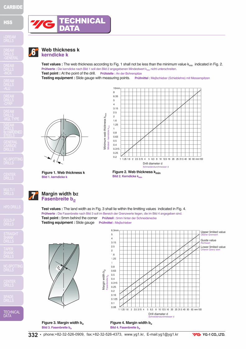
6Web thickness kkerndicke k
7 Margin width b·Fasenbreite b·
Test values : The web thickness according to Fig. 1 shall not be less than the minimum value kmin indicated in Fig. 2.
Prüfwerte : Die kerndicke nach Bild 1 soll den Bild 2 angegebenen Mindestwert kmin nicht unterschreiten.
Test point : At the point of the drill. Prüfstelle : An der Bohrerspitze
Testing equipment : Slide gauge with measuring points. Prüfmittel : Me‚schieber (Schieblehre) mit Messerspitzen
Test values : The land width as in Fig. 3 shall lie within the limitting values indicated in Fig. 4.
Prüfwerte : Die Fasenbreite nach Bild 3 soll im Bereich der Grenzwerte liegen, die im Bild 4 angegeben sind.
Test point : 5mm behind the corner Prüfstell : 5mm hinter der Schneidenecke
Testing equipment : Slide gauge Prüfmittel : Me‚schieber
Figure 1. Web thickness kBild 1. kerndicke k
Figure 2. Web thickness kminBild 2. Kerndicke kmin
Upper limited valueOberer Grenwert
Guide valueRichtwert
Lower limited valueUnterer Grenz wert
Min
imu
m w
eb
th
ickn
ess k
min
Min
de
st
- ke
rnd
icke
km
in
Drill diameter dSchneidendurchmesser d
Drill diameter dSchneidendurchmesser d
10mm
8
6.35
5
4
3.15
2.5
2
1.6
1.25
1
0.8
0.63
0.5
0.4
0.315
0.25
0.21 1.25 1.6 2 2.5 3.15 4 5 6.3 8 10 12.5 16 20 25 31.5 40 50 63 mm 100k
Figure 3. Margin width b
Bild 3. Fasenbreite b
Figure 4. Margin width b
Bild 4. Fasenbreite b
Ma
rgin
wid
th b·
Fa
se
nb
reite
b·
6.3mm
5
4
3.15
2.5
2
1.6
1.25
1
0.8
0.63
0.5
0.4
0.315
0.25
0.2
0.16
0.125
0.1
0.081 1.25 1.6 2 2.5 3.15 4 5 6.3 8 10 12.5 16 20 25 31.5 40 50 63 mm 100
b
!"#$%&'()&"&*$$' !&+!'+&$!',"-$./$$ &&'$$$$ !
333Uphone:+82-32-526-0909, fax:+82-32-526-4373, www.yg1.kr, E-mail:[email protected]
TECHNICAL
DATAi-DREAM DRILLS
DREAMDRILLS-GENERAL
DREAMDRILLS-INOX
DREAMDRILLS-ALU
DREAMDRILLS-CFRP
DREAMDRILLS-MQL TYPE
DREAMDRILLSfor HARDENEDSTEELS
GENERALCARBIDEDRILLS
NC-SPOTTINGDRILLS
CENTERDRILLS
MULTI-1DRILLS
HPD DRILLS
GOLD-PDRILLS
STRAIGHTSHANKDRILLS
TAPERSHANKDRILLS
NC-SPOTTINGDRILLS
CENTERDRILLS
SPADEDRILLS
TECHNICALDATA
CARBIDE
HSS
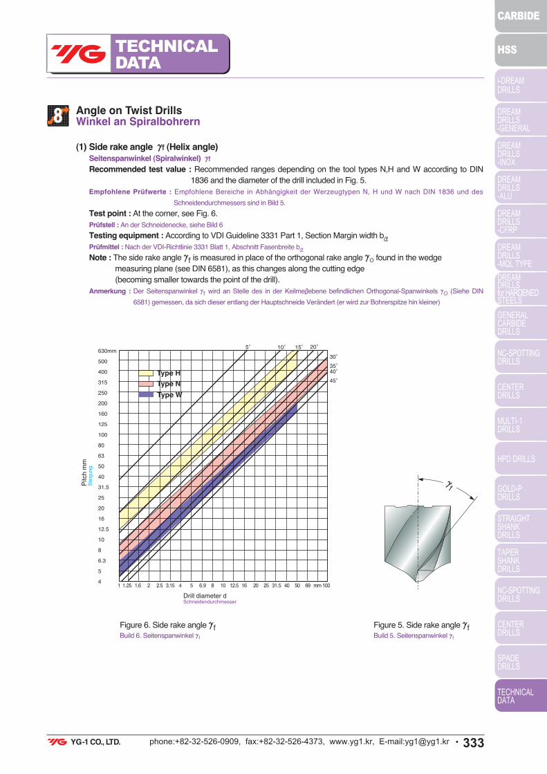
8Angle on Twist DrillsWinkel an Spiralbohrern
(1) Side rake angle „f (Helix angle)
Seitenspanwinkel (Spiralwinkel) „f
Recommended test value : Recommended ranges depending on the tool types N,H and W according to DIN
1836 and the diameter of the drill included in Fig. 5.
Empfohlene Prüfwerte : Empfohlene Bereiche in Abhängigkeit der Werzeugtypen N, H und W nach DIN 1836 und des
Schneidendurchmessers sind in Bild 5.
Test point : At the corner, see Fig. 6.
Prüfstell : An der Schneidenecke, siehe Bild 6
Testing equipment : According to VDI Guideline 3331 Part 1, Section Margin width b·
Prüfmittel : Nach der VDI-Richtlinie 3331 Blatt 1, Abschnitt Fasenbreite b·
Note : The side rake angle „f is measured in place of the orthogonal rake angle „O found in the wedge
measuring plane (see DIN 6581), as this changes along the cutting edge
(becoming smaller towards the point of the drill).
Anmerkung : Der Seitenspanwinkel „f wird an Stelle des in der Keilme‚ebene befindlichen Orthogonal-Spanwinkels „O (Siehe DIN
6581) gemessen, da sich dieser entlang der Hauptschneide Verändert (er wird zur Bohrerspitze hin kleiner)
Figure 6. Side rake angle „fBuild 6. Seitenspanwinkel „f
Figure 5. Side rake angle „fBuild 5. Seitenspanwinkel „f
„f
Pitch
mm
Ste
igu
ng
630mm
500
400
315
250
200
160
125
100
80
63
50
40
31.5
25
20
16
12.5
10
8
6.3
5
4
5£ 10£ 15£ 20£
30£
35£40£
45£
1 1.25 1.6 2 2.5 3.15 4 5 6.9 8 10 12.5 16 20 25 31.5 40 50 69 mm 100
Drill diameter dSchneidendurchmesser
!"#$%&'()&"&*$$' !&+!'+&$!',"-$./$$ &&&$$$$ !$

334U phone:+82-32-526-0909, fax:+82-32-526-4373, www.yg1.kr, E-mail:[email protected]
TECHNICAL
DATA
i-DREAM DRILLS
DREAMDRILLS-GENERAL
DREAMDRILLS-INOX
DREAMDRILLS-ALU
DREAMDRILLS-CFRP
DREAMDRILLS-MQL TYPE
DREAMDRILLSfor HARDENEDSTEELS
GENERALCARBIDEDRILLS
NC-SPOTTINGDRILLS
CENTERDRILLS
MULTI-1DRILLS
HPD DRILLS
GOLD-PDRILLS
STRAIGHTSHANKDRILLS
TAPERSHANKDRILLS
NC-SPOTTINGDRILLS
CENTERDRILLS
SPADEDRILLS
TECHNICALDATA
CARBIDE
HSS
9Resharpening Twist Drills Nachschleifen von Spiralbohrern
(2) Point angle Ú
Spitzenwinkel Ú
Test value : Usual execution for tool types N and H : Ú=118£, for tool type W : Ú=130£
Prüfwerte : Regelausführung bei Werkzeugtyp N und H : Ú=118£
bei Werkzeugtyp W : Ú=130£
Test point : At the cutting , see Fig. 7.Prüfstelle : An den Hauptschneiden, siehe Bild 7.
Testing equipment : According to VDI Guideline 3331 Part 1, Section Margin width b
·.
Prüfmittel : Nach der VDI-Richtlinie 3331 Blatt 1, Abschnitt Fasenbreite b·.
(1) Drills are worn off irregularly. It should be sharpened prior to developing into excessive wear.
Unregelmäßiger Verschleiß von Bohrern. Bohrer soll vor übermäßigern Verschleiß nachgeschilffen werden.
(2) Resharpening (Nachschleifen)
Á Grind the correct point angle to suit your application.(figure 8)Den für Ihre Anwendung passenden korrekten Spltzenwinkel schleifen (Bild 8)
Ë Check that both cutting lips have the same angle. On a 130£point, each lip should be 65£toward the axis. Thepoint must be on center, i.e., the chisel edge must produce cutting lips of equal length.(figure 8) Überprüfen, dass beide Hauptschneiden den gleichen Winkel haben. Bei einem 130£Spitzenwinkel, sollte jede Hauptschneide 65£
haben (Bild 8)
È Grind Primary relief and Secondary clearance.(figure 9)Primärer Hinterschliff und Sekundärer Freiwinkel (Bild 9)
Í Grind web thinning. (figure 10)Den ausgespitzten Kern schleifen (Bild 10)
Figure 8Bild 8
Figure 9Bild 9
Figure 10Bild 10
Primaryreliefangle
Secondaryclearance
angle
Pointangle
=
=
=
=
Web thinning
Figure 7. Point angle ÚBild 7. Spitzenwinkel Ú
Ú
!"#$%&'()&"&*$$' !&+!'+&$!',"-$./$$ &&"$$$$ !$

335Uphone:+82-32-526-0909, fax:+82-32-526-4373, www.yg1.kr, E-mail:[email protected]
TECHNICAL
DATAi-DREAM DRILLS
DREAMDRILLS-GENERAL
DREAMDRILLS-INOX
DREAMDRILLS-ALU
DREAMDRILLS-CFRP
DREAMDRILLS-MQL TYPE
DREAMDRILLSfor HARDENEDSTEELS
GENERALCARBIDEDRILLS
NC-SPOTTINGDRILLS
CENTERDRILLS
MULTI-1DRILLS
HPD DRILLS
GOLD-PDRILLS
STRAIGHTSHANKDRILLS
TAPERSHANKDRILLS
NC-SPOTTINGDRILLS
CENTERDRILLS
SPADEDRILLS
TECHNICALDATA
CARBIDE
HSS
10Web thinning Kegelmantelschliff
(1) Without thinning
Normalanschliff
Suitable for drill of general purpose.
Thanks to thin web thickness, web thinning is not needed.
This without web thinning type is applied to design of drills
for mild steels, alloy steels, cast iron, stainless steels,
titanium, inconel, etc. and conventional cutting conditons.
Zum Bohren für allgemeine Zwecke.
Dank dünner Kerndicke, ist Kegelmantelanschliff nicht nötig.
Geeignet für Stahl, Stahl-Legierungen, Gusseisen, Edeistahl, Tian, Inconel usw, und für konventionelle Schneidbedingungen
(2) Type C thinning (DIN1412 FORM C, SPLIT POINT)
DiN 1412 Form C kegelmantelanschliff mit Kreuzanschliff
Because Split point enables good centering when drilling
and breaks the chips, chip removals are easy.
Suitable for drill design in high hardened tough materials, i.e,
heat treated steels, titanium alloys, stainless steels, incoroy
inconel, nimonic, etc.
Da Kreuzanschliff gute Zentrierung und Spanbruch während des
Bohrens ermöglicht, wird die Spanentfernung erleichtert.
Geeignet für zähe Werkstücke oder Werkstücke mit hoher Härte, z.B. hitzebehandelten Stahl, Titan-Legierungen, Edelstahl, Incoroy
Inconel, Nimonic usw.
(3) Type R thinning (HELICAL THINNING)
Form R Kegelmantelanschliff (Spiralanschliff)
Helical thinning ensures to frequent chip breaking and
removal. The different direction force of cutting edges and
helical thinning parts enable that chips curl, break and
remove through the flutes. In addition, helical thinning
makes the chip room up to center, remove the chisel and
enables good centering
Häufiger Spanbruch und Spanentfernung durch Spiralanschliff, es wird
ausreichend Raum für Späne geschaffen, und gute Zentrierung ist möglich.
(4) Type A thinning (DIN1412 FORM A)
DIN 1412 Form A Kegelmantelanschliff mit ausgespitzer Querschneide
A type thinnings makes thin chisel, good chip removal and
favorable centering.
This type is the easiest type to grind the thinning. In narrow
web and wide fluted drills, keeping of the rigidity and smooth
chip removal are possible.
Diese Form hat eine dünne Querschneide, dadurch ist gute
Spanentfernung und Zentrierung möglich.
Der Kegelmantelschliff ist bei dieser Form am einfachsten
nachszuchleifen, Ein enger Kern und breite Schneiden erhalten die Stabilität.
!"#$%&'()&"&*$$' !&+!'+&$!',"-$./$$ &&0$$$$ !$

336U phone:+82-32-526-0909, fax:+82-32-526-4373, www.yg1.kr, E-mail:[email protected]
TECHNICAL
DATA
i-DREAM DRILLS
DREAMDRILLS-GENERAL
DREAMDRILLS-INOX
DREAMDRILLS-ALU
DREAMDRILLS-CFRP
DREAMDRILLS-MQL TYPE
DREAMDRILLSfor HARDENEDSTEELS
GENERALCARBIDEDRILLS
NC-SPOTTINGDRILLS
CENTERDRILLS
MULTI-1DRILLS
HPD DRILLS
GOLD-PDRILLS
STRAIGHTSHANKDRILLS
TAPERSHANKDRILLS
NC-SPOTTINGDRILLS
CENTERDRILLS
SPADEDRILLS
TECHNICALDATA
CARBIDE
HSS
11Surface Finishes for high speed steels Twist Drills Oberflächenbeschaffenbeit von HSS-Spiralbohrern
(1) Bright Finish Helle Beschaffenheit
Drills with a bright finish are without surface treatment and ground condition.
Especially bright finished drills are used in machining of non ferrous materials.
Ohne Oberflächenbehandlung, geeignet zum Bearbeiten von Nichteisen Materiallen.
(2) Coloring (Gold color) Farbe (Bernstein)
The coloring is a thin oxide layer formed on the tool surfaces. Dies ist eine dünne Oxidschicht.
This is often applied to cobalt high speed steels twist drills. Geeignet für Kobalt-HSS-Spiralbohrer.
(3) Steam Tempered (black oxide finish) Dampfoxidierte Ausführung
This is a black oxide layer 1-2≠ formed on the tool surfaces.
Steam Tempered treated drill is the result of a steam tempering operation. Because the oxide layer retains some
coolant on the tool surface, and aids chip flow, helps to dissipate heat, steam homo treated drills are
recommended for ferrous applications.
Eine schwarze Oxidschicht 1-2 ≠.
Da die Oxidschicht Kühlmitteleigenschaften auf der Werkzeugoberfläche beinhaltet und den Spanfluss verbessert und die Hitze verteilt,
sind diese Bohrer für die Bearbeitung von Metal-Werkstücken empfohlen.
(5) Type B thinning (DIN1412 FORM B)
DIN 1412 Form B Kegelmantelanschliff mit ausgespitzer Querschneide
In case of work materials with low cutting resistance and
good chip removal, i.e., cast iron, aluminum, plastic etc., B
type thinning is suitable.
Especially when drills for high hardended steels are
designed, this type is applied to decrease rake angle and
avoid chipping of cutting lips.
Geeignet für Werkstücke mit geringern Schneidwiderstand und guter
Spanentfernung, z.B. Gusseisen, Aluminium, Plastik usw.
Diese Form wird besonders dann angewendet, wenn der Bohrer für Stähle mit hoher Härte produziert wurde, da dadurch der
Seitenspanwinkel verkleinert wird und Brüche an der Schneidkante vermieden werden.
(6) Type D thinning (DIN1412 FORM D)
DIN 1412 Form D Kegelmantelanschliff mit ausgespitzern Kern
Grey cast iron thinning; bevelling of external edges
strengthens the cutting edge.
Used for medium to high grey cast iron hardness and for
abrasives.
GG-Anschliff; Fasen auf dem Steg verstärken die Schneidkante.
Geeignet für medium bis hohe Härte GG und für abrasive Materialien.
(7) Type E thinning (DIN1412 FORM E)
DIN 1412 Form E Zentrumspitze
Center drill bit thinning; ensures optimal center drilling and
does not leave burs in through holes.
As the bit and cutting edges are delicate, this bit should be
used far drilling thin sheet metal.
Zentrisches Bohren, Niedrige Gratbildung, Geeignet zum Bohren von
dünnen Blechen und Rohren.
!"#$%&'()&"&*$$' !&+!'+&$!',"-$./$$ &&-$$$$ !$
337Uphone:+82-32-526-0909, fax:+82-32-526-4373, www.yg1.kr, E-mail:[email protected]
TECHNICAL
DATAi-DREAM DRILLS
DREAMDRILLS-GENERAL
DREAMDRILLS-INOX
DREAMDRILLS-ALU
DREAMDRILLS-CFRP
DREAMDRILLS-MQL TYPE
DREAMDRILLSfor HARDENEDSTEELS
GENERALCARBIDEDRILLS
NC-SPOTTINGDRILLS
CENTERDRILLS
MULTI-1DRILLS
HPD DRILLS
GOLD-PDRILLS
STRAIGHTSHANKDRILLS
TAPERSHANKDRILLS
NC-SPOTTINGDRILLS
CENTERDRILLS
SPADEDRILLS
TECHNICALDATA
CARBIDE
HSS
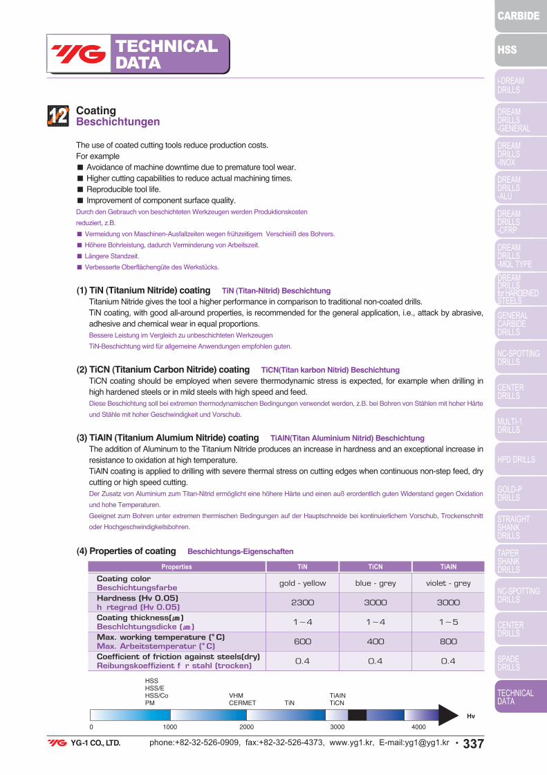
12CoatingBeschichtungen
The use of coated cutting tools reduce production costs.
For example
ö Avoidance of machine downtime due to premature tool wear.
ö Higher cutting capabilities to reduce actual machining times.
ö Reproducible tool life.
ö Improvement of component surface quality.
Durch den Gebrauch von beschichteten Werkzeugen werden Produktionskosten
reduziert, z.B.
ö Vermeidung von Maschinen-Ausfallzeiten wegen frühzeitigem Verschieiß des Bohrers.
ö Höhere Bohrleistung, dadurch Verminderung von Arbeitszeit.
ö Längere Standzeit.
ö Verbesserte Oberflächengüte des Werkstücks.
(1) TiN (Titanium Nitride) coating TiN (Titan-Nitrid) Beschichtung
Titanium Nitride gives the tool a higher performance in comparison to traditional non-coated drills.
TiN coating, with good all-around properties, is recommended for the general application, i.e., attack by abrasive,
adhesive and chemical wear in equal proportions.
Bessere Leistung im Vergleich zu unbeschichteten Werkzeugen
TiN-Beschichtung wird für allgemeine Anwendungen empfohlen guten.
(2) TiCN (Titanium Carbon Nitride) coating TiCN(Titan karbon Nitrid) Beschichtung
TiCN coating should be employed when severe thermodynamic stress is expected, for example when drilling in
high hardened steels or in mild steels with high speed and feed.
Diese Beschichtung soll bei extremen thermodynamischen Bedingungen verwendet werden, z.B. bei Bohren von Stählen mit hoher Härte
und Stähle mit hoher Geschwindigkeit und Vorschub.
(3) TiAlN (Titanium Alumium Nitride) coating TiAlN(Titan Aluminium Nitrid) Beschichtung
The addition of Aluminum to the Titanium Nitride produces an increase in hardness and an exceptional increase in
resistance to oxidation at high temperature.
TiAlN coating is applied to drilling with severe thermal stress on cutting edges when continuous non-step feed, dry
cutting or high speed cutting.
Der Zusatz von Aluminium zum Titan-Nitrid ermöglicht eine höhere Härte und einen auß erordentlich guten Widerstand gegen Oxidation
und hohe Temperaturen.
Geeignet zum Bohren unter extremen thermischen Bedingungen auf der Hauptschneide bei kontinuierlichem Vorschub, Trockenschnitt
oder Hochgeschwindigkeitsbohren.
(4) Properties of coating Beschichtungs-Eigenschaften
Coating colorBeschichtungsfarbe
Hardness (Hv 0.05)h! rtegrad (Hv 0.05)
Coating thickness( )Beschlchtungsdicke ( )
Max. working temperature ( C)Max. Arbeitstemperatur ( C)
Coefficient of friction against steels(dry)Reibungskoeffizient f! r stahl (trocken)
TiAINTiCNTiNProperties
gold - yellow
2300
1≠4
600
0.4
blue - grey
3000
1≠4
400
0.4
violet - grey
3000
1≠5
800
0.4
HSSHSS/EHSS/CoPM
0 1000 2000 3000 4000
VHMCERMET TiN
TiAINTiCN
Hv
!"#$%&'()&"&*$$' !&+!'+&$!',"-$./$$ &&0$$$$ !$

338U phone:+82-32-526-0909, fax:+82-32-526-4373, www.yg1.kr, E-mail:[email protected]
TECHNICAL
DATA
i-DREAM DRILLS
DREAMDRILLS-GENERAL
DREAMDRILLS-INOX
DREAMDRILLS-ALU
DREAMDRILLS-CFRP
DREAMDRILLS-MQL TYPE
DREAMDRILLSfor HARDENEDSTEELS
GENERALCARBIDEDRILLS
NC-SPOTTINGDRILLS
CENTERDRILLS
MULTI-1DRILLS
HPD DRILLS
GOLD-PDRILLS
STRAIGHTSHANKDRILLS
TAPERSHANKDRILLS
NC-SPOTTINGDRILLS
CENTERDRILLS
SPADEDRILLS
TECHNICALDATA
CARBIDE
HSS
13Drill sizes before TappingDurchmesser für Bohrwerkzeuge für Gewindekernlöcher
(1) Metric - ISO threads coarse pitch Metrisch - ISO Gewinde, grobverzahnt
(5) Selection of coating Verschiedene Beschichtungen
M1
M1.2
M1.4
M1.6
M1.8
M2
M2.2
M2.5
0.75
0.95
1.1
1.25
1.45
1.6
1.75
2.05
M3
M3.5
M4
M5
M6
M7
M8
M9
M10
2.5
2.9
3.3
4.2
5.0
6.0
6.8
7.8
8.5
M11
M12
M14
M16
M18
M20
M22
M24
M27
9.5
10.2
12.0
14.0
15.5
17.5
19.5
21.0
24.0
M30
M33
M36
M39
M42
M45
M48
M52
M56
26.5
29.5
32.0
35.0
37.5
40.5
43.0
47.0
50.5
Nominaldiameter
Drilldiameter
Nominaldiameter
Drilldiameter
Nominaldiameter
Drilldiameter
Nominaldiameter
Drilldiameter
(2) Metric ISO threads fine pitch
Metrisch - ISO Gewinde, feinverzahnt
2.5
3
3.5
4
4.5
5
5.5
6
0.35
0.35
0.35
0.5
0.5
0.5
0.5
0.75
2.15
2.65
3.15
3.5
4
4.5
5
5.2
Nominaldiameter
Tap PitchDrill
diameter
Work-material HSS TWIST DRILLS CARBIDE DRILLS
Unalloyed steelsUnlegierter Stahl
Steels < 1000 N/mm2
Stahls < 1000 N/mm2
Steels > 1000 N/mm2
Stahls > 1000 N/mm2
Stainless steelsEdelst! le
Cast ironGusseisen
Al-wrought alloysAl-Knetlegierungen
Al-cast alloysAl-Gusslegierungen
Copper (pure)Kupfer (pur)
BrassMessing
BronzeBronze
TiCN, TiAlN
TiCN, TiAlN
TiCN, TiAlN
TiCN, TiAlN
TiCN, TiAlN
TiN
TiCN
CrN
TiCN
TiCN
TiCN, TiAlN
TiCN, TiAlN
TiCN, TiAlN
TiCN, TiAlN
TiAlN
TiN
TiCN
CrN
TiCN
TiCN
7
8
8
9
9
10
10
10
0.75
0.75
1
0.75
1
0.75
1
1.25
6.2
7.2
7
8.2
8
9.2
9
8.8
Nominaldiameter
Tap PitchDrill
diameter
!"#$%&'()&"&*$$' !&+!'+&$!',"-$./$$ &&0$$$$ !$

339Uphone:+82-32-526-0909, fax:+82-32-526-4373, www.yg1.kr, E-mail:[email protected]
TECHNICAL
DATAi-DREAM DRILLS
DREAMDRILLS-GENERAL
DREAMDRILLS-INOX
DREAMDRILLS-ALU
DREAMDRILLS-CFRP
DREAMDRILLS-MQL TYPE
DREAMDRILLSfor HARDENEDSTEELS
GENERALCARBIDEDRILLS
NC-SPOTTINGDRILLS
CENTERDRILLS
MULTI-1DRILLS
HPD DRILLS
GOLD-PDRILLS
STRAIGHTSHANKDRILLS
TAPERSHANKDRILLS
NC-SPOTTINGDRILLS
CENTERDRILLS
SPADEDRILLS
TECHNICALDATA
CARBIDE
HSS
(3) WITHWORTH pipe threads (BSP)
WITHWORTH Rohrgewinde (BSP)
G1/8
G1/4
G3/8
G1/2
G5/8
G3/4
G7/8
G1
G11/8
8.8
11.8
15.25
19.0
21.0
24.5
28.25
30.75
35.5
G1N1/4
G1N3/8
G1N1/2
G1N3/4
G2
G2N1/4
G2N1/2
G2N3/4
G3
39.5
42.0
45.0
51.0
57.0
63.0
73.0
79.0
85.0
Nominalsize
inches
Drilldiameter
mm
Nominalsize
inches
Drilldiameter
mm
11
11
12
12
12
14
14
14
15
15
16
16
17
17
18
18
18
20
20
20
22
22
22
24
24
24
25
25
25
26
27
27
27
28
28
28
0.75
1
1
1.25
1.5
1
1.25
1.5
1
1.5
1
1.5
1
1.5
1
1.5
2
1
1.5
2
1
1.5
2
1
1.5
2
1
1.5
2
1.5
1
1.5
2
1
1.5
2
10.2
10
11
10.8
10.5
13
12.8
12.5
14
13.5
15
14.5
16
15.5
17
16.5
16
19
18.5
18
21
20.5
20
23
22.5
22
24
23.5
23
24.5
26
25.5
25
27
26.5
26
Nominaldiameter
Tap PitchDrill
diameter
30
30
30
30
32
32
33
33
33
35
36
36
36
38
39
39
39
40
40
40
42
42
42
45
45
45
48
48
48
50
50
50
52
52
52
1
1.5
2
3
1.5
2
1.5
2
3
1.5
1.5
2
3
1.5
1.5
2
3
1.5
2
3
1.5
2
3
1.5
2
3
1.5
2
3
1.5
2
3
1.5
2
3
29
28.5
28
27
30.5
30
31.5
31
30
33.5
34.5
34
33
36.5
37.5
37
36
38.5
38
37
40.5
40
39
43.5
43
42
46.5
46
45
48.5
48
47
50.5
50
49
Nominaldiameter
Tap PitchDrill
diameter
!"#$%&'()&"&*$$' !&+!'+&$!',"-$./$$ &&($$$$ !$

340U phone:+82-32-526-0909, fax:+82-32-526-4373, www.yg1.kr, E-mail:[email protected]
TECHNICAL
DATA
i-DREAM DRILLS
DREAMDRILLS-GENERAL
DREAMDRILLS-INOX
DREAMDRILLS-ALU
DREAMDRILLS-CFRP
DREAMDRILLS-MQL TYPE
DREAMDRILLSfor HARDENEDSTEELS
GENERALCARBIDEDRILLS
NC-SPOTTINGDRILLS
CENTERDRILLS
MULTI-1DRILLS
HPD DRILLS
GOLD-PDRILLS
STRAIGHTSHANKDRILLS
TAPERSHANKDRILLS
NC-SPOTTINGDRILLS
CENTERDRILLS
SPADEDRILLS
TECHNICALDATA
CARBIDE
HSS
No. 1
No. 2
No. 3
No. 4
No. 5
No. 6
No. 8
No. 10
No. 12
1/4
5/16
3/8
53
50
47
43
38
36
29
25
16
7
F
5/16
1.51
1.78
1.99
2.26
2.58
2.71
3.45
3.8
4.5
5.11
6.53
7.94
9.35
10.71
12.30
13.49
16.67
19.44
22.22
25.00
28.18
30.95
34.13
7/16
1/2
9/16
5/8
3/4
7/8
1
1N1/8
1N1/4
1N3/8
1N1/2
U
27/64
31/64
17/32
21/32
49/64
7/8
63/64
1N7/64
1N7/32
1N11/32
UNCDrill diameter
inches mmUNC
Drill diameter
inches mm
(4) American unified coarse threads Amerikanischer Standard, Grobverzahnung
No. 0
No. 1
No. 2
No. 3
No. 4
No. 5
No. 6
No. 8
No. 10
No. 12
1/4
5/16
3/64
53
50
45
42
37
33
29
21
14
3
1
1.19
1.51
1.78
2.08
2.37
2.64
2.87
3.45
4.04
4.62
5.41
6.91
8.43
9.92
11.51
13.10
14.86
17.46
20.64
23.42
26.59
29.76
32.94
36.11
3/8
7/16
1/2
9/16
5/8
3/4
7/8
1
1N1/8
1N1/4
1N3/8
1N1/2
Q
25/64
29/64
33/64
37/64
11/16
13/16
59/64
1N3/64
1N11/32
1N19/32
1N27/64
NFDrill diameter
inches mmNF
Drill diameter
inches mm
(5) American unified fine threads Amerikanischer Standard, Feinverzahnung
14ISO Tolerance ISO Toleranz
Diameter(mm)
1 - 3from to
3 - 6over to
6 - 10over to
10 - 18over to
18 - 30over to
30 - 50over to
0
- 9
0
- 15
0
- 22
+ 21
+ 6
0
- 8
0
- 12
0
- 18
+ 16
+ 4
0
- 6
0
- 10
0
- 14
+ 12
+ 2
0
- 13
0
- 21
0
- 33
+ 29
+ 8
0
- 16
0
- 25
0
- 39
+ 34
+ 9
Tolerance range in ≠ / Toleranzwerte in ≠
0
- 11
0
- 18
0
- 27
+ 25
+ 7
h6
h7
h8
m7
≠=1/1000mm
!"#$%&'()&"&*$$' !&+!'+&$!',"-$./$$ &" $$$$ !$
341Uphone:+82-32-526-0909, fax:+82-32-526-4373, www.yg1.kr, E-mail:[email protected]
TECHNICAL
DATAi-DREAM DRILLS
DREAMDRILLS-GENERAL
DREAMDRILLS-INOX
DREAMDRILLS-ALU
DREAMDRILLS-CFRP
DREAMDRILLS-MQL TYPE
DREAMDRILLSfor HARDENEDSTEELS
GENERALCARBIDEDRILLS
NC-SPOTTINGDRILLS
CENTERDRILLS
MULTI-1DRILLS
HPD DRILLS
GOLD-PDRILLS
STRAIGHTSHANKDRILLS
TAPERSHANKDRILLS
NC-SPOTTINGDRILLS
CENTERDRILLS
SPADEDRILLS
TECHNICALDATA
CARBIDE
HSS
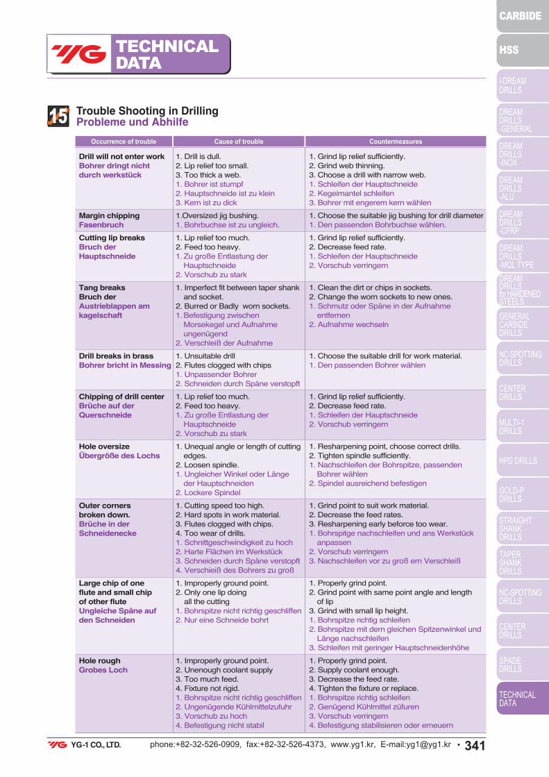
15Trouble Shooting in Drilling Probleme und Abhilfe
Occurrence of trouble Cause of trouble
Drill will not enter workBohrer dringt nichtdurch werkstück
Margin chippingFasenbruch
Cutting lip breaksBruch derHauptschneide
Tang breaksBruch derAustrieblappen amkagelschaft
Drill breaks in brassBohrer bricht in Messing
Chipping of drill centerBrüche auf derQuerschneide
Hole oversizeÜbergröße des Lochs
Outer cornersbroken down.Brüche in derSchneidenecke
Large chip of oneflute and small chipof other fluteUngleiche Späne aufden Schneiden
Hole roughGrobes Loch
1. Drill is dull.
2. Lip relief too small.
3. Too thick a web.
1. Bohrer ist stumpf
2. Hauptschneide ist zu klein
3. Kern ist zu dick
1.Oversized jig bushing.
1. Bohrbuchse ist zu ungleich.
1. Lip relief too much.
2. Feed too heavy.
1.Zu große Entlastung der
Hauptschneide
2. Vorschub zu stark
1. Imperfect fit between taper shank
and socket.
2. Burred or Badly worn sockets.
1.Befestigung zwischen
Morsekegel und Aufnahme
ungenügend
2. Verschleiß der Aufnahme
1. Unsuitable drill
2. Flutes clogged with chips
1. Unpassender Bohrer
2. Schneiden durch Späne verstopft
1. Lip relief too much.
2. Feed too heavy.
1. Zu große Entlastung der
Hauptschneide
2. Vorschub zu stark
1. Unequal angle or length of cutting
edges.
2. Loosen spindle.
1. Ungleicher Winkel oder Länge
der Hauptschneiden
2. Lockere Spindel
1. Cutting speed too high.
2. Hard spots in work material.
3. Flutes clogged with chips.
4. Too wear of drills.
1. Schnittgeschwindigkeit zu hoch
2. Harte Flächen im Werkstück
3. Schneiden durch Späne verstopft
4. Verschieiß des Bohrers zu groß
1. Improperly ground point.
2. Only one lip doing
all the cutting
1. Bohrspitze nicht richtig geschliffen
2. Nur eine Schneide bohrt
1. Improperly ground point.
2. Unenough coolant supply
3. Too much feed.
4. Fixture not rigid.
1. Bohrspitze nicht richtig geschliffen
2. Ungenügende Kühlmittelzufuhr
3. Vorschub zu hoch
4. Befestigung nicht stabil
1. Grind lip relief sufficiently.
2. Grind web thinning.
3. Choose a drill with narrow web.
1. Schleifen der Hauptschneide
2. Kegeimantel schleifen
3. Bohrer mit engerem kern wählen
1. Choose the suitable jig bushing for drill diameter
1. Den passenden Bohrbuchse wählen.
1. Grind lip relief sufficiently.
2. Decrease feed rate.
1. Schleifen der Hauptschneide
2. Vorschub verringern
1. Clean the dirt or chips in sockets.
2. Change the worn sockets to new ones.
1. Schmutz oder Späne in der Aufnahme
entfernen
2. Aufnahme wechseln
1. Choose the suitable drill for work material.
1. Den passenden Bohrer wählen
1. Grind lip relief sufficiently.
2. Decrease feed rate.
1. Schleifen der Hauptschneide
2. Vorschub verringern
1. Resharpening point, choose correct drills.
2. Tighten spindle sufficiently.
1. Nachschleifen der Bohrspitze, passenden
Bohrer wählen
2. Spindel ausreichend befestigen
1. Grind point to suit work material.
2. Decrease the feed rates.
3. Resharpening early beforce too wear.
1. Bohrspitge nachschleifen und ans Werkstück
anpassen
2. Vorschub verringern
3. Nachschleifen vor zu groß ern Verschleiß
1. Properly grind point.
2. Grind point with same point angle and length
of lip
3. Grind with small lip height.
1. Bohrspitze richtig schleifen
2. Bohrspitze mit dern gleichen Spitzenwinkel und
Länge nachschleifen
3. Schleifen mit geringer Hauptschneidenhöhe
1. Properly grind point.
2. Supply coolant enough.
3. Decrease the feed rate.
4. Tighten the fixture or replace.
1. Bohrspitze richtig schleifen
2. Genügend Kühlmittel züfuren
3. Vorschub verringern
4. Befestigung stabilisieren oder erneuern
Countermeasures
!"#$%&'()&"&*$$' !&+!'+&$!',"-$./$$ &"!$$$$ !$
342U phone:+82-32-526-0909, fax:+82-32-526-4373, www.yg1.kr, E-mail:[email protected]
TECHNICAL
DATA
i-DREAM DRILLS
DREAMDRILLS-GENERAL
DREAMDRILLS-INOX
DREAMDRILLS-ALU
DREAMDRILLS-CFRP
DREAMDRILLS-MQL TYPE
DREAMDRILLSfor HARDENEDSTEELS
GENERALCARBIDEDRILLS
NC-SPOTTINGDRILLS
CENTERDRILLS
MULTI-1DRILLS
HPD DRILLS
GOLD-PDRILLS
STRAIGHTSHANKDRILLS
TAPERSHANKDRILLS
NC-SPOTTINGDRILLS
CENTERDRILLS
SPADEDRILLS
TECHNICALDATA
CARBIDE
HSS
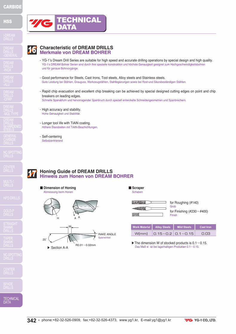
16Characteristic of DREAM DRILLS Merkmale von DREAM BOHRER
17Honing Guide of DREAM DRILLSHinweis zum Honen von DREAM BOHRER
- YG-1’s Dream Drill Series are suitable for high speed and accurate drilling operations by special design and high quality.YG-1’s DREAM Bohrer Serien sind durch ihre spezielle konstruktion und höchste Genauigkeit geeignet zum Hochgeschwindigkeitsbohren
und für genaue Bohrvorgänge.
- Good performance for Steels, Cast Irons, Tool steels, Alloy steels and Stainless steels.Gute Leistung bei Stählen, Grauguss, Werkzeugstählen, Stahllegierungen sowie bei Rost-und Säurebeständigen Stählen.
- Rapid chip evacuation and excellent chip breaking can be achieved by special designed cutting edges on point and chip
breakers on leading edges.Schnelle Spanabfuhr und hervorragender Spanbruch durch speziell entwickelte Schneidengeometrien und Spanbrechern.
- High accuracy and stability.Hohe Genauigkeit und Stabilität.
- Longer tool life with TiAlN coating.Höhere Standzeiten mit TiAlN-Beschichtungen.
- Self-centeringSelbstzentrierend
∫ Section A-A
∫The dimension W of stocked products is 0.1≠0.15.Das Maß w ist bei lagerhaltigen Produkten 0.1≠0.15.
·Dimension of Honing Abmessung beim Honen
·Scraper Schaben
for Roughing (#140) Grob
for Finishing (#230≠#400)Finish
Work Material Alloy Steels Mild Steels Cast Iron
W(mm) 0.15≠0.2 0.1≠0.15 0.03
W
25£
RAKE ANGLESpanwinkel
R0.01≠0.02mm
AH A
!"#$%&'()&"&*$$' !&+!'+&$!',"-$./$$ &"'$$$$ !$

343Uphone:+82-32-526-0909, fax:+82-32-526-4373, www.yg1.kr, E-mail:[email protected]
TECHNICAL
DATAi-DREAM DRILLS
DREAMDRILLS-GENERAL
DREAMDRILLS-INOX
DREAMDRILLS-ALU
DREAMDRILLS-CFRP
DREAMDRILLS-MQL TYPE
DREAMDRILLSfor HARDENEDSTEELS
GENERALCARBIDEDRILLS
NC-SPOTTINGDRILLS
CENTERDRILLS
MULTI-1DRILLS
HPD DRILLS
GOLD-PDRILLS
STRAIGHTSHANKDRILLS
TAPERSHANKDRILLS
NC-SPOTTINGDRILLS
CENTERDRILLS
SPADEDRILLS
TECHNICALDATA
CARBIDE
HSS
18Use of DREAM DRILLS Verwendung von DREAM BOHRER
19Shank Type DREAM DRILLS with Coolant HolesSchaftausführung DREAM BOHRER mit Kühlkanal
∫Chucking with spring collet correctly.Richtiges Spannen mit Spannzangen.
∫Radial run out at cutting lip must not exceed 0.025 mm.Radialer Rundlauf und der Schneidlippe darf nicht 0.025
überschreiten.
∫Tighten clamp of work piece.Sicheres Spannen des Werkstückes
∫Supply coolant enough to the entrance of hole.Ausreichend Kühlmittelzufluss am Bohrloch.
∫When using Dream Drills with Coolant holes, supply high
pressure coolant.Beim Verwenden von DREAM BOHRER mit Kühlkanal wird
Hochdruckkühlung benötigt.
BadSchlecht
BadSchlecht
BadSchlecht
GoodGut
GoodGut
GoodGut
GoodGut
Within 0.025Innerhalb 0.025
Form HA Form HB Form HE
Form HAK Form HBK Form HEK
∫ Shank Type of stocked products is Form HA.Schaftausführung von lagerhaltigen Produkten ist HA.
∫ Other shank types are available on your request.Andere Schaftausführungen können geliefert werden.
!"#$%&'()&"&*$$' !&+!'+&$!',"-$./$$ &"&$$$$ !$