Technical data Connection and display components ...
70
Automation system CPX-E
Transcript of Technical data Connection and display components ...

Automation system CPX-E
TOC BookmarkAutomation system CPX-EKey features
Peripherals overview
Key features – Mounting
Key features – Power supply
Key features – Diagnostics
Key features – Addressing
Data sheet – Stand-alone controller
Technical data
Connection and display components
Dimensions
Ordering data
Data sheet – PROFINET controller
Technical data
Connection and display components
Dimensions
Ordering data
Data sheet – EtherNet/IP controller
Technical data
Connection and display components
Dimensions
Ordering data
Data sheet – PROFINET bus module
Technical data
Connection and display components
Dimensions
Ordering data
Data sheet – EtherCAT bus module
Technical data
Connection and display components
Dimensions
Ordering data
Data sheet – EtherNet/IP bus mod-ule
Technical data
Connection and display components
Dimensions
Ordering data
Data sheet – PROFIBUS bus module
Technical data
Connection and display components
Dimensions
Ordering data
Data sheet – Digital input modules
Technical data
Connection and display components
Dimensions
Ordering data
Data sheet – Digital counter mod-ules
Technical data
Connection and display components
Dimensions
Ordering data
Data sheet – Digital output modules
Technical data
Connection and display components
Dimensions
Ordering data
Data sheet – Analogue input mod-ules
Technical data
Connection and display components
Dimensions
Ordering data
Data sheet – Analogue output mod-ules
Technical data
Connection and display components
Dimensions
Ordering data
Data sheet – IO-Link master mod-ules
Technical data
Connection and display components
Dimensions
Ordering data
Ordering table

2 d Internet: www.festo.com/catalogue/... Subject to change – 2021/12
Automation system CPX-E
Key features
Key features
The automation system CPX-E is a high-performance control and automa-tion system focusing primarily on motion control functions for handling technology. It comprises individual function modules that allow a very flexible system structure.Depending on the combination, the automation system CPE-X can be con-figured and used purely as a remote I/O system or as a control system. The following modules are available:• Controller• Bus modules• Input/output modules• Counter modules• IO-Link master modules
The controllers for the automation sys-tem CPX-E are powerful and have com-prehensive PLC functions. They have an integrated EtherCAT master for commu-nication with other products such as motor controllers.There is support for SoftMotion, de-pending on the variant. SoftMotion is a powerful software library for simple and complex motion control applications.All controllers have an integrated bus interface; an additional bus module for connection to higher-order controllers is not required.
• Standardised CODESYS program-ming interface
• Reduced development work through seamless data management
• Extended software functions for seamless integration and simplified control of electric drives
• Standardised, integrated platform combining servo technology and stepper motor technology, enabling mixed operation of the two technol-ogies without problems in the application
Scalable motion control functions:• Simple movements• Multi-axis movements (cam discs)• Contour applications• Robotics
Handling technology using Festo kine-matics (planar surface gantry, linear gantry, Cartesian three-dimensional gantries)• Parts handling• Assembly systems• Palletising• Gluing, dispensing
Complete automation of machines:• Packaging machinery• Palletising systems• Assembly machines• Handling systems
Key features

32021/12 – Subject to change d Internet: www.festo.com/catalogue/...
Automation system CPX-E
Key features
Overview
1
6
2
4
5
3
1
[1] Higher-order controller[2] Valve terminal with I-Port inter-
face/device with IO-Link interface
[3] Cylinder with sensors for position sensing
[4] Flow sensor[5] Visual indicator
[6] Automation system CPX-E
Ordering data – Product optionsConfigurable productThis product and all its product options can be ordered using the configurator.
The configurator can be found atd www.festo.com/catalogue/…Enter the part number or the type.
Part no. 5237644
TypeCPX-E

4 d Internet: www.festo.com/catalogue/... Subject to change – 2021/12
Automation system CPX-E
Product range overview
Function Design Type a Page
Controllers and bus modules
ControllerCODESYS V3 CPX-E-CEC-C1 • EtherCAT master
• Stand-alone controller• Ethernet interface (EasyIP, Modbus TCP,
TCP/IP, OPC-UA)• CODESYS
12
CPX-E-CEC-C1-PN • EtherCAT master• Communication via PROFINET IRT (Slave),
EasyIP, Modbus TCP or TCP/IP• Ethernet interface (EasyIP, Modbus TCP,
TCP/IP, OPC-UA)• CODESYS
17
CPX-E-CEC-C1-EP • EtherCAT master• Communication via EtherNet/IP (Slave),
EasyIP, Modbus TCP or TCP/IP• Ethernet interface (EasyIP, Modbus TCP,
TCP/IP, OPC-UA)• CODESYS
25
CODESYS V3 with SoftMotion CPX-E-CEC-M1 • EtherCAT master• Stand-alone controller• Ethernet interface (EasyIP, Modbus TCP,
TCP/IP, OPC-UA)• CODESYS• SoftMotion functionality
12
CPX-E-CEC-M1-PN • EtherCAT master• Communication via PROFINET IRT (Slave),
EasyIP, Modbus TCP or TCP/IP• Ethernet interface (EasyIP, Modbus TCP,
TCP/IP, OPC-UA)• CODESYS• SoftMotion functionality
17
CPX-E-CEC-M1-EP • EtherCAT master• Communication via EtherNet/IP (Slave),
EasyIP, Modbus TCP or TCP/IP• Ethernet interface (EasyIP, Modbus TCP,
TCP/IP, OPC-UA)• CODESYS• SoftMotion functionality
25
Bus modulePROFINET CPX-E-PN • Actuation via PROFINET
• Ethernet interface32
EtherCAT CPX-E-EC • Actuation via EtherCAT• Ethernet interface
36
EtherNet/IP CPX-E-EP • Actuation via EtherNet/IP• Ethernet interface
40
PROFIBUS CPX-E-PB • Activation via PROFIBUS• Sub-D interface
44
Product range overview

52021/12 – Subject to change d Internet: www.festo.com/catalogue/...
Automation system CPX-E
Product range overview
Function Design Type a Page
Input module Digital16 inputs CPX-E-16DI • LED display
• PNP (positive switching)• 2- and 3-wire sensors to IEC 61131-2
48
1 counter input CPX-E-1CI • LED display• Incremental encoder with two phase-offset
signals and optional signal 0• Pulse generator with or without direction
signal• Differential encoder input with 5 V DC
operating voltage• Single encoder input (single ended) with
5 V DC or 24 V DC operating voltage
51
Analogue4 inputs CPX-E-4AI-U-I • LED display
• Measured variable: current or voltage, can be set
• Analogue input can be set up to 10 V/up to 20 mA
58
Output module Digital8 outputs CPX-E-8DO • LED display
• PNP (positive switching)• Characteristic curve outputs to IEC 61131-2,
type 0.5
55
Analogue4 outputs CPX-E-4AO-U-I • LED display
• Measured variable: current or voltage, can be set
• Analogue input can be set up to 10 V/up to 20 mA
62
Master module IO-Link4 ports CPX-E-4IOL • LED display
• Protocol version Master V 1.166

6 d Internet: www.festo.com/catalogue/... Subject to change – 2021/12
Automation system CPX-E
Peripherals overview
1
5
2
3
5
4
2
6
6
1
7
Type Description a Page/Internet
[1] Retaining bracket CAFM-X3-HC Prevents the CPX-E from slipping on the H-rail –[2] Electrical manifold module VAEA-X3-L Electrical connection between the individual modules of the CPX-E –[3] Controller/bus module CPX-E-CEC
CPX-E-PNCPX-E-ECCPX-E-EPCPX-E-PB
Connection of the CPX-E to a higher-order controller 1232364044
[4] Connecting cable NEBC For connection to the higher-order controller –[5] Input/output module
Counter moduleIO-Link master module
CPX-E-16DICPX-E-1CICPX-E-8DOCPX-E-4AI-U-ICPX-E-4AO-U-ICPX-E-4IOL
Digital and analogue input and output modules 485155586266
[6] Terminal strip NEKC Blocks with spring-loaded terminals for connecting sensors and actuators –[7] DIN mounting rail NRH-35-2000 H-rail to EN 60715 nrh
Peripherals overview

72021/12 – Subject to change d Internet: www.festo.com/catalogue/...
Automation system CPX-E
Key features – Mounting
Mounting
The automation system CPX-E can only be mounted on an H-rail.Modules can easily be removed, replaced or added at a later date.
The following mounting clearances are recommended to allow sufficient venti-lation of the automation system CPX-E:
• At the top: 4 cm• At the side: 2 cm• At the bottom: 3 cm
H- - Note
Assembly must only take place in a de-energised state.
Mounting – Electrical manifold module
The electrical manifold modules are clipped into the H-rail. They can be moved along the H-rail.The electrical manifold modules con-nect the individual modules of the au-tomation system CPX-E to one another. They are used for:• Data transmission• Power supply to the module• Power supply to connected sensors
Output modules have a separate pow-er infeed from which the consumers connected to the module are supplied.
The modules require different numbers of electrical manifold modules (includ-ed in the scope of delivery of the module):• One electrical manifold module per
input module• One electrical manifold module per
counter module• One electrical manifold module per
output module• One electrical manifold module per
IO-Link master module• Two electrical manifold modules per
bus module• Two electrical manifold modules per
stand-alone controller• Four electrical manifold modules
per PROFINET controller• Four electrical manifold modules
per EtherNet/IP controller
Assembly – Modules
The module is attached to the H-rail or the electrical manifold module and latched in place.For removal, a screwdriver is required to undo the fastening clamp.The automation system CPX-E is pre-vented from slipping off the H-rail by laterally attaching retainers (included in the scope of delivery).
If a module is to be replaced, the asso-ciated electrical manifold module re-mains on the H-rail.If a module is missing, this interrupts the connection of the bus module/con-troller to the downstream input/output modules or IO-Link master modules.
Key features – Mounting

8 d Internet: www.festo.com/catalogue/... Subject to change – 2021/12
Automation system CPX-E
Key features – Mounting
Electrical connections
All the electrical connections of the automation system CPX-E are designed as terminal strips with spring-loaded terminals.
Modules can easily be removed, replaced or added at a later date. H- - Note
Assembly must only take place in a de-energised state.
Mounting – Single wire
The electrical connection for the inputs and outputs, as well as the power sup-ply, is provided via terminal strips for single strands.
Mounting – Terminal strip
The terminal strips mounted on a mod-ule are held in position by a central locking mechanism.To remove individual terminal strips, the locking mechanism is released us-ing a screwdriver:• Simple changeover of connected
sensors or actuators• Fast and visible disconnection and
reconnection of the power supply
• Simple changeover of an entire CPX-E module, wiring is retained
The terminal strips have a partially coded plug pattern:• Terminal strips with the same num-
ber of pins can be interchanged• Terminal strips for power supply
connections only fit on power supply connections
Labelling
A hinged identification holder is avail-able for the input and output modules and IO-Link master modules.
A matching label strip is inserted into the identification holder for labelling.
92021/12 – Subject to change d Internet: www.festo.com/catalogue/...
Automation system CPX-E
Key features – Power supply
Power supply concept
1
2 3 3
4
[1] The power supply is provided via a terminal strip with spring-load-ed terminals on the module
[2] The power supply for the modules themselves and the connected sensors is provided centrally on the bus module/controller.
[3] The power supply for connected actuators is provided via a termi-nal strip with spring-loaded ter-minals on the respective output module/IO-Link master module
[4] The power supply for actuators can be looped through from output module to output module/IO-Link master module
Electrical manifold modules represent the backbone of the automation sys-tem CPX-E with all supply cables. They provide the power supply for the mod-ules used on them as well as their bus connections.For segmentation into voltage zones, the power supply for the outputs is fed in separately at the output module.This creates electrically isolated, all-pin disconnectable potential groups/voltage segments.
Key features – Power supply

10 d Internet: www.festo.com/catalogue/... Subject to change – 2021/12
Automation system CPX-E
Key features – Diagnostics
System performanceDiagnostics
Detailed diagnostic functions are needed in order to quickly locate the causes of errors in the electrical instal-lation and therefore reduce downtimes in production plants.A basic distinction is made between on-the-spot diagnostics using LEDs or an operator unit and diagnostics using a bus interface.
The automation system CPX-E supports on-the-spot diagnostics via a row of LEDs. This is separate from the connec-tion area and therefore provides good visual access to status and diagnostic information.The parameters for maximum storage time and recording method for diag-nostic messages can be set.
Module and channel-specific diagnos-tics are supported, for example:• Undervoltage detection• Short circuit detection• Open load detection• Storage of the 40 most recently
occurring errors
Diagnostic messages can be read out via the bus interface in the higher-or-der controller and visualised for the central recording and evaluation of er-ror causes. This is done using the indi-vidual fieldbus-specific channels.There is also the option of access via the integrated web server (remote maintenance via PC/web applications).
Displays
Each module has a row of LEDs for in-dicating the operating status of the module and of the connected sensors or actuators.
4
1 2
4
33
[1] LED indicators on the bus module/controller
[2] LED indicators on the input/output module, IO-Link master module
[3] System-specific LED indicator (e.g. power supply)
[4] Communication-specific LED indicator (e.g. status of network connection, switching status of sensor)
Parameterisation
Changes to the application are often required during commissioning. The parameterisable characteristics of the CPX-E modules mean that functions can be very easily changed using the configuration software.
It is therefore possible, for example, to reduce the input debounce time for an input module – normally 3 ms – to 0.1 ms on a "fast" input module for faster processes.
Depending on the modules used, parameterisation is performed via the following interfaces:• Ethernet• FieldbusThe following settings are affected by the parameterisation:• Behaviour in the event of
communication errors
• Behaviour on being switched back on
• Debounce times and signal extension
• Force settings (defining the signal status)
• Operating mode of the diagnostic memory
Key features – Diagnostics
112021/12 – Subject to change d Internet: www.festo.com/catalogue/...
Automation system CPX-E
Key features – Addressing
Addressing
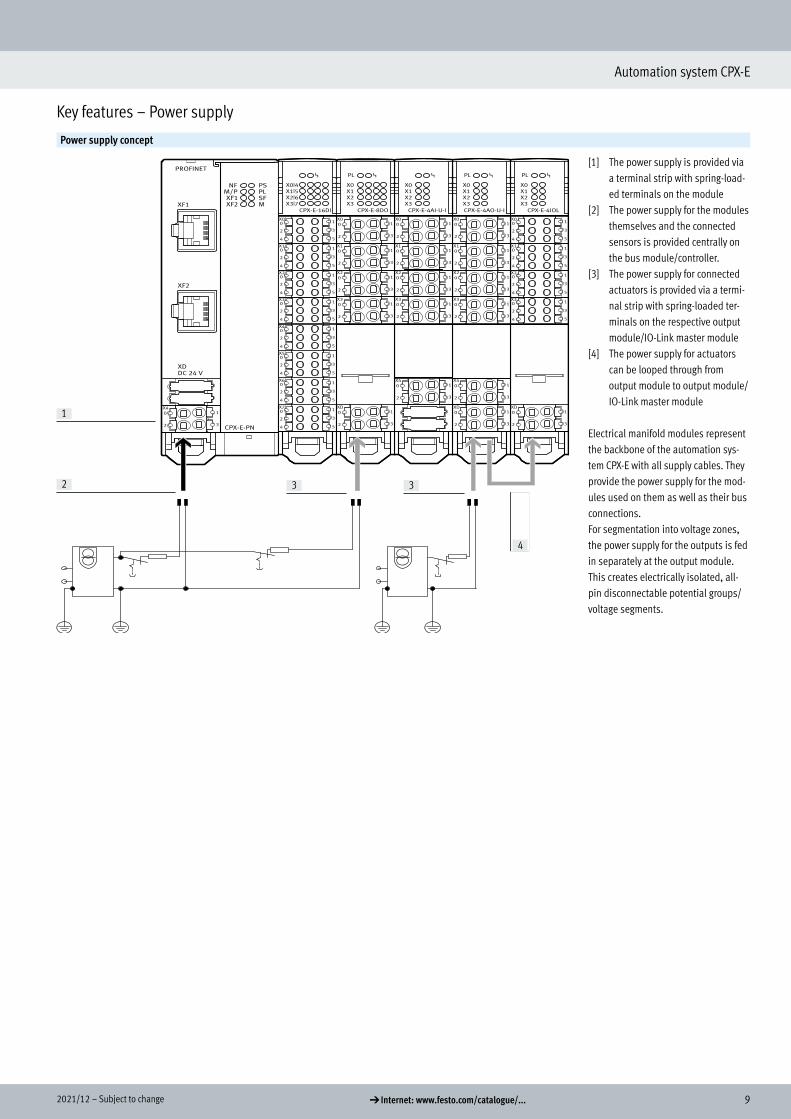
The various CPX-E modules occupy a different number of addresses within the CPX-E system. The maximum ad-dress space for bus modules depends on the performance of the fieldbus systems.
Maximum system configuration:• 1 bus module or controller• 10 input/output/counter modules
and IO-Link master modules
The maximum system configuration can be limited in individual cases by exceeding the address space.
Addresses are allocated automatically in ascending order from left to right, as viewed from the bus module/controller.
H- - Note
Please refer to the detailed descrip-tion of the configuration/addressing rules in the technical data for CPX-E bus modules.
Overview – Address space for CPX-E bus modules and controllerProtocol Max. total Max. digital Max. analogue
Inputs Outputs Inputs Outputs Inputs Outputs
CPX-E-CEC-C1 CODESYS V3 512 bits 512 bits 160 DI 80 DO 32 AI 32 AOCPX-E-CEC-M1 CODESYS V3 with SoftMotion 512 bits 512 bits 160 DI 80 DO 32 AI 32 AOCPX-E-CEC-C1-PN CODESYS V3 4096 bits 4096 bits 1280 DI 360 DO 256 AI 256 AOCPX-E-CEC-M1-PN CODESYS V3 with SoftMotion 4096 bits 4096 bits 1280 DI 360 DO 256 AI 256 AOCPX-E-CEC-C1-EP CODESYS V3 4096 bits 4096 bits 1280 DI 360 DO 256 AI 256 AOCPX-E-CEC-M1-EP CODESYS V3 with SoftMotion 4096 bits 4096 bits 1280 DI 360 DO 256 AI 256 AOCPX-E-PN PROFINET 512 bits 512 bits 160 DI 80 DO 32 AI 32 AOCPX-E-EC EtherCAT 512 bits 512 bits 160 DI 80 DO 32 AI 32 AOCPX-E-EP EtherNet/IP 512 bits 512 bits 160 DI 80 DO 32 AI 32 AOCPX-E-PB PROFIBUS 512 bits 512 bits 160 DI 80 DO 32 AI 32 AO
DI = Digital inputs (1 bit)
DO = Digital outputs (1 bit)
AO = Analogue outputs (16 bits)
AO = Analogue outputs (16 bits)
AI = Analogue inputs (16 bits)
H- - Note
The bandwidth of the bus modules can be restricted by the choice of module and the maximum number of modules.
Overview – Allocated addresses for CPX-E modulesInputs [bit] Outputs [bit]
CPX-E-16DI Digital input module, 16 inputs 16 –CPX-E-1CI Digital counter module, 1 counter input 96 16CPX-E-8DO Digital output module, 8 outputs – 8CPX-E-4AI-U-I Analogue input module, 4 inputs 64 –CPX-E-4AO-U-I Analogue output module, 4 outputs – 64CPX-E-4IOL IO-Link master module, 4 ports 64 ... 256 64 ... 256
Example of CPX-E-PN (PROFINET)Inputs [bit] Outputs [bit] Remarks
3x CPX-E-16DI 48 – • The maximum number of modules is achieved with 10 CPX-E input/output modules
• The available address space (512 bits) is not fully used up• No additional modules can be configured
1x CPX-E-8DO – 86x CPX-E-4AI-U-I 384 –Allocated address space 432 8
Key features – Addressing
12 d Internet: www.festo.com/catalogue/... Subject to change – 2021/12
Automation system CPX-E
Data sheet – Stand-alone controller
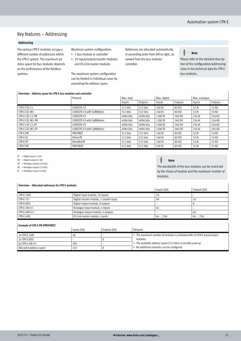
Controller for operating the automation system CPX-E as an autonomous unitProgramming and process visualis-ation take place via CODESYS.The controller includes the power sup-ply for the modules of the automation system and the connected sensors.
ApplicationEthernet connection
The controller can be accessed directly via two Ethernet interfaces.
There is also the option of connecting via Modbus/TCP or standard Ethernet (TCP/IP).
The interfaces support crossover de-tection, which means that there is a
choice of using patch cables or crossover cables.
Motion controller
.
The controller has an integrated EtherCAT master. EtherCAT is used for communication with other products:• Motor controllers (CMMP, CMMT)
• Electrical terminal (CPX)• Valve terminals with I-Port interface
via the installation system CTEL (bus node CTEU-EC)
The SoftMotion extension makes it possible to control/execute coordinat-ed multi-axis movements.
Additional functions
• Web server for read access to the most important parameter and diagnostic functions
• FTP server for data exchange • Real-time clock, can be set and read using CODESYS
• Internal temperature sensor
Data sheet – Stand-alone controller

132021/12 – Subject to change d Internet: www.festo.com/catalogue/...
Automation system CPX-E
Data sheet – Stand-alone controller
General technical data
CPU data Dual core 650 MHz128 MB RAM
Programming software CODESYS provided by FestoProgram memory 12 MB, user programBuffering time real-time clock 3 weeksProcessing time Approx. 200 µs/1 k instructionFlags 120 kB remanent data
CODESYS variable conceptFunction blocks Read CPX module diagnostics
CPX diagnostic statusCopy CPX diagnostic traceAnd others
IP address setting DHCPVia CODESYS
Control elements DIL switch for RUN/STOPConfiguration support CODESYS V3Maximum number of modules 10System parameters Diagnostic memory
Fail-safe responseSystem start
Module parameters Channel alarms bundlingUndervoltage diagnosticsChannel alarms for undervoltageProcess value representation, analogue modules
Diagnostics via LED Force modeNetwork status engineering port 1Network status EtherCATRunPower supply, electronics/sensorsPower supply loadSystem error
Address capacity of internal bus inputs/outputsMax. address capacity of outputs [byte] 64Max. address capacity of inputs [byte] 64
Technical data – Interfaces
Fieldbus interfaceProtocol EtherCAT masterFunction Bus connection outgoingTransmission rate [Mbps] 100Type EthernetConnection type SocketConnection technology RJ45Number of pins/wires 8Galvanic isolation Yes
Ethernet interfaceProtocol EasyIP
Modbus TCPTCP/IPOPC UA
Function DiagnosticsTransmission rate [Mbps] 10
[Mbps] 100Connection type SocketConnection technology RJ45Number of pins/wires 8
Technical data

14 d Internet: www.festo.com/catalogue/... Subject to change – 2021/12
Automation system CPX-E
Data sheet – Stand-alone controller
Technical data – Electrics
Nominal operating voltage DC for electronics/sensors [V DC] 24Permissible voltage fluctuations for electronics/sensors [%] ±25Power failure buffering [ms] 20Max. power supply [A] 8Intrinsic current consumption at nominal operating voltage for electronics/sensors [mA] Typically 65Protection against direct and indirect contact PELV
Electrical connection, power supplyFunction Electronics and sensorsConnection type Terminal stripConnection technology Spring-loaded terminalNumber of pins/wires 4Conductor cross section [mm2] 0.2 ... 1.5Note on conductor cross section 0.2 ... 2.5 mm2 for flexible conductor without wire end sleeve
Technical data – Mechanical components
Type of mounting With H-railProduct weight [g] 145Grid dimension [mm] 18.9Dimensions W x L x H [mm] 42.2 x 125.8 x 76.5
Materials
Housing PANote on materials RoHS-compliant
Contains paint-wetting impairment substances
Operating and environmental conditions
Ambient temperature [°C] –5 ... +50Note on ambient temperature [°C] –5 ... +60 for vertical installationStorage temperature [°C] –20 ... +70Corrosion resistance class CRC1) 0Relative humidity [%] 95
Non-condensingCE marking (see declaration of conformity)3) To EU EMC Directive2)
KC mark KC EMCCertification RCM
c UL us-Listed (OL)Certificate issuing authority UL E239998Degree of protection IP20
1) Corrosion resistance class CRC 0 to Festo standard FN 940070
No corrosion stress. Applies to small, visually unimportant standards-based parts such as threaded pins, circlips and clamping sleeves which are usually only available on the market in a phosphated or burnished version (and
possibly oiled) as well as to ball bearings (for components < CRC 3) and plain bearings.2) For information about the area of use, see the EC declaration of conformity at: www.festo.com/catalogue/CPX-E d Support/Downloads.
If the devices are subject to usage restrictions in residential, commercial or light-industrial environments, further measures for the reduction of the emitted interference may be necessary.3) Additional information: www.festo.com/catalogue/CPX-E d Support/Downloads.
Safety characteristics
CE marking (see declaration of conformity) To EU EMC DirectiveShock resistance Shock test with severity level 1 to FN 942017-5 and EN 60068-2-27Vibration resistance Transport application test with severity level 1 to FN 942017-4 and EN 60068-2-6

152021/12 – Subject to change d Internet: www.festo.com/catalogue/...
Automation system CPX-E
Data sheet – Stand-alone controller
Connection and display components
1
3
2
4
[1] Ethernet network connection[2] EtherCAT master network
connection[3] Terminal strip for operating
voltage supply[4] LED indicators
Dimensions Download CAD data a www.festo.com
B1 B2 B3 H1 H2 H3 H4 H5 H6 L1 L2 L3
CPX-E-CEC-C1 37.8 42.2 18.9 76.5 69.9 6 – 27.4 16.3 124.3 66 58.3CPX-E-CEC-M1
Connection and display components
Dimensions
16 d Internet: www.festo.com/catalogue/... Subject to change – 2021/12
Automation system CPX-E
Data sheet – Stand-alone controller
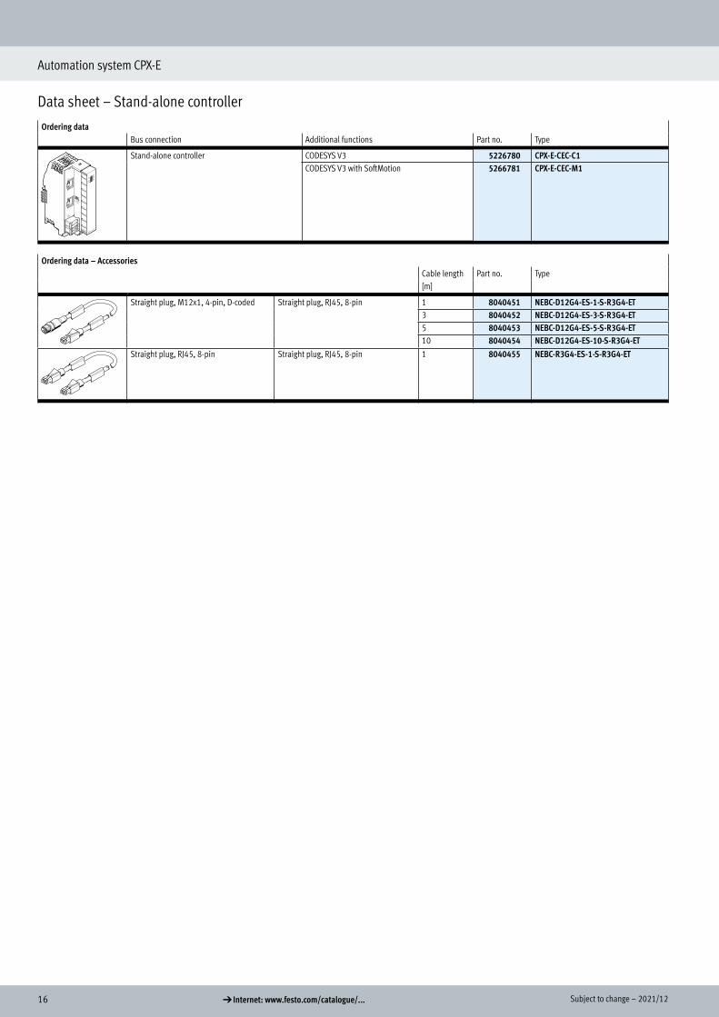
Ordering data Bus connection Additional functions Part no. Type
Stand-alone controller CODESYS V3 5226780 CPX-E-CEC-C1CODESYS V3 with SoftMotion 5266781 CPX-E-CEC-M1
Ordering data – AccessoriesCable length Part no. Type[m]
2
Straight plug, M12x1, 4-pin, D-coded Straight plug, RJ45, 8-pin 1 8040451 NEBC-D12G4-ES-1-S-R3G4-ET3 8040452 NEBC-D12G4-ES-3-S-R3G4-ET5 8040453 NEBC-D12G4-ES-5-S-R3G4-ET10 8040454 NEBC-D12G4-ES-10-S-R3G4-ET
Straight plug, RJ45, 8-pin Straight plug, RJ45, 8-pin 1 8040455 NEBC-R3G4-ES-1-S-R3G4-ET
Ordering data

172021/12 – Subject to change d Internet: www.festo.com/catalogue/...
Automation system CPX-E
Data sheet – PROFINET controller
Controller for operating the automation system CPX-E on PROFINET or as an au-tonomous unitProgramming and process visualis-ation take place via CODESYS.The controller includes the power sup-ply for the modules of the automation system and the connected sensors.
ApplicationBus connection
The bus connection is provided via RJ45 sockets which meet Ethernet requirements.Communication with a higher-order controller takes place via PROFINET. There is also the option of connecting
via Modbus/TCP or standard Ethernet (TCP/IP).The controller can be accessed directly via two Ethernet interfaces. The inte-grated switch supports star and line topology and enables the network to be divided into segments.
The controller can be operated both as a higher-order device (master) and as a subordinate device (slave) using the communication protocol Modbus/TCP.The interfaces support crossover de-tection, which means that there is a
choice of using patch cables or crossover cables.
Motion controller
The controller has an integrated EtherCAT master.EtherCAT is used for communication with other products:
• Motor controllers (CMMP, CMMT)• Electrical terminal (CPX)
• Valve terminals with I-Port interface via the installation system CTEL (bus node CTEU-EC)
The SoftMotion extension makes it possible to control/execute coordinat-ed multi-axis movements.
Data storage
An SD card slot and a USB interface are provided for reading out and storing data.
The maximum memory size for compat-ible media is 32 GB in FAT format with a partition.
There is no provision to permanently record data on the external media during operation.
Only USB storage media with a current consumption of less than 0.5 A may be used.
Additional functions
• Web server for read access to the most important parameter and diagnostic functions
• FTP server for data exchange • Real-time clock, can be set and read using CODESYS
• Internal temperature sensor
Data sheet – PROFINET controller

18 d Internet: www.festo.com/catalogue/... Subject to change – 2021/12
Automation system CPX-E
Data sheet – PROFINET controller
General technical data
CPU data Dual core 766 MHz512 MB RAM
Storage medium Micro SD card up to 32 GBUSB memory stick up to 32 GB
Programming software CODESYS provided by FestoProgram memory 100 MB, user programBuffering time real-time clock 3 weeksProcessing time Approx. 200 µs/1 k instructionFlags 120 kB remanent data
CODESYS variable conceptFunction blocks Read CPX module diagnostics
CPX diagnostic statusCopy CPX diagnostic traceAnd others
IP address setting DHCPVia CODESYSOptional: via operator unit CDSB
Control elements DIL switch for RUN/STOPOptional operator unit CDSB
Configuration support Operator unit CDSBCODESYS V3GSDML file
Maximum number of modules 10System parameters Diagnostic memory
Fail-safe responseSystem start
Module parameters Channel alarms bundlingUndervoltage diagnosticsChannel alarms for undervoltageProcess value representation, analogue modules
Diagnostics via LED Force modeNetwork errorsNetwork status engineering port 1Network status engineering port 2Network status EtherCATNetwork status port 1Network status port 2RunPower supply, electronics/sensorsPower supply loadSystem errorMaintenance required
Address capacity of internal bus inputs/outputsMax. address capacity of outputs [byte] 64Max. address capacity of inputs [byte] 64
Technical data

192021/12 – Subject to change d Internet: www.festo.com/catalogue/...
Automation system CPX-E
Data sheet – PROFINET controller
Technical data – Interfaces
Fieldbus interface 1Protocol PROFINET IOFunction Bus connection incoming/outgoingTransmission rate [Mbps] 100Type EthernetConnection type 2 x socketConnection technology RJ45Number of pins/wires 8Galvanic isolation YesMax. address capacity of outputs [byte] 512Max. address capacity of inputs [byte] 512
Fieldbus interface 2Protocol EtherCAT masterFunction Bus connection incoming/outgoingTransmission rate [Mbps] 100Type EthernetConnection type SocketConnection technology RJ45Number of pins/wires 8Galvanic isolation Yes
Ethernet interfaceProtocol EasyIP
Modbus TCPTCP/IPOPC UA
Function SwitchDiagnostics
Transmission rate [Mbps] 10[Mbps] 100
Connection type 2 x socketConnection technology RJ45Number of pins/wires 8
USB interfaceUSB interface USB 2.0

20 d Internet: www.festo.com/catalogue/... Subject to change – 2021/12
Automation system CPX-E
Data sheet – PROFINET controller
Technical data – Electrics
Nominal operating voltage DC [V DC] 24Nominal operating voltage DC for electronics/sensors [V DC] 24Permissible voltage fluctuations for electronics/sensors [%] ±25Power failure buffering [ms] 20Max. power supply [A] 8Intrinsic current consumption at nominal operating voltage for electronics/sensors [mA] Typically 150Protection against direct and indirect contact PELV
Electrical connection, power supplyFunction Electronics and sensorsConnection type Terminal stripConnection technology Spring-loaded terminalNumber of pins/wires 4Conductor cross section [mm2] 0.2 ... 1.5Note on conductor cross section 0.2 ... 2.5 mm2 for flexible conductor without wire end sleeve
Technical data – Mechanical components
Type of mounting With H-railProduct weight [g] 288Grid dimension [mm] 18.9Dimensions W x L x H [mm] 75.9 x 124.3 x 82.5
Materials
Housing PANote on materials RoHS-compliant
Contains paint-wetting impairment substances
Operating and environmental conditions
Ambient temperature [°C] –5 ... +50Note on ambient temperature [°C] –5 ... +60 for vertical installationStorage temperature [°C] –20 ... +70Corrosion resistance class CRC1) 0Relative humidity [%] 95
Non-condensingCE marking (see declaration of conformity)3) To EU EMC Directive2)
KC mark KC EMCCertification RCM
c UL us-Listed (OL)Certificate issuing authority UL E239998Degree of protection IP20
1) Corrosion resistance class CRC 0 to Festo standard FN 940070
No corrosion stress. Applies to small, visually unimportant standards-based parts such as threaded pins, circlips and clamping sleeves which are usually only available on the market in a phosphated or burnished version (and
possibly oiled) as well as to ball bearings (for components < CRC 3) and plain bearings.2) For information about the area of use, see the EC declaration of conformity at: www.festo.com/catalogue/CPX-E d Support/Downloads.
If the devices are subject to usage restrictions in residential, commercial or light-industrial environments, further measures for the reduction of the emitted interference may be necessary.3) Additional information: www.festo.com/catalogue/CPX-E d Support/Downloads.
Safety characteristics
CE marking (see declaration of conformity) To EU EMC DirectiveShock resistance Shock test with severity level 1 to FN 942017-5 and EN 60068-2-27Vibration resistance Transport application test with severity level 1 to FN 942017-4 and EN 60068-2-6

212021/12 – Subject to change d Internet: www.festo.com/catalogue/...
Automation system CPX-E
Data sheet – PROFINET controller
Connection and display components CPX-E-CEC-...
1
7
3 4
2
8
9
6
1
7
5
[1] Network connections 1 and 2, PROFINET IO
[2] Terminal strip for operating voltage supply
[3] LED indicators[4] EtherCAT master network
connection[5] USB interface[6] Slot for micro SD memory card[7] Network connections 1 and 2,
Ethernet[8] DIL switch for holding and starting
projects in CODESYS[9] Slot for operator unit CDSB
Display and operator unit CDSB-A1
3
1
2
The operator unit CDSB-A1 from Festo is a plug-in display and operating pan-el for the automation system CPX-E.The integrated colour TFT display with touchscreen can be used both for oper-ation and for simple diagnostics of the connected basic unit. User-friendliness is enhanced through fault diagnostics with plain-text error messages.
[1] CPX-E-CEC[2] Operator unit CDSB-A1[3] Cover (included in the scope of
delivery of the CPX-E-CEC)
• Display of full-text messages (errors, warnings, data)
• Easy data backup of parameters and firmware in the unit (e.g. for series commissioning or device replacement)
• 1.77" colour TFT display• 3 GB user memory
Connection and display components

22 d Internet: www.festo.com/catalogue/... Subject to change – 2021/12
Automation system CPX-E
Data sheet – PROFINET controller
SoftwareSoftware licences Licences Minimum requirement
The "Motion & Robotics" software ena-bles simple configuration and pro-gramming of the automation system CPX-E in conjunction with Festo handling systems.
Functions:• Support for Festo linear gantries
YXCL and EXCT• Support for Festo linear gantries
YXCF, EXCH and EXCM• Support for Festo 3-dimensional
gantries YXCR• Simple configuration of the
kinematics/drives in CODESYS• Web visualisation for easy operation
and commissioning
• Any required positioning thanks to free programming
• Easy-to-understand textual macro programming language
• Storage of motion programs in a project structure.
• Teach-in programming via graphic dialogue at the handheld terminal
• Motion path smoothing with full axis dynamics
• Integrated limiters for programmed dynamic values with simultaneous path accuracy
• Simple switching points along the contour for switching actions, for example gripper control
• Interface between the integrated PLC and FTL programming
2 software licenses are being offered which can be purchased from the Festo App World:
PTP licence• Point-to-point interpolation• Actuation of simple kinematic
systems• Graphic visualisation for handheld
operator unit CDSA-D3-RV• Teach-in function• For simple applications such as pick
& place, loading/unloading
CP licence• Cartesian linear and circular
interpolation• Interpolation of orientation• Contour applications• Graphic visualisation for handheld
operator unit CDSA-D3-RV• Teach-in function
• CPX-E with revision 8 or higher• For CPX-E-CEC-M1-PN• CODESYS SP 15 P3• SoftMotion version 4.6.3.0• The licences are purchased once
and then are then always available

232021/12 – Subject to change d Internet: www.festo.com/catalogue/...
Automation system CPX-E
Data sheet – PROFINET controller
Dimensions Download CAD data a www.festo.com
B1 B2 B3 H1 H2 H3 H4 H5 H6 L1 L2 L3
CPX-E-CEC-...PN 80.2 75.9 56.9 82.5 69.9 27.4 16.3 6 76.5 124.3 66 58.3
Dimensions

24 d Internet: www.festo.com/catalogue/... Subject to change – 2021/12
Automation system CPX-E
Data sheet – PROFINET controller
Ordering data Bus connection Additional functions Part no. Type
PROFINET IO CODESYS V3 4252741 CPX-E-CEC-C1-PNCODESYS V3 with SoftMotion 4252743 CPX-E-CEC-M1-PN
Ordering data – AccessoriesCable length Part no. Type[m]
2
Memory card 32 GB – 4553880 CAMC-M-MS-G32
Display and operator unit • Colour touchscreen• Diagnostic function• Update function for CPX-E-CEC (in
plugged-in state)
– 8070984 CDSB-A1
• Software licence for controlling a Festo handling system
• For CPX-E-CEC-M1-PN
Point-to-point interpolation – 8129269 GSAR-C1-L1Cartesian interpolation – 8129270 GSAR-C1-L2
Straight plug, M12x1, 4-pin, D-coded Straight plug, RJ45, 8-pin 1 8040451 NEBC-D12G4-ES-1-S-R3G4-ET3 8040452 NEBC-D12G4-ES-3-S-R3G4-ET5 8040453 NEBC-D12G4-ES-5-S-R3G4-ET10 8040454 NEBC-D12G4-ES-10-S-R3G4-ET
Straight plug, RJ45, 8-pin Straight plug, RJ45, 8-pin 1 8040455 NEBC-R3G4-ES-1-S-R3G4-ET
Ordering data

252021/12 – Subject to change d Internet: www.festo.com/catalogue/...
Automation system CPX-E
Data sheet – EtherNet/IP controller
Controller for operating the automation system CPX-E on EtherNet/IP or as an autonomous unitProgramming and process visualis-ation take place via CODESYS.The controller includes the power sup-ply for the modules of the automation system and the connected sensors.
ApplicationBus connection
The bus connection is provided via RJ45 sockets which meet Ethernet requirements.Communication with a higher-order controller takes place via EtherNet/IP. There is also the option of connecting
via Modbus/TCP or standard Ethernet (TCP/IP).The controller can be accessed directly via two Ethernet interfaces. The inte-grated switch supports star and line topology and enables the network to be divided into segments.
The controller can be operated both as a higher-order device (master) and as a subordinate device (slave) using the communication protocol Modbus/TCP.The interfaces support crossover de-tection, which means that there is a
choice of using patch cables or crossover cables
Motion controller
The controller has an integrated EtherCAT master.EtherCAT is used for communication with other products:
• Motor controllers (CMMP, CMMT)• Electrical terminal (CPX)
• Valve terminals with I-Port interface via the installation system CTEL (bus node CTEU-EC)
The SoftMotion extension makes it possible to control/execute coordinat-ed multi-axis movements.
Data storage
An SD card slot and a USB interface are provided for reading out and storing data.
The maximum memory size for compat-ible media is 32 GB in FAT format with a partition.
There is no provision to permanently record data on the external media during operation.
Only USB storage media with a current consumption of less than 0.5 A may be used.
Additional functions
• Web server for read access to the most important parameter and diagnostic functions
• FTP server for data exchange • Real-time clock, can be set and read using CODESYS
• Internal temperature sensor
Data sheet – EtherNet/IP controller

26 d Internet: www.festo.com/catalogue/... Subject to change – 2021/12
Automation system CPX-E
Data sheet – EtherNet/IP controller
General technical data
CPU data Dual core 766 MHz512 MB RAM
Storage medium Micro SD card up to 32 GBUSB memory stick up to 32 GB
Programming software CODESYS provided by FestoProgram memory 100 MB, user programBuffering time real-time clock 3 weeksProcessing time Approx. 200 µs/1 k instructionFlags 120 kB remanent data
CODESYS variable conceptFunction blocks Read CPX module diagnostics
CPX diagnostic statusCopy CPX diagnostic traceAnd others
IP address setting DHCPVia CODESYSOptional: via operator unit CDSB
Control elements DIL switch for RUN/STOPOptional operator unit CDSBRotary switch for address setting
Configuration support Operator unit CDSBCODESYS V3
Maximum number of modules 10System parameters Diagnostic memory
Fail-safe responseSystem start
Module parameters Channel alarms bundlingUndervoltage diagnosticsChannel alarms for undervoltageProcess value representation, analogue modules
Diagnostics via LED Force mode
Address capacity of internal bus inputs/outputsMax. address capacity of outputs [byte] 64Max. address capacity of inputs [byte] 64
Technical data

272021/12 – Subject to change d Internet: www.festo.com/catalogue/...
Automation system CPX-E
Data sheet – EtherNet/IP controller
Technical data – Interfaces
Fieldbus interface 1Protocol EtherNet/IPFunction Bus connection incoming/outgoingTransmission rate [Mbps] 100Type EthernetConnection type 2 x socketConnection technology RJ45Number of pins/wires 8Galvanic isolation YesMax. address capacity of outputs [byte] 512Max. address capacity of inputs [byte] 512
Fieldbus interface 2Protocol EtherCAT masterFunction Bus connection incoming/outgoingTransmission rate [Mbps] 100Type EthernetConnection type SocketConnection technology RJ45Number of pins/wires 8Galvanic isolation Yes
Ethernet interfaceProtocol EasyIP
Modbus TCPTCP/IPOPC UA
Function SwitchDiagnostics
Transmission rate [Mbps] 10[Mbps] 100
Connection type 2 x socketConnection technology RJ45Number of pins/wires 8
USB interfaceUSB interface USB 2.0

28 d Internet: www.festo.com/catalogue/... Subject to change – 2021/12
Automation system CPX-E
Data sheet – EtherNet/IP controller
Technical data – Electrics
Nominal operating voltage DC [V DC] 24Nominal operating voltage DC for electronics/sensors [V DC] 24Permissible voltage fluctuations for electronics/sensors [%] ±25Power failure buffering [ms] 20Max. power supply [A] 8Intrinsic current consumption at nominal operating voltage for electronics/sensors [mA] Typically 150Protection against direct and indirect contact PELV
Electrical connection, power supplyFunction Electronics and sensorsConnection type Terminal stripConnection technology Spring-loaded terminalNumber of pins/wires 4Conductor cross section [mm2] 0.2 ... 1.5Note on conductor cross section 0.2 ... 2.5 mm2 for flexible conductor without wire end sleeve
Technical data – Mechanical components
Type of mounting With H-railProduct weight [g] 288Grid dimension [mm] 18.9Dimensions W x L x H [mm] 75.9 x 124.3 x 82.5
Materials
Housing PANote on materials RoHS-compliant
Contains paint-wetting impairment substances
Operating and environmental conditions
Ambient temperature [°C] –5 ... +50Note on ambient temperature [°C] –5 ... +60 for vertical installationStorage temperature [°C] –20 ... +70Corrosion resistance class CRC1) 0Relative humidity [%] 95
Non-condensingCE marking (see declaration of conformity)3) To EU EMC Directive2)
KC mark KC EMCCertification RCM
c UL us-Listed (OL)Certificate issuing authority UL E239998Degree of protection IP20
1) Corrosion resistance class CRC 0 to Festo standard FN 940070
No corrosion stress. Applies to small, visually unimportant standards-based parts such as threaded pins, circlips and clamping sleeves which are usually only available on the market in a phosphated or burnished version (and
possibly oiled) as well as to ball bearings (for components < CRC 3) and plain bearings.2) For information about the area of use, see the EC declaration of conformity at: www.festo.com/catalogue/CPX-E d Support/Downloads.
If the devices are subject to usage restrictions in residential, commercial or light-industrial environments, further measures for the reduction of the emitted interference may be necessary.3) Additional information: www.festo.com/catalogue/CPX-E d Support/Downloads.
Safety characteristics
CE marking (see declaration of conformity) To EU EMC DirectiveShock resistance Shock test with severity level 1 to FN 942017-5 and EN 60068-2-27Vibration resistance Transport application test with severity level 1 to FN 942017-4 and EN 60068-2-6

292021/12 – Subject to change d Internet: www.festo.com/catalogue/...
Automation system CPX-E
Data sheet – EtherNet/IP controller
Connection and display components CPX-E-CEC-...
1
7
3 54
2
8
9
6
1
7
[1] Network connections 1 and 2, EtherNet/IP
[2] Terminal strip for operating voltage supply
[3] LED indicators[4] EtherCAT master network
connection[5] USB interface[6] Slot for micro SD memory card[7] Network connections 1 and 2,
Ethernet[8] DIL switch for holding and starting
projects in CODESYS[9] Slot for operator unit CDSB
Display and operator unit CDSB-A1
3
1
2
The operator unit CDSB-A1 from Festo is a plug-in display and operator unit for the automation system CPX-E.The integrated colour TFT display with touchscreen can be used both for oper-ation and for simple diagnostics of the connected basic unit. User-friendliness is enhanced through fault diagnostics with plain-text error messages.
[1] CPX-E-CEC[2] Operator unit CDSB-A1[3] Cover (included in the scope of
delivery of the CPX-E-CEC)
• Display of full-text messages (errors, warnings, data)
• Easy data backup of parameters and firmware in the unit (e.g. for series commissioning or device replacement)
• 1.77" colour TFT display• 3 GB user memory
Connection and display components

30 d Internet: www.festo.com/catalogue/... Subject to change – 2021/12
Automation system CPX-E
Data sheet – EtherNet/IP controller
Dimensions Download CAD data a www.festo.com
B1 B2 B3 H1 H2 H3 H4 H5 H6 L1 L2 L3
CPX-E-CEC-...EP 80.2 75.9 56.9 82.5 69.9 27.4 16.3 6 76.5 124.3 66 58.3
Dimensions

312021/12 – Subject to change d Internet: www.festo.com/catalogue/...
Automation system CPX-E
Data sheet – EtherNet/IP controller
Ordering data Bus connection Additional functions Part no. Type
EtherNet/IP CODESYS V3 4252742 CPX-E-CEC-C1-EPCODESYS V3 with SoftMotion 4252744 CPX-E-CEC-M1-EP
Ordering data – AccessoriesCable length Part no. Type[m]
2
Memory card 32 GB – 4553880 CAMC-M-MS-G32
Display and operator unit • Colour touchscreen• Diagnostic function• Update function for CPX-E-CEC (in
plugged-in state)
– 8070984 CDSB-A1
Straight plug, M12x1, 4-pin, D-coded Straight plug, RJ45, 8-pin 1 8040451 NEBC-D12G4-ES-1-S-R3G4-ET3 8040452 NEBC-D12G4-ES-3-S-R3G4-ET5 8040453 NEBC-D12G4-ES-5-S-R3G4-ET10 8040454 NEBC-D12G4-ES-10-S-R3G4-ET
Straight plug, RJ45, 8-pin Straight plug, RJ45, 8-pin 1 8040455 NEBC-R3G4-ES-1-S-R3G4-ET
Ordering data

32 d Internet: www.festo.com/catalogue/... Subject to change – 2021/12
Automation system CPX-E
Data sheet – PROFINET bus module
Bus module for operating the automa-tion system CPX-E on PROFINET. Data is transmitted on the basis of Industrial Ethernet.The bus module includes the power supply for the modules of the automa-tion system and the connected sensors.
ApplicationBus connection Additional functions Device description file Web server
The bus connection is provided via RJ45 sockets which meet Ethernet requirements.Communication with a higher-order controller takes place via PROFINET with real-time protocol (real time RT or isochronous real time IRT).The integrated switch supports star and line topology and enables the network to be divided into segments.
• The bus module supports PROFIenergy for reducing the energy requirement through selective switching off of consumers when they are not required
• The bus module has crossover de-tection, which means that there is the option of using patch cables or crossover cables
The bus module is configured using a device description file (GSDML file) which includes all the necessary infor-mation for parameterisation.
The integrated web server enables read access to the most important parameter and diagnostic functions.
General technical data
Fieldbus interfaceProtocol PROFINET IRT
PROFINET IRTFunction Bus connection incoming/outgoingTransmission rate [Mbps] 100Type EthernetConnection type 2 x socketConnection technology RJ45Number of pins/wires 8Galvanic isolation YesMax. address volume for outputs [byte] 64Max. address capacity inputs [byte] 64
Address capacity of internal bus inputs/outputsMax. address capacity of outputs [byte] 64Note on outputs 62 bytes with I/O diagnostic interface
64 bytes with status bits64 bytes without diagnostics
Max. address capacity of inputs [byte] 64Note on inputs 62 bytes with I/O diagnostic interface
62 bytes with status bits64 bytes without diagnostics
Data sheet – PROFINET bus module
Technical data

332021/12 – Subject to change d Internet: www.festo.com/catalogue/...
Automation system CPX-E
Data sheet – PROFINET bus module
General data
Configuration support GSDML fileMaximum number of modules 10Additional functions LLDP
MRPMRPDPROFINET FSUPROFINET I&MO..3, 1..3 retentive memory possiblePROFINET Shared deviceS2 system redundancySNMP
System parameters Diagnostic memoryFail-safe responseForce modeSystem start
Module parameters Channel alarms bundlingUndervoltage diagnosticsChannel alarms for undervoltageProcess value representation, analogue modules
Diagnostics via LED Force modeNetwork errorsNetwork status connection 1Network status connection 2Power supply, electronics/sensorsPower supply loadSystem errorMaintenance required
Diagnostics via the bus Parameterisation errorLower limit value not observedUpper limit value not observedWire breakShort circuitPROFIsafe addresses differentUndervoltageExcessive temperature
Technical data – Electrics
Nominal operating voltage DC for electronics/sensors [V DC] 24Permissible voltage fluctuations for electronics/sensors [%] ±25Power failure buffering [ms] 20Max. power supply [A] 8Intrinsic current consumption at nominal operating voltage for electronics/sensors [mA] Typically 75Protection against direct and indirect contact PELV
Electrical connection, power supplyFunction Electronics and sensorsConnection type Terminal stripConnection technology Spring-loaded terminalNumber of pins/wires 4Conductor cross section [mm2] 0.2 ... 1.5Note on conductor cross section [mm2] 0.2 ... 2.5 for flexible wire without wire end sleeve
Technical data – Mechanical components
Type of mounting With H-railProduct weight [g] 145Grid dimension [mm] 18.9Dimensions W x L x H [mm] 42.2 x 125.8 x 76.5

34 d Internet: www.festo.com/catalogue/... Subject to change – 2021/12
Automation system CPX-E
Data sheet – PROFINET bus module
Materials
Housing PANote on materials RoHS-compliant
Contains paint-wetting impairment substances
Operating and environmental conditions
Ambient temperature [°C] –5 ... +50Note on ambient temperature –5 ... +60°C for vertical installationStorage temperature [°C] –20 ... +70Relative humidity [%] 95
Non-condensingCE marking (see declaration of conformity)2) To EU EMC Directive1)
KC mark KC EMCCertification RCM
c UL us-Listed (OL)Certificate issuing authority UL E239998Degree of protection IP20
1) For information about the area of use, see the EC declaration of conformity at: www.festo.com/catalogue/CPX-E d Support/Downloads.
If the devices are subject to usage restrictions in residential, commercial or light-industrial environments, further measures for the reduction of the emitted interference may be necessary.2) Additional information: www.festo.com/catalogue/CPX-E d Support/Downloads.
Safety characteristics
CE marking (see declaration of conformity) To EU EMC DirectiveShock resistance Shock test with severity level 1 to FN 942017-5 and EN 60068-2-27Vibration resistance Transport application test with severity level 1 to FN 942017-4 and EN 60068-2-6
Connection and display components
1
3
1
2
[1] Network connections 1 and 2, PROFINET
[2] Terminal strip for operating voltage supply
[3] LED indicators
Connection and display components

352021/12 – Subject to change d Internet: www.festo.com/catalogue/...
Automation system CPX-E
Data sheet – PROFINET bus module
Dimensions Download CAD data a www.festo.com
B1 B2 B3 H1 H2 H3 H5 H6 L1 L2 L3
CPX-E-PN 37.8 42.2 18.9 76.5 69.9 6 27.4 16.3 124.3 66 58.3
Ordering data Part no. Type
PROFINET bus module 4080497 CPX-E-PN
Ordering data – AccessoriesElectrical connection 1 Electrical connection 2 Cable length Part no. Type
[m]2
Straight plug, M12x1, 4-pin, D-coded Straight plug, RJ45, 8-pin 1 8040451 NEBC-D12G4-ES-1-S-R3G4-ET3 8040452 NEBC-D12G4-ES-3-S-R3G4-ET5 8040453 NEBC-D12G4-ES-5-S-R3G4-ET10 8040454 NEBC-D12G4-ES-10-S-R3G4-ET
Straight plug, RJ45, 8-pin Straight plug, RJ45, 8-pin 1 8040455 NEBC-R3G4-ES-1-S-R3G4-ET
Dimensions
Ordering data

36 d Internet: www.festo.com/catalogue/... Subject to change – 2021/12
Automation system CPX-E
Data sheet – EtherCAT bus module
Bus module for operating the automa-tion system CPX-E on EtherCAT. Data is transmitted on the basis of Industrial Ethernet.The bus module includes the power supply for the modules of the automa-tion system and the connected sensors.
ApplicationBus connection Additional functions Device description file Web server
The bus connection is provided via RJ45 sockets which meet Ethernet requirements.All kinds of topologies are supported. Manual setting of the EtherCAT address using a rotary coding switch enables the bus to be coupled and decoupled during operation (hot connect).
• The product supports the “distribut-ed clocks” function for the precise synchronisation of participants in an EtherCAT network
• The bus module has crossover de-tection, which means that there is the option of using patch cables or crossover cables
The bus module is configured using a device description file (ESI file) which includes all the necessary information for parameterisation.
The integrated web server enables read access to the most important parameter and diagnostic functions.
General technical data
Fieldbus interfaceProtocol EtherCATFunction Bus connection incoming/outgoingTransmission rate [Mbps] 100Type EtherCATConnection type 2 x socketConnection technology RJ45Number of pins/wires 8Galvanic isolation YesMax. address volume for outputs [byte] 64Max. address capacity inputs [byte] 64
Address capacity of internal bus inputs/outputsMax. address capacity of outputs [byte] 64Note on outputs 62 bytes with I/O diagnostic interface
64 bytes with status bits64 bytes without diagnostics
Max. address capacity of inputs [byte] 64Note on inputs 62 bytes with I/O diagnostic interface
63 bytes with status bits64 bytes without diagnostics
Data sheet – EtherCAT bus module
Technical data

372021/12 – Subject to change d Internet: www.festo.com/catalogue/...
Automation system CPX-E
Data sheet – EtherCAT bus module
General technical data
Configuration support ESI fileMaximum number of modules 10System parameters Diagnostic memory
Fail-safe responseForce modeSystem start
Module parameters Channel alarms bundlingUndervoltage diagnosticsChannel alarms for undervoltage
Diagnostics via LED Connection statusEtherCAT errorEtherCAT RUNPower supply, electronics/sensorsPower supply loadSystem errorMaintenance required
Diagnostics via the bus Parameterisation errorLower limit value not observedUpper limit value not observedWire breakShort circuitUndervoltageExcessive temperature
Technical data – Electrics
Nominal operating voltage DC for electronics/sensors [V DC] 24Permissible voltage fluctuations for electronics/sensors [%] ±25Power failure buffering [ms] 20Max. power supply [A] 8Intrinsic current consumption at nominal operating voltage for electronics/sensors [mA] Typically 64Protection against direct and indirect contact PELV
Electrical connection, power supplyFunction Electronics and sensorsConnection type Terminal stripConnection technology Spring-loaded terminalNumber of pins/wires 4Conductor cross section [mm2] 0.2 ... 1.5Note on conductor cross section [mm2] 0.2 ... 2.5 for flexible wire without wire end sleeve
Technical data – Mechanical components
Type of mounting With H-railProduct weight [g] 145Grid dimension [mm] 18.9Dimensions W x L x H [mm] 42.2 x 125.8 x 76.5
Materials
Housing PANote on materials RoHS-compliant
Contains paint-wetting impairment substances

38 d Internet: www.festo.com/catalogue/... Subject to change – 2021/12
Automation system CPX-E
Data sheet – EtherCAT bus module
Operating and environmental conditions
Ambient temperature [°C] –5 ... +50Note on ambient temperature –5 ... +60°C for vertical installationStorage temperature [°C] –20 ... +70Relative humidity [%] 95
Non-condensingCE marking (see declaration of conformity)2) To EU EMC Directive1)
KC mark KC EMCCertification RCM
c UL us-Listed (OL)Certificate issuing authority UL E239998Degree of protection IP20
1) For information about the area of use, see the EC declaration of conformity at: www.festo.com/catalogue/CPX-E d Support/Downloads.
If the devices are subject to usage restrictions in residential, commercial or light-industrial environments, further measures for the reduction of the emitted interference may be necessary.2) Additional information: www.festo.com/catalogue/CPX-E d Support/Downloads.
Safety characteristics
CE marking (see declaration of conformity) To EU EMC DirectiveShock resistance Shock test with severity level 1 to FN 942017-5 and EN 60068-2-27Vibration resistance Transport application test with severity level 1 to FN 942017-4 and EN 60068-2-6
Connection and display components
1
3
1
2
[1] Network connections 1 and 2, EtherCAT
[2] Terminal strip for operating voltage supply
[3] LED indicators
Connection and display components

392021/12 – Subject to change d Internet: www.festo.com/catalogue/...
Automation system CPX-E
Data sheet – EtherCAT bus module
Dimensions Download CAD data a www.festo.com
B1 B2 B3 H1 H2 H3 H5 H6 L1 L2 L3
CPX-E-EC 37.8 42.2 18.9 76.5 69.9 6 27.4 16.3 124.3 66 58.3
Ordering data Part no. Type
EtherCAT bus module 4080498 CPX-E-EC
Ordering data – AccessoriesElectrical connection 1 Electrical connection 2 Cable length Part no. Type
[m]2
Straight plug, M12x1, 4-pin, D-coded Straight plug, RJ45, 8-pin 1 8040451 NEBC-D12G4-ES-1-S-R3G4-ET3 8040452 NEBC-D12G4-ES-3-S-R3G4-ET5 8040453 NEBC-D12G4-ES-5-S-R3G4-ET10 8040454 NEBC-D12G4-ES-10-S-R3G4-ET
Straight plug, RJ45, 8-pin Straight plug, RJ45, 8-pin 1 8040455 NEBC-R3G4-ES-1-S-R3G4-ET
Dimensions
Ordering data

40 d Internet: www.festo.com/catalogue/... Subject to change – 2021/12
Automation system CPX-E
Data sheet – EtherNet/IP bus module
Bus module for operating the automa-tion system CPX-E in an Ethernet net-work using the protocols EtherNet/IP or Modbus/TCP. Data is transmitted on the basis of Industrial Ethernet.The bus module includes the power supply for the modules of the automa-tion system and the connected sensors.
ApplicationBus connection Additional functions Device description file Web server
The bus connection is provided via RJ45 sockets which meet Ethernet requirements.The integrated switch supports star and line topology and enables the network to be divided into segments.
• The bus module has quick-start capability (quick connect).
• The bus module has crossover de-tection, which means that there is the option of using patch cables or crossover cables
The bus module is configured using a device description file (EDS file) which includes all the necessary information for parameterisation.
The integrated web server enables read access to the most important parameter and diagnostic functions.
General technical data
Fieldbus interfaceProtocol EtherNet/IP
Modbus/TCPFunction Bus connection incoming/outgoingTransmission rate [Mbps] 100Type EthernetConnection type 2 x socketConnection technology RJ45Number of pins/wires 8Galvanic isolation YesMax. address volume for outputs [byte] 64Max. address capacity inputs [byte] 64
Address capacity of internal bus inputs/outputsMax. address capacity of outputs [byte] 64Note on outputs 62 bytes with I/O diagnostic interface
64 bytes with status bits64 bytes without diagnostics
Max. address capacity of inputs [byte] 64Note on inputs 62 bytes with I/O diagnostic interface
63 bytes with status bits64 bytes without diagnostics
Data sheet – EtherNet/IP bus module
Technical data

412021/12 – Subject to change d Internet: www.festo.com/catalogue/...
Automation system CPX-E
Data sheet – EtherNet/IP bus module
General data
Configuration support EDS fileMaximum number of modules 10System parameters Diagnostic memory
Fail-safe responseForce modeIdle responseSystem start
Module parameters Channel alarms bundlingUndervoltage diagnosticsChannel alarms for undervoltage
Diagnostics via LED Network statusModule statusConnection statusPower supply, electronics/sensorsPower supply loadSystem errorMaintenance required
Diagnostics via the bus Parameterisation errorLower limit value not observedUpper limit value not observedWire breakShort circuitUndervoltageExcessive temperature
Technical data – Electrics
Nominal operating voltage DC for electronics/sensors [V DC] 24Permissible voltage fluctuations for electronics/sensors [%] ±25Power failure buffering [ms] 20Max. power supply [A] 8Intrinsic current consumption at nominal operating voltage for electronics/sensors [mA] Typically 65Protection against direct and indirect contact PELV
Electrical connection, power supplyFunction Electronics and sensorsConnection type Terminal stripConnection technology Spring-loaded terminalNumber of pins/wires 4Conductor cross section [mm2] 0.2 ... 1.5Note on conductor cross section [mm2] 0.2 ... 2.5 for flexible wire without wire end sleeve
Technical data – Mechanical components
Type of mounting With H-railProduct weight [g] 145Grid dimension [mm] 18.9Dimensions W x L x H [mm] 42.2 x 125.8 x 76.5
Materials
Housing PANote on materials RoHS-compliant
Contains paint-wetting impairment substances

42 d Internet: www.festo.com/catalogue/... Subject to change – 2021/12
Automation system CPX-E
Data sheet – EtherNet/IP bus module
Operating and environmental conditions
Ambient temperature [°C] –5 ... +50Note on ambient temperature –5 ... +60°C for vertical installationStorage temperature [°C] –20 ... +70Relative humidity [%] 95
Non-condensingCE marking (see declaration of conformity)2) To EU EMC Directive1)
KC mark KC EMCCertification RCM
c UL us-Listed (OL)Certificate issuing authority UL E239998Degree of protection IP20
1) For information about the area of use, see the EC declaration of conformity at: www.festo.com/catalogue/CPX-E d Support/Downloads.
If the devices are subject to usage restrictions in residential, commercial or light-industrial environments, further measures for the reduction of the emitted interference may be necessary.2) Additional information: www.festo.com/catalogue/CPX-E d Support/Downloads.
Safety characteristics
CE marking (see declaration of conformity) To EU EMC DirectiveShock resistance Shock test with severity level 1 to FN 942017-5 and EN 60068-2-27Vibration resistance Transport application test with severity level 1 to FN 942017-4 and EN 60068-2-6
Connection and display components
1
3
1
2
[1] Network connections 1 and 2, EtherNet/IP
[2] Terminal strip for operating voltage supply
[3] LED indicators
Connection and display components

432021/12 – Subject to change d Internet: www.festo.com/catalogue/...
Automation system CPX-E
Data sheet – EtherNet/IP bus module
Dimensions Download CAD data a www.festo.com
B1 B2 B3 H1 H2 H3 H5 H6 L1 L2 L3
CPX-E-EP 37.8 42.2 18.9 76.5 69.9 6 27.4 16.3 124.3 66 58.3
Ordering data Part no. Type
EtherNet/IP bus module 4080499 CPX-E-EP
Ordering data – AccessoriesElectrical connection 1 Electrical connection 2 Cable length Part no. Type
[m]2
Straight plug, M12x1, 4-pin, D-coded Straight plug, RJ45, 8-pin 1 8040451 NEBC-D12G4-ES-1-S-R3G4-ET3 8040452 NEBC-D12G4-ES-3-S-R3G4-ET5 8040453 NEBC-D12G4-ES-5-S-R3G4-ET10 8040454 NEBC-D12G4-ES-10-S-R3G4-ET
Straight plug, RJ45, 8-pin Straight plug, RJ45, 8-pin 1 8040455 NEBC-R3G4-ES-1-S-R3G4-ET
Dimensions
Ordering data

44 d Internet: www.festo.com/catalogue/... Subject to change – 2021/12
Automation system CPX-E
Data sheet – PROFIBUS bus module
Bus module for operating the automa-tion system CPX-E on PROFIBUS. Data transmission takes place using an RS485 interface.The bus module includes the power supply for the modules of the automa-tion system and the connected sensors.
ApplicationBus connection Additional functions Parameterisation
The bus connection is provided via an RS485 interface; the use of an optical adapter makes it possible to transmit data through a fibre-optic cable.The bus module can be combined with up to 31 other participants in a network.
The bus module has a mini-USB inter-face via which system data can be read and the bus module can be parameterised.
The parameterisation data can be sent from the higher-order controller to the bus module via the network.
General technical data
Fieldbus interfaceProtocol PROFIBUS DPFunction Bus connection incoming/outgoingTransmission rate [kbps] 9.6 19.2 93.75 187.5 500
[Mbps] 1.5 3 6 12Type PROFIBUSConnection type SocketConnection technology Sub-DNumber of pins/wires 9Note on fieldbus interface Optional connection technology with accessories: plug/socket M12x1 B-coded, 5-pin,
degree of protection IP65Galvanic isolation YesMax. address volume for outputs [byte] 64Max. address capacity inputs [byte] 64
Service interfaceFunction Diagnostics and parameterisationConnection type SocketConnection technology USB 2.0 type B miniNumber of pins/wires 5
Address capacity of internal bus inputs/outputsMax. address volume for outputs [byte] 64Note on outputs 62 bytes with I/O diagnostic interface
64 bytes with status bits64 bytes without diagnostics
Max. address capacity inputs [byte] 64Note on inputs 62 bytes with I/O diagnostic interface
63 bytes with status bits64 bytes without diagnostics
Data sheet – PROFIBUS bus module
Technical data

452021/12 – Subject to change d Internet: www.festo.com/catalogue/...
Automation system CPX-E
Data sheet – PROFIBUS bus module
General data
Conforms to standard NAMUR NE 21Control elements DIL switchConfiguration support GSD fileMaximum number of modules 10System parameters Diagnostic memory
Fail-safe responseForce modeSystem start
Module parameters Undervoltage diagnosticsProcess value representation, analogue modules
Diagnostics via LED Bus errorForce modePower supply, electronics/sensorsPower supply loadSystem error
Diagnostics via the bus Parameterisation errorOverflow bufferTransmission errorRequested function not supportedNot ready for data exchangeLower limit value not observedUpper limit value not observedWire breakShort circuitUndervoltageWatchdog/I/O status
Technical data – Electrics
Nominal operating voltage DC for electronics/sensors [V DC] 24Permissible voltage fluctuations for electronics/sensors [%] ±25Power failure buffering [ms] 20Max. power supply [A] 8Intrinsic current consumption at nominal operating voltage for electronics/sensors [mA] Typically 75Protection against direct and indirect contact PELV
Electrical connection, power supplyFunction Electronics and sensorsConnection type Terminal stripConnection technology Spring-loaded terminalNumber of pins/wires 4Conductor cross section [mm2] 0.2 ... 1.5Note on conductor cross section [mm2] 0.2 ... 2.5 for flexible wire without wire end sleeve
Technical data – Mechanical components
Type of mounting With H-railProduct weight [g] 145Grid dimension [mm] 18.9Dimensions W x L x H [mm] 42.2 x 125.8 x 76.5
Materials
Housing PANote on materials RoHS-compliant
Contains paint-wetting impairment substances

46 d Internet: www.festo.com/catalogue/... Subject to change – 2021/12
Automation system CPX-E
Data sheet – PROFIBUS bus module
Operating and environmental conditions
Ambient temperature [°C] –5 ... +50Note on ambient temperature –5 ... +60°C for vertical installationStorage temperature [°C] –20 ... +70Relative humidity [%] 95
Non-condensingCE marking (see declaration of conformity)2) To EU EMC Directive1)
KC mark KC EMCCertification RCM
c UL us-Listed (OL)Certificate issuing authority UL E239998Degree of protection IP20
1) For information about the area of use, see the EC declaration of conformity at: www.festo.com/catalogue/CPX-E d Support/Downloads.
If the devices are subject to usage restrictions in residential, commercial or light-industrial environments, further measures for the reduction of the emitted interference may be necessary.2) Additional information: www.festo.com/catalogue/CPX-E d Support/Downloads.
Safety characteristics
CE marking (see declaration of conformity) To EU EMC DirectiveShock resistance Shock test with severity level 1 to FN 942017-5 and EN 60068-2-27Vibration resistance Transport application test with severity level 1 to FN 942017-4 and EN 60068-2-6
Connection and display components
1
4
2
3
[1] Network connection, PROFIBUS[2] Terminal strip for operating
voltage supply[3] USB interface, mini USB[4] LED indicators
Connection and display components

472021/12 – Subject to change d Internet: www.festo.com/catalogue/...
Automation system CPX-E
Data sheet – PROFIBUS bus module
Dimensions Download CAD data a www.festo.com
B1 B2 B3 H1 H2 H3 H5 H6 L1 L2 L3
CPX-E-PB 37.8 42.2 18.9 76.5 69.9 6 27.4 16.3 124.3 66 58.3
Ordering data Part no. Type
PROFIBUS bus module 4080496 CPX-E-PB
Ordering data – AccessoriesPart no. Type
2
Sub-D plug, straight 532216 FBS-SUB-9-GS-DP-B
Sub-D plug, straight, with terminating resistor and programming interface 574589 NECU-S1W9-C2-APB
Dimensions
Ordering data

48 d Internet: www.festo.com/catalogue/... Subject to change – 2021/12
Automation system CPX-E
Data sheet – Digital input modules
FunctionDigital input modules make it easier to connect proximity switches or other 24 V DC sensors (inductive, capacitive, etc.).
Area of application• Input modules for 24 V DC sensor
signals• Terminal strip• Display of the input statuses for
each input signal via an assigned LED
• Operating voltage supply 24 V DC for all connected sensors
• Diagnostic LED for short circuit/overload of sensor supply
General technical data
Number of inputs 16Max. address capacity of inputs [byte] 2Input characteristics To IEC 61131-2, type 3Switching logic at inputs PNP (positive switching)
2- and 3-wire sensors to IEC 61131-2Fuse protection (short circuit) Internal electronic fuse per moduleElectrical isolation between channel and internal bus NoElectrical isolation between channels NoSwitching level Signal 0 š5 V
Signal 1 ›11 VInput debounce time [ms] 0.1 3 10 20
General data
Module parameters Diagnostics of sensor supply short circuitBehaviour after short circuit/overloadInput debounce timeSignal extension time
Channel parameters Signal extensionDiagnostics via LED Errors per module
Status per channelDiagnostics via the bus Short circuit/overload in sensor supply
Technical data – Electrics
Nominal operating voltage DC for electronics/sensors [V DC] 24Permissible voltage fluctuations for electronics/sensors [%] ±25Intrinsic current consumption at nominal operating voltage for electronics/sensors [mA] 15Max. residual current of inputs per module [A] 1.8
Electrical connection, inputFunction Digital inputConnection type 8x terminal stripConnection technology Spring-loaded terminalNumber of pins/wires 6Conductor cross section [mm²] 0.2 ... 1.5Note on conductor cross section [mm²] 0.2 ... 2.5 for flexible wire without wire end sleeve
Data sheet – Digital input modules
Technical data

492021/12 – Subject to change d Internet: www.festo.com/catalogue/...
Automation system CPX-E
Data sheet – Digital input modules
Technical data – Mechanical components
Type of mounting With H-railProduct weight [g] 102Grid dimension [mm] 18.9Dimensions W x L x H [mm] 18.9 x 76.6 x 124.3
Materials
Housing PANote on materials RoHS-compliant
Contains paint-wetting impairment substances
Operating and environmental conditions
Ambient temperature [°C] –5 ... +50Note on ambient temperature –5 ... +60°C for vertical installationStorage temperature [°C] –20 ... +70Relative humidity [%] 95
Non-condensingCE marking (see declaration of conformity)2) To EU EMC Directive1)
KC mark KC EMCCertification RCM
c UL us-Listed (OL)Certificate issuing authority UL E239998Degree of protection IP20
1) For information about the area of use, see the EC declaration of conformity at: www.festo.com/catalogue/CPX-E d Support/Downloads.
If the devices are subject to usage restrictions in residential, commercial or light-industrial environments, further measures for the reduction of the emitted interference may be necessary.2) Additional information: www.festo.com/catalogue/CPX-E d Support/Downloads.
Safety characteristics
CE marking (see declaration of conformity) To EU EMC DirectiveShock resistance Shock test with severity level 1 to FN 942017-5 and EN 60068-2-27Vibration resistance Transport application test with severity level 1 to FN 942017-4 and EN 60068-2-6
Connection and display components
1
2
[1] Digital inputs, 8 terminal strips with 2 inputs each
[2] LED indicators
Connection and display components

50 d Internet: www.festo.com/catalogue/... Subject to change – 2021/12
Automation system CPX-E
Data sheet – Digital input modules
Dimensions Download CAD data a www.festo.com
[1] Height with identification holder
B1 B2 H1 H2 H3 H4 L1 L2 L3
CPX-E-16DI 18.9 23.2 76.5 69.9 6 91.5 124.3 66 58.3
Ordering data Part no. Type
Digital input module with 16 inputs 4080492 CPX-E-16DI
Ordering data – AccessoriesPart no. Type
2
Identification holder, 5 pieces 4080500 CAFC-X3-C
Dimensions
Ordering data

512021/12 – Subject to change d Internet: www.festo.com/catalogue/...
Automation system CPX-E
Data sheet – Digital counter modules
FunctionDigital counter modules support the connection of encoders for detecting pulses.
Area of application• Incremental encoder with two
phase-offset signals and optional signal 0
• Pulse generator with or without direction signal
• Differential encoder input with 5 V DC operating voltage
• Single encoder input (single ended) with 5 V DC or 24 V DC operating voltage
• Operating voltage supply for all connected encoders/sensors
• Diagnostics LED
General technical data
Number of inputs 4Max. address capacity of inputs [byte] 12Input characteristics To IEC 61131-2, type 3Switching logic at inputs PNP (positive switching)
2- and 3-wire sensors to IEC 61131-2Max. address capacity of outputs [byte] 2Fuse protection (short circuit) Internal electronic fuse per moduleElectrical isolation between channel and internal bus NoElectrical isolation between channels NoSwitching level Signal 0 š5 V
Signal 1 ›11 VInput debounce time [ms] 0.02 0.1 3
General data
Module parameters Signal type/encoder typeSignal evaluationMonitoring of cable breakMonitoring of tracking errorMonitoring of zero pulsePulse/zero pulseLatch signalLatch eventLatch responseUpper count limitLower count limitLoad valueDebounce time for digital inputsIntegration time for speed measurementInternal revision ID
Channel parameters Signal extension
Data sheet – Digital counter modules
Technical data

52 d Internet: www.festo.com/catalogue/... Subject to change – 2021/12
Automation system CPX-E
Data sheet – Digital counter modules
General data
Diagnostics via LED Errors per moduleStatus per channelEncoder supply errorEncoder errorEncoder normal operationEncoder supply normal operation
Diagnostics via the bus Short circuit/overload in sensor supplyMeasuring system errorParameter errorMonitoring wire breakMonitoring of zero pulseMonitoring of tracking error
Technical data – Electrics
Nominal operating voltage DC for electronics/sensors [V DC] 24Permissible voltage fluctuations for electronics/sensors [%] ±25Intrinsic current consumption at nominal operating voltage for electronics/sensors [mA] Typically 15Max. residual current of inputs per module [A] 1.8Power failure buffering [ms] 10
Electrical connection input 1Function Digital inputConnection type 2x terminal stripConnection technology Spring-loaded terminalNumber of pins/wires 6Conductor cross section [mm²] 0.2 ... 1.5Note on conductor cross section [mm²] 0.2 ... 2.5 for flexible wire without wire end sleeve
Electrical connection input 2Function Counting inputConnection type Terminal stripConnection technology Spring-loaded terminalNumber of pins/wires 6Conductor cross section [mm²] 0.2 ... 1.5Note on conductor cross section [mm²] 0.2 ... 2.5 for flexible wire without wire end sleeve
Power supplyFunction Encoder supplyConnection type Terminal stripConnection technology Spring-loaded terminalNumber of pins/wires 6Conductor cross section [mm²] 0.2 ... 1.5Note on conductor cross section [mm²] 0.2 ... 2.5 for flexible wire without wire end sleeve

532021/12 – Subject to change d Internet: www.festo.com/catalogue/...
Automation system CPX-E
Data sheet – Digital counter modules
Technical data – Mechanical components
Type of mounting With H-railProduct weight [g] 88Grid dimension [mm] 18.9Dimensions W x L x H [mm] 18.9 x 76.6 x 124.3
Materials
Housing PANote on materials RoHS-compliant
Contains paint-wetting impairment substances
Operating and environmental conditions
Ambient temperature [°C] –5 ... +50Note on ambient temperature –5 ... +60°C for vertical installationStorage temperature [°C] –20 ... +70Relative humidity [%] 95
Non-condensingCE marking (see declaration of conformity)2) To EU EMC Directive1)
KC mark KC EMCCertification RCM
c UL us-Listed (OL)Certificate issuing authority UL E239998Degree of protection IP20
1) For information about the area of use, see the EC declaration of conformity at: www.festo.com/catalogue/CPX-E d Support/Downloads.
If the devices are subject to usage restrictions in residential, commercial or light-industrial environments, further measures for the reduction of the emitted interference may be necessary.2) Additional information: www.festo.com/catalogue/CPX-E d Support/Downloads.
Safety characteristics
CE marking (see declaration of conformity) To EU EMC DirectiveShock resistance Shock test with severity level 1 to FN 942017-5 and EN 60068-2-27Vibration resistance Transport application test with severity level 1 to FN 942017-4 and EN 60068-2-6
Connection and display components
1
5
2
3
4 6
[1] Transmit count/block count transmission control inputs
[2] Set counter/block counter control inputs
[3] Counter input, 1 terminal strip[4] 24 V DC supply voltage for
encoder[5] LED indicators[6] 5 V DC supply voltage for encoder
Connection and display components

54 d Internet: www.festo.com/catalogue/... Subject to change – 2021/12
Automation system CPX-E
Data sheet – Digital counter modules
Dimensions Download CAD data a www.festo.com
[1] Height with identification holder
B1 B2 H1 H2 H3 H4 L1 L2 L3
CPX-E-1CI 18.9 23.2 76.5 69.9 6 91.5 124.3 66 58.3
Ordering data Part no. Type
Digital counter module with 1 input 4827505 CPX-E-1CI
Ordering data – AccessoriesPart no. Type
2
Identification holder, 5 pieces 4080500 CAFC-X3-C
Dimensions
Ordering data

552021/12 – Subject to change d Internet: www.festo.com/catalogue/...
Automation system CPX-E
Data sheet – Digital output modules
FunctionDigital output modules make it possi-ble to connect electrical consumers in accordance with IEC 1131-2 type 0.5 (valves, contactors or display compo-nents) with an operating voltage of 24 V DC.
Area of application• Output modules for 24 V DC
operating voltage• Terminal strip• Electronic fuse protection against
short circuit or overload with automatic resetting
• Error display via LED• Slow response; possible short-term
increase in current requirement
General technical data
Number of outputs 8Max. address capacity of outputs [byte] 1Characteristic curve outputs To IEC 61131-2, type 0.5Switching logic at outputs PNP (positive switching)Fuse protection (short circuit) Internal electronic fuse per channelElectrical isolation between channel and internal bus YesElectrical isolation between channels No
General data
Module parameters Diagnostics of short circuit at outputBehaviour after short circuit/overloadDiagnostics for undervoltage in load supply
Channel parameters Force channel xDiagnostics via LED Errors per module
Error per channelStatus per channel
Diagnostics via the bus Short circuit/overload at outputUndervoltage in load supplyModule error
Technical data – Electrics
Nominal operating voltage DC load [V DC] 24Permissible voltage fluctuations, load [%] ±25Intrinsic current consumption at nominal operating voltage, load [mA] 34Max. residual current outputs per module [A] 4Protection against direct and indirect contact PELV
Electrical connection, outputFunction Digital outputConnection type 4x terminal stripConnection technology Spring-loaded terminalNumber of pins/wires 4Conductor cross section [mm²] 0.2 ... 1.5Note on conductor cross section [mm²] 0.2 ... 2.5 for flexible wire without wire end sleeve
Power supplyConnection type Terminal stripConnection technology Spring-loaded terminalNumber of pins/wires 4Conductor cross section [mm²] 0.2 ... 1.5Note on conductor cross section [mm²] 0.2 ... 2.5 for flexible wire without wire end sleeve
Data sheet – Digital output modules
Technical data

56 d Internet: www.festo.com/catalogue/... Subject to change – 2021/12
Automation system CPX-E
Data sheet – Digital output modules
Technical data – Mechanical components
Type of mounting With H-railProduct weight [g] 93Grid dimension [mm] 18.9Dimensions W x L x H [mm] 18.9 x 76.6 x 124.3
Materials
Housing PANote on materials RoHS-compliant
Contains paint-wetting impairment substances
Operating and environmental conditions
Ambient temperature [°C] –5 ... +50Note on ambient temperature –5 ... +60°C for vertical installationStorage temperature [°C] –20 ... +70Relative humidity [%] 95
Non-condensingCE marking (see declaration of conformity)2) To EU EMC Directive1)
KC mark KC EMCCertification RCM
c UL us-Listed (OL)Certificate issuing authority UL E239998Degree of protection IP20
1) For information about the area of use, see the EC declaration of conformity at: www.festo.com/catalogue/CPX-E d Support/Downloads.
If the devices are subject to usage restrictions in residential, commercial or light-industrial environments, further measures for the reduction of the emitted interference may be necessary.2) Additional information: www.festo.com/catalogue/CPX-E d Support/Downloads.
Safety characteristics
CE marking (see declaration of conformity) To EU EMC DirectiveShock resistance Shock test with severity level 1 to FN 942017-5 and EN 60068-2-27Vibration resistance Transport application test with severity level 1 to FN 942017-4 and EN 60068-2-6
Connection and display components
1
3
2
[1] Digital outputs, 4 terminal strips with 2 outputs each
[2] Terminal strip for operating voltage supply
[3] LED indicators
Connection and display components

572021/12 – Subject to change d Internet: www.festo.com/catalogue/...
Automation system CPX-E
Data sheet – Digital output modules
Dimensions Download CAD data a www.festo.com
[1] Height with identification holder
B1 B2 H1 H2 H3 H4 L1 L2 L3
CPX-E-8DO 18.9 23.2 76.5 69.9 6 91.5 124.3 66 58.3
Ordering data Part no. Type
Digital output module with 8 outputs 4080491 CPX-E-8DO
Ordering data – AccessoriesPart no. Type
2
Identification holder, 5 pieces 4080500 CAFC-X3-C
Dimensions
Ordering data

58 d Internet: www.festo.com/catalogue/... Subject to change – 2021/12
Automation system CPX-E
Data sheet – Analogue input modules
FunctionAnalogue input modules make it possible to detect analogue input signals such as current or voltage.
Area of application• Measurement ranges, limit values,
measured value smoothing and diagnostic behaviour can be set
• Terminal strip• Electronic fuse protection against
short circuit or overload with automatic resetting
• Error display via LED• Slow response; possible short-term
increase in current requirement
General technical data
Number of inputs 4Max. address capacity of inputs [byte] 8Measured variable Voltage CurrentSignal range [V] –10 ... +10 –5 ... +5 0 ... +10 +1 ... +5 – – –
[mA] – – – – –20 ... +20 0 ... +20 +4 ... +20Repetition accuracy [%] ±0.1 at 25°CData format 15 bits + prefix
Linear scalingBasic fault limit [%] ±0.2 at 25°COperating error limit related to the ambient temperature range [%] ±0.3Fuse protection (short circuit) Internal electronic fuse per moduleMaximum cable length [m] 30
ShieldedElectrical isolation between channel and internal bus YesElectrical isolation between channels No
General data
Module parameters Diagnostics of sensor supply short circuitParameterisation error diagnosticsDiagnostics of overload at analogue inputsBehaviour after short circuit/overloadBehaviour after overload on analogue inputsData format analogue inputsHysteresis limit monitoringDeactivate sensor supply
Channel parameters Signal range per channelDiagnostics for lower limitDiagnostics for upper limitWire break diagnosticsUnderflow/overflow diagnosticsParameter error diagnosticsSmoothing factorLower/upper limits
Diagnostics via LED Errors per moduleError per channel
Diagnostics via the bus Short circuit/overload in sensor supplyParameterisation errorParameter errorOverload at analogue inputsUpper/lower limit value exceededWire breakUnderflow/overflow
Data sheet – Analogue input modules
Technical data

592021/12 – Subject to change d Internet: www.festo.com/catalogue/...
Automation system CPX-E
Data sheet – Analogue input modules
Technical data – Electrics
Nominal operating voltage DC for electronics/sensors [V DC] 24Permissible voltage fluctuations for electronics/sensors [%] ±25Power failure buffering [ms] 10Intrinsic current consumption at nominal operating voltage for electronics/sensors [mA] 70Max. residual current of inputs per module [A] 1.4
Electrical connection, inputFunction Analogue inputConnection type 4x terminal stripConnection technology Spring-loaded terminalNumber of pins/wires 4Conductor cross section [mm²] 0.2 ... 1.5Note on conductor cross section [mm²] 0.2 ... 2.5 for flexible wire without wire end sleeve
Technical data – Mechanical components
Type of mounting With H-railProduct weight [g] 96Grid dimension [mm] 18.9Dimensions W x L x H [mm] 18.9 x 76.6 x 124.3
Materials
Housing PANote on materials RoHS-compliant
Contains paint-wetting impairment substances
Operating and environmental conditions
Ambient temperature [°C] –5 ... +50Note on ambient temperature –5 ... +60°C for vertical installationStorage temperature [°C] –20 ... +70Relative humidity [%] 95
Non-condensingCE marking (see declaration of conformity)2) To EU EMC Directive1)
KC mark KC EMCCertification RCM
c UL us-Listed (OL)Certificate issuing authority UL E239998Degree of protection IP20
1) For information about the area of use, see the EC declaration of conformity at: www.festo.com/catalogue/CPX-E d Support/Downloads.
If the devices are subject to usage restrictions in residential, commercial or light-industrial environments, further measures for the reduction of the emitted interference may be necessary.2) Additional information: www.festo.com/catalogue/CPX-E d Support/Downloads.
Safety characteristics
CE marking (see declaration of conformity) To EU EMC DirectiveShock resistance Shock test with severity level 1 to FN 942017-5 and EN 60068-2-27Vibration resistance Transport application test with severity level 1 to FN 942017-4 and EN 60068-2-6

60 d Internet: www.festo.com/catalogue/... Subject to change – 2021/12
Automation system CPX-E
Data sheet – Analogue input modules
Connection and display components
1
3
2
[1] Analogue inputs, 4 terminal strips each with one input
[2] Terminal strip for operating voltage supply
[3] 4 connections for functional earth (FE)
Dimensions Download CAD data a www.festo.com
[1] Height with identification holder
B1 B2 H1 H2 H3 H4 L1 L2 L3
CPX-E-4AI-U-I 18.9 23.2 76.5 69.9 6 91.5 124.3 66 58.3
Connection and display components
Dimensions

612021/12 – Subject to change d Internet: www.festo.com/catalogue/...
Automation system CPX-E
Data sheet – Analogue input modules
Ordering data Part no. Type
Analogue input module with 4 inputs 4080493 CPX-E-4AI-U-I
Ordering data – AccessoriesPart no. Type
2
Identification holder, 5 pieces 4080500 CAFC-X3-C
Ordering data
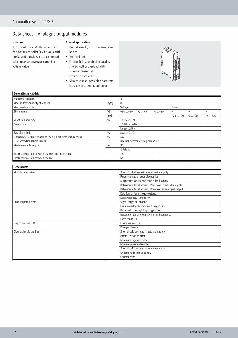
62 d Internet: www.festo.com/catalogue/... Subject to change – 2021/12
Automation system CPX-E
Data sheet – Analogue output modules
FunctionThe module converts the value speci-fied by the controller (15-bit value with prefix) and transfers it to a connected actuator as an analogue current or voltage value.
Area of application• Output signal (current/voltage) can
be set• Terminal strip• Electronic fuse protection against
short circuit or overload with automatic resetting
• Error display via LED• Slow response; possible short-term
increase in current requirement
General technical data
Number of outputs 4Max. address capacity of outputs [byte] 8Measured variable Voltage CurrentSignal range [V] –10 ... +10 –5 ... +5 0 ... +10 – – –
[mA] – – – –20 ... +20 0 ... +20 +4 ... +20Repetition accuracy [%] ±0.05 at 25°CData format 15 bits + prefix
Linear scalingBasic fault limit [%] ±0.1 at 25°COperating error limit related to the ambient temperature range [%] ±0.3Fuse protection (short circuit) Internal electronic fuse per moduleMaximum cable length [m] 30
ShieldedElectrical isolation between channel and internal bus YesElectrical isolation between channels No
General data
Module parameters Short circuit diagnostics for actuator supplyParameterisation error diagnosticsDiagnostics for undervoltage in load supplyBehaviour after short circuit/overload in actuator supplyBehaviour after short circuit/overload at analogue outputData format for analogue outputsDeactivate actuator supply
Channel parameters Signal range per channelEnable overload/short circuit diagnosticsEnable wire break/idling diagnosticsRelease for parameterisation error diagnosticsForce channel x
Diagnostics via LED Errors per moduleError per channel
Diagnostics via the bus Short circuit/overload in actuator supplyParameterisation errorNominal range exceededNominal range not reachedShort circuit/overload at analogue outputUndervoltage in load supplyGeneral error
Data sheet – Analogue output modules
Technical data
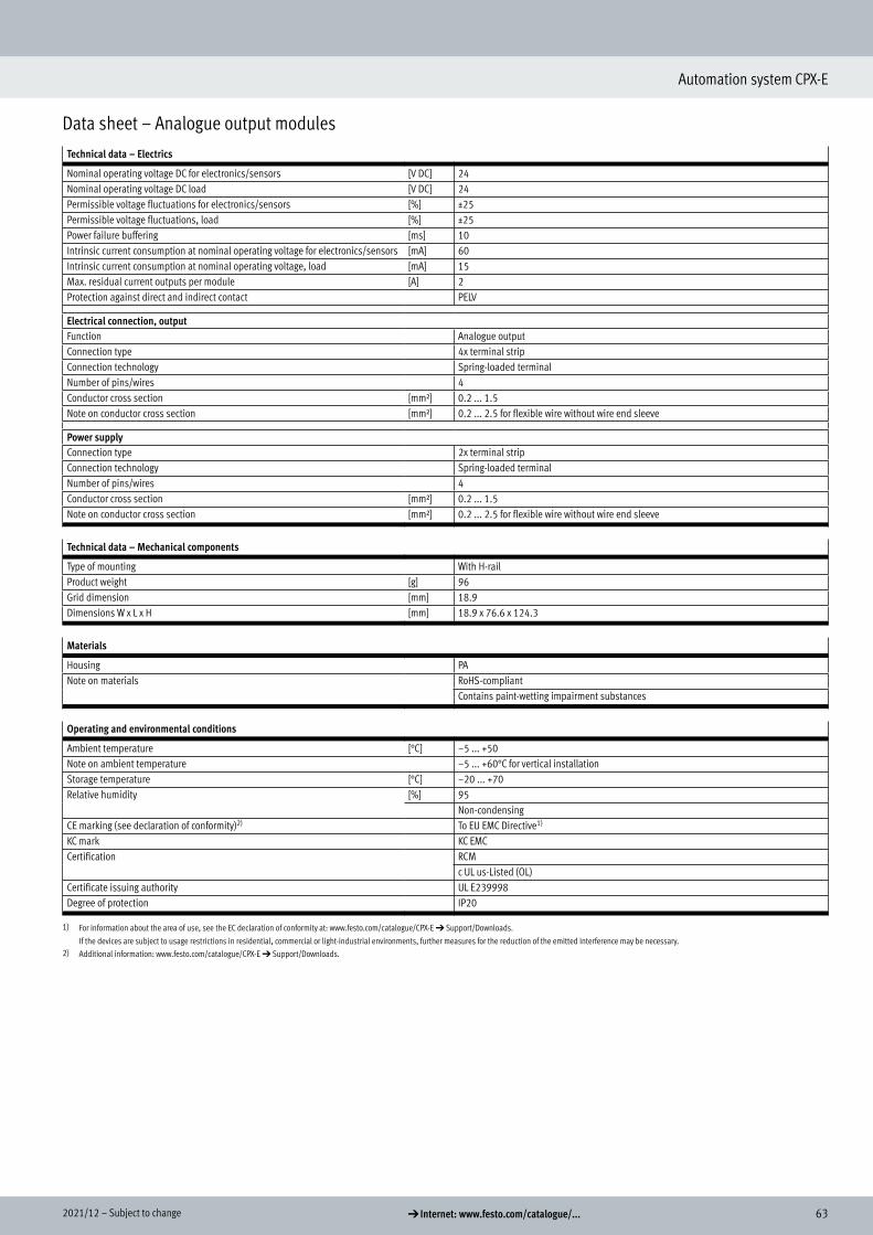
632021/12 – Subject to change d Internet: www.festo.com/catalogue/...
Automation system CPX-E
Data sheet – Analogue output modules
Technical data – Electrics
Nominal operating voltage DC for electronics/sensors [V DC] 24Nominal operating voltage DC load [V DC] 24Permissible voltage fluctuations for electronics/sensors [%] ±25Permissible voltage fluctuations, load [%] ±25Power failure buffering [ms] 10Intrinsic current consumption at nominal operating voltage for electronics/sensors [mA] 60Intrinsic current consumption at nominal operating voltage, load [mA] 15Max. residual current outputs per module [A] 2Protection against direct and indirect contact PELV
Electrical connection, outputFunction Analogue outputConnection type 4x terminal stripConnection technology Spring-loaded terminalNumber of pins/wires 4Conductor cross section [mm²] 0.2 ... 1.5Note on conductor cross section [mm²] 0.2 ... 2.5 for flexible wire without wire end sleeve
Power supplyConnection type 2x terminal stripConnection technology Spring-loaded terminalNumber of pins/wires 4Conductor cross section [mm²] 0.2 ... 1.5Note on conductor cross section [mm²] 0.2 ... 2.5 for flexible wire without wire end sleeve
Technical data – Mechanical components
Type of mounting With H-railProduct weight [g] 96Grid dimension [mm] 18.9Dimensions W x L x H [mm] 18.9 x 76.6 x 124.3
Materials
Housing PANote on materials RoHS-compliant
Contains paint-wetting impairment substances
Operating and environmental conditions
Ambient temperature [°C] –5 ... +50Note on ambient temperature –5 ... +60°C for vertical installationStorage temperature [°C] –20 ... +70Relative humidity [%] 95
Non-condensingCE marking (see declaration of conformity)2) To EU EMC Directive1)
KC mark KC EMCCertification RCM
c UL us-Listed (OL)Certificate issuing authority UL E239998Degree of protection IP20
1) For information about the area of use, see the EC declaration of conformity at: www.festo.com/catalogue/CPX-E d Support/Downloads.
If the devices are subject to usage restrictions in residential, commercial or light-industrial environments, further measures for the reduction of the emitted interference may be necessary.2) Additional information: www.festo.com/catalogue/CPX-E d Support/Downloads.

64 d Internet: www.festo.com/catalogue/... Subject to change – 2021/12
Automation system CPX-E
Data sheet – Analogue output modules
Safety characteristics
CE marking (see declaration of conformity) To EU EMC DirectiveShock resistance Shock test with severity level 1 to FN 942017-5 and EN 60068-2-27Vibration resistance Transport application test with severity level 1 to FN 942017-4 and EN 60068-2-6
Connection and display components
1
4
2
3
[1] Analogue outputs, 4 terminal strips each with one output
[2] 4 connections for functional earth (FE)
[3] Terminal strip for operating voltage supply
[4] LED indicators
Dimensions Download CAD data a www.festo.com
[1] Height with identification holder
B1 B2 H1 H2 H3 H4 L1 L2 L3
CPX-E-4AO-U-I 18.9 23.2 76.5 69.9 6 91.5 124.3 66 58.3
Connection and display components
Dimensions

652021/12 – Subject to change d Internet: www.festo.com/catalogue/...
Automation system CPX-E
Data sheet – Analogue output modules
Ordering data Part no. Type
Analogue output module with 4 outputs 4080494 CPX-E-4AO-U-I
Ordering data – AccessoriesPart no. Type
2
Identification holder, 5 pieces 4080500 CAFC-X3-C
Ordering data

66 d Internet: www.festo.com/catalogue/... Subject to change – 2021/12
Automation system CPX-E
Data sheet – IO-Link master modules
FunctionThe IO-Link master module establishes the connection to modules that have an IO-Link interface (device). The I/O data from the connected devices is transmitted to the connected CPX-E bus module and thus to the higher-order controller via fieldbus.
Area of application• Address space can be set• Terminal strip• Electronic fuse protection against
short circuit or overload with automatic resetting
• Error display via LED• Slow response; possible short-term
increase in current requirement
Application – Example configuration
The IO-Link master module provides 4 external IO-Link interfaces.As well as transmitting the communi-cation data, the IO-Link interfaces also transmit the power supply to the con-nected sensors and the load supply to the valves (or outputs). Both circuits are supplied separately with 24 V, using a separate reference potential.The load voltage supply is fed directly into the module.
The address space provided by the IO-Link master module to the IO-Link interfaces (ports) is set using DIL switches.It can be set from 2 ... 32 bytes per port. Since the address space for the module is limited to a total of 32 bytes, there is the following gradation:• For 2, 4 or 8 bytes per port, all
4 ports are active• For 16 bytes per port, 2 ports are
active• For 32 bytes per port, just 1 port is
activeThe behaviour of the master module is defined using parameters.
General technical data
Protocol IO-LinkIO-Link No. of ports 4
Port class BCommunication mode SIO, COM1 (4.8 kBaud), COM2 (38.4 kBaud), COM3 (230.4 kBaud)
Configurable via softwareCommunication C/Q green LEDMinimum cycle time Depending on minimally supported cycle time of connected IO-Link deviceProtocol version Master V 1.1Process data width IN [byte] 8 ... 32, parameterisableProcess data width OUT [byte] 8 ... 32, parameterisable
Fuse protection (short circuit) Internal electronic fuse, sensor for each moduleInternal electronic fuse, load per channel
Electrical isolation between channel and internal bus NoElectrical isolation between channels No
Data sheet – IO-Link master modules
Technical data
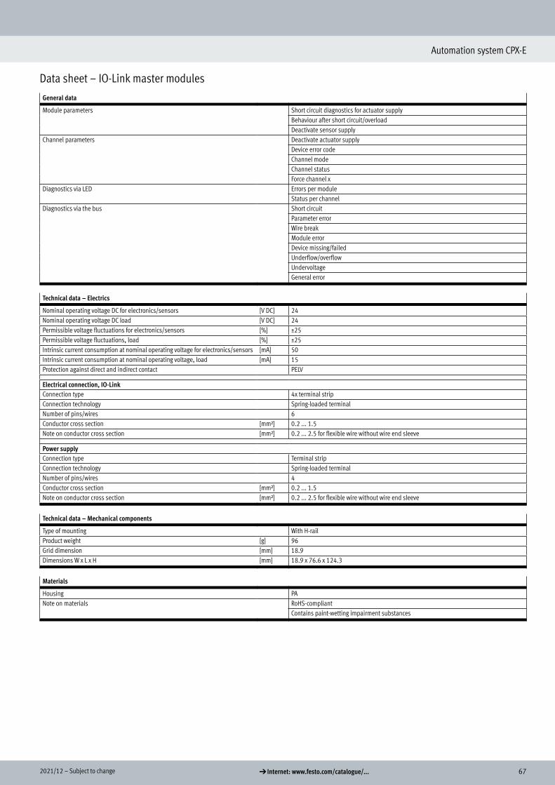
672021/12 – Subject to change d Internet: www.festo.com/catalogue/...
Automation system CPX-E
Data sheet – IO-Link master modules
General data
Module parameters Short circuit diagnostics for actuator supplyBehaviour after short circuit/overloadDeactivate sensor supply
Channel parameters Deactivate actuator supplyDevice error codeChannel modeChannel statusForce channel x
Diagnostics via LED Errors per moduleStatus per channel
Diagnostics via the bus Short circuitParameter errorWire breakModule errorDevice missing/failedUnderflow/overflowUndervoltageGeneral error
Technical data – Electrics
Nominal operating voltage DC for electronics/sensors [V DC] 24Nominal operating voltage DC load [V DC] 24Permissible voltage fluctuations for electronics/sensors [%] ±25Permissible voltage fluctuations, load [%] ±25Intrinsic current consumption at nominal operating voltage for electronics/sensors [mA] 50Intrinsic current consumption at nominal operating voltage, load [mA] 15Protection against direct and indirect contact PELV
Electrical connection, IO-LinkConnection type 4x terminal stripConnection technology Spring-loaded terminalNumber of pins/wires 6Conductor cross section [mm²] 0.2 ... 1.5Note on conductor cross section [mm²] 0.2 ... 2.5 for flexible wire without wire end sleeve
Power supplyConnection type Terminal stripConnection technology Spring-loaded terminalNumber of pins/wires 4Conductor cross section [mm²] 0.2 ... 1.5Note on conductor cross section [mm²] 0.2 ... 2.5 for flexible wire without wire end sleeve
Technical data – Mechanical components
Type of mounting With H-railProduct weight [g] 96Grid dimension [mm] 18.9Dimensions W x L x H [mm] 18.9 x 76.6 x 124.3
Materials
Housing PANote on materials RoHS-compliant
Contains paint-wetting impairment substances

68 d Internet: www.festo.com/catalogue/... Subject to change – 2021/12
Automation system CPX-E
Data sheet – IO-Link master modules
Operating and environmental conditions
Ambient temperature [°C] –5 ... +60Note on ambient temperature –5 ... 50°C for horizontal installationStorage temperature [°C] –20 ... +70Relative humidity [%] 95
Non-condensingCE marking (see declaration of conformity)2) To EU EMC Directive1)
KC mark KC EMCCertification RCM
c UL us-Listed (OL)Certificate issuing authority UL E239998Degree of protection IP20
1) For information about the area of use, see the EC declaration of conformity at: www.festo.com/catalogue/CPX-E d Support/Downloads.
If the devices are subject to usage restrictions in residential, commercial or light-industrial environments, further measures for the reduction of the emitted interference may be necessary.2) Additional information: www.festo.com/catalogue/CPX-E d Support/Downloads.
Safety characteristics
CE marking (see declaration of conformity) To EU EMC DirectiveShock resistance Shock test with severity level 1 to FN 942017-5 and EN 60068-2-27Vibration resistance Transport application test with severity level 1 to FN 942017-4 and EN 60068-2-6
Connection and display components
1
3
2
[1] IO-Link ports, 4 terminal strips each with one port
[2] Terminal strip for operating voltage supply, load voltage
[3] LED indicators
Connection and display components
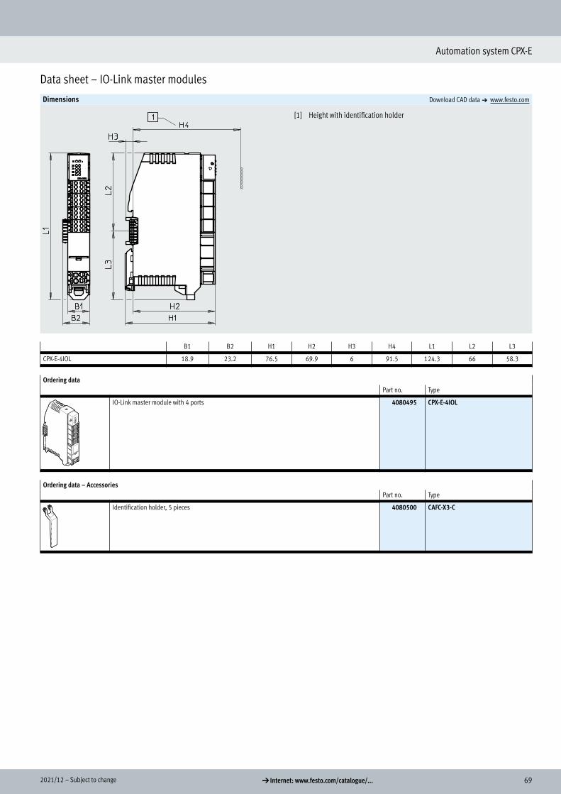
692021/12 – Subject to change d Internet: www.festo.com/catalogue/...
Automation system CPX-E
Data sheet – IO-Link master modules
Dimensions Download CAD data a www.festo.com
[1] Height with identification holder
B1 B2 H1 H2 H3 H4 L1 L2 L3
CPX-E-4IOL 18.9 23.2 76.5 69.9 6 91.5 124.3 66 58.3
Ordering data Part no. Type
IO-Link master module with 4 ports 4080495 CPX-E-4IOL
Ordering data – AccessoriesPart no. Type
2
Identification holder, 5 pieces 4080500 CAFC-X3-C
Dimensions
Ordering data

70 d Internet: www.festo.com/catalogue/... Subject to change – 2021/12
Automation system CPX-E
Ordering data – Modular product system
Ordering tableCondi-tions
Code Enter code
Module no. 5237644
Product type System CPX-E [1] 60E 60EElectrical control PROFIBUS bus module [1] -PB
PROFINET bus module [1] -PNEtherNet/IP bus module [1] -EPEtherCAT bus module [1] -ECController CODESYS V3, PROFINET [1] -CPNController CODESYS V3 with SoftMotion, PROFINET [1] -MPNController CODESYS V3, EtherNet/IP [1] -CEPController CODESYS V3 with SoftMotion, EtherNet/IP [1] -MEPController CODESYS V3 [1] -CBController CODESYS V3 with SoftMotion [1] -MB
Input/output modules Digital input module with 16 inputs [1] MDigital output module with 8 outputs [1] LAnalogue input module with 4 inputs (current/voltage) [1] NIAnalogue output module with 4 outputs (current/voltage) [1] NOIO-Link master module [1] T51Counter module [1] T53
Module configuration for IO-Link master module
DIL1 ... 8: OFF (64 bit consumption) 4 active ports,16-bit I/O per port OODIL 1: ON (128 bit consumption) 4 active ports, 32-bit I/O per port IODIL 2: ON (256 bit consumption) 4 active ports, 64-bit I/O per port OIDIL 1: ON, DIL 2: ON, DIL4: ON (256 bit consumption) 2 active ports, 128-bit I/O per port IIDIL 3: ON, DIL 5: ON (256 bit consumption) 1 active port, 256-bit I/O per port III
Accessories Module cover including label strips +MH32 GB memory card +SKDisplay and operating unit +AB
1) A maximum of one bus module or one controller and 10 input/output modules can be included.
Ordering table