TBT Deep Hole Drilling Tools, Accessories and Grinding ... a certified company in compliance with...
19
TBT Deep Hole Drilling Tools, Accessories and Grinding Machines
Transcript of TBT Deep Hole Drilling Tools, Accessories and Grinding ... a certified company in compliance with...
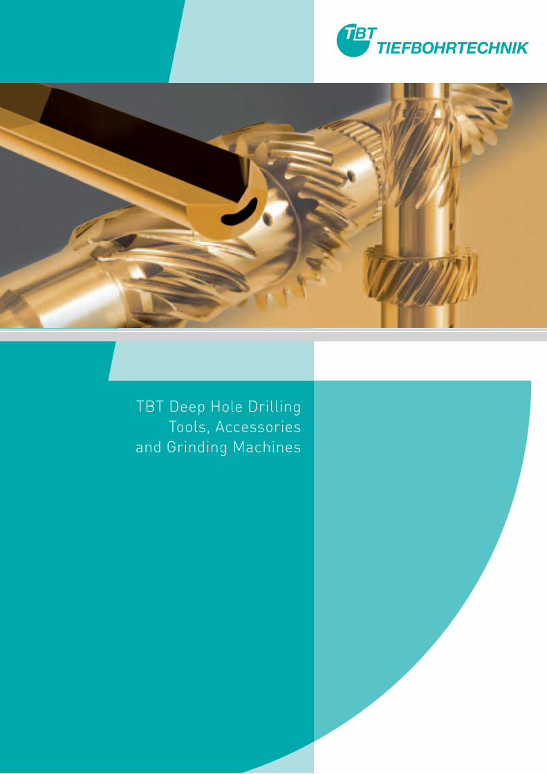
TBT Deep Hole DrillingTools, Accessories
and Grinding Machines

Across the world, our customers associate TBT Tiefbohrtechnik with reliability, quality, precision and customer proximity - and that for more than 40 years now.
The company has specialised in manufacturing technology for deep hole drilling since it was founded in Dettingen a.d. Erms in 1966. Our aim has always been to be an expert single-source provider of machines, tools and services.
Our rise to market leadership is confirmation that our customers acknowledge our corporate policy.
TBT Tiefbohrtechnik succeeds in combining the flexibility, dedication and customer-oriented approach of a lean, medium-sized enterprise with its presence on the global stage. We have subsidiaries or highly-experienced representatives in virtually all the major countries of the world. Your deep hole drilling requirements are safe in the hands of our highly-qualified, dedicated staff.
02 03
About us 2 Procedures 6Sealing case procedure 7 Immersion procedure 8 Procedures on machining centres 9
Tools 10Single-lip drill, brazed 10 Single-lip drill, solid carbide version 11 Cutting edge geometry 12 Contours 13 Double-lip drill 14
Special tools 14 High-speed tools 14 Step drill 15
Clamping sleeves (clamping elements) 16
Technical specifications 18 Surface quality 18 Runout 18 Cooling lubricants 19 Feed / cutting speed 19
Accessories 20 Drill bush 20 Drill bush holder 21 Sealing disc 22 Whip guide bush 23 Sealing case 24
Other accessories 25 Clamping cone 25 Tool holder 25 Tool setting device 26
Grinding machines 27 Universal grinding machine 27 Tandem grinding machine 27 Grinding device 27
Cutting data / reference values 28
Service 32 Repair service 32 Re-tipping, head 32 Re-tipping head/shank 32 Regrinding service 32 Coating service 32 Order form 33
Directions, contact 34
ABOUT US CONTENTS
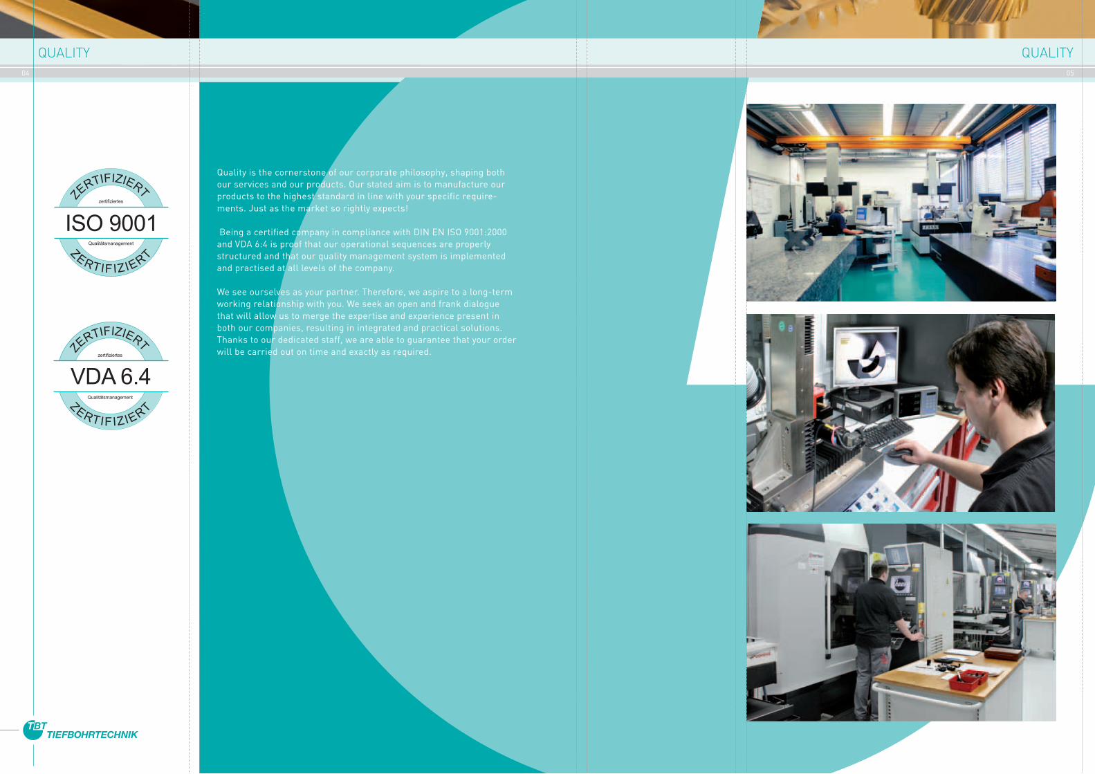
Quality is the cornerstone of our corporate philosophy, shaping both our services and our products. Our stated aim is to manufacture our products to the highest standard in line with your specific require-ments. Just as the market so rightly expects!
Being a certified company in compliance with DIN EN ISO 9001:2000 and VDA 6:4 is proof that our operational sequences are properly structured and that our quality management system is implemented and practised at all levels of the company.
We see ourselves as your partner. Therefore, we aspire to a long-term working relationship with you. We seek an open and frank dialogue that will allow us to merge the expertise and experience present in both our companies, resulting in integrated and practical solutions. Thanks to our dedicated staff, we are able to guarantee that your order will be carried out on time and exactly as required.
04 05ZE
RTIFIZIERT
ZERTIFIZIERT
zertifiziertes
Qualitätsmanagement
ISO 9001
zertifiziertes
Qualitätsmanagement
ZERTIFIZIERT
ZERTIFIZIERT
VDA 6.4
QUALITY QUALITY

TBT has been instrumental in shaping and developing deep hole technology. Thanks to the diameter tolerances it achieves, the surface quality and the minimum level of drift, the single-lip drill has proven its value in the area of high-performance precision drilling. In a number of applications, therefore, the deep hole drill principle replaces drilling and reaming with one pass. And it does so at a superior level of process reliability.
However, it doesn’t always have to be only deep hole drilling. With its combination of precision and superior drilling performance, the single-lip drill is also eminently suited to work on short and intricate holes.
Single-lip drills are single-edge tools that are guided through a drill bush during their initial drilling phase. These drills can be used not only for deep hole drilling machines but also, for example, for machi-ning centres or automatic lathes. The cooling lubricant moves from the machine to the tool cutting edge through the inside of the tool. In addition to cooling and lubricating the drill head, the pressurised lubricant flushes the chips out of the drill hole.
Deep hole drilling is, therefore, a reliable and efficient means of achieving precision drilling results.
TBT single-lip drills are manufactured to suit any drill diameter (1/1000 mm graduation) between 0.6 mm and far above 50 mm and for total lengths of up to approx. 6000 mm.
We develop and manufacture the tools to meet your requirements, taking into consideration the material to be drilled, the machinery to be used by the customer and the specific drilling situation. It may be a standard tool or one for counterboring existing holes, it may be a step tool for creating precise stepped bores with a minimum centre offset or a special tool for a specific bore surface; it may have no coating or may have a coating and, for high-end requirements, it may have a PCD-tipped tool cutting edge.
TBT is happy to advise you and to fulfil your drill head and shank requirements consistently and without delay, using state-of-the-art design and production procedures. The tool head and shank will be brazed to a clamping sleeve suitable for your machine.
TBT has hundreds of different clamping sleeves in stock at any one time. We also offer a 48-hour service.
HIGH-PERFORMANCE PRECISION DRILLING
06 07
SEALING CASE PROCEDURE
Work piece
Clamping cone
Clamping element
Chip box Sealing case
Sealing case
Whip guide bush
Tool steady restDrill bush holder
Drill bush
Carbide head
With the sealing case procedure, single-lip solid drill tools are used with a diameter range between 1.9 mm and approx. 50 mm. As the tool lengths can be up to 6000 mm, the tools are guided through steady rests. The clearances between the steady rests should be no wider than 40 – 50 x tool Ø.
The machine spindle is sealed by the sealing case or the sealing disc inside the case.
The cooling lubricant is supplied through one or more of the holes inside the tool.
The cooling lubricant / chip mixture is discharged through a longitudinal slot (bead) on the outside of the tool shank.
The cutting edge spans the radius of the hole to be drilled. The tool consists of the drill head, beaded shank and the clamping element (sleeve). The “classic” solid single-lip drill has a solid carbide head into which the cutting edge and the guide pads are ground.
PROCEDURE SEALING CASE PROCEDURE

Single-lip solid bore tools are used for the diameter range of 0.6 mm to 50 mm. As steady rests are not used, the drill depth in the immersion procedure is limited to a maximum of 160 mm.
This procedure is suited primarily for drilling shallow holes. Tools of less than 2 mm Ø are made entirely of carbide. Solid carbide tools are increasingly used for the diameter range between 2 mm and 12 mm and for relatively shallow drill depths.
The machine spindle is sealed by the immersion sleeve or the immersion spindle.
The cooling lubricant is supplied through one or more of the holes inside the tool. The cooling lubricant/chip mixture is discharged through a longitudinal slot (bead) on the outside of the tool shank.
The cutting edge spans the radius of the hole to be drilled. The tool consists of a drill head, a beaded shank and the clamping element (sleeve). The “classic” solid single-lip drill has a solid carbide head into which the cutting edge and the guide pads are ground.
IMMERSION PROCEDURE FOR SHALLOW DRILLING DEPTHS
08 09
The trend towards multi-station machining has resulted in single-lip drills being used increasingly on conventional machine tools, for example on machining centres. With its combination of precision and superior drilling performance, the single-lip drill is also used for short and intricate holes.
Unlike deep hole drilling machines, drill bushes are only very seldom used in conventional machine tools. As a result, a pilot hole has to be drilled in the work piece first if a single-lip drill is to be used.
This hole has to meet specific requirements, for example, regarding diameter tolerance or guide length. Our expert team at TBT will be happy to advise you on the appropriate tools from the TBT range, for example single-lip drill, step drill or solid carbide drill.
D_H
8
L = 1-1,5 x DWork piece
Cooling lubricant circuit
High-pressure pump
Filter
D
1st Pass | Pilot hole
2nd Pass | Deep hole drilling
IMMERSION PROCEDURE DEEP HOLE DRILLING ON MACHINING CENTRES
A Tool length B Drill depth C Reference dimension D Adjustment distance depending on drill diameter
A
B
C
D
90
Clamping cone
Tool
Drill bush Drill bush holderBase plate
Immersion sleeve
Tool setting device
Immersion spindle
Length calculation
Drill depth
Regrinding length
Chip removal length
Total length
Cylindrical end
Clamping element

10 11
Single-lip drills with a brazed drill head consist of a drill head made of solid carbide or steel with carbide inserts, a drill shank made of hardened and tem-pered steel and a steel clamping sleeve. The drill head and the clamping sleeve are brazed to the tool shank.
Diameter range 1.9 – 50.0 mmLength up to 6000 mmEffective tool length 40 – 50 x DCooling lubricant required: deep hole drilling oil preferredFilter resolution 10 – 20 μmViscosity Ø 1.9 – 50 mm = 10 – 20 mm² /S
The drill head and shank are made of a single carbide slug. This tool is particularly process reliable and efficient. A longer useful life is achieved due to the low level of torsional vibration.
The clamping element (steel) for this type of tool is made with a straightening pin. The clamping sleeves and drill shank are brazed together.
Diameter range 0.6 – 12.0 mmLength up to 350 mmEffective tool length 80 – 100 x DCooling lubricant required deep hole drilling oil preferredFilter resolution 5 – 10 μmViscosity Ø 0.6 – 2.0 mm = 7 – 10 mm² /S Ø 2.0 – 12 mm = 10 – 20 mm² /S
SOLID CARBIDE SINGLE-LIP DRILLS
Brazed joint
Clamping elementTool shankCarbide drill head
Brazed jointBrazed joint
Carbide drill head and shank
Straightening pinClamping element
SINGLE-LIP DRILL WITH BRAZED DRILL HEAD
Safety informationWe shall accept no liability for damage resulting from the improper handling of our deep hole drilling tools, from operating errors, deficient machine conditions or from the improper use of our tools. All relevant application, emission and safety guidelines and regulations must be observed.
We will be happy to advise you!
TOOLS: SINGLE-LIP DRILL, BRAZED TOOLS: SOLID CARBIDE SINGLE-LIP DRILLS

12 13
TOOLS: CUTTING EDGE GEOMETRY TOOLS: CONTOURS
Changes to the cutting edge geometry of the single-lip drill could affect the drilled surface, the chip shape, drilling tolerance, drill centring, chip removal, surface quality or useful life.
Virtually all drilling tasks can be executed successfully with TBT standard grind facets. Generally speaking, special grind facets, sometimes with a chip separator / chip breaker are required when deep drilling particularly long-chipping materials or materials that are difficult to machine. We already manufacture and develop a wide range of grind sections or manufacture them to customer specifications. The standard grind facets for TBT single-lip drills depend on the drill diameter and the material to be drilled. We recommend TBT universal and tandem grinding machines for regrinding tools.
Symbol Axis A Axis B Axis C Measure Comment
[There may be slight deviation in measurement due to angle distortion]
Twist the single-lip drill lightly around the circum-ference without damaging the guide chamfer!
Contour AThis is the preferred contour for narrow tolerances in terms of bore diameter and surface. Some of the guide pads are convex ground. The circular grinding chamfer can protrude over the guide pads.
Contour CContour for unfavourable drilling conditions when drilling or for cross-drilling. Machining soft materials or with a poorly-performing cooling lubricant. Is often used at the cylindrical guide part (long drill head).
Contour D45This contour is used almost exclusively for soft materials such as grey cast iron, graphite, .., particularly in connection with narrow bore tole-rances.
Contour G60Standard contour suitable for most materials and drilling jobs. With this contour, the tool diameter can no longer be measured after manufac-turing.The standard starting point for the guide pad is 60°, but can range from 45° to 80°.
TBT-developed contours are specially tailored to individual applications.
STANDARD CONTOURS
Contour S
Contour E185
Contour F
Contour GA80
CUTTING EDGE GEOMETRY
Set Axis C such that the chamfer during the second pass is parallel to the chip face. The width of the chamfer is the same as that of the circular grinding chamfer.
Twist the single-lip drill lightly around the circum-ference without damaging the guide chamfer!
[There may be slight deviation in measurement due to angle distortion]
Symbol Axis A Axis B Axis C Measure Comment
,3+0,2
20°30
°
~20°
12° 30° 25
°
20°
D/4
15°
1
53
4
6
12°
2
0
Standard grind section for single-lip drills with Ø = 5 to 30 mm
Changes to the cutting edge geometry will have a direct effect on bore quality and process reliability.
TBT cutting edge geometry is the result of over 40 years of research and development work by our machine engineering, tool design and machining service departments.
With our cutting edge geometries, no job is too difficult!
Make use of our experience for your drilling jobs!
D/4
15°
1
42
3
5
~30°
35°
30°
20° 40° 38
°
25°
Standard grind section for single-lip drills up to 5 mm
14 15
SPECIAL TOOLS: HIGH-SPEED SINGLE-LIP DRILL / DOUBLE-LIP DRILL SPECIAL TOOLS: STEP DRILL
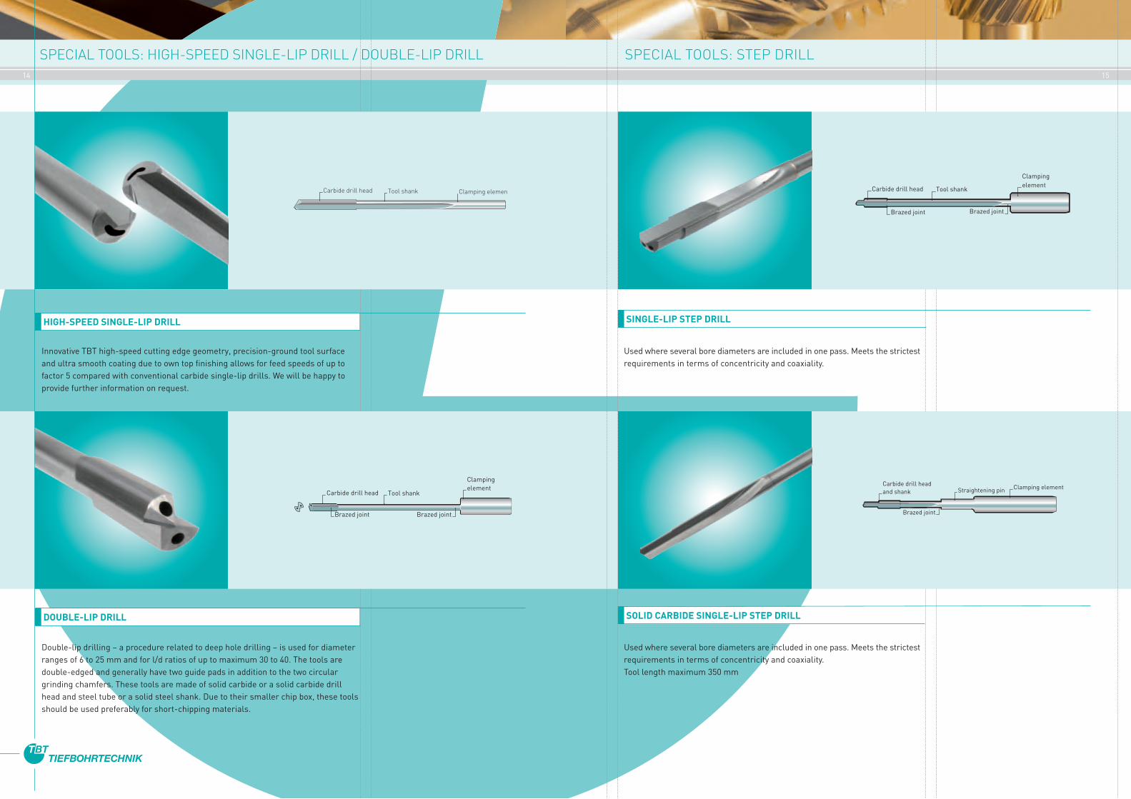
Innovative TBT high-speed cutting edge geometry, precision-ground tool surface and ultra smooth coating due to own top finishing allows for feed speeds of up to factor 5 compared with conventional carbide single-lip drills. We will be happy to provide further information on request.
Used where several bore diameters are included in one pass. Meets the strictest requirements in terms of concentricity and coaxiality.
Used where several bore diameters are included in one pass. Meets the strictest requirements in terms of concentricity and coaxiality.Tool length maximum 350 mm
Double-lip drilling – a procedure related to deep hole drilling – is used for diameter ranges of 6 to 25 mm and for l/d ratios of up to maximum 30 to 40. The tools are double-edged and generally have two guide pads in addition to the two circular grinding chamfers. These tools are made of solid carbide or a solid carbide drill head and steel tube or a solid steel shank. Due to their smaller chip box, these tools should be used preferably for short-chipping materials.
HIGH-SPEED SINGLE-LIP DRILL SINGLE-LIP STEP DRILL
DOUBLE-LIP DRILL SOLID CARBIDE SINGLE-LIP STEP DRILL
Clamping elementTool shankCarbide drill head
Brazed joint
Tool shankCarbide drill head
Brazed joint
Clamping element
Brazed joint
Straightening pin Clamping elementCarbide drill head and shank
Brazed jointBrazed joint
Clamping element
Tool shankCarbide drill head
16 17
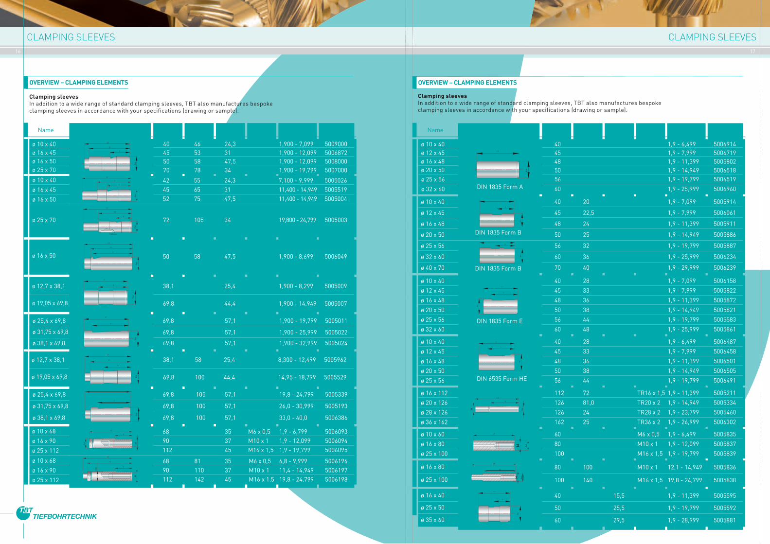
CLAMPING SLEEVES CLAMPING SLEEVES
X
Ø g
6
L1
L2ø 10 x 40ø 16 x 45ø 16 x 50ø 25 x 70
40 46 24,3 1,900 - 7,099 5009000 45 53 31 1,900 - 12,099 5006872 50 58 47,5 1,900 - 12,099 5008000 70 78 34 1,900 - 19,799 5007000
Article number
ø 10 x 40
ø 16 x 45
ø 16 x 50
Ø g
6
X
L1
L2
Paßfeder
Ø g
6
X
L1
L2
ø 25 x 70
42 55 24,3 7,100 - 9,999 5005026 45 65 31 11,400 - 14,949 5005519 52 75 47,5 11,400 - 14,949 5005004
72 105 34 19,800 - 24,799 5005003
Ø g
6
X
L1
L2
ø 16 x 50 50 58 47,5 1,900 - 8,699 5006049
Ø g
6
L1
X
L1
Ø g
6
X
L2
Ø g
6
L2
X
OVERVIEW – CLAMPING ELEMENTS
Clamping sleevesIn addition to a wide range of standard clamping sleeves, TBT also manufactures bespoke clamping sleeves in accordance with your specifications (drawing or sample).
Name Diagram L1 L2 X M Drill range
L1
Ø g
6
X
X
L1
Ø g
6
M
X
L1
M
Ø g
6
L2
ø 12,7 x 38,1 38,1 25,4 1,900 - 8,299 5005009
ø 19,05 x 69,8 69,8 44,4 1,900 - 14,949 5005007
ø 25,4 x 69,8 69,8 57,1 1,900 - 19,799 5005011
ø 31,75 x 69,8 69,8 57,1 1,900 - 25,999 5005022
ø 38,1 x 69,8 69,8 57,1 1,900 - 32,999 5005024
ø 12,7 x 38,1 38,1 58 25,4 8,300 - 12,499 5005962
ø 19,05 x 69,8 69,8 100 44,4 14,95 - 18,799 5005529
ø 25,4 x 69,8 69,8 105 57,1 19,8 - 24,799 5005339
ø 31,75 x 69,8 69,8 100 57,1 26,0 - 30,999 5005193
ø 38,1 x 69,8 69,8 100 57,1 33,0 - 40,0 5006386
ø 10 x 68
ø 16 x 90
ø 25 x 112
68 35 M6 x 0,5 1,9 - 6,799 5006093 90 37 M10 x 1 1,9 - 12,099 5006094 112 45 M16 x 1,5 1,9 - 19,799 5006095 ø 10 x 68
ø 16 x 90
ø 25 x 112
68 81 35 M6 x 0,5 6,8 - 9,999 5006196 90 110 37 M10 x 1 11,4 - 14,949 5006197 112 142 45 M16 x 1,5 19,8 - 24,799 5006198
ø 10 x 40ø 12 x 45ø 16 x 48ø 20 x 50
40 1,9 - 6,499 5006914 45 1,9 - 7,999 5006719 48 1,9 - 11,399 5005802 50 1,9 - 14,949 5006518 56 1,9 - 19,799 5006519
60 1,9 - 25,999 5006960
OVERVIEW – CLAMPING ELEMENTS
Clamping sleevesIn addition to a wide range of standard clamping sleeves, TBT also manufactures bespoke clamping sleeves in accordance with your specifications (drawing or sample).
ø 25 x 56
ø 32 x 60
Ø h
6
L1
DIN 1835 Form A
40 20 1,9 - 7,099 5005914
45 22,5 1,9 - 7,999 5006061
48 24 1,9 - 11,399 5005911
50 25 1,9 - 14,949 5005886
56 32 1,9 - 19,799 5005887
60 36 1,9 - 25,999 5006234
70 40 1,9 - 29,999 5006239
Ø h
6
X
DIN 1835 Form B
ø 10 x 40
ø 12 x 45
ø 16 x 48
ø 20 x 50
ø 25 x 56
ø 32 x 60
ø 40 x 70
Øh6
X
L1
DIN 1835 Form B
40 28 1,9 - 7,099 5006158
45 33 1,9 - 7,999 5005822
48 36 1,9 - 11,399 5005872
50 38 1,9 - 14,949 5005821
56 44 1,9 - 19,799 5005583
60 48 1,9 - 25,999 5005861
ø 10 x 40
ø 12 x 45
ø 16 x 48
ø 20 x 50
ø 25 x 56
ø 32 x 60
L1
Øh6
X
DIN 1835 Form E
40 28 1,9 - 6,499 5006487
45 33 1,9 - 7,999 5006458
48 36 1,9 - 11,399 5006501
50 38 1,9 - 14,949 5006505
56 44 1,9 - 19,799 5006491
ø 10 x 40
ø 12 x 45
ø 16 x 48
ø 20 x 50
ø 25 x 56
Øh6
X
L1
DIN 6535 Form HE
112 72 TR16 x 1,5 1,9 - 11,399 5005211
126 81,0 TR20 x 2 1,9 - 14,949 5005334
126 24 TR28 x 2 1,9 - 23,799 5005460
162 25 TR36 x 2 1,9 - 26,999 5006302
ø 16 x 112
ø 20 x 126
ø 28 x 126
ø 36 x 162
Øg6M
L1
X
ø 10 x 60
ø 16 x 80
ø 25 x 100
60 M6 x 0,5 1,9 - 6,499 5005835
80 M10 x 1 1,9 - 12,099 5005837
100 M16 x 1,5 1,9 - 19,799 5005839
M
L1
Øg6
ø 16 x 80
ø 25 x 100
80 100 M10 x 1 12,1 - 14,949 5005836
100 140 M16 x 1,5 19,8 - 24,799 5005838
L2
L1
Øg6M
ø 16 x 40
ø 25 x 50
ø 35 x 60
40 15,5 1,9 - 11,399 5005595
50 25,5 1,9 - 19,799 5005592
60 29,5 1,9 - 28,999 5005881
L1
Øg6
X
Article number Name Diagram L1 L2 X M Drill range

18 19
TECHNICAL SPECIFICATIONS TECHNICAL SPECIFICATIONS
Surface quality (reference values)
1,4
1,2
1,0
0,8
0,6
0,4
0,2
0
Runoutin mm
0 500 1000 Drilling depth in mm
Stationary work piece
Counter-rotating work piece
Runout (reference values)
Diameter toleranceDiameter tolerances of up to IT 7 can be achieved in production with TBT single-lip drills.
RUNOUT
As a result of the drill bush or the pilot bore on the work piece together with the bore itself, the single-lip drill achieves precision, restricted guidance, and the drift is, therefore, kept to a minimum.
Drill Ø in mm
0 5 10 15 20 25 30
0
0,05
0,1
0,15
0,2
0,25
0,3
0,35
0,4
Aluminium alloy, non-ferrous metals
Tempered steel
Case-hardened steel
Titanium, Nickel, Inconell, Hasteloy
Cast aluminium
Grey cast iron
Nitriding steel and heat/corrosion-resistant steels
0
Coolant pressure in bar
Drill Øin mm
4 5 6 7 8 9 10 12 15 20 25 30
Cooling lubricant quantity in l/min
120
100
0
80
60
40
20
Cutting speed in m/min
Cast aluminium
Grey cast iron
Nitriding steel
Heat / corrosion-resistant steels
Aluminium alloy, non-ferrous metals
Tempered steel
Case-hardened steel
Titanium, Nickel, Inconell, Hasteloy
0 20 40 60 80 100 120 140 160 180
Cooling lubricants (reference values)
Feed (reference values)Cutting speed (reference values)
Title
Twist drilling
Reaming
Broaching
Honing
Deep hole drilling
Arithmetical mean roughness Ra
SURFACE QUALITY
The radial energy generated during drilling is transferred to the bore wall through the guide pads, resulting in the surface being pressed smooth.
This effect can be increased even more by adjusting the design of the guide pads, giving an outstanding surface quality.
CUTTING SPEED
Please see the tables on pages 28 – 31 for details of the various cutting speeds and feed values (see also virtual speed calculator at www.tbt.de).
COOLING LUBRICANTS
An efficient and correctly dimensioned coolant system and filter are required in order to ensure the economic viability and process reliability of deep hole drilling. A further consideration is the requirement to adhere to a minimum level of fat content (depending on the material) when using emulsion. We recommend the use of deep hole drilling oil for small drill diameters and high-alloy steels.

20 21
ACCESSORIES: DRILL BUSHES ACCESSORIES: DRILL BUSH HOLDER
DRILL BUSHES STEEL / CARBIDE VERSION
TBT standard steel/carbide
TBN 2302/2310 0,900 0,999 3 8TBN 2302/2310 1,000 1,899 4 TBN 2302/2310 1,900 2,699 5 TBN 2302/2310 2,700 3,399 6 11 TBN 2302/2310 3,400 4,099 7 TBN 2302/2310 4,100 5,099 8 TBN 2302/2310 5,100 6,099 10 14 TBN 2302/2310 6,100 8,099 12 TBN 2302/2310 8,100 10,099 15 18 TBN 2302/2310 10,100 12,099 18 TBN 2302/2310 12,100 15,099 22 26 TBN 2302/2310 15,100 18,099 26 TBN 2302/2310 18,100 22,099 30 33 TBN 2302/2310 22,100 26,099 35 TBN 2302/2310 26,100 30,099 42 TBN 2302/2310 30,100 35,099 48 42 TBN 2302/2310 35,100 42,099 55 TBN 2302/2310 42,100 48,099 62 52 TBN 2302/2310 48,100 55,099 70 TBN 2302/2310 55,100 63,000 78 67
Tool-ø D n6 L ø G6
Please note when ordering:Example of order: drill bush Ø 5.0 steelOrder text: drill bush as per TBN 2302 5.0 x 8 x11
Machining accessories, drill bushCentring guide at the start of drilling until the tool centres itself in the hole. Available in steel or carbide.
Drill rangefrom to
1,000 1,899 4 1,900 2,699 5 2,700 3,399 6 3,400 4,099 7 4,100 5,099 8 5,100 6,099 10 6,100 8,099 12 8,100 10,099 15 10,100 12,099 18 12,100 15,099 22 15,100 18,099 26 18,100 22,099 30 22,100 26,099 35 26,100 30,099 42 30,100 35,099 48 35,100 42,099 55 42,100 48,099 62 48,100 55,099 70 55,100 63,000 78
øD
Machining accessories, drill bush holderHolds the drill bush in place for positioning on the work piece.
Please note when ordering:Please state the machine number and drill diameter when ordering.
DRILL BUSH HOLDER
Ø G
6
Ø D
n6
L Ø 16D
D1
Drill bush holder
D
D1
Please state tool Ø when ordering.

22 23
ACCESSORIES: SEALING DISCS
TBT standard
TBN 5404 2,900 5,249 20 7 TBN 5404 5,250 14,449 32 11 TBN 5404 14,450 25,999 40 12 TBN 5404 26,000 40,999 90 12
Tool Ø d2 b d
Please state tool Ø
when ordering.
COMPOSITE SEALING DISC TBN 5404
TBT standard
TBN 5416 3,100 - 15,599 32 4 TBN 5416 15,600 - 25,999 40 4 TBN 5416 from 26,000 90 4
Tool Ø D b d
Please state tool Ø
when ordering.
VULKOLLAN SEALING DISC TBN 5416
Machining accessories, sealing discForms a seal between the chip box and the spindle
Sealing disc TBN 5404
Sealing disc TBN 5416
d
120°
b
D
Sealing disc glued to deflector
Deflector
Sealing disc d2
b
d
Whip guide bush
Form whip guide bush
ØD
1
L
ØD
L1
Ød
120°
Machining accessories, whip guide bushFor guiding and stabilising the tool
ØD
1
L
ØD
L1
Ød
TBT standard Tool Ø D D1 L L1 d
Please state tool Ø
when ordering.
WHIP GUIDE BUSHES
TBN 5406 1,900 - 16,399 20 26 20 12 TBN 5407 1,900 - 25,999 30 38 26 16 TBN 5412 1,900 - 34,000 45 50 26 16
Please state tool Ø
when ordering.
FORM WHIP GUIDE BUSHES
TBN 5420 3,900 - 12,390 20 26 20 12 TBN 5421 4,200 - 22,799 30 38 26 16
ACCESSORIES: WHIP GUIDE BUSHES
TBT standard Tool Ø D D1 L L1 d
24 25
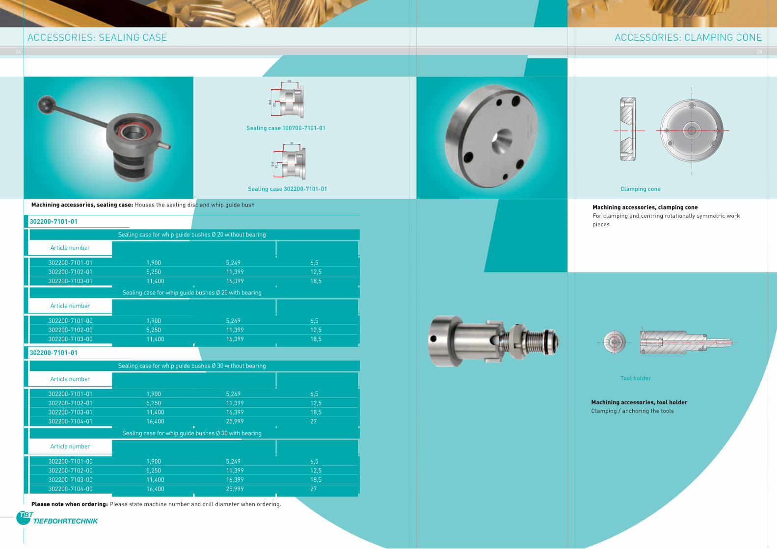
ACCESSORIES: SEALING CASE ACCESSORIES: CLAMPING CONE
Sealing case 100700-7101-01
Sealing case 302200-7101-01
38
ØDØ
60
38
ØDØ
60
Machining accessories, clamping coneFor clamping and centring rotationally symmetric work pieces
Clamping cone
Machining accessories, tool holder Clamping / anchoring the tools
302200-7101-01 1,900 5,249 6,5 302200-7102-01 5,250 11,399 12,5 302200-7103-01 11,400 16,399 18,5
Article number
302200-7101-01
Sealing case for whip guide bushes Ø 20 without bearing
Drill rangefrom to øD
302200-7101-00 1,900 5,249 6,5 302200-7102-00 5,250 11,399 12,5 302200-7103-00 11,400 16,399 18,5
Article number
Sealing case for whip guide bushes Ø 20 with bearing
Drill rangefrom to øD
302200-7101-01 1,900 5,249 6,5 302200-7102-01 5,250 11,399 12,5 302200-7103-01 11,400 16,399 18,5 302200-7104-01 16,400 25,999 27
Article number
302200-7101-01
Sealing case for whip guide bushes Ø 30 without bearing
Drill rangefrom to øD
302200-7101-00 1,900 5,249 6,5 302200-7102-00 5,250 11,399 12,5 302200-7103-00 11,400 16,399 18,5 302200-7104-00 16,400 25,999 27
Article number
Sealing case for whip guide bushes Ø 30 with bearing
Drill rangefrom to øD
Machining accessories, sealing case: Houses the sealing disc and whip guide bush
Please note when ordering: Please state machine number and drill diameter when ordering.
Tool holder

26 27
OTHER ACCESSORIES: TOOL SETTING DEVICE GRINDING MACHINES
The length measuring device is a precision instrument for setting the drill length. The above illustration shows the length measuring device and its components.
The adaptor (4) holds the plug gauge and the drill to be measured. In the case of greater lengths, the drills are supported by the sliding V-blocks which are height-adjustable and can be locked.
The sliding carrier plate (9) with mounted magnetic sensor determines the zero point and measures the length. The measurement is displayed at the position indicator (7). The incline of the position indicator is adjustable and can be adapted to the lighting conditions and the height of the operator.
The cable connecting the magnetic sensor to the position indicator is enclosed in a cable drag chain (15).
The measuring length can be extended by moving the stop plate (8) to the end of the sliding carrier plate (9).
While we supply different versions of the length measuring device, the description and operation of the devices are essentially the same.
» table-top version » stand-alone version with base, drill support and plastic boxes for small parts
1 Base holder2 Support bolt3 Holder for adaptor4 Adaptor5 Plug gauge6 V-blocks7 Position indicator8 Stop plate9 Moving carrier plate10 Magnetic sensor11 Magnetic tape12 Linear guide13 Supports14 Fastening screws15 Cable drag chain
Grinding machineOur wide variety of re-sharpening devices enables you to regrind your single-lip drills yourself. Our many years of experience in this field have informed the design and manufac-ture of our grinding machines, devices and associated accessories.
Tandem grinding machineA high-precision, double-spindle grinding machine designed for precision re-sharpening of larger-series single-lip drills with the same cutting edge geometry and a diameter range of 2.0 mm to approx. 20 mm.
Up to five different tool positions allow for all angles required for five-facet grinding to be re-set, making grinding even simpler. The lateral oscillation of the spindle unit is electromechanical.
» Cutting edge geometry only has to be set once» Fully replaceable adaptor for different geometries and for setting the geometries» Eight different tool holder cassettes cover the entire range of tool diameters
A further accessory available is the dry dust extractor for efficient removal of any grinding dust in the work area.
TBT Universal clamping deviceOur universal clamping device can be used on all conventional tool grinding machines. The benefits of the clamping device used on our TBT universal grinding machine speak for themselves:
» Compact device, adjustable in three axes for grinding of all standard geometries for single-lip drills
» Device for supporting particularly long single-lip drills» Two different clamping ranges [2.5 – 32 mm and 5.0 – 45 mm] cover a broad spectrum of tool diameters.
In addition, our TBT universal clamping device can be fitted with a grinder holder with integrated lighting and 20x mea-surement microscope, for optimum re-sharpening of your very small single-lip drills (1.0 –3.5 mm).
TBT universal grinding machineA ready-to-operate machine for your specific requirements: the grinding spindle unit and our tried-and-tested TBT universal clamping device are mounted together on a solid plate, allowing for optimum regrinding quality for excellent drill results. A matching base and extraction unit are also available.
General view of length measuring device
9
1 Grundhalter
2 Auflagebolzen
3 Halter für Adapter
4 Adapter
5 Lehrdorn
6 Prismen
7 Positionsanzeige
8 Anschlagplatte
9 Schiebeschlitten
10 Magnetsensor
11 Magnetband
12 Linearführung
13 Unterstützungen
14 Befestigungsschrauben
15 Energiekette
7
1210
X
7
6654
3 82
1
13
13
11
14
14
15
9
1 Grundhalter
2 Auflagebolzen
3 Halter für Adapter
4 Adapter
5 Lehrdorn
6 Prismen
7 Positionsanzeige
8 Anschlagplatte
9 Schiebeschlitten
10 Magnetsensor
11 Magnetband
12 Linearführung
13 Unterstützungen
14 Befestigungsschrauben
15 Energiekette
7
1210
X
7
6654
3 82
1
13
13
11
14
14
15
Tandem grinding machine Universal grinding machine
MACHINING ACCESSORIES, TOOL SETTING DEVICE
28 29
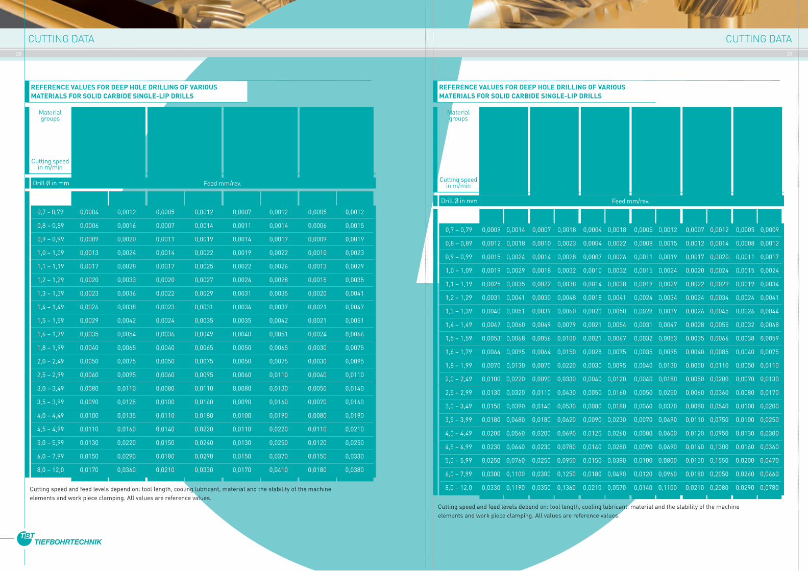
CUTTING DATA CUTTING DATA
REFERENCE VALUES FOR DEEP HOLE DRILLING OF VARIOUS MATERIALS FOR SOLID CARBIDE SINGLE-LIP DRILLS
Material groups
Cutting speed in m/min
Spring steels, hardened steels, high-temperature steels, cast steel / chilled
cast iron, Special alloys, e.g. Nimonic, Inconel,
titanium, titanium alloys
25 – 60
Stainless, acid-resistant steel + cast steel,
austenitic 18 – 25% Cr, Ni > 8%
30 – 60
Stainless steel + cast steel, martensitic /
ferritic 13 – 25% (sulphurated) “good
machinability”
40 – 70
Alloyed tempered steels, case-hardened steels,
nitriding steels, tool steels, (> 900N/mm²)
60 – 80
Drill Ø in mm Feed mm/rev.
from to from to from to from to
0,7 - 0,79 0,0004 0,0012 0,0005 0,0012 0,0007 0,0012 0,0005 0,0012
0,8 – 0,89 0,0006 0,0016 0,0007 0,0014 0,0011 0,0014 0,0006 0,0015
0,9 – 0,99 0,0009 0,0020 0,0011 0,0019 0,0014 0,0017 0,0009 0,0019
1,0 – 1,09 0,0013 0,0024 0,0014 0,0022 0,0019 0,0022 0,0010 0,0023
1,1 – 1,19 0,0017 0,0028 0,0017 0,0025 0,0022 0,0026 0,0013 0,0029
1,2 – 1,29 0,0020 0,0033 0,0020 0,0027 0,0024 0,0028 0,0015 0,0035
1,3 – 1,39 0,0023 0,0036 0,0022 0,0029 0,0031 0,0035 0,0020 0,0041
1,4 – 1,49 0,0026 0,0038 0,0023 0,0031 0,0034 0,0037 0,0021 0,0047
1,5 – 1,59 0,0029 0,0042 0,0024 0,0035 0,0035 0,0042 0,0021 0,0051
1,6 – 1,79 0,0035 0,0054 0,0036 0,0049 0,0040 0,0051 0,0024 0,0066
1,8 – 1,99 0,0040 0,0065 0,0040 0,0065 0,0050 0,0065 0,0030 0,0075
2,0 – 2,49 0,0050 0,0075 0,0050 0,0075 0,0050 0,0075 0,0030 0,0095
2,5 – 2,99 0,0060 0,0095 0,0060 0,0095 0,0060 0,0110 0,0040 0,0110
3,0 – 3,49 0,0080 0,0110 0,0080 0,0110 0,0080 0,0130 0,0050 0,0140
3,5 – 3,99 0,0090 0,0125 0,0100 0,0160 0,0090 0,0160 0,0070 0,0160
4,0 – 4,49 0,0100 0,0135 0,0110 0,0180 0,0100 0,0190 0,0080 0,0190
4,5 – 4,99 0,0110 0,0160 0,0140 0,0220 0,0110 0,0220 0,0110 0,0210
5,0 – 5,99 0,0130 0,0220 0,0150 0,0240 0,0130 0,0250 0,0120 0,0250
6,0 – 7,99 0,0150 0,0290 0,0180 0,0290 0,0150 0,0370 0,0150 0,0330
8,0 – 12,0 0,0170 0,0360 0,0210 0,0330 0,0170 0,0410 0,0180 0,0380
Cutting speed and feed levels depend on: tool length, cooling lubricant, material and the stability of the machine elements and work piece clamping. All values are reference values.
REFERENCE VALUES FOR DEEP HOLE DRILLING OF VARIOUS MATERIALS FOR SOLID CARBIDE SINGLE-LIP DRILLS
Material groups
Cutting speed in m/min
Cast iron, grey cast iron
(> 300 N/mm²), ductile cast iron (> 400 N/mm²), general steel
casting
60 – 90
Drill Ø in mm Feed mm/rev.
Cutting speed and feed levels depend on: tool length, cooling lubricant, material and the stability of the machine elements and work piece clamping. All values are reference values.
0,7 – 0,79 0,0009 0,0014 0,0007 0,0018 0,0004 0,0018 0,0005 0,0012 0,0007 0,0012 0,0005 0,0009
0,8 – 0,89 0,0012 0,0018 0,0010 0,0023 0,0004 0,0022 0,0008 0,0015 0,0012 0,0014 0,0008 0,0012
0,9 – 0,99 0,0015 0,0024 0,0014 0,0028 0,0007 0,0026 0,0011 0,0019 0,0017 0,0020 0,0011 0,0017
1,0 – 1,09 0,0019 0,0029 0,0018 0,0032 0,0010 0,0032 0,0015 0,0024 0,0020 0,0024 0,0015 0,0024
1,1 – 1,19 0,0025 0,0035 0,0022 0,0038 0,0014 0,0038 0,0019 0,0029 0,0022 0,0029 0,0019 0,0034
1,2 – 1,29 0,0031 0,0041 0,0030 0,0048 0,0018 0,0041 0,0024 0,0034 0,0024 0,0034 0,0024 0,0041
1,3 – 1,39 0,0040 0,0051 0,0039 0,0060 0,0020 0,0050 0,0028 0,0039 0,0026 0,0045 0,0026 0,0044
1,4 – 1,49 0,0047 0,0060 0,0049 0,0079 0,0021 0,0054 0,0031 0,0047 0,0028 0,0055 0,0032 0,0048
1,5 – 1,59 0,0053 0,0068 0,0056 0,0100 0,0021 0,0067 0,0032 0,0053 0,0035 0,0066 0,0038 0,0059
1,6 – 1,79 0,0064 0,0095 0,0064 0,0150 0,0028 0,0075 0,0035 0,0095 0,0040 0,0085 0,0040 0,0075
1,8 – 1,99 0,0070 0,0130 0,0070 0,0220 0,0030 0,0095 0,0040 0,0130 0,0050 0,0110 0,0050 0,0110
2,0 – 2,49 0,0100 0,0220 0,0090 0,0330 0,0040 0,0120 0,0040 0,0180 0,0050 0,0200 0,0070 0,0130
2,5 – 2,99 0,0130 0,0320 0,0110 0,0430 0,0050 0,0160 0,0050 0,0250 0,0060 0,0360 0,0080 0,0170
3,0 – 3,49 0,0150 0,0390 0,0140 0,0530 0,0080 0,0180 0,0060 0,0370 0,0080 0,0540 0,0100 0,0200
3,5 – 3,99 0,0180 0,0480 0,0180 0,0620 0,0090 0,0230 0,0070 0,0490 0,0110 0,0750 0,0100 0,0250
4,0 – 4,49 0,0200 0,0560 0,0200 0,0690 0,0120 0,0260 0,0080 0,0600 0,0120 0,0950 0,0130 0,0300
4,5 – 4,99 0,0230 0,0640 0,0230 0,0780 0,0140 0,0280 0,0090 0,0690 0,0140 0,1300 0,0160 0,0360
5,0 – 5,99 0,0250 0,0760 0,0250 0,0950 0,0150 0,0380 0,0100 0,0800 0,0150 0,1550 0,0200 0,0470
6,0 – 7,99 0,0300 0,1100 0,0300 0,1250 0,0180 0,0490 0,0120 0,0960 0,0180 0,2050 0,0260 0,0660
8,0 – 12,0 0,0330 0,1190 0,0350 0,1360 0,0210 0,0570 0,0140 0,1100 0,0210 0,2080 0,0290 0,0780
from to from to from to from to from to from to
Non-alloy and low-alloy
structural steel, machining steel, tempered steel, case hardened steel, tool steel (< 900N/mm²),
“good machina-bility”
70 – 100
Copper, bronze, brass, plastics
80 – 150
Aluminium + cast aluminium Si content > 5%, “good machina-
bility”
80 – 160
Aluminium + aluminium alloy Si content < 5%, “not hardened”
100 – 300
Cast iron, grey cast iron (< 300 N/mm²), ductile
cast iron (< 400 N/mm²), malleable cast iron, white-heart malleable iron, blackheart malleable iron, “good machina-
bility”
70 – 100

30 31
CUTTING DATA CUTTING DATA
REFERENCE VALUES FOR DEEP HOLE DRILLING OF VARIOUS MATERIALS FOR SINGLE-LIP DRILLS WITH BRAZED-ON CARBIDE HEAD
Material groups
Cutting speed in m/min
Spring steels, hardened steels, high-temperature steels, cast steel / chilled
cast iron , Special alloys, e.g. Nimonic, Inconel,
titanium, titanium alloys
25 – 60
Stainless, acid-resistant steel + cast steel,
austenitic 18 – 25% Cr, Ni > 8%
30 – 60
Stainless steel + cast steel, martensitic /
ferritic 13 – 25% (sulphurated) “easily
machinable”
40 – 70
Alloyed tempered steels, case-hardened steels,
nitriding steels, tool steels, (> 900N / mm²)
60 – 80
Drill Ø in mm Feed mm/rev.
from to from to from to from to
1,9 – 2,49 0,001 0,002 0,002 0,005 0,002 0,006 0,002 0,005
2,5 – 2,99 0,001 0,005 0,004 0,007 0,004 0,007 0,004 0,006
3,0 – 3,49 0,002 0,007 0,006 0,008 0,005 0,009 0,005 0,007
3,5 – 3,99 0,004 0,008 0,008 0,009 0,007 0,011 0,007 0,010
4,0 – 4,49 0,006 0,009 0,009 0,010 0,008 0,013 0,008 0,012
4,5 – 4,99 0,008 0,011 0,010 0,013 0,009 0,017 0,011 0,015
5,0 – 5,99 0,010 0,014 0,012 0,015 0,013 0,019 0,013 0,018
6,0 – 6,99 0,012 0,016 0,014 0,017 0,015 0,023 0,015 0,022
7,0 – 7,99 0,015 0,018 0,016 0,019 0,018 0,026 0,018 0,025
8,0 – 8,99 0,018 0,021 0,018 0,021 0,020 0,031 0,020 0,027
9,0 – 9,99 0,021 0,025 0,020 0,028 0,023 0,034 0,023 0,030
10,0 – 11,99 0,024 0,030 0,025 0,033 0,025 0,041 0,025 0,038
12,0 – 13,99 0,027 0,033 0,030 0,038 0,030 0,045 0,029 0,044
14,0 – 15,99 0,029 0,040 0,035 0,044 0,035 0,052 0,035 0,050
16,0 – 17,99 0,033 0,044 0,041 0,050 0,042 0,060 0,039 0,053
18,0 – 19,99 0,037 0,049 0,045 0,062 0,045 0,067 0,044 0,060
20,0 – 23,99 0,041 0,054 0,049 0,071 0,050 0,079 0,049 0,069
24,0 – 27,99 0,045 0,057 0,052 0,083 0,054 0,090 0,054 0,077
28,0 – 31,99 0,049 0,062 0,057 0,091 0,059 0,098 0,059 0,085
32 – 39,99 0,052 0,065 0,063 0,098 0,065 0,107 0,063 0,098
40 – 50 0,055 0,069 0,068 0,105 0,071 0,113 0,068 0,105
Cutting speed and feed levels depend on: tool length, cooling lubricant, material and the stability of the machine elements and work piece clamping. All values are reference values.
REFERENCE VALUES FOR DEEP HOLE DRILLING OF VARIOUS MATERIALS FOR SINGLE-LIP DRILLS WITH BRAZED-ON CARBIDE HEAD
Material groups
Cutting speed in m/min
Cast iron, grey cast iron (> 300 N/mm²), ductile cast iron (> 400
N/mm²), general steel
casting
60 – 90
Cast iron, grey cast iron (<
300 N/mm²), ductile cast iron (< 400 N/mm²), malleable cast iron, whiteheart malleable iron,
blackheart malleable iron, “good machina-
bility”
70 – 100
Baustahl unleg. u. niedrigleg.,
Automatenstahl, Vergütungsstahl,
Einsatzstahl, Werkzeugstahl (< 900N/mm²)
„gut bearbeitbar“
70 – 100
Copper, bronze, brass, plastics
80 – 150
Aluminium + cast aluminium Si content > 5%, “good machina-
bility”
80 – 160
Aluminium + aluminium alloy Si content < 5%, “not hardened”
100 – 300
Drill Ø in mm Feed mm/rev.
1,9 – 2,49 0,005 0,018 0,005 0,019 0,003 0,007 0,003 0,015 0,002 0,012 0,002 0,005
2,5 – 2,99 0,008 0,028 0,008 0,026 0,005 0,010 0,005 0,020 0,004 0,026 0,004 0,008
3,0 – 3,49 0,009 0,038 0,009 0,038 0,007 0,013 0,006 0,030 0,006 0,037 0,006 0,012
3,5 – 3,99 0,011 0,042 0,011 0,046 0,009 0,015 0,007 0,045 0,007 0,055 0,007 0,025
4,0 – 4,49 0,012 0,047 0,012 0,050 0,012 0,019 0,008 0,050 0,008 0,071 0,008 0,026
4,5 – 4,99 0,016 0,052 0,016 0,057 0,014 0,020 0,009 0,057 0,009 0,094 0,009 0,028
5,0 – 5,99 0,018 0,065 0,018 0,068 0,016 0,026 0,010 0,069 0,010 0,109 0,010 0,036
6,0 – 6,99 0,024 0,071 0,024 0,074 0,018 0,028 0,012 0,079 0,012 0,125 0,012 0,045
7,0 – 7,99 0,028 0,084 0,028 0,085 0,021 0,035 0,014 0,092 0,018 0,130 0,014 0,049
8,0 – 8,99 0,032 0,092 0,032 0,096 0,024 0,036 0,016 0,101 0,020 0,144 0,016 0,056
9,0 – 9,99 0,036 0,110 0,036 0,114 0,027 0,040 0,018 0,113 0,023 0,158 0,018 0,064
10,0 – 11,99 0,045 0,116 0,050 0,120 0,030 0,049 0,020 0,139 0,025 0,174 0,020 0,074
12,0 – 13,99 0,051 0,126 0,060 0,138 0,036 0,060 0,024 0,156 0,030 0,182 0,024 0,087
14,0 – 15,99 0,057 0,138 0,070 0,154 0,042 0,071 0,028 0,179 0,035 0,194 0,028 0,099
16,0 – 17,99 0,062 0,158 0,079 0,170 0,048 0,079 0,033 0,199 0,050 0,209 0,033 0,108
18,0 – 19,99 0,066 0,173 0,090 0,191 0,054 0,091 0,036 0,224 0,054 0,228 0,036 0,130
20,0 – 23,99 0,069 0,189 0,106 0,207 0,060 0,107 0,040 0,249 0,060 0,254 0,040 0,146
24,0 – 27,99 0,076 0,210 0,120 0,221 0,069 0,117 0,048 0,291 0,072 0,295 0,048 0,169
28,0 – 31,99 0,079 0,212 0,140 0,237 0,079 0,134 0,056 0,327 0,084 0,360 0,056 0,194
32 – 39,99 0,086 0,228 0,160 0,245 0,085 0,154 0,064 0,380 0,096 0,455 0,064 0,221
40 – 50 0,089 0,239 0,180 0,254 0,091 0,169 0,072 0,399 0,105 0,488 0,072 0,239
from to from to from to from to from to from to
Cutting speed and feed levels depend on: tool length, cooling lubricant, material and the stability of the machine elements and work piece clamping. All values are reference values.

32 33
TBT SERVICES ENQUIRY / ORDER BY FAX TO NO.: +49 (0) 7123-976-350
Resource and cost-saving re-conditioning of used drill tools
We offer the following services Tool re-sharpeningSharpen any kind of deep hole drilling tools on state-of-the-art grinding machines, also as per customer specification
Re-tipping tool heads possible provided clamping element and shank can be re-used
1. Condition upon delivery
2. Remove used head
3. Fit new head
4. Re-tipped tool
1 2 3 4
1. Condition upon delivery
2. Remove used head and shank
3. Fit new head and shank
4. Re-conditioned tool
1 2 3 4
Re-coatingRe-coating of deep hole drilling tools with any standard coating type (by arrangement)
Retipping head and shankpossible provided clamping element can be re-used
Tool type:
With solid carbide drill head
Coating:
Yes No
Type of coating:
Clamping sleeve no. : (for article no. please see TBT catalogue page 16)
None
Special sleeve: (please provide dimensions and version / drawing)
Drill depth
Regrinding length
Chip removal length
Total length
Cylindrical end
Sleeve length
Bore Ø / tolerance:
mm
Material to be drilled
Name:
Company stamp / date, signature
Machine/cooling lubricant (for machining, application, material etc.) Deep hole drilling machine
Deep hole drilling oil
Machining centres
Emulsion Other:
(please indicate)
Enquiry Order No.
Solid carbide version
Material no. :
No. Quantity Diameter x total length Clamping element Comment
1
2
3
4
5
Standard (please see page 12) Special cutting edge geometry as per drawing / (drill surface)
Cutting edge geometry
Length calculation data (mm)
Drill Ø Chip remo-val length
Length lost
0,6 – 2,99 мм ca 10,0 мм 10 мм x
3,0 – 7,99 мм ca 15,0 мм 20 мм x
8,0 - 19,99 мм1 ca 25,0 мм 40 мм x
20,0 – 50,0 мм ca 30,0 мм 60 мм x
Company: Address: (street, postal code, town)
Telephone / Fax: Contact:
Will depend on machine (deep hole drilling machine)
Regrinding length

34 35
NOTES TBT WORLDWIDE
China
Mexico
Japan
India
UK
Brazil
USA
TBT Germany
NAGEL Holding
Kadia
France

TBT Tiefbohrtechnik GmbH + Co
Siemensstraße 172581 Dettingen a.d. ErmsGermany
Phone: +49 (0) 7123 / 976-0Fax: +49 (0) 7123 / 976-200E-mail: [email protected]: www.tbt.de
NAGEL Machinery Trading Co. Ltd.
Room 2810, Jing Guang Center,Hu Jia Lou, Chao Yang DistrictBeijing, 100022, P.R. ChinaPhone: + 86 10 65978589 Fax: + 86 10 65978569 E-Mail: [email protected]
Nagel Precision
288 Dino DriveAnn Arbor, MI 48103USAPhone: +1 734 426 5650 Fax: +1 734 426 5649 E-Mail: [email protected]
TBT UK Limited
Gorsey LaneColeshillBirmingham, B46 1JU, EnglandPhone: +44 1675 433250 Fax: +44 1675 433260 E-Mail: [email protected]
TBT France
Zone IndustrielleRue Joseph CugnotF-57200 Sarreguemines, FrankreichPhone: +33 387 983318 Fax: +33 387 984932 E-Mail: [email protected]
Date: August 2011 - Technischal data under reservation
GöppingenPlochingen
Esslingen
Nürtingen
Bad Urach
Dettingen
Laichingen
Blaubeuren
Mannheim Heilbronn
München
S-Degerloch
AB-Dreieck LeonbergAB-Dreieck Stuttgart
Wendlingen
Singen
Würzburg»
Kempten
Geislingen
Ulm
Reutlingen
Tübingen
Stuttgart
A81A8
A8
A7
312
2828 a
28
10
10
A81Merklingen
Herrenberg
Rottenburg
»
»
»
BaselKarlsruhe
»
»
Siemensstraße Industriegebiet
Bad Urach
Dettingen a. d. Erms
Metzingen