TASK REQUIREMENTS AND CRITERIA Tank 48 Disposition by ... · 1.6.28 Perform a backfit/cost analysis...
93
TASK REQUIREMENTS AND CRITERIA Tank 48 Disposition by Small Tank Catalyzed Peroxide Oxidation of Tank 48 Tetraphenylborate Building 241-96H Project No. Modification Traveler Number: N/A ORGANIZATION: PLANT OR SITE LOCATION: PREPARED BY: CHECKED BY: DOCUMENT NUMBER: DATE OF ORIGINAL ISSUE: REVISION NUMBER: REVISION DATE: SRR Engineering H - Area Tank Farm Celia I. Aponte ..0. Michael J. Augeri G-TC-H-00051 June 18,2012 1 August 22, 2012 Unclassified (U)
Transcript of TASK REQUIREMENTS AND CRITERIA Tank 48 Disposition by ... · 1.6.28 Perform a backfit/cost analysis...

TASK REQUIREMENTS AND CRITERIA
Tank 48 Disposition by Small Tank Catalyzed Peroxide Oxidation of Tank 48 Tetraphenylborate
Building 241-96H
Project No. N/~
Modification Traveler Number: N/A
ORGANIZATION:
PLANT OR SITE LOCATION:
PREPARED BY:
CHECKED BY:
DOCUMENT NUMBER:
DATE OF ORIGINAL ISSUE:
REVISION NUMBER:
REVISION DATE:
SRR Engineering
H - Area Tank Farm
Celia I. Aponte ~ ..0. ~ Michael J. Augeri ~ G-TC-H-00051
June 18,2012
1
August 22, 2012
Unclassified (U)

APPROVAL SIGNATURES
Earl A. Brass Date
. Tank 48 Chemical Destruction Design Authority
SRR Chief Technology
Officer/SDIT Chairperson
David D. Larsen
Proj ect Manager
Date
G-TC-H-OOOSI Revision: 1
August 22, 2012 Page 2 of 93

G-TC-H-00051Revision: 1
August 22, 2012Page 3 of 93
SUMMARY OF REVISIONS
Date Revision Summary of RevisionJune 18, 2012 0 Initial Issue.August 22, 2012 1 Incorporates PCHA Revision A.

G-TC-H-00051Revision: 1
August 22, 2012Page 4 of 93
Table of ContentsPLANT MODIFICATION SUMMARY............................................................................................ 121.
1.1 Programmatic Facility/Division Mission .................................................................................... 12
1.2 General Modification Scope ....................................................................................................... 12
1.2.1 Modification Scope Description ......................................................................................... 12
1.2.2 Basis of Modification.......................................................................................................... 21
1.2.3 Objectives of Modification ................................................................................................. 22
1.2.4 Plant Modification Location ............................................................................................... 22
1.3 Plant Modification Boundaries and Interface Requirements ...................................................... 22
1.3.1 IR.1.0 Building 241-96H .................................................................................................... 23
1.3.2 IR.2.0 Electrical Power ....................................................................................................... 24
1.3.3 IR.3.0 Domestic Water........................................................................................................ 24
1.3.4 IR.4.0 Process Water........................................................................................................... 25
1.3.5 IR.5.0 Inhibited Water ........................................................................................................ 25
1.3.6 IR.6.0 Instrument/Plant Air................................................................................................. 25
1.3.7 IR.7.0 Steam........................................................................................................................ 25
1.3.8 IR.8.0 Chilled Water System .............................................................................................. 25
1.3.9 IR.9.0 HVAC ...................................................................................................................... 26
1.3.10 IR.10.0 Bulk Chemical Storage and Delivery..................................................................... 26
1.3.11 IR.11.0 Fire Protection........................................................................................................ 28
1.3.12 IR.12.0 DCS........................................................................................................................ 28
1.3.13 IR.13.0 Transfer of Bulk Waste to 241-96H Reaction Vessels .......................................... 28
1.3.14 IR.14.0 Reaction Vessel(s) Product Transfer...................................................................... 29
1.4 Modification Classifications ....................................................................................................... 30
1.4.1 Functional Classification..................................................................................................... 30
1.4.2 Hazard Classification .......................................................................................................... 33
1.4.3 Performance Category......................................................................................................... 33
1.4.4 Facility Controls.................................................................................................................. 33
1.5 Technical Issues and Assumptions ............................................................................................. 33
1.5.1 Issues................................................................................................................................... 33
1.5.2 Assumptions........................................................................................................................ 33
1.6 Applicable Studies ...................................................................................................................... 35

G-TC-H-00051Revision: 1
August 22, 2012Page 5 of 93
FUNCTIONS AND PERFORMANCE REQUIREMENTS .............................................................. 372.
2.1 Upper Level Functions................................................................................................................ 38
2.2 Plant Modification Functions and Performance Requirements................................................... 39
DESIGN CONSTRAINTS AND CRITERIA .................................................................................... 443.
3.1 General DCs................................................................................................................................ 44
3.1.1 Permitting and Environmental Considerations ................................................................... 44
3.1.2 Product and Process Characteristics.................................................................................... 46
3.1.3 Operations ........................................................................................................................... 49
3.1.4 Process Waste Generation................................................................................................... 51
3.1.5 Construction Waste Constraints.......................................................................................... 51
3.1.6 Radiological ........................................................................................................................ 51
3.1.7 Industrial Safety .................................................................................................................. 52
3.1.8 Reliability, Availability, Maintainability, and Inspectability (RAMI) Requirements ........ 52
3.1.9 Human Factors .................................................................................................................... 53
3.1.10 Quality Assurance ............................................................................................................... 53
3.2 SSC Configuration and DCs ....................................................................................................... 54
3.2.1 Civil and Site Work............................................................................................................. 54
3.2.2 Mechanical .......................................................................................................................... 54
3.2.3 Electrical ............................................................................................................................. 63
3.2.4 Instrumentation and Controls.............................................................................................. 65
3.2.5 Sampling ............................................................................................................................. 70
SUPPORTING INFORMATION ....................................................................................................... 714.
4.1 Technology Preferences and Alternate Strategies....................................................................... 71
4.2 Summary Design Concept .......................................................................................................... 71
4.3 Construction Considerations ....................................................................................................... 71
REFERENCES ................................................................................................................................... 735.
5.1 Government Regulations, Orders, and Standards ....................................................................... 73
5.2 Applicable Industry Codes and Standards .................................................................................. 74
5.3 SRS Procedures Manual.............................................................................................................. 76
5.4 SRS Engineering Standards Manual, WSRC-TM-95-1.............................................................. 76
5.5 SRS Engineering Practices Manual, WSRC-IM-95-58 .............................................................. 77
5.6 Engineering Drawings (Latest Revision) .................................................................................... 77

G-TC-H-00051Revision: 1
August 22, 2012Page 6 of 93
5.7 Other Relevant Documents ......................................................................................................... 79
ATTACHMENTS............................................................................................................................... 826.
List of Figures
Figure 1– HLW System Portions Affected by Modifications..................................................................... 14
Figure 2 – 241-96H Location...................................................................................................................... 16
Figure 3 – 241-96H CCPO Interface Diagram ........................................................................................... 23
Figure 4 – Upper HLW System Functions.................................................................................................. 38
Figure 5 - Upper Level CCPO Functional Hierarchy Diagram .................................................................. 39
Figure 6 – Upper Level CCPO Functional Flow Block Diagram ............................................................... 40
Figure 7 – T48 Material- Phase Separation ................................................................................................ 87
List of Tables
Table 1 – Summary of CCPO Safety Controls (Reference: 5.7.36) ........................................................... 31
Table 2 – CCPO Functions Classification .................................................................................................. 41
Table 3 - Tank 48H Material Characteristics .............................................................................................. 47
Table 4 - Preferred Engineering Units ........................................................................................................ 55
Table 5 - Confinement Zones...................................................................................................................... 62
Table 6 – Monitoring Requirements ........................................................................................................... 67
Table 7 – Sampling Requirements .............................................................................................................. 71
Table 8 – Physical Properties and Organic Species Feed Concentrations ................................................. 88
Table 9 – Anion Feed Concentrations......................................................................................................... 89
Table 10 – Metals and Feed Cations Concentrations.................................................................................. 90
Table 11 - Tank 48 Feed Decayed Concentrations on Aug-14-2014.......................................................... 92
List of Attachments
Attachment 1 – CCPO Conceptual Transfer Arrangement ........................................................................ 83
Attachment 2 – Conceptual Transfer Lines Modifications ......................................................................... 84
Attachment 3 - SRR Utility Services .......................................................................................................... 85
Attachment 4 - Tank 241-948H Material Characteristics ........................................................................... 86

G-TC-H-00051Revision: 1
August 22, 2012Page 7 of 93
ACRONYMS
ACFM Actual Cubic Feet per Minute
AHA Automated Hazard Analysis
ALARA As Low as Reasonably Achievable
ARM Area Radiation Monitor
ARP Actinide Removal Process
BAQ Bureau of Air Quality
CAM Continuous Air Monitor
CCPO Copper-Catalyzed Peroxide Oxidation
CFR Code of Federal Regulations
CHAP Consolidated Hazard Analysis Process
CLFL Composite Lower Flammability Limit
CRO Control Room Operator
CSTF Concentration, Storage, and Transfer Facilities
CsTPB Cesium Tetraphenylborate
D&R Demolition and Removal
DA Design Authority
DC Design Constraint
DCS Distributed Control System
DOE Department of Energy
DSA Documented Safety Analysis
DW Domestic Water
EEC Environmental Evaluation Checklist
EPHA Emergency Planning Hazards Assessment
ESH&QA Environmental, Safety, Health & Quality Assurance
FBSR Fluidized Bed Steam Reformer
FC Facility Controls

G-TC-H-00051Revision: 1
August 22, 2012Page 8 of 93
FFA Federal Facility Agreement
FHA Fire Hazards Analysis
HEPA High Efficiency Particulate Air (filter)
HDB H-Area Diversion Box
HFE Human Factors Engineering
HLW High Level Waste
Hp Horsepower
HTF H-Area Tank Farm
HVAC Heating, Ventilation & Air Conditioning
IBC International Building Code
IC Initial Condition
ICD Interface Control Document
IDP Inhalation Dose Potential
I/O Input/Output
IH Industrial Hygiene
IR Interface Requirement
ITP In-Tank Precipitation
IW Inhibited Water
IWT Industrial Wastewater Treatment
KTPB Potassium Tetraphenylborate
kVA kiloVolt –Ampere
LFL Lower Flammability Limit
LWCN Liquid Waste Control Network
LWDS Life-Cycle Liquid Waste Disposition System Plan
LWO Liquid Waste Operations
MAC Material Access Center
MCC Motor Control Center
MOV Manual Operating Valve

G-TC-H-00051Revision: 1
August 22, 2012Page 9 of 93
MSDS Material Safety Data Sheet
MST Monosodium Titanate
NEPA National Environmental Policy Act
NESHAP National Emission Standards for Hazardous Air Pollutants
NFPA National Fire Protection Association
NPDES National Pollutant Discharge Elimination System
NPH Natural Phenomena Hazard
PC Performance Category
PCHA Preliminary Consolidated Hazard Analysis
PI Process Information
PIC Potential Impact Category
PR Performance Requirement
PS Production Support
psi Pounds per Square Inch
psig Pounds per Square Inch Gauge
PSUP Power Services Utilization Permit
PVV Process Vessel Ventilation
R&D Research and Development
RAMI Reliability, Availability, Maintainability, and Inspectability
RCRA Resource Conservation and Recovery Act
RME Radiation Monitoring Equipment
RT Radiography Examination
RWP Radiological Work Permit
SC Safety Class
SCDHEC South Carolina Department of Health and Environmental Control
SCFM Standard Cubic Feet per Minute
SDC Seismic Design Criteria
SDIT Safety Design Integration Team

G-TC-H-00051Revision: 1
August 22, 2012Page 10 of 93
SEE System Engineering Evaluation
SO Surveillance Operator
SRNL Savannah River National Laboratory
SRR Savannah River Remediation, LLC
SRS Savannah River Site
SS Safety Significant
SSCs Structures, Systems, and Components
TBD To Be Determined
TEFC Totally Enclosed Fan Cooled
TF Tank Farm
TPB Tetraphenylborate
TR&C Task Requirements and Criteria
TSR Technical Safety Requirement
TTP Tank 48 Treatment Process
VFD Variable Frequency Drive
WTS Waste Transfer System

G-TC-H-00051Revision: 1
August 22, 2012Page 11 of 93
DEFINITIONS
Hold A HOLD is used to identify information presented in the document that is either:
• Preliminary and unapproved
• Involves an uncertain design feature
• Has insufficient technical justification
• Needs verification
• Creates a discrepancy or inconsistency
Shall The word “shall” is used to denote a requirement.
Shall Consider The phrase “shall consider” is used when an objective assessment is to be performed in the subsequent design process to determine to what extent the specified consideration is to be incorporated. The basis for incorporation or rejection of the consideration shall be provided in the design process.
Should The word “should” is a statement of a goal and is non-mandatory.
TBD To Be Determined (TBD) is used to identify places in the text where numeric values or descriptive information are not available at the time the document is issued.
Will The word “will” is a statement of fact or a declaration of purpose.
Confinement A barrier, associated with a ventilation system, to control the spread of airborne particulate material.
Containment A barrier to control the spread of liquid or solid material.
Lubed for Life In some applications such as electric motor ball bearings, pump ball bearings, automotive wheel bearings, automobile constant velocity joints and other such applications, greases have now been developed utilizing Group IV or Group V base-stocks and polyurea thickeners which have oxidation lives which exceed the expected L10 life of the bearing or lubricated part. In these applications it is unnecessary to re-lubricate because the lubricant will outlast the bearing or part being lubricated. This strategy is utilized on motor bearings at Savannah River Site (SRS).

G-TC-H-00051Revision: 1
August 22, 2012Page 12 of 93
PLANT MODIFICATION SUMMARY1.
1.1 Programmatic Facility/Division Mission
The SRS Tank Farms (TFs) function as concentration, storage and transfer facilities (CSTF) for radioactive liquid waste. Since SRS began operations in early 1950, its uranium and plutonium recovery processes have generated liquid high-level radioactive waste. Currently, approximately 36 million gallons of High Level Waste (HLW) is stored in underground tanks in ‘F’ and ‘H’ Areas.
Tank 48 currently holds legacy material containing organic tetraphenylborate (TPB) compounds from the operation of the In-Tank Precipitation (ITP) process that are incompatible with current TF operations. Tank 48H material poses a significant challenge to the salt processing and sludge processing facilities within the liquid waste system. Numerous Systems Engineering Evaluations (SEEs) through 2006 have been performed to identify technologies that could treat and/or disposition the waste in Tank 48. DOE selected the Fluidized bed steam reforming (FBSR) process to destroy the Tank 48 organics and prepare the waste for permanent disposition. However, due to budget constraints, it was recommended the FBSR project be suspended/layed-up pending evaluation of cost-effective alternate technologies evaluations that have become viable due to liquid waste program process and system planning enhancements. The chemical destruction alternative became viable when experimentation using a copper-catalyzed peroxide oxidation (CCPO) process revealed near-complete destruction efficiencies of TPB, the Actinide Removal Tanks (ARP) Strike Tanks became available for use, and Tank 48 requirements for returning Tank 48 to service changed per the Liquid Waste Operations (LWO) System Plan (References 5.7.1, 5.7.2).
This Task Requirements and Criteria (TR&C) document details requirements related to modifications to the Building 241-96H, utilities, infrastructure, and Waste Transfer Systems (WTSs) that might be necessary to support installation and operation of the CCPO process. This revision of the TR&C does not address modifications downstream of the 241-96H valve box. Any modification needed downstream of the 241-96H valve box will be included after a final flow sheet option (Reference 5.7.3) is selected for the process.
1.2 General Modification Scope
1.2.1 Modification Scope Description
NOTE: The CCPO process for the destruction of the Tank 48 organics is not mature. The information contained in this TR&C document is preliminary and therefore on HOLD. S4 Manual Procedure ADM.44 (Reference 5.3.11) states “The SDIT approves the Safety Design Strategy, Consolidated Hazard Analyses, any interim Safety Design Documents (Conceptual Safety Design Report, Preliminary Safety Design Report, and Preliminary Documented Safety Analysis), design input documents (e.g., TR&C) and risk and opportunity assessment”. Since the information contained in this document is on HOLD and will not be used as design

G-TC-H-00051Revision: 1
August 22, 2012Page 13 of 93
input, the Safety Integration and Design Team (SDIT) approval of this TR&Crevision is not required.
General1.2.1.1The Tank 48 Treatment Process (TTP) will design, modify, test, startup and turn over to Operations a CCPO process in Building 241-96H. The TTP will perform the necessary modifications to utilities, infrastructure, Bulk Waste Transfer Systems and procedures to support operation of the CCPO process, transfer of feed from Tank 48 and transfer of the product stream to the Receipt Tank or downstream processing facility. All modifications will avoid the introduction of untreated Tank 48 organics into other Liquid Waste Operations. Disposition of the final waste heel in Tank 48 is outside the scope of this modification.
This modification consists of several major scopes:
• Utilities and infrastructure tie-ins
• Bulk WTS modifications and tie-ins
• Building 241-96H modifications
• 241-96H valve box modifications (Figure 1) shows the applicable portions of the HLW System affected by the tie-in modifications.

G-TC-H-00051Revision: 1
August 22, 2012Page 14 of 93
Figure 1 - HLW System Portions Affected by Modifications
High Level WasteSystem
H-Area Facilities
Utility and SupportSystems
Building 241-96HWaste Storage
TanksBuilding 241-2HControl
Waste TransferSystem
CCPO Process Strategy and Process Description1.2.1.2
NOTE - THE INFORMATION IN THIS SECTION IS PRELIMINARY AND IS INTENDED TO PROVIDE A GENERAL UNDERSTANDING OF THE PROCESS. IT IS NOT INTENDED TO IMPLY REQUIREMENTS.
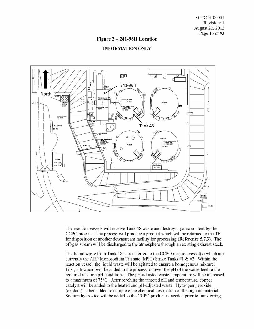
The CCPO process will be installed in Building 241-96H which is located in the H-Area Tank Farm (HTF) adjacent to Tank 48 in the East Hill area. See Figure 2.
The South section of the building presently contains shielded process cells that house the ARP (Reference 5.7.4). The North section of the building housed abandoned ITP equipment; Filtrate Hold Tanks, Benzene Stripper Column and miscellaneous piping and equipment that was removed under the Building 241-96H Demolition and Removal (D&R) Project (Reference 5.7.5).
The CCPO process will be located in the south section of Building 241-96H (presently the Filter Cells that house the ARP process). Support systems, services and utilities will be modified to support the operation of the CCPO process in Building 241-96H. The CCPO process will consist of the following systems (Reference 5.7.1):
• Tank 48 WTS• Reaction Process & Vessels

G-TC-H-00051Revision: 1
August 22, 2012Page 15 of 93
• Bulk Chemical Storage & Delivery System• Ventilation & Purge System• Process Monitor/Control System
The process off-gas equipment is connected to the existing 241-96H South Stack.
The existing infrastructure and utilities will be utilized as much as practical to support the process demands. Existing systems such as Distributed Control System (DCS), instrument air, process water, and electrical distribution will be modified as needed. New support systems will be designed and installed as follows:
Bulk Chemical Storage & Delivery System (to include)• Acid Addition System• Catalyst Addition System• Hydrogen Peroxide Addition System• Caustic Addition System• Antifoam Addition System
The primary point of control for the DCS will be the 3H Control Room. However, local control is provided for testing and maintenance by an existing DeltaV Maintenance Workstation in Building 241-96H.
All equipment that will require maintenance will be positioned to allow for normal maintenance practices applying As Low as Reasonably Achievable (ALARA) principles.
G-TC-H-00051Revision: 1
August 22, 2012Page 16 of 93
Figure 2 – 241-96H Location
INFORMATION ONLY
The reaction vessels will receive Tank 48 waste and destroy organic content by the CCPO process. The process will produce a product which will be returned to the TF for disposition or another downstream facility for processing (Reference 5.7.3). The off-gas stream will be discharged to the atmosphere through an existing exhaust stack.
The liquid waste from Tank 48 is transferred to the CCPO reaction vessel(s) which are currently the ARP Monosodium Titanate (MST) Strike Tanks #1 & #2. Within the reaction vessel, the liquid waste will be agitated to ensure a homogenous mixture. First, nitric acid will be added to the process to lower the pH of the waste feed to the required reaction pH conditions. The pH-adjusted waste temperature will be increased to a maximum of 75°C. After reaching the targeted pH and temperature, copper catalyst will be added to the heated and pH-adjusted waste. Hydrogen peroxide (oxidant) is then added to complete the chemical destruction of the organic material. Sodium hydroxide will be added to the CCPO product as needed prior to transferring
North
241-96H
Tank 48
G-TC-H-00051Revision: 1
August 22, 2012Page 17 of 93
to a receipt tank or a downstream processing facility. As needed, the CCPO product will be cooled down to meet temperature requirements prior to transfer.
Utilities System Tie-ins1.2.1.3
Electrical Power
The primary Motor Control Center (MCC) in Building 241- 96H is MCC-FA, (Reference 5.6.1).
Electrical power for Building 241-96H is obtained from two feeds: “Normal Feed” and “Alternate Feed”. The “Normal Feed” is from Outdoor Substation Transformer ELNA-XFMR-51C and SWGR-51C, cubicle 3B, (Reference 5.6.2). The “Normal Feed” for MCC-FA is parallel with the “Alternate Feed” for MCC-D in the 241-82H building, (Reference 5.6.3).
The “Alternate Feed” for MCC-FA comes from 2500KVA Transformer, ELNA-XFMR-51A and SWGR-51A, cubicle 3B. The “Alternate Feed” for MCC-FA is parallel with the “Normal Feed” for MCC-D, (References 5.6.3, 5.6.4). References 5.6.1 through 5.6.17 are the major electrical drawings for building 241-96H.
The CCPO process is temperature dependent and the temperature must be controlled to provide high efficiency of TPB solids destruction. The existing electrical supply to Building 241-96H must be evaluated to verify it can accommodate the additional electrical power demand for heating of the CCPO reaction vessels.
Domestic Water
Domestic Water (DW) will be provided to CCPO process from the TF, via line DW-252A-P1 at valve DW-V-60 (Reference 5.6.18). The existing DW supply to Building 241-96H (Reference 5.6.19) will require modifications due to the addition of the Bulk Chemical Storage and Delivery System.
Process Water
Process Water for the CCPO process will be supplied from the DW system through the existing Break Tank. (References 5.6.20, 5.6.21, 5.6.22, 5.6.23, 5.6.24)
Inhibited Water
The Inhibited Water (IW) system shall be modified to allow flushing of transfer piping and CCPO components.
Scope:
• Design and install tie-in connections and piping between the existing HTF-East Hill IW system to the CCPO process.

G-TC-H-00051Revision: 1
August 22, 2012Page 18 of 93
Instrument/Plant Air
Plant Air/Instrument Air (80-110 psig) will be provided to the CCPO process by existing lines between the compressor and 241-96H (via line IA-L-202A at valve IA-V-743). These lines are supplied from the East Compressor house from two 200 Hp, 675 actual cubic feet per minute (ACFM) compressors (References 5.6.25, 5.6.26, 5.6.27). Addition of the Bulk Chemical Storage and Delivery system may require modifications to the Plant Air/Instrument Air supply to Building 241-96H.
Steam
Steam will be provided to the CCPO process from the TF, via line MS-L-301A at valve MS-V-757 (Reference 5.6.28). It will continue to be used as the heat source in the personnel areas and as building freeze protection. If no additional demands are placed on the system, the steam supply to Building 241-96H is sufficient as designed and no modifications will be required to this system. If steam is required for the CCPO process in order to meet reaction temperatures requirements, an evaluation will be required to determine if system can supply the additional demands.
Chilled Water
Chilled water will be supplied from the closed-loop chiller installed to service the ARP vessels in 241-96H Process Cells #1 & #2 (References 5.6.29, 5.6.30, 5.6.31).
Support Systems1.2.1.4
Heating, Ventilation & Air Conditioning (HVAC) System
The CCPO process requires two forms of HVAC:
• Building 241-96H HVAC• Process Vessel Ventilation (PVV)
Building 241-96H HVAC
The Building 241-96H HVAC provides ventilation to personnel areas as well as the process cells. The Building 241-96H HVAC provides two functions. The primary function is to circulate the building air through the inlet High Efficiency Particulate Air (HEPA) filters, through the process cells, through the outlet HEPA filters and back into the atmosphere. The second function is to provide fresh air to the personnel areas, as well as heating this air in the winter for personnel comfort and for building freeze protection.
The existing HVAC system has been evaluated for use in the ARP process and determined to be adequate (Reference 5.7.6). Modifications may be required to this system to accommodate the CCPO process due to the possible installation of the Bulk Chemical Storage & Delivery system inside the 241-96H building.

G-TC-H-00051Revision: 1
August 22, 2012Page 19 of 93
PVV
Process vessels are provided with continuous negative ventilation to remove flammable vapors and assist in minimizing contamination (Reference 5.6.32, 5.7.8). The PVV system has been designated as Safety Significant (SS) per the Preliminary Consolidated Hazard Analysis (PCHA) (Reference: 5.7.35). A backfit analysis(Reference: 5.3.3) will need to be performed to evaluate and determine the design modifications and/or compensating measures needed to comply with the new/revised requirements being imposed (i.e., SS classification vs. Production Support (PS)).
Bulk Chemical Storage and Delivery Systems
A Bulk Chemical Storage and Delivery System is necessary to supply nitric acid, copper catalyst, hydrogen peroxide, antifoam, and sodium hydroxide. These systems are expected to require two functional parts: a storage and a feed system. The systems shall provide the necessary components to receive and unload additives near 241-96H, and deliver the additives to the associated feed system. The feed systems shall receive the material from the storage system and shall meter the material into the process.
Scope:
• Design and install a Bulk Chemical and Delivery System to deliver nitric acid, copper catalyst, hydrogen peroxide, antifoam, and sodium hydroxide to the CCPO process. An evaluation will be performed to determine if sodium hydroxide needs to be added in the CCPO process prior to transferring to the TFor downstream facility.
Fire Protection
The ARP Fire Hazard Analysis (FHA) (Reference 5.7.7) concluded the fire hazards potential of the facility was not increased beyond the original design constraints due to the installed fire protection features (sprinkler protection, limited detection and construction features) and the type of operation of the ARP process. A FHA will be developed to determine if any fire systems modifications will be needed due to the CCPO process.
DCS System
Primary control of Building 241-96H CCPO process will be from the 3H Control
Room. Temporary process control from the 241-96H building is available through use
of an existing maintenance work station (Professional station). If receiving facility is
not controlled by the 3H Control Room, both receiving and sending facility Control
Rooms will have the ability to manually stop or initiate the shutdown of the transfer
pump(s) connected to the transfer flow path, either directly or by interlock or by
removal of the appropriate DCS permissive to the sending facility.

G-TC-H-00051Revision: 1
August 22, 2012Page 20 of 93
Waste Transfer System1.2.1.5
Waste transfer paths shall be established as follows:
• Tank 48 to Building 241-96H reaction vessel(s)• Building 241-96H reaction vessel(s) to the TF Receipt Tank or downstream
processing facility
Conceptual transfer line arrangements are shown in Attachment 1 and Attachment 2. The intent is to use as much of the existing infrastructure as feasible.
Transfer from Tank 48 to Building 241-96H Reaction Vessel(s)
Independent and dedicated transfer paths and transfer pumps shall be provided to transfer Tank 48 bulk waste to Building 241-96H reaction vessel(s). The system shall be similar to typical TF bulk slurry removal systems, consisting of mixing the waste with (existing) slurry pumps to suspend solids followed by transfer of the slurry with a standard single centrifugal pump.
Scope:
• Use the existing transfer pump systems in Tank 48.• Use the existing transfer line in Tank 48 Riser H and install a new jumper from
Wall Nozzle 16 in the Process Cell #1, connecting the old ITP precipitate supply line from filter feed pump #1 to the reaction vessel in Process Cell#1 Tank Nozzle 14.
• Use the existing transfer line in Tank 48 Riser G and install a new jumper from Wall Nozzle 16 in the Process Cell #2, connecting the old ITP precipitate supply line from filter feed pump #2 to the reaction vessel in Process Cell#2 Tank Nozzle 3.
• The transfer pumps will be controlled by the DeltaV DCS. The DCS must automatically stop the transfer when the target reaction vessel(s) fill volume is achieved.
• An SS hardwired electrical disconnect for the transfer pumps is required.

G-TC-H-00051Revision: 1
August 22, 2012Page 21 of 93
Transfer of Product from Building 241-96H to TF Receipt Tank or Downstream Processing Facility
A transfer path shall be provided from the reaction vessel(s) to the HTF designated receipt tank or downstream processing facility. The CCPO process will utilize the 241-96H valve box located between Tank 48 and 241-96H. This valve box will allow the CCPO process to tie into line 3056 which is a transfer path to H-Area Diversion Box (HDB)-7. Existing transfer lines from Process Cell #1 & #2 to the Building 241-96H Valve Box shall be used to transfer product slurry from the CCPO process to the HTF designated receipt tank or downstream processing facility via HDB-7 (References 5.6.30, 5.6.31, 5.6.33, 5.6.34, 5.6.35).
Scope:
• An SS electrical disconnect switch capable of stopping a transfer from the reaction vessel(s) to the TF receipt tank or downstream facility is required (References 5.7.9)
• Utilize the existing flow path from the reaction vessel(s) to the 241-96H valve box.
• The existing pumps in the reaction vessels must be evaluated to ensure they are suitable for this application. If not, new transfer pumps will be required.
• The transfer pumps will be controlled by the DeltaV DCS. The DCS must automatically stop the transfer when the target reaction vessel(s) transfer volume is achieved.
• Design/modify and install new jumpers in 241-96H valve box in a configuration to meet the following objectives:
• Provide double valve isolation to Tank 49 during transfers from CCPO product slurry transfers from Process Cell #1 & #2 to HDB-7.
• Provide double valve isolation to Building 241-96H valve box during transfers between Tank 49 and HDB-7.
• Provide a flow path from HDB-7 to TF receipt tank or downstream processing facility.
1.2.2 Basis of Modification
Tank 48 is no longer needed to be Returned to Service to support the Life-Cycle Liquid Waste Disposition System (Reference 5.7.12).
A review of the series of options that have been previously considered for the treatment of the Tank 48H TPB solids concluded small-tank chemical destruction and direct vitrification were promising in light of advancements in the liquid waste systems/processes. The chemical destruction option became viable when experimentation using copper-catalyzed peroxide destruction chemistry revealed near complete TPB oxidation in alkaline conditions. In addition, the availability of the stainless steel tanks in the current ARP, contained in 241-96H, may be used as small-tank reactors that will be resistant to corrosion (Reference 5.7.13).

G-TC-H-00051Revision: 1
August 22, 2012Page 22 of 93
1.2.3 Objectives of Modification
The objective of this modification is to design and install a CCPO process in Building 241-96H to support the organic destruction of the Tank 48 contents (Reference 5.7.1).
The CCPO process shall be capable of treating the bulk content of the waste. The current Tank 48 waste inventory is approximately 240,000 gallons.
1.2.4 Plant Modification Location
The TTP modifications can be grouped as follows (as shown previously in Figure 1):
• Building 241-96H Facility• H-Area WTS• H-Area Utility and Support Systems (including control room)
All modifications will be performed in HTF as described in Section 1.2.1.
1.3 Plant Modification Boundaries and Interface Requirements
The following section defines the plant modification boundaries and interface requirements (IR) specific to the activities governed by this TR&C. Interface Control Documents (ICD) will be developed and approved (if required, pending the selection of a final flow sheet) by the respective facilities.
Figure 3 depicts the interfaces of the CCPO process:

G-TC-H-00051Revision: 1
August 22, 2012Page 23 of 93
Nitrogen
IR.11.0
HVAC
IR.9.0
Building
241-96H
IR.1.0
Domestic Water
IR.3.0
Inhibited
Water
IR.5.0
Electrical
PowerIR.2.0
Chilled Water
IR.8.0
ProcessWater
IR.4.0
Fire Protection
IR.12.0
Steam
IR.7.0
IR.15.0
Reaction Vessel(s) Product Transfer
Tank 48
Transfer
IR.14.0
Instrument/Plant Air
IR.6.0
Bulk Chemical Storage & Delivery
IR.10.0
CCPO
Process
DCS
IR.13.0
Figure 3 – 241-96H CCPO Interface Diagram
1.3.1 IR.1.0 Building 241-96H
IR.1.1 The CCPO process will be located in Building 241-96H. Some equipment, such as the Bulk Chemical Storage and Deliver system may need to be located outside the building or in adjacent rooms. ARP MST Strike Tanks #1 and #2 are located in ARP Process Cells #1 and #2 and will be used as the CCPO reaction vessels.
Basis: The CCPO process (in an alkaline environment) is a viable option for the destruction of the Tank 48H TPB solids, due to the future availability of the stainless steel ARP Strike Tanks. (Reference 5.7.1)

G-TC-H-00051Revision: 1
August 22, 2012Page 24 of 93
IR.1.2 Foundations and support structure within Building 241-96H that willsupport new loadings shall be evaluated if any new equipment or systems are installed inside the building.
Basis: Building 241-96H structural limits shall not be exceeded (also see section 1.6).
IR.1.3 Provide the 241-96H floor filtrate hold tank room with a limited-volume, lined, liquid collection and pumping system if Bulk Chemical Storage and Delivery system is installed inside the room.
Basis: A stainless steel floor liner provides a limited-volume liquid containment barrier that isolates liquid spills and water that would be discharged from sprinklers in the event of a fire.
1.3.2 IR.2.0 Electrical Power
IR.2.1 Electrical power shall be provided to the CCPO Bulk Chemical Storage & Delivery system components to meet required demands.
IR.2.2 Electrical power shall be provided to the strike tanks in order to meet high process temperature requirements (i.e., ≥ 35°C) for the CCPO process.
Basis: The CCPO process is temperature dependent and the temperature must be controlled to provide high efficiency of TPB solids destruction.
IR.2.3 Backup power shall be provided for the CCPO process. A feasibility study shall be performed to determine if the existing diesel generator (Reference: 5.6.17) can be refurbished or a new one installed.
1.3.3 IR.3.0 Domestic Water
IR 3.1 DW shall be provided for safety showers and eyewash stations, as required.
Basis: Safety showers and eyewash stations shall be required during operation of the CCPO process at Building 241-96H. (Reference 5.3.1)

G-TC-H-00051Revision: 1
August 22, 2012Page 25 of 93
1.3.4 IR.4.0 Process Water
IR 4.1 Process water shall be provided from the Break Tank (HI-241-96H-PWS-TK-1) to support a maximum instantaneous demand of 50 gpm.
Basis: Process water is required for the following uses:
• Supply for, decontamination and flushing purposes
1.3.5 IR.5.0 Inhibited Water
IR 5.1 IW shall be provided to the CCPO process from the existing HTF-East Hill IW system.
Basis: IW is needed for flushing of transfer piping and CCPO components.
1.3.6 IR.6.0 Instrument/Plant Air
IR 6.1 Instrument/Plant Air shall be provided from the TF compressed air system at a nominal 90/160 psig to meet a demand of TBD Standard Cubic Feet per Minute (SCFM).
Basis: The existing Instrument Air supply system may not support continuous operation of the CCPO process.
1.3.7 IR.7.0 Steam
IR 7.1 Steam shall be provided at 150 psig from the site steam supply system piping outside of 241-96H.
Basis: Steam may be required for the CCPO chemical reaction temperature requirements. The estimated pressure and continuous demand is based on process requirements.
1.3.8 IR.8.0 Chilled Water System
IR 8.1 The existing Chilled Water System shall be used to control the reaction vessel temperature.

G-TC-H-00051Revision: 1
August 22, 2012Page 26 of 93
Basis: The CCPO process is temperature dependent and the temperature must be controlled to provide high efficiency of TPB solids destruction.
1.3.9 IR.9.0 HVAC
IR.9.1 The HVAC design shall have three confinement ventilation zones. The Primary Confinement Zone or PVV consists of the process tanks, vessels HEPA filters, blowers, and interconnecting piping. This zone conveys process off-gases to the 241-96H South stack for discharge to the atmosphere via HEPA filtration. The Secondary Confinement Zone consists of process cells #1 & #2, HEPA filters, blowers, and interconnecting piping. The Tertiary Confinement Zone is the existing building ventilation system. This existing system acts as the final barrier to prevent the release of airborne hazardous and radioactive particulate material to the environment and maintains building temperature within personnel habitability comfort levels. The design shall consider using as much of the existing system as practical. The design shall provide an integrated system such that all three zones discharge through the existing South stack. (Reference 5.7.14)
Basis: The CCPO Process generates off-gas, heat and potentially contains radioactive particles that must be removed prior to discharge to the atmosphere. (Reference 5.7.1)
IR.9.2 The reaction vessels PVV System must be evaluated to validate itssuitability for this application. A backfit analysis is required due to the functional classification of the ventilation system as SS in the PCHA.
Basis: The CCPO process material and frequency of operation is different than the current design basis for these systems. As a result, the existing ventilation must be evaluated to ensure it is suitable for the CCPO process strategy and still comply with standard and safety related requirements.
IR.9.3 The Bulk Chemical Storage and Delivery System vessels must be evaluated for chemical fumes containment (which could require a vacuum on the vessel) based on the location of the system. If the system is placed within the confines of 241-96H modifications are anticipated.
Basis: The Bulk Chemical Storage and Delivery System Vessels will contain a strong acid base, and oxidant which will emit fumes.
1.3.10 IR.10.0 Bulk Chemical Storage and Delivery
IR.10.1 Provide a 50 wt.% (10.35 M) nitric acid addition system for the CCPO process. The system shall include a 1600-gallon capacity storage and feed system for the nitric acid (Reference: 5.7.37). The storage system

G-TC-H-00051Revision: 1
August 22, 2012Page 27 of 93
shall provide the components necessary for receipt, and off-loading of nitric acid near or in 241-96H. The feed system shall provide the means for the nitric acid to be received from the storage system and the metering of the nitric acid at a flow rate of 4.2 gpm (Reference: 5.7.37)into the process.
IR.10.2 Provide a copper catalyst addition system (copper nitrate) for the CCPO process. The system shall include a 10-gallon capacity storage and feed system for the catalyst (Reference: 5.7.37). The storage system shall provide the components necessary for receipt, and off-loading of catalystnear or in 241-96H. The feed system shall provide the means for the catalyst to be received from the storage system and the metering of catalyst into the process.
IR.10.3 Provide a 50 wt.% (17.6 M) hydrogen peroxide addition system for the CCPO process. The system shall include a 4000-gallon capacity storage and feed system for the hydrogen peroxide (Reference: 5.7.37). The storage system shall provide the components necessary for receipt, and off-loading of hydrogen peroxide near or in 241-96H. The feed system shall provide the means for the hydrogen peroxide to be received from the storage system and the metering of the hydrogen peroxide at a flow rate of 0.02 gpm (1.2 gal/hr) into the process (Reference: 5.7.37).
IR.10.4 Provide an antifoam addition system for the CCPO process. The system shall include storage and feed system for the antifoam. The storage system shall provide the components necessary for receipt, and off-loading of antifoam near or in 241-96H. The feed system shall provide the means for the antifoam to be received from the storage system and the metering of the antifoam at a flow rate of TBD into the process.
IR.10.5 Provide a sodium hydroxide addition system for the CCPO process. An evaluation will be performed to determine if sodium hydroxide needs to be added in the CCPO process prior to transferring to the TF or downstream facility. The system shall include a 1000-gallon capacity storage and feed system for the sodium hydroxide (Reference: 5.7.37). The storage system shall provide the components necessary for receipt,and off-loading of sodium hydroxide near or in 241-96H. The feed system shall provide the means for the sodium hydroxide to be received from the storage system and the metering of the sodium hydroxide at a flow rate of TBD into the process.
IR.10.6 Provide leak containment for the chemicals as required ensuring that incompatible chemicals will not be mixed (Reference: 5.7.35). Refer toSection 3.1.2.

G-TC-H-00051Revision: 1
August 22, 2012Page 28 of 93
1.3.11 IR.11.0 Fire Protection
IR.11.1 Fire protection systems shall meet the requirements of Section 3.2.2.8, Fire Protection, which requires compliance with National Fire Protection Association (NFPA) and Department of Energy (DOE) Fire Protection codes and standards and also requires adherence to the SRS Fire Protection Design Criteria.
Note: The 241-96H Fire Alarm Panel communication connects Building 241-96H and the SRS Central Fire Station. (Reference 5.6.36)
1.3.12 IR.12.0 DCS
IR.12.1 The existing ARP Emerson DeltaV DCS shall be modified to monitor and control the 241-96H CCPO process. The DCS shall be designed as an extension of the Liquid Waste Control Network (LWCN) DeltaV DCS to permit control and monitoring from the 3H Control Room. In addition, the existing Maintenance Workstation shall be modified to support startup and maintenance from within Building 241-96H as required.
Basis: Reference 5.7.16
IR.12.2 A DeltaV DCS interface with the variable frequency drive (VFD) shall be provided to monitor and control the Tank 48 H & G Risers Transfer Pumps. Control and monitoring shall be from the 3H Control Room via the existing LWCN DeltaV DCS.
Basis: Reference 5.7.16
IR.12.3 Installed radiation monitoring equipment (RME) shall be tied-in to the DCS.
Basis: Installed RME may be required for the CCPO process.
1.3.13 IR.13.0 Transfer of Bulk Waste to 241-96H Reaction Vessels
IR 13.1 A transfer path and transfer pump shall be configured such that bulk waste feed from Tank 48 Riser H can be transferred to the Building 241-96H reaction vessel #1 Inlet located in Process Cell #1. The transfer pump shall be controlled by the DeltaV DCS. The DCS must automatically stop the transfer when the target reaction vessel fill volume is achieved. An SS hardwired electrical disconnect for the Tank 48 H Riser transfer pump is required. The existing transfer line from Tank 48

G-TC-H-00051Revision: 1
August 22, 2012Page 29 of 93
H riser will be used. A new jumper from Wall Nozzle 16 in the Process Cell #1 is needed, connecting the old ITP precipitate supply line to the reaction vessel Tank Nozzle 14.
IR 13.2 A transfer path and transfer pump shall be configured such that bulk waste feed from Tank 48 Riser G can be transferred to the Building 241-96H reaction vessel #2 Inlet located in Process Cell #2. The transfer pump shall be controlled by the DeltaV DCS. The DCS must automatically stop the transfer when the target reaction vessel fill volume is achieved. An SS hardwired electrical disconnect for the Tank 48 G Riser transfer pump is required. The existing transfer line from Tank 48 G riser will be used. A new jumper from Wall Nozzle 16 in the Process Cell #2 is needed, connecting the old ITP precipitate supply line to the reaction vessel Tank Nozzle 3.
Basis: The CCPO process is designed only to process Tank 48 waste and a method of delivering Tank 48 bulk waste to the CCPO process must be installed (References 5.7.15).
1.3.14 IR.14.0 Reaction Vessel(s) Product Transfer
IR.14.1 A transfer path shall connect the reaction vessel(s) and the HTF designated receipt tank or downstream facility via 241-96H valve box/HDB-7 such that slurry from the reaction vessel(s) can be transferred for further processing (Reference 5.7.3). The reaction vessels have existing pumps installed and may be used to meet the objective of this IR. However, a design evaluation will be required to establish its acceptability.
Basis: Process strategy is to transfer the product slurry to a receipt tank or downstream facility.
IR.14.2 The temperature of the transferred slurry shall not exceed 40°C. Anengineering evaluation will be required to establish acceptability.
Basis: The product slurry must meet the temperature requirements limits of the Corrosion Control Program and Technical Safety Requirements (TSRs) of the TF and downstream processing facilities, (References 5.7.10, 5.7.11).

G-TC-H-00051Revision: 1
August 22, 2012Page 30 of 93
1.4 Modification Classifications
1.4.1 Functional Classification
Where applicable, Systems, Structures, and Components (SSCs) located outside of 241-96H will have a functional classification consistent with similar SSCs in the existing CSTF Safety Basis documentation (Reference 5.7.9). Therefore, transfer lines and jackets located outside of 241-96H will be classified as SC/SS. The transfer pumps (Tank 48 H & G Risers Transfer Pumps and reaction vessel Transfer Pumps only) manual disconnect device is functionally classed as SS. Waste tank riser plugs and port plugs are functionally classed SS for airborne confinement. Materials and fabrication for riser plugs and port plugs are functionally classed PS. Commodities passing through a riser plug or port plug shall be functionally classed per their function. Refer to Reference 5.7.9 for additional clarification of riser plugs. Therefore, the highest functional classification for this plant modification is Safety Class (SC).
The PCHA (Reference 5.7.35) determined that the highest functional classification for components related to the CCPO process to be SS (PVV, process cell ventilation, process cells, reaction vessels, diesel generator, CLFL monitoring, reaction vessel temperature monitoring with alarm and interlock, process cell conductivity probes with alarm).
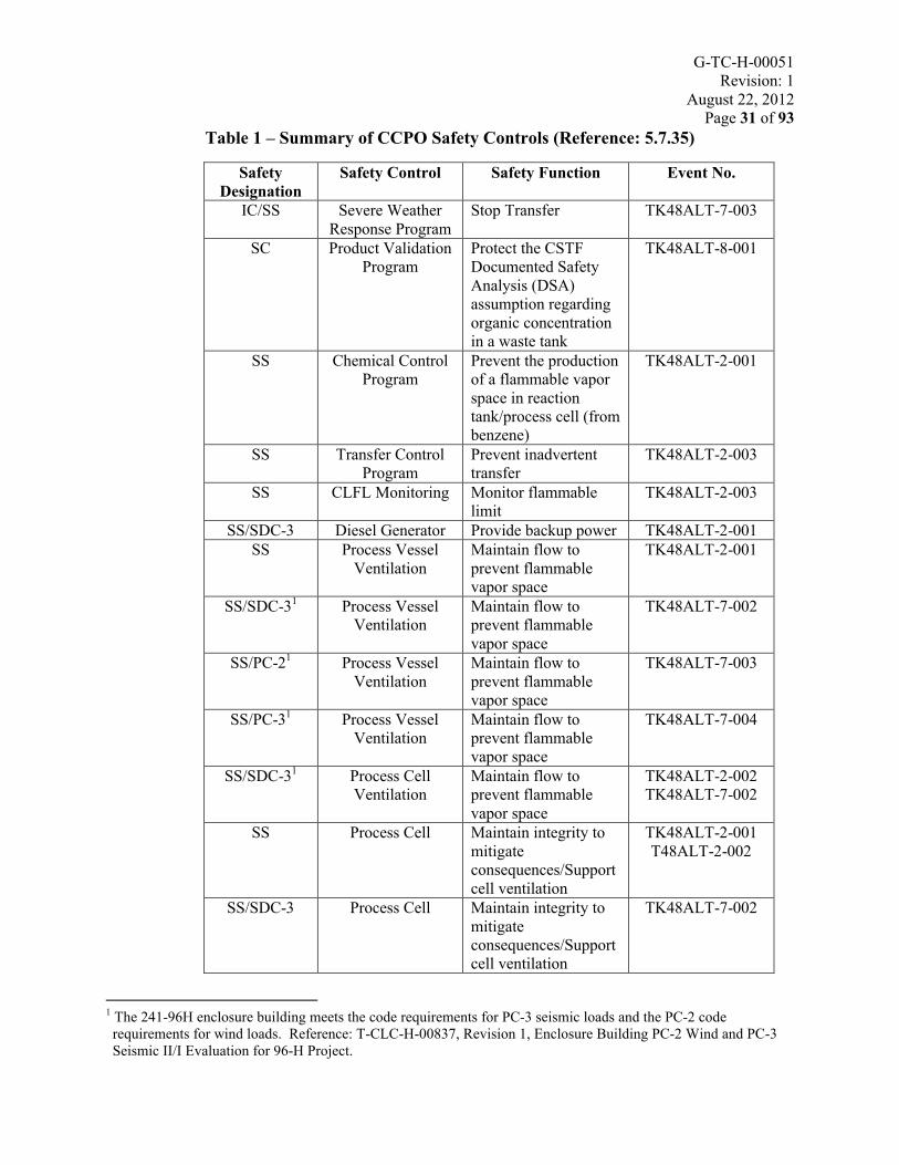
Table 1 provides a summary of safety controls and the respective safety designation perthe PCHA.
G-TC-H-00051Revision: 1
August 22, 2012Page 31 of 93
Table 1 – Summary of CCPO Safety Controls (Reference: 5.7.35)
Safety Designation
Safety Control Safety Function Event No.
IC/SS Severe Weather Response Program
Stop Transfer TK48ALT-7-003
SC Product Validation Program
Protect the CSTF Documented Safety Analysis (DSA)assumption regarding organic concentration in a waste tank
TK48ALT-8-001
SS Chemical Control Program
Prevent the production of a flammable vapor space in reaction tank/process cell (from benzene)
TK48ALT-2-001
SS Transfer Control Program
Prevent inadvertent transfer
TK48ALT-2-003
SS CLFL Monitoring Monitor flammable limit
TK48ALT-2-003
SS/SDC-3 Diesel Generator Provide backup power TK48ALT-2-001SS Process Vessel
VentilationMaintain flow to prevent flammable vapor space
TK48ALT-2-001
SS/SDC-31 Process Vessel Ventilation
Maintain flow to prevent flammable vapor space
TK48ALT-7-002
SS/PC-21 Process Vessel Ventilation
Maintain flow to prevent flammable vapor space
TK48ALT-7-003
SS/PC-31 Process Vessel Ventilation
Maintain flow to prevent flammable vapor space
TK48ALT-7-004
SS/SDC-31 Process Cell Ventilation
Maintain flow to prevent flammable vapor space
TK48ALT-2-002TK48ALT-7-002
SS Process Cell Maintain integrity to mitigate consequences/Support cell ventilation
TK48ALT-2-001T48ALT-2-002
SS/SDC-3 Process Cell Maintain integrity to mitigate consequences/Support cell ventilation
TK48ALT-7-002
1 The 241-96H enclosure building meets the code requirements for PC-3 seismic loads and the PC-2 code requirements for wind loads. Reference: T-CLC-H-00837, Revision 1, Enclosure Building PC-2 Wind and PC-3 Seismic II/I Evaluation for 96-H Project.

G-TC-H-00051Revision: 1
August 22, 2012Page 32 of 93
Safety Designation
Safety Control Safety Function Event No.
SS/PC-2 Process Cell Maintain integrity to mitigate consequences
TK48ALT-7-003
SS/PC-3 Process Cell Maintain integrity to mitigate consequences
TK48ALT-7-004
SS Process Vessel Maintain integrity to prevent release
TK48ALT-2-002
SS/SDC-3 Process Vessel Maintain integrity to prevent release
TK48ALT-7-002
SS Temperature Monitoring with
Alarm and Interlock
Maintain temperature below analyzed limits
TK48ALT-2-001
SS Cell Conductivity Probes with Alarm
Detect leak in process cell
TK48ALT-2-002
SS Tank 48 Ventilation
Maintain flow to prevent flammable vapor space
TK48ALT-2-003
FC Process Vessel Maintain integrity to prevent release
TK48ALT-1-002TK48ALT-3-002
FC Process Cell Leak Detection
Notify personnel of material in sump of process cell
TK48ALT-1-002
FC Combustible loading Program
Limit combustible material inside process cell to prevent release
TK48ALT-1-002
FC Process Cell Sump With Conductivity
Probe
Contain release of material in the process cell to mitigate consequences
TK48ALT-3-001TK48ALT-3-002
FC Tank Level Indication
With Interlock
Stop addition of material into reaction vessel
TK48ALT-2-002TK48ALT-3-001
FC Temperature Monitoring
Maintain temperature below analyzed limits to prevent overheating
TK48ALT-3-003
FC Chilled Water System
Control temperature to prevent overheating
TK48ALT-3-003
FC Radiological Protection Program
Protect the worker during maintenance while shielding is removed
TK48ALT-4-001

G-TC-H-00051Revision: 1
August 22, 2012Page 33 of 93
1.4.2 Hazard Classification
The hazard classification for this facility is Hazard Category 2, Non-reactor Nuclear Facility. (Reference 5.1.3.1)
1.4.3 Performance Category
The Natural Phenomena Hazard (NPH) Performance Categories for the SSCs affected by this modification are determined as part of the PCHA development effort and documented in Table 1. (Reference: 5.7.35)
1.4.4 Facility Controls
The PCHA identifies facility controls (FC) for the safety of collocated and facility workers, and for programmatic reasons such as to limit loss of production or facility damage. Administrative FC requirements are outside the scope of TR&C documents.
1.5 Technical Issues and Assumptions
1.5.1 Issues
A strategy to validate CCPO process organic destruction requirements must be 1.5.1.1developed. Research & Development (R&D) data includes a measure of residual organics in the product within the minimum detection level of analytical equipment; however, a means to correlate this data to the organic destruction requirement of the receipt tank or the downstream processing facility must be developed.
A strategy to disposition suspect organic CCPO process material in the event of a 1.5.1.2process upset must be developed. Suspect organic material could be in the form of product slurry after reaction, or material leaked into process cells #1 & #2 sumps from a waste feed line leak.
The PCHA requires diesel back up power for the CCPO PVV system. A 1.5.1.3determination of how soon PVV must be restored due to loss of power must be performed to ensure benzene LFL is maintainesd within safety limits.
1.5.2 Assumptions
Treating 390,000 gallons of Tank 48 waste (240,000 gallons current inventory plus 1.5.2.1150,000 of liquid to maintain slurry pump operation) in four years will achieve a remaining tank inventory that will allow heel disposition and tank closure.
The existing 241-96H MCCs will be available to supply required CCPO Loads.1.5.2.2

G-TC-H-00051Revision: 1
August 22, 2012Page 34 of 93
The existing utilities and infrastructure (Instrument Air/Plant Air, water, steam, and 1.5.2.3electrical power) will be available to deliver the needs of the CCPO process.
The CCPO process will provide slurry product to the Receipt Tank or downstream 1.5.2.4processing facility.
The CCPO Process will be monitored and controlled from the 3H Control Room 1.5.2.5(Building 241-2H) via the existing LWCN DCS. The LWCN DCS has adequate capacity to handle the additional controller(s) and I/O associated with the CCPO Process.
The 3H control room has adequate space and utilities to handle the additional control 1.5.2.6equipment and personnel.
It is anticipated that one dedicated Control Room Operator (CRO) and a minimum of 1.5.2.7one dedicated Surveillance Operator (SO) will be required for operations (valving operations, chemical additions, maintenance activities, startup and shutdown). An Operator task Analysis will determine actual Operator requirements.
The existing Tank 48 slurry pumps and other equipment will be available to mix the 1.5.2.8bulk contents of Tank 48.
Verified - The existing slurry pumps are available and described as active equipment in the Tank 48 Safety Basis, Reference 5.7.9 Chapter 18.
Modifications to Tank 48 slurry pumps are not required.1.5.2.9
The existing 241-96H lab facility on east side of the former stripper area (including 1.5.2.10ventilation hoods, shielded sample storage, lab sinks, etc.) will be available. The HVAC equipment for the 241-96H lab facility was removed during the 241-96H D&R Project.
The ARP MST Strike Tanks #1 and #2 will be available for use as the CCPO reaction 1.5.2.11vessels.
The existing Process Information (PI) System has adequate capacity for storage of 1.5.2.12CCPO process data.
Existing transfer paths will be available to transfer the contents of reaction vessels #1 1.5.2.13& #2 to the HTF designated receipt tank or downstream processing facility.
There is only one transfer path available from the Strike Tank in Process Cell #1 to any proposed receipt tank in the HTF. Specifically, the transfer path is Line 705A at Nozzle 17 (Drawing M-M6-H-8213 and -8212; Line 705A) to HDB-7 (Drawing M-M6-H-8297) by way of the 241-96H Valve Box (See Drawing M-M6-H-2395). The jumpers and valve arrangements in HDB-7 can be configured such that any tank in HTF can be reached.

G-TC-H-00051Revision: 1
August 22, 2012Page 35 of 93
There is only one transfer path available from the Strike Tank in Process Cell #2 to any proposed receipt tank in the HTF. Specifically, the transfer path is Line 1105A at Nozzle 17 (Drawing M-M6-H-8214 and -8212; Line 1105A) to HDB-7 (Drawing M-M6-H-8297) by way of the 241-96H Valve Box (See Drawing M-M6-H-2395). The jumpers and valve arrangements in HDB-7 can be configured such that any tank in HTF can be reached.
The existing interior finishes and coatings in 241-96H meet NFPA 801 requirements 1.5.2.14and limitations for flame spread and smoke developed rating (References 5.2.1).
The Tank 48 transfer pumps design criteria assumes that the minimum Tank 48 waste 1.5.2.15level is no less than 26 inches to support slurry pump operation during Tank 48 to 241-96H transfers. Slurry pump operation is limited by the DSA to minimize the potential for pump discharge “rooster tailing” and possibly aerosolizing the tank’s waste.
The transfers from the reaction vessels to the receipt tank or downstream processing 1.5.2.16facilities will be categorized as "waste transfers" per the CSTF Transfer Control Program.
Lower flammability limit (LFL) controls will be used to maintain the CCPO reaction 1.5.2.17vessel(s) vapor space within flammability requirements.
1.6 Applicable Studies
1.6.1 Plant & Instrument Air Study – An evaluation of the existing system capacity shall be performed. The existing capacity may be inadequate to supply the demand for the Bulk Chemical Storage and Delivery system.
1.6.2 Electrical Load Study - An evaluation of the existing system capacity including substation availability and detailed load study shall be performed. The existing power feed from 241-96H MCCs may be inadequate and require upgrades, or a new feed shall be required.
1.6.3 Compressor Lube Oil Program Evaluation - All equipment and components which require lubrication fluids and have the potential to introduce flammable vapors into process areas downstream of the organic treatment process shall be evaluated to ensure their contribution does not exceed 5% of the composite lower flammability limit (CLFL)as required by Reference 5.7.9.
1.6.4 The existing chilled water system capacity, reaction vessel(s) agitators, pumps, and ventilation systems shall be evaluated for this application.
1.6.5 ARP Strike Tanks backfit analysis – A backfit analysis is required due to the functional classification of the reaction vessels as SS in the PCHA.
1.6.6 PVV system backfit analysis – A backfit analysis is required due to the functional classification of the PVV system as SS in the PCHA.
1.6.7 A study to determine if the South exhaust stack materials of construction (carbon steel) are compatible with gases released during CCPO process operation.

G-TC-H-00051Revision: 1
August 22, 2012Page 36 of 93
1.6.8 A study shall be performed to determine if the existing South stack height (and possibly the north stack) at 241-96H is sufficient to protect personnel from effluents released during the CCPO process.
1.6.9 Ventilation shall be evaluated against NFPA 69 criteria for ventilated locations (see Design Constraint (DC) 3.2.2.8.1).
1.6.10 Evaluate the need to provide chemical fume containment for the Bulk Chemical Storage and Delivery System vessels.
1.6.11 The existing transfer pump in Tank 48 riser H must be evaluated to determine if it is stillfunctional and can be used to transfer Tank 48 slurried contents to the Process Cell #1 reaction vessel. This pump has not been operated in ~ 17 years and the inlet is ~9 inches off the bottom. COMPLETE - Existing transfer pump was evaluated for use. (Reference 5.7.23)
1.6.12 The existing transfer pump in Tank 48 riser G must be evaluated to determine if it is still functional and can be used to transfer Tank 48 slurried contents to the Process Cell #2 reaction vessel.
1.6.13 Perform a Potential Impact Category (PIC) level determination for stack monitoring in accordance with Manual 3Q, ECM 4.15.
1.6.14 A Human Factors Engineering (HFE) review shall be performed using the tools provided by Reference 5.2.2.
1.6.15 A hazard evaluation must be performed for nitric acid, copper catalyst, sodium hydroxide, antifoam, and hydrogen peroxide and documented in the PCHA.
1.6.16 Designation of Building 241-96H grated areas as mezzanines, equipment platforms, or floors with open grating is required. Different International Building Code (IBC) limitations will apply, depending on the designation (see DC.3.2.1.1).
1.6.17 Evaluate if the existing ARP MST Strike Tanks are acceptable for use in the CCPO process.
1.6.18 Perform an FHA.
1.6.19 Perform an evaluation to determine handling of non-conforming CCPO process material (e.g., potential feed overflows).
1.6.20 Determine the total absorbed radiation dose rate for the design life of the CCPO process.
1.6.21 Evaluate the existing shielding (basis of 1.1 Ci Cs-137/gal) on the proposed feed to the CCPO process. Process Cell #1 & #2 ventilation inlet ducts suspect for higher curie loading. (Reference 5.7.33)
1.6.22 Determine temperature limit for CCPO product transfer into receipt tank or downstream processing facility.

G-TC-H-00051Revision: 1
August 22, 2012Page 37 of 93
1.6.23 Perform an evaluation to determine if sodium hydroxide needs to be added in the CCPO process prior to transferring to the TF or downstream facility.
1.6.24 Copper nitrate is a solid. Evaluate preparation of solution in-house versus pre- made purchased solutions for processing use.
1.6.25 Perform an Operator Task Analysis to determine Operator requirements.
1.6.26 Facility chemical inventory for the CCPO process will be assessed per the requirements of the Consolidated Hazard Analysis Process (CHAP) Program and Methods Manual SCD-11 (Reference 5.7.35). A Preliminary Emergency Planning Hazards Assessment (EPHA) needs to be completed.
1.6.27 Existing steel egress doors may not comply with NFPA 101 for fire rating or maximum force to open when confinement ventilation system modifications described herein are implemented. As a result the doors may need to be replaced or equivalencies/exemptions written and approved by DOE.
1.6.28 Perform a backfit/cost analysis on the existing diesel generator to meet SS requirements(Reference: 5.6.17).
1.6.29 Perform a mixing/model study of the reaction vessels agitators (Reference: 5.7.1).
1.6.30 Perform an evaluation to determine if the current steam system can handle CCPO demands due to reaction temperature requirements.
1.6.31 Perform a backfit/cost analysis on the existing Reaction Vessel Temperature Monitoring with Alarm & Interlock to meet SS requirements (Reference: 5.7.35)
1.6.32 Evaluate use of reaction vessels cooling coils as a heating system for the process (Reference: 5.7.1).
1.6.33 Evaluate the need to determine the effects of the Tank 48 cooling coils on mixing of the tank contents (Reference: 5.7.1).
1.6.34 Perform a backfit/cost analysis on the existing cell conductivity probes with alarm to meet SS requirements (Reference: 5.7.35)
1.6.35 Reevaluate the current Tank 48 DSA requirement for aerosolization from rooster tailing for possible removal of the requirement.
FUNCTIONS AND PERFORMANCE REQUIREMENTS2.
This section provides functions and performance requirements (PR) and the bases for each requirement. Functions are identified by an “F” before the number. Performance Requirements are identified by a “PR” before the number.

G-TC-H-00051Revision: 1
August 22, 2012Page 38 of 93
2.1 Upper Level Functions
The upper level HLW System functions are as follows:
Figure 4 – Upper HLW System Functions
HLWD
DDDDDDDD
DD DDDD
Manage HLW
Receive Waste Store Waste Process WasteDisposition
Waste
Evaporate Waste
Cesium Removal
Actinide Removal

G-TC-H-00051Revision: 1
August 22, 2012Page 39 of 93
2.2 Plant Modification Functions and Performance Requirements
Tank 48H currently holds radioactive legacy liquid waste material from the operation of the ITP process. The tank contains organic TPB compounds, predominantly insoluble potassium tetraphenylborate (KTPB) along with smaller quantities of cesium tetraphenylborate (CsTPB). The TPB has the potential to decompose to benzene (C6H6), which necessitates the use of controls to maintain the concentrations of flammable components in the Tank 48H vapor space sufficiently below the CLFL. As a result, the chemistry of the Tank 48H material poses a significant challenge to the salt processing and sludge processing facilities within the liquid waste system. Therefore, destruction of the organics prior to permanent disposition is a key element for the liquid waste life-cycle completion.
The primary Function of 241-96H CCPO is to destroy organics in Tank 48 waste. The CCPO upper level functions are as follows:
Figure 5 - Upper Level CCPO Functional Hierarchy Diagram2
Transfer WasteFrom Tank 48 Control Process
DestroyOrganics
Treat Waste1
Monitor Process
F.1.0
F.1.4F.1.3F.1.2F.1.1 F.1.5Transfer Product
2
This functional area also includes addition of acid, caustic, catalyst, and antifoam.

G-TC-H-00051Revision: 1
August 22, 2012Page 40 of 93
Figure 6 – Upper Level CCPO Functional Flow Block Diagram3
Transfer WasteFrom Tank 48
Treat Waste1
Transfer Product
Monitor Process
Control Process
F.1.1
F.1.4
F.1.2
F.1.5
F.1.3
3
This functional area also includes addition of acid, caustic, catalyst, and antifoam.

G-TC-H-00051Revision: 1
August 22, 2012Page 41 of 93
The functions and their classification are allocated to individual SSC(s) as shown in Table 2 below. The following functions and performance requirements shall be met:
Table 2 – CCPO Functions Classification
Function Number
Title Functional Classification
Allocated to SSC3
Performance Requirement
Number
Performance Requirement Basis
F.1.0 Destroy Organics SC 241-96H CCPO Facility
PR1.1 None (Addressed by Sub-Functions below)
F.1.1 Transfer Waste From Tank 48 to Reaction Vessel(s)
PS Tank 48 Transfer Pump
PR1.1.1 The transfer of waste from Tank 48 to the CCPO reaction vessels shall maintain a minimum axial velocity of 3.0 ft/sec.
Maintaining this axial velocity will avoid the settling of sludge or suspended solids in the transfer system. References 5.7.17, 5.7.9section 3.4.1.5.2
F.1.1 Transfer Waste From Tank 48 to Reaction Vessel(s)
PS Tank 48 Slurry Pumps
PR1.1.2 The Tank 48 waste is well mixed prior to the transfer into the reaction vessel.
Maintain inhalation dose potential (IDP)assumption. Reference 5.7.35
F.1.1 Transfer Waste From Tank 48 to Reaction Vessel(s)
PS Tank 48 Transfer Pump
PR.1.1.3 The flow rate from Tank 48 is limited to 360 gpm (for transfer lines in general and consistent with code allowable pressure for transfer line).
Reference 5.7.9 section 3.4.1.5.2
F.1.1 Transfer Waste From Tank 48 to Reaction Vessel(s)
SS Electrical Disconnect
Device
PR1.1.4 Provide an electrical disconnect device capable of interrupting power to the Tank 48 Riser H & G Transfer Pumps during normal operations and following a PC-2 seismic event.
The current TF Safety Basis requires this manual means of shutting down a transfer pump by an operator. Reference 5.7.9section 4.4.1
F.1.1 Transfer Waste From Tank 48 to Reaction Vessel(s)
PS CCPO Reaction Vessel(s)
PR1.1.5 Receive waste from Tank 48 at a minimum axial velocity of 3 ft/sec.
The reaction vessel(s) and associated systems must be able to receive waste at the calculated volumetric flow rate. References 5.7.17, 5.7.9 section 3.4.1.5.2
G-TC-H-00051Revision: 1
August 22, 2012Page 42 of 93
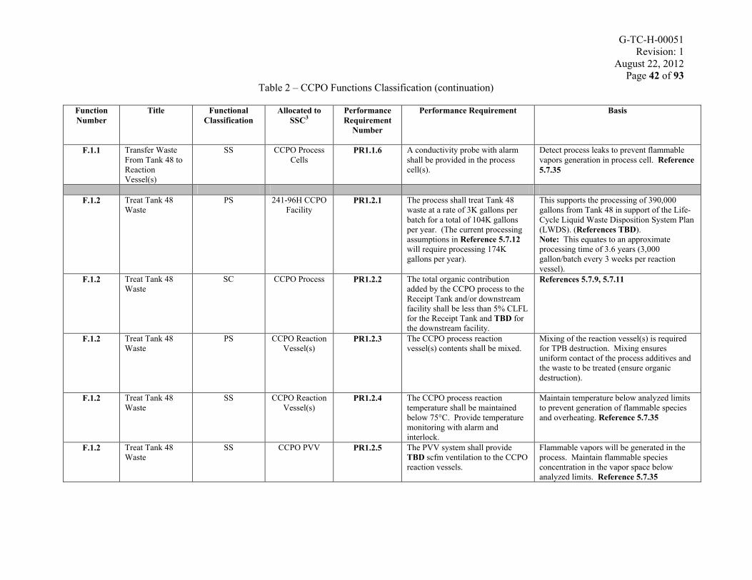
Table 2 – CCPO Functions Classification (continuation)
Function Number
Title Functional Classification
Allocated to SSC3
Performance Requirement
Number
Performance Requirement Basis
F.1.1 Transfer Waste From Tank 48 to Reaction Vessel(s)
SS CCPO Process Cells
PR1.1.6 A conductivity probe with alarm shall be provided in the process cell(s).
Detect process leaks to prevent flammable vapors generation in process cell. Reference 5.7.35
F.1.2 Treat Tank 48 Waste
PS 241-96H CCPO Facility
PR1.2.1 The process shall treat Tank 48 waste at a rate of 3K gallons per batch for a total of 104K gallons per year. (The current processing assumptions in Reference 5.7.12will require processing 174K gallons per year).
This supports the processing of 390,000 gallons from Tank 48 in support of the Life-Cycle Liquid Waste Disposition System Plan(LWDS). (References TBD).Note: This equates to an approximate processing time of 3.6 years (3,000 gallon/batch every 3 weeks per reaction vessel).
F.1.2 Treat Tank 48 Waste
SC CCPO Process PR1.2.2 The total organic contribution added by the CCPO process to the Receipt Tank and/or downstream facility shall be less than 5% CLFL for the Receipt Tank and TBD for the downstream facility.
References 5.7.9, 5.7.11
F.1.2 Treat Tank 48 Waste
PS CCPO Reaction Vessel(s)
PR1.2.3 The CCPO process reaction vessel(s) contents shall be mixed.
Mixing of the reaction vessel(s) is required for TPB destruction. Mixing ensures uniform contact of the process additives and the waste to be treated (ensure organic destruction).
F.1.2 Treat Tank 48 Waste
SS CCPO Reaction Vessel(s)
PR1.2.4 The CCPO process reaction temperature shall be maintained below 75°C. Provide temperature monitoring with alarm and interlock.
Maintain temperature below analyzed limits to prevent generation of flammable speciesand overheating. Reference 5.7.35
F.1.2 Treat Tank 48 Waste
SS CCPO PVV PR1.2.5 The PVV system shall provide TBD scfm ventilation to the CCPO reaction vessels.
Flammable vapors will be generated in the process. Maintain flammable species concentration in the vapor space below analyzed limits. Reference 5.7.35

G-TC-H-00051Revision: 1
August 22, 2012Page 43 of 93
Table 2 – CCPO Functions Classification (continuation)
Function Number
Title Functional Classification
Allocated to SSC3
Performance Requirement
Number
Performance Requirement Basis
F.1.2 Treat Tank 48 Waste
SS Electric Power PR1.2.6 Backup power (diesel generator) shall be provided to the PVV system.
Flammable vapors will be generated in the process. Maintain flammable species concentration in the vapor space below analyzed limits. Reference 5.7.35
F.1.3 Transfer Product to Receipt Tank or Downstream Facility
PS Reaction Vessels Transfer
Pumps
PR1.3.1 The transfer of waste from Building 241-96H reaction vessel(s) to the TF receipt tank or downstream facility shall maintain a minimum axial velocity of 3 ft/sec.
Maintaining this axial velocity will avoid the settling of suspended solids in the transfer system. Reference 5.7.17
F.1.3 Transfer Product to Receipt Tank or Downstream Facility
PS Electrical Disconnect
Device
PR1.3.2 Provide a manually operated electrical disconnect device capable of stopping a transfer from the reaction vessel(s) to Receipt Tank, under normal operations and following a PC-2 seismic event.
The current TF Safety Basis requires this manual means of shutting down a transfer pump by an operator. Reference 5.7.9section 4.4.1.
F.1.4 Monitor Processing
PS CCPO DCS PR1.4.1 The control system shall allow remote monitoring and recording of appropriate CCPO process parameters and equipment status, as well as configured alarm or alert conditions.
CCPO process parameters must be monitored to ensure safe and efficient operation.
F.1.5 Control Processing
PS CCPO DCS PR1.5.1 The control system shall allow remote control of appropriate CCPO process equipment as well as allowing the CCPO process to be placed in a safe state following a process upset or emergency shutdown signal.
CCPO process equipment must be controllable from a control location to ensure safe and efficient process operation.
3Allocation defines which specific system, structure or component (SSC) that will perform the allocated function.

G-TC-H-00051Revision: 1
August 22, 2012Page 44 of 93
DESIGN CONSTRAINTS AND CRITERIA3.
This section specifies design constraints. The constraints are identified by a DC before the number.
3.1 General DCs
DC.3.1.1 The design and implementation of this modification shall comply with Reference 5.3.2, Manual 11Q, "Facility Safety Document Manual".
DC.3.1.2 National Consensus Codes and Standards supplemented by SRS Engineering Standards Manual (WSRC-TM-95-1, Reference 5.4) and SRS Engineering Practices Manual (WSRC-TM-95-58, Reference 5.5), as referenced herein, shall be used as the primary source of technical criteria.
3.1.1 Permitting and Environmental Considerations
The SRR Environmental, Safety, Health & Quality Assurance (ESH&QA) in consultation with Design Authority (DA), Design Services, Construction and Startup, shall determine Federal, State, Local and Site required permits. Certain actions below (3.1.1.1 through 3.1.1.10) are required to be completed prior to the commencement of physical construction
National Environmental Policy Act (NEPA) Evaluation.3.1.1.1
Environmental Evaluation Checklist (EEC) Prescreen and final checklist completion. 3.1.1.2
Approval of a South Carolina Department of Health and Environmental Control 3.1.1.3(SCDHEC) Industrial Wastewater Treatment (IWT) permit shall be required to allow the construction tie-ins. Operation of Building 241-96H CCPO, including the transfer of material to a Receipt Tank or downstream processing facility will require an operating permit prior to startup. (References 5.1.4.1, 5.1.4.3)
Approval of a SCDHEC Bureau of Air Quality (BAQ) construction permit and 3.1.1.4modification of the site-wide Part 70 (Title V) Air Quality Permit may be required depending upon the outcome of the evaluations described below:
• Radiological National Emission Standards for Hazardous Air Pollutants (NESHAP) Evaluation to determine the need for emission control devices, and whether or not the existing Title V Air Permit will require modification, (References 5.1.4.2, 5.1.1.1, and 5.2.3) and
• Non-Radiological Pollutant Evaluations of chemicals pursuant to SCDHEC’s requirements for Standard No. 2, Criteria Pollutants, and Standard No. 8, Toxic Air Pollutants. (Reference 5.1.4.2)
G-TC-H-00051Revision: 1
August 22, 2012Page 45 of 93
National Pollutant Discharge Elimination System (NPDES) Permit evaluations for 3.1.1.5discharges through potentially affected outfalls.
Storm water management and sediment reduction (erosion control) evaluations and 3.1.1.6the development of reduction plans for land disturbances.
Power Services Utilization Permit (PSUP) Parts A, B & C, in accordance with 3.1.1.7Manual E7 Section 3.80. (Reference 5.3.3)
Site Use Clearance approval(s) in accordance with Manual 1D, Procedure 3.02, "Site 3.1.1.8Infrastructure and Services Manual".
Resource Conservation and Recovery Act (RCRA) hazardous, mixed or low level 3.1.1.9waste evaluations necessary for the disposition of spent, spilled, or abandoned materials used in the CCPO process.
A Federal Facility Agreement (FFA) System/Component Report is required for this 3.1.1.10project, to assess the secondary containment, leak detection, material compatibility, structural adequacy, and other features of the design for compliance with the terms and conditions contained in the FFA. (References 5.7.18 and 5.7.19)
CCPO process off-gas emissions from processing Tank 48 material shall comply with 3.1.1.11all Federal, State and Local requirements, including the 40 CFR 61 subpart H regulations and comply with the SCDHEC applicable Standard 2 air pollutants regulation (SC R.61-62.5 STD No. 2) and Standard 8 air pollutant regulation (SC R.61-62.5 STD No. 8).
CCPO process off-gas shall contain no RCRA hazardous (40 CFR 261) air pollutants 3.1.1.12other than the current inventory present in the Tank 48 material.
The sum of the RCRA hazardous (40 CFR 261) listed wastes, air pollutants or 3.1.1.13characteristically toxic materials discharged from the CCPO process product or off-gas shall not exceed the quantity already present in Tank 48.
The final CCPO process product output stream shall have no RCRA hazardous (40 3.1.1.14CFR 261) listed waste or characteristically toxic material, beyond what is already present in the Tank 48 feed.
The final product output stream corrosive species shall meet the TSR Corrosion 3.1.1.15Control Program requirements (Reference 5.7.10, 5.7.11)
The design shall consider the requirements of Reference 5.3.3, Manual E7 Procedure 3.1.1.161.41, Pollution Prevention in Design (U).

G-TC-H-00051Revision: 1
August 22, 2012Page 46 of 93
3.1.2 Product and Process Characteristics
Consumables3.1.2.1
The major materials that may be consumed in the CCPO process are:
• Nitric Acid• Copper nitrate• Hydrogen Peroxide• Antifoam• Sodium Hydroxide solution (Caustic Soda)
Products3.1.2.2
R&D CCPO 2005 & 2012 test data (References 5.7.2, 5.7.39) showed almost complete destruction of the TPB, biphenyl, and phenol. It is expected the CCPO product slurry will consist of less than detectable quantities of organics and other species present in the Tank 48 waste that are not destroyed in the process (e.g., Cs, actinides)
DC.3.1.2.2.1 The final product output streams shall meet the CSTF TSRs and Flammability Control Program (References 5.7.11, 5.7.24) requirements.
DC.3.1.2.2.2 The CCPO system shall not generate output streams other than the process off-gas and liquid slurry output product.
Properties of Materials3.1.2.3
Feed from Tank 48
The feed stream composition from Tank 48 will be an aqueous solution laden with
TPB and solids. Attachment 4 shall be used as a design basis for Tank 48 material
chemical composition and radionuclide inventory to be processed by the CCPO
process. Some physical, chemical, and rheological properties of the Tank 48 waste
are described in Table 3.

G-TC-H-00051Revision: 1
August 22, 2012Page 47 of 93
Table 3 - Tank 48H Material Characteristics
Characteristic Quantity Reference(1) Viscosity/Consistency 1 - 45 centipoise *
Attachment 4(2) Yield Stress 0 - 216 dynes/cm2*
Attachment 4(3) Weight % Insoluble Solids 0 – 10 wt.% *
Attachment 4(4) Density 1.00 - 1.17 *
Attachment 4(5) Maximum Particle Size 400 micron @ 5.0 g/cc
Density5.7.32
(6) Vapor Pressure 0.34-2.89 psi See Note(7) Temperature 20-35oC 5.7.32(8) pH 6.5 - 14 (1.0-1.8 M
OH-) *5.7.32
(9) Non-Newtonian Fluid (Bingham Plastic) - If ≤ 3.5 wt. % Insoluble Solids, Then Newtonian Fluid
5.7.32
* Low values are based on water.
Note: The vapor pressure range listed (0.34 to 2.89 psi) corresponds to the vapor pressure of water in the temperature range of 20 to 60 degrees C. The temperature range of Tank 48 waste is 20 to 35 degrees C. In light of the fact that actual test data is not available, this range of vapor pressure is bounding and may be used for design of subcontractor supplied components, e.g., control valves.
Process additives
22 wt. % Sodium Hydroxide (pH control)
Strong base. May react violently with acids. Mixing with nitric acid in a closed container increases temperature and pressure. Separate leak containment from nitric acid is required.
See Material Safety Data Sheet (MSDS) (Reference 5.7.25) for chemical and physical data.
50 wt. % Hydrogen Peroxide (Oxidant)
Strong oxidizing agent. Incompatible (reacts violently) with strong oxidizing agents, strong reducing
agents, and bases Separate leak containment from nitric acid and sodium hydroxide is required. Need to be stored below 35°C in light resistant containers fitted with a safety vent.
See MSDS (Reference 5.7.26) for chemical and physical data.

G-TC-H-00051Revision: 1
August 22, 2012Page 48 of 93
Copper Nitrate
Solid. Will need to be dissolved in water. Solubility of copper (II) nitrate @ 25°C in water – 145g/100g of water.
Refer to References 5.7.36, 5.7.38 for chemical and physical data.
50 wt. % Nitric Acid
Strong acid. Corrosive. Incompatible (reacts violently) with strong bases (sodium hydroxide). Separate leak containment from sodium hydroxide is required.
See MSDS (Reference 5.7.27) for chemical and physical data.
IIT B-52 Antifoam
Incompatible with strong oxidizing agents, strong acids, and bases. Separate leak containment from nitric acid, sodium hydroxide, and hydrogen
peroxide is required
See MSDS (Reference 5.7.34) for chemical and physical data.
3.1.2.3.1 Other Cold Feeds and Utilities
DC3.1.2.3.1.1 Design to provide instrument air quality requirements.
DC3.1.2.3.1.2 Portable compressor Instrument Air quality meets CCPO requirements.
DC3.1.2.3.1.3 Nitrogen contains >99.7% pure N2.
DC3.1.2.3.1.4 Steam meets 150 PSIG and 98% quality.
DC3.1.2.3.1.5 Process Water meets 3.2 mg/L Chlorides (@ 72 deg. F); 55 mg/L Alkalinity; 0.9 mg/L Calcium.
3.1.2.3.2 Process Off-Gas
The process off-gas stream shall meet 3.1.1.11, 3.1.1.12, 3.1.1.13.

G-TC-H-00051Revision: 1
August 22, 2012Page 49 of 93
Process Compatibility3.1.2.4
The PCHA will identify any controls needed to protect against process chemical hazards.
Corrosion Resistance3.1.2.5
DC.3.1.2.5.1 Process vessels, equipment and piping wetted parts shall be designed and fabricated from corrosion-resistant and erosion-resistant material, as appropriate, including acidic and alkaline environments.
DC.3.1.2.5.2 Aluminum, brass, bronze, and copper-based materials shall not come into contact with the waste or waste vapor (including off-gas). These materials are acceptable as alloying agents.
DC.3.1.2.5.3 Stainless steel and other corrosion resistant alloys used in the CCPO process and core waste transfer lines shall be corrosion evaluated per Engineering Standard 05951. Measures shall be taken to minimize stress corrosion cracking. Reference 5.4.2
DC.3.1.2.5.4 All stainless steel covered with insulating materials shall be protected from corrosion per the requirements of Reference 5.4.3, "Required Practices to Minimize Stress Corrosion Cracking of Austenitic Stainless Steel".
Radiation Resistance3.1.2.6
DC.3.1.2.6.1 Equipment and material (such as gaskets, cables, etc.,) installed in the process cells shall be capable of withstanding the total absorbed dose over design life of the CCPO process. (Reference 5.1.3.3, Part II, Section 5.4, “DOE Handbook – Design Considerations”)
3.1.3 Operations
To achieve the throughput performance requirements (Refer to Section 2.2), it is planned to operate Building 241-96H CCPO process on a continuous basis (24 hours -7 days/week). The CCPO process reaction occurs in batch mode, but chemical reaction additives could be added throughout the duration of the reaction. The process shall be controlled remotely from a DCS installed in the 3H Control Room. The 3H Control Room shall also be the interface point for transfers with Tanks 48 and the Receipt Tank
G-TC-H-00051Revision: 1
August 22, 2012Page 50 of 93
or downstream processing facility. Remote control capability shall also be provided in Building 241-96H for use during startup testing and for maintenance.
DC 3.1.3.1 The modifications to 241-96H in support of CCPO process scope shall not adversely impact the 241-96H Valve Box located to the East of 241-96H, transfer lines installed in support of the CCPO process or any other safety related SSCs. Building 241-96H shall remain qualified for seismic II/I considerations (Reference: 5.3.12).
DC 3.1.3.2 The CCPO system and controls shall be designed to contain and prevent untreated waste transfers downstream of the reaction vessels or back to Tank 48. The CCPO process system shall be designed to enable containment of untreated waste via the use of the CCPO SSCs without the need for a separate collection tank.
DC 3.1.3.3 Waste transfers are performed under the Administrative Controls and transfer requirements specified in the sending and receiving facilities Safety Basis. In general, all transfer pumps, transfer path valve box/pit covers, and transfer path valves are under Administrative Controls to prevent inadvertent transfer or unprotected transfer (i.e., inoperable leak detection or secondary containment). Detection of a leak in the CCPO process will automatically shut down transfers to and from the CCPO process.
DC.3.1.3.4 Piping between the Tank 48 vapor space and the CCPO process shall ensure the Tank 48 vapor space is isolated from the CCPO process.
The following sections describe the operating strategies of Building 241-96H CCPO and transfer systems.
Building 241-96H CCPO Operations3.1.3.1
Cold Run Operation
(TBD)
Hot Operations
(TBD)
Transfer of Feed from Tank 48 to Building 241-96H CCPO3.1.3.2
After agitation of Tank 48 for the required time using slurry pumps, the waste shall be transferred from Tank 48 to Building 241-96H through the existing transfer linefrom Tank 48 H Riser or G Riser to the reaction vessels. The transfer shall be

G-TC-H-00051Revision: 1
August 22, 2012Page 51 of 93
initiated by the 3H Control Room and shall continue until the reaction vessel(s) is filled to a predetermined level.
Transfer of Treated Waste Product to the HTF Receipt Tank or Downstream 3.1.3.3Processing Facility
The waste from the process reaction vessels is cooled before being pumped to the HTF designated receipt tank or downstream processing facility. The transfer shall be initiated by the 3H Control Room and shall continue until the level in the reaction vessel(s) has been depleted to a pre-determined level.
3.1.4 Process Waste Generation
The CCPO process may require removal of ventilation HEPA filter elements. This will be equipment disposal and not considered a new waste stream.
3.1.5 Construction Waste Constraints
DC.3.1.5.1 All solid waste generated, including construction waste, shall be handled and disposed of in accordance with SRS 1S, Waste Acceptance Criteria Manual (Reference 5.3.4).
DC.3.1.5.2 Waste minimization and spread of contamination shall be controlled in accordance with SRS 3Q, Environmental Compliance Manual and SRS 5Q, Radiological Control Manual (References 5.3.5 and 5.3.6), Chapter 4.
3.1.6 Radiological
DC.3.1.6.1 The design and installation shall meet all the requirements of Reference 5.4.4, SRS Engineering Standards 01064, “Radiological Design Requirements”, and applicable requirements of Reference 5.3.6, SRS 5Q, Radiological Control Manual (which implements the applicable requirements of 10CFR835, Reference 5.1.1.2), WSRC-TM-95-1, and Reference 5.4.5, 15889, “Confinement Ventilation Systems Design Criteria, as described in Section 3.2.2.9. The design requirement is to maintain dose to a radiological worker less than or equal to 1 rem/year.
DC.3.1.6.2 Shielding design shall meet the requirements in Reference 5.4.4.

G-TC-H-00051Revision: 1
August 22, 2012Page 52 of 93
DC.3.1.6.3 RME shall be provided as required by the "Radiation Monitoring Equipment Technical Basis Manual" (Reference 5.7.28).
DC.3.1.6.4 Where components are designed for removal or maintenance, they shall have the provision for external and internal flushing to reduce the exposure to personnel ALARA.
3.1.7 Industrial Safety
DC.3.1.7.1 Equipment design and installation shall comply with the requirements of 29 CFR 1910 (OSHA) (Reference 5.1.1.3), NFPA 101 (Reference 5.2.4) and SRS Industrial Hygiene Manual 4Q (Reference 5.3.1).
DC.3.1.7.2 The CCPO building (241-96H) is classified as a Special Purpose Industrial Occupancy, per NFPA 101, for egress and general life safetyrequirements (Reference 5.2.4).
DC.3.1.7.3 Safety Shower and Eyewash Stations shall be designed and installed in accordance with Reference 5.3.7, “Employee Safety Manual”, Procedure 52.
DC.3.1.7.4 Material handling locations shall be designed to minimize tasks and reduce potential back injury (Reference 5.1.3.4, DOE Order 440.1A).
DC.3.1.7.5 Workplace monitoring for potential asphyxiation hazards shall conform to Reference 5.4.1, "Asphyxiation Design and Evaluation Limits".
DC.3.1.7.6 Workplace monitoring shall be provided for potential oxygen-rich atmosphere to prevent explosions in accordance with Reference 5.3.8, Manual 13B, Chemical Management Manual, Procedure 2.5, "Compressed Gases and Cryogenic Fluids: Purchasing, Handling, Storage and Use".
3.1.8 Reliability, Availability, Maintainability, and Inspectability (RAMI) Requirements
DC.3.1.8.1 The design life of the CCPO process in Building 241-96H shall be 5 years for an operating life of 4 years. A 2 year design life is acceptable for existing Tank 48 slurry pumps, and reaction vessel pumps due to accessibility to replacement pumps or parts.
DC.3.1.8.2 Components requiring maintenance shall be capable of being removed from service for routine and non-routine maintenance.
DC.3.1.8.3 Components requiring inspection, operator monitoring, calibration and physical operation shall be installed in a location that allows those operations to be performed with minimal exposure to safety hazards and shall meet ALARA requirements.

G-TC-H-00051Revision: 1
August 22, 2012Page 53 of 93
DC.3.1.8.4 The design of all components anticipated to contact any waste form (liquid or solid) shall provide for flushing of surfaces to facilitate decontamination and removal of contaminants.
DC.3.1.8.5 Where feasible, equipment shall be instrumented such that loops and sensors can be maintained, calibrated, and replaced without requiring entry into a radiation area, thereby reducing the radiation exposure to the worker (ALARA).
DC.3.1.8.6 The process design shall provide access to all components requiring maintenance and shall be based on maintenance practices using ALARA techniques such as extended length tools and quick disconnects.
DC.3.1.8.7 The following solutions shall be used for decontamination to reduce radiation dose prior to performing maintenance activities:
a. Process Water
b. IW
c. Nitric acid
d. Sodium Hydroxide/Caustic
Use of decontamination solutions not listed above requires an evaluation and approval by DA.
3.1.9 Human Factors
DC.3.1.9.1 HFE shall be an integral part of the Control Room and operator interface design, per NUREG 0700, “Human System Interface Review Guidelines”, (Reference 5.2.2). NUREG 0700, “Human System Interface Review Guidelines”, (Reference 5.2.2) and “DeltaV Design Standards Document”, (Reference 5.7.21) shall be applied for user operability, applications, maintenance, accessibility, testability, dependability, and standardized conventions and nomenclature.
DC.3.1.9.2 The design shall apply the requirements of Manual 4Q Section 502 “Thermal Stress Management” (see section F of Section 502).
3.1.10 Quality Assurance
DC.3.1.10.1 A Quality Assurance Plan consistent with the SRS 1Q, Quality Assurance Manual shall be developed (Reference 5.3.9).

G-TC-H-00051Revision: 1
August 22, 2012Page 54 of 93
3.2 SSC Configuration and DCs
3.2.1 Civil and Site Work
DC.3.2.1.1 Structures and system/component supports and anchors associated with this modification shall be designed and constructed in accordance with Reference 5.4.6, WSRC-TM-95-1, Standard 01060, “Structural Design Criteria” and 5.4.7, WSRC-TM-95-1, Standard 01061, “Qualification of Systems, Equipment & Components for Natural Phenomena Hazards”. For the TTP, the structural code of record invoked is the IBC per Reference 5.4.6, and the code year is 2006 per the project criteria documents.
DC.3.2.1.2 Civil and site work design shall comply with Reference 5.4.8, WSRC-TM-95-1, and Standard 01110 “Civil Site Design Criteria”.
DC.3.2.1.3 NFPA 241, "Standard for Safeguarding Construction, Alteration, and Demolition Operations", Reference 5.2.5, shall be invoked where applicable.
3.2.2 Mechanical
General3.2.2.1
DC.3.2.2.1.1 Materials shall be compatible with or able to withstand the process solution, radiation exposure, or chemicals to which they are exposed.
DC.3.2.2.1.2 Components (piping, storage tanks and instrumentation) susceptible to freezing shall be provided with freeze protection.
DC.3.2.2.1.3 Any gaseous or vapor pressure relief device discharge shall be directed into a suitable ventilation system, upstream of a suitable HEPA filter. Any liquid pressure relief device discharge shall be directed into a suitable confinement without discharging into the process room of Building 241-96H.
DC.3.2.2.1.4 The design shall consider using components that conform to the Site standard components list in Reference 5.4, SRS Engineering Standards Manual, Attachment 4.
DC.3.2.2.1.5 Engineering units shall be per Table 4 below. Preferred units are marked with an asterisk, “***”
DC.3.2.2.1.6 The ASHRAE Handbook, Reference 5.2.6, shall be used to determine minimum process room temperature inside building 241-96H (for design basis input).

G-TC-H-00051Revision: 1
August 22, 2012Page 55 of 93
Table 4 - Preferred Engineering Units
Symbol Name Symbol NameVelocity Radiation Dosefps feet per second *** mrad milliradfpm feet per minute mrem millirem ***rpm revolutions per minute *** R roentgen
Flow rates RadioactivityGPM gallons per minute *** Ci curiegph gallons per hour mCi millicuriecfs cubic feet per second µCi microcuriescfm standard cubic feet per minute *** dpm Disintegrations per minute ***
Ci/gal Curies per gallonPressure or Stress
Densitypsi pounds per square inch *** g/cm3 grams per cubic centimeter ***ksi 1000 pounds per square inch lbs/ft3 pounds per cubic footksf 1000 pounds per square foot
ViscosityDifferential Pressure cP centipoise ***inwc inches of water column ***
Power/Energy
ConcentrationHp horsepower ***
g/ml grams per milliliter Btu British thermal unitsppb parts per billion
Heat Flowppm parts per million *** Btu/hr British thermal units per hour
Temperature Weights˚C degrees Celsius *** oz. ounce˚F degrees Fahrenheit lbs. pounds ***
Levelkips 1000 pounds
In. Inches *** T Ton

G-TC-H-00051Revision: 1
August 22, 2012Page 56 of 93
Piping3.2.2.2
DC.3.2.2.2.1 All new piping design or modifications to existing piping shall comply with the requirements of Reference 5.2.7, “ASME B31.3, Process Piping”, Reference 5.4.9, SRS Engineering Standard 15060, and Reference 5.5.1, Engineering Guide 15060-G, “Application of ASME B31.3”.
DC.3.2.2.2.2 All components that can come in contact with the waste shall be designed to avoid the collection or hold-up of solids and liquids, both externally and internally (e.g. provide drain back features, smooth surface finish and geometry, backing rings in vertical sections required for closure and tie-in joints, etc.).
DC.3.2.2.2.3 For personnel safety, all hoses shall have hose whips installed at all connections and be properly restrained to prevent whipping should a hose rupture.
DC.3.2.2.2.4 If hoses are used in the design, the hoses shall be radiation resistant, explosion and fire resistant, non-combustible, abrasion resistant, and chemically tolerant to the environment and liquids the hoses will be exposed and shall comply with Engineering Guide 15062-G.
DC.3.2.2.2.5 Piping shall be supported or restrained to avoid vibration resulting from the flow of service medium. Transient loads under all modes of operation shall be considered in the design of the supports.
DC.3.2.2.2.6 Equipment supports subjected to vibration shall be designed to avoid resonance between the operating frequency and the natural frequency of the equipment support.
DC.3.2.2.2.7 Non-interchangeable connections complying with Reference 5.2.8, CGA V-1, “Compressed Gas Cylinder Valve Outlet and Inlet Connections”, shall be used for service equipment filling, charging, and draining connections for all gases.
DC.3.2.2.2.8 Double isolation valves, providing “block and bleed” capability, shall be provided on hazardous energy piping such as steam or air to ensure positive isolation and to permit maintenance.
DC.3.2.2.2.9 Fluid piping systems shall include physical design features to prevent damage from “hydraulic” transients in liquid and gas systems.
DC.3.2.2.2.10 Radioactive liquid samplers shall have a return (or recirculation) lines back to an appropriate process vessel. Sampling lines shall be sloped to "passively" drain back to sending tank.
DC.3.2.2.2.11 Radioactive sample piping configurations shall prevent siphoning from the process vessel.

G-TC-H-00051Revision: 1
August 22, 2012Page 57 of 93
DC.3.2.2.2.12 DW shall be supplied by separate, dedicated service lines and not combined with other water systems.
DC.3.2.2.2.13 Any connection between waste process and utility or cold feed systems shall be designed to prevent back-flow. Back flow prevention shall maintain contamination inside the enclosure of the CCPO.
DC.3.2.2.2.14 The provisions of ASME B31.11 Slurry Piping Standard shall be considered with respect to erosion resistance of piping and vessels to the process flows.
DC.3.2.2.2.15 A connection shall be provided to allow Instrument Air to be supplied by a portable system in the event of an upset in the Instrument Air supply.
Tanks3.2.2.3
Process Tanks
DC.3.2.2.3.1 Process tanks shall be properly grounded to prevent potential ignition source from static charges.
DC.3.2.2.3.2 If existing tanks are utilized by this project, they shall be evaluated by Engineering as being acceptable for use.
DC.3.2.2.3.3 Mixing of the waste in the reaction vessels may cause foaming of the waste. A method for foam detection shall be provided.
DC.3.2.2.3.4 For the existing reaction vessels, the operating level ranges from the 2 inch low level (min) pseudo bottom of the tanks to 80 inches high level (max).
DC.3.2.2.3.5 Loop seals shall be considered for pressure protection and as a vapor barrier in the overflow path.
DC.3.2.2.3.6 Pressure protection for all equipment and components shall comply with the requirements of Reference 5.4.10, “Pressure Equipment Protection Requirements”.
Bulk Chemical Storage & Delivery Tanks
DC.3.2.2.3.7 Process tanks shall be properly grounded to prevent potential ignition source from static charges.
DC.3.2.2.3.8 If existing tanks are utilized by this project, they shall be evaluated by Engineering as being acceptable for use.

G-TC-H-00051Revision: 1
August 22, 2012Page 58 of 93
DC.3.2.2.3.9 Bulk chemical storage and delivery system vessel overflows and tank drains shall be directed to a location where material can be captured and handled administratively.
DC.3.2.2.3.10 All bulk chemical storage and delivery tanks shall be fitted with secondary containment capable of containing the entire anticipated leak volume of the tank.
DC.3.2.2.3.11 Loop seals shall be considered for pressure protection and as a vapor barrier in the overflow path.
DC.3.2.2.3.12 Pressure protection for all equipment and components shall comply with the requirements of Reference 5.4.10, “Pressure Equipment Protection Requirements”.
WTS Piping and Additional Piping Constraints3.2.2.4(WTS piping shall terminate at the reaction vessel(s) inlet and commence at the reaction vessel(s) transfer pump discharge).
DC.3.2.2.4.1 All waste transfer system core piping and components shall be 304L or 316L. Such piping shall be seamless and conform to ASTM A312 and be a minimum of Schedule 40S.
DC.3.2.2.4.2 Waste transfer lines inside 241-96H and outside the CCPO process cells shall be jacketed.
DC.3.2.2.4.3 Jacketed piping shall consist of a stainless steel core pipe surrounded by a carbon steel jacket.
DC.3.2.2.4.4 Core pipe and jacket shall be welded construction.
DC.3.2.2.4.5 Spacers between core pipe and jacket shall be provided. Liquid flow path shall not be impeded.
DC.3.2.2.4.6 Leak detection capability shall be incorporated into the design of liquid radioactive waste transfer lines. Leak detection shall detect the failure of the primary containment boundary, the occurrence of a waste release, or the accumulation of liquid or precipitation in the secondary containment system for double walled transfer lines. Secondary containment shall have capability to be drained by gravity to primary containment.
DC.3.2.2.4.7 Liquid waste transfer line core pipes, up to the 241-96H reaction vessel(s) process cell inlet/outlet nozzle blocks, shall be limited to a bounding design pressure of 260 psig (Reference 5.7.29) and a temperature of 75°C (Reference 5.7.10). Waste transfer core pipes are also subject to the additional requirements for SC and Category M

G-TC-H-00051Revision: 1
August 22, 2012Page 59 of 93
fluid service piping, with exceptions per the FFA. (Reference 5.4.9, Section 5.5).
DC.3.2.2.4.8 Liquid waste transfer jacket pipes, up to the 241-96H reaction vessel(s) process cell inlet/outlet nozzle blocks, shall be limited to a bounding design pressure of 150 psig (Reference 5.7.29) and a temperature of 75°C (Reference 5.7.10). Waste transfer jacket pipes are also subject to the additional requirements for SS and Normal fluid service piping, with exceptions per the FFA. (Reference 5.4.9, Section 5.5).
DC.3.2.2.4.9 All new waste transfer piping design or modifications to existing transfer lines and CCPO process piping containing waste, shall comply with the requirements of Reference 5.2.9, “ASME B31.3, Process Piping” and Reference 5.4.9, SRS Engineering Standard 15060, Reference 5.5.1Engineering Guide 15060-G, “Application of ASME B31.3” and the Reference 5.7.18 Federal Facilities Agreement.
DC.3.2.2.4.10 The design shall consider the use of existing transfer lines inside Building 241-96H and in the vicinity of the building.
DC.3.2.2.4.11 Waste transfer lines design shall consider abrasive characteristics of the waste material.
DC.3.2.2.4.12 The transfer line core pipe from Tank 48 Riser H transfer pump to the CCPO process shall be capable of being flushed.
DC.3.2.2.4.13 The transfer line core pipe from Tank 48 Riser G transfer pump to the CCPO process shall be capable of being flushed.
DC3.2.2.4.14 Transfer line WTS-L-1554 is not available for use.
DC.3.2.2.4.15 The design shall prevent siphons, or include the means to stop a siphon for all waste and non-waste liquids.
Tank 48 Waste Transfer Pump and Riser Cover3.2.2.5
DC.3.2.2.5.1 The existing Tank 48 waste transfer pumps and riser covers shall be used for this project, Reference 5.7.23.
DC.3.2.2.5.2 The Tank 48 Riser H Waste Transfer Pump shall have local reset/stop in addition to control from the 3H Control Room.
DC.3.2.2.5.3 The Tank 48 Riser G Waste Transfer Pump shall have local reset/stop in addition to control from the 3H Control Room.

G-TC-H-00051Revision: 1
August 22, 2012Page 60 of 93
Pumps and Agitators3.2.2.6
DC.3.2.2.6.1 Materials selected for pumps and agitators shall be compatible with the fluid streams handled.
DC.3.2.2.6.2 If commercial pumps/agitators are not available, pumps/agitators shall be designed and manufactured per National Standards listed in Reference 5.2.9.
DC.3.2.2.6.3 Pumps in radiation areas shall not use Teflon, Viton, or other materials as seals, diaphragms, or gaskets that may breakdown due to radiation exposure.
DC.3.2.2.6.4 Pumps moving radioactive fluids from tanks shall be installed within the tanks, to the extent practicable, to reduce the need for shielding pumps.
DC.3.2.2.6.5 Pumps and agitators shall be designed to preclude, to the extent practical, those failure modes resulting in missiles capable of penetrating process vessels and compromising containment integrity.
DC.3.2.2.6.6 All tank agitators shall be controlled by VFDs.
DC.3.2.2.6.7 If a recirculation eductor or transfer jet is used, its design and location shall be sufficiently below liquid level and with the appropriate recirculation flow to prevent aerosolization inside the vessel.
Valves3.2.2.7
DC.3.2.2.7.1 Valves shall be compatible to the specific application requirements and comply with the requirements of Reference 5.2.7, ASME B31.3, “American Society of Mechanical Engineers, Process Piping”, as either listed or unlisted components, as required by B31.3 and 15060-G, “Application of ASME B31.3” Reference 5.5.1.
DC.3.2.2.7.2 Isolation valves shall be provided to isolate equipment, or appurtenances for ease of maintenance.
DC.3.2.2.7.3 Valves requiring manual operation during normal operations shall be designed to be manually operated from outside the secondary confinement and associated shielding.
DC.3.2.2.7.4 Valves in radioactive service or radiation field shall not use Teflon, Viton, or other materials as seals or gaskets that may breakdown due to radiation exposure.

G-TC-H-00051Revision: 1
August 22, 2012Page 61 of 93
DC.3.2.2.7.5 Valves used to control system flushing shall have valve actuators that allow manual operation from outside the secondary confinement and associated shielding.
DC.3.2.2.7.6 Manual valves shall have local indication of valve position (i.e. “open” and “closed”) and direction of operation provided at the operating location. The convention shall be counterclockwise to open.
DC.3.2.2.7.7 Automatic remote valves shall have their local valve position indicator visible for camera inspection.
Fire Protection3.2.2.8
Building 241-96H CCPO shall meet the fire protection requirements of Reference 5.7.20, “SRR Standards/Requirements Identification Document, Functional Area 12, Fire Protection, Revision 09-14”, and Reference 5.4.11, “SRS Fire Protection Design Criteria”, and the applicable scope of DOE-STD-1066-99. The facility fire hazard category will be High with the CCPO installed and operating. Any new building construction shall meet the requirements of Reference 5.2.10, NFPA 220, "Standard for Types of Building Construction".
The HTF FHA will be updated to reflect the installation and operation of Building 241 96H CCPO and the methodology for maintaining and/or providing fire detection and suppression. The following specific requirements shall be met:
DC 3.2.2.8.1 Tanks, piping, vessels, and enclosures that have the potential to contain flammable concentrations of flammable gases, vapors, mists, dusts, or hybrid mixtures shall comply with NFPA 69.
DC 3.2.2.8.2 Tanks, piping, vessels, and pressurized equipment that contain compressed gases or cryogenic fluids shall comply with NFPA 55, "Compressed Gases and Cryogenic Fluids Code", Reference 5.2.11.
DC 3.2.2.8.3 Installation of sprinkler system (if necessary) shall comply with NFPA 13, "Standard for the Installation of Sprinkler Systems", Reference 5.2.12. The sprinkler system must be extended to ensure that there are no obstructions to water flow. This includes sprinkler coverage inside the process enclosures or another means to suppress fire in the enclosures. In addition, the type of sprinkler head must be reviewed and a hydraulic calculation performed to ensure sufficient water supply.
DC 3.2.2.8.4 Fire alarm system shall comply with NFPA 72, "National Fire Alarm and Signaling Code", Reference 5.2.13.
DC 3.2.2.8.5 Stainless steel or noncombustible corrosion resistant equipment should be provided for all ventilation metal parts required for fire

G-TC-H-00051Revision: 1
August 22, 2012Page 62 of 93
protection where components in the ventilation system are exposed to corrosive atmospheres. They should be designed either with stainless steel or other non-reactive materials to ensure their resistance to the harmful effects of corrosion. Where corrosion resistant or stainless steel fire protection product is required and that product is not available as a listed product from any manufacturer, the substitution of one product for another is acceptable provided that the replacement product is equivalent, based on an engineering analysis.
DC 3.2.2.8.6 A redundant fire protection system is needed throughout the building.
HVAC 3.2.2.9
Three confinement ventilation zones shall be provided at the end of the HVAC section. The exhaust flow from any zone shall pass through HEPA filtration before release to the environment.
Table 5 - Confinement Zones
Confinement Area Building 241-96H
Primary Confinement
• Process tanks, vessels, waste containing equipment and interconnecting process piping
• Sample lines & vial(s)• PVV
Secondary Confinement• 241-96H Process Cell #1/#2 • Sample Station Enclosure• Ventilation System
Tertiary Confinement • Building 241-96H
The primary confinement zone consists of the process tanks, vessels and interconnecting piping. This zone conveys process off-gases to the 241-96H South stack for discharge to the atmosphere via HEPA filtration.
The secondary confinement zone consists of the annular volume between the Primary Zone and the Process Cell #1 & #2 containment. This system confines any potential release of hazardous material from the primary confinement to minimize potential contamination within Building 241 96H Tertiary Zone. Flow into the secondary zone shall be cascaded from the Tertiary Zone. Air from the 241-96H process cells is exhausted by the existing 241-96H south side building ventilation system to the south stack.
The tertiary confinement zone is the 241-96H process cell truck bay and remaining building 241-96H north side rooms outside the secondary confinement. Air from the 241-96H process cell truck bay is exhausted by the existing 241-96H south side

G-TC-H-00051Revision: 1
August 22, 2012Page 63 of 93
building ventilation system to the south stack. Air from the remaining north side rooms is exhausted by the existing 241-96H north side building ventilation system to the north stack. The Tertiary zone acts as the final barrier to prevent the release of airborne hazardous material to the environment.
The design shall utilize as much of the existing HVAC equipment as practical. The design shall provide an integrated system such that all three zones discharge through the existing stacks. (Reference 5.6.37)
3.2.2.9.1 General DCs
DC.3.2.2.9.1.1 Building 241-96H HVAC shall be designed to the requirements of Reference 5.4.5 SRS Engineering Standard 15889, “Confinement Ventilation Systems Design Criteria”.
DC.3.2.2.9.1.2 A source of backup power (safety related) shall be provided for the ventilation system.
3.2.3 Electrical
General3.2.3.1
DC.3.2.3.1.1 The electrical design and electrical equipment procurement for this modification shall comply with Reference 5.2.14, NFPA 70 “National Electrical Code”; Reference 5.2.15, ANSI/IEEE C2 “National Electrical Safety Code”; Reference 5.2.16, IEEE 399 “Recommended Practice for Industrial and Commercial Power Systems Analysis – IEEE Brown Book”,and Reference 5.2.17, IEEE 141, “Recommended Practice for Electric Power Distribution for Industrial Plants-IEEE Red Book”.
DC.3.2.3.1.2 Electrical design shall conform to Reference 5.4.12, SRS Engineering Standard 16050 “SRS Electrical Design Criteria”.
DC.3.2.3.1.3 All electrical materials and equipment shall be tested and listed by Underwriters Laboratories (UL) or approved by Factory Mutual Engineering and Research (FM) or a similarly recognized national organization. If any electrical equipment is not listed, Reference 5.5.2, SRS Engineering Guide 16980-G, “Assessment of Listed/Non-Listed Electrical Equipment for Use at SRS”, shall be used to assess and ensure a safety level equivalent to “listed” equipment.
DC.3.2.3.1.4 Electrical grounding of equipment shall comply with Reference 5.5.3, SRS Engineering Guide 16056-G, “Installation of Grounding Systems”.

G-TC-H-00051Revision: 1
August 22, 2012Page 64 of 93
DC.3.2.3.1.5 Installation and termination of all wires and cables shall comply with Reference 5.5.4, SRS Engineering Guide 16052-G, “Installation of Electrical Wires, Cables, and Terminations”.
DC.3.2.3.1.6 Electric power systems and equipment voltage ratings shall comply with Reference 5.2.18, ANSI/NEMA C84.1, “Electric Power Systems and Equipment-Voltage Ratings (60 Hertz)”.
DC.3.2.3.1.7 One of the following methods shall be used for seismic qualification (per Reference 5.2.19, IEEE STD-344, “Institute of Electrical and Electronics Engineers, Recommended Practices for Seismic Qualification of Class 1E Equipment for Nuclear Power Generating Stations”) of SS systems and components that must continue to function during or following a seismic event:
1. Qualification by test under simulated seismic conditions or,
2. Qualification by a combination of test and analysis, or,
3. Qualification through the use of experience data with prior approval of DA.
DC.3.2.3.1.8 Electric motors shall comply with Reference 5.2.20, NEMA MG-1, “Motors and Generators”.
DC.3.2.3.1.9 Non-fiber optic signal cables shall not be run in close proximity to power cables or other cables that could induce voltages into the signal cables.
DC.3.2.3.1.10 Electrical design shall comply with Reference 5.2.21, IEEE 739, “Recommended Practice for Energy Management in Industrial and Commercial Facilities – IEEE Bronze Book” for the application of energy conservation requirements and considerations.
DC.3.2.3.1.11 General equipment grounding systems shall comply with Reference 5.2.14, NFPA 70, National Electrical Code, Article 250 and Reference 5.2.22, IEEE 142, “Recommended Practice for Grounding of Industrial and Commercial Power Systems – IEEE Green Book”.
DC.3.2.3.1.12 Grounding for computer/control and data processing equipment power shall comply with Reference 5.2.14, NFPA 70, National Electrical Code, Article 645; Reference 5.2.23 NFPA 75, “Standard for the Protection of Electronic Computer/Data Processing Equipment”; Reference 5.2.24, IEEE 1050, “Guide for Instrumentation and Control Equipment Grounding in Generating Stations”; and Reference 5.2.25, IEEE 1100, “Recommended Practice for Powering and Grounding Sensitive Electronic Equipment – IEEE Emerald Book”.
DC.3.2.3.1.13 Design shall use Reference 5.2.14, NFPA 70, National Electrical Code, Article 500 & 501 and Reference 5.2.26, NEMA 250, “Enclosures for Electrical Equipment (1000 volts Maximum)” to obtain the design requirements for electrical system wiring and for selecting motor enclosure

G-TC-H-00051Revision: 1
August 22, 2012Page 65 of 93
types for Class 1, Division 1 & 2 locations where fire or explosion hazards may exist.
DC.3.2.3.1.14 The design shall use Reference 5.2.27, IEEE 841, “Standard for Petroleum and Chemical Industry – Severe Duty Totally Enclosed Fan-Cooled (TEFC) Squirrel Cage Induction Motors – Up To and Including 370kW (500 Hp)”, to obtain the design requirements for a severe duty totally enclosed fan-cooled motor.
DC.3.2.3.1.15 The design shall comply with Reference 5.2.14, NFPA 70, National Electrical Code, Article 240 for over current protection requirements; Reference 5.2.28, IEEE C37.90, “Standard for Relay Systems Associated with Electric Power Appliances”; Reference 5.2.29, IEEE C37.91, “Guide for Protective Relay Applications to Power Transformers”, and Reference 5.2.30, IEEE C37.95, “Guide for Protective Relaying of Utility-Consumer Interconnections”, for protection relaying requirements; Reference 5.2.31, IEEE 242, “Recommended Practice for Protection and Coordination of Industrial and Commercial Power Systems” and Reference 5.2.32, IEEE 1015, “Recommended Practice for Applying Low-Voltage Circuit Breakers Used in Industrial and Commercial Power Systems – IEEE Blue Book”.
DC.3.2.3.1.16 Lightning protection for areas/facilities shall comply with Reference 5.2.33, NFPA 780, “Standard for the Installation of Lightning Protection Systems” and Reference 5.2.14, NFPA 70, National Electrical Code, Article 280.
DC.3.2.3.1.17 AC motor protection shall comply with Reference 5.2.14, NFPA 70, National Electrical Code, Article 430, and Reference 5.2.31, IEEE 242, “Recommended Practice for Protection and Coordination of Industrial and Commercial Power Systems”.
3.2.4 Instrumentation and Controls
General3.2.4.1
DC.3.2.4.1.1 Components with controllers shall have their process variables tuned to provide stability during normal and abnormal conditions.
DC.3.2.4.1.2 Leak detection capability with DCS alarms shall be provided. The process cells shall be equipped with conductivity probes with DCS alarms.
DC.3.2.4.1.3 Where feasible, preconfigured field bus cables or applicable cable connectors shall be utilized to reduce additional wiring and cable landing in the field. Design shall be in accordance with ANSI/ISA 50.02 (Reference 5.2.34).
DC.3.2.4.1.4 Field and DCS temperature displays shall be standardized to indicate the preferred units specified in DC 3.2.2.1.7, Table 4.

G-TC-H-00051Revision: 1
August 22, 2012Page 66 of 93
DC.3.2.4.1.5 A minimum of 2 spare fibers shall be available in any newly installed segment of the communication path between 241-96H and 241-2H (3H Control Room).
DC.3.2.4.1.6 The design shall meet the requirements of Reference 5.2.35 IEEE 1016, “Recommended Practice for Software Design Descriptions”
DC.3.2.4.1.7 The software design for the CCPO process control system shall be consistent with the LWCN DeltaV DCS and comply with DeltaV Control System Design Standards (References 5.7.21).
DC.3.2.4.1.8 The process control and monitoring functions (hardware and software) shall be a failsafe design per Engineering Guide 16941-G (Reference 5.5.5).
DC.3.2.4.1.9 Existing Emerson DeltaV DCS will be used to monitor and control the CCPO process and balance of plant. Existing I/O is sufficient to support CCPO process.
DC.3.2.4.1.10 Field instrumentation and control devices shall utilize the following fieldbus technologies for control system interface:
• AS-I – shall be used for digital inputs and outputs to and from the DeltaV controller(s) to connect discrete devices including but not limited to: limit switches, pressure switches, conductivity probe switches, etc.
• Foundation Fieldbus shall be utilized for analog inputs and outputs including but not limited to: level transmitters, pressure transmitters, flow transmitters, etc.
• DeviceNet shall be utilized to handle intelligent devices including but not limited to: variable frequency drives, power controllers, motor control centers, etc.
• Other technologies may be considered if required by a particular instrument or control device.
DC.3.2.4.1.11 The CCPO process equipment shall be designed to fail to a safe state per Engineering Guide 16941-G (Reference 5.5.5).
DC.3.2.4.1.12 Interlocks and alarms shall be designed to meet failsafe concept by being configured such that operation outside of defined parameters or failure will cause the component to go to the failsafe mode/position and interlock coupled components to the failsafe mode/position (e.g., tripping relays and alarm relays shall be energized for a normal condition and upon loss of power to tripping relays shall result in the safe shutdown of the process).
Monitoring3.2.4.2
During the operation of 241-96H CCPO process, selected process variables shall be monitored. The resulting data will be used to optimize the process.

G-TC-H-00051Revision: 1
August 22, 2012Page 67 of 93
DC.3.2.4.2.1 Data monitoring shall be recorded in the Primary Control Room in Building 241-2H (3H Control Room) and displayed on both the operator workstation in the 3H Control Room and the DeltaV Maintenance Workstation in 241-96H. Data monitoring shall be recorded on the existing PI system.
Design shall provide for monitoring as identified in Table 6 as follows:
Table 6 – Monitoring Requirements
Location Type JustificationFacility
(Building) Exhaust Stack
Effluent Monitoring 241-96H exhaust stack shall have a radiation monitor to perform continuous sampling at a sampling location that meets the requirements of ANSI N13.1 (Reference 5.2.36) for a PIC 2 source.
Various Area Radiation Monitoring (ARM)
ARMs are required in the following areas: Reaction Vessel(s) – (1 required)
PVV Off-gas monitoring Off-gas monitoring of the reaction vessels vapor effluent.
This section defines the process variables and equipment status information (at a minimum) that will require monitoring.
CCPO Process Operation
DC.3.2.4.2.2 For balance-of-plant and SRR supplied SSCs, as a minimum, the following process parameters shall be monitored:
• Reaction Vessel(s) temperature with alarms and interlock, pH and flowrates , levels, Specific Gravity
• Tank levels with high level alarm • Process cell sump conductivity probe alarms• System mass balance (only for those parameters where measurement by
operator is not practical)• Flow, temperature, and pressure in off-gas system and existing PVV
system. • Stack high activity (a local probe with radiation monitor and provision
for sampling shall be installed) with local and DCS alarms• Stack sample no flow or low flow• ARMs• HVAC• Chilled water system flow, pressure and supply temperature• Chilled water system cooling path radiation level• Process water flows and totalized flow to reaction vessels(s)• Monitoring as specified by Industrial Hygiene (IH)• Exhaust stack effluent radiation monitoring

G-TC-H-00051Revision: 1
August 22, 2012Page 68 of 93
• Cold chemicals depletion rate vs. reaction vessel accumulation rate or flow meter rate
• Cold chemical dike area sump level indication
Waste Transfers from Tank 48 to 241-96H
DC.3.2.4.2.3 Waste transfer from Tank 48 to 241-96H shall be monitored by the 3H Control Room.
DC.3.2.4.2.4 During the waste transfers from Tank 48 to Building 241-96H CCPO, as a minimum, the following shall be monitored:
• Reaction Vessel(s) level• Transfer path leak detection• Reaction Vessel(s) temperature• Process cells sump level alarm status• Tank 48 liquid level• Process cell(s) transfer Manual Operating Valve (MOV) position
Addition of Cold Chemicals to the Reaction Vessels
DC.3.2.4.2.5 During the transfer of cold chemicals from the bulk chemical storage and delivery system to the CCPO reaction vessels, as a minimum, the following shall be monitored:
• Reaction Vessel(s) level• Transfer path leak detection• Reaction Vessel(s) temperature• Process cells sump level alarm status• Cold Chemical Depletion Rate vs Vessel Accumulation Rate or Flow
Meter Rate• Cold Chemical Dike Area Sump Level Indication• Process additives flows and totalized flow to reaction vessel(s)• pH of Reaction Vessel(s)• Foam detection
Product Transfers from 241-96H to the Receipt Tank or Downstream Processing facility
DC.3.2.4.2.6 The product transfers from 241-96H to the Receipt Tank or downstream processing facility shall be monitored by the 3H Control Room.
DC.3.2.4.2.7 The following process variables and equipment status information shall be monitored during product transfers from 241-96H to the Receipt Tank:
• Reaction Vessel(s) liquid level• TF Receipt Tank or downstream facility liquid level• Transfer path leak detection

G-TC-H-00051Revision: 1
August 22, 2012Page 69 of 93
• Reaction vessel(s) transfer pump status• Process cell transfer path MOV position• Process cell sump level alarm status• 241-96H valve box leak detection• Permissive(s)
Control3.2.4.3
This section describes the process variables and equipment function that require control.
CCPO Process Operation
DC.3.2.4.3.1 Primary control of the 241-96H CCPO process shall be from the 3H Control Room. The DeltaV Maintenance Workstation in 241-96H shall also be capable of process startup/shutdown/operation during testing or maintenance.
DC.3.2.4.3.2 The DCS shall provide both automatic and manual control/shutdown of the CCPO process.
DC.3.2.4.3.3 For balance-of-plant and SRR supplied SSCs, as a minimum, the following process parameters shall be controlled by the DeltaV DCS:
• Reaction Vessel(s) agitators• Reaction Vessel(s) transfer pumps• Off-gas blower speed• Nitric Acid addition• Catalyst addition• Hydrogen peroxide addition• Antifoam addition• Caustic addition• HVAC Control• Reaction Vessel(s) transfer control• Tank 48 transfer control
DC.3.2.4.3.4 Waste feed to the process shall be monitored to stop upon the detection of a leak into any process cell secondary containment or confinement.
Feed Transfers from Tank 48 to Reaction Vessel(s)
DC.3.2.4.3.5 The 3H Control Room shall have primary responsibility for controlling waste transfers from Tank 48 to the reaction vessel(s).

G-TC-H-00051Revision: 1
August 22, 2012Page 70 of 93
DC.3.2.4.3.6 During the transfer of waste feed from Tank 48 to the reaction vessel(s), the 3H Control Room shall control the Tank 48 transfer pump operation (START/STOP).
DC.3.2.4.3.7 Transfer of waste feed from Tank 48 H Riser to the reaction vessel #1 shall be interlocked to stop the transfer upon a reaction vessel high liquid level or a Process Cell #1 sump conductivity probe alarm.
DC.3.2.4.3.8 Transfer of waste feed from Tank 48 Riser G to the reaction vessel #2 shall be interlocked to stop the transfer upon a reaction vessel high liquid level or a Process Cell #2 sump conductivity probe alarm.
DC.3.2.4.3.9 Transfer of waste feed from Tank 48 Riser H to the reaction vessel #1 shall be DCS software controlled in a manner that automatically stops a transfer prior to reaching high liquid level alarms or interlocks.
DC.3.2.4.3.10 Transfer of waste feed from Tank 48 Riser G to the reaction vessel #2 shall be DCS software controlled in a manner that automatically stops a transfer prior to reaching high liquid level alarms or interlocks.
Product Transfers from 241-96H to Receipt Tank or Downstream Processing Facility
DC.3.2.4.3.11 The product transfers from the reaction vessel(s) to the receipt tank or downstream processing facility shall be controlled by the 3H Control Room.
DC.3.2.4.3.12 The transfer shall be terminated upon receipt of a Process Cell #1 or 241-96H valve box sump conductivity probe alarm.
DC.3.2.4.3.13 The transfer shall be terminated upon receipt of a Process Cell # 2 or 241-96H valve box sump conductivity probe alarm.
3.2.5 Sampling
Outlined in Table 7 below are the sampling requirements that will be necessary to demonstrate that the output stream from the CCPO System meets processing specification requirements and to demonstrate continued compliance with the TF Administrative Control Program throughout the life-cycle of the CCPO System. This table is based on the understanding of the CCPO process at this time and is not intended to outline any sampling/monitoring requirements that may be deemed necessary to operate the facility.

G-TC-H-00051Revision: 1
August 22, 2012Page 71 of 93
Design shall provide for samples as identified in Table 7 as follows:
Table 7 – Sampling Requirements
Location Type JustificationReaction Vessel(s)
Liquid Waste Product Stream
Sampling of the Liquid Waste Product Stream shall be required to establish an initial data baseline that the CCPO process is meeting processing specifications (e.g., organic destruction). Sample location could also be used to monitor effectiveness of Tank 48 solids removal processing strategy. Sample shall be capable of being pulled from a location that is representative of the reaction vessel(s) contents, (e.g., slurried sample should be pulled from well agitated tank).
Various Air Sampling/ Monitoring (Included for information only and not part of project scope. To be supplied by Facility.)
Motor Air Pumps are required in the following areas(TBD): • Reaction Vessel(s) Sample Station – (2 required)
SUPPORTING INFORMATION4.
4.1 Technology Preferences and Alternate Strategies
The design of 241-96H CCPO shall consider the following elements listed in Sections 4.2 and 4.3:
4.2 Summary Design Concept
• Design, modify and install a CCPO system in 241-96H.• Design and install waste transfer system connections to the 241-96H CCPO process.• Design utilities tie-in and if required, dedicated utilities to the 241-96H CCPO process.
4.3 Construction Considerations
A Construction Execution Plan shall be developed for the TTP.
Emergency Preparedness
HTF Operations is responsible for notifying personnel of an emergency and/or evacuation via the Public Address system in HTF Facilities. Construction shall comply with the Customer’s direction and accountability method.

G-TC-H-00051Revision: 1
August 22, 2012Page 72 of 93
ALARA
To minimize radiation exposure of construction personnel to “ALARA”, Construction shall fabricate and preassemble in clean areas as applicable and conduct daily pre-job meetings with all involved workers to address and mitigate hazards and exposure.
Site Classification
Non-process, non-nuclear items having a functional classification of General Support (GS) or PS shall be, as a minimum, installed in accordance with Reference 5.3.10, “SRS Commercial Practices – Construction Installation Specification”.
The following is a list of considerations that will be incorporated into the various construction methods and sequencing of the project.
Facility Considerations:
• Interfacing with current operations – Construction crew impact, changes to protective clothing requirements, changing operational conditions
• Facility specific training• Lead worker and confined space training• Clearance – uncleared (red badge)• Required communication – Operations’ Plan of the Day meetings, Plan of the Week
meetings, Lock-in and Critique meetings• Unique operational requirements affecting construction – continuous air monitor
(CAM) alarms, facility drills, and waste transfers• Evaluation of specific process hazards• Ground penetrating radar and interference underground mapping shall be performed
prior to excavation work• Interface with supporting groups for lockouts and support – plan/schedule – initiate
Passport® requests• Ability to use facility resources – power and air• Crane usage and critical lift requirements• Fire watch duties• Waste management controls• Coordinate HEPA filter changes to not impact construction process
Radiological Considerations:
• Training – RAD II, pulmonary test, mask Fit, suit/hood, if required• Daily interfacing with Radiological Controls – in-process smears and sampling• Huts, wind breaks, and exhaust• Dress out locations, change rooms, and monitoring locations• Providing and staging breathing air units and plastic suits/hoods, if required• Use of facility supply services• Weather impacts and wind speed• Develop an understanding for the control, cost and handling of contaminated tools,
material and equipment• Process line breaks and glove bags• Restrictions on the use of open flame, plasma arc, welding, hydrostatic testing and
radiographs

G-TC-H-00051Revision: 1
August 22, 2012Page 73 of 93
• Protective clothing and heat stress issues• Use Nomex for welding• Job specific radiological work permits (RWP’s)• Job specific automated hazard analysis (AHA’s)• Removal and installation of shielding
Utilities, Material Staging Areas and Lay Down Considerations:
• Utilize established staging areas close to the work.• The Construction Manager will specify an area to be utilized as the “Field
Fabrication” location.• No new temporary construction facilities are required to house manual and non-
manual personnel. • No additional roads, parking, warehouses or fences are required. Road access,
parking and local Material Access Center (MAC) is sufficient to accommodate the work force. No security fence modification will be required.
• Area utilities such as water, sanitary facilities, and telephones are adequate to meet the needs of the project. Portable generators and bang-boards will be used to power Copus blowers, air samplers, breathing air and tools as required.
REFERENCES5.
5.1 Government Regulations, Orders, and Standards
5.1.1 Codes of Federal Regulations (CFR)
40CFR61, Subpart H, “National Emission Standards for Emissions of Radionuclides 5.1.1.1Other than Radon from Department of Energy Facilities”.
10CFR835, “Occupational Radiation Protection”.5.1.1.2
29CFR1910, “Occupational Safety and Health Standards”.5.1.1.3
5.1.2 Congressional ActsNone referenced
5.1.3 DOE Orders, Guides, and Standards
DOE-STD-1027, “Hazard Categorization and Accident Analysis Techniques for 5.1.3.1Compliance with DOE Order 5480.23”, September 1997.
DOE-STD-1066-99, “Fire Protection Design Criteria”, July 1999.5.1.3.2
DOE-HDBK-1132-99, DOE Handbook – “Design Considerations”.5.1.3.3
DOE Order 440.1A, “Worker Protection Management for DOE Federal and 5.1.3.4Contractor Employees”.
5.1.4 State Regulations
South Carolina DHEC Regulation 61-9, “Water Pollution Control Permits”.5.1.4.1

G-TC-H-00051Revision: 1
August 22, 2012Page 74 of 93
Carolina DHEC Regulation 61-62, “Air Pollution Control Regulations and 5.1.4.2Standards”.
Carolina DHEC Regulation 61-67, “Standards for Wastewater Facility Construction”.5.1.4.3
5.2 Applicable Industry Codes and Standards
5.2.1 NFPA 801, “National Fire Protection Association, Standard for Fire Protection for Facilities Handling Radioactive Materials”, March 2008.
5.2.2 NUREG 700, “Human – System Interface Design Review Guideline”, Revision 2, May 2002.
5.2.3 ANSI/HPS N13.1-1999, “Sampling and Monitoring Releases of Airborne Radioactive Substances from the Stacks and Ducts of Nuclear Facilities”.
5.2.4 NFPA 101, “Life Safety Code”, January 2009.
5.2.5 NFPA 241, “Standard for Safeguarding Construction, Alteration, and Demolition”, January 2009.
5.2.6 ASHRAE “Fundamentals Handbook”, 2009 Edition.
5.2.7 ASME B31.3, “American Society of Mechanical Engineers, Process Piping”, 2008.
5.2.8 CGA V-1 “Compressed Gas Cylinder Valve Outlet and Inlet Connections, Eleventh Edition”, January 1, 2003.
5.2.9 API-610, “American Petroleum Institute Standard 610, Centrifugal Pumps for Petroleum, Petrochemical and Natural Gas Industries-Tenth Edition”, October 2004.
5.2.10 NFPA 220, “Standard on Types of Building Construction”, 2009 Edition.
5.2.11 NFPA 55, “Compressed Gases and Cryogenic Fluids Code”, 2010 Edition.
5.2.12 NFPA 13, “Standard for the Installation of Sprinkler Systems”, 2010 Edition.
5.2.13 NFPA 72, “National Fire Alarm and Signaling Code”, 2010 Edition.
5.2.14 NFPA 70, “National Electrical Code 2008 Edition”.
5.2.15 ANSI/IEEE C2, “National Electrical Safety Code”, January 2007.
5.2.16 IEEE 399, “Recommended Practice for Industrial and Commercial Power Systems Analysis-IEEE Brown Book”, September 16, 1997.
5.2.17 IEEE 141, “Recommended Practice for Electric Power Distribution for Industrial Plants-IEEE Red Book”, December 2, 1993 and correction sheets 7/23/97 and 6/9/98.
5.2.18 NEMA C84.1, “Electric Power Systems and Equipment-Voltage Ratings (60 Hertz)”,January 2006.

G-TC-H-00051Revision: 1
August 22, 2012Page 75 of 93
5.2.19 IEEE 344-2004 “Institute of Electrical and Electronics Engineers, Recommended Practices for Seismic Qualification of Class 1E Equipment for Nuclear Power Generating Stations”, August 2005.
5.2.20 NEMA MG-1, Revision 1, “Motors and Generators”, January 2006.
5.2.21 IEEE 739, “Recommended Practice for Energy Management in Industrial and Commercial Facilities-IEEE Bronze Book”, January 1995.
5.2.22 IEEE 142, “Recommended Practice for Grounding of Industrial and Commercial Power Systems – IEEE Green Book”, June 2007.
5.2.23 NFPA 75, “Standard for the Protection of Electronic Computer/Data Processing Equipment”, January 2009.
5.2.24 IEEE 1050, “Guide for Instrumentation and Control Equipment Grounding in Generating Stations”, September 2004.
5.2.25 IEEE 1100, “Recommended Practice for Powering and Grounding Sensitive Electronic Equipment – IEEE Emerald Book”, December 2005.
5.2.26 NEMA 250, “Enclosures for Electrical Equipment (1000 volts Maximum)”, January 2008.
5.2.27 IEEE 841, “Standard for Petroleum and Chemical Industry – Severe Duty Totally Enclosed Fan-Cooled (TEFC) Squirrel Cage Induction Motors – Up To and Including 370kW (500 Hp)”, March 17, 2001.
5.2.28 IEEE C37.90, “Standard for Relays and Relay Systems Associated with Electric Power Apparatus”, September 2005.
5.2.29 IEEE C37.91, “Guide for Protective Relay Applications to Power Transformers”, May 2008.
5.2.30 IEEE C37.95, “Guide for Protective Relaying of Utility - Consumer Interconnections”,December 11, 2002.
5.2.31 IEEE 242, “Recommended Practice for Protection and Coordination of Industrial and Commercial Power Systems”, June 14, 2001.
5.2.32 IEEE 1015, “Recommended Practice for Applying Low-Voltage Circuit Breakers Used in Industrial and Commercial Power Systems-IEEE Blue Book”, March 30, 2006, and Corrections #1, March 22, 2007.
5.2.33 NFPA 780, “Standard for the Installation of Lightning Protection Systems”, January 2008.
5.2.34 ANSI/ISA 50.02, “Fieldbus for Use in Industrial Control Systems”, Parts 2 thru 9 and Part 9, January 1, 1992.
5.2.35 IEEE 1016, “System Design - Software Design Descriptions”, March 2009.

G-TC-H-00051Revision: 1
August 22, 2012Page 76 of 93
5.2.36 ANSI/HPS N13.1-1999, “Sampling and Monitoring Releases of Airborne Radioactive Substances from the Stacks and Ducts of Nuclear Facilities”.
5.3 SRS Procedures Manual
5.3.1 Manual 4Q, “Industrial Hygiene Manual”.
5.3.2 Manual 11Q, “Facility Safety Document Manual”.
5.3.3 Manual E7, “Conduct of Engineering and Technical Support”.
5.3.4 Manual 1S, “Waste Acceptance Criteria Manual”.
5.3.5 Manual 3Q, “Environmental Compliance Manual”.
5.3.6 Manual 5Q, “Radiological Control Manual”.
5.3.7 Manual 8Q, “Employees Safety Manual”.
5.3.8 Manual 13B, “Chemical Management Manual”.
5.3.9 Manual 1Q, “Quality Assurance Manual”.
5.3.10 Installation Specification Manual, “SRS Commercial Practices – Construction Installation Specification”.
5.3.11 S4 Manual Procedure ADM.44, “LWO Safety Design Integration Team (SDIT) Charter”.
5.3.12 Manual SCD-11, Consolidated Hazard Analysis Process (CHAP) Program Methods and Manual
5.4 SRS Engineering Standards Manual, WSRC-TM-95-1
5.4.1 15887, “Asphyxiation Design and Evaluation Limits”, Revision 0, March 2009.
5.4.2 05951, “Corrosion Evaluation: Stainless Steel and Other Corrosion Resistant Alloys”,Revision 6, August 2010.
5.4.3 05952, “Required Practices to Minimize Stress Corrosion Cracking of Austenitic Stainless Steel”, Revision 5, May 2009.
5.4.4 01064, “Radiological Design Requirements”, Revision 5, June 2009.
5.4.5 15889, “Confinement Ventilation Systems Design Criteria”, Revision 3, April 2005.
5.4.6 01060, “Structural Design Criteria”, Revision 8, October 6, 2006.
5.4.7 01061, “Qualification of Systems, Equipment & Components for Natural Phenomena Hazards”, Revision 1, August 2009.
5.4.8 01110, “Civil Site Design Criteria”, Revision 5, November 2005.
5.4.9 15060, “ASME B31.3 Additional Requirements for SRS Piping Systems”, Revision 16, December 2008.

G-TC-H-00051Revision: 1
August 22, 2012Page 77 of 93
5.4.10 15061, “Pressure Equipment Protection Requirements”, Revision 7, September 2010.
5.4.11 01120, “SRS Fire Protection Design Criteria”, Revision 8 September 2010.
5.4.12 16050, “SRS Electrical Design Criteria”, Revision 5, August 2005.
5.4.13 01703, “Application of ISA 84.00.01-Part 1 for SRS Non-Reactor Facilities”, Revision 5, July 2008.
5.5 SRS Engineering Practices Manual, WSRC-IM-95-58
5.5.1 15060-G, “Application of ASME B31.3”, Revision 5 April 4, 2005.
5.5.2 16980-G, “Assessment of Listed/Non-Listed Electrical Equipment for Use at SRS”,Revision 1, January 2005.
5.5.3 16056-G, “Installation of Grounding Systems”, Revision 3, October 31, 2007.
5.5.4 16052-G, “Installation of Electrical Wires, Cables, and Terminations”, Revision 3, August 2005.
5.5.5 16941-G, “Failsafe Design of Process Control Loops”, Revision 3 October 6, 2006.
5.5.6 01703-G, “Design Guidance for Instrumented Systems That Are Used In Safety Significant and Hazardous Processes”, Revision 4, August 2007
5.6 Engineering Drawings (Latest Revision)
5.6.1 E-E2-H-7834, “H Area New Hill 480VAC Electrical Distribution Single Line (U) Diagram Motor Control Center FA”, Revision 11, December 16, 2009.
5.6.2 E-E2-H-7831, “H Area New Hill 480VAC Electrical Distribution Single Line (U) Diagram Substation 252-51 H-C Switchgear”, Revision 8, April 14, 2011.
5.6.3 5E-E2-H-7840, “H Area New Hill 480VAC Electrical Distribution Single Line (U) Diagram Motor Control Centers D And G”, Revision 9, July 19, 2011.
5.6.4 E-E2-H-7844, “H Area New Hill 480VAC Elect. Distribution Single Line Diagram Substation 252-51H A Switchgear”, Revision 7, July 19, 2011.
5.6.5 E-E2-H-7836, “H Area New Hill 480VAC Electrical Distribution Single Line (U) Diagram Motor Control Center SFA”, Revision 11, December 17, 2009.
5.6.6 E-E2-H-7835, “H Area New Hill 480VAC Electrical Distribution Single Line (U) Diagram Motor Control Center BS”, Revision 10, December 16, 2009.
5.6.7 E-ER-H-6541, “Bldg. 241H-Interim Waste Mgt. Filter Bldg. Power Plan (U) El. 0'-0" Electrical”, Revision 23, September 25, 2001.
5.6.8 W809343, “Closure Business Unit Salt Processing Program Actinide Removal Process ECR & Crane Control Rm. PWR. Plan Electrical”, Revision 51, June 8, 2006.
G-TC-H-00051Revision: 1
August 22, 2012Page 78 of 93
5.6.9 W837878, “Closure Business Unit Salt Processing Program Actinide Removal Process Benzene Stripping Bldg. Power Plan Ground Floor Electrical”, Revision 96, June 15, 2006.
5.6.10 W802335, “Savannah River Plant Bldg. 241H - Interim Waste Mgt. Filter (U) Bldg. Lighting Plan - Ground Floor -- Electrical”, Revision 52, April 21, 2004.
5.6.11 W802336, “Bldg. 241H-Interim Waste Mgt Filter Bldg. Lighting Plan Plyfr”, Revision 47, April 21, 2004.
5.6.12 W802339, “Filter Bldg. Lighting Plan-E.C.R. & Crane Ctl. Rm. Electrical (U)”, Revision 4, April 21, 2004.
5.6.13 W841963, “Interim Waste Mgt Benzene Stripping Laboratory Ltg Plan”, Revision 2, April 21, 2004.
5.6.14 W837875, “SRP Bldg 241-96H Interim Waste Mgt Benzene Stripping Bldg Lighting Plan - Ground Floor Electrical (U)”, Revision 28, April 21, 2004.
5.6.15 W837876, “Waste Mgt Benzene Stripping Bldg Ltg Plan 2nd Floor”, Revision 9, April 21, 2004.
5.6.16 W837877, “Interim Waste Mgt Benzene Stripping Bldg Ltg Plan 3rd Floor & Room”,Revision 13, April 21, 2004.
5.6.17 W833382, “In Tank Precip Filter Building Diesel Generator Arrangement (U) And Details, Electrical And Piping Process, Building 241H”, Revision 5, March 31, 1995.
5.6.18 M-M6-H-9415, “H Area New Hill Domestic Water System”, Revision 9, September 22, 2011
5.6.19 M-M6-H-9416, “Closure Business Unit Salt Processing Program Actinide Removal Process Domestic Water System Piping And Instrument Drawing”, Revision 5, May 14, 2007.
5.6.20 W743366, “Bldg 241-H Interim Waste Mgt. In-Tank Precipitation-Cold Feeds Area Domestic & Well Water Headers Process & Instruments”, Revision 16, September 26, 1994.
5.6.21 M-M6-H-9414, “H Area New Hill Domestic Water System Piping & Instrumentation Drawing”, Revision 10, February 27, 2008.
5.6.22 M-M6-H-8463, “CBU – Salt Processing Program Actinide Removal Process Water System Piping Diagram Process and Instrument”, Revision 11, January 16, 2008
5.6.23 M-M6-H-8464, “CBU – Salt Processing Program Actinide Removal Process Process Water System Piping Diagram Process and Instrument”, Revision 11, December 31, 2007
5.6.24 M-M6-H-8465, “CBU – Salt Processing Program Actinide Removal Process Process Water System Piping Diagram Process and Instrument”, Revision 10, December 20, 2006
5.6.25 M-M6-H-7838, “New Hill Tank 48 Plant And Instrument Air System Piping Diagram -Process & Instrumentation”, Revision 21, June 22, 2009.

G-TC-H-00051Revision: 1
August 22, 2012Page 79 of 93
5.6.26 M-M6-H-7839, “Closure Business Unit Salt Processing Program Actinide Removal Process Plant And Instrument Air System (U) Piping Diagram - Process & Instrumentation”, Revision 13, January 14, 2008.
5.6.27 M-M6-H-7840, “Closure Business Unit Salt Processing Program Actinide Removal Process Plant And Instrument Air System Piping Diagram Process And Instrumentation (U)”, Revision 15, June 22, 2009.
5.6.28 M-M6-H-7854, “New Hill Filter/Stripper Bldg Steam System Piping Diagram Process and Inst. (U)”, Revision 11, June 1, 2009.
5.6.29 M-M6-H-2396, “Closure Business Unit Salt Processing Program Actinide Removal Process Piping & Instrumentation Diagram Chilled Water System”, Revision 4, March 8, 2008.
5.6.30 M-M6-H-8213, “Closure Business Unit Salt Processing Program Actinide Removal Process MST Strike Tank 1 Piping & Instrumentation Dgm”, Revision 14, January 14, 2009
5.6.31 M-M6-H-8214, “Closure Business Unit Salt Processing Program Actinide Removal Process MST Strike Tank 1 Piping & Instrumentation Dgm”, Revision 15, January 14, 2008
5.6.32 M-M6-H-2398, “Closure Business Unit Salt Processing Program Actinide Removal Process MST Process Vessel Vent System PVV HEPA System Piping and Instrumentation Diagram”, Revision 4, January 14, 2009
5.6.33 M-M6-H-8212, “H Area In-Tank Precipitation Facility Filter System Tank 48 Piping Diagram Process and Instrumentation”, Revision 13, November 18, 2005.
5.6.34 M-M6-H-8297, “New Hill In-Tank Precipitation Waste Transfer System Tank 48 Process and Instrumentation”, Revision 19, September 14, 2011.
5.6.35 M-M6-H-2395, “Closure Business Unit Salt Processing Program Actinide Removal Process Waste Transfer System 241-96H Valve Box Piping and Instrumentation Diagram”, Revision 1, August 6, 2007.
5.6.36 SE5-2-2006608, “ITP Environmental & Safety Enhancements FAP-BS Schem Diag Sheet 1 Electrical”
5.6.37 M-M5-H-7848, Revision 19, “ITP Air Flow Diagram”.
5.7 Other Relevant Documents
5.7.1 SRR-CES-2011-00066, “Technology Maturation Plan: Small Tank Catalyzed Peroxide Oxidation of Tank 48H Tetraphenylborate”, Revision 1, August 2012.
5.7.2 WSRC-TR-2005-00114, “In-Tank Peroxide Oxidation Process for the Decomposition of Tetraphenylborate in Tank 48H”, Revision 0, April 2005.
G-TC-H-00051Revision: 1
August 22, 2012Page 80 of 93
5.7.3 SRR-CES-2012-00018, “Tank 48 Chemical Destruction – Optional Flow Sheet Report”, Revision 0, May 17, 2012
5.7.4 C-TC-H-00012, “Task Requirements and Criteria, Actinide Removal Process (ARP) -Capacity Enhancements”, Revision 4, November 27, 2007.
5.7.5 MT-WPT-2006-00011 Thru 00016, Modification Travelers – “241-96H D&R Project”.
5.7.6 CBU-SPT-2004-00097, “Engineering Position Paper for the 241-96H HVAC”, Revision 1, October 20, 2004
5.7.7 F-FHA-H-00054, “Fire Hazards Analysis for the Filter/Stripper Building 241-96H (U)”, Revision 1, May 31, 2007
5.7.8 M-CLC-H-02601, “241-96H MST Strike Tanks PVV System Equipment Sizing”, Revision 2, March 30, 2006.
5.7.9 WSRC-SA-2002-00007, “Concentration, Storage and Transfer Facilities, Documented Safety Analysis”, Revision 12, February 2011.
5.7.10 WSRC-TR-2002-00327, “CSTF Corrosion Control Program”, Revision 4, December 2007
5.7.11 S-TSR-G-00001, “Concentration, Storage and Transfer Facilities, Technical Safety Requirements”, Revision 33, November 2011
5.7.12 SRR-LWP-2009-00001, “Liquid Waste System Plan”, Revision 17, January 2012.
5.7.13 SRR-CES-2011-00069, “Results of Tank 48 Alternatives Table-Top Engineering Evaluation”, Revision 0, October 31, 2011.
5.7.14 CBU-SPT-2004-00097, “Engineering Position for the 241-96H HVAC”, Revision 1, October 20, 2004.
5.7.15 LWO-SPT-2009-00098, Revision 0, “Path Forward: Use of Existing Transfer Lines From Tank 48 to Building 241-96H in Support of the Tank 48 Treatment Process (TTP) Project”, July 20, 2009.
5.7.16 J-CDP-H-00009, “Control Room Consolidation of 74H, 82H and 1H into 241-2H”,Revision 0, November 9, 2004.
5.7.17 WSRC-RP-93-576, “ESP Sludge Transfers from H-Area to S-Area”, April 15, 1993.
5.7.18 WSRC-OS-94-42, “Federal Facility Agreement for the Savannah River Site”, August 16, 1993.
5.7.19 CBU-ENV-2004-00202, “Memorandum of Understanding between Design Services and the Construction and Startup Management Groups under the Project Design and Construction Business Unit; And the Regulatory Management Group under the Closure Business Unit Regarding Preparation of the Federal Facility Agreement’s System/Component Report”, Revision 0, June 1, 2004.
G-TC-H-00051Revision: 1
August 22, 2012Page 81 of 93
5.7.20 SRR-RP-2009-00558-012, “SRR Standards/Requirements Identification Document, Functional Area 12.0, Fire Protection”, Revision 09-14, July 2009.
5.7.21 J-ES-G-00001, “DeltaV Design Standards Document”, Revision 0, August 8, 2005.
5.7.22 U-TRT-H-00006, “Savannah River Site - Fluidized Bed Steam Reforming Process, DNFSB Recommendation 2004-2, Ventilation System Evaluation”.
5.7.23 SRR-SPT-2010-00107, Revision 0, “Tank 48 Filter Feed Pump Return to Service Assessment”, G. L. Cauthen, July 2010.
5.7.24 WSRC-TR-2003-00087, “CSTF Flammability Control Program”, B. Landeene, Revision 18, November 10, 2011
5.7.25 15767.00, “Material Safety Data Sheet, Sodium Hydroxide Solutions 22%”
5.7.26 9247, “Material Safety Data Sheet, Revision 7, Hydrogen Peroxide 30-50%”
5.7.27 8221.00, “Safety Data Sheet, Nitric Acid 10% - 50%”
5.7.28 WSRC-IM-2006-00003, “Radiation Monitoring Equipment Technical Basis Manual”.
5.7.29 WSRC-TR-97-0030, Revision 4, “ASME Code B31.3 Fluid Service Classifications”, February 2004.
5.7.30 M-TN-G-00001, Revision 0, “Centrifugal Fan”, January 2007.
5.7.31 X-CLC-H-00646, Revision 4, “Tank 48 Feed Chemical and Radionuclide Compositions”, S. Shah, December 2010.
5.7.32 M-TRT-H-00069, Revision 0, “Fluidized Bed Steam Reformer (FBSR) Process Rheology Technical Report”, T. C. Baughman, March 2010.
5.7.33 N-CLC-H-00595, Revision 0, “Dose Rate Estimations for Building 241-96H During ARP Operations (U)”, R. L. Reed, February 28, 2006
5.7.34 30412, “Material Safety Data Sheet, Antifoam B52”
5.7.35 S-CHA-H-00018, Revision A, “Tank 48 CCPO Preliminary Consolidated Hazard Analysis”, S. P. Graham, July 2012
5.7.36 Material Safety Data Sheet, MSDS No. 37183, Revision 0
5.7.37 X-ESR-H-00372, Revision 1, “Inputs for the Development of the Tank 48 Chemical Destruction SimSuite™ Plant Model”, C. I. Aponte, July 2012
5.7.38 Handbook of Chemistry and Physics, 92nd Edition, CRC Press, 2011-2012
5.7.39 SRNL-STI-2012-00342, Revision 0, Results of Copper Catalyzed Peroxide Oxidation (CCPO) of Tank 48H Simulants, T. B. Peters et.al, August 2012

G-TC-H-00051Revision: 1
August 22, 2012Page 82 of 93
ATTACHMENTS6.

G-TC-H-00051Revision: 1
August 22, 2012Page 83 of 93
Attachment 1 – CCPO Conceptual Transfer Arrangement
M
Process Cell #1
Process Cell #2
M M
M
Reaction Vessel #1
Reaction Vessel #2Tank 48H
To HDB-7
To Tank 49 Valve Box
241-96HValve Box
Riser H Riser G
FT-P-1FT-P-2
CopperCatalyst
Caustic
Antifoam
Hydrogen Peroxide
Acid

G-TC-H-00051Revision: 1
August 22, 2012Page 84 of 93
Attachment 2 – Conceptual Transfer Lines Modifications
MST
Strike
Tank 2
MST
Strike
Tank 1
TruckwellTank 48
H Riser
G Riser
MST Supply Tank
BEFORE
N5 N7
N17
N16
N3N5N7
N17
ReactionVessel
#2
ReactionVessel
#1
TruckwellTank 48
H Riser
G Riser
AFTER
N7
N17
N16
N7
N17
N14
N16
N3
PW
N6 N11
Acid Catalyst Oxidant Antifoam Caustic
241-96H
Valve Box
To HDB-7
To Tank 49
Valve Box
N2
N1
N3 N4
241-96H
Valve Box
To HDB-7
To Tank 49
Valve Box
N2
N1
N3 N4
N11 N6
Legend:
Color indicates new modifications.
N20 N20N20
N20
T BD TBD T BD TBD TBD TBD TBD T BD TBD T BD
Note: Multiple tank nozzles will be required for
the addition of chemicals. Nozzles will be
identified during jumper design to prevent and
minimize inter ferences.

G-TC-H-00051Revision: 1
August 22, 2012Page 85 of 93
Attachment 3 - SRR Utility Services
Design Pressure/Power: Design Temperature Hydro Pressure Fluid Service
(psig/F) (psig, +10%-0%) (B31.3)480 Volt, 3 phaseDelta, B-phase grounded N/A N/A N/A300 kVAProcess (Domestic) Water:
Pressure: 60 psig (ambient) 100/125F 150 Cat. "D"Flow: 50 gpm3.2 mg/L Chlorides (72 deg. F)55 mg/L Alkalinity0.9 mg/L Calcium
Flush Water:Pressure: 134 psig (ambient) 190/125F 255 NormalFlow: 100 gpm
Inhibited Water:Pressure: 125 psig (ambient) 160/125F 240 Cat. "D"Flow: 150 gpm0.01M Hydroxide &0.011M Nitrite addition
Instrument Air:Pressure: 90 psig (ambient) 110/125F 165 Cat. "D"Flow: 50 scfm
Plant Air:Pressure: 165 psig (ambient) 200/125F 300 NormalFlow: 50 scfm
Nitrogen:Pressure: 110 psig (ambient) 150/125F 165 NormalFlow: 400 scfm (pneumatic test)
Steam:Pressure: 150 psig 165/373F 250 NormalFlow: 100 lbs/hr.Quality: 98 - 100%
Note: All utilities listed may not be required for CCPO process.

G-TC-H-00051Revision: 1
August 22, 2012Page 86 of 93
Attachment 4 - Tank 241-948H Material Characteristics
Tank 241-948H contains approximately 250,000 gal of legacy radioactive alkaline slurry (pH 14) with complex mixture of inorganic and organic components and approximately 3.26 wt. % insoluble solids. The insoluble solids consist of a mixture of MST, organic tetraphenylborate (TPB) salts, and entrained metal hydroxide sludge. The organic TPB salt inventory in the tank is approximately 26,000 kg., predominately potassium tetraphenylborate (KTPB) with lesser amount of cesium tetraphenylborate (CsTPB) salts generated from the ITP process. The CCPO process will destroy the organic content through an oxidation process.
Rheology of Material, Phase Separation, and Propensity for Foaming
Tank 241-948H materials closely resembles Bingham plastic behavior. Prior studies4 have shown that the force required to keep the material moving is approximately one half the initial force (yield stress) required to get the material moving, and the shear stress is directly proportional to the shear rate once the material is moving. The study concluded that the yield stress and plastic viscosity are directly proportional to the percent of insoluble solids in Tank 241-948H material, and is not affected by either the concentration of the soluble solids or MST solids. The yield stress and plastic viscosity at different insoluble solids levels can be estimated from the following best fit model from the regression analysis. At 10 wt. % the yield stress is expected to be 216 dyne/cm2 and the plastic viscosity of 45 cP.
Yield Stress: Y = 35.9 X – 143
(Y = Yield Stress, dyne/cm2; X = wt. % Insoluble Solids)
Plastic Viscosity5: V = 5.6 X -11
(V = Plastic Viscosity, cP; X = wt. % Insoluble Solids)
Tank 241-948H material will separate into phases due to gravity. The solids do settle preferentially to a limited extent but a large fraction of these solids adheres to the organic solids. As the solution becomes dilute, i.e. after water additions, the settling rate increases.
Rapid agitation of the material leads to incorporation of air and formation of an extremely stable foam. Careful design can avoid vortexes during stirring and avoid formation of foams. In addition, prior work identified a number of chemical additives that mitigate foaming without adverse impacts on downstream products. The most highly recommended antifoam reagent is a proprietary material developed by Illinois Institute of Technology and termed B-52.
4 DPST-84-401, ‘Rheology of Non-Radioactive Simulant of Concentrated Tetraphenylborate Precipitates’, by M. A. McLain, April 19845 DPSTD-84-103, ‘Technical Data Summary – In-Tank Precipitation Processing of Soluble High-Level Waste’, by D. D. Walker and M. A. Schmitz, May 1984

G-TC-H-00051Revision: 1
August 22, 2012Page 87 of 93
Chemical Composition of Tank 241-948H Materials
Tank 241-948H material will separate into two phases without agitation. The lower phase will contain higher wt. % solids, with the upper phase being supernate. The processing strategy, as outlined below includes initially transferring a well-mixed feed (referred to as “Typical Feed”) to FBSR with ~ 3.26 wt. % solids, gradually decreasing solids in the feed as approaching to supernate phase (referred to as “Low Solids Feed”) based on water dilution in Tank 48 from slurry pump operation. The chemical characteristics for the “Low Solid Feed”, “Typical Feed” and “High Solids Feed” are listed in Table 8 -Table 10. These feed characteristics are listed in X-CLC-H-00646, Reference 5.7.31.
Processing Strategy
Approximately the first 148K gallons (42 inches) of Tank 48 feed will be a well-mixed slurry (ranges from 3.26 wt. % solids to less than 1 wt. % solids). After this initial feed, the solids contained in the feed could range from the “High Solids Feed” (10 wt. %) to “Low Solids Feed” (< 1 wt. % solids) as shown in this Attachment.
Figure 7 – T48 Material- Phase Separation

G-TC-H-00051Revision: 1
August 22, 2012Page 88 of 93
Table 8 – Physical Properties and Organic Species Feed Concentrations
CONSTITUENT (Units)
Low Solids
Feed6
Typical
Feed7
High Solids
Feed
(< 1 wt. %
Insoluble Solids)
(3.26 wt. %
Insoluble Solids)
(10 wt. %
Insoluble Solids)
Solids
Density, g/mL 1.166E+00 1.180E+00 1.200E+00
Total Solids, wt % 1.746E+01 2.052E+01 2.683E+01
Insoluble Solids, wt % 0.000E+00 3.263E+00 1.000E+01
KTPB wt. % 7.733E-03 2.353E+00 7.195E+00
MST solids, wt % 2.291E-03 1.736E-01 5.671E-01
Organic Species
(mg/L) (mg/L) (mg/L)
TPB 9.773E+00 2.242E+04 6.982E+04
Phenol 9.162E+02 1.251E+03 1.951E+03
Biphenyl 9.773E+00 8.086E+02 2.498E+03
Triphenylborate (3PB) 9.773E+00 2.238E+02 6.764E+02
Biphenylborate (2PB) 9.773E+00 1.759E+02 5.272E+02
Phenylborate (1PB) 9.773E+00 1.624E+02 4.852E+02
Benzene 0.000E+00 7.683E+01 2.393E+02
Nitrobenzene 9.646E+00 3.806E+02 1.165E+03
Nitrosobenzene 9.646E+00 3.528E+01 8.941E+01
4-Phenylphenol 9.646E+00 9.646E+00 9.556E+00
2-Phenylphenol 9.646E+00 9.646E+00 9.556E+00
diphenylamine 9.646E+00 9.646E+00 9.556E+00
o-terphenyl 9.646E+00 9.646E+00 9.556E+00
m-terphenyl 9.646E+00 9.646E+00 9.556E+00
p-terphenyl 9.646E+00 1.779E+02 5.337E+02
6 See Assumption #1 in Reference 5.7.31.7 See Assumption #2 in Reference 5.7.31.

G-TC-H-00051Revision: 1
August 22, 2012Page 89 of 93
Table 9 – Anion Feed Concentrations
CONSTITUENT
Low Solids
Feed1
Typical
Feed2
High Solids
Feed3
(< 1 wt. %
Insoluble Solids)
(3.26 wt. %
Insoluble Solids)
(10 wt. %
Insoluble Solids)
(mg/L) (mg/L) (mg/L)
F 1.929E+01 1.929E+01 1.911E+01
Br 9.646E+01 9.646E+01 9.556E+01
CO3 2.859E+04 2.859E+04 2.832E+04
NO3 1.818E+04 1.818E+04 1.801E+04
NO2 3.013E+04 3.013E+04 2.985E+04
OH 4.644E+04 4.644E+04 4.601E+04
SO4 9.139E+02 9.139E+02 9.054E+02
Cl 7.099E+02 7.099E+02 7.033E+02
COOH 1.482E+03 1.482E+03 1.468E+03
PO4 1.312E+03 1.312E+03 1.300E+03
C2O4 1.780E+03 1.780E+03 1.763E+03
NOTES:
1 See Assumption #1 in Reference 5.7.31.
2 See Assumption #2 in Reference 5.7.31.
3 Though 'anions' concentrations in 'High Solids Feed' are calculated slightly lower than 'Low Solids Feed' and 'Typical Feed', they can be expected as in the 'Low Solids Feed' / 'Typical Feed'. These anions are soluble solids, and remains in the filtrate fraction of the slurry.

G-TC-H-00051Revision: 1
August 22, 2012Page 90 of 93
Table 10 – Metals and Feed Cations Concentrations
CONSTITUENT
Low Solids
Feed1
Typical
Feed2
High Solids
Feed
(< 1 wt. %
Insoluble Solids)
(3.26 wt. %
Insoluble Solids)
(10 wt. %
Insoluble Solids)
(mg/L) (mg/L) (mg/L)
Al 2.356E+03 2.356E+03 2.334E+03
As 0.000E+00 4.496E+00 1.401E+01
B 4.681E+02 9.967E+02 2.110E+03
Ba 5.864E+00 5.864E+00 5.809E+00
Ca 7.644E-01 1.339E+02 4.155E+02
Cd 9.773E-01 9.773E-01 9.682E-01
Ce 3.421E+01 3.421E+01 3.389E+01
Cr 4.697E+01 7.819E+01 1.438E+02
Cs 3.909E-01 1.644E+01 5.038E+01
Cu 2.932E+00 3.909E+00 5.948E+00
Fe 2.932E+00 2.219E+02 6.850E+02
Gd 3.909E+00 3.909E+00 3.872E+00
Hg 0.000E+00 2.134E+01 6.648E+01
K 3.508E+02 2.919E+03 8.348E+03
La 1.271E+01 1.271E+01 1.259E+01
Li 1.173E+01 1.173E+01 1.162E+01
Mg 9.773E-01 2.639E+01 8.014E+01
Mn 9.773E-01 8.048E+00 2.300E+01
Mo 1.054E+01 1.298E+01 1.804E+01
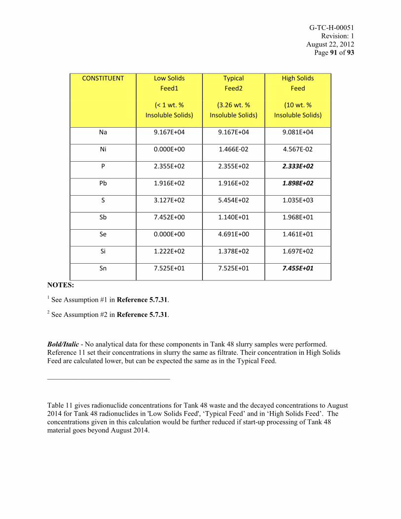
G-TC-H-00051Revision: 1
August 22, 2012Page 91 of 93
CONSTITUENT Low Solids
Feed1
Typical
Feed2
High Solids
Feed
(< 1 wt. %
Insoluble Solids)
(3.26 wt. %
Insoluble Solids)
(10 wt. %
Insoluble Solids)
Na 9.167E+04 9.167E+04 9.081E+04
Ni 0.000E+00 1.466E-02 4.567E-02
P 2.355E+02 2.355E+02 2.333E+02
Pb 1.916E+02 1.916E+02 1.898E+02
S 3.127E+02 5.454E+02 1.035E+03
Sb 7.452E+00 1.140E+01 1.968E+01
Se 0.000E+00 4.691E+00 1.461E+01
Si 1.222E+02 1.378E+02 1.697E+02
Sn 7.525E+01 7.525E+01 7.455E+01
NOTES:
1 See Assumption #1 in Reference 5.7.31.
2 See Assumption #2 in Reference 5.7.31.
Bold/Italic - No analytical data for these components in Tank 48 slurry samples were performed. Reference 11 set their concentrations in slurry the same as filtrate. Their concentration in High Solids Feed are calculated lower, but can be expected the same as in the Typical Feed.
__________________________________
Table 11 gives radionuclide concentrations for Tank 48 waste and the decayed concentrations to August 2014 for Tank 48 radionuclides in 'Low Solids Feed', ‘Typical Feed’ and in ‘High Solids Feed’. The concentrations given in this calculation would be further reduced if start-up processing of Tank 48 material goes beyond August 2014.

G-TC-H-00051Revision: 1
August 22, 2012Page 92 of 93
Table 11 - Tank 48 Feed Decayed Concentrations on Aug-14-2014
CONSTITUENT Unit Half-life, yr 1
Concentrations
@ Sample Report (Rev. 0) Date SRNL
Decayed Concentrations
@ Aug-14-2014
Low Solids
Feed2 Typical Feed3 High Solids FeedSample Report Date4
Low Solids
Feed1 Typical Feed2 High Solids
Feed
(< 1 wt. %
Insoluble Solids)
(3.26 wt. %
Insoluble Solids)
(10 wt. %
Insoluble Solids)
Low Solids
Feed2
(Filtrate)
Typical Feed3
(Slurry)
(< 1 wt. %
Insoluble Solids)
(3.26 wt. %
Insoluble Solids)
(10 wt. %
Insoluble
Solids)
Cs-137 Ci/gal 3.008E+01 6.332E-02 1.670E+00 5.068E+00 3/6/2005 9/17/2003 5.094E-02 1.299E+00 3.938E+00
Sr-90 Ci/gal 2.890E+01 5.583E-06 3.127E-04 9.623E-04 9/17/2003 9/17/2003 4.298E-06 2.407E-04 7.408E-04
Tc-99 Ci/gal 2.111E+05 1.796E-04 1.796E-04 1.779E-04 11/18/2005 11/18/2005 1.796E-04 1.796E-04 1.779E-04
Th-232 Ci/gal 1.400E+10 7.921E-12 7.921E-12 7.847E-12 11/18/2005 11/18/2005 7.921E-12 7.921E-12 7.847E-12
U-233 Ci/gal 1.592E+05 3.710E-07 3.908E-06 1.139E-05 3/6/2005 12/4/1995 3.710E-07 3.908E-06 1.139E-05
U-234 Ci/gal 2.455E+05 1.759E-06 1.281E-05 3.617E-05 3/6/2005 12/4/1995 1.759E-06 1.281E-05 3.617E-05
U-235 Ci/gal 7.040E+08 1.188E-09 8.550E-09 2.411E-08 3/6/2005 12/4/1995 1.188E-09 8.550E-09 2.411E-08
U-236 Ci/gal 2.342E+07 7.755E-09 3.573E-07 1.097E-06 3/6/2005 12/4/1995 7.755E-09 3.573E-07 1.097E-06
U-238 Ci/gal 4.468E+09 1.096E-09 8.377E-09 2.377E-08 3/6/2005 12/4/1995 1.096E-09 8.377E-09 2.377E-08
Np-237 Ci/gal 2.144E+06 5.299E-08 9.951E-07 2.987E-06 9/17/2003 12/4/1995 5.299E-08 9.951E-07 2.987E-06
Pu-238 Ci/gal 8.770E+01 3.406E-06 8.131E-03 2.532E-02 9/17/2003 12/4/1995 3.125E-06 7.014E-03 2.184E-02

G-TC-H-00051Revision: 1
August 22, 2012Page 93 of 93
CONSTITUENT Unit Half-life, yr 1
Concentrations
@ Sample Report (Rev. 0) Date SRNL
Decayed Concentrations
@ Aug-14-2014
Low Solids
Feed2 Typical Feed3 High Solids FeedSample Report Date4
Low Solids
Feed1 Typical Feed2 High Solids
Feed
(< 1 wt. %
Insoluble Solids)
(3.26 wt. %
Insoluble Solids)
(10 wt. %
Insoluble Solids)
Low Solids
Feed2
(Filtrate)
Typical Feed3
(Slurry)
(< 1 wt. %
Insoluble Solids)
(3.26 wt. %
Insoluble Solids)
(10 wt. %
Insoluble
Solids)
Pu-239 Ci/gal 2.411E+04 1.150E-05 1.960E-05 3.663E-05 3/6/2005 12/4/1995 1.150E-05 1.959E-05 3.660E-05
Pu-240 Ci/gal 6.561E+03 4.120E-07 8.907E-06 2.687E-05 9/17/2003 12/4/1995 4.115E-07 8.889E-06 2.682E-05
Pu-241 Ci/gal 1.429E+01 0.000E+00 7.298E-04 2.274E-03 12/4/1995 12/4/1995 0.000E+00 2.947E-04 9.181E-04
NOTES:
1 Radionuclide ‘Half-life’ values are taken from the National Nuclear Data Center (NNDC), Brookhaven National Laboratory Chart of the Nuclides website, for 'Half-life' values (website: http://www.nndc.bnl.gov/chart/).
2 See Assumption #1 in Reference 5.7.31.
3 See Assumption #2 in Reference 5.7.31.
4 See Assumption #6 in Reference 5.7.31.
5 Per Section 3.0 of Reference 5.7.31.
______________________________________________
Combustibility and Flammability
The tetraphenylborate solids, when dried, represent a combustibility hazard. When burned, the material produces a thick smoke with relative low releases rates for the contained radionuclides. However, the material dries extremely slowly and requires high-energy heat sources for a fire to initiate. Tank 241-948H materials have a hydrogen generation rate8 of 1.98E-07 ft3/hr/gal.
8
Waste Characterization System, ‘\\Wg17\wcs1.5prod\WCS_1.5[Formula 01]’


![ADVANCED GUN SYSTEM (AGS) BACKFIT - [email protected]: Home](https://static.fdocuments.net/doc/165x107/61fb61202e268c58cd5d7994/advanced-gun-system-ags-backfit-emailprotected-home.jpg)