TARGET FABRICATION AND CHARACTERIZATION DEVELOPMENT IN ... · Project Staff FY02 Target Fabrication...
56
QTYUIOP GA–A24421 TARGET FABRICATION AND CHARACTERIZATION DEVELOPMENT IN SUPPORT OF NRL LASER-PLASMA PROGRAM ANNUAL REPORT TO THE U.S. DEPARTMENT OF NAVY JANUARY 14, 2002 THROUGH MARCH 5, 2003 by PROJECT STAFF Work prepared under U.S. Department of Navy Naval Research Laboratory Contract No. N00173-02-C-6007 DATE PUBLISHED: AUGUST 2003
Transcript of TARGET FABRICATION AND CHARACTERIZATION DEVELOPMENT IN ... · Project Staff FY02 Target Fabrication...
QTYUIOP
GA–A24421
TARGET FABRICATION ANDCHARACTERIZATION DEVELOPMENT IN SUPPORT
OF NRL LASER-PLASMA PROGRAMANNUAL REPORT TO THE
U.S. DEPARTMENT OF NAVY
JANUARY 14, 2002 THROUGH MARCH 5, 2003
byPROJECT STAFF
Work prepared underU.S. Department of Navy
Naval Research LaboratoryContract No. N00173-02-C-6007
DATE PUBLISHED: AUGUST 2003

QTYUIOP
DISCLAIMER
This report was prepared as an account of work sponsored by an agency of the United StatesGovernment. Neither the United States Government nor any agency thereof, nor any of theiremployees, makes any warranty, express or implied, or assumes any legal liability orresponsibility for the accuracy, completeness, or usefulness of any information, apparatus,product, or process disclosed, or represents that its use would not infringe privately owned rights.Reference herein to any specific commercial product, process, or service by trade name,trademark, manufacturer, or otherwise, does not necessarily constitute or imply its endorsement,recommendation, or favoring by the United States Government or any agency thereof. The viewsand opinions of authors expressed herein do not necessarily state or reflect those of the UnitedStates Government or any agency thereof.
QTYUIOP
GA–A24421
TARGET FABRICATION ANDCHARACTERIZATION DEVELOPMENT IN SUPPORT
OF NRL LASER-PLASMA PROGRAMANNUAL REPORT TO THE
U.S. DEPARTMENT OF NAVY
JANUARY 14, 2002 THROUGH MARCH 5, 2003
byPROJECT STAFF
Work prepared underU.S. Department of Navy
Naval Research LaboratoryContract No. N00173-02-C-6007
GENERAL ATOMICS PROJECT 39083DATE PUBLISHED: AUGUST 2003
Project Staff FY02 Target Fabrication and Characterization Developmentin Support of NRL Laser-Plasma Program Annual Report
General Atomics Report GA–A24421 v
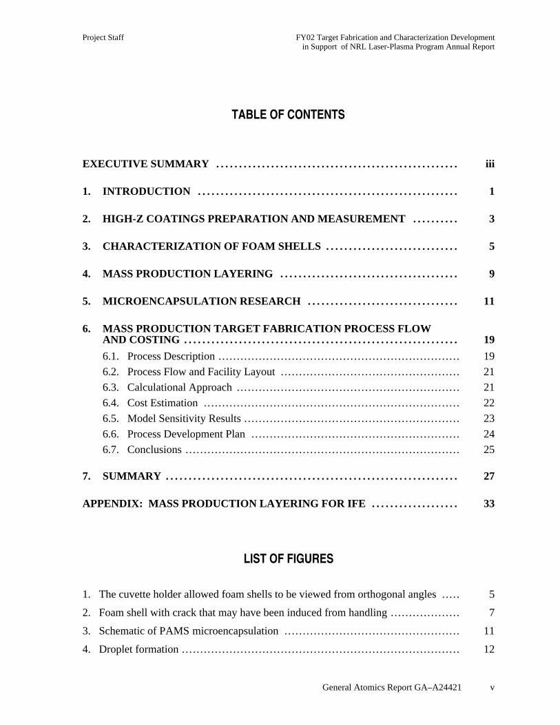
TABLE OF CONTENTS
EXECUTIVE SUMMARY . . . . . . . . . . . . . . . . . . . . . . . . . . . . . . . . . . . . . . . . . . . . . . . . . . . . . iii
1. INTRODUCTION . . . . . . . . . . . . . . . . . . . . . . . . . . . . . . . . . . . . . . . . . . . . . . . . . . . . . . . . . 1
2. HIGH-Z COATINGS PREPARATION AND MEASUREMENT . . . . . . . . . . 3
3. CHARACTERIZATION OF FOAM SHELLS . . . . . . . . . . . . . . . . . . . . . . . . . . . . . 5
4. MASS PRODUCTION LAYERING . . . . . . . . . . . . . . . . . . . . . . . . . . . . . . . . . . . . . . . 9
5. MICROENCAPSULATION RESEARCH . . . . . . . . . . . . . . . . . . . . . . . . . . . . . . . . . 11
6. MASS PRODUCTION TARGET FABRICATION PROCESS FLOWAND COSTING . . . . . . . . . . . . . . . . . . . . . . . . . . . . . . . . . . . . . . . . . . . . . . . . . . . . . . . . . . . . 19
6.1. Process Description .................................................................. 19
6.2. Process Flow and Facility Layout ................................................. 21
6.3. Calculational Approach ............................................................. 21
6.4. Cost Estimation ...................................................................... 22
6.5. Model Sensitivity Results ........................................................... 23
6.6. Process Development Plan ......................................................... 24
6.7. Conclusions ........................................................................... 25
7. SUMMARY . . . . . . . . . . . . . . . . . . . . . . . . . . . . . . . . . . . . . . . . . . . . . . . . . . . . . . . . . . . . . . . . 27
APPENDIX: MASS PRODUCTION LAYERING FOR IFE . . . . . . . . . . . . . . . . . . . 33
LIST OF FIGURES
1. The cuvette holder allowed foam shells to be viewed from orthogonal angles ..... 5
2. Foam shell with crack that may have been induced from handling ................... 7
3. Schematic of PAMS microencapsulation ................................................ 11
4. Droplet formation ............................................................................ 12
FY02 Target Fabrication and Characterization Development Project Staffin Support of NRL Laser-Plasma Program Annual Report
vi General Atomics Report GA–A24421
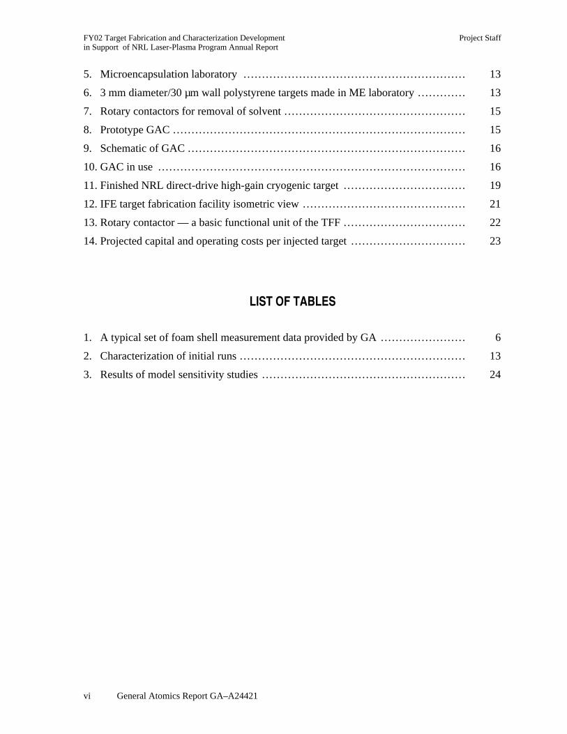
5. Microencapsulation laboratory ............................................................ 13
6. 3 mm diameter/30 µm wall polystyrene targets made in ME laboratory ............. 13
7. Rotary contactors for removal of solvent ................................................. 15
8. Prototype GAC ............................................................................... 15
9. Schematic of GAC ........................................................................... 16
10. GAC in use ................................................................................... 16
11. Finished NRL direct-drive high-gain cryogenic target ................................. 19
12. IFE target fabrication facility isometric view ............................................ 21
13. Rotary contactor — a basic functional unit of the TFF ................................. 22
14. Projected capital and operating costs per injected target ............................... 23
LIST OF TABLES
1. A typical set of foam shell measurement data provided by GA ....................... 6
2. Characterization of initial runs ............................................................. 13
3. Results of model sensitivity studies ....................................................... 24
Project Staff FY02 Target Fabrication and Characterization Developmentin Support of NRL Laser-Plasma Program Annual Report
General Atomics Report GA–A24421 iii
EXECUTIVE SUMMARY
Key issues for the future of Inertial Fusion Energy (IFE) include the ability tomanufacture large quantities of low-cost targets meeting precise specifications, and that areable to survive injection into a high-temperature IFE reaction chamber. The Naval ResearchLaboratory (NRL) has designed high-gain, direct-drive targets for both the IFE and theInertial Confinement Fusion (ICF) programs. The work this year has focused on developingthe scientific basis for fabricating, characterizing, and injecting high-gain, direct-drivetargets.
This report describes the work conducted this year for target fabrication andcharacterization. A companion report documents the work done for target injection andtracking. Target fabrication research and development tasks included (1) development ofhigh-Z overcoats for targets, (2) characterization of foam shells, (3) conducting micro-encapsulation research for target mass production, (4) experimental design of a cryogenicfluidized bed layering system, and (5) target mass production process flow and costing.
In support of these tasks, our major accomplishments included:
• Presented work and prepared publication for high atomic number target coatings,including gold and palladium.
• Characterized foam shells in index matching fluids using a newly developed opticalfixture that allows viewing from two orthogonal directions without moving the shells.
• Built and tested apparatus to produce shells by the microencapsulation process, andbuilt a prototype gas agitated contactor to test an improved method to cure the shells.
• Performed scoping studies and design calculations for an experimental cryogenicfluidized bed to be used for deuterium layering experiments.
• Prepared a process description for mass production of IFE targets with a preliminaryfacility layout and production cost estimates.
The target fabrication workscope this year has made significant progress in extending theknowledge base and developing a “credible pathway” for inertial fusion target fabrication.The result of these tasks is increased confidence in the overall feasibility of direct-driveinertial fusion energy.

Project Staff FY02 Target Fabrication and Characterization Developmentin Support of NRL Laser-Plasma Program Annual Report
General Atomics Report GA–A24421 1
1. INTRODUCTION
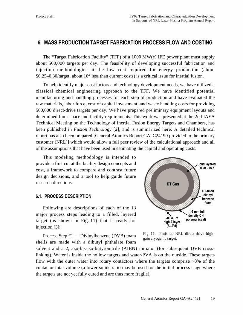
The realization of inertial fusion energy begins with the successful fabrication andcharacterization of high gain targets. The NRL direct-drive high-gain target consists of fourparts: a DT-filled low-density foam shell with a full-density polymer “seal coat” of 1 to5 µm, covered with a high-Z material (Au and/or Pd), a layer of solid DT fuel, and a corecontaining DT vapor. These targets must meet precise specifications and be mass-producedat low-cost for an inertial fusion energy plant to be feasible. These targets are filled with DTgas, lowered to cryogenic temperatures, and layered. The layering process makes use of thenaturally occurring energy from beta decay of DT (sometimes supplemented by external rf orinfrared energy) to heat the DT on the inner surface of the capsule. The inner temperature ofthe thicker portions of the layer gets warmer than the rest and ablates. This ablated DTcondenses on thinner parts of the layer. Over a period of hours, this leads to a very smoothand uniform DT layer.
Target fabrication research and development tasks included (1) development of high-Zovercoats for targets, (2) characterization of foam shells, (3) conducting micro-encapsulationresearch for target mass production, (4) experimental design of a cryogenic fluidized bedlayering system, and (5) target mass production process flow and costing. This reportdescribes work done by General Atomics in the past year in these areas to develop thescientific basis for low-cost mass-production of the NRL direct drive target.

Project Staff FY02 Target Fabrication and Characterization Developmentin Support of NRL Laser-Plasma Program Annual Report
General Atomics Report GA–A24421 3
2. HIGH-Z COATINGS PREPARATION AND MEASUREMENT
High atomic number (Z) coatings are desirable on targets for two reasons. High Zcoatings have been shown to reduce laser imprint on targets. These coatings are also highlyreflective, thereby reducing radiation heating of the cryogenic targets during injection into ahot power plant reaction chamber.
Two presentations on this topic were prepared and delivered at the 2nd IAEA TechnicalMeeting on the Technology of Inertial Fusion Energy Targets and Chambers. They were“Thickness and Uniformity Measurements of Thin Sputtered Gold Layers on ICF Capsules”by Annette Greenwood and “Palladium and Palladium Gold Alloys as High Z Coating forIFE Targets” by Elizabeth Stephens. A paper was also written and accepted for publication:“Optimizing High Z Coatings for IFE Shells,” Fusion Science and Technology (May 2003).These presentations and paper reported our investigations of gold and palladium for the high-Z target coatings, as summarized below.
X-ray fluorescence is used to measure high Z layer thickness on the shells. An x-raybeam is passed through the shell, which emits x-rays characteristic of the elements present. Adetector captures portions of the x-rays and the resulting peaks correspond to the amount ofthe element present. Rotating the shells, we found that the layer thickness was uniformwithin the experimental uncertainty of about 10%.
Gold has a higher reflectivity than palladium. A 300 Å gold layer has an integratedreflectivity of 96% at expected power plant temperatures. The integrated reflectivity of apalladium coating at expected power plant temperatures is approximately 80%.
However, palladium is more permeable to hydrogen than is gold. High permeability isimportant to reduce target filling time and tritium inventories. A 300 Å gold layer reducedthe rate at which deuterium permeates out of PAMS shell by a factor of 6. An 1100 Åpalladium layer caused only a slight reduction in shell permeability. Layers of gold andpalladium sputtered simultaneously on the shells still had very high permeability and gavereflectivity that is intermediate between the reflectivity of gold and palladium.
We performed tests to verify that the high permeation rates that were measured forhydrogen through the shells were due to catalysis rather than small cracks in the palladium orother effects. This was done by diffusing noble gases (first argon and later krypton) into theshells and performing x-ray fluorescence measurements. The measurements for argonconcentration were complicated by the overlap of argon and palladium emission lines.Additionally, measurements for krypton were also inconsistent, possibly because the shellsthat were used for this testing had been through excessive handling. The tests with kryptonwill be tried again with fresh shells.

Project Staff FY02 Target Fabrication and Characterization Developmentin Support of NRL Laser-Plasma Program Annual Report
General Atomics Report GA–A24421 5
3. CHARACTERIZATION OF FOAM SHELLS
We provided characterization of divinyl benzene foam shells supplied by Diana Schroenof Schafer Corp., through her IFE work at SNL. We devised a simple means of opticallycharacterizing these semi-opaque foam shells. This involves obtaining pictures of themagnified foam shells at two orthogonal angles using light passing through each shell thathighlights the edges of the inner and outer walls.
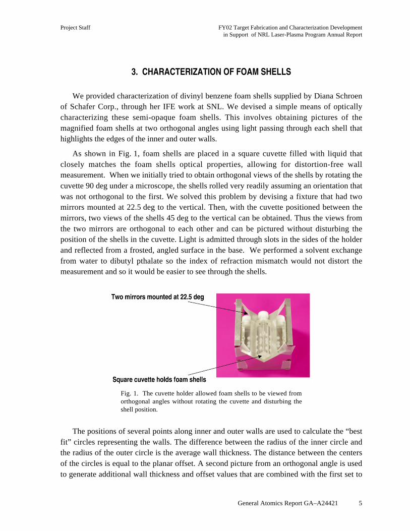
As shown in Fig. 1, foam shells are placed in a square cuvette filled with liquid thatclosely matches the foam shells optical properties, allowing for distortion-free wallmeasurement. When we initially tried to obtain orthogonal views of the shells by rotating thecuvette 90 deg under a microscope, the shells rolled very readily assuming an orientation thatwas not orthogonal to the first. We solved this problem by devising a fixture that had twomirrors mounted at 22.5 deg to the vertical. Then, with the cuvette positioned between themirrors, two views of the shells 45 deg to the vertical can be obtained. Thus the views fromthe two mirrors are orthogonal to each other and can be pictured without disturbing theposition of the shells in the cuvette. Light is admitted through slots in the sides of the holderand reflected from a frosted, angled surface in the base. We performed a solvent exchangefrom water to dibutyl pthalate so the index of refraction mismatch would not distort themeasurement and so it would be easier to see through the shells.
Fig. 1. The cuvette holder allowed foam shells to be viewed fromorthogonal angles without rotating the cuvette and disturbing theshell position.
The positions of several points along inner and outer walls are used to calculate the “bestfit” circles representing the walls. The difference between the radius of the inner circle andthe radius of the outer circle is the average wall thickness. The distance between the centersof the circles is equal to the planar offset. A second picture from an orthogonal angle is usedto generate additional wall thickness and offset values that are combined with the first set to
FY02 Target Fabrication and Characterization Development Project Staffin Support of NRL Laser-Plasma Program Annual Report
6 General Atomics Report GA–A24421
generate the average outer diameter, average wall thickness, and three-dimensional offsetvalues.
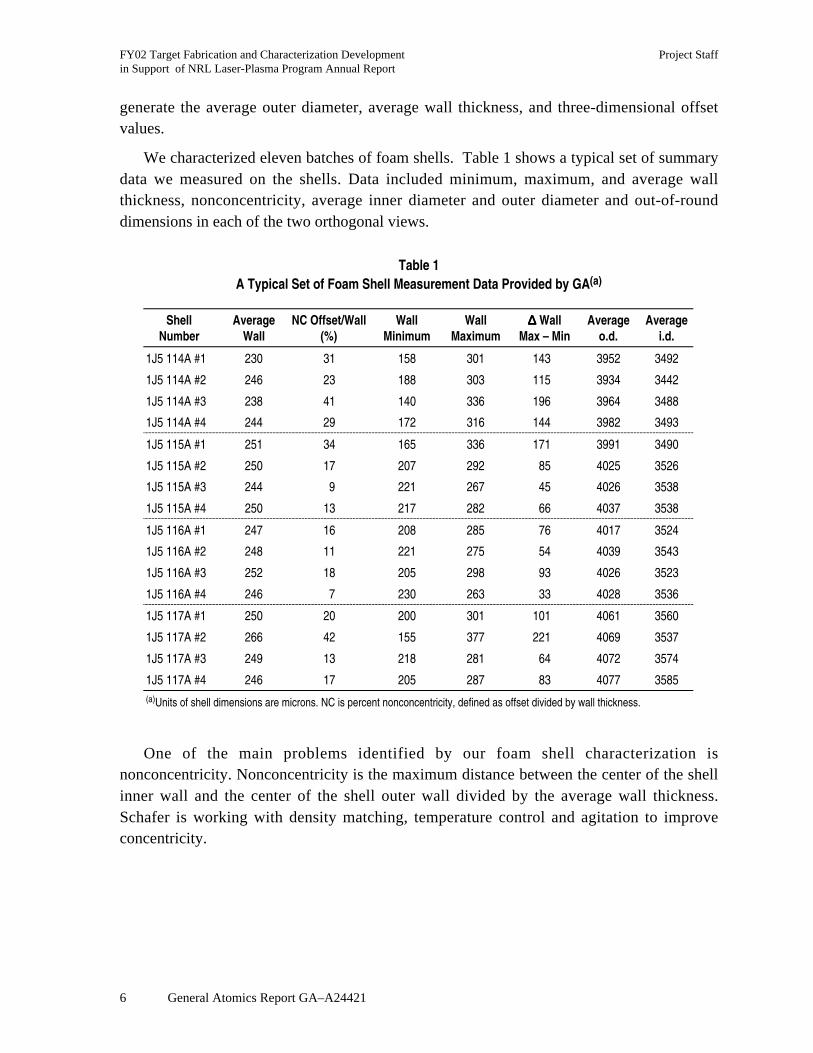
We characterized eleven batches of foam shells. Table 1 shows a typical set of summarydata we measured on the shells. Data included minimum, maximum, and average wallthickness, nonconcentricity, average inner diameter and outer diameter and out-of-rounddimensions in each of the two orthogonal views.
Table 1A Typical Set of Foam Shell Measurement Data Provided by GA(a)
ShellNumber
AverageWall
NC Offset/Wall(%)
WallMinimum
WallMaximum
∆∆∆∆ WallMax – Min
Averageo.d.
Averagei.d.
1J5 114A #1 230 31 158 301 143 3952 3492
1J5 114A #2 246 23 188 303 115 3934 3442
1J5 114A #3 238 41 140 336 196 3964 3488
1J5 114A #4 244 29 172 316 144 3982 3493
1J5 115A #1 251 34 165 336 171 3991 3490
1J5 115A #2 250 17 207 292 85 4025 3526
1J5 115A #3 244 9 221 267 45 4026 3538
1J5 115A #4 250 13 217 282 66 4037 3538
1J5 116A #1 247 16 208 285 76 4017 3524
1J5 116A #2 248 11 221 275 54 4039 3543
1J5 116A #3 252 18 205 298 93 4026 3523
1J5 116A #4 246 7 230 263 33 4028 3536
1J5 117A #1 250 20 200 301 101 4061 3560
1J5 117A #2 266 42 155 377 221 4069 3537
1J5 117A #3 249 13 218 281 64 4072 3574
1J5 117A #4 246 17 205 287 83 4077 3585(a)Units of shell dimensions are microns. NC is percent nonconcentricity, defined as offset divided by wall thickness.
One of the main problems identified by our foam shell characterization isnonconcentricity. Nonconcentricity is the maximum distance between the center of the shellinner wall and the center of the shell outer wall divided by the average wall thickness.Schafer is working with density matching, temperature control and agitation to improveconcentricity.

Project Staff FY02 Target Fabrication and Characterization Developmentin Support of NRL Laser-Plasma Program Annual Report
General Atomics Report GA–A24421 7
The shells are quite fragile and are easily cracked when handled. Figure 2 illustrates anexample of a cracked shell. About 25% of the shells were cracked after shipping to GA andnearly 95% were cracked after the solvent exchange process. To minimize the amount ofshell damage, it was ultimately decided to begin characterizing the shells onsite at SNL.
Fig. 2. Foam shell with crack that may have been induced from handling.

Project Staff FY02 Target Fabrication and Characterization Developmentin Support of NRL Laser-Plasma Program Annual Report
General Atomics Report GA–A24421 9
4. MASS PRODUCTION LAYERING
Demonstration of mass-production layering is a high priority for target fabrication. Ourstudies for mass production layering were reported at the April 2003 HAPL meeting. Thepresentation viewgraphs are included in the Appendix and are summarized here.
Mass production layering processes must be quite different than the layering sphereprocess that is currently used for direct-drive single target layering. One possibility is the falland strike technique that the Russians are investigating at Lebedev Physical Institute. Wesupport the fall and strike study as a potential backup,1 and will learn what we can from thisstudy, but we do not believe that we can rely on fall and strike as the only layering method.We are focusing our efforts on the fluidized bed approach.
Relatively simple equations have been used to estimate the time required for a target tocirculate through a fluidized bed. The circulation time depends on the gas velocity, density,viscosity, density and the particle density and diameter, and the height of particles in thefluidized bed. A typical example is given for a fluidized bed with a circulation time of 0.27 s;the temperature difference from top to bottom of the bed is only 0.054 K. This rapidcirculation and small temperature gradient is calculated to lead to only 3 mK temperaturechanges at the inner surface of the DT ice in one circulation time.
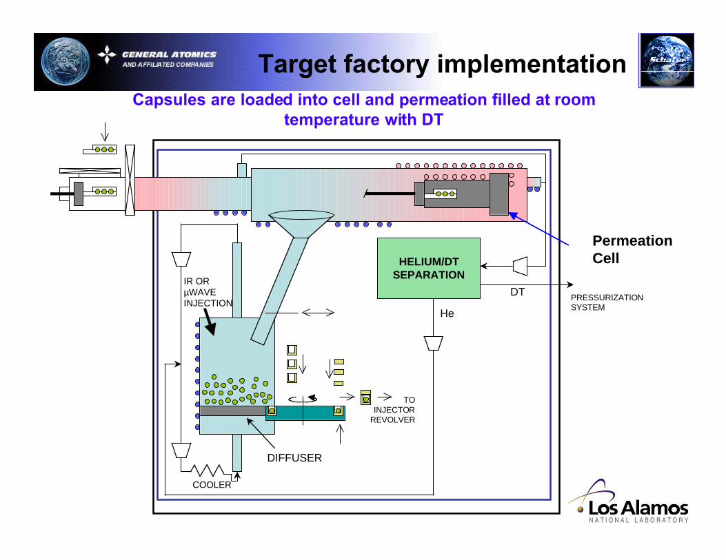
In a target factory, the capsules would be loaded into a cell and permeation filled at roomtemperature with DT. The capsules would then be cooled and dropped into a fluidized bed.The targets would be further cooled in the bed by a closed loop helium flow. The heliumcompressor would be inside the cryogenic environment to minimize the cooling powerrequirements. The gas flow for a fluidized bed with full sized targets is quite large, 1.8 g/s,and has large cooling requirements. We are evaluating the trade-offs with a scaled-downfluidized bed demonstration experiment.
1Letter of support was sent on January 13, 2003 to ISTC supporting the proposed 5-year study at LebedevPhysical Institute entitled “Development of a facility for producing the reactor-scaled cryogenic targets andtheir repeatable assembly with sabots.”

Project Staff FY02 Target Fabrication and Characterization Developmentin Support of NRL Laser-Plasma Program Annual Report
General Atomics Report GA–A24421 11
5. MICROENCAPSULATION RESEARCH
We performed research and development to examine scaleup opportunities, utilizingchemical engineering principals and apparatus, to understand the science behind massproduction of IFE targets. Specifically, we focused our efforts on producing 4.6 mm/250 µmwall polystyrene direct drive targets to produce a stock of targets for additional coating andlayering studies, and designed and tested apparatus for mass production of direct drivetargets. This information can be applied to the formation of indirect drive targets in futurestudies as well because many of the processes and apparatus are similar.
A presentation on this topic was prepared and delivered at the 2nd US/Japan Workshopon Target Fabrication, Injection, and Tracking, February 3–4, 2003, “MicroencapsulationStudies for Mass Production of IFE Targets” by Brian Vermillion. This presentation reportedour investigation into understanding the science of producing IFE targets as summarizedbelow.
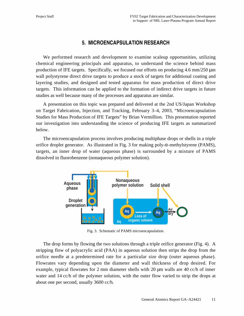
The microencapsulation process involves producing multiphase drops or shells in a tripleorifice droplet generator. As illustrated in Fig. 3 for making poly-α-methylstyrene (PAMS),targets, an inner drop of water (aqueous phase) is surrounded by a mixture of PAMSdissolved in fluorobenzene (nonaqueous polymer solution).
aq
Air dry
AqAq Loss oforganic solvent
Aqueousphase
Dropletgeneration
Nonaqueouspolymer solution Solid shell
Aq
Aq
Fig. 3. Schematic of PAMS microencapsulation.
The drop forms by flowing the two solutions through a triple orifice generator (Fig. 4). Astripping flow of polyacrylic acid (PAA) in aqueous solution then strips the drop from theorifice needle at a predetermined rate for a particular size drop (outer aqueous phase).Flowrates vary depending upon the diameter and wall thickness of drop desired. Forexample, typical flowrates for 2 mm diameter shells with 20 µm walls are 40 cc/h of innerwater and 14 cc/h of the polymer solution, with the outer flow varied to strip the drops atabout one per second, usually 3600 cc/h.

FY02 Target Fabrication and Characterization Development Project Staffin Support of NRL Laser-Plasma Program Annual Report
12 General Atomics Report GA–A24421
Fig. 4. Droplet formation.
Once the desired quantity is produced, the collected drops, or shells, are hardened byremoval of the fluorobenzene solvent from the nonaqueous polymer solution in rotaryevaporator containers warmed in water baths. Once the shells are solid, they undergo severalwashes to remove particulate contamination and debris from the shell surface. At this point,ethanol extraction of the water inside the shell is performed. The shells are then placed insidea vacuum oven at 25°C for approximately two weeks to completely dry the shells.
The triple orifice microencapsulation process is deceptively simple with few processvariables to manipulate. However, small changes in these variables can cause large andsometimes unanticipated changes in final shell characteristics. For example, if it is desired toshorten the time it takes to remove fluorobenzene solvent from the hardening shells, onecould increase the water bath temperature. However, this leads to significant changes in thesolubility of the polymer solution in the aqueous phase increasing surface roughness, densitychanges in each phase leading to density mismatch, viscosity changes of the solutionsaffecting agitation during hardening, and interfacial surface tension changes affecting shellconcentricity. Thus, one process variable change (water bath temperature) can lead tosignificant alterations in final shell characteristics.
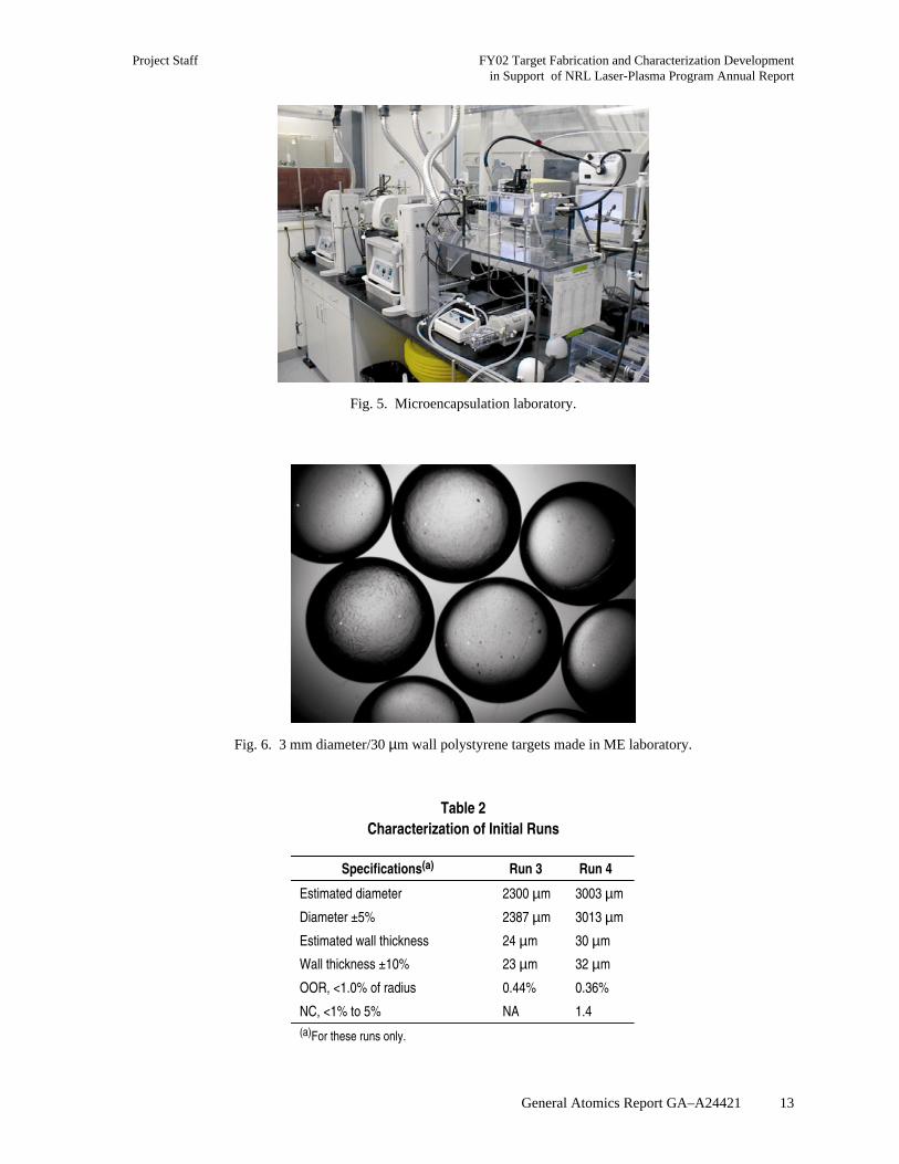
The IFE Microencapsulation Laboratory is up and operational (Fig. 5) with initialshakedown and experimental runs complete. Figure 6 shows 3 mm shells from an initial testrun. In Table 2, simplified characterization results are available for review of two initialruns.
Project Staff FY02 Target Fabrication and Characterization Developmentin Support of NRL Laser-Plasma Program Annual Report
General Atomics Report GA–A24421 13
Fig. 5. Microencapsulation laboratory.
Fig. 6. 3 mm diameter/30 µm wall polystyrene targets made in ME laboratory.
Table 2Characterization of Initial Runs
Specifications(a) Run 3 Run 4
Estimated diameter 2300 µm 3003 µm
Diameter ±5% 2387 µm 3013 µm
Estimated wall thickness 24 µm 30 µm
Wall thickness ±10% 23 µm 32 µm
OOR, <1.0% of radius 0.44% 0.36%
NC, <1% to 5% NA 1.4(a)For these runs only.
FY02 Target Fabrication and Characterization Development Project Staffin Support of NRL Laser-Plasma Program Annual Report
14 General Atomics Report GA–A24421
Mass production of IFE targets differs from the aforementioned lab scale process insignificant ways, as our goal is to form at least 500,000 targets per day in what will mostlikely be a continuous process. All aspects and assumptions of the process require review toidentify which areas need to be altered. The first such arena to explore are the liquid ratiosused in the laboratory scale process. Defined as volume of solution plus targets per thevolume of targets, the lab scale ratio is 200 to 1, while production scale will assume a ratio of10 to 1. Even with this lower ratio, up to 3,000 L of aqueous phase fluid will be required per100,000 unit run. Therefore, we have identified the need for a recycle stream to beimplemented in the droplet generation process, including a way to remove contaminants fromthe recycle stream.
Additionally, a parametric study needs to be undertaken to determine the flowratesrequired for larger IFE targets. While larger diameter targets have been successfully formedin the past (5 mm), they were formed with a thin wall, ~1% of diameter. The flow parametersfor thicker walled targets can be theoretically determined, but will have to be confirmed inthe laboratory since a different flow regime than is currently used will be required.Specifically, the ratio of the inner aqueous flow to nonaqueous polymer flow is generally 2.8to 1 for smaller targets (3 mm targets), but will have to altered to 1 to 2.3 for larger4.6 mm/250 µm wall targets. The effect this will have within the droplet generator needs tobe determined and will require a redesign and modification to the apparatus itself for largerdiameter targets.
Another aspect to explore is the optimization of the cure times for solvent removal fromthe nonaqueous polymer solution. Unfortunately, one cannot simply increase the rate ofsolvent removal, as is explained below. Surface defects are believed controlled by theMarangoni Effect [1], represented by the equation:
M
ddc
C L
D=
× ×
×
γ
η
∆ ,
where (dγ/dc) is the change of surface tension with concentration, ∆C is the concentrationgradient perpendicular to the surface, L is wall thickness, η is the polymer viscosity, and Dis the diffusivity of fluorobenzene within the polymer solution. If the Marangoni number istoo large, concentration cells form in the wall of the shell, leading to uneven surfaces on thetargets. In order to control these defects, we have in the past decreased both the surfacetension and concentration gradient to lower the Marangoni number. However, in the case oftargets with thicker walls (L = 250 µm), we are once again increasing the Marangoni number.But if we simply reduce the same parameters, surface tension and concentration gradient,then curing time is greatly extended.
Project Staff FY02 Target Fabrication and Characterization Developmentin Support of NRL Laser-Plasma Program Annual Report
General Atomics Report GA–A24421 15
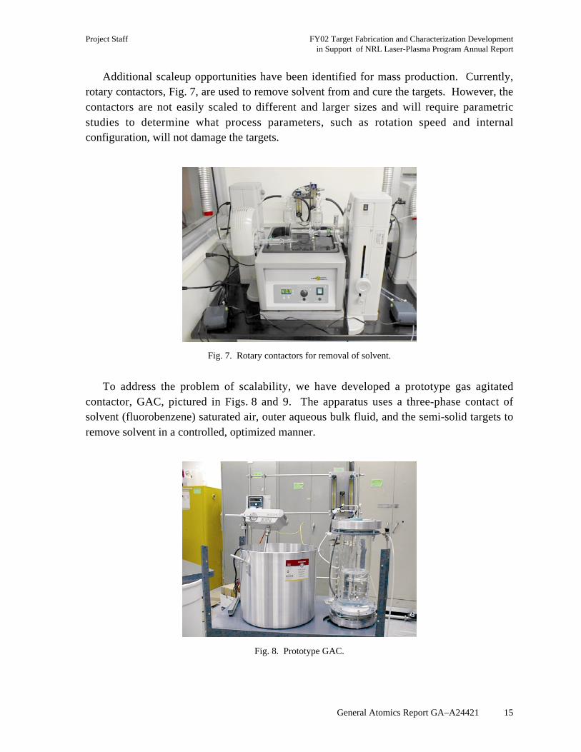
Additional scaleup opportunities have been identified for mass production. Currently,rotary contactors, Fig. 7, are used to remove solvent from and cure the targets. However, thecontactors are not easily scaled to different and larger sizes and will require parametricstudies to determine what process parameters, such as rotation speed and internalconfiguration, will not damage the targets.
Fig. 7. Rotary contactors for removal of solvent.
To address the problem of scalability, we have developed a prototype gas agitatedcontactor, GAC, pictured in Figs. 8 and 9. The apparatus uses a three-phase contact ofsolvent (fluorobenzene) saturated air, outer aqueous bulk fluid, and the semi-solid targets toremove solvent in a controlled, optimized manner.
Fig. 8. Prototype GAC.

FY02 Target Fabrication and Characterization Development Project Staffin Support of NRL Laser-Plasma Program Annual Report
16 General Atomics Report GA–A24421
Fig. 9. Schematic of GAC.
The GAC could possibly replace the rotary contactors in future mass productionscenarios. The design is eminently scaleable in the x-y direction once away from walleffects, without having to identify new process parameters by repeating time consumingparametric studies. An added benefit is that the design is easily adaptable to a continuousprocess, ideal for a large facility in the future. Functional attributes include using acontrolled mixture of air and fluorobenzene bubbles to remove fluorobenzene from thesystem and gently agitate the shells as pictured in Fig. 10. This apparatus can also be usedfor subsequent washings and water/ethanol extractions without exposing the targets tocontamination or the stress of being moved from container to container as is currently done.The design and fabrication is complete with test runs under way as pictured in Fig. 10.
Fig. 10. GAC in use.
Project Staff FY02 Target Fabrication and Characterization Developmentin Support of NRL Laser-Plasma Program Annual Report
General Atomics Report GA–A24421 17
The GAC will require foam minimization in order to be fully functional. We haveidentified that while the 0.05 wt% PAA aqueous stripping solution does not foam, the0.3 wt% to 3.0 wt% polyvinyl alcohol (PVA) aqueous solutions used to clean debris off theshells do foam. Therefore, a new washing solution with dual roles will have to be identifiedwith the ability to wash PAA off targets without foaming and that can be utilized in acontinuous process without excessive cost. Several solutions have been identified for testing:DI water, isopropanol, ethylene glycol, sodium hydroxide, and acetic acid.
Another area identified for process improvement is the droplet generator apparatuscurrently used for making the targets. A handmade glass needle is employed in the system.Several shapes of this needle are in use in different generators with each one requiringdifferent flowrates to achieve a shell with similar characteristics. This is not conducive tomass production, as it would be expensive and time-consuming to identify and reestablishflowrates every time a fragile glass needle requires replacement. Therefore, we have begun aredesign of this particular element of the droplet generator via a metal needle replacement.This needle will be self-centering as well as made of metal in order to have a consistentdesign to refer back to in case the part needs to be replaced. It is anticipated that designswith slight variations will need to be tested to ensure adequate operation, but once identified,will provide a vast improvement in repeatability and consistency.
Near term work goals for microencapsulation research and development include thefollowing: identify and confirm experimentally the required flowrates for larger diametertargets, examine alternative washing solutions for use in the GAC, and optimization ofsolvent removal rates within the new GAC apparatus. Additionally, longer-term researchwill focus on adding process control to the microencapsulation process in order to bettercontrol and increase the yield of acceptable targets. This will most likely entail opticalimaging systems to examine targets that have not yet been cured in real time, adding a pulsesystem to control target formation to speed up generation and reduce debris in the stream, aswell as exploring forced convection while the shells are drying. A current idea is to includeforced convection with dry nitrogen, cycled with applications of vacuum, to draw out theremaining ethanol from within the target interior.

Project Staff FY02 Target Fabrication and Characterization Developmentin Support of NRL Laser-Plasma Program Annual Report
General Atomics Report GA–A24421 19
6. MASS PRODUCTION TARGET FABRICATION PROCESS FLOW AND COSTING
The “Target Fabrication Facility” (TFF) of a 1000 MW(e) IFE power plant must supplyabout 500,000 targets per day. The feasibility of developing successful fabrication andinjection methodologies at the low cost required for energy production (about$0.25–0.30/target, about 104 less than current costs) is a critical issue for inertial fusion.
To help identify major cost factors and technology development needs, we have utilized aclassical chemical engineering approach to the TFF. We have identified potentialmanufacturing and handling processes for each step of production and have evaluated theraw materials, labor force, cost of capital investment, and waste handling costs for providing500,000 direct-drive targets per day. We have prepared preliminary equipment layouts anddetermined floor space and facility requirements. This work was presented at the 2nd IAEATechnical Meeting on the Technology of Inertial Fusion Energy Targets and Chambers, hasbeen published in Fusion Technology [2], and is summarized here. A detailed technicalreport has also been prepared [General Atomics Report GA–C24190 provided to the primarycustomer (NRL)] which would allow a full peer review of the calculational approach and allof the assumptions that have been used in estimating the capital and operating costs.
This modeling methodology is intended toprovide a first cut at the facility design concepts andcost, a framework to compare and contrast futuredesign decisions, and a tool to help guide futureresearch directions.
6.1. PROCESS DESCRIPTION
Following are descriptions of each of the 13major process steps leading to a filled, layeredtarget (as shown in Fig. 11) that is ready forinjection [3]:
Process Step #1 — Divinylbenzene (DVB) foamshells are made with a dibutyl phthalate foam
Fig. 11. Finished NRL direct-drive high-gain cryogenic target.
solvent and a 2, azo-bis-iso-butyronitrile (AIBN) initiator (for subsequent DVB cross-linking). Water is inside the hollow targets and water/PVA is on the outside. These targetsflow with the outer water into rotary contactors where the targets comprise ~8% of thecontactor total volume (a lower solids ratio may be used for the initial process stage wherethe targets are not yet fully cured and are thus more fragile).

FY02 Target Fabrication and Characterization Development Project Staffin Support of NRL Laser-Plasma Program Annual Report
20 General Atomics Report GA–A24421
Process Step #2 — The freshly formed DVB targets are gently stirred by the rotation ofthe contactor as the foam partially cross-links at ambient temperatures.
Process Step #3 — The partially cross-linked targets are heated to 85°C to more fullypolymerize and cross-link the DVB foam.
Process Step #4 — Isopropanol is sufficiently miscible in both water and oil(parachlorotoluene) to facilitate the transition from inner water (step #1–3) to inner oil(step #5).
Process Step #5 — Oil (parachlorotoluene) is transferred into the targets to provide amedium for Monomer A (isophthaloyl dichloride) to subsequently be dissolved into (instep #6).
Process Step #6 — Monomer A is dissolved into the oil inside of the targets.
Process Step #7 — Water/surfactant replaces the oil outside of the targets, keeps themfrom sticking together, and provides an aqueous medium for Monomer B (poly 4-vinylphenol) to be dissolved in Step #8.
Process Step #8 — Monomer B is added to the water/surfactant to initiate the formationof the 1–5 µm thick seal coat via polymerization of Monomers A and B at the oil/waterinterface on the target surface.
Process Step #9 — Isopropanol is sufficiently miscible in both oil (parachlorotoluene)and CO2 to facilitate the transition from inner oil/outer water (step #8) to inner/outer CO2
(step #10).
Process Step #10 — Liquid subcritical CO2 (20°C–800 psig) replaces the inner IPA bycountercurrent stagewise dilution contacting. The resulting liquid-CO2 filled targets areheated beyond the CO2 critical point (31°C–1070 psig) to reduce surface tension to zero andthus prevent target stress fracturing from depressurization forces during subsequent ventingof the supercritical CO2. This results in dry targets with only ambient pressure gaseous CO2
inside/outside, ready for the high-Z coating in step #11.
Process Step #11 — A thin (~0.03 µm) gold and/or palladium coating is added to theouter surface of the dried targets by a batch sputtering process (i.e., physical vapordeposition) performed in a vacuum (which removes the gaseous CO2 remaining in the targetfrom step #10).
Process Step #12 — DT is loaded into the targets by diffusion at high pressures (at roomtemperature or above) followed by condensation at cryogenic temperatures (≤20 K) to lowerthe internal pressure in the targets to prevent target rupturing as the external pressure isreduced.
Process Step #13 — DT-filled targets are maintained at a temperature slightly below thetriple point while they are gently fluidized with gaseous helium (to maintain a time-averaged
Project Staff FY02 Target Fabrication and Characterization Developmentin Support of NRL Laser-Plasma Program Annual Report
General Atomics Report GA–A24421 21
highly isothermal temperature profile on the entire surface of the sphere) and exposed to aheating beam that will result in preferential sublimation at thicker areas and eventually yielda uniform DT layer.
6.2. PROCESS FLOW AND FACILITY LAYOUT
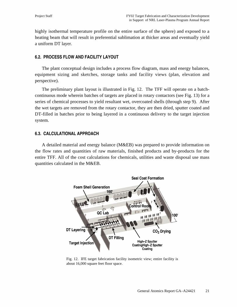
The plant conceptual design includes a process flow diagram, mass and energy balances,equipment sizing and sketches, storage tanks and facility views (plan, elevation andperspective).
The preliminary plant layout is illustrated in Fig. 12. The TFF will operate on a batch-continuous mode wherein batches of targets are placed in rotary contactors (see Fig. 13) for aseries of chemical processes to yield resultant wet, overcoated shells (through step 9). Afterthe wet targets are removed from the rotary contactor, they are then dried, sputter coated andDT-filled in batches prior to being layered in a continuous delivery to the target injectionsystem.
6.3. CALCULATIONAL APPROACH
A detailed material and energy balance (M&EB) was prepared to provide information onthe flow rates and quantities of raw materials, finished products and by-products for theentire TFF. All of the cost calculations for chemicals, utilities and waste disposal use massquantities calculated in the M&EB.
Fig. 12. IFE target fabrication facility isometric view; entire facility isabout 16,000 square feet floor space.

FY02 Target Fabrication and Characterization Development Project Staffin Support of NRL Laser-Plasma Program Annual Report
22 General Atomics Report GA–A24421
Fig. 13. Rotary contactor — a basic functional unit of the TFF.
Statistical sampling of target batches will be performed at every process step to avoidunnecessary further processing of off-spec targets. Finished dried shells with high-Z coatingswill be sampled (100% QA in a final “flow-through” step) and stockpiled (potentially at acentral facility serving multiple power plants) to assure a reliable supply backlog of severaldays of on-spec empty targets. The empty targets need only then be DT-filled and cryo-layered prior to injection. Overall target QA rejection rates are arbitrarily assumed in thiswork to be 25% with sensitivity studies covering a wider range of 5% to 75% reject rates.(The 25% reject rate is only a conservative assumption for calculational purposes; reject ratesfor a mature plant are expected to be much less than 25%.)
6.4. COST ESTIMATION
The cost estimate includes both capital and operating costs. Capital costs are brokendown into purchased equipment, engineering/contingency, buildings/auxiliaries andpiping/electrical/instrumentation. Operating costs are broken down into operating staff,chemicals, maintenance, utilities and waste disposal. Sampling and inspection equipment andstaffing costs are included at all stages of target preparation. Where appropriate, initialdiscussions are underway with vendors of commercial equipment that may be used in thefacility. In other cases, the costs of new or novel equipment have been estimated usingengineering judgment followed by peer feedback from researchers skilled in these areas ofexpertise.
Project Staff FY02 Target Fabrication and Characterization Developmentin Support of NRL Laser-Plasma Program Annual Report
General Atomics Report GA–A24421 23
A generous operating staff has been allocated to the operations. There are 12 staffworking a normal “5/8 day shift”2 and an additional 28 production personnel present per shiftto operate the facility. The model assumes 5-shift operation to cover 24/7 operations alongwith vacations, holidays, etc. Job categories include operators, technicians, health physicists,QA/QC specialists, supervisors, engineers and clerks.
Maintenance expenses are calculated using a factored percentage (6% per year) ofinstalled capital costs. Utilities, waste disposal and chemical costs were calculated usingvendor-supplied prices coupled with M&EB mass flow requirements.
6.5. MODEL SENSITIVITY RESULTS
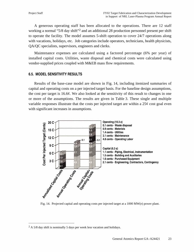
Results of the base-case model are shown in Fig. 14, including itemized summaries ofcapital and operating costs on a per injected target basis. For the baseline design assumptions,the cost per target is 16.6¢. We also looked at the sensitivity of this result to changes in oneor more of the assumptions. The results are given in Table 3. These single and multiplevariable responses illustrate that the costs per injected target are within a 25¢ cost goal evenwith significant increases in assumptions.
Fig. 14. Projected capital and operating costs per injected target at a 1000 MW(e) power plant.
2 A 5/8 day shift is nominally 5 days per week less vacation and holidays.
FY02 Target Fabrication and Characterization Development Project Staffin Support of NRL Laser-Plasma Program Annual Report
24 General Atomics Report GA–A24421
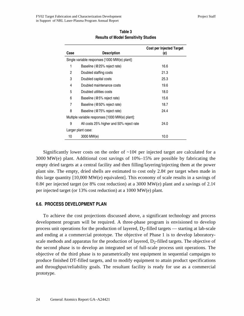
Table 3Results of Model Sensitivity Studies
Case DescriptionCost per Injected Target
(¢)
Single variable responses [1000 MW(e) plant]:
1 Baseline (@25% reject rate) 16.6
2 Doubled staffing costs 21.3
3 Doubled capital costs 25.3
4 Doubled maintenance costs 19.6
5 Doubled utilities costs 18.0
6 Baseline (@5% reject rate) 15.6
7 Baseline (@50% reject rate) 18.7
8 Baseline (@75% reject rate) 24.4
Multiple variable responses [1000 MW(e) plant]:
9 All costs 25% higher and 50% reject rate 24.0
Larger plant case:
10 3000 MW(e) 10.0
Significantly lower costs on the order of ~10¢ per injected target are calculated for a3000 MW(e) plant. Additional cost savings of 10%–15% are possible by fabricating theempty dried targets at a central facility and then filling/layering/injecting them at the powerplant site. The empty, dried shells are estimated to cost only 2.8¢ per target when made inthis large quantity [10,000 MW(e) equivalent]. This economy of scale results in a savings of0.8¢ per injected target (or 8% cost reduction) at a 3000 MW(e) plant and a savings of 2.1¢per injected target (or 13% cost reduction) at a 1000 MW(e) plant.
6.6. PROCESS DEVELOPMENT PLAN
To achieve the cost projections discussed above, a significant technology and processdevelopment program will be required. A three-phase program is envisioned to developprocess unit operations for the production of layered, D2-filled targets — starting at lab-scaleand ending at a commercial prototype. The objective of Phase 1 is to develop laboratory-scale methods and apparatus for the production of layered, D2-filled targets. The objective ofthe second phase is to develop an integrated set of full-scale process unit operations. Theobjective of the third phase is to parametrically test equipment in sequential campaigns toproduce finished DT-filled targets, and to modify equipment to attain product specificationsand throughput/reliability goals. The resultant facility is ready for use as a commercialprototype.
Project Staff FY02 Target Fabrication and Characterization Developmentin Support of NRL Laser-Plasma Program Annual Report
General Atomics Report GA–A24421 25
6.7. CONCLUSIONS
A facility flowsheet, plant layout and cost model have been formulated using classicalchemical engineering principles to scaleup current laboratory fabrication methods.
The cost of injected targets is estimated to be ~17¢ each for a 1000 MW(e) power plant.For the baseline assumptions, the annualized capital costs represent roughly 40% of the costper target while annual operating costs are ~60% [for large power plants in the1000–3000 MW(e) range]. Economies of scale (in terms of capital equipment, staffing andoverhead) favor larger plants. Capital and operating costs both increase less rapidly thanproduction rate increases, which leads to lower unit costs [from 16.6¢ per injected target at1000 MW(e) to 10.0¢ per injected target at 3000 MW(e)].
These projections assume that a significant process R&D program (summarized herein) issuccessfully completed.


Project Staff FY02 Target Fabrication and Characterization Developmentin Support of NRL Laser-Plasma Program Annual Report
General Atomics Report GA–A24421 27
7. SUMMARY
Target fabrication work at GA is focused on five major areas that are briefly summarizedin the following paragraphs.
We prepared presentations and publications for our study of high Z coatings on IFEtargets. Gold has higher reflectivity (which is beneficial to reduce in-chamber target heating)than palladium. However, palladium has higher permeability to hydrogen to allow more rapidtarget filling and reduced tritium inventories in the target fabrication plant. A combination ofthe two metals may be an optimum coating.
We characterized foam shells produced by Schafer Inc. We used index matching fluidand a new fixture that we developed to observe the targets from two orthogonal directions.Measurement data were provided for minimum, maximum, and average wall thickness,nonconcentricity, average inner diameter, outer diameter, and out-of-round dimensions.Methods to improve the identified nonconcentricity are being worked on by Schafer.
We performed scoping studies and calculations for a cryogenic fluidized bed targetlayering system. Based on this work, a fluidized bed layering experiment is being designed todemonstrate deuterium layering using this method.
We produced 3-mm diameter polystyrene shells using a triple orifice micro-encapsulationtechnique. A gas agitated contactor was designed and implemented to potentially improveshell curing time and quality. Several scaleup opportunities were identified and preliminarywork begun.
We proposed a process and facilities for mass producing direct drive IFE targets. Abaseline cost estimate of 16.6 cents per injected target was obtained in this study.


Project Staff FY02 Target Fabrication and Characterization Developmentin Support of NRL Laser-Plasma Program Annual Report
General Atomics Report GA–A24421 29
ACKNOWLEDGMENTS
This report was prepared for the U.S. Department of Navy, Naval Research LaboratoryContract No. N00173-02-C-6007.

Project Staff FY02 Target Fabrication and Characterization Developmentin Support of NRL Laser-Plasma Program Annual Report
General Atomics Report GA–A24421 31
REFERENCES
[1] B.W. McQuillan, M. Takagi, “Removal of Mode 10 Surface Ripples in ICF PAMSShells,” Proc. 14th Target Fabrication Specialists Meeting, West Point, New York, 2001,to be published in Fusion Technology; General Atomics Report GA–A23747 (2002).
[2] W.S. Rickman, D.T. Goodin, “Cost Modeling for Fabrication of Direct Drive IFETargets,” Fusion Science and Technology (May 2003).
[3] J. Streit, D. Schroen, “Development of Divinylbenzene Foam Shells for Use as InertialFusion Energy Reactor Targets,” Fusion Science and Technology (May 2003).


Project Staff FY02 Target Fabrication and Characterization Developmentin Support of NRL Laser-Plasma Program Annual Report
General Atomics Report GA–A24421 33
APPENDIXMASS PRODUCTION LAYERING FOR IFE
Mass Production Layering forInertial Fusion Energy
presented byNeil Alexander
HAPL Project ReviewAlbuquerque, New Mexico
April 9, 2003
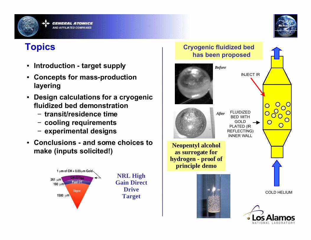
Topics
NRL HighGain Direct
DriveTarget
• Introduction - target supply
• Concepts for mass-productionlayering
• Design calculations for a cryogenicfluidized bed demonstration− transit/residence time− cooling requirements− experimental designs
• Conclusions - and some choices tomake (inputs solicited!)
Neopentyl alcoholas surrogate for
hydrogen - proof ofprinciple demo
COLD HELIUM
FLUIDIZEDBED WITH
GOLDPLATED (IR
REFLECTING)INNER WALL
INJECT IR
Cryogenic fluidized bedhas been proposed
Before
After
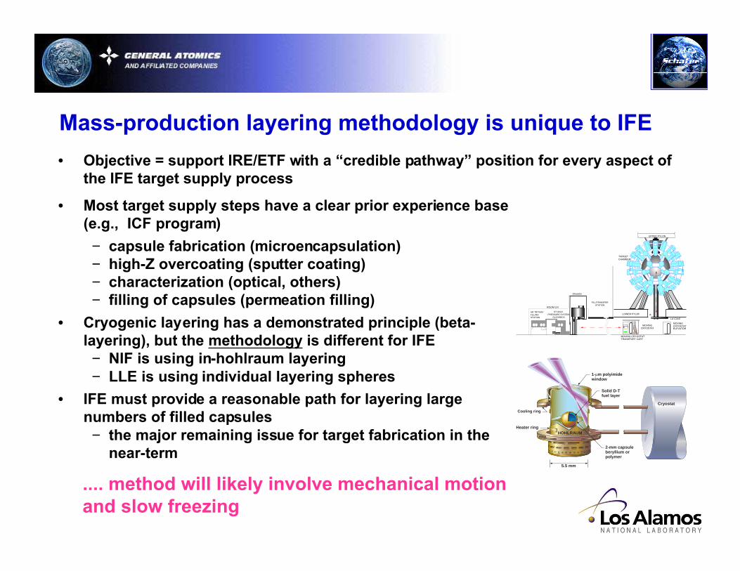
• Most target supply steps have a clear prior experience base(e.g., ICF program)
− capsule fabrication (microencapsulation)− high-Z overcoating (sputter coating)− characterization (optical, others)− filling of capsules (permeation filling)
• Cryogenic layering has a demonstrated principle (beta-layering), but the methodology is different for IFE− NIF is using in-hohlraum layering− LLE is using individual layering spheres
• IFE must provide a reasonable path for layering largenumbers of filled capsules− the major remaining issue for target fabrication in the
near-term
Mass-production layering methodology is unique to IFE
MOVING CRYOSTAT
LA CAVE
MOVING CRYOSTAT TRANSPORT CART
ROOM 157
UR TRITIUM FILLING STATION
DT HIGH PRESSURE SYSTEM
GLOVEBOX
MOVING CRYOSTAT ELEVATOR
LOWER PYLON
UPPER PYLON
TARGET CHAMBER
FILL/TRANSFER STATION
Glovebox
Cooling ring
Heater ring
5.5 mm
Heat-flow �coupler
HOHLRAUM
Cryostat
Cooling ring
2-mm capsule �beryllium or �polymer
Solid D-T �fuel layer ��
1-µm polyimide �window
.... method will likely involve mechanical motionand slow freezing
• Objective = support IRE/ETF with a “credible pathway” position for every aspect ofthe IFE target supply process
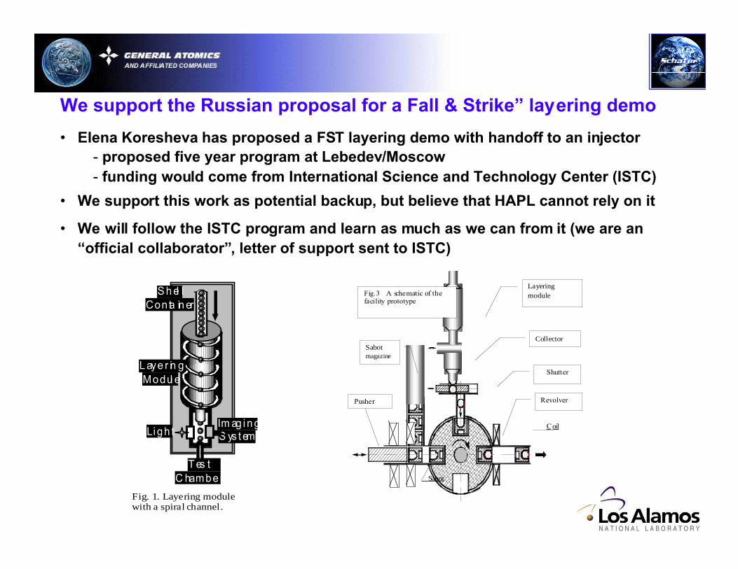
We support the Russian proposal for a Fall & Strike” layering demo
Im ag i n gS ys t em Ligh t
L aye r in gModul e
S h el lConta in er
T es tC hamber
Fig. 1. Layering modulewith a spiral channel.
• Elena Koresheva has proposed a FST layering demo with handoff to an injector- proposed five year program at Lebedev/Moscow- funding would come from International Science and Technology Center (ISTC)
• We support this work as potential backup, but believe that HAPL cannot rely on it
• We will follow the ISTC program and learn as much as we can from it (we are an“official collaborator”, letter of support sent to ISTC)
Layeringmodule
Collector
Shutter
Sabotmagazine
RevolverPusher
Coil
Fig.3 A schematic of thefacility prototype
Sabot
tH
U UU U
U
pmf
mfmf
b
=−( ) −
−
0 6 1.
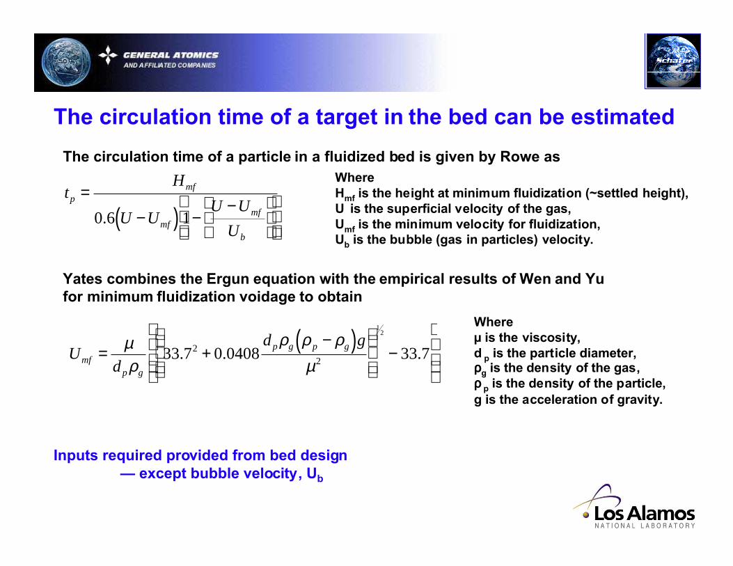
The circulation time of a particle in a fluidized bed is given by Rowe asWhereHmf is the height at minimum fluidization (~settled height),U is the superficial velocity of the gas,Umf is the minimum velocity for fluidization,Ub is the bubble (gas in particles) velocity.
Yates combines the Ergun equation with the empirical results of Wen and Yufor minimum fluidization voidage to obtain
Ud
d gmf
p g
p g p g= +−( )
−
µρ
ρ ρ ρµ
33 7 0 0408 33 722
12
. . .
Whereµ is the viscosity,d p is the particle diameter,ρρρρg is the density of the gas,ρρρρ p is the density of the particle,g is the acceleration of gravity.
The circulation time of a target in the bed can be estimated
Inputs required provided from bed design— except bubble velocity, Ub

Davidson and Harrison give the average bubble velocity as
U U U gdb mf b= −( ) + ( )0 7111
2. Whered b is the bubble diameter.
Yates gives that bubble diameter as
dU U h A
gb
mf=−( ) +( )0 54 4
25
0
45
15
. Whereh is the height of the bubble in the bed,A0 is area of the distributor per orifice in thedistributor (=0 for a porous plate; we assume this).
Expressions exist for bubble velocity
Note: main free parameter is height of bed— also gas density, but this can not be too high or targets will be crushed- – gas type limited by temperatures to helium and possibly hydrogen
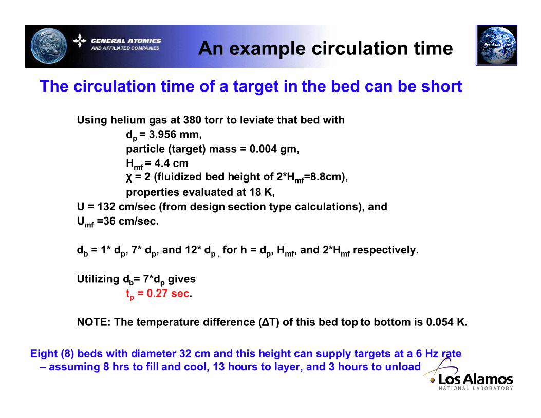
Using helium gas at 380 torr to leviate that bed withdp = 3.956 mm,particle (target) mass = 0.004 gm,Hmf = 4.4 cmχχχχ = 2 (fluidized bed height of 2*Hmf=8.8cm),properties evaluated at 18 K,
U = 132 cm/sec (from design section type calculations), andUmf =36 cm/sec.
db = 1* dp, 7* dp, and 12* dp , for h = dp, Hmf, and 2*Hmf respectively.
Utilizing db= 7*dp givestp = 0.27 sec.
NOTE: The temperature difference (∆∆∆∆T) of this bed top to bottom is 0.054 K.
An example circulation time
The circulation time of a target in the bed can be short
Eight (8) beds with diameter 32 cm and this height can supply targets at a 6 Hz rate– assuming 8 hrs to fill and cool, 13 hours to layer, and 3 hours to unload

Short circulation times mitigate effect of ∆∆∆∆T at inner ice surface
Approximate target as infinite slab with finite width
Transient thermal solutions are available for an initially uniformtemperature slab (see Figure 4-6 in Eckert and Drake)
The above conditions with slab thickness l=0.479mmproduce the following dimensionless parameters to utilize withsolution plots
x/l = 0 (ie inner surface),
HeliumCoolantTf
Adiabatic
Surface
l
k
hl= 4
ατl2 0 4= .
Wherek is DT thermal conductivity(0.30 watt/(m*K))h is the helium film heat transfer coefficient(167 watt/(m2K),αααα is DT thermal diffusivity (3.4x10⁻⁷ m2/sec),l is DT thickness,t is time (set to tp= 0.27 sec).
Solution plots yield that an initial 0.054K coolant (helium) perturbation producesonly (1-0.95)*0.054K=0.0027K temperature change at the inner ice surface in onecirculation time.
Thus, the inner ice will experience very small temperature changes.
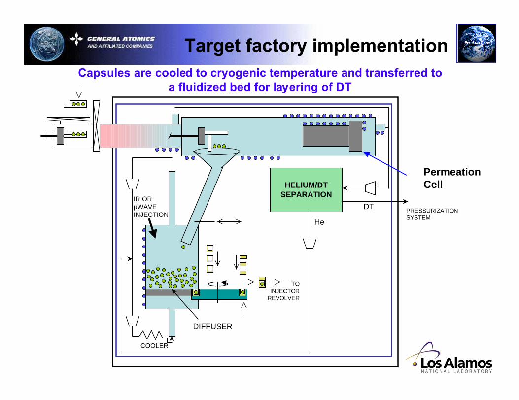
HELIUM/DTSEPARATION
DTPRESSURIZATIONSYSTEM
TOINJECTOR
REVOLVER
DIFFUSER
IR ORµWAVEINJECTION
COOLER
He
Capsules are loaded into cell and permeation filled at roomtemperature with DT
PermeationCell
Target factory implementation
Target factory implementation
HELIUM/DTSEPARATION
DTPRESSURIZATIONSYSTEM
TOINJECTOR
REVOLVER
DIFFUSER
IR ORµWAVEINJECTION
COOLER
He
Capsules are cooled to cryogenic temperature and transferred toa fluidized bed for layering of DT
PermeationCell
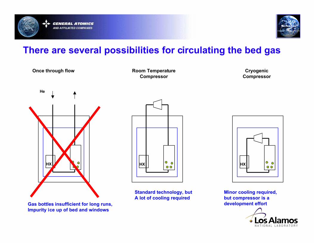
There are several possibilities for circulating the bed gas
Once through flow Room TemperatureCompressor
CryogenicCompressor
HX
He
HX HX
Gas bottles insufficient for long runs,Impurity ice up of bed and windows
Standard technology, butA lot of cooling required
Minor cooling required,but compressor is adevelopment effort
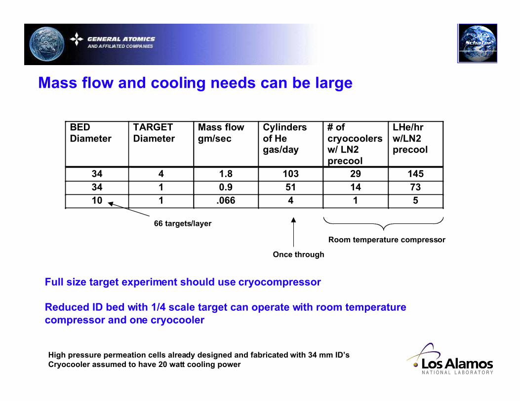
Mass flow and cooling needs can be large
High pressure permeation cells already designed and fabricated with 34 mm ID’sCryocooler assumed to have 20 watt cooling power
BEDDiameter
TARGETDiameter
Mass flowgm/sec
Cylindersof Hegas/day
# ofcryocoolersw/ LN2precool
LHe/hrw/LN2precool
34 4 1.8 103 29 14534 1 0.9 51 14 7310 1 .066 4 1 5
Room temperature compressor
Once through
Full size target experiment should use cryocompressor
Reduced ID bed with 1/4 scale target can operate with room temperaturecompressor and one cryocooler
66 targets/layer
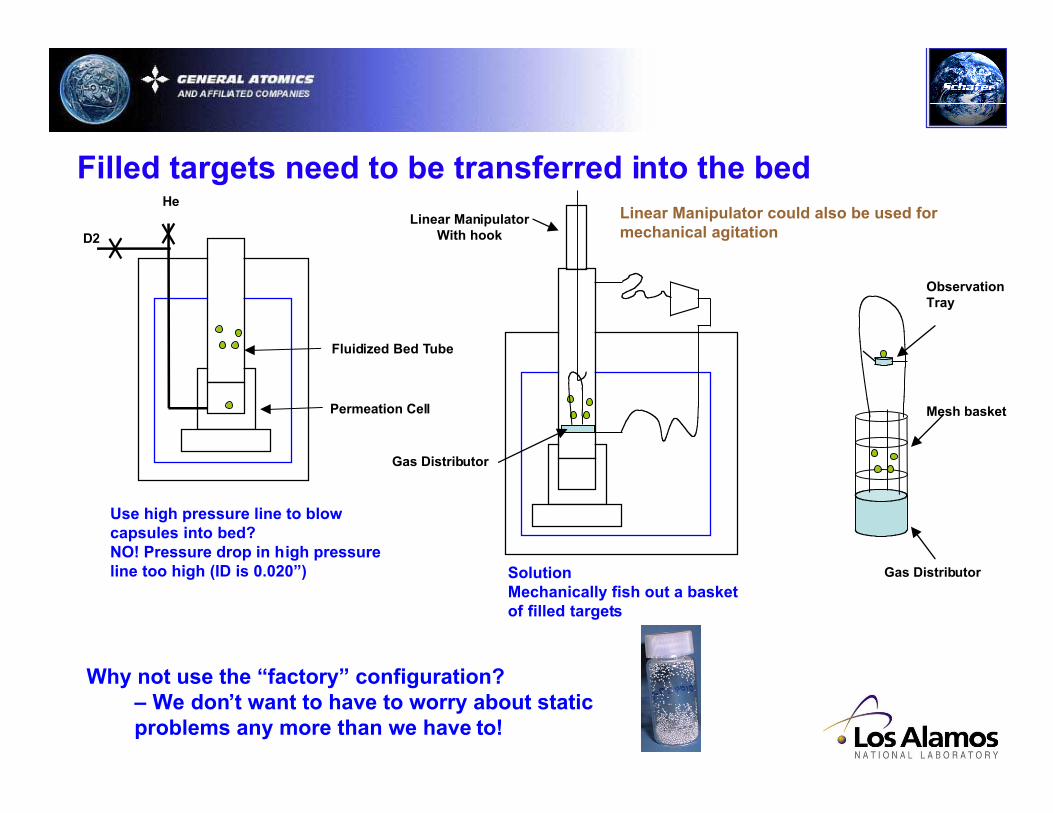
He
Use high pressure line to blowcapsules into bed?NO! Pressure drop in high pressureline too high (ID is 0.020”)
Filled targets need to be transferred into the bed
D2
Permeation Cell
Fluidized Bed Tube
Linear ManipulatorWith hook
Gas Distributor
SolutionMechanically fish out a basketof filled targets
Mesh basket
ObservationTray
Gas Distributor
Why not use the “factory” configuration?– We don’t want to have to worry about staticproblems any more than we have to!
Linear Manipulator could also be used formechanical agitation
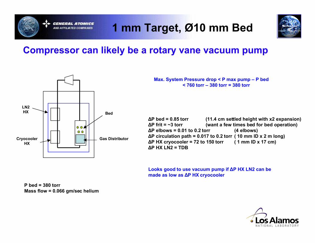
Compressor can likely be a rotary vane vacuum pump
CryocoolerHX
Max. System Pressure drop < P max pump – P bed< 760 torr – 380 torr = 380 torr
1 mm Target, Ø10 mm Bed
LN2HX Bed
Gas Distributor
∆∆∆∆P bed = 0.85 torr (11.4 cm settled height with x2 expansion)∆∆∆∆P frit = ~3 torr (want a few times bed for bed operation)∆∆∆∆P elbows = 0.01 to 0.2 torr (4 elbows)∆∆∆∆P circulation path = 0.017 to 0.2 torr ( 10 mm ID x 2 m long)∆∆∆∆P HX cryocooler = 72 to 150 torr ( 1 mm ID x 17 cm)∆∆∆∆P HX LN2 = TDB
P bed = 380 torrMass flow = 0.066 gm/sec helium
Looks good to use vacuum pump if ∆∆∆∆P HX LN2 can bemade as low as ∆∆∆∆P HX cryocooler
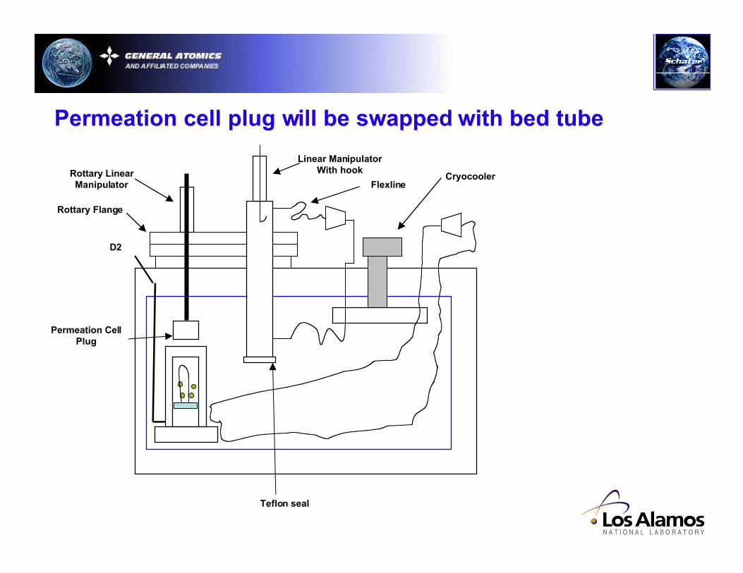
Permeation cell plug will be swapped with bed tube
Linear ManipulatorWith hookRottary Linear
Manipulator
Permeation CellPlug
D2
Rottary Flange
Flexline
Teflon seal
Cryocooler
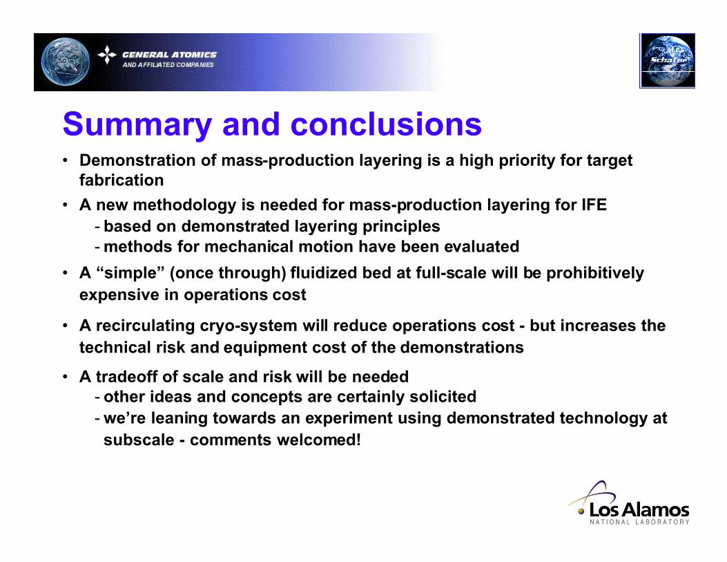
• Demonstration of mass-production layering is a high priority for targetfabrication
• A new methodology is needed for mass-production layering for IFE- based on demonstrated layering principles- methods for mechanical motion have been evaluated
• A “simple” (once through) fluidized bed at full-scale will be prohibitivelyexpensive in operations cost
• A recirculating cryo-system will reduce operations cost - but increases thetechnical risk and equipment cost of the demonstrations
• A tradeoff of scale and risk will be needed- other ideas and concepts are certainly solicited- we’re leaning towards an experiment using demonstrated technology atsubscale - comments welcomed!
Summary and conclusions