Tag-it (tm) HF-I Plus Transponder Inlays · 1-6. Tag-itHF-IPlus Transponder Inlay Rectangle –...
38
Tag-it™ HF-I Plus Transponder Inlays Reference Guide Literature Number: SCBU004B December 2005– Revised April 2010
Transcript of Tag-it (tm) HF-I Plus Transponder Inlays · 1-6. Tag-itHF-IPlus Transponder Inlay Rectangle –...

Tag-it™ HF-I Plus Transponder Inlays
Reference Guide
Literature Number: SCBU004B
December 2005–Revised April 2010

2 SCBU004B–December 2005–Revised April 2010
Copyright © 2005–2010, Texas Instruments Incorporated

Contents
Preface ....................................................................................................................................... 7
1 Introduction ........................................................................................................................ 91.1 General ..................................................................................................................... 101.2 System Description ........................................................................................................ 101.3 Product Description ....................................................................................................... 101.4 Functional Description .................................................................................................... 111.5 Memory Organization ..................................................................................................... 121.6 Command Set .............................................................................................................. 131.7 Inlay Formats and Part Numbers ........................................................................................ 13
2 Specification ..................................................................................................................... 172.1 Material Composition ...................................................................................................... 182.2 Specification Summary ................................................................................................... 192.3 Mechanical Drawings ..................................................................................................... 21
3 Shipping, Packing, and Further Handling ............................................................................. 253.1 General ..................................................................................................................... 263.2 Packing ..................................................................................................................... 263.3 Barcode Label .............................................................................................................. 273.4 Unwind From Transport Reel ............................................................................................ 273.5 Chipless Leader and Trailer .............................................................................................. 283.6 Marking of Inlays .......................................................................................................... 283.7 Static Pressure ............................................................................................................. 303.8 Tape Tension and Bending .............................................................................................. 31
4 Regulatory, Safety, and Warranty Notices ............................................................................ 334.1 Regulatory, Safety, and Warranty Notices ............................................................................. 344.2 Warranty and Liability ..................................................................................................... 344.3 Hazards From Electrostatic Discharge (ESD) ......................................................................... 344.4 Danger of Cutting Injuries ................................................................................................ 354.5 Thermal Effects ............................................................................................................ 354.6 Handling .................................................................................................................... 35
A Terms and Abbreviations ................................................................................................... 37
3SCBU004B–December 2005–Revised April 2010 Contents
Copyright © 2005–2010, Texas Instruments Incorporated

www.ti.com
List of Figures
1-1. RFID System With Reader, Antenna, and Tag-it™ HF-I Transponder............................................. 10
1-2. Schematic Structure of Tag-it HF-I Plus Transponders .............................................................. 11
1-3. Memory Organization of the Tag-it HF-I Plus Transponder.......................................................... 12
1-4. Tag-it HF-I Plus Transponder Inlay Square ............................................................................ 14
1-5. Tag-it HF-I Plus Transponder Inlay Rectangle – Large .............................................................. 14
1-6. Tag-it HF-I Plus Transponder Inlay Rectangle – Miniature .......................................................... 14
1-7. Tag-it HF-I Plus Transponder Inlay Rectangle – Medium............................................................ 15
1-8. Tag-it HF-I Plus Transponder Inlay – 24.2 mm Circular.............................................................. 15
1-9. Tag-it HF-I Plus Transponder Inlay – CD (32.5 mm Circular) ....................................................... 15
2-1. Cross-Section Area of Tag-it HF-I Plus Transponder Inlay .......................................................... 18
2-2. Dimensions of Tag-it HF-I Plus Transponder Inlay Square(RI-I11-112A).......................................... 21
2-3. Dimensions of Tag-it HF-I Plus Transponder Inlay Rectangle – Large(RI-I02-112A, RI-I02-112B) ............ 22
2-4. Dimensions of Tag-it HF-I Plus Transponder Inlay Rectangle – Miniature(RI-I03-112A) ........................ 22
2-5. Dimensions of Tag-it HF-I Plus Transponder Inlay Rectangle – Medium(RI-I15-112B) ......................... 23
2-6. Dimensions of Tag-it HF-I Plus Transponder Inlay – 24.2 mm Circular(RI-I16-112A) ........................... 23
2-7. Dimensions of Tag-it HF-I Plus Transponder Inlay – CD (32.5 mm Circular)(RI-I17-112A)..................... 24
3-1. Packing ..................................................................................................................... 26
3-2. Barcode Label.............................................................................................................. 27
3-3. Transport (Unwind) Direction ............................................................................................ 28
3-4. Leader and Trailer Configuration on the Reel ......................................................................... 28
3-5. Positioning, Function, and Indication Marks ........................................................................... 29
3-6. Marking View............................................................................................................... 29
3-7. Tape Tension and Bending .............................................................................................. 31
4 List of Figures SCBU004B–December 2005–Revised April 2010
Copyright © 2005–2010, Texas Instruments Incorporated

www.ti.com
List of Tables
1-1. Command Set for Tag-it HF-I Plus Transponder...................................................................... 13
2-1. General Specification ..................................................................................................... 19
2-2. Specification for RI-I11-112A, RI-I11-112B ............................................................................ 19
2-3. Specification for RI-I02-112A, RI-I02-112B ............................................................................ 20
2-4. Specification for RI-I03-112A ............................................................................................ 20
2-5. Specification for RI-I15-112B ............................................................................................ 20
2-6. Specification for RI-I16-112A ............................................................................................ 20
2-7. Specification for RI-I17-112A ............................................................................................ 21
3-1. Static Pressure on the Chip Area ....................................................................................... 30
3-2. Tape Tension and Bending .............................................................................................. 31
5SCBU004B–December 2005–Revised April 2010 List of Tables
Copyright © 2005–2010, Texas Instruments Incorporated

6 List of Tables SCBU004B–December 2005–Revised April 2010
Copyright © 2005–2010, Texas Instruments Incorporated
PrefaceSCBU004B–December 2005–Revised April 2010
Read This First
Edition Five – April 2010
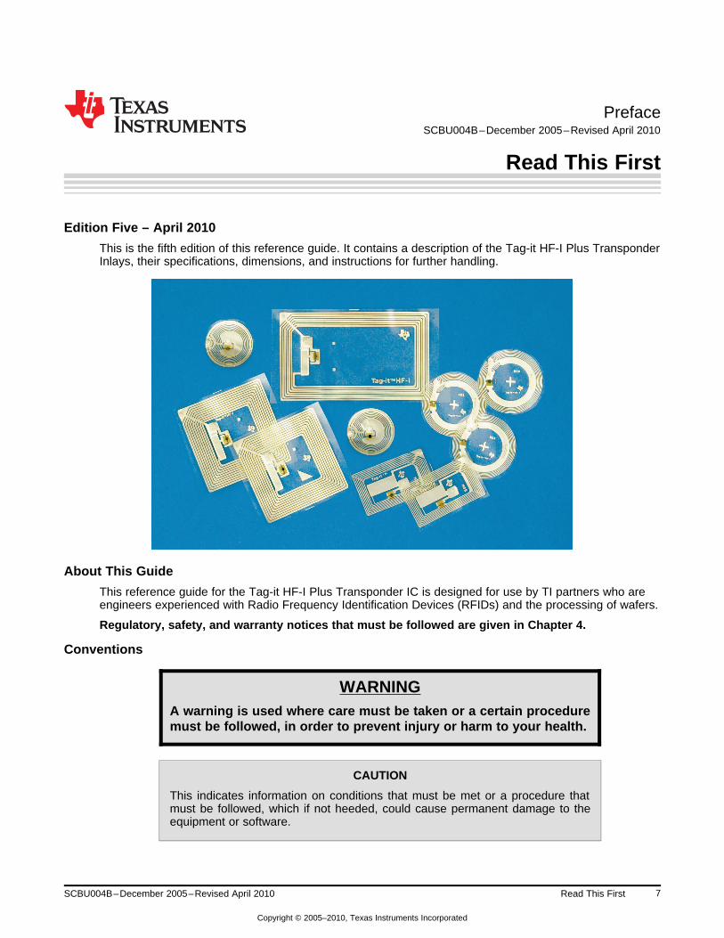
This is the fifth edition of this reference guide. It contains a description of the Tag-it HF-I Plus TransponderInlays, their specifications, dimensions, and instructions for further handling.
About This Guide
This reference guide for the Tag-it HF-I Plus Transponder IC is designed for use by TI partners who areengineers experienced with Radio Frequency Identification Devices (RFIDs) and the processing of wafers.
Regulatory, safety, and warranty notices that must be followed are given in Chapter 4.
Conventions
WARNINGA warning is used where care must be taken or a certain proceduremust be followed, in order to prevent injury or harm to your health.
CAUTION
This indicates information on conditions that must be met or a procedure thatmust be followed, which if not heeded, could cause permanent damage to theequipment or software.
7SCBU004B–December 2005–Revised April 2010 Read This First
Copyright © 2005–2010, Texas Instruments Incorporated

If You Need Assistance www.ti.com
NOTE: Indicates conditions that must be met or procedures that must be followed, to ensure properfunctioning of any equipment or software.
Information:Indicates information that makes usage of the equipment or software easier.
If You Need Assistance
For more information, please contact the sales office or distributor nearest you. This contact informationcan be found on our web site at: http://www.ti-rfid.com.
Trademarks
TIRIS, TI-RFid, and Tag-it are trademarks of Texas Instruments.
All other trademarks are the property of their respective owners.
8 Read This First SCBU004B–December 2005–Revised April 2010
Copyright © 2005–2010, Texas Instruments Incorporated
Chapter 1SCBU004B–December 2005–Revised April 2010
Introduction
This chapter introduces you to the Tag-it™ HF-I Plus Transponder Inlays.
Topic ........................................................................................................................... Page
1.1 General ............................................................................................................ 101.2 System Description ........................................................................................... 101.3 Product Description ........................................................................................... 101.4 Functional Description ....................................................................................... 111.5 Memory Organization ......................................................................................... 121.6 Command Set ................................................................................................... 131.7 Inlay Formats and Part Numbers ......................................................................... 13
9SCBU004B–December 2005–Revised April 2010 Introduction
Copyright © 2005–2010, Texas Instruments Incorporated

Reader
Tag-It HF-I Transponder
Antenna
General www.ti.com
1.1 General
The Tag-it HF-I Plus Transponder Inlay family of Texas Instruments RFID is based on the ISO/IEC 15693standard for contactless integrated circuit cards (vicinity cards) and ISO/IEC 18000-3 standard for itemmanagement. This family of various available inlay shapes form also the basis of consumable smart labelsfor use in markets requiring quick and accurate identification of items, such as:
• Express parcel delivery• Airline boarding pass and baggage handling• Electronic ticketing• Anti-counterfeit prevention• Distribution logistics and supply chain management• Building access badges• Asset tagging
The passive (no battery) transponder inlays are thin and flexible, offer a general purpose read/writecapability and are designed to be easily converted into paper or plastic labels.
The inlay is supplied on a polymer tape substrate, one web wide and delivered on reels. This allows aneasy integration into existing label manufacturing processes to produce disposable labels.
User data is written to and read from memory blocks using a non-volatile EEPROM silicon technology.Each block is separately programmable by the user and can be locked to protect data from modification.Once the data has been locked then it cannot be changed.
To give some examples, information about delivery checkpoints and timing, place of origin/destination,pallet assignments, inventory numbers and even transportation routes can be coded into the transponder.
Multiple Tag-it HF-I Plus transponder inlays, which appear in the Readers RF field, can be identified, readfrom and written to by using the Unique Identifier (UID), which is programmed and locked at the factory.
1.2 System Description
For operation, a reader with antenna is required to send a command to the transponder and to receive itsresponse (see Figure 1-1). The command of the Reader can be either in addressed or non-addressedmode. The Transponder does not transmit data until the reader sends a request (Reader talks firstprinciple).
Figure 1-1. RFID System With Reader, Antenna, and Tag-it™ HF-I Transponder
1.3 Product Description
The Tag-it HF-I Plus Transponder is compliant to the ISO/IEC 15693-2,-3 and ISO/IEC 180000-3standard. It consists of a resonance circuit assembled on a PET foil with a flip-chip mounted microchip. Analuminum antenna is used as inductor and 2 layers Aluminum on the top and bottom side of the foilfunction as capacitor. The two layers are contacted with through contacts (see figure 2). TI uses thiscapacitor to individually tune each device to a target resonance frequency. This compensates for anymaterial and process tolerances and so ensures optimal performance of every single transponder inlay.The trim target includes frequency offset to compensate detuning that will occur after further integrationinto different materials such as paper or PVC.
10 Introduction SCBU004B–December 2005–Revised April 2010
Copyright © 2005–2010, Texas Instruments Incorporated

www.ti.com Functional Description
Figure 1-2. Schematic Structure of Tag-it HF-I Plus Transponders
1.4 Functional Description
The Tag-it HF-I Plus Transponder is a low power, full duplex Transponder IC for use with passivecontactless identification transponder systems. The Transponder IC is designed to operate with a13.56-MHz carrier frequency. The ISO standard defines for some communication parameters severalmodes in order to meet different international radio regulations and different application requirements.Therefore, communication between the Reader and the Transponder (Down-Link communication) takesplace using ASK modulation index between 10% and 30% or 100% and datacoding (pulse positionmodulation) ‘1 out of 4’ or ‘1 out of 256’.
11SCBU004B–December 2005–Revised April 2010 Introduction
Copyright © 2005–2010, Texas Instruments Incorporated

Block # 1
2
3
62
63
64
1
2
DSFID
AFI
IC Version
32 bits
F U
X
User data
(2048 bits)
UID Number
(64 bits)
ApplicationConfiguration
Factory programmed
F = Factory Lock, U = User LockLock Bits
Memory Organization www.ti.com
According to ISO 15693 Up-Link communication (Transponder to Reader) can be accomplished with onesubcarrier (ASK modulation) or with two subcarrier (FSK modulation). Both modes (ASK and FSK) canoperate with either high or low data rate. The Transponder will answer in the mode it was interrogatedfrom the Reader and supports all communication parameter combinations. Up- and Down-Link areframe synchronized and CRC checksum secured. Each Tag-it HF-I Plus Transponder IC has a uniqueaddress (UID) stored in two blocks that are factory-programmed and 64 bits long (=264 differentaddresses). This can be used for addressing each transponder uniquely and individually for a one-to-oneexchange between the Reader and the Transponder. A mechanism to resolve collisions of a multiplicity oftransponders (Anticollision) is also implemented. This special feature allows multiple transponders to beread simultaneously and offers the capability to inventory in a very short time a large number oftransponders by their unique address, provided they are within the reader operating range.
Also, the Application Family Identifier (AFI) and the Data Storage Format Identifier (DSFID), which areoptional in the ISO/IEC 15693, are supported by the Tag-it HF-I Plus Transponder.
For more details about the communication between Reader and Transponder, see ISO/IEC 15693.
Besides the ISO/IEC 15693 defined functionality, the Tag-it HF-I Plus Transponder supports a range ofadditional specific functions, providing additional application flexibility for the customer:
• A second lock bit per block is designated for “Factory Lock”. That means that every block of the usermemory can be factory locked during production.
• The ISO Inventory Mode command has been defined in the standard as a stand-alone command toreceive DSFID and UID. For more system flexibility Texas Instruments’ Tag-it HF-I Plus Transponderalso allows the combination of the Inventory command with other commands (see Table 1).
• Besides the ISO/IEC 15693-3 defined commands, TI has implemented additional manufacturer specificcommands which are listed in Table 1.
1.5 Memory Organization
User data is read and stored in a 256-bit nonvolatile user memory that is organized in 64 blocks. Eachblock with 32 bit is user programmable and can be locked individually to protect data from modification.Once set, the lock bit cannot be reset. The user memory is field programmable per block. Two levels ofblock locking are supported: Individual block locking by the user (U) or individual block locking of factoryprogrammed data (F) during manufacturing. Bit 2 of the “Block Security Status” byte defined in ISO15693-3 is used to store the Factory Lock Status of the Block. Factory Block locking irreversibly protectsthe locked data from any further reprogramming. A factory-programmed block contains the IC referenceand the physical memory info (Block size and Number of Blocks) .
Figure 1-3. Memory Organization of the Tag-it HF-I Plus Transponder
12 Introduction SCBU004B–December 2005–Revised April 2010
Copyright © 2005–2010, Texas Instruments Incorporated

www.ti.com Command Set
1.6 Command Set
Table 1-1. Command Set for Tag-it HF-I Plus Transponder
REQUEST MODE (1)
REQUEST REQUEST NON-INVENTORY ADDRESSED Select AFI OPT. FLAGCODE ADDRESSED
ISO 15693 Mandatory Commands
Inventory 0x01 ü – – – ü 0
Stay Quiet 0x02 – ü – – – 0
ISO 15693 Optional Commands
Read_Single_Block 0x20 ü ü ü ü ü 0/1
Write_Single_Block 0x21 – ü ü ü – 1
Lock_Block 0x22 – ü ü ü – 1
Read_Multi_Blocks 0x23 ü ü ü ü ü 0/1
Select Tag 0x25 – ü – – – 0
Reset to Ready 0x26 – ü ü ü – 0
Write_AFI 0x27 – ü ü ü – 1
Lock_AFI 0x28 – ü ü ü – 1
Write DSFID 0x29 – ü ü ü – 1
Lock DSFID 0x2A – ü ü ü – 1
Get_System_info 0x2B ü ü ü ü ü 0
Get_M_Blk_Sec_St 0x2C ü ü ü ü ü 0
TI Custom Commands
Write_2_Blocks 0xA2 – ü ü ü – 1
Lock_2_Blocks 0xA3 – ü ü ü – 1(1) ü: Implemented
–: Not applicable0/1: Option flag needed
NOTE: The Option Flag (Bit 7) of the ISO 15693 defined Request Flags must be set to 1 for allWrite and Lock commands to respond properly.
For reliable programming, we recommend a programming time ≥10 ms before the Readersends the End Of Frame (EOF) to request the response from the Transponder.
1.7 Inlay Formats and Part Numbers
To cover the specific requirements of different applications, the Tag-it HF-I Plus Transponder Inlays areoffered in different shapes, with frequency offset options for further integration into paper or PVClamination.
13SCBU004B–December 2005–Revised April 2010 Introduction
Copyright © 2005–2010, Texas Instruments Incorporated

Inlay Formats and Part Numbers www.ti.com
Part number: RI-I11-112A (frequency offset for further integration into paper)
Part number: RI-I11-112B (frequency offset for PVC lamination)
Figure 1-4. Tag-it HF-I Plus Transponder Inlay Square
Part number: RI-I02-112A (frequency offset for further integration into paper)
Part number: RI-I02-112B (frequency offset for PVC lamination)
Figure 1-5. Tag-it HF-I Plus Transponder Inlay Rectangle – Large
Part number: RI-I03-112A (frequency offset for further integration into paper or PVC lamination)
Figure 1-6. Tag-it HF-I Plus Transponder Inlay Rectangle – Miniature
14 Introduction SCBU004B–December 2005–Revised April 2010
Copyright © 2005–2010, Texas Instruments Incorporated
www.ti.com Inlay Formats and Part Numbers
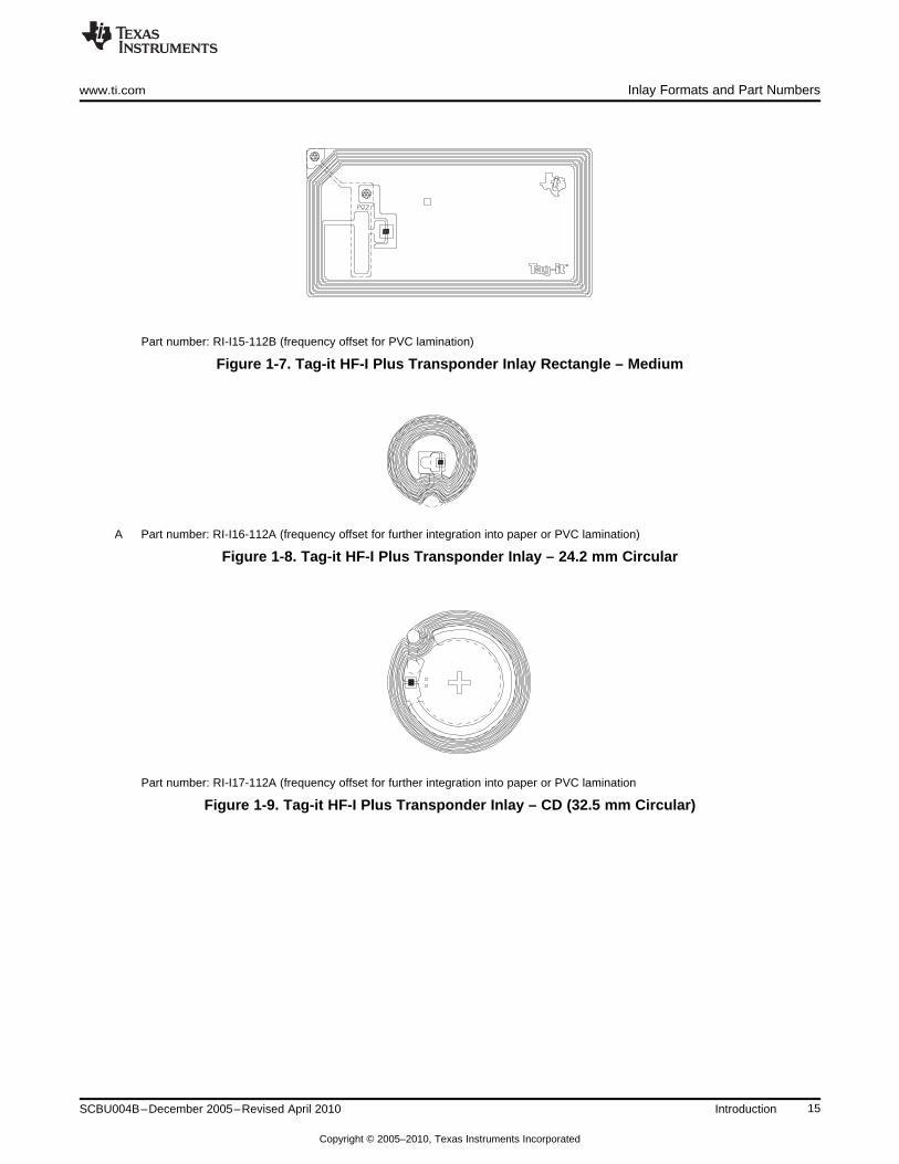
Part number: RI-I15-112B (frequency offset for PVC lamination)
Figure 1-7. Tag-it HF-I Plus Transponder Inlay Rectangle – Medium
A Part number: RI-I16-112A (frequency offset for further integration into paper or PVC lamination)
Figure 1-8. Tag-it HF-I Plus Transponder Inlay – 24.2 mm Circular
Part number: RI-I17-112A (frequency offset for further integration into paper or PVC lamination
Figure 1-9. Tag-it HF-I Plus Transponder Inlay – CD (32.5 mm Circular)
15SCBU004B–December 2005–Revised April 2010 Introduction
Copyright © 2005–2010, Texas Instruments Incorporated

16 Introduction SCBU004B–December 2005–Revised April 2010
Copyright © 2005–2010, Texas Instruments Incorporated

Chapter 2SCBU004B–December 2005–Revised April 2010
Specification
This chapter provides the electrical and mechanical specifications of the Tag-it HF-I Plus TransponderInlays.
Topic ........................................................................................................................... Page
2.1 Material Composition ......................................................................................... 182.2 Specification Summary ...................................................................................... 192.3 Mechanical Drawings ......................................................................................... 21
17SCBU004B–December 2005–Revised April 2010 Specification
Copyright © 2005–2010, Texas Instruments Incorporated

1a
1bCross-section area
2Gravure-resist ink
(Vinyl-Acryl)
3Top layer
(Aluminum)
4Glue layer
(Polyurethane)
5Basic foil
[Polyester (PET)]
6Bottom layer
(Aluminum)
Material Composition www.ti.com
2.1 Material Composition
The coil tracks, chip pads, and upper capacitor plate are etched from the top-layer aluminum. The bridgeand the bottom capacitor plate are etched from the bottom-layer aluminum.
• The surface of the foil is free of contamination by oil or grease (no fingerprints). However, there couldbe residuals of silicon-dust gravure resist on the substrate and dried residuals of PGMEA(propylene-glycol-monomethyl-ether-acetate).
• The wetability (surface energy) of the foil substrate is typically 42 mN/m.
Figure 2-1. Cross-Section Area of Tag-it HF-I Plus Transponder Inlay
18 Specification SCBU004B–December 2005–Revised April 2010
Copyright © 2005–2010, Texas Instruments Incorporated

www.ti.com Specification Summary
2.2 Specification Summary
The following table applies to all Tag-it HF-I Plus Transponder Inlay types.
Table 2-1. General Specification
Recommended operating frequency 13.56 MHz
Factory programmed read-only number 64 bits
Memory (user programmable) 2k bits organized in 64-bit × 32-bit blocks
Typical programming cycles (at 25°C) 100,000
Data retention time (at 55°C) >10 years
Simultaneous identification of tags Up to 50 tags per second (reader/antenna dependant)
Foil width 48 mm ± 0.5 mm (1.89 in ± 0.02 in)
Chip area: 0.34 mm ±0.02Thickness Antenna area (Al both sides): 0.085 mm ±0.01
Antenna area (Al one side): 0.075 mm ±0.008
Substrate: PET (Polyethylenetherephtalate)Base material Antenna: aluminum
Smallest bending radius allowed 18 mm (~0.71 in)
Tape tension (F), linear Maximum 10 N
Operating temperature –25°C to 70°C
Storage temperature (single inlay) –40°C to 85°C (warpage may occur with increasing temperature)
Storage temperature (on reel) –40°C to 40°C
Minimum 3.5 kV (Human-Body Model)ESD immunity Minimum 200 V (Machine Model)
Single-row tape wound on cardboard reel with 500-mm diameterReel outer width: approximately 60 mm (~2.36 in)Delivery Reel inner width: approximately 50 mm (~1.97 in)Hub diameter: 76.2 mm (3 in)
Typical quantity of good units per reel 5,000
NOTE: For highest possible read-out coverage, operate Readers at a modulation depth of 20% orhigher.
The following tables consist of device-specific parameters:
Table 2-2. Specification for RI-I11-112A, RI-I11-112B
PART NUMBER
RI-I11-112A RI-I11-112B
13.86 MHz ± 200 kHz (includes 14.4 MHz ± 200 kHz (includesPassive resonance frequency (at 25°C) frequency offset to compensate frequency offset to compensate
further integration into paper) PVC lamination)
Typical required activation field strength read (at 25°C) 98 dBmA/m (1) 98 dBmA/m (2)
Maximum required activation field strength read (at 25°C) 101 dBmA/m (1) 101 dBmA/m (2)
Typical required activation field strength write (at 25°C) 101 dBmA/m (1) 101 dBmA/m (2)
Antenna size 45 mm × 45 mm (~1.77 in × ~1.77 in)
Foil pitch 48 mm +0.1mm/–0.4mm (~1.89 in)(1) After integration into paper(2) After PVC lamination
19SCBU004B–December 2005–Revised April 2010 Specification
Copyright © 2005–2010, Texas Instruments Incorporated

Specification Summary www.ti.com
Table 2-3. Specification for RI-I02-112A, RI-I02-112B
PART NUMBER
RI-I02-112A RI-I02-112B
13.86 MHz ± 200 kHz (includes 14.4 MHz ± 200 kHz (includesPassive resonance frequency (at 25°C) frequency offset to compensate frequency offset to compensate
further integration into paper) PVC lamination)
Typical required activation field strength read (at 25°C) 94 dBmA/m (1) 94 dBmA/m (2)
Maximum required activation field strength read (at 25°C) 97 dBmA/m (1) 97 dBmA/m (2)
Typical required activation field strength write (at 25°C) 97 dBmA/m (1) 97 dBmA/m (2)
Antenna size 45 mm × 76 mm (~1.77 in × ~2.99 in)
Foil pitch 96 mm +0.1mm/–0.4mm (~3.78 in)(1) After integration into paper(2) After PVC lamination
Table 2-4. Specification for RI-I03-112A
PART NUMBER
RI-I03-112A
13.86 MHz ± 200 kHz (includes frequency offset to compensatePassive resonance frequency (at 25°C) further integration into paper or PVC lamination)
Typical required activation field strength read (at 25°C) 107 dBmA/m (1)
Maximum required activation field strength read (at 25°C) 109 dBmA/m (1)
Typical required activation field strength write (at 25°C) 111 dBmA/m (1)
Antenna size 22.5 mm × 38 mm (~0.89 in × ~1.5 in)
Foil pitch 48 mm +0.1 mm/–0.4 mm (~1.89 in)(1) After integration into paper or PVC lamination
Table 2-5. Specification for RI-I15-112B
PART NUMBER
RI-I15-112B
14.1 MHz ± 200 kHz (includes frequency offset to compensatePassive resonance frequency (at 25°C) PVC lamination)
Typical required activation field strength read (at 25°C) 98 dBmA/m (1)
Maximum required activation field strength read (at 25°C) 101 dBmA/m (1)
Typical required activation field strength write (at 25°C) 101 dBmA/m (1)
Antenna size 34 mm × 65 mm (~1.34 in × ~2.56 in)
Foil pitch 101.6 mm +0.1 mm/–0.4 mm (4 in)(1) After PVC lamination
Table 2-6. Specification for RI-I16-112A
PART NUMBER
RI-I16-112A
13.70 MHz ± 400 kHz (includes frequency offset to compensatePassive resonance frequency (at 25°C) further integration into paper or PVC lamination)
Typical required activation field strength read (at 25°C) 113 dBmA/m (1)
Maximum required activation field strength read (at 25°C) 116 dBmA/m (1)
Typical required activation field strength write (at 25°C) 116 dBmA/m (1)
Antenna size ø 24.2 mm +0.1 mm/–0.2 mm (~0.95 in)
Foil pitch 50.8 mm +0.1 mm/–0.3 mm (2 in)(1) After integration into paper or PVC lamination
20 Specification SCBU004B–December 2005–Revised April 2010
Copyright © 2005–2010, Texas Instruments Incorporated

www.ti.com Mechanical Drawings
Table 2-7. Specification for RI-I17-112A
PART NUMBER
RI-I17-112A
13.80 MHz ± 400 kHz (includes frequency offset to compensatePassive resonance frequency (at 25°C) further integration into paper or PVC lamination)
Typical required activation field strength read (at 25°C) 110 dBmA/m (1)
Maximum required activation field strength read (at 25°C) 113 dBmA/m (1)
Typical required activation field strength write (at 25°C) 113 dBmA/m (1)
Outer diameter: ø 32.5 mm +0.1 mm/–0.2 mm (~1.28 in)Antenna size Inner diameter: min. ø 18 mm (~0.7 in)
Foil pitch 50.8 mm +0.1 mm/–0.3 mm (2 in)(1) After integration into paper or PVC lamination
2.3 Mechanical Drawings
Figure 2-2. Dimensions of Tag-it HF-I Plus Transponder Inlay Square(RI-I11-112A)
21SCBU004B–December 2005–Revised April 2010 Specification
Copyright © 2005–2010, Texas Instruments Incorporated

Mechanical Drawings www.ti.com
Figure 2-3. Dimensions of Tag-it HF-I Plus Transponder Inlay Rectangle – Large(RI-I02-112A, RI-I02-112B)
Figure 2-4. Dimensions of Tag-it HF-I Plus Transponder Inlay Rectangle – Miniature(RI-I03-112A)
22 Specification SCBU004B–December 2005–Revised April 2010
Copyright © 2005–2010, Texas Instruments Incorporated

www.ti.com Mechanical Drawings
Figure 2-5. Dimensions of Tag-it HF-I Plus Transponder Inlay Rectangle – Medium(RI-I15-112B)
Figure 2-6. Dimensions of Tag-it HF-I Plus Transponder Inlay – 24.2 mm Circular(RI-I16-112A)
23SCBU004B–December 2005–Revised April 2010 Specification
Copyright © 2005–2010, Texas Instruments Incorporated

Mechanical Drawings www.ti.com
Figure 2-7. Dimensions of Tag-it HF-I Plus Transponder Inlay – CD (32.5 mm Circular)(RI-I17-112A)
24 Specification SCBU004B–December 2005–Revised April 2010
Copyright © 2005–2010, Texas Instruments Incorporated

Chapter 3SCBU004B–December 2005–Revised April 2010
Shipping, Packing, and Further Handling
Topic ........................................................................................................................... Page
3.1 General ............................................................................................................ 263.2 Packing ............................................................................................................ 263.3 Barcode Label ................................................................................................... 273.4 Unwind From Transport Reel .............................................................................. 273.5 Chipless Leader and Trailer ................................................................................ 283.6 Marking of Inlays ............................................................................................... 283.7 Static Pressure ................................................................................................. 303.8 Tape Tension and Bending ................................................................................. 31
25SCBU004B–December 2005–Revised April 2010 Shipping, Packing, and Further Handling
Copyright © 2005–2010, Texas Instruments Incorporated

2
4
1
4
3 1 Cardboard Reel
: 500 mm (19.7 in)
2. Cardboard Packing Box (bottom part)
3 Cardboard Packing Box (upper part)
580 mm 95 mm/ 20.8 in 3.74 in
Æ
± ´ ± ´
4. Barcode Labels (see Chapter 3.3)
General www.ti.com
3.1 General
The Tag-it HF-I Plus Transponder Inlays are delivered as single-row tape wound on cardboard reels. Eachis packed separately in a packing box.
NOTE: Delivery may contain nonfunctional inlays. These inlays are marked as described in Chapter3.5.
3.2 Packing
Figure 3-1. Packing
26 Shipping, Packing, and Further Handling SCBU004B–December 2005–Revised April 2010
Copyright © 2005–2010, Texas Instruments Incorporated

PN Part Number
QTY Quantity of functional inlays per reeltotal quantity (including nonfunctional units) may exceed this number
DC LTC Datecode; Lot Number
Malaysia
RI-I02-114A-S1
PRI-I02-114A-S1
www.ti.com Barcode Label
3.3 Barcode Label
Figure 3-2 shows the barcode label that is placed on the top side of the reel and on the front side of theupper part of its packing box.
NOTE: The following data is an example and should only be viewed as guide values. A packlist willbe enclosed with the delivery, which identifies the exact shipping details.
Figure 3-2. Barcode Label
3.4 Unwind From Transport Reel
The reel is wound up with a tension of 3 N. Each tape has a chipless leader and a trailer that isapproximately 3 m long.
NOTE: Pullstrength during unwind needs to be controlled.
27SCBU004B–December 2005–Revised April 2010 Shipping, Packing, and Further Handling
Copyright © 2005–2010, Texas Instruments Incorporated

1
2
4
3
1 Reel2 Transport (unwind)3 Chip orientation4 Antenna
1 Chipless Leader 4 First functional Transponder Inlay
2 Transponder Inlays 5 Last functional Transponder Inlay
3 Chipless Trailer (Inlay not tested) 6 Transport direction
Chipless Leader and Trailer www.ti.com
Figure 3-3. Transport (Unwind) Direction
Figure 3-3 shows the transport reel and the leader of the Tag-it HF-I Plus Transponder Inlays being pulledoff the reel.
CAUTION
A high current density of an electrostatic discharge from the foil can damagethe chip (IC). Therefore, it is recommended to use ionizer or antistatic rollers inthe manufacturing process. Any conductive parts in touch with Tag-it HF-I PlusInlays should have a high-impedance discharge to ground. We recommendapproximately 1 MΩ to avoid ESD damage.
3.5 Chipless Leader and Trailer
Figure 3-4. Leader and Trailer Configuration on the Reel
3.6 Marking of Inlays
• The foil inlay has positioning marks for optical detection by a singulating or handling tool.• Nonfunctional foil inlays are marked with a rectangular black mark near the center of the foil inlay.
28 Shipping, Packing, and Further Handling SCBU004B–December 2005–Revised April 2010
Copyright © 2005–2010, Texas Instruments Incorporated

1.8mm
1 Positioning Marks2 Indication and
Function MarksX Marking View
(see Figure 3-6)2
1Indication mark
(start section and end section)
2Function mark
(functional or nonfunctional)
Case 1:Functional Inlay (except first or last functional inlay on reel)
Case 2:Functional Inlay (first or last functional inlay on reel)
Case 3:Nonfunctional Inlay (except first or last tested inlay)
Case 4:Nonfunctional Inlay (if last inlay)
www.ti.com Marking of Inlays
Figure 3-5. Positioning, Function, and Indication Marks
Figure 3-6. Marking View
In tested area (not trailer/leader section), the following combination for indication and function marks ispossible:
29SCBU004B–December 2005–Revised April 2010 Shipping, Packing, and Further Handling
Copyright © 2005–2010, Texas Instruments Incorporated

Static Pressure www.ti.com
3.7 Static Pressure
Table 3-1. Static Pressure on the Chip Area
Static pressure on the chip area Maximum 4 N/mm2
CAUTION
Higher pressure than that specified may result in chip cracks.
30 Shipping, Packing, and Further Handling SCBU004B–December 2005–Revised April 2010
Copyright © 2005–2010, Texas Instruments Incorporated

2
3
1
1
1. Tape tension (F), linear
2 Bending Radius (chipheading away from thecenter of the radius)
3 Bending Radius (chipheading towardsthe center of the radius)
www.ti.com Tape Tension and Bending
3.8 Tape Tension and Bending
Table 3-2. Tape Tension and Bending
1 Tape tension (F), linear MAX: 10 N
Bending radius (chip heading away from the center of the radius at 7.5-N foil2 MIN: 18 mmtape tension)
Bending radius (chip heading towards the center of the radius at 7.5-N foil tape3 MIN: 18 mmtension)
NOTE: The Tag-it HF-I Plus Transponder Inlay shall not be folded. Pullstrength during unwindneeds to be controlled.
Figure 3-7. Tape Tension and Bending
31SCBU004B–December 2005–Revised April 2010 Shipping, Packing, and Further Handling
Copyright © 2005–2010, Texas Instruments Incorporated

32 Shipping, Packing, and Further Handling SCBU004B–December 2005–Revised April 2010
Copyright © 2005–2010, Texas Instruments Incorporated

Chapter 4SCBU004B–December 2005–Revised April 2010
Regulatory, Safety, and Warranty Notices
This chapter describes important safety precautions and safety regulations.
Topic ........................................................................................................................... Page
4.1 Regulatory, Safety, and Warranty Notices ............................................................ 344.2 Warranty and Liability ........................................................................................ 344.3 Hazards From Electrostatic Discharge (ESD) ........................................................ 344.4 Danger of Cutting Injuries .................................................................................. 354.5 Thermal Effects ................................................................................................. 354.6 Handling ........................................................................................................... 35
33SCBU004B–December 2005–Revised April 2010 Regulatory, Safety, and Warranty Notices
Copyright © 2005–2010, Texas Instruments Incorporated
Regulatory, Safety, and Warranty Notices www.ti.com
4.1 Regulatory, Safety, and Warranty Notices
An RFID system comprises an RF transmission device, and is therefore subject to national andinternational regulations.
A system reading from or writing to these transponders may be operated only under an experimentallicense or final approval issued by the relevant approval authority. Before any such device or system canbe marketed, an equipment authorization must be obtained form the relevant approval authority.
The Tag-it HF-I Plus Transponder Inlay has been manufactured using state-of-the-art technology and inaccordance with the recognized safety rules.
Observe precautions in operating instructions• Condition for the safe processing, handling and fault-free operation of the Tag-it HF-I Plus Transponder
Inlay is the knowledge of the basic safety regulations.• All persons who operate with the Tag-it HF-I Plus Transponder IC must observe the guidelines and
particularly the safety precautions outlined in this document.• In addition, basic rules and regulations for accident prevention applicable to the operating site must
also be considered.
4.2 Warranty and Liability
The "General Conditions of Sale and Delivery" of Texas Instruments Incorporated or a TI subsidiary apply.Warranty and liability claims for defect products, injuries to persons and property damages are void if theyare the result of one or more of the following causes:
• Improper use of the Transponders• Unauthorized assembly, operation and maintenance of the Transponders• Operation of the Transponders with defective and/or non-functioning safety and protective equipment• Failure to observe the instructions given in this document during transport, storage, assembly,
operation, maintenance and setting up of the Transponders• Unauthorized changes to the Transponders• Insufficient monitoring of the Transponders operation or environmental conditions• Repairs• Catastrophes caused by foreign bodies and natural disasters.
CAUTION
Tag-it HF-I Plus Transponder Inlays are 100% thoroughly tested. It is theresponsibility of TI´s customer to evaluate their packaging process forcompatibility with the Tag-it HF-I Plus Transponder Inlay properties and toensure through appropriate process controls that determined machine andmaterial parameter are met on an ongoing basis. TI does not accept warrantyclaims for material that has already undergone packaging or conversionprocess.
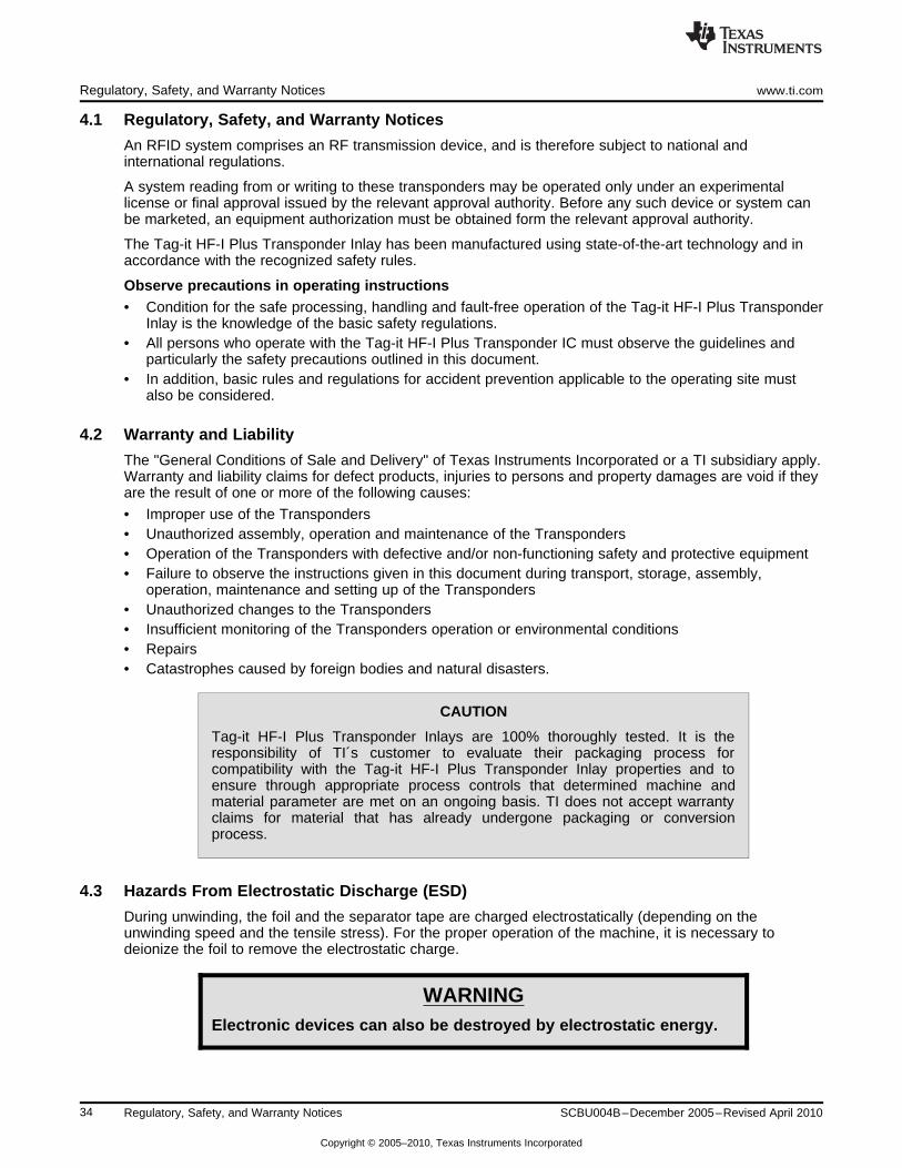
4.3 Hazards From Electrostatic Discharge (ESD)
During unwinding, the foil and the separator tape are charged electrostatically (depending on theunwinding speed and the tensile stress). For the proper operation of the machine, it is necessary todeionize the foil to remove the electrostatic charge.
WARNINGElectronic devices can also be destroyed by electrostatic energy.
34 Regulatory, Safety, and Warranty Notices SCBU004B–December 2005–Revised April 2010
Copyright © 2005–2010, Texas Instruments Incorporated

www.ti.com Danger of Cutting Injuries
4.4 Danger of Cutting Injuries
WARNINGTake care when unwinding the foil. The greater the unwindingspeed and the tensile stress, the greater the risk of receiving a cutwhen the edge of the foil is touched.
4.5 Thermal Effects
Temperatures >85°C on the foil inlay during the packaging process may result in a significant andpermanent material deformation and a possible change of color of the foil inlays, as well as a change inthe electrical characteristics.
4.6 Handling
The settings for foil unwinding and for the attendant forces must be in accordance to the information inSection 3.8.
35SCBU004B–December 2005–Revised April 2010 Regulatory, Safety, and Warranty Notices
Copyright © 2005–2010, Texas Instruments Incorporated

36 Regulatory, Safety, and Warranty Notices SCBU004B–December 2005–Revised April 2010
Copyright © 2005–2010, Texas Instruments Incorporated

Appendix ASCBU004B–December 2005–Revised April 2010
Terms and Abbreviations
A list of the abbreviations and terms used in various TI-RFid™ manuals can be found in a separatemanual:
TI-RFid™ Product Manual Terms & Abbreviations
Literature number SCBU014 (11-03-21-002)
37SCBU004B–December 2005–Revised April 2010 Terms and Abbreviations
Copyright © 2005–2010, Texas Instruments Incorporated

IMPORTANT NOTICE
Texas Instruments Incorporated and its subsidiaries (TI) reserve the right to make corrections, modifications, enhancements, improvements,and other changes to its products and services at any time and to discontinue any product or service without notice. Customers shouldobtain the latest relevant information before placing orders and should verify that such information is current and complete. All products aresold subject to TI’s terms and conditions of sale supplied at the time of order acknowledgment.
TI warrants performance of its hardware products to the specifications applicable at the time of sale in accordance with TI’s standardwarranty. Testing and other quality control techniques are used to the extent TI deems necessary to support this warranty. Except wheremandated by government requirements, testing of all parameters of each product is not necessarily performed.
TI assumes no liability for applications assistance or customer product design. Customers are responsible for their products andapplications using TI components. To minimize the risks associated with customer products and applications, customers should provideadequate design and operating safeguards.
TI does not warrant or represent that any license, either express or implied, is granted under any TI patent right, copyright, mask work right,or other TI intellectual property right relating to any combination, machine, or process in which TI products or services are used. Informationpublished by TI regarding third-party products or services does not constitute a license from TI to use such products or services or awarranty or endorsement thereof. Use of such information may require a license from a third party under the patents or other intellectualproperty of the third party, or a license from TI under the patents or other intellectual property of TI.
Reproduction of TI information in TI data books or data sheets is permissible only if reproduction is without alteration and is accompaniedby all associated warranties, conditions, limitations, and notices. Reproduction of this information with alteration is an unfair and deceptivebusiness practice. TI is not responsible or liable for such altered documentation. Information of third parties may be subject to additionalrestrictions.
Resale of TI products or services with statements different from or beyond the parameters stated by TI for that product or service voids allexpress and any implied warranties for the associated TI product or service and is an unfair and deceptive business practice. TI is notresponsible or liable for any such statements.
TI products are not authorized for use in safety-critical applications (such as life support) where a failure of the TI product would reasonablybe expected to cause severe personal injury or death, unless officers of the parties have executed an agreement specifically governingsuch use. Buyers represent that they have all necessary expertise in the safety and regulatory ramifications of their applications, andacknowledge and agree that they are solely responsible for all legal, regulatory and safety-related requirements concerning their productsand any use of TI products in such safety-critical applications, notwithstanding any applications-related information or support that may beprovided by TI. Further, Buyers must fully indemnify TI and its representatives against any damages arising out of the use of TI products insuch safety-critical applications.
TI products are neither designed nor intended for use in military/aerospace applications or environments unless the TI products arespecifically designated by TI as military-grade or "enhanced plastic." Only products designated by TI as military-grade meet militaryspecifications. Buyers acknowledge and agree that any such use of TI products which TI has not designated as military-grade is solely atthe Buyer's risk, and that they are solely responsible for compliance with all legal and regulatory requirements in connection with such use.
TI products are neither designed nor intended for use in automotive applications or environments unless the specific TI products aredesignated by TI as compliant with ISO/TS 16949 requirements. Buyers acknowledge and agree that, if they use any non-designatedproducts in automotive applications, TI will not be responsible for any failure to meet such requirements.
Following are URLs where you can obtain information on other Texas Instruments products and application solutions:
Products Applications
Amplifiers amplifier.ti.com Audio www.ti.com/audio
Data Converters dataconverter.ti.com Automotive www.ti.com/automotive
DLP® Products www.dlp.com Communications and www.ti.com/communicationsTelecom
DSP dsp.ti.com Computers and www.ti.com/computersPeripherals
Clocks and Timers www.ti.com/clocks Consumer Electronics www.ti.com/consumer-apps
Interface interface.ti.com Energy www.ti.com/energy
Logic logic.ti.com Industrial www.ti.com/industrial
Power Mgmt power.ti.com Medical www.ti.com/medical
Microcontrollers microcontroller.ti.com Security www.ti.com/security
RFID www.ti-rfid.com Space, Avionics & www.ti.com/space-avionics-defenseDefense
RF/IF and ZigBee® Solutions www.ti.com/lprf Video and Imaging www.ti.com/video
Wireless www.ti.com/wireless-apps
Mailing Address: Texas Instruments, Post Office Box 655303, Dallas, Texas 75265Copyright © 2010, Texas Instruments Incorporated