TABS Radiant Cooling Design & Control in North America · Jonathan Woolley. 436 14th St, Oakland,...
62
436 14 th St, Oakland, CA 92618 TABS Radiant Cooling Design & Control in North America: Results from Expert Interviews A Study within the “Optimizing Radiant Systems for Energy Efficiency and Comfort” Project Authors TRC Energy Services Gwelen Paliaga, PE Farhad Farahmand, PE UC Berkeley Center for the Built Environment Paul Raftery, PhD Jonathan Woolley Project Lead UC Berkeley Center for the Built Environment Prepared for California Energy Commission EPIC-14-009 CEC Manager: Jackson Thatch June 2017
Transcript of TABS Radiant Cooling Design & Control in North America · Jonathan Woolley. 436 14th St, Oakland,...

436 14th St, Oakland, CA 92618
TABS Radiant Cooling Design & Control in North America: Results from Expert Interviews A Study within the “Optimizing Radiant Systems for Energy Efficiency and Comfort” Project
Authors
TRC Energy Services Gwelen Paliaga, PE Farhad Farahmand, PE UC Berkeley Center for the Built Environment Paul Raftery, PhD Jonathan Woolley
Project Lead
UC Berkeley Center for the Built Environment
Prepared for
California Energy Commission EPIC-14-009 CEC Manager: Jackson Thatch June 2017

TABS Radiant Cooling Design & Control in North America: Results from Expert Interviews
2 | TRC Energy Services CEC EPIC 14-009
TABLE OF CONTENTS 1. INTRODUCTION AND METHODOLOGY.................................................................... 6
1.1 Interview Methodology ............................................................................................................... 6
1.2 Interview Analysis Methodology ............................................................................................... 6
1.3 Sequences of Operations Review Methodology ................................................................... 7
2. INTERVIEW RESULTS OVERVIEW .................................................................................... 8
2.1 Summary of Common Practices ............................................................................................... 8
2.2 Major Differences in Common Practices ............................................................................... 9
2.3 Opportunities to Improve on Common Practices ............................................................ 10
2.4 Summary of Unique Approaches ........................................................................................... 11
3. DETAILED INTERVIEW RESULTS .................................................................................... 12
3.1 Interviewee Background and Experience ............................................................................ 12
3.2 System Configuration ............................................................................................................... 13
3.2.1 Slab Configuration ..................................................................................................... 13
3.2.2 Supplemental Cooling ............................................................................................... 18
3.2.3 DOAS Design ............................................................................................................. 21
3.2.4 Zoning ....................................................................................................................... 23
3.3 Controls and Sequence of Operations ................................................................................ 28
3.3.1 Slab Temperature Control ......................................................................................... 28
3.3.2 Space Set Points ........................................................................................................ 33
3.3.3 Interaction with Supplemental Cooling and Mode Changeover ............................... 36
3.3.4 Condensation Control ................................................................................................ 40
3.3.5 DOAS Control ............................................................................................................. 44
3.4 Commissioning ........................................................................................................................... 46
4. DISCUSSION AND CONCLUSIONS .............................................................................. 49
4.1 System Configuration ............................................................................................................... 49
4.2 Controls and Sequence of Operations ................................................................................ 50
4.3 Commissioning ........................................................................................................................... 51
4.4 Opportunities for Improvement in Common Practice .................................................... 51
4.5 Opportunities for Further Research..................................................................................... 52
5. APPENDIX A: INTERVIEW SUMMARY TABULATION ............................................. 54

TABS Radiant Cooling Design & Control in North America: Results from Expert Interviews
3 | TRC Energy Services CEC EPIC 14-009
EXECUTIVE SUMMARY
Radiant cooling and heating has the potential for improved energy efficiency, demand response, comfort, indoor environmental quality, and architectural design. Many radiant buildings have demonstrated outstanding performance in these regards, and application of the technology in commercial buildings is expanding. However, there are no well-established best practices for design of radiant buildings and their control systems, and most professionals in the building industry are unfamiliar with radiant systems.
In this study, TRC Energy Services and the UC Berkeley Center for the Built Environment interviewed eleven prominent professionals who have substantial experience with design, construction, and operation of radiant buildings in North America, having collectively designed more than 330 radiant cooled buildings. The objective of the study was to:
♦ Document the variety of design and control approaches currently used for radiant cooled buildings,
♦ Highlight themes of common practice and variations in common practice, and
♦ Identify areas where research could be of service to practitioner needs.
We focused specifically on design and control of high thermal mass radiant systems – referred to as Thermally Activated Building Systems (TABS). A TABS system has radiant tubing embedded in a structural slab, or in a topping slab on top of a structural slab without insulation to separate the two slabs. We also include discussion of radiant systems with topping slabs separated from structural slabs by insulation – referred to as Embedded Surface Systems (ESS). Our interviews covered the following topic areas:
♦ Interviewee background
♦ System configuration
• Slab configuration
• Supplemental cooling systems
• Ventilation systems
• Zoning
♦ Controls and sequence of operation
• Slab temperature control
• Zone air temperature control
• Interaction between radiant cooling and supplemental cooling
• Condensation control
• Ventilation systems control
♦ System commissioning
The collection of interview responses revealed that there is a diverse range of approaches for design and control of TABS buildings. While there are many similar themes, interviewees also expressed unique preferences about certain aspects of design for these systems. The following characteristics were consistent among all interview responses:
♦ The upper limit of cooling capacity from radiant TABS is lower than conventional air systems. It is important to reduce building envelope and internal loads, and supplemental cooling may be required.
♦ The surface temperature for TABS changes slowly because these systems have high thermal inertia. This is both an advantage and a challenge.

TABS Radiant Cooling Design & Control in North America: Results from Expert Interviews
4 | TRC Energy Services CEC EPIC 14-009
♦ The cooling capacity from TABS is somewhat self-regulating because the rate of heat transfer to the cooled slab surface naturally and instantaneously responds to changes in the temperatures of air and other surfaces in a space.
♦ Controls are usually configured to maintain slab temperature – often measured with an embedded slab temperature sensor – by adjusting either chilled water supply temperature or flow rate.
♦ TABS buildings are usually controlled to maintain nearly constant slab temperature setpoint. The slab temperature set point is adjusted on a long time scale (seasonal or using average outdoor weather over many days), and TABS buildings are almost always operated round-the-clock without temperature setback during unoccupied periods.
On other aspects, interviewees described a variety of design strategies and had unique preferences for their typical TABS design. These topics included:
♦ Building types and space types where TABS should be applied.
♦ The choice and design of chilled water plants for buildings with radiant cooling.
♦ The design and zoning of ventilation systems.
♦ The design of supplemental cooling systems.
♦ The use of two-way valves, modulating valves, or pumps for radiant zone control.
♦ The choice of space temperature set points.
♦ The control of changeover between slab heating to slab cooling.
Most interviewees use supplemental cooling to maintain comfort where gains are higher than the radiant system capacity, or to achieve a faster response in zones that have highly variable gains such as conference rooms. Interviewees described a variety of supplemental cooling strategies, but most use the ventilation system – nearly always a Dedicated Outdoor Air System (DOAS) – as an integral part of the comfort control system. Partly for supplemental cooling, the DOAS maximum airflow rate is typically sized above code minimum ventilation requirements. Interviewees use a wide variety of zoning and control approaches for DOAS supplemental cooling.
Almost no interviewees had encountered condensation in practice. Condensation risk is always analyzed as part of design, but interviewees were split on the need for active humidity control. Some interviewees emphasized that active control of supply water temperature and/or DOAS dehumidification is critical to prevent condensation, while others emphasized that no active control is needed when a system is engineered to never reach a condensation condition during normal operation. Indoor humidity is always measured, but it is not always used for active control.
Radiant cooling operates with a relatively warm chilled water temperature (aka, high temperature cooling). A few interviewees design chillers or compressorless chilled water plants that generate water at the temperature needed for the radiant slab. However, in most cases chilled water is generated at a low temperature – to provide dehumidification, or to serve forced air cooling in portions of the building that do not include radiant – then mixed with return water to achieve the warmer temperature needed at the slab.
Interviewees explained that expert guidance from the design team is required throughout commissioning and post occupancy to ensure proper setup and operation of TABS buildings. Typically, TABS buildings require unique settings that need to be determined during occupancy under actual operating conditions; for this designers work together with buildings operators and controls contractors to fine tune operations over the first year of operation. Designers also educate building operators on how radiant systems are controlled differently than conventional air systems, and how to avoid adjustments that would reduce effectiveness or efficiency.

TABS Radiant Cooling Design & Control in North America: Results from Expert Interviews
5 | TRC Energy Services CEC EPIC 14-009
Our interviews revealed that there are many different approaches to designing and controlling TABS buildings. While each approach appears to be effective as reported by these interviewees, there is no clear industry consensus about how the alternatives compare. There are significant differences between design approaches that likely have implications for energy performance and comfort. Differences appear to be driven by project constraints, designer preference, or designer understanding of the behavior and capabilities of radiant systems. This report documents the landscape of current practice for design and control of TABS buildings in North America. The results are exhibited for public consideration and to enable the refinement and standardization of best practices.
We report all interview findings objectively based on only the interviewee responses. The goal of this report is to summarize current best practices as reported by experts. We include limited commentary from the research team only in section 4.4, Opportunities for Improvement in Common Practice, and section 4.5, Opportunities for Further Research.
Acknowledgements This work was supported by the California Energy Commission (CEC) Electric Program Investment Charge (EPIC) (EPN-14-009) "Optimizing Radiant Systems for Energy Efficiency and Comfort” and also partially by the Center for the Built Environment, University of California, Berkeley.
For more information
Gwelen Paliaga [email protected] Farhad Faramand [email protected]
For more information regarding the larger CEC EPIC Radiant Research Project:
Fred Bauman [email protected]
This study and related project work: www.cbe.berkeley.edu/research/optimizing-radiant-systems.htm

TABS Radiant Cooling Design & Control in North America: Results from Expert Interviews
6 | TRC Energy Services CEC EPIC 14-009
1. INTRODUCTION AND METHODOLOGY As part of the California Energy Commission (CEC) Electric Program Investment Charge (EPIC) project Optimizing Radiant Systems for Energy Efficiency and Comfort, and in conjunction with the Center for the Built Environment (CBE) at University of California at Berkeley, TRC Energy Services conducted research to investigate best practices for design and control of TABS radiant cooling systems for commercial buildings. This report documents the findings.
Research consisted of two parts:
1. Interviews with radiant cooling design experts 2. Review of their written sequences of operations (SOOs)
Note that all temperatures in interview summaries and SOOs are in Fahrenheit for consistency.
1.1 Interview Methodology
We conducted eleven interviews with radiant cooling experts out of twelve interview requests. To choose interviewees, we identified individuals from within our industry networks that have demonstrated substantial practical experience in design, construction, and operation of TABS radiant buildings. We asked these individuals to provide suggestions for additional interviewees. Time did not allow us to interview everyone, but we selected interviewees based on their cumulative radiant cooling design experience and in order of response to our personal inquiries.
Each interviewee had experience with many different radiant systems and a variety of design strategies. We used a structured interview method to obtain responses to the same topic areas. To reveal information about best practices, we asked interviewees to share their typical and/or preferred design approaches. In addition to documenting these preferred strategies, we also asked interviewees to comment on the motivations for each design approach, design tradeoffs, and challenges associated with implementation. Since most interviewees had experience with multiple types of radiant systems, we asked that their responses focus on design and control of TABS (rather than radiant panels or embedded surface systems), except where the recommended strategies were relevant for all radiant system types. We recorded all interviews with permission and interviewees had the choice to have their responses reported anonymously.
Each interview lasted at least one hour, and included several questions in each of the following topic areas:
♦ Interviewee design background and experience with radiant buildings
♦ System configuration
♦ Controls and sequence of operation
♦ Commissioning
1.2 Interview Analysis Methodology
Section 3 of this report documents the detailed interview responses. For each question, we provide:
♦ A narrative summary about the responses
♦ A sampling of notable quotations from specific interviewees: We cite the source of each quote unless that source wished to remain anonymous.
♦ A categorization of the range of responses and count of the number of responses in each category

TABS Radiant Cooling Design & Control in North America: Results from Expert Interviews
7 | TRC Energy Services CEC EPIC 14-009
The categorization of responses was developed after the interviews as a method to group common themes that emerged – the categories were not pre-determined multiple-choice options. The sum of responses attributed to each category does not usually add up to a total of eleven for a few reasons.
♦ Sometimes categories are not mutually exclusive, and may represent multi-part explanations. In this case, an interviewee’s responses were attributed to all appropriate categories.
♦ Many interviewees shared that their preferred approach would depend on the specific characteristics of a building. In cases where the alternative scenarios were also common, we attributed an interviewee’s responses to multiple categories. In cases where the interviewees suggested that the alternative scenarios are only used in rare or in unideal circumstances, we only counted responses regarding the common and preferred scenarios.
♦ Not all respondents answered every question directly, so the total responses to a question may be less than eleven.
All categorized interviewee responses are provided in Appendix A: Interview Summary Tabulation. The full interviewee responses match those presented in Section 3, but are provided in a format to allow the reader to follow one designer’s categorized responses to all the questions. The post-interview response categorizations were emailed to the designers for review, and many provided both confirmations and corrections to our original categorizations.
We report all interview findings objectively based on only the interviewee responses and used multiple internal reviews to remove author bias. The goal of this report is to summarize current best practices as reported by experts. We include limited commentary from the research team only in section 4.4 Opportunities for Improvement in Common Practice and section 4.5 Opportunities for Further Research.
1.3 Sequences of Operations Review Methodology
After each interview, we requested that interviewees provide example Sequences of Operations (SOOs) to cross-reference with their responses, and to provide explicit documentation of the control logic utilized. Several interviewees kindly shared SOOs for partial reproduction within this report. We provide selections from these SOOs within Section 3 to help illustrate responses to certain questions. We do not intend the excerpted SOOs to represent ideal practice, but rather illustrate one example of a specific method that appears to be a common and effective practice among many the interviewees.

TABS Radiant Cooling Design & Control in North America: Results from Expert Interviews
8 | TRC Energy Services CEC EPIC 14-009
2. INTERVIEW RESULTS OVERVIEW This section provides an overview of interview responses by identifying common practices (Section 2.1), major differences in common practice (Section 2.2), opportunities to improve common practice (Section 2.3), and a summary of unique approaches (Section 2.4). This section serves to highlight and organize results from Section 3, which documents the detailed interview responses for each interview question, including quotes and example sequences of operation.
2.1 Summary of Common Practices
Although interviewees shared a variety of alternative strategies for effective design and control of radiant systems, the compilation of responses revealed many prominent themes shared by most designers, including:
♦ Radiant system cooling capacity, thermal inertia, and zoning - Interviewees explained that because radiant systems have limited cooling capacity and high thermal inertia, it is necessary to design high performance envelopes, to reduced internal gains, and limit the variability of heat gains. At the same time, many interviewees noted that radiant cooling can remove direct solar radiation that strikes radiant surfaces much more rapidly than other types of heat gain; and for this reason, radiant floor cooling is sometimes specified in spaces with larger than normal solar gains. As explained in the next bullet, many designers prefer large radiant zones – some even aim to control the entire floor plate as a single zone. In this case, a high-performance envelope is especially important to ensure that perimeter areas do not have excessive variation in heat gain as compared to interior areas.
♦ Radiant slab temperature control - Indoor conditions in TABS buildings do not respond quickly to changes in supply water temperature or flow rate; therefore, the type of reactive control strategies traditionally used for conventional VAV systems are not useful for high mass radiant systems. Almost all interviewees shared that TABS buildings are controlled to maintain relatively constant slab temperature setpoint round-the-clock without temperature setback during unoccupied periods. Controls are configured to maintain slab temperature setpoint – measured with an embedded slab temperature sensor – by adjusting chilled water supply temperature or flow rate. The slab temperature setpoint is usually adjusted on a seasonal time scale. As heat gains and indoor comfort targets vary throughout the year, it is common for the slab temperature set point to change in response to the recent multi-day average outside air temperature. Choosing the appropriate relationship between slab temperature set point and outside air temperature typically requires tuning during the first few seasons of operation.
♦ Self-regulation of radiant surface cooling capacity - Interviewees explained that the cooling capacity of TABS systems naturally adjusts to temporal and spatial variations in heat gain. This occurs because heat transfer rate at any point on the slab surface instantaneously responds to changes in the surrounding air temperature and changes in the temperature of other surfaces in the space. Interviewees noted that this characteristic is a critical design consideration. Self-regulation is the reason that radiant systems can maintain comfort throughout large zones despite the fact that slab surface temperatures respond slowly to changes in chilled water temperature or flowrate. The temporal and spatial granularity of zone control for radiant systems is typically much coarser than for typical VAV air systems.
♦ DOAS and supplemental cooling - Most radiant system designers include supplemental cooling – sometimes in select zones and in all zones at other times. Supplemental cooling maintains comfort when gains exceed radiant system capacity, enables tighter temperature control in specific areas, and provides short term cooling capacity in spaces with highly variable gains (such as conference rooms). Designers use DOAS ubiquitously to provide fresh air ventilation in radiant buildings and often also use the DOAS to provide supplemental cooling by adjusting volume flow, supply air temperature, or both together. Most designers size DOAS 20-30% larger than minimum ventilation requirements; this is in part for supplemental cooling, but also for additional ventilation (often for LEED credits) or humidity control.

TABS Radiant Cooling Design & Control in North America: Results from Expert Interviews
9 | TRC Energy Services CEC EPIC 14-009
♦ Preventing condensation - Avoiding condensation on radiant surfaces is important, but not difficult, and can be addressed through design and appropriate set points for the floor and DOAS systems. Almost no interviewees had encountered condensation in practice. Those few that had encountered condensation problems attributed the issues to unusual situations (often during startup) or improper operation. The issues were resolved through operator training and control sequence revisions. In the collective experience of our interviewees, nobody had experienced ongoing issues with condensation.
♦ Slab Design - Most TABS designers prefer to embed radiant tubing within the structural slab. This approach is less costly than pouring a topping slab, and activates the entire thermal mass. Sometimes tubing is in a topping slab for various reasons, usually without insulation between the structural and topping slabs to maximize thermal mass.
♦ Radiant Heating- Almost all radiant cooling buildings use radiant tubing for both heating and cooling.
2.2 Major Differences in Common Practices
Among the interview responses, we also found that there are major divisions between designer preferences on some issues. For example:
♦ Appropriate space types for radiant cooling - Interviewees were divided between those that have only included radiant cooling in specific space types (lobbies, atrium, open plan spaces) and those who have had success with radiant cooling in a wide variety of space types – including private offices and high density spaces with variable gains such as classrooms and art galleries.
♦ Zone valves or pumps - Some designers prefer achieving zone control with valves, while others strongly prefer circulator pumps.
♦ Space temperature set points - Some designers recommend space air temperature set points that are similar to those used in conventional HVAC systems, while others advocate for radiant systems to operate with a wider dead band between heating and cooling.
♦ Condensation risk - Some interviewees emphasized that active control of slab supply water temperature and/or DOAS dewpoint are critical to prevent condensation, while others emphasized that they do not need active control when a system is engineered to never reach a condensation condition during normal operating conditions. Interviewees offered many examples of radiant buildings that do not have active dehumidification where space humidity or dew point sensing is only used for monitoring and alarming, not active control. Others explained that humidity sensing was critical, emphasized the importance of using good sensors with regular calibration, and often used redundant sensors for backup. Condensation control is climate dependent, which may explain some of the variation in approaches, although some of these contrasting approaches were used in the same climate.
♦ Condensation control set point - All interviewees explained that either the slab temperature set point, or the chilled water supply temperature set point is limited to avoid condensation. All interviewees measure the indoor humidity, but there are differences in how close they allow the chilled water temperature to approach the dew point. Some designers ensure that chilled water temperature stays at least 2 °F above the dew point, while others allow the chilled water temperature to drop below dew point, as long as the slab surface temperature does not.
♦ Chilled water plant size - About half of our interviewees shared that TABS buildings influence the sizing of a chilled water plant, while the other half specify a plant that is the same size as it would be for an equivalent building with conventional VAV cooling. One interviewee explained that chiller equipment could be smaller if a TABS building were controlled to store thermal energy like a flywheel, but that it is difficult to control such a system without risking discomfort occasionally, and that customer and operator expectations do not usually allow for such a control strategy.

TABS Radiant Cooling Design & Control in North America: Results from Expert Interviews
10 | TRC Energy Services CEC EPIC 14-009
♦ Slab temperature sensor location - Interviewees were divided in their preference for slab temperature sensors located at the depth of radiant tubing versus near (or at) the surface of the slab.
♦ Radiant zone control valves - Interviewees were divided in their preference for radiant floor control valve type. Most preferred 2-position on/off valves that effectively pulses water into the radiant zone with on/off control, while others prefer modulating valves that continually modulate flow.
♦ Mode changeover - Interviewees had a wide variety of approaches to control changeover between radiant slab cooling and heating modes, and emphasized the need for tuning changeover during the first year of occupancy. Interviewees were divided in the use of lockouts (e.g. time delay) between changes in mode versus slowly resetting seasonal slab temperatures. Interviewees were also divided in their concern that changes in mode can lead to energy waste when a slab changes mode too quickly, with some saying the situation should be avoided but is occasionally needed to maintain comfort.
♦ Two-pipe versus four-pipe distribution systems - Approximately half of interviewees use 2-pipe distribution for the entire building, meaning all radiant zones must be in the same mode, either heating or cooling. The other half of interviewees are evenly split between: (a) providing 4-pipe distribution to the zone level, or (b) providing 4-pipe distribution to sections of the building with 2-pipe distribution continuing to groups of zones. This later solution is a way to balance first costs with level of control – by limiting 4-pipe distribution to sections of the building that may need to be in different modes (heating or cooling) such as each floor, by orientation, or by floor and orientation. Interviewees who use 2-pipe distribution explained that with a well-designed envelope, the need for heating and cooling should change so slowly over the year and the slab setpoint will be near neutral during swing seasons.
♦ Supplemental cooling design - Interviewees had a wide variety of approaches for zoning and controlling DOAS systems to provide supplemental cooling. On one extreme the DOAS system has VAV boxes at ever zone, although most interviewees try to avoid this design because of the high initial cost. More commonly, the DOAS can vary flow or temperature at the AHU (without any zone control) to provide supplemental cooling to all zones, or the DOAS has limited zone dampers that are either pressure independent (VAV boxes) or pressure dependent (simple zone dampers). Interviewees shared a multitude of approaches and often design in response to the unique needs of each building.
2.3 Opportunities to Improve on Common Practices The interviewees discussed several common practices where the design and operation of radiant buildings could be further improved:
♦ Although the chilled water supplied to radiant systems is warmer than the chilled water for conventional VAV cooling, the chillers in many radiant buildings still generate chilled water at low temperatures. This control decision is driven by a need for low temperature chilled water used for dehumidification, or for conventional VAV systems in areas of the building where radiant cooling was not included. Interviewees recognized that this practice negates a major energy efficiency opportunity enabled by radiant cooling. Interviewee described a few buildings that supplied warmer chilled water for the radiant floor using: (a) two chilled water plants that supply different temperatures, (b) chiller in series with the lead chiller generating warmer temperature water for radiant cooling, or (c) chilled water plant supplying warmer water to the radiant system and DX used for DOAS air handlers and/or conventional VAV systems.
♦ The thermal mass and large response time for TABS can allow control sequences that strategically shift cooling plant operation to times when electricity is less expensive, or when outside temperature is better for cooling plant efficiency. However, we learned that very few TABS buildings actively employ these strategies. Many interviewees recognize this opportunity but have concerns such as; (a) limited savings because the slab temperature can only be reduced a small amount when considering the large thermal time lag of the building mass, and (b) risk of thermal discomfort. A few interviewees said that

TABS Radiant Cooling Design & Control in North America: Results from Expert Interviews
11 | TRC Energy Services CEC EPIC 14-009
weather based predictive control would be useful for radiant cooling but also noted that there are no proven algorithms that they could rely on.
♦ Although many interviewees recognized that ceiling fans could extend the comfort envelope, reduce stratification, and increase the convective cooling capacity for radiant surfaces, few had ever utilized the strategy. Some interviewees suggested that ceiling fans would be a non-starter for most commercial projects they had encountered. Others were hopeful about including the strategy in the appropriate circumstances.
♦ It is often necessary to tune radiant buildings during the first year of occupancy and to educate controls contractors and operation staff about proper system setup and management. Typically, radiant buildings require unique settings that need to be determined during occupancy and often require expert designer input to fine tune. Designers often stay engaged for the first year of occupancy even when they were not retained for ongoing commissioning services. Designers noted that these improved industry education, or development of self-tuning control sequences could help to address these challenges.
Interviewees often explained their different engineering solutions as being responsive to the varying needs of each application – including unique solutions for each building, owner, and climate. However, many interviewees seemed flexible in their approach and expressed interest in the results of this study – which we think suggests that many of the major differences listed in the previous section, Major Difference in Common Practice, are opportunities for improving common practice. Where differences in design approach exist, there may be opportunities for refinement and improvement of design solutions.
2.4 Summary of Unique Approaches
Several strategies stood apart from the others as especially unique:
♦ While many interviewees design very large zones, some prefer more granular control. At least one designer includes an automated zone control valve for every individual loop – with no more than 300 ft of tubing on each loop/zone. This designer usually used radiant in sun spaces, such as atria, and specified topping slabs insulated from structural slabs, a unique situation where radiant floor sub-zones can respond to localized solar heating.
♦ Most designers are careful to keep chilled water temperature well above the dew point. However, since the slab surface temperature is always warmer than the chilled water supply temperature, at least one designer allows supply water temperature to drop below dew point, as long as the slab temperature does not.
♦ At least one designer sizes the chilled water plant according to results from dynamic building energy simulation for the worst case 24-hour period.
♦ Active dehumidification is not always necessary. One interviewee shared that for more than twenty radiant buildings constructed in the western United States and Canada, they have never needed to include active dehumidification.
♦ Almost all designers include some sort of supplemental cooling. One interviewee often uses VAV boxes with cooling coils in the DOAS supply air stream to manage airflow and supply air temperature to individual zones.

TABS Radiant Cooling Design & Control in North America: Results from Expert Interviews
12 | TRC Energy Services CEC EPIC 14-009
3. DETAILED INTERVIEW RESULTS Section 3 documents the detailed interview responses for each question in four topic groups and several sub groups:
♦ Interviewee design background and experience with radiant buildings
♦ System configuration
• Slab configuration
• Supplemental cooling
• DOAS design
• Zoning
♦ Controls and sequence of operation
• Slab temperature control
• Space set points
• Interaction with supplemental cooling and mode changeover
• Condensation control
• DOAS control
♦ Commissioning
For each question, we provide a summary of the responses, paraphrased quotes that help to capture key ideas, sample SOOs that are illustrative of common approaches, and tables that quantify the number of responses in each category.
3.1 Interviewee Background and Experience
3.1.1.1 What was your primary role on these projects?
Most interviewees described themselves as the engineer of record or lead designer on a project, although three interviewees made the distinction that they were the principal or a consultant (Figure 1).
Figure 1.
What was your primary role on these projects? Count
Engineer of record, lead designer, or engineer 9
Overseeing principal 3
Consultant to architect 2
3.1.1.2 How many radiant cooling projects have you worked on that were TABS? Where have your radiant cooling projects been installed?
The interviewees had a wide range of experience in terms of quantity and location of TABS cooling projects (Figure 2 and Figure 3, respectively). Most had designed more than five radiant cooled buildings and collectively have designed approximately 330 radiant cooled buildings, a significant proportion of the 400 radiant cooled

TABS Radiant Cooling Design & Control in North America: Results from Expert Interviews
13 | TRC Energy Services CEC EPIC 14-009
building that have been cataloged in the CBE database1. Most had designed primarily in the United States and Canada, but several of the interviewees also designed buildings internationally. Specific locations cited include Buenos Aires, Finland, India, Kansas, Little Rock, Louisiana, Netherlands, Philadelphia, Winnipeg, and United Kingdom.
Figure 2.
How many radiant cooling projects have you worked on that were TABS? Count
1 to 5 2
6 to 10 4
11 to 20 1
More than 20 4
Figure 3.
Where have your radiant cooling projects been installed? Count
United States - west coast 1
United States - other locations 3
Canada - west coast 4
Canada - other locations 1
United States, Canada, and International 4
3.2 System Configuration
3.2.1 Slab Configuration
3.2.1.1 In what building occupancy types are TABS most appropriate?
A majority of interviewees feel that radiant can be installed for practically any occupancy type, while a few feel it is only appropriate in certain areas (Figure 4). Several of the interviewees had only applied radiant floors in large
1 The CBE radiant cooling project database was first compiled and published in 2014 with 100 buildings (citation below) and was recently updated to 400 buildings. http://bit.ly/RadiantBuildingsCBEv2 Karmann, Caroline; Schiavon, Stefano; & Bauman, Fred. (2014). Online map of buildings using radiant technologies. Proceedings of Indoor Air 2014. http://escholarship.org/uc/item/9rs8t4wb

TABS Radiant Cooling Design & Control in North America: Results from Expert Interviews
14 | TRC Energy Services CEC EPIC 14-009
open areas such as atriums, lobbies, and rooms with substantial solar gains. A few designers noted that offices pose difficulties for TABS, including acoustics, management of small individual thermal zones, and the need to accommodate flexibility for future tenant reconfiguration.
Designers who feel that radiant is appropriate for most occupancy types state that supplementary systems can be used to fine tune conditions in individual spaces or when reconfigurations occur, even when radiant floor zoning has large zones by orientation and interior/perimeter (see discussion of zoning in section 3.2.4).
♦ Peter Rumsey: “It’s always 100% of the buildings. I haven’t worked on any buildings where it’s only been in a lobby.”
♦ Peter Simmonds: “I would not use a radiant floor for an office building, but I would look at a radiant ceiling. But in a museum for example or a place with special glazing, I would look at a floor to keep a balanced surface temperature in the space.”
♦ Blair McCarry: “Radiant is most effective when you have uncontrolled solar load, and the radiant acts as a sponge for the solar loads.”
♦ Erik Olsen: “Radiant floor is more likely to be done in a one off situation where it is not the predominant system in the building. […] If it is a typical space with furniture, then our instinct is to use overhead radiant with panels or active slab.”
Figure 4.
In what building occupancy types are TABS most appropriate? Count
Radiant is appropriate for most occupancy types 7
Radiant is most appropriate in large open areas such as lobbies, atrium, museums, and airport terminals. Also areas with large solar gains. 4
Radiant is usually the predominant cooling strategy 7
Radiant is mainly only used in specific areas 3
3.2.1.2 Does your radiant design typically use tubing located in the structural slab or topping slab? Why?
The decision for the tubing to be in a structural or topping slab is not based on a strict technical constraint; interviewees explained that cost reduction is the primary motivation for using a structural slab (Figure 5). Topping slabs are also common for several reasons, including:
1. Structural engineer’s concerns about tubing within the structure 2. Potential for tubing repair without impacting structural slab 3. Allows contractor control over floor finish 4. Reduces the amount of activated mass when the topping slab is insulated from structural slab for faster
slab response time - usually to enable zoning.
Occasionally designers insulate topping slabs from structural slabs. This design path is used where floor-to-floor thermal isolation, or faster time response are desired.
♦ Peter Rumsey: “Cost is what determines whether it’s in slab or structural. Structural slab is cheaper. Insulation is sometimes put in between the slab and the structural, but I don’t normally recommend it.”
♦ Designer #1: “Topping slab, with insulation separating from structural slab. Topping gives a slightly faster response. Contractors prefer a topping slab for finish control anyway. Code sometimes requires insulation”

TABS Radiant Cooling Design & Control in North America: Results from Expert Interviews
15 | TRC Energy Services CEC EPIC 14-009
♦ Designer #2: “Topping slab allows for faster response, for a residence or school for example. [But] in a large atria the tubing can be in a structural slab, when you don't want high costs or finishing issues.”
Figure 5.
Does your radiant design typically use tubing located in the structural slab or topping slab? Why? Count
Tubing is located in the structural slab 1
Tubing is located in the topping slab 4
Either, depending on the application. 7
3.2.1.3 Do you design the active radiant surface to be the floor, ceiling, or both?
In general, interviewees seemed flexible about whether the active radiant surface should be in the floor or ceiling (Figure 6). Interviewees seemed to agree that the decision depends on application, and suggested advantages and disadvantages to each. For example, several designers noted that thermal comfort limits to prevent cold foot discomfort limit radiant floor cooling capacity. Others noted that ceilings enable a larger convective cooling rate, and that ceilings have more unobscured exposure for radiant heat transfer, particularly in areas with a lot of furniture. One interviewee was adamant that the floor should not be used for radiant cooling, but several other interviewees had almost exclusively designed radiant floor systems.
♦ Blair McCarry: “Choosing between ceiling/floor would be that a typically occupied space with furniture, then the radiant view to the floor is obstructed. We’d prefer ceiling in that case. Radiant floor is typically used in exceptional spaces where there is a lot of floor exposure, such as lobbies and atria.”
♦ John Weale: “We have done both. I prefer cooling from the floor because putting people close to mass seems to make sense. But we have been losing the argument of needing to omit carpet, so have started to move toward radiant in ceilings. This is largely for acoustical concerns associated with removing carpet.”
♦ Vladimir Mikler: “Depends on the application. In office, we tend to want to cool the ceiling. In a heating dominated climate, we will choose the floor. In cooling, we almost always design for ceiling.”
Figure 6.
Do you design the active radiant surface to be the floor, ceiling, or both? Count
Ceiling 2
Floor 2
Either, depending on the application. 6
3.2.1.4 Do you try limiting the mass of the active radiant surface, or is the mass determined by other considerations? How does the mass influence the radiant system design?
Interviewees indicated that they rarely have the ability to influence the mass of radiant systems, particularly with structural slabs (Figure 7). One interviewee expressed that where the structural engineer could be convinced to allow tubing in the structure, it was best to “take what you can get”. In applications where quicker

TABS Radiant Cooling Design & Control in North America: Results from Expert Interviews
16 | TRC Energy Services CEC EPIC 14-009
response is desired, insulated topping slabs are used to enable flexibility in the mechanical design without substantially impacting structural design.
Notably, except where quicker time response was desired, none of our interviewees discussed using mass as a design factor. Although it was acknowledged that massive systems may have very long response time, and that such response time might be used advantageously for thermal energy storage, no interviewees seemed to design the mass to achieve a desired dynamic thermal response.
♦ Peter Simmonds: “If it’s a topping slab, it generally works out to be 3-4 inch around the world. Biggest we did was 16 inch. We don’t really design around it, we don’t lead the [slab] design.”
♦ Erik Olsen: “No, I don’t try to limit mass for a quicker response time. Some see response time as a challenge, but if controlled properly it doesn't need to be a challenge. It’s just a different animal.”
Figure 7.
Do you try limiting the mass of the active radiant surface, or is the mass determined by other considerations? How does the mass influence the radiant system design?
Count
Amount of active mass is mainly determined by structural design 6
Low mass topping slabs are used where quicker thermal response is desired 3
3.2.1.5 Do your radiant designs provide both cooling and heating?
Almost always, radiant cooling systems also provide heating. Rarely, heating is provided with an alternate method (Figure 8). Designers prefer to use the same tubing infrastructure for both cooling and heating throughout the year.
♦ Tim McGinn: “Typically we’ll have a perimeter radiant panel heating system. […] In a couple of instances we use trench heaters, which are a form of convectors, but I typically use overhead radiant heating panels at the perimeter.”
♦ Erik Olsen: “If possible, but often not. In most cases it’s not the only or primary heating, because the capacity is so low, unless we could get a high performance envelope. Supplemental heating would be necessary.”
♦ Peter Simmonds: “Yes [we also use TABS for heating], depends on location. Bangkok doesn’t have a heating load, but Korea’s airport does.”
Figure 8.
Do your radiant designs provide both cooling and heating? Count
TABS radiant systems are also used for heating (if there is a need for heating). 9
Alternate method is used for heating. 2
3.2.1.6 Do you use higher chilled water temperatures than you would in typical air handling systems? What strategies do you use to generate the warmer water?

TABS Radiant Cooling Design & Control in North America: Results from Expert Interviews
17 | TRC Energy Services CEC EPIC 14-009
Without exception, radiant cooling systems operate with higher chilled water temperature (at the zone) than typical air handling systems to help reduce the likelihood for condensation and discomfort (Figure 9). However, about half of interviewees design to generate chilled water at low temperatures typical of conventional buildings (mid-40 °F), then blend with return water from radiant systems to achieve an appropriate radiant supply water temperature. The main reason for this design decision is that low temperature chilled water is also regularly utilized in DOAS equipment for dehumidification, and in air handlers and fan coils for cooling in non-radiant portions of a building.
About half of interviewees design the chilled water plant that serves the radiant system to supply higher chilled water temperature, primary with two chilled water plants (one for conventional loads and another for radiant cooling), and a few use DX cooling for conventional loads. One interviewee said that they design chillers to be in series so that the lead chiller can generate warmer temperature water for radiant cooling with better efficiency.
Several interviewees indicated that alternate plant designs could avoid the need to generate low temperature chilled water throughout the year, including use of night sky cooling, ground source or water source heat pumps, and water side economizing. While these were indicated as desirable strategies, they seem uncommon.
♦ Geoff McDonnell: “Some buildings have been whole building at 58F (high temperature) just above dew point, with large cooling coils in air systems. In other systems we blend down for radiant systems in order to allow lower chilled water for others systems, especially process loads and dehumidification. It’s becoming more common to use higher temperature chilled water, which results in a better EER at the chilled water plant.”
♦ John Weale: “In every case we can, we produce warmer chilled water at plant. Generally the savings and payback come from savings in the plant efficiency from higher chilled water temperatures. Our typical approach is to use conventional chillers with warmer set points. We are seeing a lot of air source heat pumps, we’ve also used ground source heat pumps. The Stanford project used night sky radiative cooling [instead of air cooled chillers]. The Exploratorium project used bay water for heat rejection. The David Brower center uses a cooling tower, and no chiller.”
♦ Tim McGinn: “In one case we generated chilled water only using evaporative cooling to a stratified thermal storage, and supplied slab through a mixing system. It’s becoming more common, in another system we have an air-cooled chiller that only kicks on when we can’t generate cool enough water from the evaporative cooling system.”
Figure 9.
Do you use higher chilled water temperatures than you would in typical air handling systems? What strategies do you use to generate the warmer water? Count
Conventional chiller plant 18
CHW for radiant generated at low temperature (mid 40s) then blended with return water from radiant to achieve desired supply water temperature for
radiant 8
Separate CHW plants for low temperature uses (dehumidification, fan coils) and high temperature uses (radiant) 7
CHW for radiant generated at higher temperature (50s and 60s), and alternate method used for dehumidification (including passive means, or not needed) 3
Compressorless chilled water plant 4

TABS Radiant Cooling Design & Control in North America: Results from Expert Interviews
18 | TRC Energy Services CEC EPIC 14-009
3.2.2 Supplemental Cooling
3.2.2.1 What space types need supplemental cooling to meet peak loads (in addition to the radiant slab?)
Most interviewees include supplemental cooling in spaces with highly variable heat gains, such as south facing perimeter zones or conference rooms (Figure 10). Nearly all interviewees stated that certain areas with transient high occupancy or high latent gains, such as classrooms, conferences rooms, and kitchens, are supplied with supplemental cooling to meet the rapid changes in demand or latent gains. A few interviewees explained that supplemental cooling is also needed in typical spaces (without variable or high heat gain) because of the limited capacity of TABS radiant cooling. Conversely the same number of interviewees explained that supplemental cooling should not be needed where the building envelope and internal gains are designed strategically to suit radiant cooling capacity limits. In summary, interviewees use supplemental cooling to meet peak gains that are higher than the radiant system capacity, sub-zone control to specific areas of the building, and for faster response to zones that have variable load profiles such as conference rooms. This supplemental cooling is primarily accomplished by adjusting volume flow, supply temperature, or both together (see section 3.2.2.2 for more detail)
♦ Dan Nall: “TABS do not ventilate and do not dehumidify, so you need a supplemental air system. The ventilation system also provides sensible cooling. The radiant doesn’t have a high output if there is no solar radiation. […] In almost all circumstances there is an air based supplemental cooling system.”
♦ Peter Rumsey: “Buildings with bad envelopes need supplemental cooling. In conference rooms the air provides supplemental cooling. There’s always a couple spots you need more air, but mostly the radiant can meet the load in well-designed buildings with good solar control.”
♦ Peter Simmonds: “If the air system is required to do 30% supplemental cooling, then I prefer to go to an all air system. But usually it works out that 100% of the load can be covered by the floor, and we just need ventilation air.”
Figure 10.
What space types need supplemental cooling to meet peak loads (in addition to the radiant slab?) Count
Most radiant spaces need supplemental cooling (via increased outside air or other method) 3
Some spaces need supplemental cooling due to high heat gains (e.g., conference rooms or south facing zones) 6
Usually there is no need for supplemental cooling aside from ventilation air 3
3.2.2.2 What supplemental cooling systems do you use?
Interviewees use supplemental cooling to meet peak gains that are higher than the radiant system capacity, sub-zone control to specific areas of the building, and for faster response to zones that have highly variable load profiles such as conference rooms. Supplemental cooling system design and control is a critical element of the radiant system solution and there are a wide variety of design approaches that vary based on the application and designer preferences. Interviewees described two general methods to provide this supplemental cooling:

TABS Radiant Cooling Design & Control in North America: Results from Expert Interviews
19 | TRC Energy Services CEC EPIC 14-009
1. In zones where heat gains are expected to greatly exceed TABS cooling capacity, most interviewees include fan coils, radiant ceiling panels, or VAV air supply for supplemental cooling. Spaces such as classrooms and conference rooms have large and transient heat gains that may not coincide with equal cooling needs in other parts of the building, or which may outpace the rate at which a massive radiant system can respond. Some designers shared that they exclude radiant cooling from these zones and use conventional VAV systems instead, but most projects used radiant together with supplemental cooling.
2. In zones where radiant is expected to provide most of the needed cooling capacity, interviewees provided supplemental cooling with the ventilation system, either by increasing the delivered volume flow rate, or by decreasing the supply air temperature below space temperature. A variety of specific methods were described (see Figure 11.). In some designs, both air flow and temperature are adjusted, while in other designs only one or the other is adjusted. Sometimes these air flow and temperature adjustments are made at the zone level, and other times the adjustment is made at the air handler. Some interviewees used pressure independent variable volume dampers, while others preferred pressure dependent zone dampers or simple, low-cost two position zone dampers.
Many interviewees noted that they regularly include demand controlled ventilation in radiant buildings, as it is often code required. When using the ventilation system for supplemental cooling, zoning and control sequences need to account for both supplemental cooling and demand controlled ventilation.
Two designers mentioned the use of second stage of cooling coils at VAV boxes – one designer stated that it is common while the other designer indicated it was rare.
Some designers indicated that the amount of supplemental cooling determined in the design phase could serve as guidance for whether or not radiant cooling is an appropriate cooling strategy. If the radiant system cannot remove most of the heat gains, perhaps another higher capacity system would be better suited for a particular space or building. A few designers also suggested that the need for supplemental cooling, and many of the nuances for control of massive radiant systems, could be resolved by switching from a TABS system to radiant ceiling panels.
♦ Blair McCarry: “We haven’t found that radiant can compensate fully for cooling loads, so we end up with a slightly oversized ventilation system, which provides better control and covers the loads. Typically, overhead, not displacement. Typically, the DOAS picks up about 40% of the load. We do [oversized ventilation] with return air, not 100% OSA, because we don’t want the energy penalty.”
♦ Erik Olsen: “Most commonly we have VAV boxes for every zone. This is a little expensive and complicated for offices, but for classrooms this is always the case. In private offices ventilation is controlled based on occupancy and uses a 2 position VAV box. There are also simpler zone dampers that are much less expensive than VAV boxes. In other cases, we have on/off controls that are not VAV units, another sort of damper.”
♦ Designer #1: “Louisiana project has a DOAS with a CHW coil that is dehumidifying and cooling the fresh air beyond neutral, it is providing cooling. We don’t want to reheat after dehumidification, and wanted to stay away from a desiccant.”
♦ Tim McGinn: “Our DOAS systems are designed like VAV systems, medium to low pressure distribution. Typically, just two-position boxes governed by occupancy sensors. In most cases, we’ll maintain a minimum ventilation rate of 20-25% during unoccupied hours. Then up to 100% ventilation when the space is occupied. In large conference rooms and classrooms, and other special spaces, we use the CO2 sensor to modulate up ventilation with the load, with modulating VAV boxes. The VAV boxes will have a second stage of cooling too, so that if the radiant system can’t keep up more air will be let in, but that happens very rarely.”

TABS Radiant Cooling Design & Control in North America: Results from Expert Interviews
20 | TRC Energy Services CEC EPIC 14-009
♦ Peter Simmonds: “If the air system is required to do 30% supplemental cooling, then I prefer to go to an all air system. But usually it works out that 100% of the load can be covered by the floor, and we just need ventilation air.”
♦ Geoff McDonnell: “In peak summer conditions, the overall radiant slab set point might be 65 °F with a DOAS air supply temperature of 68 °F (for interior zones) and then perimeter zones with high cooling loads get supplemental re-cool [with coils] on the DOAS air supply.”
Figure 11.
What supplemental cooling systems do you use? Count
Fan coils, especially in areas with highly variable heat gains 4
Radiant ceiling panels 3
Variable volume air handler with recirculation air 3
Adjust air handler volume, while staying above minimum ventilation rates 8
To whole building without zone dampers 2
To zone, DOAS responds to total zone demands 6
Adjust ventilation supply air temperature 8
At the air handler 7
At the zone 1
3.2.2.3 What ventilation system do you pair with radiant systems?
Nearly all interviewees typically use a DOAS to provide ventilation air, either at a neutral or below neutral temperature. The DOAS systems are most commonly variable volume, but also constant volume when appropriate. The DOAS is often used for supplemental cooling in addition to ventilation and the supplemental cooling needs often drive the DOAS system configuration. The previous section (Section 3.2.2.2) describes interviewee design approaches in detail.
Designers commonly employ demand controlled ventilation, either with occupancy sensors or CO2 sensors. In addition, interviewees explained that they often utilize natural ventilation in buildings with radiant cooling for thermal regulation where possible, in particular during shoulder seasons.
♦ Peter Simmonds: “Constant, not controlled. I try to use a constant flow and balance it. As soon as you specify a VAV system, the whole system gets value engineered to be just a VAV system.”
♦ Vladimir Mikler: “Ideally, we couple radiant with displacement ventilation. We use 100% outside air, DOAS, include heat recovery. Provide at low level and low velocity at a point that is only a few degrees cooler than desired space temperature. Where supplemental cooling is needed, we can upsize the DOAS ventilation, which operates with variable speed fan.”

TABS Radiant Cooling Design & Control in North America: Results from Expert Interviews
21 | TRC Energy Services CEC EPIC 14-009
Figure 12.
What ventilation system do you pair with radiant systems? Count
Variable volume DOAS 12
Constant volume DOAS 5
Demand controlled ventilation 4
Natural ventilation 5
3.2.3 DOAS Design
3.2.3.1 Does the DOAS ventilation supply typically include heat recovery?
Most interviewees answered that heat recovery is typically used, either from the exhaust air or through a run—around coil to reheat after dehumidification, but the strategy was not treated with as much consequence as other design elements. Inclusion of heat recovery is climate dependent.
Specific quotes:
♦ John Weale: “Almost 50/50 [between using heat recovery or not using heat recovery]. Supplemental space heating could be provided for morning warmup in mild climates. It’s not 100% OSA, so we have some recirculation. It’s tricky to do 100% recirculation during warmup because we have to shut off the bathroom exhaust.”
♦ Peter Rumsey: “We sometimes do a runaround coil, in the same AHU. Not heat recovery off of the exhaust flow in CA. Maybe in more challenging climates.”
♦ Peter Simmonds: “Depends if it’s in a heating climate. In a cooling climate, the delta T is normally too small and you get a penalty from the fan power.”
♦ Vladimir Mikler: “Yes, typically in Canada climates. This is especially worthwhile because we have much lower flows than normal air handlers.”
Figure 13.
Does the DOAS ventilation supply typically include heat recovery? Count
Usually 7
Only occasionally 2
3.2.3.2 How does the DOAS dehumidify outside air?
In most cases, interviewees use chilled water to dehumidify ventilation air at the DOAS air handler. Occasionally they report using other strategies, such as desiccant wheels or DX systems (Figure 14). Section 3.2.1.6 has additional background on designer choice of cooling source. Interviewees explained that in many cases ventilation air is cooled to a constant supply air set point that will ensure a low dew point. In some of these cases, designers supply cool ventilation air, without reheating to a neutral supply air temperature set point, to avoid the use of reheat energy.

TABS Radiant Cooling Design & Control in North America: Results from Expert Interviews
22 | TRC Energy Services CEC EPIC 14-009
A few interviewees reported confidently that they do not include mechanical dehumidification for radiant buildings in Canada or the western United States. Instead, these buildings are designed to operate with chilled water temperature that is warm enough to not result in condensation during all operating conditions. Some of these project also rely on passive cooling using operable windows.
♦ John Weale: “We might have 2 heat pumps, so one supplies CHW to the DOAS for dehumidification. A DX system is also effective for cost and energy consumption in mild climates. This is so the primary CHW plant can stay warm.”
♦ Designer #1: “The Louisiana project has a DOAS with a CHW coil that is dehumidifying and cooling the fresh air beyond neutral. It is providing cooling. We don’t want to reheat after dehumidification, and wanted to stay away from desiccant.”
♦ Vladimir Mikler: “In Canada or California we don’t bother with dehumidification at all. [When done], liquid desiccant (in one project) or just by chilled water.”
Figure 14.
How does the DOAS dehumidify outside air? Count
Dehumidification methods used
Chilled water 11
Direct expansion 2
Desiccant wheel 4
Energy recovery 1
Radiant system is designed to not require dehumidification 3
3.2.3.3 Is the DOAS sized larger than minimum ventilation requirements?
Every interviewee confirmed that DOAS equipment is typically sized larger than minimum ventilation requirements (Figure 15). One interviewee described one project that was sized only to minimum ventilation requirements, while his other projects had oversized DOASs. Usually, ventilation rates exceed ASHRAE 62.1 requirements by 20-30%. Designers often intend the added airflow capability to support supplemental cooling, and often count it toward LEED certification.
It appears that most interviewees do not consider the role of ventilation air for space cooling when outside air temperature is cooler than indoor conditions. Although airflow is often increased when supplemental cooling is needed (regardless of outside air temperature), only one interviewee briefly mentioned increasing ventilation airflow during periods when economizing would benefit cooling efficiency (but when supplemental cooling is not needed).
Specific quotes:
♦ John Weale: “Controls usually do not incorporate an economizer. OSA is controlled by DCV. Economizing is not worth the complexity. It’s 100% OSA but I wouldn’t call it economizing.”
♦ Geoff McDonnel: “Select unit to meet ASHRAE 62.2 then add 10% to provide flexibility. Then do a cooling load for the zone controls. Where cooling loads exceed slab capacity, I add airflow to account for those cooling loads during peak conditions. So the DOAS is sized for 25-30% larger than minimum.”

TABS Radiant Cooling Design & Control in North America: Results from Expert Interviews
23 | TRC Energy Services CEC EPIC 14-009
♦ Tim McGinn: “Typically don’t need to oversize, but if it’s a particularly dense room that is under DCV, we allow it to get overridden if the slab can’t keep up on temperature. We oversize the DOAS by 20-30% above ASHRAE 62.1, allows us not to have to do as much dehumidification at the plant. No recirculation, 100% OSA.”
Figure 15.
Is the DOAS sized larger than minimum ventilation requirements? Count
DOAS is sized to meet ASHRAE 62.1 or local code 2
DOAS is sized larger than minimum ventilation requirements
For LEED additional ventilation credit 6
For supplemental cooling 8
Oversized DOAS is controlled to provide economizer cooling 1
3.2.4 Zoning
3.2.4.1 Do radiant system zones have different sizing constraints than other types of systems? Are they related to manifolds, loop length, or costs of zone valves?
Many interviewees prefer TABS zones to be as large as possible - some control entire floor plates with a single control valve. In these instances, interviewees explained the importance of minimizing envelope gains. Many interviewees design a single interior zone, and two or more perimeter zones that are organized by orientation. Some designers break the floor plate into separately controlled quadrants, often matching structural grids.
On the other end of the spectrum, one interviewee controls every manifold separately, so that local areas can respond granularly as solar gains (or other heat inputs) track through different parts of a building over the course of a day. In buildings with numerous enclosed spaces such as private offices, some interviewees control 15 or more offices together (as long as they are of the same orientation). Another designer provides one control valve for each individual loop. This designer usually used radiant in sun spaces, such as atria, and specified topping slabs insulated from structural slabs – a unique situation where radiant floor sub-zones can respond to localized solar heating.
Especially for larger zones, some designers described the need for post occupancy balancing of individual loops to address comfort issues and tune to unique building thermodynamics. Some designers suggested varying the pipe spacing throughout a building in order to accommodate differences in heat gain that can be anticipated during the design phase.
Specific quotes:
♦ Blair McCarry: “You need to be aware of the heating need. Like an airport departure lounge, you have a perimeter zone, which potentially gets warmer in the winter time than the interior. In areas with higher solar loads, you may bring your pipe spacing together. In an airport, you generally zone according to the departure gates. The orientations are too long, so it may be a number of zones per orientation. You divide up something like the 30 ft structural column spacing. One zone may divide into 3 different manifolds to cut piping length.”
♦ Dan Nall: “Most of our projects use one control valve per loop, limited to 300 ft.”

TABS Radiant Cooling Design & Control in North America: Results from Expert Interviews
24 | TRC Energy Services CEC EPIC 14-009
♦ Erik Olsen: “Approach is to do very large zones. Spaces with similar orientation and programs can all be one zone. But, many clients or mechanical engineers become uncomfortable with that, so then you have smaller zones. If you had 15 offices with the same orientation, I would be comfortable for them all to be on one zone. Wouldn’t divide it more than 2.”
♦ Peter Rumsey: “Other times, I don’t do any zones, with variable temperature constant flow, to try to create an isothermal building. It depends on the size of the building – on smaller buildings one orientation would be one zone. With bigger buildings, you’re constrained by your manifolds. When manifolds are constraining, might as well give them each a control valve and make them their own zone.”
Figure 16.
Do radiant system zones have different sizing constraints than other types of systems? Are they related to manifolds, loop length, or costs of zone valves? Count
Controlled zones are as large as possible (full floor plate, several manifolds, many loops) 4
Zones are separated by orientation and/or exposure, generally with one zone per perimeter orientation (interior/exterior, multiple manifolds, several loops) 7
Zones are small (control valve for each individual manifold) 1
Zones are very small (individual loops) 1
3.2.4.2 How do you zone the radiant system in high occupancy spaces like conference rooms?
Interviewees were split on whether high occupancy spaces would have independent radiant zones. There was a consensus that high mass radiant systems usually cannot condition these spaces without supplemental cooling, even when they are independently zoned. Designers who zone high occupancy spaces independently stated that an independent radiant zone could make sense because the ventilation and supplemental cooling systems are also zoned independently. In contrast, a couple of interviewees stated that building spaces are reconfigured over time and the most flexible design has radiant everywhere, which allows for future re-configurations to provide supplemental cooling as needed.
3.2.4.3 When ventilation systems are used for supplemental cooling, how do you zone them in comparison to radiant zones?
Supplemental cooling zones usually do not align with the radiant zones. In some cases, where every loop or manifold is controlled separately, radiant zones may align with supplemental cooling zones, but more often supplemental cooling has more granular control. Some interviewees also explained that they separate air distribution zones based on ventilation requirements, and radiant cooling zones based on thermal requirements.
3.2.4.4 Do you use valves or zone circulator pumps for zone control?
It is most common to use valves for radiant zone control, though a few of our interviewees prefer to use pumps (Figure 17). Interviewees indicated that in buildings with a small number of zones that are fairly close to each other, only valves can be used, but in instances where there are many zones (or large zones) circulator pumps are used. One interviewee occasionally designs each independent radiant zone as a secondary loop with a heat exchanger and pump – this strategy is only used in buildings where radiant is in select areas of a building that are otherwise cooled with conventional VAV systems.

TABS Radiant Cooling Design & Control in North America: Results from Expert Interviews
25 | TRC Energy Services CEC EPIC 14-009
♦ Geoff McDonnell: “Modulating control valves on manifolds. I don’t like pumped zones because of risk of failure. [Two-way, two-position] modulating valve uses feedback from slab temperature sensor to make sure we are achieving slab temp set point.”
♦ Vladimir Mikler: “Prefer to divide loops into primary and secondary. Primary runs from plant to manifolds, then circulator pump for each controlled zone. Want to have a system that prevents overshooting, and keeping constant flow and modulating the supply temperature (based on return temperature, or slab temperature) provides the most reliable control of these systems.”
Figure 17.
Do you use valves or zone circulator pumps for zone control? Count
Valves are used for zone control 8
Usually valves are used, but pumps are used occasionally 1
Pumps are used for zone controls 3
Each zone is an isolated circuit with a pump and heat exchanger 1
3.2.4.5 Do your buildings allow different zones to be in heating and cooling at the same time (2-pipe systems versus 4-pipe systems)?
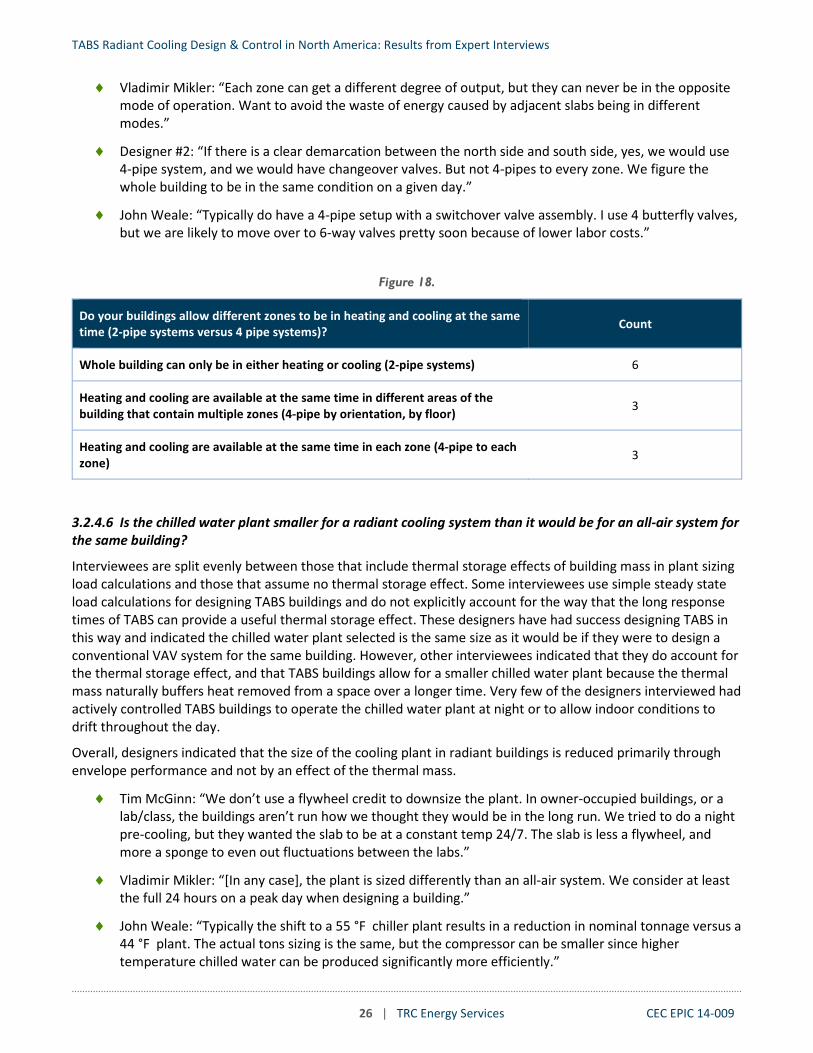
Two pipe (2-pipe) hydronic distribution consists of one supply and one return pipe that can supply one temperature water to control zones. Four pipe (4-pipe) hydronic distribution systems have two pairs of supply and return pipes that can supply different temperature water, typically hot and cold water for heating or cooling, to control zones. All zones served by a common 2-pipe distribution must be in the same mode (heating or cooling) whereas zones served by a 4-pipe distribution can be in different modes.
Approximately half of interviewees use 2-pipe distribution for the entire building, meaning all radiant zones must be in the same mode. The other half of interviewees are evenly split between: (a) providing 4-pipe distribution to the zone level, or (b) providing 4-pipe distribution to sections of the building with 2-pipe distribution continuing to groups of zones. This later solution is a way to balance first costs with level of control – by limiting 4-pipe distribution to sections of the building that may need to be in different modes (heating or cooling) such as each floor, by orientation, or by floor and orientation.
Several interviewees explained that with a well-designed envelope, the need for heating and cooling should change so slowly over the year that, during the spring or fall, no space conditioning is needed for weeks or months. A few interviewees design for natural ventilation to cover cooling requirements for many weeks of each year, during which time radiant systems are not needed.
However, several of our interviewees said that certain zones might be in heating while others are in cooling, such as core versus perimeter zones, or North-facing versus South-facing zones, requiring 4-pipe distribution to maintain comfort. A couple of interviewees noted that they only use 4-pipe to the zone in buildings with radiant ceiling panels since these systems, without high thermal inertia, might switch over from heating to cooling in the course of one day.
Section 3.3.3.3 summarizes control approaches for switching over from heating to cooling.
♦ Erik Olsen: “Usually a 2-pipe for active slabs. We have some projects with four risers, for each quadrant of the building, and each quadrant can decide whether it is in heating or in cooling. This was driven by the mechanical engineer. If you have a north side and south side that needs cooling on south and heating on north, we want to be able to provide both with radiant systems.”
TABS Radiant Cooling Design & Control in North America: Results from Expert Interviews
26 | TRC Energy Services CEC EPIC 14-009
♦ Vladimir Mikler: “Each zone can get a different degree of output, but they can never be in the opposite mode of operation. Want to avoid the waste of energy caused by adjacent slabs being in different modes.”
♦ Designer #2: “If there is a clear demarcation between the north side and south side, yes, we would use 4-pipe system, and we would have changeover valves. But not 4-pipes to every zone. We figure the whole building to be in the same condition on a given day.”
♦ John Weale: “Typically do have a 4-pipe setup with a switchover valve assembly. I use 4 butterfly valves, but we are likely to move over to 6-way valves pretty soon because of lower labor costs.”
Figure 18.
Do your buildings allow different zones to be in heating and cooling at the same time (2-pipe systems versus 4 pipe systems)? Count
Whole building can only be in either heating or cooling (2-pipe systems) 6
Heating and cooling are available at the same time in different areas of the building that contain multiple zones (4-pipe by orientation, by floor) 3
Heating and cooling are available at the same time in each zone (4-pipe to each zone) 3
3.2.4.6 Is the chilled water plant smaller for a radiant cooling system than it would be for an all-air system for the same building?
Interviewees are split evenly between those that include thermal storage effects of building mass in plant sizing load calculations and those that assume no thermal storage effect. Some interviewees use simple steady state load calculations for designing TABS buildings and do not explicitly account for the way that the long response times of TABS can provide a useful thermal storage effect. These designers have had success designing TABS in this way and indicated the chilled water plant selected is the same size as it would be if they were to design a conventional VAV system for the same building. However, other interviewees indicated that they do account for the thermal storage effect, and that TABS buildings allow for a smaller chilled water plant because the thermal mass naturally buffers heat removed from a space over a longer time. Very few of the designers interviewed had actively controlled TABS buildings to operate the chilled water plant at night or to allow indoor conditions to drift throughout the day.
Overall, designers indicated that the size of the cooling plant in radiant buildings is reduced primarily through envelope performance and not by an effect of the thermal mass.
♦ Tim McGinn: “We don’t use a flywheel credit to downsize the plant. In owner-occupied buildings, or a lab/class, the buildings aren’t run how we thought they would be in the long run. We tried to do a night pre-cooling, but they wanted the slab to be at a constant temp 24/7. The slab is less a flywheel, and more a sponge to even out fluctuations between the labs.”
♦ Vladimir Mikler: “[In any case], the plant is sized differently than an all-air system. We consider at least the full 24 hours on a peak day when designing a building.”
♦ John Weale: “Typically the shift to a 55 °F chiller plant results in a reduction in nominal tonnage versus a 44 °F plant. The actual tons sizing is the same, but the compressor can be smaller since higher temperature chilled water can be produced significantly more efficiently.”

TABS Radiant Cooling Design & Control in North America: Results from Expert Interviews
27 | TRC Energy Services CEC EPIC 14-009
Figure 19.
Is the chilled water plant smaller for a radiant cooling system than it would be for an all-air system for the same building? Count
Size is the same as a low mass building served by air system 5
Size is smaller to account for high thermal mass 5
3.2.4.7 Do you use ceiling fans with radiant? If so, how do they help?
Most of our interviewees recognized that ceiling fans may increase the cooling capacity from radiant systems, and help to achieve thermal comfort at a higher operative temperature, but very few of them commonly integrated ceiling fans in radiant buildings.
Several interviewees mentioned that most architects generally do not consider ceiling fans a viable design option, and others explained that better information is needed about the specific benefits in order to advance the design strategy. A couple of interviewees mentioned that ceiling fans would disrupt stratification from radiant floor cooling and displacement ventilation.
Those who have utilized ceiling fans said that they consider air movement as a factor that impacts thermal comfort, but that they have not specifically considered the increase in convection from radiant surfaces when designing the radiant system.
♦ John Weale: “Not an integral part. They are a safety factor. They do increase capacity of slab, and provide localized controls, which the slab cannot. We encourage clients to use them and have only gotten them in on a couple jobs.”
♦ Peter Rumsey: “I love ceiling fans, India is open to it, not so much Americas. Fans get much better heat transfer from the radiant slab, and it adds air movement.”
♦ Designer #2: “We do. Big Ass fans. For radiant ceiling, the fans help move the cold air off the floor more uniformly.”
♦ Vladimir Mikler: “So far no, mainly because of aesthetics. Often client after radiant system wants to see clean layout with no other components. Usually we want to use heavy mass radiant with displacement ventilation, [and ceiling fans] do not work well with the needs for displacement.”
Figure 20.
Do you use ceiling fans with radiant? If so, how do they help? Count
Have not included ceiling fans in any radiant project 4
Ceiling fans rarely included in some projects 5
Ceiling fans often used in projects 2

TABS Radiant Cooling Design & Control in North America: Results from Expert Interviews
28 | TRC Energy Services CEC EPIC 14-009
3.3 Controls and Sequence of Operations
3.3.1 Slab Temperature Control
3.3.1.1 How do you control radiant zones -- by varying water flow, varying water temperature, or both? If you vary flow, is it achieved by modulation (modulating valves or variable speed pump) or on/off control (cycling pumps or 2-position valves)?
Most interviewees use two position valves to regulate water flow to each zone, and some described a pulsed flow strategy for two position valves that modulates the time-averaged cooling capacity delivered to a zone. A few interviewees prefer to use modulating valves and a few prefer zone circulator pumps.
♦ John Weale: “Usually we change water flow to maintain slab temperature set points. We’ve done both modulating and 2-position [valves]. The slab temperature reacts so slowly that modulating valves effectively operate in 2-position. The primary control point is slab temp sensors, which react very slowly. […] We define a [valve] open and closed time based on demand from slab which is based on deviation from slab set point. 100% open all the time. 50% demand is open five minutes, closed five minutes. Pulse-width dependent on the slab set point.”
♦ Peter Simmonds: “I vary water flow for each zone, I have a two-way valve. Constant temperature variable flow. I never use a 2-position, always modulating, so it has good authority/control.”
♦ Designer #2: “Typically, variable flow constant temperature, and trying to get a constant delta T across the valve. We vary the flow with a circulator pump. If the zones are close, we use valves. But if there are a lot of zones, we use circulator pumps. We do have a control valve at each zone. The pump is a secondary pump. The control valve is normally modulating.”
Figure 21.
How do you control radiant zones -- by varying water flow, varying water temperature, or both? If you vary flow, is it achieved by modulation (modulating valves or variable speed pump) or on/off control (cycling pumps or 2-position valves)?
Count
Two position zone valves 6
Valve open/close position responds to set point (control sequence not described) 3
Valve open/close position is pulse-time modulated to prevent short cycling and control average capacity to maintain set point 2
Modulating zone valves 4
Pumps with 3-way control valves at the zone 3
Constant speed pump 1
Variable speed pump 1
The following example sequence of operation describes how slab temperature is controlled based on the periodic pulsing of the radiant control valve to the zone based on a proportional control loop signal.

TABS Radiant Cooling Design & Control in North America: Results from Expert Interviews
29 | TRC Energy Services CEC EPIC 14-009
The following example sequence of operation outlines control of zone circulator pumps. Note that, as opposed to the sequence above, the valve is only required to supply a specific water temperature to the zone, and there is no pulse control. Dew point control is also included in this sequence. Note the relatively high maximum space cooling set point of 77 °F , and that both the space set point and supply water set points are based linearly on outside air temperature.
Example Sequence of Operation:
Pulse Frequency Modulation for Radiant Floor Temperature Control.
For each radiant zone there shall be a slab temperature control loop which maintains the slab temperature at the zone Radiant Floor Temperature set point ± 0.5 °F (i.e., a total dead band of 1 °F). The slab temperature control loop shall control the slab temperature by periodically pulsing (opening for a set duration, and then closing) the radiant control valve, if the valve is not locked out (see previous section). The pulse duration for each zone is given in the radiant zone schedule.
The period of time between pulses (when valve is closed) shall be determined by the slab temperature control loop signal. It shall range from a maximum of 60 minutes when the loop is 5%, to a minimum of 5 minutes when the loop is 95%. If the loop is more than 95%, the valve shall be open continuously. If the loop is less than 5%, the valve shall remain closed.
Example Sequence of Operation:
Radiant Slab Manifold (Heat/Cool)
1. Radiant slab system consists of circulation pump for each manifold. A three-way temperature control valve supplies tempered water to the heating/cooling slab.
2. Provide on main chilled water and heating water return lines to each manifold open/close switchover valves, allowing either chilled water or heating water to be circulated through the manifolds and slabs.
3. Space set point shall be reset to the following adjustable schedule; 72 °F when previous 3-day’s daytime high ambient temperature is 32 °F or colder, linearly to 77 °F when previous 3-day’s daytime high ambient temperature is 68 °F or warmer. If space dew-point exceeds chilled water, reset loop temperature up by 2 °F for two hours.
4. Slab supply water temperature to be reset to 110 °F when average of the previous 3-day’s daytime high ambient temperature is 32 °F or colder, linearly to 61 °F when previous 3-day’s daytime high ambient temperature is 50 °F or warmer. Schedule shall be adjustable.
5. Heating to cooling switchover shall occur when the average of the previous 3-day’s daytime high ambient temperature rises above 50 °F and cooling to heating switchover occurs when average of the previous 3-day’s daytime high ambient temperature drops below 41 °F. Schedule shall be adjustable.
6. Monitor manifold control valve status, heating/cooling status, space set point, each space sensor temperature and supply and slab temperature. Alarm when; a) switchover occurs more than once every two days b) space temperature is maintained more than 9 °F above or below set point.
7. Cycle pump to maintain space set point in either heating or cooling mode. 8. Provide two slab temperature sensors for monitoring purposes, one in a representative heating
zone, one in a cooling zone.

TABS Radiant Cooling Design & Control in North America: Results from Expert Interviews
30 | TRC Energy Services CEC EPIC 14-009
3.3.1.2 What is the set point temperature for the water/fluid entering the slab?
Some interviewees offered rule-of-thumb for typical fluid temperature, mostly ranging from 55 to 65 °F .
One unique SOO we reviewed controlled return water temperature (to 68 °F ) as opposed to controlling supply water temperature.
♦ Geoff McDonnell: “I try to operate the radiant system at least 2 °F above [dew point]. Up here, that is about 62-63 °F , for the fluid temperature, and the slab temp would be even a bit higher.”
♦ Peter Rumsey: “Depends, but the [lower] limit is probably 56 °F . Warmest is probably 67 °F , for a project in Missouri. This temperature is reset seasonally. Some buildings may need cooling in the core in the winter. For example, in Missouri, we were supplying 70 °F water to slabs while it was snowing outside, and 67 °F in the summer.”
♦ Tim McGinn: “We don’t allow water to get below 59 °F , reset as high as 63 °F depending on the dew point feedback from a few of the sample dominant zones. Based on the dew points, on a humid day, we may reset the water temperature up a little bit.”
Figure 22.
What is the set point temperature for the water/fluid entering the slab (in cooling mode)? Count
50 – 55 °F 1
55 – 60 °F 5
60 – 65 °F 4
65 – 70 °F 1
3.3.1.3 Is the fluid temperature entering the slab controlled seasonally? How?
All interviewees controlled the slab fluid temperature – commonly the entering water temperature for cooling varies by 10-15 °F over the course of the cooling season (see 3.3.1.2). Most interviewees adjust water temperature gradually over the course of the season using a pre-determined schedule, or a function that is based on outside air temperature. (For discussion on how the supply water temperature changes from cooling to heating, see 3.3.3.3).
Some interviewees explained that for buildings with well insulated envelopes, water temperature may barely change over the course of a year.
♦ Vladimir Mikler: “If good envelope, you can set the slab temperature constant year round, or very small variation across seasons. In some projects, there is no zoning, and we operate a constant temperature building. Radiant is controlled to 4-5 degree swing between peak winter and peak summer. But there are few buildings with such excellent envelopes.”
♦ Geoff McDonnel: “I don’t generally change the water temperature more than 1-2 degrees, based on the slab temperature feedback.”
♦ Dan Nall: “The floor is off when the air system is between 40% heating and 40% cooling. When cooling load rises beyond 40%, the floor comes on with an initial temperature set point of 70 °F . As the cooling

TABS Radiant Cooling Design & Control in North America: Results from Expert Interviews
31 | TRC Energy Services CEC EPIC 14-009
load rises, the set point temperature drops from 70 °F to 68 °F . At 40% heating the floor comes on with a set point temperature of 74 °F . As heating fraction of air handler rises to 100% the floor set point rises to 80 °F . The assumption is that the building will not transition from 40% heating to 40% cooling in such a short timeframe that it will ‘thrash’ the floor.” 2
Figure 23.
Is the fluid temperature entering the slab controlled seasonally? How? Count
No 0
Yes 11
Adjusted actively on short time scale 1
Adjusted gradually throughout the year using trailing-average OAT 5
Adjusted gradually throughout the year using seasonal schedule 3
Controlled but remains nearly constant 2
3.3.1.4 Is there a slab temperature sensor? If so, where do you locate it?
All interviewees measure slab temperature. Most locate a sensor in-between the tubes, and at same level as the tubes. Three interviewees locate the sensor near the slab surface, at a depth of 1-2 inches. For large zones some interviewees averaged multiple slab temperature sensors. One interviewee had used infrared temperature sensors to measure slab surface temperature, but did not use this strategy regularly.
♦ Blair McCarry: “We have slab temp sensors, getting toward the depth of the tubing, and another about 1 inch from the surface. The one near the surface is more important.”
♦ John Weale: “5 ft from the perimeter, embedded at the level of tubing.”
♦ Peter Simmonds: “It’s pretty near to the surface, pressed in after concrete is poured. This gives it a true surface temperature. It’s a flat tablet type, 1/8 inch thick. We also use infrared surface temperatures, mounted on the wall or ceiling and looking down, within 6-feet of where all the incoming supply pipes are from the air duct because that is theoretically the coldest part of the floor. Its condensation control, and we can also see how the floor is performing.”
Figure 24.
Is there a slab temperature sensor? If so, where do you locate it? Count
In between the tubes and at the same level as the tubes 6
Near the surface of the slab 3
Infrared temperature measurement of slab surface 1
2 Dan Nall often uses ESS with topping slabs insulated from structural slabs, which have lower thermal inertia than TABS.

TABS Radiant Cooling Design & Control in North America: Results from Expert Interviews
32 | TRC Energy Services CEC EPIC 14-009
3.3.1.5 Is the slab temperature measured and controlled?
Nearly all interviewees measure and control the slab temperature. However, many indicated that the slab temperature setpoint is held nearly constant without active control loops that change the slab temperature setpoint. These cases include buildings with low variability in heat gain that are intended to operate isothermally and buildings where DOAS supplemental cooling is used for comfort control. When supplemental cooling is used for comfort control, zone air temperature sensors (thermostats) are used for supplemental cooling control, usually completely independent from slab temperature control. A couple designers reset slab temperature cooler if zone air temperature rises above set point, indicating a shortage of cooling capacity.
Other interviewees vary slab temperature based on a seasonal schedule or a formula that uses an OAT trailing average. Some interviewees mentioned interest in using predictive weather to set the slab temperature, but have not yet put the method to practice because they are not aware of any simple and proven approach.
Many interviewees said that TABS radiant requires tuning of slab temperature set points during the first year of operation to maintain comfort (see section 3.4). Upon reviewing SOOs, some designers include provisions to allow operators to adjust the slab temperature set point up or down by 2 °F from the predetermined seasonally varying values.
♦ Geoff McDonnell: “Based on average outdoor air. For example, in December or January you have a [slab] set point, then drop it to 78 °F in February, March to 75 °F, by April to 73 °F, June you’re approaching 70 °F, July you’re at 68 °F, and in September it’s 64 °F.”
♦ John Weale: “Our general approach is a constant slab temperature reset on a narrow band (+/- 2F˚) based on the dry bulb temperature measurement in the space. The chilled water temperature is linearly based on outside air. Every slab zone has a slab sensor, and an air temperature sensor. We let control contractor to choose whether it is PID, trim and respond, or just proportional – they all work.”
♦ Designer #2: “Set point is pretty much a steady state, trying to keep things simplified. The ventilation air is what tweaks the space temperature. The [temperature] you want to control is the space sensor. The slab sensor is more to prevent thermal shock and provide trending.”
♦ Peter Rumsey: “Typically the slab temperature is not controlled. We control the supply water temperature and the zone temperature sensor, or the return water temperature as a proxy for the slab temperature sensor. My preference is based only on the supply temperature, and fine tuning with the ventilation air.”
♦ Vladimir Mikler: “We have an outdoor reset based on a long term average outdoor temp. In the past, we extrapolate based on the 3-day trailing average outdoor air temperatures. For each zone, there is a corresponding (a linear regression curve) between the peak cooling output and the zero output when cooling season starts. This is only a few degrees of difference at most.”

TABS Radiant Cooling Design & Control in North America: Results from Expert Interviews
33 | TRC Energy Services CEC EPIC 14-009
Figure 25.
Is the slab temperature measured and controlled? Count
Slab temperature is measured but not controlled 1
Slab temperature is measured and controlled 12
Slab temperature set point is reset (OA reset, thermostat deviation from set point) 5
Slab temperature set point remains nearly constant 6
The following example sequence of operation outlines one method for how to calculate the radiant slab set point according to a trailing average of outdoor air temperature, and a linear function based on peak heating and cooling scenarios. This sequence records temperatures hourly, while another SOO recorded temperatures every 15 minutes.
3.3.2 Space Set Points
3.3.2.1 What are the typical space temperature set points in heating? In cooling?
Interviewees were split on use of conventional space temperature cooling set points (~75 °F ) or use of higher cooling set points (~77-78 °F ), with slightly more using higher set points than conventional. Designers that use conventional set points cite owner preferences and their experience in the field. Designers using higher set points indicated that radiant cooling enables comfort at a higher air temperature, or a desire to maintain a wide dead band between cooling and heating because indoor temperatures tend to vary more in radiant buildings, making narrow deadbands impractical.
Heating set point remains the same as in conventional buildings (68-70 °F ). Most interviewees noted that they use dry bulb temperature measurements and not operative temperature sensors because operative sensors are not typically available.
♦ Peter Rumsey: “Similar to what we need normally. The biggest barrier is cultural. In India, 76/77 is OK, but in USA we need to keep in the low 70s.”
Sequence of Operation:
Radiant slab temperature set point (as monitored and indicated from the immersion slab temperature sensors) for each zone is calculated as follows:
1. DDC keeps track of the long-term “trailing average daily outdoor air (dry-bulb) temperature (OAT)”. Outdoor air temperature readings are recorded hourly. Number of days determining the averaging time period is set through DDC. The default period shall be set to two days.
2. Zone slab temperature set point (RST) is calculated daily from the linear function derived from the set points defined for peak heating and cooling conditions and the current “trailing average daily outdoor dry bulb temperature (OATadb)”. Default settings for each radiant zone (adjustable through DDC) are as follows:
a. Heating Peak: 79 °F at 49 °F (OATadb). b. Cooling Peak: 64 °F RST at 90 °F (OATadb). c. Corresponding Linear Function: RST = -02.x (OATadb) + 82 °F.
3. Also provide manual set point override for each zone RST.

TABS Radiant Cooling Design & Control in North America: Results from Expert Interviews
34 | TRC Energy Services CEC EPIC 14-009
♦ Peter Simmonds: “The actual set point is comfort set points, PMV +/- 0.5, dynamic comfort control based on ASHRAE 55.”
Figure 26.
What are the typical space temperature set points in heating? In cooling? Count
Set points are similar to conventional all air buildings 3
Set points have a wider dead band than conventional buildings 5
3.3.2.2 Does the radiant system operate outside of occupied hours? If so, how?
In nearly every case discussed, high mass radiant cooling systems are enabled 24/7. In a few scenarios the zone temperature set points are maintained at all times, but more often the space and slab temperature set points are set back during non-occupied periods. A few interviewees only allow free cooling with water side economizer (chillers disabled) during unoccupied periods (see example SOO in section 3.3.2.3). However, interviewees explained that the setback achieved by a radiant system is small, and that the long response time for TABS requires earlier start up times and presents morning discomfort risks.
♦ John Weale: “We have the capability for setback at night, and we give it about half the setback as in an air-cooled building, and twice the warmup time. We leave it in the hands of the building operator. It could be worth it if they’re setback from 7pm-5am.”
♦ Vladimir Mikler: “Sometimes, we may have a 1 °F setback overnight, but we need to start the system a few hours before the space is occupied.”
♦ Peter Simmonds: “The typical setback for a VAV system is 65 °F . The difference between 65 °F and 68 °F (the heating set point for radiant heating) is small, so may as well keep it simple and not have the set back. It’s only the pump running through [during setback mode], I don’t start the chiller up.”
Figure 27.
Does the radiant system operate outside of occupied hours? If so, how? Count
Radiant enabled at all times with constant space temperature set points during both occupied and unoccupied periods 4
Radiant enabled at all times and space cooling temperature set point is increased during unoccupied periods 4
Radiant disabled at night except to maintain set back temperature 2
3.3.2.3 Do you often use the radiant slab for building pre-cooling? Are there issues or limitations? How do you limit overcooling?
Every interviewee was familiar with how pre-cooling with massive radiant systems might reduce peak electrical demand and enable plant operation during more efficient periods. However, only a few had incorporated such a strategy into a building they had designed - citing motivation to improve plant efficiency, reduce peak demand, or to reduce peak plant load. One interviewee indicated that precooling may be used in advance of occasional very high heat gain situations (such as a gallery opening at an art museum), but no one indicated that pre-cooling is an integral aspect of the TABS buildings they have designed. Some interviewees expressed that pre-

TABS Radiant Cooling Design & Control in North America: Results from Expert Interviews
35 | TRC Energy Services CEC EPIC 14-009
cooling the radiant slab has minimal energy savings potential with TABS. Many interviewees said that pre-cooling is risky and hard to control correctly to prevent cold discomfort in the morning, given the high thermal mass and long response time of TABS.
♦ Geoff McDonnell: “The slab stays working 24-7. Night setback on a slab or topping system is ridiculous. It uses more energy in recovery and causes discomfort. I don’t really do precooling, I only use the air-side surface for the quick reaction if needed.”
♦ Blair McCarry: “If the east zone is going to get solar loads in the morning, there will be scheduled pre-cooling so that it is ready to be more of a heat sink.”
♦ Designer #1: “We do this with the air side, but not with the slab. We do have a morning warm-up for the radiant system, but not a morning cool-down.”
Figure 28.
Do you often use the radiant slab for building pre-cooling? Are there issues or limitations? How do you limit overcooling? Count
Pre-cooling is not being used 6
Have occasionally used pre-cooling 7
To operate plant in a more efficient way 3
To reduce peak electrical demand 1
To reduce size of chiller 2
The following example sequence of operation outlines a compressorless night-time pre-cooling strategy based on OAT trailing average data. Note that macro-zones are groups of many zones based on orientation and/or space function.
Example Sequence of Operation:
Thermally Active Building System (TABS) Slab Control
1. Generally, during cooling season, when previous 3-day’s daytime high ambient temperature is 61°F or warmer, all areas served with a radiant cooling slab will be flushed with cool water during unoccupied hours until slab temperatures in each “macro zones” are reached. During night cycle, the slab is flushed with cooling water generated only by the closed loop cooling tower system to depress “macro zones” average building slab temperature.
2. The slab temperature sensors indicated on the drawings and the manifold control valves shall be used to allow slab flow in “macro zones” to be controlled individually. Slab temperature sensors shall be used to monitor night slab temperature, when slab reaches night precool set point (set point shall be reset seasonally), “macro zones” flow is reduced by the control valves to maintain set point until occupied mode. During occupied mode, slab shall revert back to sensor controlled flow.

TABS Radiant Cooling Design & Control in North America: Results from Expert Interviews
36 | TRC Energy Services CEC EPIC 14-009
3.3.3 Interaction with Supplemental Cooling and Mode Changeover
3.3.3.1 If radiant zones have supplemental cooling, (through the DOAS for example), how are they controlled? Do you interlock SOO and control loops or do they run independently? How?
In most cases where supplemental cooling is included, the radiant and air systems are controlled independently. Often the supplemental cooling system is controlled to maintain a space temperature set point, and the radiant system is controlled to maintain a slab temperature set point. If the radiant system and supplemental system are both controlled in response to space temperature their priority of operations could conflict. Interviewees said that there is no need for linkage between the two sequences if the ventilation system is designed to provide neutral air.
One designer uses the air system as the first stage of operation. As long as heating or cooling demand on the air system is less than 40% the radiant floor remains off. When heating or cooling demand rises above this threshold the radiant system is switched on. In this approach, the two control sequences are clearly linked which prevents fighting (see 3.3.3.2), and coordinates changeover from heating to cooling (see 3.3.3.3).
♦ Designer #1: “In [one project], the supply air temp is not adjusted, the zone terminals modulate based on CO2 and space humidity, and the radiant floor controls the air temperature. We do not try to use two devices to control one parameter. Zone cooling demands have no impact on the DOAS controls.”
♦ Peter Rumsey: “We have VAV boxes controlled on CO2 and temperature. If we do that, the slab is not fine tuning based on temperature. The other way I do it is that the ventilation air is a neutral temperature and a constant volume (with a run around coil) and the slab is mostly modulating the temperature.”
Figure 29.
If radiant zones have supplemental cooling, (through the DOAS for example), how are they controlled? Do you interlock SOO and control loops or do they run independently? How?
Count
Control loops for radiant slab and supplemental systems are completely independent 7
Control loops for radiant slab and supplemental systems are linked 5
The following example sequence of operation outlines how cooling slab set points are interlocked with the air handler operating cooling capacity. As the air handler output decreases in response to zone demand, so does the slab output until it is deactivated when the air handlers are at 45% capacity. [Note that this designer commonly uses a topping slab (insulated from structural slabs) that responds faster than other TABS with more activated mass.]
Example Sequence of Operation:
In the cooling mode floor slab temperature set points shall be set as follows:
1. As AHU-1 and AHU-2 operating cooling capacity decreases from 100% to 50% BMCS shall reset floor slab temperature set points from 68°F to 74°F.
2. BMCS shall calculate current indoor dew-point and reset slab temperature set points to prevent condensation.
3. When AHU-1 and AHU-2 operating cooling capacity decreases from below 45% BMCS shall deactivate radiant floor system.

TABS Radiant Cooling Design & Control in North America: Results from Expert Interviews
37 | TRC Energy Services CEC EPIC 14-009
3.3.3.2 How do you prevent fighting (heating/cooling simultaneously) with radiant and supplemental systems?
Most interviewees did not have specific lockouts to prevent fighting between the radiant and supplemental systems. However, they were generally under the impression that the circumstances that lead to simultaneous heating and cooling would not occur because the slab set point should be near neutral during transition periods. There was limited discussion on this point, and it seemed like a topic that most interviewees had not considered in detail. A few interviewees assured us that there must be a lockout in the control sequence that does not permit heating by supplemental systems when the radiant system is in cooling mode. However, even where there is a lockout, it is not clear whether that lockout prohibits any heating or cooling of ventilation air from outside temperature to room neutral conditions. A couple interviewees noted that there could be minor fighting when there is a small temperature difference between room temperature set point and DOAS supply air temperature.
Many interviewees had changeover dead bands for the slab (see 3.3.3.3), but no specific lockouts that would detect and prevent simultaneous heating and cooling by the airside and slab systems.
♦ Dan Nall: “The floor is off when the air system is between 40% heating and 40% cooling (given the delta temperature on the air system and the mass flow fraction). When cooling load rises beyond 40% floor comes on with an initial temperature set point of 70 °F. As cooling load rises, the set point temperature drops from 70 to 68 °F. At 40% heating the floor comes on with a set point temperature of 74 °F. As heating fraction of air handler rises to 100% the floor set point rises from 74 to 80 °F. The assumption is that the building will not transition from 40% heating to 40% cooling in such a short timeframe that it will ‘thrash’ the floor.”
♦ John Weale: “Fan coils typically have a dedicated slab zone, so they can’t fight, like in a conference room. [The two systems] are controlled in parallel. The DOAS is kept to such a small band that [fighting] doesn’t really happen. The worst case is that the DOAS is supplying 65 °F outside air with a slab supplying 72 °F in heating in a conference room.”
♦ Peter Simmonds: “You have to comply with ASHRAE 90.1 outside air temperature reset requirements. If OSA temp gets to 65 °F , I shut the heat and water off, and then leave a 3 degrees of dead band. I use the current outside air temperature, so there are changeovers in the same day.”
Figure 30.
How do you prevent fighting (heating/cooling simultaneously) with radiant and supplemental systems? Count
The controls are interlocked so that the slab and supplemental cooling are in the same mode (cooling/heating), and/or the slab is locked out or neutral when supplemental system mode changes occur.
5
There is no specific measure to prevent simultaneous heating and cooling 5
3.3.3.3 For systems with both radiant heating and cooling, how is the changeover from heating to cooling (and vice-versa) controlled on the radiant system (e.g. with a dead band)? How is the dead band determined? If you have 2-pipe to any group of sub-zones, how do you determine the mode for the group?

TABS Radiant Cooling Design & Control in North America: Results from Expert Interviews
38 | TRC Energy Services CEC EPIC 14-009
Although many interviewees mentioned that there are long periods (weeks or months) between the need for slab heating and the need for slab cooling, many designers allow the slab to changeover in a matter of days or hours depending on recent weather conditions and real time demand. Interviewees stated several different ways to control changeover:
♦ Slab temperature and/or fluid temperature is reset based on season or trailing mean outside air temperature (see section 3.3.1.5), resulting in slab temperatures often near space temperature when changeover occurs. This is usually combined with other strategies listed below.
♦ Delay changeover for multi-hour periods where the radiant slab is off. Interviewees and SOO we reviewed noted a slab lockout time in the range of 2 to 24 hours and that this parameter often needs to be adjusted in the field.
♦ Measure slab temperature to ensure it has reached space temperature (fully discharged) before changeover is allowed.
♦ One interviewee mentioned adhering to ASHRAE 90.1 requirements for 2-pipe system changeover time delay requirements.3
♦ Slab heating mode and cooling mode are limited to operate within a certain range of outside air conditions (e.g., both modes may be disabled between 65 °F and 75 °F ).
♦ Some interviewees designs relied on natural ventilation to condition the space for the period in between active heating and cooling.
Many interviewees allowed changeover to occur within the same day, but implied that this was not an ideal way to operate the slab. Other interviewees noted that a change in mode for the slab is only a difference of a few degrees, so that changeover in the same day is not of extreme consequence as long as there are appropriate delays that avoid shocking the central plant. These designers recognized the energy penalty that can occur by actively switching modes when slabs still retain stored energy (before they have reached room temperature), while explaining the need in some applications.
When hydronic systems are designed in a way that multiple zones must changeover from heating to cooling together (2-pipe for groups of zones or entire building), it appears that the decision of mode is usually made as a function of outside air temperature. Less commonly, polling of each zone was used to determine if the majority of the zones demand either cooling or heating.
A number of interviewees explained that they limit the rate of change of the slab temperature to prevent thermal shock to the slab. They also explained that this limit is important during changeover when the slab temperature is changing more rapidly than other operating modes. Examples of the limit on the rate of change included 1 degree per every 5 minutes (for a topping slab application) and 1°F per 10 minutes for a structural slab application.
♦ Erik Olsen: “I can't think of a case where we did not include natural ventilation, so there is a built-in in- between time so you never have to switch directly between heating and cooling. The shoulder seasons
3 ASHRAE 90.1-2016, Section 6.5.2.2.2 Two-Pipe Changeover System for Hydronic System Controls reads:
“Systems that use a common distribution system to supply both heated and chilled water are acceptable provided all of the following are met: (a) The system is designed to allow a dead band between changeover from one mode to the other of at least 15°F outdoor air temperature. (b) The system is designed to operate and is provided with controls that will allow operation in one mode for at least four hours before changing over to the other mode. (c) Reset controls are provided that allow heating and cooling supply temperatures at the changeover point to be no more than 30°F apart.

TABS Radiant Cooling Design & Control in North America: Results from Expert Interviews
39 | TRC Energy Services CEC EPIC 14-009
are largely governed by natural ventilation. Control is based on a mixture of outside air temperature and whether or not there are zones starting to call for cooling (in buildings with quadrants). Cooling is only enabled when you are in a certain range of temperatures, and then only cooling is enabled when a certain fraction of zones start requesting heating or cooling.”
♦ John Weale: “Changeover is based on space air temperature. We put in a two-hour lockout for the slab during changeover. There is a low delta temperature between the slab and air anyway -- in full heating the slab may be 75 °F , and in cooling it may be at 69 °F . The switchover is really only a couple of degrees change.”
♦ Designer #2: “We monitor the 3-5 days of weather through a weather station, and we have a manual changeover capability. This is tricky during the swing months, but you just have to manually override or you just open up the windows. Natural ventilation really helps in the swing months. Being in heating and cooling all in the same day is not how you want to use a radiant system. You don’t want to charge or de-charge slabs. We limit at a 1 °F change per every 10 minutes because we don’t want to shock the system.”
• Designer #1 noted that limiting the rate of change was a good method to prevent space temperature overshoot.
♦ Vladimir Mikler: “We have an outdoor reset based on a long term average outdoor temp. In the past, we extrapolate based on the 3-day trailing average outdoor air temperatures. For each zone, there is a corresponding (a linear regression curve) between the peak cooling output and the zero output when cooling season starts. This is only a few degrees of difference at most. We suggest the initial settings for slab temperature at peak and slab temperature at the end of the seasons, but it often comes down to the commissioning of the system and fine tuning of the set points based on how the real building responds.”
Figure 31.
For systems with both radiant heating and cooling, how is the changeover from heating to cooling (and vice-versa) controlled on the radiant system (e.g. with a dead band)? How is the dead band determined? If you have 2-pipe to any group of sub-zones, how do you determine the mode for the group?
Count
Force radiant slab to turn off 8
Time delay between heating and cooling 2
Dead band or lockout between heating and cooling set points 5
Limit the rate of change 4
Slab temperature is reset to neutral before changing modes 1
Reset to neutral based on formula using a trailing average of outside air temperature (3-5 day average) 3
2-pipe system - Heating or cooling mode is selected by seasonal or slowly moving heuristic control on the scale of days to weeks. 3
The following example sequence of operation outlines (1) OAT lockout, (2) timed lockout, (3) limiting difference in supply water temperature during changeover from heating and cooling, and (4) limiting the rate of change of the slab temperature. Note that this particular designer only uses ESS with insulated topping slabs that have

TABS Radiant Cooling Design & Control in North America: Results from Expert Interviews
40 | TRC Energy Services CEC EPIC 14-009
lower thermal inertia than TABS. Note that another designer used a default 2-hour delay for a topping slab with insulation design.
The following sequence of operation outlines (1) OAT lockouts, (2) 12-24 hour delays before changeover, (3) operation during unoccupied hours, and (4) minimum enabled and disabled times.
3.3.4 Condensation Control
3.3.4.1 How do you prevent condensation on radiant surfaces? What safety margins do you employ? Has condensation ever been a problem?
Example Sequence of Operation:
Heating/cooling dead band:
a. The radiant floor controls shall disable the radiant floor cooling and heating via heat exchangers between the outside air temperatures of [65]°F and [75]°F.
b. The radiant floor controls shall not change between heating and cooling for a period of at least [4] hours since the start of the last mode. Additionally, when changing modes, the loop supply temperature shall not be greater than [30]°F different from the respective mode’s design supply water temperature. The rate of change shall be limited such that the measured slab temperature does not change by more than [1]°F every [5] minutes.
Sequence of Operation:
Radiant floor control: The radiant floor is intended to provide a base level of heating or cooling while minimizing change-overs from slab heating to slab cooling on a particular day. Airside equipment is intended to fine tune the space temperature. Temperature and time delay settings shall be adjusted during initial and seasonal commissioning.
a. Radiant floor heating shall be enabled for occupied hours when OAT < [50]°F and the zone is in heating (TZ < TZH) and the space was not in cooling mode (TZ > TZC) during the previous [24] hours.
b. Radiant floor heating shall be enabled for unoccupied hours when OAT < [40]°F and the zone temp is [2]°F below the occupied hours space temperature, TZ, and the space was not in cooling mode (TZ > TZC) during the previous [16] hours, and it is less than [3] hours before occupancy.
c. Radiant floor heating shall be disabled if OA > [55]°F or (TZ > TZH+[2]°F. d. Radiant floor cooling shall be enabled for occupied hours when OAT > [80]°F for more than [2]
hours, the zone is in cooling (TZ > TZC) and the radiant floor was not enabled in heating mode during the previous [12] hours.
e. Radiant floor cooling shall be disabled if OA < [80]°F for [2] hours or (TZ < TZC - [5]°F). f. Once enabled, a radiant floor zone shall remain enabled for a minimum of [20] minutes. Once
disabled, a radiant floor zone shall remain disabled for a minimum of [10] minutes. g. When enabled, the radiant manifold control valve(s) shall open. h. Each radiant floor zone shall have separately adjustable settings. i. Floor Slab temperature shall be trended to fine tune operation.

TABS Radiant Cooling Design & Control in North America: Results from Expert Interviews
41 | TRC Energy Services CEC EPIC 14-009
All interviewees measure humidity in the building, usually at more than one location, but not necessarily in all zones. Most avoid condensation on radiant surfaces by dehumidifying ventilation air to a dew point temperature or relative humidity target, then by maintaining chilled water temperature supplied to the slab above the dew point.
Several interviewees indicated that it is very difficult for high mass radiant systems to achieve a surface temperature that results in condensation, even if chilled water temperature is below the dew point. Nonetheless, most interviewees maintain chilled water supply above the dew point with an offset of 2 °F . In contrast, one interviewee maintains the slab surface temperature 1 °F above the dew point (and allows the chilled water temperature to dip below the dew point).
A few interviewees explained that as a fail-safe, they will include simple moisture switches located on the CHW supply pipe near the zone manifold that disable CHW supply when condensation is detected.
A few interviewees said that there is often no need for active control to prevent condensation because control set points for CHW supply will never be close to the expected space dew point during worst case design conditions. Interviewees referred to using psychrometric analysis to analyze the DOAS supply air and space air conditions to confirm that the space dew point is below CHW temperatures during all operating conditions. In these cases, space relative humidity (RH) or dew point sensors are only used for monitoring and alarm purposes.
Most of our interviewees had never experienced a problem with condensation in practice, but a couple interviewees had encountered problems when standard control sequences were overridden by building operations personnel (e.g., reducing the chilled water temperature to 45 °F or supplying chilled water during startup when heat gains are very low).
♦ Designer #1: “We are using the slab temperature sensor [for condensation control], not the CHW temperature. On [one project], we are controlling the slab temp limit to 2 °F above dew point, and on [another], we have a low limit of 66 °F with a 1 °F safety as well. The pipe is all insulated with vapor barrier until it hits the slab. We have never run into issues. There could be local condensation from the manifold to the slab, but not that I’ve heard of.”
♦ John Weale: “Supply for CHW is kept above the dew point. Concern is at the manifold in the walls, because they are almost impossible to insulate and vapor seal. DOAS always keeps the dew point below the CHW, around 55-60F. The slab never gets that low though. We have a design value for the latent load and the DOAS supply dew point. The RH sensor is more for an alarm condition. In any building anytime we don’t want to get over 60% RH, and that’s our critical parameter. We keep the CHW temp above the dew point, then slab surface is at least 10 °F above dew point.”
♦ Peter Simmonds: “Most notorious [condensation issue] was a radiant ceiling. Radiant floors, I’ve seen [condensation] occasionally, mostly in startup. [Condensation] happens in residential when a user tries to force a temp down when there is no load, to 72F, it resets the valves, and the water has no delta and no condensation.”
♦ Tim McGinn: “Our design is to control to a max of 55% RH. If our space is at 55% RH and 73 °F , then we know we don’t want to feed water below 59 °F to avoid condensation. We sample zones for dew point. If we lose control of dew point, we lockout the cooling until the dew point gets back to control in the space.”
♦ Vladimir Mikler: “For heavy mass systems, we dehumidify the incoming air using only the supply air condition measurement only. If the building has relatively high supply water temperatures, then this is never an issue. We dehumidify to 30-60% RH. Concrete can even absorb a fair amount [of moisture], it is quite porous and to form liquid [condensation] there needs to be an extreme difference. Most of these buildings don’t even have active humidity control, even in humid climate.”

TABS Radiant Cooling Design & Control in North America: Results from Expert Interviews
42 | TRC Energy Services CEC EPIC 14-009
Figure 32.
How do you prevent condensation on radiant surfaces? What safety margins do you employ? Has condensation ever been a problem? Count
Ventilation is dehumidified as needed, dew point target is either constant or adjusted dynamically 9
Slab surface temperature is constrained to remain above the space dew point 3
Chilled water supply temperature is constrained to remain above the space dew point 9
No offset 1
Offset 1-2 °F 2
Offset >2 °F 5
Have never encountered problems with condensation 7
Have encountered problems with condensation when not operated correctly 3
The following example sequence of operation outlines how the radiant CHW supply has (1) a minimum temperature, (2) an offset with the dew-point, and (3) a valve lockout when the CHW set point is significantly below the dew-point. On the air system, the sequence outlines a discharge air temperature below dew-point with a reheat.
Example Sequence of Operation:
Chilled Radiant Cooling Supply System
Chilled water loop temperature shall be controlled by modulating chilled water three-way control valve as follows:
a. At no lower than 59°F (adjustable) b. Reset 2°F above average zone dew point as determined by space dew-point sensors. Locate
five ceiling mounted dew point sensors within facility, final room locations to be determined by engineer at shop drawing approval stage. A combined dew-point/room temperature sensor is an allowable alternative.
c. If dew-point of any individual monitored room is more than 3.5°F higher than chilled water loop set point, override room control valve to not open until room dew-point reduces to a value (adjustable) equal to the chilled water loop temperature.
Air System Dew-point Control
When outdoor air dew-point exceeds 54°F, modulate cooling coil valve to maintain discharge dew-point at set point (initially set at 50°F), and modulate reheat coil control valve to maintain supply air discharge temperature set point.

TABS Radiant Cooling Design & Control in North America: Results from Expert Interviews
43 | TRC Energy Services CEC EPIC 14-009
3.3.4.2 Do your SOO have dehumidification cycles (i.e., do you dry the building out before occupancy in the morning, or in reaction to sudden outdoor humidity changes)?
Dehumidification cycles involve introducing large flows of dehumidified, or reducing ventilation air humidity further than normal for a period of time to purge moisture from spaces. Most interviewees said they do not incorporate this strategy into their controls – they did not feel it is necessary beyond the other condensation control measures already employed. Some interviewees stated that this may be primarily because most of their radiant projects to date have been in drier climates; one interviewee said they did include a dehumidification cycle for a project in Atlanta.
Figure 33.
Do your SOO have dehumidification cycles? Do you dry the building out before occupancy in the morning, or in reaction to sudden outdoor humidity changes? Count
Yes 2
No 6
3.3.4.3 Do you vary set points (e.g., slab, CHW, offset between dew point and CHW) based on condensation risk? For example, in lobbies, areas with operable windows, or in humid climates?
None of our interviewees make control set point decisions differently for different zones based on condensation risk (aside from the standard offset described in 3.3.4.1). However, several interviewees described unique design strategies that are associated with risk of condensation in certain types of spaces. For example, one interviewee explained that they do not include radiant cooling surfaces within several feet of entrances. Another interviewee was careful to supply ventilation air to a zone near the entrance, so that the driest air was in the area with the highest risk of moisture infiltration.
♦ Dan Nall: “We’ll provide a generous amount of dehumidified ventilation air adjacent to entrance, typically with displacement diffuser … to lay a blanket of cool dry air across the floor … so warm moist air from door will rise above, without contacting the floor. We include a dew point sensor in the space. If dew point in space rises too high we shut off the circulating point.”
Figure 34.
Do you vary set points (slab, CHW, or dew-point offset) based on condensation due to issues with lobbies, operable windows, humid climates? Count
The offset between indoor dew point and supply water temperature is the same in every zone
4
Other measures help to reduce the risk of condensation in higher risk areas
5
Radiant surfaces are not included near entrances 3
Low humidity ventilation air is supplied to regions most at risk for infiltration
2

TABS Radiant Cooling Design & Control in North America: Results from Expert Interviews
44 | TRC Energy Services CEC EPIC 14-009
3.3.5 DOAS Control
3.3.5.1 What is the typical SAT for DOAS? Do you reset DOAS SAT for a supplemental cooling? If so, based on what logic?
The design for ventilation supply air temperature in TABS buildings appears to depend mainly on whether or not ventilation is supplied from overhead, from below, or by displacement. In most circumstances, overhead ventilation is supplied near 55 °F – this design decision is usually associated with the intent to continuously dehumidify ventilation air and minimize reheat. When ventilation air is supplied from below, and/or with low velocity displacement diffusers, the supply air temperature is usually only somewhat cooler than room conditions - between 65-68 °F .
Many interviewees use a constant supply temperature and increase ventilation air volume to provide supplemental cooling, but most described adjusting supply air temperature when there is a request for supplemental cooling. A couple of interviewees described adjusting supply air temperature based on desired level of dehumidification. It appears uncommon to make other supply air temperature adjustments, such as to benefit from free cooling.
♦ Erik Olsen: “Overhead is supplied at 55 °F , while displacement is at 65-68 °F . If we need dehumidification we use a lower temperature, if not need humidification use higher temperature. If we can achieve comfort with the slab only, we would prefer using only the upper ventilation temperature set point, since the radiant is more efficient.”
♦ Tim McGinn: “Supply air temp is typically 65 °F . No real resets, we basically use same supply temp year round. Displacement is self-regulating, the stratification profile will increase as the load increases. We determine what the contribution of the displacement is. If it’s overhead radiant, we actually discount the displacement stratification effect. We don’t downrate output of slab, we downrate output of displacement system.”
♦ Peter Simmonds: “Because you’re constantly monitoring space humidity, you can do reverse psychrometrics. You start with your operating temperature, then you figure out the latent heat released into the space, and you figure out your supply condition, rather than just the temperature. It’s more the space condition that is critical, how dehumidified it is. Up to neutral, but sometimes lower than 55 °F if there’s a high latent load in the space, so 50 °F or 45 °F .”
Figure 35.
What is the typical SAT for DOAS? Do you reset DOAS SAT for a supplemental cooling? If so, based on what logic? Count
Constant supply air temperature 5
Supply air temperature adjusted for supplemental cooling 5
Supply air temperature adjusted according to dehumidification needs 3
Minimum SAT supplied by DOAS is
SAT < 55 °F 4
55 °F < SAT < 65 °F 4
This following example sequence of operations outlines how the supply air temperature changes based on (1) the heating and cooling set points, (2) zone temperature, and (3) outside air temperature. Items 4 and 5

TABS Radiant Cooling Design & Control in North America: Results from Expert Interviews
45 | TRC Energy Services CEC EPIC 14-009
describe detailed supply air conditions very close to the cooling set point, ostensibly to be conservative when providing supplemental cooling. Note that this radiant system serves two zones, a waiting room and a ticketing room, in conjunction with four VAV boxes and four fan coils.
3.3.5.2 If DOAS is oversized, do you also reset airflow?
In almost every circumstance, interviewees reported sizing DOAS equipment 20-30% larger than ASHRAE 62.1 requirements and includes a variable speed fan. However, interviewees use these capabilities in different ways. Most interviewees adjust ventilation airflow to provide supplemental cooling, and some adjust airflow according to a demand controlled ventilation scheme that responds to CO2 or occupancy measurements. Many interviewees mentioned using zone airflow control devices to adjust ventilation airflow to each zone. Section 3.2.2.2 has more detailed information on DOAS airflow control approaches.
♦ Vladimir Mikler: “Sometimes air temperature is reset if we are short on peak cooling output from radiant, and only in those extreme conditions we might reset it down 1 °F or 2 °F . First, we try to
Example Sequence of Operation:
Supply Air Temperature Control - AHU supply air temperature shall be based on Ticketing Room zone temperature (TZ) and outside air temperature (TOA).
1. When TZ is between zone heating set point (TZH) and cooling set point (TZC), SAT shall be maintained between the supply air heating and cooling set points (TSAH and TSAC). TSAH = [60]°F. TSAC = [75]°F.
2. When TZ < TZH, SAT shall be controlled to maintain TSAH = [80]°F. 3. When TZ > TZC and TOA ≥ TZC, SAT shall be controlled to maintain TSAC = [60]°F. 4. When TZC < TZ < (TZC+2°F) and TOA < TZC, SAT shall be maintained between the supply air heating
and cooling set points (TSAH and TSAC). TSAH = [60]°F. TSAC = [75]°F. 5. When TZ ≥ TZC+1°F and TOA < TZC, SAT shall be controlled to maintain TSAC. TSAC shall vary linearly
from [75]°F at Tz= TZC+1°F to [60]°F at TZ= TZC+3°F

TABS Radiant Cooling Design & Control in North America: Results from Expert Interviews
46 | TRC Energy Services CEC EPIC 14-009
increase the air volume. Only then do we decrease temperature. We can't go very far with it because it would cause discomfort.”
♦ Geoff McDonnell: “At normal operation, the DOAS is going at 50% of capacity, then I modulate the air valve or CHW temperature based on the local demand for cooling. Typical supply air temperature is 68 °F -72 °F , year round. The only time I’ve ever reset is when I’ve had separate DOAS for different exposures (South versus interior North). I do oversize the coils a bit so that I can go down to 65 °F on a global basis if needed.”
♦ Peter Simmonds: “For museums or airports I do have the fan on a VFD, but for a lobby no. With spaces with very high fluctuating loads, you save energy with the VFD, similar to a DCV. Or the fan [airflow set point] could be based on moisture content.”
Figure 36.
If DOAS is oversized, do you also reset airflow? Count
Ventilation airflow rate is constant 1
Ventilation airflow rate is adjusted for demand controlled ventilation 4
Ventilation airflow rate is adjusted for supplemental cooling 6
3.4 Commissioning
3.4.1.1 What are the common SOO changes during commissioning, first year of occupancy?
About half of the interviewees explained that high mass radiant buildings require tuning over the first few seasons of operation. Mainly, slab temperature set points must be selected for each zone. These set points may be scheduled to change with the season, or programmed to adjust with outside air temperature. If the process of adjusting the slab temperature set point is automated, commissioning efforts have to choose the sensitivity in the rate at which slab temperature set point changes with outside air temperature, with measured room temperature, or with the persistence of operation for supplemental cooling systems.
Interviewees explained that although experience can guide good initial setup, every high mass radiant building has required some manual tuning in the first year of occupancy, and a full year is required in contrast to conventional systems that are commissioned for a few weeks.
♦ Peter Rumsey: “Supply water temperatures need to be tuned because of the flywheel/lag effect of the slab. The speed of the PID loop needs to be tuned on the valve. Most contractors set them up the same as you would on a VAV box.”
♦ John Weale: “Set points need to be tuned. Typically we address these complaints by changing slab temperature set points and sometimes the slab temperature resets. DOAS, especially packaged DX designed to provide dehumidification, has been a lot of work [because] you get a surge of humidity in space when coil is cycling. Also the warm up periods require tuning.”
♦ Blair McCarry: “Combination of the operator doing it, and our involvement in the seasonal tuning. We are always involved if there is a problem. The operators fiddle with things, and attempt to treat the system like they would treat a normal air based system.”
3.4.1.2 How do you commission your designs?

TABS Radiant Cooling Design & Control in North America: Results from Expert Interviews
47 | TRC Energy Services CEC EPIC 14-009
Three interviewees specifically said that they adjust flow to individual radiant tubing loops, with manual balancing valves at the zone manifold, to address comfort issues that occur during the first year. They explained that actual heat gains and heating/cooling response time of the building are unknown at design and manual adjustment of individual loops can address most issues. From other interviewee remarks, it appears that this type of tuning is commonly required after operation begins.
Five interviewees said that the design engineer is available to support tuning for one year post occupancy. The main points that require tuning include: slab reset temperatures, maximum and minimum slab temperatures, and when to changeover from heating to cooling.
♦ Vladimir Mikler: “It often comes down to the commissioning of the system and fine tuning of the set points based on how the real building responds. This is not typical for contractors who do Test and Balance for all air systems who go in and out and be done. With heavy mass systems, to do it properly requires close monitoring for at least a full year of performance.”
♦ Tim McGinn: “In some cases maybe a few zones that don’t have as high a load as we thought [and need local loop rebalancing]. A small area here and there, so we actually throttle down the flow to the loop serving that area. If there are complaints building-wide, we might change the supply water temperature. But in a reception area or something where it’s a local condition, it’s not worth changing the controls.”
♦ Designer #2: “We give them 12-months post commissioning. We advise the facility team about what zones went out of balance, and which are problematic, so we tweak then.”
♦ John Weale: “We provide direct support to the operator for maybe a year or nine months. It requires a lot more operator training, because everyone is familiar with how to do air systems.”
3.4.1.3 Are the controls contractors you are aware of adequately trained to set up and Cx TABS cooling to ensure your design meets both thermal and energy objectives? If not: what would you suggest is needed for ongoing performance?
Most controls contractors are not familiar with commissioning for TABS buildings, and it requires attention and ongoing support from someone with experience to guide contractors and building operators to operate and tune the system properly. Many interviewees assume that they will need to be involved for the first year after occupancy and one explained that he tries to include a fee for this work in all his radiant cooling design contracts. Two interviewees noted that they request to remotely monitor building trends to assure proper operation.
A few interviewees said that they leave tuning up to the operators because they need to learn the unique thermal response of their building and be able to respond appropriately to occupant comfort complaints (see section 3.4.1.4).
♦ Vladimir Mikler: “We request to have the ability to log in remotely to EMCS. We get calls, but the information we often get is not enough to make appropriate recommendations. In some cases, we are able to operate the building remotely from our office for the first year or more. In some projects, the operating personnel are very qualified. Those people are able to take it on and make the adjustment themselves. However, more of the buildings are of the first type.”
♦ Designer #2: “We give them an outlet of comfort, because we give them 12-months post commissioning [as part of an added-on fee]. In a lot cases, we also remote monitor the building. We don’t typically do this for all-air systems, as the contractors are more comfortable with [these system types]. We do offer it, but it’s not taken up as frequently. In a lot cases, we also remote monitor the building.”

TABS Radiant Cooling Design & Control in North America: Results from Expert Interviews
48 | TRC Energy Services CEC EPIC 14-009
3.4.1.4 Is there a handoff protocol for the operator? Do occupants / owners need a system introduction to improve their awareness of the differences in radiant vs. conventional VAV?
Interviewees all explained that while the sequence of operations to control high mass radiant systems can be relatively simple, most controls contractors and building operators are unfamiliar with the strategies, and so careful attention is required to ensure proper setup, commissioning, and operation. Commissioning is described as a necessary and long-term process to ensure that the system is tuned to respond well to daily and seasonal variations, and to ensure that the facilities personnel are familiar with how to properly adjust control settings.
Interviewees said that operators often have a hard time understanding that zone air temperature in a high mass radiant building may vary throughout the day more than in a conventional building, and that slab set points need to be reset slowly over the course of the seasons. Interviewees explained that occupants and building owners are accustomed to conventional VAV systems, and that moving to a radiant building requires some shift in expectation. Interviewees explained that since zone air temperature tends to vary more in radiant buildings a narrow dead band between heating and cooling is not practical.4
A few interviewees said that they need to work with operators to learn the unique thermal response of their building and the appropriate response to occupant comfort complaints. Interviewees mentioned several settings that they work with the operator to tune, including setback temperature, warmup schedule, heating/cooling switchover lockout delay, initial seasonal tuning, on-going seasonal adjustments as needed.
Interviewees felt that most contractors and building operators successfully operate their buildings once the concepts are understood. They also explained that in their experience, occupants were more content in radiant buildings, despite the fact that they do not have direct control of the thermostat.
♦ Vladimir Mikler: “It depends who is operating the building. For some schools, if someone doesn’t have appropriate qualifications, they may not be able to understand the system. It is not really complicated, but because of [thermal] inertia it needs someone who can pay attention over time.”
♦ Tim McGinn: “Post-occupancy evaluations don’t show a lot of issues come up because radiant cooling and displacement are self-regulating. It simplifies indoor comfort.”
♦ Geoff McDonell: “I've created PPT to share with key occupants and building managers. This reduces the number of potential problems. 99% [of operators] use on/off controls, and the monthly slab temperature reset is so strange [to them].”
4 We did not discuss the following topic during the interviews, although offer an observation based on current and past research: Over
the course of a typical day the mean radiant temperature is typically more stable in a radiant building than in a forced air building, but the zone air temperature changes more than in a forced air building. The daily variation in operative temperature is likely similar for both building types.

TABS Radiant Cooling Design & Control in North America: Results from Expert Interviews
49 | TRC Energy Services CEC EPIC 14-009
4. DISCUSSION AND CONCLUSIONS Interviewees consistently described the following key characteristics of radiant cooled buildings that underpin design approaches and how they control radiant systems:
♦ The upper limit of cooling capacity from TABS is lower than conventional air systems. It is important to reduce building envelope and internal loads, and supplemental cooling may be required.
♦ The high thermal inertia of TABS results in very slow changes in radiant surface temperature. This is both an advantage and a challenge.
♦ The cooling capacity from TABS is somewhat self-regulating because heat transfer to the cooled slab surface naturally and instantaneously responds to changes in the temperatures of air and other surfaces in a space.
Aside from these broad takeaways, we have grouped discussion and conclusions according to system configuration, controls, and commissioning.
4.1 System Configuration
Interviewees consistently said that radiant systems have smaller cooling capacity than air systems and that indoor conditions respond slowly to changes in chilled water temperature or flow rate. For these reasons, interviewees emphasized a need for high-performance envelopes to minimize the magnitude and variation in heat gain. At the same time, many interviewees noted that radiant cooling can remove direct solar radiation that strikes radiant surfaces much more rapidly than other types of heat gain; and for this reason, radiant floor cooling is sometimes specified in spaces with larger than normal solar gains. Many designers prefer large radiant zones – some even aim to control the entire floor plate as a single zone. In this case a high-performance envelope is especially important to ensure that perimeter areas are not subjected to excessive variation in heat gain as compared to interior areas. Many interviewees said the ideal radiant cooled building is “isothermal” with highly controlled envelope and internal heat gains, although many also told us this goal is not easy to achieve in practice. Most designers suggested that radiant cooling performs best in spaces with limited variation in heat gain.
Most interviewees use supplemental cooling in addition to radiant in their designs. The type of supplemental cooling system, zoning, and control approaches vary widely based on the application and designer preferences. Supplemental cooling is used to address the limited cooling capacity and high thermal inertia of TABS. Where necessary, interviewees use supplemental cooling to meet peak gains that are higher than the radiant system capacity, and to achieve a faster response in zones that have highly variable load profiles (such as conference rooms) where long term change in slab temperature could provide additional cooling but not in sync with cooling needs. Two general methods for supplemental cooling that most interviewees have used include:
1. In zones where radiant is expected to provide most of the needed cooling capacity, interviewees provided supplemental cooling with the DOAS ventilation system, either by increasing the delivered flow rate, or by decreasing the supply air temperature below space temperature. To enable supplemental cooling, the DOAS maximum airflow rate is typically sized above code minimum ventilation requirements by 20 to 30%, cooling capacity is sized accordingly. Supplemental cooling with DOAS is used by most interviewees.
2. In zones where heat gains are expected to greatly exceed TABS cooling capacity, most interviewees include fan coils, radiant ceiling panels, or VAV air supply for supplemental cooling.
Most TABS designers prefer to embed radiant tubing within the structural slab. This approach is less costly than pouring a topping slab, and activates the entire thermal mass. Sometimes tubing is in a topping slab for various reasons, usually without insulation between the structural and topping slabs to maximize thermal mass. Almost all radiant cooling buildings use radiant tubing for heating in addition to cooling.

TABS Radiant Cooling Design & Control in North America: Results from Expert Interviews
50 | TRC Energy Services CEC EPIC 14-009
There are significant differences between interviewee practice on a variety of topics including: which building types and space types radiant cooling can be applied to, use of a chilled water plant that supplies warmer water to the radiant cooling system, radiant system chilled water plant sizing, DOAS system design and zoning approach, use of two-way valves, modulating valves, or pumps for radiant zone control, 2-pipe versus 4-pipe distribution to radiant zones, choice of space temperature set points and dead bands, how to control changeover from slab heating to slab cooling, and location of slab temperature sensors.
4.2 Controls and Sequence of Operations
Usually, the control of radiant systems and supplemental cooling systems are not explicitly coordinated: radiant systems are controlled to maintain slab temperature and supplemental systems are controlled to maintain air temperature. None of our interviewees had controlled DOAS equipment to provide economizer cooling when outdoor conditions are appropriate. However, about half of our interviewees have used natural ventilation for thermal regulation in radiant buildings.
Interviewees often noted that the cooling capacity of TABS systems naturally adjusts to temporal and spatial variations in heat gains. This self-regulation occurs because heat transfer to the slab surface instantaneously responds to changes in the surrounding air temperature and changes in the temperature of other surfaces in the space. Interviewees noted that this characteristic is a critical design consideration. Interviewees explained that self-regulation is part of the reason that radiant systems can maintain comfort throughout large zones despite the fact that slab surface temperatures respond slowly to changes in chilled water temperature or flow. The temporal and spatial granularity of zone control for radiant systems is typically much coarser than for typical VAV air systems.
The thermal inertia of TABS buildings is substantial. Interviewees explained that TABS have a long response time, and so they are best controlled by maintaining the slab temperature set point within a narrow band, instead of a zone air temperature set point. Due to high thermal inertia:
♦ TABS are usually controlled to maintain slab temperature set points round-the-clock.
♦ Only a few interviewees allow setback during vacant periods, and typically they are small setbacks.
♦ Only a couple have attempted active load shifting to reduce mechanical equipment operation during peak demand hours or take advantage of improved equipment efficiency overnight.
It can be difficult to control TABS in a dynamic way; one designer that had attempted load shifting explained that the strategy was ultimately abandoned to avoid the risk of morning discomfort, and instead adopted an approach that maintains a constant slab temperature at all times. It is important to choose slab temperature set points in each zone that will result in comfort within the space throughout the day. These set points are usually programmed to change over the course of the seasons, or as a function of recent outside temperatures. Often the annual schedule of slab temperature set points requires custom tuning during the first year of operation.
Almost no interviewees had encountered condensation in practice. Condensation risk is always analyzed as part of design, but interviewees were split on the need for active humidity control. Some interviewees emphasized that active control of supply water temperature and/or DOAS dehumidification is critical to prevent condensation, while others emphasized that no active control is needed when a system is engineered to never reach a condensation condition. Indoor humidity is always measured, but it is not always used for active control. Interviewees offered many examples of radiant buildings that do not have active dehumidification where space humidity or dew point sensing is only used for monitoring and alarming, not active control. Most designers provide active dehumidification for the ventilation air, typically using chilled water, but have occasionally used desiccant dehumidification, or packaged DX equipment. A majority of interviewees control chilled water supply temperature to 2˚F above space dew point temperature.
TABS Radiant Cooling Design & Control in North America: Results from Expert Interviews
51 | TRC Energy Services CEC EPIC 14-009
4.3 Commissioning
Interviewees told us that it is usually necessary to tune up radiant buildings during the first year of occupancy and to educate controls contractors and operations staff about proper system setup and management. Typically, buildings require unique settings that must be determined during occupancy and often require expert designer input to fine tune. Set point adjustments that typically occur include: slab temperature set point for each zone, seasonal reset of slab temperature set point, and the amount of available supplemental cooling (usually determined by DOAS supply air temperature). Some also adjust flow in individual radiant loops with manifold manual balancing valves, to address comfort issues in particular zones. All designers said that building operators need education to understand and operate a radiant cooled building properly. Designers often stay engaged for the first year of occupancy even when they were not retained for ongoing commissioning services.
4.4 Opportunities for Improvement in Common Practice
These expert interview results revealed a number of topics where standard practice might be improved or refined. Note that this is a partial list suggested by the authors and not representative of the opinion of the interviewees.
♦ Given the variety of methods used, a simple and standardized approach to heating/cooling changeover control would be helpful. Controls could address seasonal or weather based resets, lockouts between heating and cooling modes, and prevention of overshoot and energy waste when modes change too quickly.
♦ Interviewees are not using pre-cooling, despite literature showing potential benefits including potential for smaller chilled water plants. Their primary concern is that the risk of cold discomfort is too high compared to a perceived small energy savings potential. One of the challenges is lack of algorithms to predict the response of pre-cooling. A few interviewees said that weather based predictive control would be useful for radiant cooling and noted that there are currently no proven algorithms that they could rely on.
♦ Radiant cooling can reduce energy use by operating at a relatively warm chilled water temperature; this can improve chiller efficiency, and enable the use of chillerless water cooling strategies. Many TABS buildings do not take advantage of this opportunity. Our interviews revealed that chilled water is often generated at a low temperature to provide dehumidification, or to serve forced air cooling in portions of the building that do not include radiant, and then mixed with return water to supply higher temperature chilled water to the radiant systems. Some radiant designers use separate chillers for the separate purposes, but cost concerns often result in a single low temperature chiller plant for the whole building. Life cycle cost analysis of various cooling plant solutions, including the variety of solutions used by interviewees, would reveal the most cost effective solutions and help justify the investment in a more efficient cooling based on energy cost savings.
♦ Regardless of how the radiant and supplemental control loops are interlocked, the control loop for supplemental cooling systems always responds more rapidly to changes in space temperature than does the control of massive radiant systems. In the end, it is not clear if the SOO used to interlock radiant and supplemental systems minimizes energy use for the two systems combined. Interviewees did not comment on the relative cooling energy cost between supplemental cooling versus radiant cooling and how to minimize it. In addition, many interviewees specify controls without any interaction or lockout between DOAS air systems controls and radiant slab controls which can lead to fighting between the DOAS and radiant floor. Interviewees were not concerned about potential fighting, often citing the very small temperature differences. None of the interviewees modulate DOAS supplemental cooling based on availability of free cooling (economizer operation) even though the energy cost of supplemental cooling in this situation may be less than radiant cooling energy cost. In all cases there appears to be an

TABS Radiant Cooling Design & Control in North America: Results from Expert Interviews
52 | TRC Energy Services CEC EPIC 14-009
opportunity to reduce energy use with control sequences that consider supplemental cooling and slab cooling simultaneously.
4.5 Opportunities for Further Research
Industry expert interviews helped explain how radiant cooling systems are currently designed and controlled, but also raised questions that we were not able to answer as part of this project. We recommend that future research address the following topics:
♦ The self-regulating nature of radiant is a critical design consideration and key to the success of radiant buildings. Despite the importance of self-regulation, interviewees did not have quantitative information on the magnitude of the effect, response time, or specific approaches to design decision making (e.g., when self-regulation is acceptable versus when zonal supplemental cooling is required). Assumptions about self-regulation have a large impact on zoning and the design of supplemental systems. Fully accounting for self-regulation reduces system cost by avoiding unnecessary supplemental systems and control system complexity. Primary research and a literature review of published research on the self-regulation of radiant cooling should be used to develop quantitative design tools accessible to designers.
♦ Some interviewees used two pipe hydronic distribution systems to reduce piping costs. They suggested that a high performance envelope reduces the need for different zones to be in different modes, as well as rapid mode changeover in the same zone, thus eliminating the need for a four-pipe system. Interviewees that used four pipe distribution systems either to the zone or groups of similar zones, sought improved control and comfort at each zone level. Analysis of cost tradeoffs between four-pipe distribution and building heat gain management (improved envelope, reduced internal loads, etc.) may reveal the most cost effective balance for particular buildings in particular climate zones. In addition, quantification of radiant self-regulation (discussed in previous item) is required to determine when a two-pipe system is insufficient to maintain comfort.
♦ Supplemental cooling design and control is usually a critical piece of the overall radiant system solution and interviewees had a wide variety of approaches. Many used novel solutions to minimize cost and avoid a fully VAV DOAS air system. We did not have time to get into the nuance and variety of DOAS system design and how the DOAS is controlled to provide supplemental cooling (also see the previous item). Further investigation into this topic would be useful.
♦ Only a few projects used supplemental heating in addition to radiant slab heating. We suspect that the need for supplemental heating only occurs in very cold climates, but we did not have time to determine if this design decision occurs only in cold climates, nor what the outdoor design condition threshold might be that triggers it.
♦ Most designers are careful to keep chilled water temperature well above the dew point. However, since the slab surface temperature is always warmer than the chilled water supply temperature, at least one designer allows supply water temperature to drop below dew point, as long as the slab temperature does not. Operating at lower chilled water temperatures and associated lower slab surface temperature increases the cooling capacity of a radiant floor while increasing the risk of condensation. Condensation on chilled water piping is prevented by standard insulation and vapor barrier details, but it is unclear if there is risk of condensation on radiant manifolds and piping between the manifold and slab.
♦ Interviewees explained that zone air temperature tends to vary more in radiant buildings but we did not get quantitative data on the magnitude, nor how the air temperature variation compared to mean radiant temperature (MRT) variation. Our observation based on current and past research is that over the course of a typical day the mean radiant temperature is typically more stable and cooler (in cooling)/warmer (in heating) in a radiant building than in a forced air building, but the zone air temperature changes more than in a forced air building. Moreover, we found that MRT and air

TABS Radiant Cooling Design & Control in North America: Results from Expert Interviews
53 | TRC Energy Services CEC EPIC 14-009
temperature in radiant buildings are closer to each other than in a forced air building, therefore an air temperature sensor is closer to operative temperature in a radiant than in a forced air building. Further investigation into the actual temperature variation that occurs (separating air temperature from mean radiant temperature) would be useful for designers, controls contractors, and building operators. Data collection methods could include more simulation or measured in the field in operating radiant cooled buildings.
♦ The thermal mass and large response time for TABS can allow control sequences that strategically shift cooling plant operation to times when electricity is less expensive, or when outside temperature is better for cooling plant efficiency. However, we learned that very few TABS buildings actively employ these strategies. Many interviewees recognize this opportunity but have concerns such as; (a) limited savings because the slab temperature can only be reduced a small amount when considering the large thermal time lag of the building mass, and (b) risk of thermal discomfort. A few interviewees said that weather based predictive control would be useful for radiant cooling but also noted that there are no proven algorithms that they could rely on.
♦ There is a wide range of different terminology and understanding among experienced designers in the same field. For example, different assumptions that apply to TABS versus ESS (where the ESS have lower ‘activated’ mass because they are isolated from a structural slab by insulation). Variations in terminology and system design approach presented challenges during interviews and analysis of interview results. There is an opportunity to create a topology of radiant cooling that is more inclusive of the various aspects of radiant systems, and rigorously defined.
In conclusion, experienced designers have many consistent common practices that can inform the rest of the industry. At the same time, our interviews revealed significant variability on the preferred approach on many topics with no clear answer regarding which approach is best. We see a need for an initial standardized set of SOO and rigorous, iterative improvement of these SOOs based on feedback from completed projects.
There are significant differences between TABS buildings that likely have implications for energy performance and comfort. Some of these differences are driven by project constraints, while others appear to be driven by designer preference, or by individual understanding about the behavior and capabilities of radiant systems.
This report documents the landscape of current practice for design and control of TABS buildings in North America. We have presented the results for public consideration and to enable the refinement and standardization of best practices.
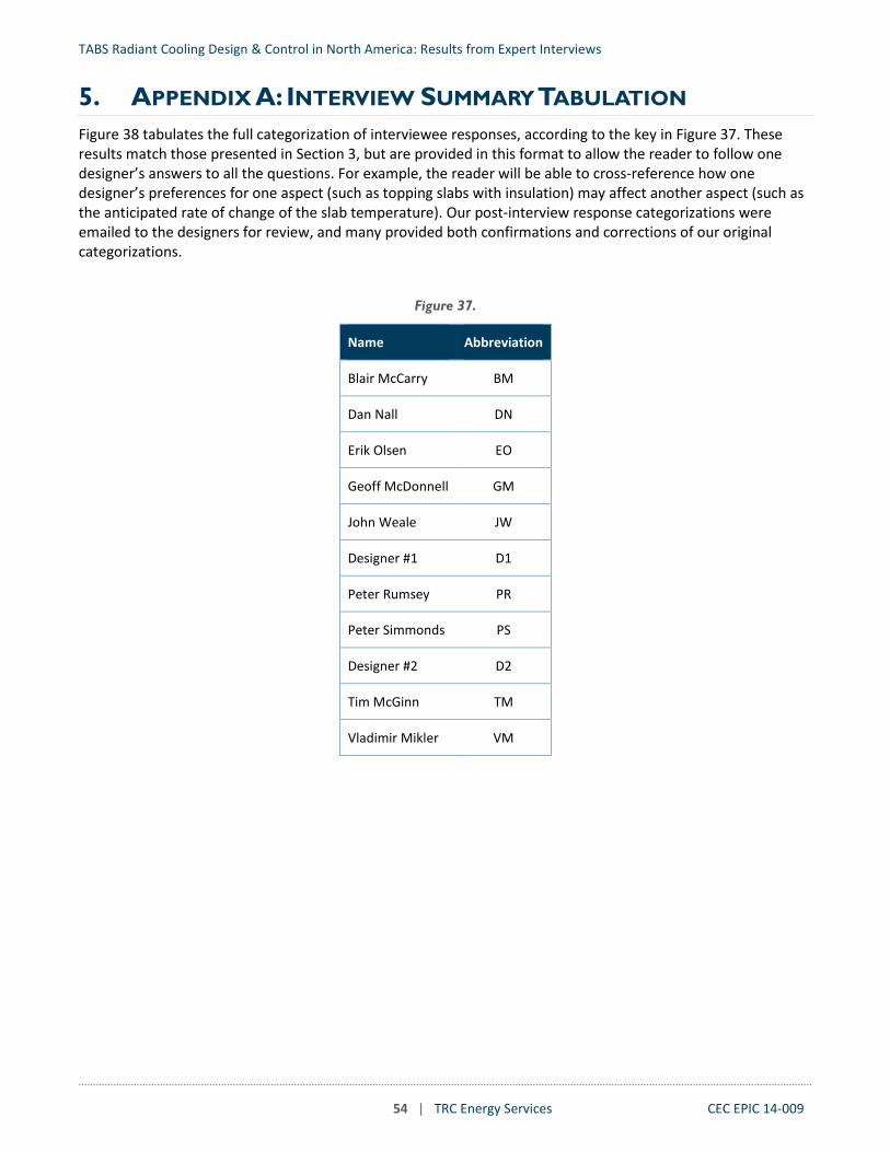
TABS Radiant Cooling Design & Control in North America: Results from Expert Interviews
54 | TRC Energy Services CEC EPIC 14-009
5. APPENDIX A: INTERVIEW SUMMARY TABULATION Figure 38 tabulates the full categorization of interviewee responses, according to the key in Figure 37. These results match those presented in Section 3, but are provided in this format to allow the reader to follow one designer’s answers to all the questions. For example, the reader will be able to cross-reference how one designer’s preferences for one aspect (such as topping slabs with insulation) may affect another aspect (such as the anticipated rate of change of the slab temperature). Our post-interview response categorizations were emailed to the designers for review, and many provided both confirmations and corrections of our original categorizations.
Figure 37.
Name Abbreviation
Blair McCarry BM
Dan Nall DN
Erik Olsen EO
Geoff McDonnell GM
John Weale JW
Designer #1 D1
Peter Rumsey PR
Peter Simmonds PS
Designer #2 D2
Tim McGinn TM
Vladimir Mikler VM

TABS Radiant Cooling Design & Control in North America: Results from Expert Interviews
55 | TRC Energy Services CEC EPIC 14-009
Figure 38.
Question Response
Response subcategory Count BM DN EO GM JW D1 PR PS D2 TM VM
What was your primary role on these projects?
Engineer of record, lead designer, or engineer 9 X X X X X X X X X Overseeing principal 3 X X X Consultant to architect 2 X X
How many radiant cooling projects have you worked on that were TABS?
1 to 5 2 X X
6 to 10 4 X X X X
11 to 20 1 X
More than 20 4 X X X X Where have your radiant cooling projects been installed?
United States - west coast 1 X
United states - other locations 3 X X X
Canada - west coast 4 X X X X Canada - other locations 1 X
United States, Canada, and International 4 X X X X In what building occupancy types are TABS most appropriate?
Radiant is appropriate for most occupancy types 7 X X X X X X X Radiant is most appropriate in large open areas such as lobbies, atrium, museums, and airport terminals. Also areas with large solar gains.
4 X X X X
Radiant is usually the predominant cooling strategy 7 X X X X X X X
Radiant is mainly only used in specific areas 3 X X X
Does your radiant design typically use tubing located in the structural slab or topping slab? Why?
Tubing located in structural slab 1 X
Tubing located in topping slab 5 X X X X X
Either is possible. 7 X X X X X X X Do you design the active radiant surface to be the floor, ceiling, or both?
Ceiling 2 X X
Floor 2 X X
Either, depending on application 6 X X X X X X Do you try limiting the mass of the active radiant surface, or is the mass determined by other considerations? How does the mass influence the radiant system design?
Amount of active mass is mainly determined by structural design 6 X X X X X X

TABS Radiant Cooling Design & Control in North America: Results from Expert Interviews
56 | TRC Energy Services CEC EPIC 14-009
Question Response
Response subcategory Count BM DN EO GM JW D1 PR PS D2 TM VM
Low mass topping slabs are used where quicker thermal response is desired 3 X X X
Do your radiant designs provide both cooling and heating?
TABS radiant systems are also used for heating (if there is a need for heating). 9 X X X X X X X X X
Alternate method is used for heating. 2 X X
Do you use higher chilled water temperatures than you would in typical air handling systems? What strategies do you use to generate the warmer water?
Conventional chiller plant 18
CHW for radiant generated at low temperature (mid 40s) then blended with return water from
radiant to achieve desired supply water temperature for radiant
8 X X X X X X X X
Separate CHW plants for low temperature uses (dehumidification, fan coils) and high
temperature uses (radiant) 7 X X X X X X X
CHW for radiant generated at higher temperature (50s and 60s), and alternate
method used for dehumidification (including passive means, or not needed)
3 X X X
Compressorless chilled water plant 4 X X X X
What space types need supplemental cooling to meet peak loads (in addition to the radiant slab?)
Most radiant spaces need supplemental cooling (via increased outside air or other method) 3 X X X
Some spaces need supplemental cooling due to high heat gains (e.g., conference rooms or south facing zones)
6 X X X X X X
Usually there is no need for supplemental cooling aside from ventilation air 3 X X X
What supplemental cooling systems do you use?
Fan coils, especially in areas with highly variable heat gains 4 X X X X
Radiant ceiling panels 3 X X X
Variable volume air handler with recirculation air 3 X X X
Adjust air handler volume, while staying above minimum ventilation rates 8
To whole building without zone dampers 2 X X
To zone, DOAS responds to total zone demands 6 X X X X X X
Adjust ventilation supply air temperature 8
At the air handler 7 X X X X X X X At the zone 1 X
What ventilation system do you pair with radiant systems?

TABS Radiant Cooling Design & Control in North America: Results from Expert Interviews
57 | TRC Energy Services CEC EPIC 14-009
Question Response
Response subcategory Count BM DN EO GM JW D1 PR PS D2 TM VM
Variable volume DOAS 13 X X X
Adjust volume to zone, DOAS responds to maintain static pressure 5 X X X X X
Adjust DOAS volume to entire building or floor plate 5 X X X X X
Constant volume DOAS 5 X X X X X Demand controlled ventilation 4 X X X X Natural ventilation 5 X X X X X Does the DOAS ventilation supply typically include heat recovery?
Usually 7 X X X X X X X Only occasionally 2 X X
How does the DOAS dehumidify outside air?
Dehumidification methods used 0
Chilled water 11 X X X X X X X X X X X DX 2 X X
Dessicant wheel 4 X X X X
Energy recovery 1 X
Radiant system is designed so as to not require dehumidification 3 X X X
Is the DOAS sized larger than minimum ventilation requirements?
DOAS is sized to meet ASHRAE 62.1 or local code 2 X X
DOAS is sized larger than minimum ventilation requirements 0
For LEED additional ventilation credit 6 X X X X X X
For supplemental cooling 8 X X X X X X X X Oversized DOAS is controlled to provide
economizer cooling 1 X
Do radiant system zones have different sizing constraints than other types of systems? Are they related to manifolds, loop length, or costs of zone valves?
Controlled zones are as large as possible (full floor plate, several manifolds, many loops) 4 X X X X
Zones are separated by orientation and/or exposure, generally with one zone per perimeter orientation (interior/exterior, multiple manifolds, several loops)
7 X X X X X X X
Zones are small (control valve for each individual manifold) 1 X
Zones are very small (individual loops) 1 X
How do you zone the radiant system in high occupancy spaces like conference rooms?
Conference room radiant supply are zoned independently 4 X X X X
Conference rooms radiant dupply are not zoned independently (large zones service conference rooms and other spaces)
4 X X X X

TABS Radiant Cooling Design & Control in North America: Results from Expert Interviews
58 | TRC Energy Services CEC EPIC 14-009
Question Response
Response subcategory Count BM DN EO GM JW D1 PR PS D2 TM VM
When ventilation systems are used for supplemental cooling, how do you zone them in comparison to radiant zones?
Ventilation zones align with radiant zones 1 X
Ventilation zones based on thermal requirements 4 X X X X
Ventilation zones based on ventilation requirements 5 X X X X X
Do you use valves or zone circulator pumps for zone control?
Valves are used for zone control 8 X X X X X X X X
Usually valves are used, but pumps are used occasionally 1 X
Pumps are used for zone controls 3 X X X Each zone is an isolated circuit with a pump and heat exchanger 1 X
Do your buildings allow different zones to be in heating and cooling at the same time (2-pipe systems versus 4 pipe systems)?
Whole building can only be in either heating or cooling (2-pipe systems) 6 X X X X X X
Heating and cooling are available at the same time in different areas of the building that contain multiple zones (4-pipe by orientation, by floor)
3 X X X
Heating and cooling are available at the same time in each zone (4-pipe to each zone) 3 X X X
Is the chilled water plant smaller for a radiant cooling system than it would be for an all-air system for the same building?
Size is the same as a low mass building served by air system 5 X X X X X
Size is smaller to account for high thermal mass 5 X X X X X Do you use ceiling fans with radiant? If so, how do they help?
Have not included ceiling fans in any radiant project 4 X X X X
Ceiling fans rarely included in some projects 5 X X X X X
Ceiling fans often used projects 2 X X
How do you control radiant zones -- by varying water flow, varying water temperature, or both? If you vary flow, is it achieved by modulation (modulating valves or variable speed pump) or on/off control (cycling pumps or 2-position valves)?
Two position zone valves 6 X
Valve open/close position responds to set point (control sequence not described) 3 X X X

TABS Radiant Cooling Design & Control in North America: Results from Expert Interviews
59 | TRC Energy Services CEC EPIC 14-009
Question Response
Response subcategory Count BM DN EO GM JW D1 PR PS D2 TM VM
Valve open/close position is pulse-time modulated to prevent short cycling and control
average capacity to maintain set point 2 X X
Modulating zone valves 4 X X X X
Pumps with 3-way control valves at the zone 3 X
Constant speed pump 1 X Variable speed pump 1 X
What is the set point temperature for the water/fluid entering the slab (in cooling mode)?
50 – 55 °F 1 X
55 – 60 °F 5 X X X X X
60 – 65 °F 4 X X X X
65 – 70 °F 1 X Is the slab fluid temperature controlled seasonally?
No 0
Yes 11
Adjusted actively on short time scale 1 X
Adjusted gradually throughout the year using trailing-average OAT 5 X X X X X
Adjusted gradually throughout the year using seasonal schedule 3 X X X
Controlled but remains nearly constant 2 X X
Is there a slab temperature sensor? If so, where do you locate it?
In between and at the same level as tubes 6 X X X X X X
Near surface of slab 3 X X X Infrared temperature measurement of slab surface 1 X
Is the slab temperature measured and controlled?
Slab temperature is measured but not controlled 1 X
Slab temperature is measured and controlled 12 X
Slab temperature set point is reset (OA reset, thermostat deviation from set point) 5 X X X X X
Slab temperature set point remains nearly constant 6 X X X X X X
What are the typical space temperature set points in heating? In cooling?
Space temperature setpoints are similar to conventional all air buildings 3 X X X
Space temperature setpoints have a wider deadband than conventional all air buildings 5 X X X X X
Does the radiant system operate outside of occupied hours? If so, how?

TABS Radiant Cooling Design & Control in North America: Results from Expert Interviews
60 | TRC Energy Services CEC EPIC 14-009
Question Response
Response subcategory Count BM DN EO GM JW D1 PR PS D2 TM VM
Radiant enabled at all times with constant space temperature set points during both occupied and unoccupied periods
4 X X X X
Radiant enabled at all times and space cooling temperature set point is increased during unoccupied periods
4 X X X X
Radiant disabled at night except to maintain set back temperature 2 X X
Do you often use the radiant slab for building pre-cooling? Are there issues or limitations? How do you limit overcooling?
Pre-cooling is not being used 6 X X X X X X
Have occasionally used pre-cooling 7 X
To operate plant in a more efficient way 3 X X X To reduce peak electrical demand 1 X
To reduce size of chiller 2 X X If radiant zones have supplemental cooling, (through the DOAS for example), how are they controlled? Do you interlock SOO and control loops or do they run independently? How?
Control loops for radiant slab and supplemental systems are completely independent 7 X X X X X X X
Control loops for radiant slab and supplemental systems are linked 5 X X X X X
How do you prevent fighting (heating/cooling simultaneously) with radiant and supplemental systems?
The controls are interlocked so that the slab and supplemental cooling are in the same mode (cooling/heating), and/or the slab is locked out or neutral when supplemental system mode changes occur.
5 X X X X X
There is no specific measure to prevent simultaneous heating and cooling 5 X X X X X
For systems with both radiant heating and cooling, how is the changeover from heating to cooling (and vice-versa) controlled on the radiant system (e.g. with a dead band)? How is the dead band determined? If you have 2-pipe to any group of sub-zones, how do you determine the mode for the group?
Force radiant slab to turn off 8 X
Time delay between heating and cooling 2 X X
Dead band or lockout between heating and cooling set points 5 X X X X X
Limit the rate of change 4
Slab temperature is reset to neutral before changing modes 1 X
Reset to neutral based on formula using a trailing average of outside air temperature (3-5
day average) 3 X X X
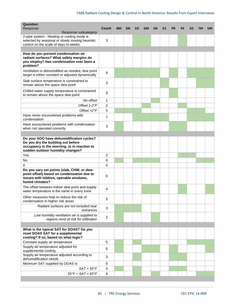
TABS Radiant Cooling Design & Control in North America: Results from Expert Interviews
61 | TRC Energy Services CEC EPIC 14-009
Question Response
Response subcategory Count BM DN EO GM JW D1 PR PS D2 TM VM
2-pipe system - Heating or cooling mode is selected by seasonal or slowly moving heuristic control on the scale of days to weeks.
3 X X X
How do you prevent condensation on radiant surfaces? What safety margins do you employ? Has condensation ever been a problem?
Ventilation is dehumidified as needed, dew point target is either constant or adjusted dynamically 9 X X X X X X X X X
Slab surface temperature is constrained to remain above the space dew point 3 X X X
Chilled water supply temperature is constrained to remain above the space dew point 9 X
No offset 1 X
Offset 1-2°F 2 X X
Offset >2°F 5 X X X X X
Have never encountered problems with condensation 7 X X X X X X X
Have encountered problems with condensation when not operated correctly 3 X X X
Do your SOO have dehumidification cycles? Do you dry the building out before occupancy in the morning, or in reaction to sudden outdoor humidity changes?
Yes 2 X X
No 6 X X X X X X 0 0
Do you vary set points (slab, CHW, or dew-point offset) based on condensation due to issues with lobbies, operable windows, humid climates?
0
The offset between indoor dew point and supply water temperature is the same in every zone 4 X X X X
Other measures help to reduce the risk of condensation in higher risk areas 5
Radiant surfaces are not included near entrances 3 X X X
Low humidity ventilation air is supplied to regions most at risk for infiltration 2 X X
What is the typical SAT for DOAS? Do you reset DOAS SAT for a supplemental cooling? If so, based on what logic?
Constant supply air temperature 5 X X X X X Supply air temperature adjusted for supplemental cooling 5 X X X X X
Supply air temperature adjusted according to dehumidification needs 3 X X X
Minimum SAT supplied by DOAS is 0
SAT < 55°F 4 X X X X
55°F < SAT < 65°F 4 X X X X

TABS Radiant Cooling Design & Control in North America: Results from Expert Interviews
62 | TRC Energy Services CEC EPIC 14-009
Question Response
Response subcategory Count BM DN EO GM JW D1 PR PS D2 TM VM
If DOAS is oversized, do you also reset airflow?
Ventilation airflow rate is constant 1 X
Ventilation airflow rate is adjusted for demand controlled ventilation 4 X X X X
Ventilation airflow rate is adjusted for supplemental cooling 6 X X X X X X