HVAC concepts for radiant cooling systems - …beepindia.org/sites/default/files/L4 - HVAC concepts...
16
HVAC concepts for radiant cooling systems Schematic principles 1
Transcript of HVAC concepts for radiant cooling systems - …beepindia.org/sites/default/files/L4 - HVAC concepts...

HVAC concepts for radiant
cooling systems
Schematic principles
1

2Indo-Swiss Building Energy Efficiency Project
1) «Conventional» design for radiant
cooling
• Hydronic design withfixed 6/12°C Chilledwater and mixing to 14-16 °C for the slab/panels
• Loss of the benefit of the higher COP with higherevaporation temperature
• Bypass on the demandside low differential, more power for pumps 2
C O N D E N S E U R
E V A P O R A T E U R
cooling pumps
2 way valve (no
bypass, variable
flow)
chilled water return
hydronic
connection with
bypass
Bypass (3 way valve)?
by-pass
constant set point
Constant flow rate
3Indo-Swiss Building Energy Efficiency Project
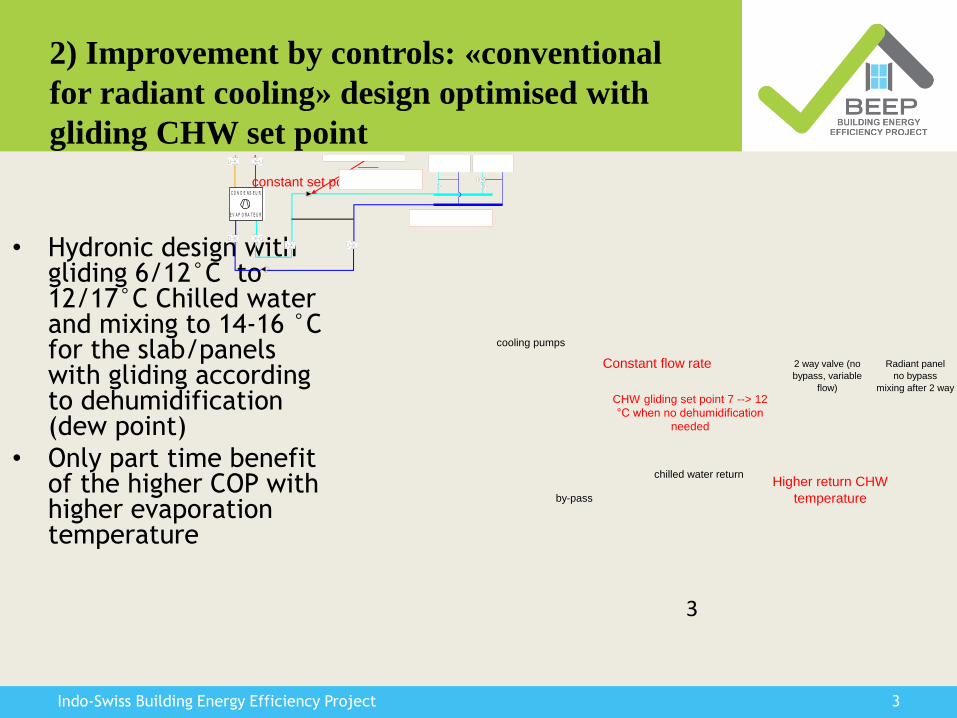
2) Improvement by controls: «conventional
for radiant cooling» design optimised with
gliding CHW set point
• Hydronic design withgliding 6/12°C to 12/17°C Chilled water and mixing to 14-16 °C for the slab/panels with gliding accordingto dehumidification(dew point)
• Only part time benefitof the higher COP withhigher evaporationtemperature
3
C O N D E N S E U R
E V A P O R A T E U R
cooling pumps
2 way valve (no
bypass, variable
flow)
chilled water return
Radiant panel
no bypass
mixing after 2 way
by-pass
constant set point
Constant flow rate
CHW gliding set point 7 --> 12
°C when no dehumidification
needed
Higher return CHW
temperature
4Indo-Swiss Building Energy Efficiency Project
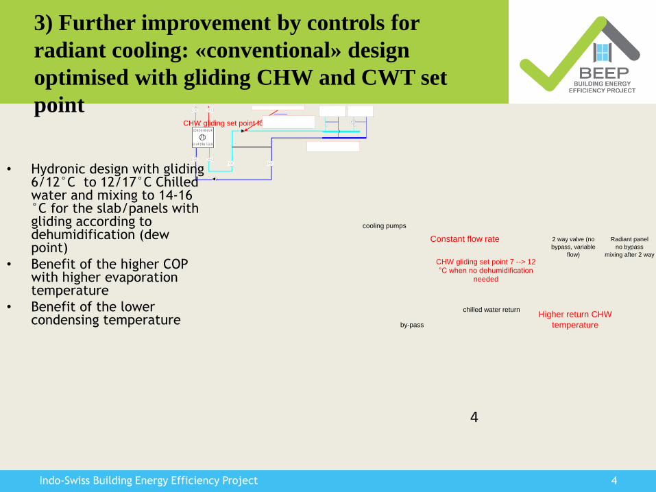
3) Further improvement by controls for
radiant cooling: «conventional» design
optimised with gliding CHW and CWT set
point
• Hydronic design with gliding6/12°C to 12/17°C Chilledwater and mixing to 14-16 °C for the slab/panels withgliding according to dehumidification (dewpoint)
• Benefit of the higher COP with higher evaporationtemperature
• Benefit of the lowercondensing temperature
4
C O N D E N S E U R
E V A P O R A T E U R
cooling pumps
2 way valve (no
bypass, variable
flow)
chilled water return
Radiant panel
no bypass
mixing after 2 way
by-pass
CHW gliding set point follow WB
Constant flow rate
CHW gliding set point 7 --> 12 °C when no dehumidification
needed
Higher return CHW
temperature

5Indo-Swiss Building Energy Efficiency Project
4) Further improvement by controls:
«conventional» design optimised with gliding
CHW and CWT set point and variable flow
• Hydronic design with gliding6/12°C to 12/17°C Chilledwater and mixing to 14-16 °C for the slab/panels withgliding according to dehumidification (dew point)
• Benefit of the higher COP withhigher evaporationtemperature
• Benefit of the lowercondensing temperature
• Less power for CHW and condensing water loop
5
C O N D E N S E U R
E V A P O R A T E U R
cooling pumps
2 way valve (no
bypass, variable
flow)
chilled water return
Radiant panel
no bypass
mixing after 2 way
by-pass
CHW gliding set point follow WB
Variable flow rate
CHW gliding set point 7 --> 12 °C when no dehumidification
needed
Higher return CHW
temperature

6Indo-Swiss Building Energy Efficiency Project
5) Improvement by design
• Separate chillersfor sensible and latent coolingloads– Main chiller for
sensible cooling• Higher CHW
temperature( 7°C 12-14°C)
• Higher COP
– Smaller chillerfor latent load• dehumidific
ation6
C O N D E N S E U R
E V A P O R A T E U R
cooling pumps
DOAS
cooling coil
chilled water return
Radiant panel
hydronic network
by-pass
CHW gliding set point follow WB
Variable flow rate
CHW gliding set point 12 --> 16
°C
Higher return CHW
temperature
C O N D E N S E U R
E V A P O R A T E U R
Main chiller (radiant cooling
hydronic)
Small chiller (DOAS)
CHW gliding set point 7 --> 12
°C when no dehumidification
needed

7Indo-Swiss Building Energy Efficiency Project
6) Improvement by design
• Separate chillers for sensible and latent cooling loads– Main chiller for
sensible cooling• Higher CHW
temperature( 7°C 12-14°C)
• Higher COP
– Smaller chiller for latent load
• Dehumidification
– Free-cooling for the radiant network (Northern India, …)
7
C O N D E N S E U R
E V A P O R A T E U R
cooling pumps
DOAS
cooling coil
chilled water return
Radiant panel
hydronic network
by-pass
CHW gliding set point follow WB
Variable flow rate
CHW gliding set point 12 --> 16
°C
Higher return CHW
temperature
C O N D E N S E U R
E V A P O R A T E U R
Main chiller (radiant cooling
hydronic)
Small chiller
(DOAS)
CHW gliding set point 7 --> 12
°C when no dehumidification
needed
8Indo-Swiss Building Energy Efficiency Project
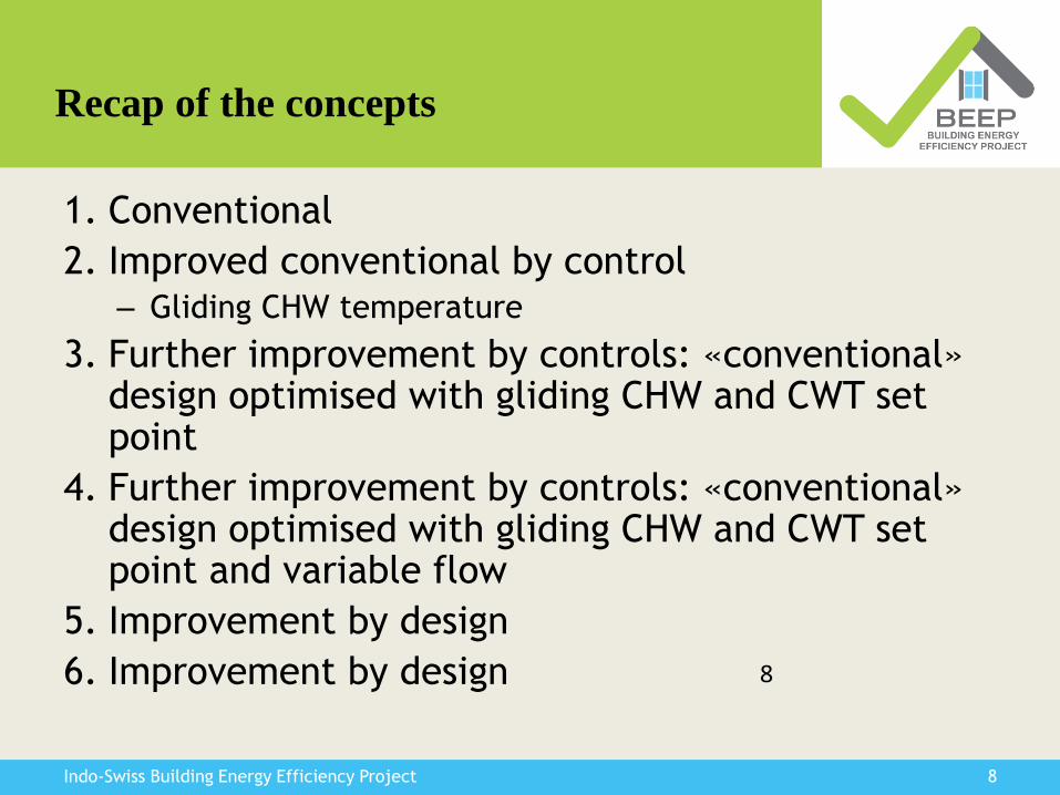
Recap of the concepts
1. Conventional
2. Improved conventional by control– Gliding CHW temperature
3. Further improvement by controls: «conventional» design optimised with gliding CHW and CWT set point
4. Further improvement by controls: «conventional» design optimised with gliding CHW and CWT set point and variable flow
5. Improvement by design
6. Improvement by design 8

9Indo-Swiss Building Energy Efficiency Project
Chillers performances (AHRI 550/90)
Influence of CHW temperature on COP
9
10Indo-Swiss Building Energy Efficiency Project
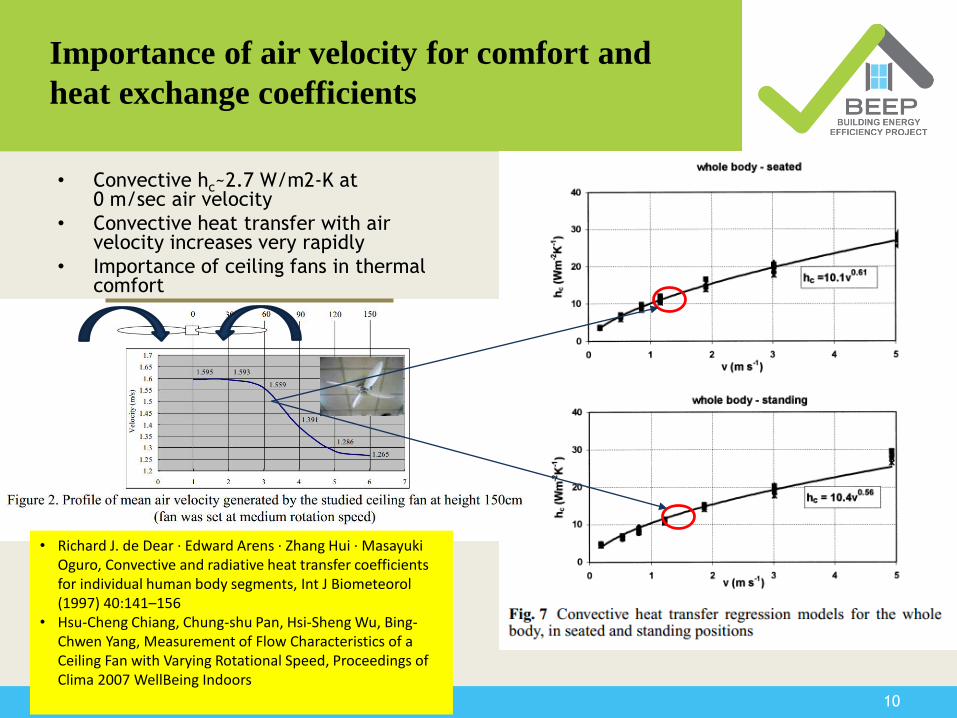
Importance of air velocity for comfort and
heat exchange coefficients
• Convective hc~2.7 W/m2-K at 0 m/sec air velocity
• Convective heat transfer with air velocity increases very rapidly
• Importance of ceiling fans in thermal comfort
• Richard J. de Dear · Edward Arens · Zhang Hui · Masayuki Oguro, Convective and radiative heat transfer coefficients for individual human body segments, Int J Biometeorol (1997) 40:141–156
• Hsu-Cheng Chiang, Chung-shu Pan, Hsi-Sheng Wu, Bing-Chwen Yang, Measurement of Flow Characteristics of a Ceiling Fan with Varying Rotational Speed, Proceedings of Clima 2007 WellBeing Indoors
11Indo-Swiss Building Energy Efficiency Project
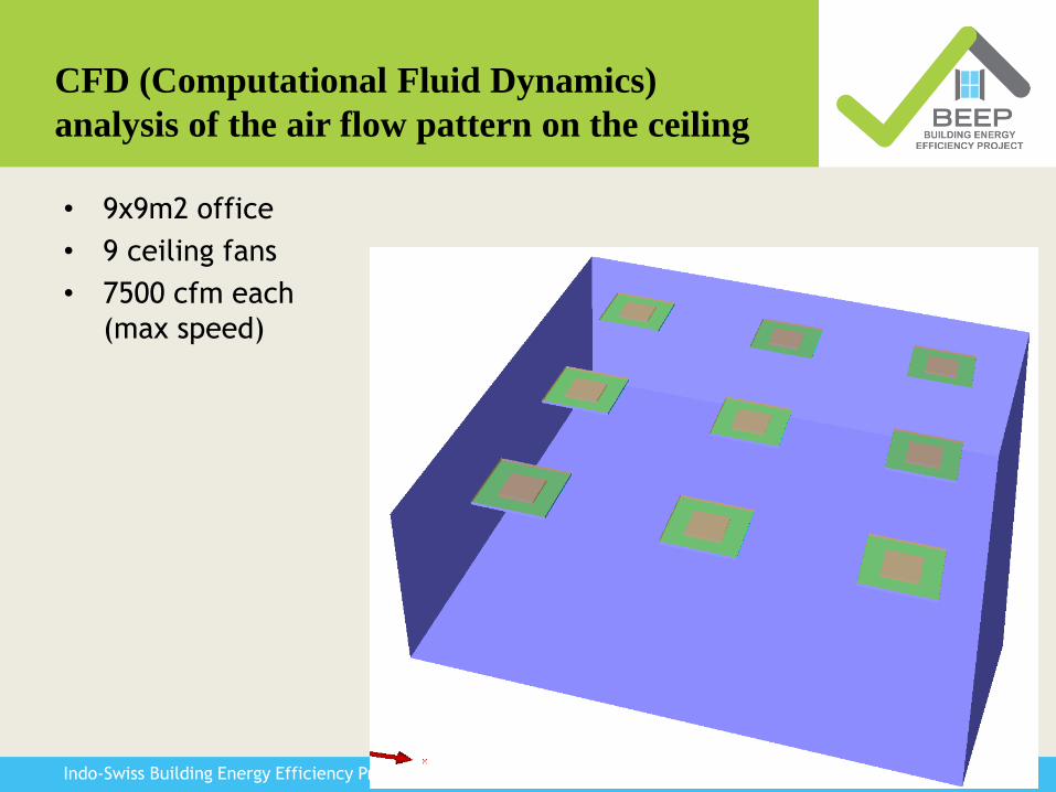
CFD (Computational Fluid Dynamics)
analysis of the air flow pattern on the ceiling
• 9x9m2 office
• 9 ceiling fans
• 7500 cfm each
(max speed)

12Indo-Swiss Building Energy Efficiency Project
• Velocity on the ceiling
13Indo-Swiss Building Energy Efficiency Project
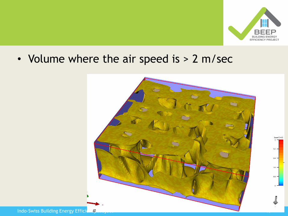
• Volume where the air speed is > 2 m/sec

14Indo-Swiss Building Energy Efficiency Project
Increase of the heat transfer at the
ceiling by the use of ceiling fans
• Increased heattransfer coefficient by air movement– Ceiling
– ~2.0 m/sec at ceilinglevel hc increased
from 2.8 to ~8.8 W/m2-K
– Hr+hconv ~ 13 W/m2-K
– COP of gained heattransfer ~> 8 withhigh efficiency fan

15Indo-Swiss Building Energy Efficiency Project
• Further studies needed on the topics and
integration in building simulation software
• Possible in TRNSYS (by using correlations)
• Other softwares ?

Click to edit
Master title style
Click to edit
Master title style
16Indo-Swiss Building Energy Efficiency Project
THANK YOU


![Radiant Floor Cooling Systems[1]](https://static.fdocuments.net/doc/165x107/5514c6bc497959f81d8b4975/radiant-floor-cooling-systems1.jpg)