Table of Contents - rexarcmanifolds.com · Table of Contents Page ... Breathing Air, Oxygen...
104
Transcript of Table of Contents - rexarcmanifolds.com · Table of Contents Page ... Breathing Air, Oxygen...


Table of ContentsPage
General Use of this Catalog . . . . . . . . . . . . . . . . . . . . . . . . . . . . . . . . . . . . . . . . . . . . . 4
Piping Systems for Welding Gases . . . . . . . . . . . . . . . . . . . . . . . . . . . . . . . . . . . . . . . . 5
Manifold Systems and Station Outlets
Fuel Gas Distribution Systems . . . . . . . . . . . . . . . . . . . . . . . . . . . . . . . . . . . . . . . . . . . . . 8
Hydrogen, Methane Distribution Systems w/Flashback Arresters . . . . . . . . . . . . . . . . . . . 13
Oxygen, Inert Gas Distribution Systems . . . . . . . . . . . . . . . . . . . . . . . . . . . . . . . . . . . . . . 18
4,500 psig Inlet Inert Gas Distribution Systems . . . . . . . . . . . . . . . . . . . . . . . . . . . . . . . . 29
Carbon Dioxide Distribution Systems . . . . . . . . . . . . . . . . . . . . . . . . . . . . . . . . . . . . . . . . 34
Heater for Carbon Dioxide Gas, 110 Volts . . . . . . . . . . . . . . . . . . . . . . . . . . . . . . . . . . . . 41
Helium, Hydrogen, Methane Manifolds w/o Flashback Arresters . . . . . . . . . . . . . . . . . . . . 42
Two Cylinder Discharging Manifolds . . . . . . . . . . . . . . . . . . . . . . . . . . . . . . . . . . . . . . . . . 48
Breathing Air, Oxygen Manifolds (Cascade Type) . . . . . . . . . . . . . . . . . . . . . . . . . . . . . . . 50
PalletMaster 639 Palletized Cylider Distribution System . . . . . . . . . . . . . . . . . . . . . . . . . . 52
Portable Distribution Systems . . . . . . . . . . . . . . . . . . . . . . . . . . . . . . . . . . . . . . . . . . . . . 53
Station Outlets . . . . . . . . . . . . . . . . . . . . . . . . . . . . . . . . . . . . . . . . . . . . . . . . . . . . . . . . . 54
Changeover Warning Systems . . . . . . . . . . . . . . . . . . . . . . . . . . . . . . . . . . . . . . . . . . . . . 59
Liquid Flashback Arresters and Relief Valves . . . . . . . . . . . . . . . . . . . . . . . . . . . . . . . . . . 65
Pressure and Flow Control Equipment
Cylinder Regulators, Single Stage . . . . . . . . . . . . . . . . . . . . . . . . . . . . . . . . . . . . . . . . . . 70
Station Regulators, Single Stage . . . . . . . . . . . . . . . . . . . . . . . . . . . . . . . . . . . . . . . . . . . 73
Line Regulators, Single Stage . . . . . . . . . . . . . . . . . . . . . . . . . . . . . . . . . . . . . . . . . . . . . 75
Cylinder Regulator-Flowmeters and Regulator-Flowgauges . . . . . . . . . . . . . . . . . . . . . . . 77
Station Flowmeters . . . . . . . . . . . . . . . . . . . . . . . . . . . . . . . . . . . . . . . . . . . . . . . . . . . . . 80
Special Application Regulators . . . . . . . . . . . . . . . . . . . . . . . . . . . . . . . . . . . . . . . . . . .8 82
Accessories
In-line Ball Valves, In-line Check Valves and Labels . . . . . . . . . . . . . . . . . . . . . . . . . . . . . 87
Elbows, Extensions, Cylinder Racks, Cylinder Pigtails, and CGA Fittings . . . . . . . . . . . . . 93
Specialty Hand Torches and the Gas Economizer . . . . . . . . . . . . . . . . . . . . . . . . . . . . 98
Rexarc Warranty . . . . . . . . . . . . . . . . . . . . . . . . . . . . . . . . . . . . . . . . . . . . . . . . . . . . . . 103
© 2010 Rexarc International, Inc. – All rights reserved.

Thank you for choosing Rexarc for your industrial gas distribution needs. All Rexarc gas distribution systems in thiscatalog come complete as a system with single part numberidentifying a family of properly engineered components specific for your application.
The first part of the system part numbers designate the typeof system operation. There are two basic sets of numbers forRexarc distribution systems:
3-04 Manual System – Manual changeover is required andslight interruption may occur for equipment attached to thedownstream piping system.
4-04 Automatic System – Changeover is automatic and supplyis uninterrupted for equipment attached to the downstreampiping system.
There is a series of letters contained in a Rexarc gas distribution system part number to designate certain systemcharacteristics. Below are the various letters and what systemfeatures are assigned to each letter:
F Wall mount system with liquid flashback arrester
J Floor Mount system with liquid flashback arrester
H Heater is included with system (Carbon Dioxide, Nitrous Oxide)
S Stand is included for system floor mounting
V Vaporizer
HP High Pressure: System delivery up to 200 psi
SHP System stand and high pressure delivery (Up to 200 psi)
To make ordering and technical support as straightforward as possible, our gas distribution system part numbers containan identifier to indicate the type of gas to be used with thesystem. Below are the various gases and the letter associatedwith that gas when talking to Rexarc.
R Acetylene
G Oxygen
N Nitrogen
HY Hydrogen
A Argon
C Carbon Dioxide
AC Argon/Carbon Dioxide
HE Helium
PE Propylene Based Gases
MA MAPP
BA Breathing Air
IA Industrial Air
CA Compressed Air
ME Methane
NG Natural Gas
Y LPG Type Gases
The last number in a Rexarc system part number designatesthe total number of cylinders in a system. Depending on thestyle and type of distribution system, the number may varyslightly but the general rule is that the last number representsthe total number of cylinders in the system.
For example, a six cylinder system will have a "- 6" at the end of the part number. For a twin header or an automaticdistribution system, this means that the distribution system
will have provisions for three cylinders on the left side andthree cylinders on the right side. If the system is a manual,single header, single regulator system, the "- 6" would indicatethat there are six total cylinders on the one system bank.
A sample part number is shown at the bottom of this page,showing what each portion of the part number represents:
Please use this page to assist you when selecting the properdistribution system for your application.
Once you familiarize yourself with our system numberingbasics, we hope you will find the Rexarc numbering systemeasy to use and will continue to choose Rexarc for all of yourgas distribution system needs.
If you don’t see what you need in this catalog but have adesign or idea for what you want in a system, just give us acall toll free at 1-877-Rexarc1 (877-739-2721) and ask oneof our system design specialists to configure a custom
“Build Your Own” system for your application.
Thank you again for choosing Rexarc.
General Use of this Catalog
4 - 0 4 - 0 1 4 7 S G - 6
System Type(Automatic
Changeover)
Series(Oxygen/Inert;
AutomaticChangeover)
Gas(Oxygen)
Cylinders(6 total)
Features(Stand/Floor
Mount)
4

General
Protective equipment is required in fuel gas and oxygen pip-ing systems to prevent a reverse flow of oxygen from flowingback up the fuel gas line, or a reverse flow of fuel gas fromflowing back up the oxygen line, also to prevent excessivepressure build-up in the system and stop a flashback fromreaching the supply source.
Piping systems shown comply to National Fire ProtectionAssociation Bulletin #51. Copies can be obtained by writing:
National Fire Protection Association, Inc.,1 Batterymarch Park, Quincy, MA 02169Phone: 1-800-344-3555Web Site: http://www.nfpa.org/catalog/
Piping Systemsfor Welding Gases
5

15 to 30 psig operating pressure
Pipe Sizing Chart for gas distribution systems Service piping: To assure adequate flow rates, it is most important to select the correct pipe size for the main supply and branchlines of your in-plant gas distribution system. The National Fire Protection Association in its Bulletin NFPA #51 (1992) outlinesstandards for the installation and operation of oxygen/fuel gas systems for welding and cutting. Copies can be obtained by writ-ing National Fire Protection Association, Inc., Batterymarch Park, Quincy, MA 02269.
Standard Length of pipe — Lineal FeetCubic Ft.Per Hour 50 100 250 500 750 1000 1250 1500 2000
100 3/4” 3/4” 1” 1” 1” 1” 1-1/4” 1-1/4” 1-1/4”200 3/4” 1” 1” 1-1/4” 1-1/4” 1-1/4” 1-1/2” 1-1/2” 1-1/2”300 1” 1” 1-1/4” 1-1/4” 1-1/2” 1-1/2” 1-1/2” 1-1/2” 1-1/2”400 1” 1-1/4” 1-1/4” 1-1/2” 1-1/2” 1-1/2” 2” 2” 2”500 1-1/4” 1-1/4” 1-1/2” 2” 2” 2” 2” 2” 2-1/2”750 1-1/4” 1-1/2” 1-1/2” 2” 2” 2-1/2” 2-1/2” 2-1/2” 2-1/2”
1000 1-1/2” 1-1/2” 2” 2-1/2” 2-1/2” 2-1/2” 2-1/2” 2-1/2” 3”1250 1-1/2” 1-1/2” 2” 2-1/2” 2-1/2” 2-1/2” 3” 3” 3”1500 1-1/2” 2” 2” 2-1/2” 3” 3” 3” 3” 3-1/2”1750 1-1/2” 2” 2-1/2” 2-1/2” 3” 3” 3” 3-1/2” 3-1/2”2000 2” 2” 2-1/2” 3” 3” 3” 3-1/2” 3-1/2” 3-1/2”2500 2” 2-1/2” 2-1/2” 3” 3-1/2” 3-1/2” 3-1/2” 3-1/2” 3-1/2”3000 2” 2-1/2” 3” 3-1/2” 3-1/2” 3-1/2” 3-1/2” 4” 4”3500 2-1/2” 2-1/2” 3” 3-1/2” 3-1/2” 3-1/2” 4” 4” 4”
30 to 50 psig operating pressure
Standard Length of pipe — Lineal FeetCubic Ft.Per Hour 50 100 250 500 750 1000 1250 1500 2000
100 3/4” 3/4” 3/4” 3/4” 3/4” 3/4” 3/4” 3/4” 3/4”200 3/4” 3/4” 3/4” 3/4” 3/4” 1” 1” 1” 1”300 3/4” 3/4” 3/4” 1” 1” 1” 1” 1” 1”400 3/4” 3/4” 1” 1” 1” 1-1/4” 1-1/4” 1-1/4” 1-1/4”500 3/4” 3/4” 1” 1” 1-1/4” 1-1/4” 1-1/4” 1-1/4” 1-1/4”750 3/4” 1” 1-1/4” 1-1/4” 1-1/4” 1-1/2” 1-1/2” 1-1/2” 1-1/2”
1000 1” 1” 1-1/4” 1-1/4” 1-1/2” 1-1/2” 1-1/2” 1-1/2” 1-1/2”1250 1” 1-1/4” 1-1/4” 1-1/2” 1-1/2” 2” 2” 2” 2”1500 1” 1-1/4” 1-1/2” 1-1/2” 2” 2” 2” 2” 2”1750 1-1/4” 1-1/4” 1-1/2” 2” 2” 2” 2” 2” 2”2000 1-1/4” 1-1/4” 1-1/2” 2” 2” 2” 2-1/2” 2-1/2” 2-1/2”2500 1-1/2” 1-1/2” 2” 2” 2” 2-1/2” 2-1/2” 2-1/2” 2-1/2”3000 1-1/2” 1-1/2” 2” 2” 2-1/2” 2-1/2” 2-1/2” 2-1/2” 2-1/2”3500 1-1/2” 1-1/2” 2” 2-1/2” 2-1/2” 2-1/2” 3” 3” 3”
50 to 100 psig operating pressure
Standard Length of pipe — Lineal FeetCubic Ft.Per Hour 50 100 250 500 750 1000 1250 1500 2000
100 1/2” 1/2” 1/2” 1/2” 1/2” 1/2” 1/2” 3/4” 3/4”200 1/2” 1/2” 1/2” 3/4” 3/4” 3/4” 3/4” 1” 1”300 1/2” 1/2” 3/4” 3/4” 3/4” 1” 1” 1-1/4” 1-1/4”400 3/4” 3/4” 3/4” 1” 1” 1” 1” 1-1/4” 1-1/4”500 3/4” 3/4” 3/4” 1” 1” 1” 1-1/4” 1-1/4” 1-1/4”750 3/4” 3/4” 1” 1-1/4” 1-1/4” 1-1/4” 1-1/4” 1-1/2” 1-1/2”
1000 3/4” 1” 1” 1-1/4” 1-1/4” 1-1/4” 1-1/2” 2” 2”1250 1” 1” 1-1/4” 1-1/4” 1-1/2” 1-1/2” 1-1/2” 2” 2”1500 1” 1” 1-1/4” 1-1/4” 1-1/2” 1-1/2” 2” 2” 2”1750 1” 1-1/4” 1-1/4” 1-1/2” 1-1/2” 2” 2” 2” 2-1/2”2000 1” 1-1/4” 1-1/4” 1-1/2” 2” 2” 2” 2-1/2” 2-1/2”2500 1-1/4” 1-1/4” 1-1/2” 2” 2” 2” 2” 2-1/2” 3”3000 1-1/4” 1-1/4” 1-1/2” 2” 2” 2” 2-1/2” 3” 3”3500 1-1/4” 1-1/2” 2” 2” 2” 2-1/2” 2-1/2” 3” 3”
6

Fuel gas branch lines under 2”
Fuel gas branch lines 2” or over
No pipe size restriction on branch lines, with torch station liquid flashback arresters
Oxygen and Fuel gasStation Outlet
Vent PipeFuel Gas and OxygenBranch Lines
Oxygen Relief Valve
Shutoff Valves
Liquid Flashback Arrester PF
Relief Valve
Main Fuel Gas andOxygen Supply Line
Oxygen and Fuel gasStation Outlet
Vent Pipe Fuel Gas and OxygenBranch Lines
Oxygen Relief Valve
Liquid Flashback Arrester PF Liquid Flashback Arrester PF
Relief ValveRelief Valve
Main Fuel Gas andOxygen Supply Line
Vent Pipe
Shutoff Valves
Shutoff Valves
Vent Pipe
Fuel Gas andOxygen Branch Lines
Oxygen Relief Valve
Liquid Flashback Arresterwith Relief Valve PF
Main Fuel Gas andOxygen Supply Line
Fuel Gas andOxygen Branch Lines
Oxygen Station Outlet
Vent Pipe
7

Rexarc manifold systems reduce cylinder handling costsand provide maximum safety.
Rexarc manifold systems allow better cylinder control, safetyand performance in your production facility while reducingcosts.
No more cylinders scattered about the workplace, thus savingtime in replacing empties while reducing rental costs andrecord keeping.
Safety is improved with the tighter cylinder control enabled bymanifold use, and production is positively impacted by elimi-nating frequent downtime due to cylinder change-outs.Gas consumption is also reduced since each cylinder is uni-formly emptied.
Selecting the correct size acetylene manifold
To select the proper acetylene manifold for your operation, con-sider these points:
1. Calculate the flow (scfh) at each use point in the piping sys-tem. Add the cubic feet per hour flow rate of each. The totalwill give you the volume of fuel gas needed per hour.
2. The manifold should have enough cylinders to provide for atleast one week’s fuel gas requirements.
3. Acetylene withdrawalsfor continuous opera-tion is 1/10th of thecylinder content perhour.
No. of Withdrawal Rate Per HourCylinders 145 Cu. Ft. 250 Cu. Ft. 300 Cu. Ft. 400 Cu. Ft.
Per Manifold Cylinder Cylinder Cylinder Cylinder
1 14 25 30 40
2 29 50 60 80
3 43 75 90 120
4 58 100 120 160
5 72 125 150 200
6 87 150 180 240
7 101 175 210 280
8 116 200 240 320
9 130 225 270 360
10 145 250 300 400
12 174 300 360 480
14 203 350 420 560
16 232 400 480 640
18 261 450 560 720
20 290 500 600 800
Fuel GasDistributionSystems
8

9
*Specify cylinder connections for acetylene (CGA 510 POL or CGA 300 Commercial)**Specify gas by name
• Maximum flow rate:Acetylene – 250 scfh @ 13 psigLPG Type – 250 scfh @ 35 psig
• Manifold switches automatically from “in-use” to “reserve” bank.
• Changeover warning system is not included. If a changeoverwarning system is desired, an explosion-proof pressure switch kitmust be ordered separately. See page 62.
Fuel Gas –Automatic Changeover, Wall Mount
Approx.No. Part No. ShippingCyl. Acetylene* LPG Type Gas** Length Wt. Lbs.
4 4-04-0136FR-CGA-4 4-04-0136FY-CGA-4 5’-5” 150
6 4-04-0136FR-CGA-6 4-04-0136FY-CGA-6 7’-7” 155
8 4-04-0136FR-CGA-8 4-04-0136FY-CGA-8 9’-9” 160
10 4-04-0136FR-CGA-10 4-04-0136FY-CGA-10 11’-11” 165
12 4-04-0136FR-CGA-12 4-04-0136FY-CGA-12 14’-1” 170
14 4-04-0136FR-CGA-14 4-04-0136FY-CGA-14 16’-3” 175
16 4-04-0136FR-CGA-16 4-04-0136FY-CGA-16 18’-5” 180
Fuel Gas – Automatic Changeover,Floor Mount, Cross Type
Approx.No. Part No. ShippingCyl. Acetylene* LPG Type Gas** Length Wt. Lbs.
8 4-04-0136JR-CGA-8 4-04-0136JY-CGA-8 5’-5” 185
12 4-04-0136JR-CGA-12 4-04-0136JY-CGA-12 7’-7” 195
16 4-04-0136JR-CGA-16 4-04-0136JY-CGA-16 9’-9” 205

10
Fuel Gas – Twin Regulator,Automatic Changeover, Wall Mount
Approx.No. Part No. ShippingCyl. Acetylene* LPG Type Gas** Length Wt. Lbs.
4 4-04-0125R-CGA-4 4-04-0125Y-CGA-4 8’-3” 337
6 4-04-0125R-CGA-6 4-04-0125Y-CGA-6 10’-5” 352
8 4-04-0125R-CGA-8 4-04-0125Y-CGA-8 12’-7” 367
10 4-04-0125R-CGA-10 4-04-0125Y-CGA-10 14’-9” 382
12 4-04-0125R-CGA-12 4-04-0125Y-CGA-12 16’-11” 397
14 4-04-0125R-CGA-14 4-04-0125Y-CGA-14 19’-11” 412
16 4-04-0125R-CGA-16 4-04-0125Y-CGA-16 21’-3” 427
18 4-04-0125R-CGA-18 4-04-0125Y-CGA-18 23’-5” 442
20 4-04-0125R-CGA-20 4-04-0125Y-CGA-20 25’-7” 457
*Specify cylinder connections for acetylene (CGA 510 POL or CGA 300 Commercial)**Specify gas by name
• Maximum flow rate:Acetylene – 1000 scfh @ 13 psigLPG Type – 1000 scfh @ 35 psig
• Manifold switches automatically from “in-use” to “reserve” bank.
• Changeover warning system is not included. If a changeoverwarning system is desired, an explosion-proof pressure switch kitmust be ordered separately. See page 62.
Fuel Gas – Twin Regulator, AutomaticChangeover, Floor Mount, Cross Type
Approx.No. Part No. ShippingCyl. Acetylene* LPG Type Gas** Length Wt. Lbs.
8 4-04-0126R-CGA-8 4-04-0126Y-CGA-8 8’-3” 337
12 4-04-0126R-CGA-12 4-04-0126Y-CGA-12 10’-5” 352
16 4-04-0126R-CGA-16 4-04-0126Y-CGA-16 12’-7” 367
20 4-04-0126R-CGA-20 4-04-0126Y-CGA-20 14’-9” 382

11
Fuel Gas – Single Regulator,Twin Header, Floor Mount, Cross Type
Approx.No. Part No. ShippingCyl. Acetylene* LPG Type Gas** Length Wt. Lbs.
8 3-04-0548R-CGA-8 3-04-0548Y-CGA-8 6’-9” 302
12 3-04-0548R-CGA-12 3-04-0548Y-CGA-12 8’-11” 317
16 3-04-0548R-CGA-16 3-04-0548Y-CGA-16 11’-1” 332
20 3-04-0548R-CGA-20 3-04-0548Y-CGA-20 13’-13” 347
*Specify cylinder connections for acetylene (CGA 510 POL or CGA 300 Commercial)**Specify gas by name
• Maximum flow rate:
8 to 16 cylindersAcetylene – 300 scfh @ 13 psigLPG Type – 300 scfh @ 35 psig
20 cylindersAcetylene – 1000 scfh @ 13 psigLPG Type – 1000 scfh @ 35 psig
• Manual changeover required to switch from “in-use” bank to“reserve” bank.
• Changeover warning system is not included. If a changeoverwarning system is desired, an explosion-proof pressure switch kitmust be ordered separately. See page 62.
Fuel Gas – Single Regulator,Twin Header, Wall Mount
Approx.No. Part No. ShippingCyl. Acetylene* LPG Type Gas** Length Wt. Lbs.
4 3-04-0546R-CGA-4 3-04-0546Y-CGA-4 6’-9” 302
6 3-04-0546R-CGA-6 3-04-0546Y-CGA-6 8’-11” 317
8 3-04-0546R-CGA-8 3-04-0546Y-CGA-8 11’-1” 332
10 3-04-0546R-CGA-10 3-04-0546Y-CGA-10 13’-13” 347
12 3-04-0546R-CGA-12 3-04-0546Y-CGA-12 15’-5” 362
14 3-04-0546R-CGA-14 3-04-0546Y-CGA-14 17’-7” 377
16 3-04-0546R-CGA-16 3-04-0546Y-CGA-16 19’-9” 392
18 3-04-0546R-CGA-18 3-04-0546Y-CGA-18 21’-11” 407
20 3-04-0546R-CGA-20 3-04-0546Y-CGA-20 24’-1” 422
*Specify cylinder connections for acetylene (CGA 510 POL or CGA 300 Commercial)**Specify gas by name
• Maximum flow rate:
4 to 16 cylindersAcetylene – 300 scfh @ 13 psigLPG Type – 300 scfh @ 35 psig
18 to 20 cylindersAcetylene – 1000 scfh @ 13 psigLPG Type – 1000 scfh @ 35 psig
• Manual changeover required to switch from “in-use” bank to“reserve” bank.
• Changeover warning system is not included. If a changeoverwarning system is desired, an explosion-proof pressure switch kitmust be ordered separately. See page 62.

12
Fuel Gas – Single Regulator,Single Header, Wall Mount
Approx.No. Part No. ShippingCyl. Acetylene* LPG Type Gas** Length Wt. Lbs.
2 3-04-0545R-CGA-2 3-04-0545Y-CGA-2 3’-8” 212
3 3-04-0545R-CGA-3 3-04-0545Y-CGA-3 4’-9” 223
4 3-04-0545R-CGA-4 3-04-0545Y-CGA-4 5’-10” 223
5 3-04-0545R-CGA-5 3-04-0545Y-CGA-5 6’-11” 243
6 3-04-0545R-CGA-6 3-04-0545Y-CGA-6 8’-0” 253
7 3-04-0545R-CGA-7 3-04-0545Y-CGA-7 9’-1” 263
8 3-04-0545R-CGA-8 3-04-0545Y-CGA-8 10’-2” 272
9 3-04-0545R-CGA-9 3-04-0545Y-CGA-9 11’-3” 280
10 3-04-0545R-CGA-10 3-04-0545Y-CGA-10 12’-4” 290*Specify cylinder connections for acetylene (CGA 510 POL or CGA 300 Commercial)
**Specify gas by name• Maximum flow rate:
2 to 8 cylindersAcetylene – 300 scfh @ 13 psigLPG Type – 300 scfh @ 35 psig
9 to 10 cylindersAcetylene – 1000 scfh @ 13 psigLPG Type – 1000 scfh @ 35 psig
• Temporary shutdown is required for cylinder changing.
• Changeover warning system is not included. If a changeoverwarning system is desired, an explosion-proof pressure switch kitmust be ordered separately. See page 62.
Fuel Gas – Single Regulator,Single Header, Floor Mount, Cross Type
Approx.No. Part No. ShippingCyl. Acetylene* LPG Type Gas** Length Wt. Lbs.
4 3-04-0547R-CGA-4 3-04-0547Y-CGA-4 3’-8” 228
6 3-04-0547R-CGA-6 3-04-0547Y-CGA-6 4’-9” 248
8 3-04-0547R-CGA-8 3-04-0547Y-CGA-8 5’-10” 264
10 3-04-0547R-CGA-10 3-04-0547Y-CGA-10 6’-11” 284*Specify cylinder connections for acetylene (CGA 510 POL or CGA 300 Commercial)
**Specify gas by name• Maximum flow rate:
4 to 8 cylindersAcetylene – 300 scfh @ 13 psigLPG Type – 300 scfh @ 35 psig
10 cylindersAcetylene – 1000 scfh @ 13 psigLPG Type – 1000 scfh @ 35 psig
• Temporary shutdown is required for cylinder changing.
• Changeover warning system is not included. If a changeoverwarning system is desired, an explosion-proof pressure switch kitmust be ordered separately. See page 62.

13
Rexarc manifold systems reduce cylinder handling costsand provide maximum safety.
Rexarc manifold systems allow better cylinder control, safetyand performance in your production facility while reducingcosts.
No more cylinders scattered about the workplace, thus savingtime in replacing empties while reducing rental costs andrecord keeping.
Safety is improved with the tighter cylinder control enabled bymanifold use, and production is positively impacted by elimi-nating frequent downtime due to cylinder change-outs.
Gas consumption is also reduced since each cylinder is uni-formly emptied.
Description
Rexarc hydraulic flashback arresters are required when hydro-gen, methane is used in conjunction with oxygen or com-pressed air.
Convoluted stainless steel cylinder pigtails are used due to thespecific gravity of the gases.
Rexarc hydrogen, methane distribution systems comply toNational Fire Protection Association Bulletin #51.
Selecting the correct size hydrogen, methane manifold:
1. Calculate the flow (scfh) at each use point in the piping sys-tem. Add the cubic feet per hour flow rate of each. The totalwill give you the volume of Hydrogen, Methane needed perhour.
2. The manifold should have enough cylinders to provide for atleast one week’s fuel gas requirements.
Hydrogen, MethaneDistribution Systemswith Flashback Arresters
14
Hydrogen, Methane – Automatic Changeover,Floor Mount, Cross Type
Hydrogen, Methane –Automatic Changeover, Wall Mount
• Maximum flow rate: 250 scfh @ 35 psig
• Manifold switches automatically from “in-use” to “reserve” bank.
• Manifold is supplied with 24” convoluted pigtails
• Changeover warning system is not included. If a changeoverwarning system is desired, an explosion-proof pressure switch kitmust be ordered separately. See page 62.
• Maximum flow rate: 250 scfh @ 35 psig
• Manifold switches automatically from “in-use” to “reserve” bank.
* Manifold is supplied with 24” convoluted pigtails
• Changeover warning system is not included. If a changeoverwarning system is desired, an explosion-proof pressure switch kitmust be ordered separately. See page 62.
Approx.No. Part No. ShippingCyl. Hydrogen Methane Length Wt. Lbs.
2 4-04-0136FHY-2 4-04-0136FME-2 3’-3” 140
4 4-04-0136FHY-4 4-04-0136FME-4 5’-5” 150
6 4-04-0136FHY-6 4-04-0136FME-6 7’-7” 155
8 4-04-0136FHY-8 4-04-0136FME-8 9’-9” 160
10 4-04-0136FHY-10 4-04-0136FME-10 11’-11” 165
12 4-04-0136FHY-12 4-04-0136FME-12 14’-1” 170
14 4-04-0136FHY-14 4-04-0136FME-14 16’-3” 175
16 4-04-0136FHY-16 4-04-0136FME-16 18’-5” 180
Approx.No. Part No. ShippingCyl. Hydrogen Methane Length Wt. Lbs.
8 4-04-0136JHY-8 4-04-0136JME-8 5’-5” 185
12 4-04-0136JHY-12 4-04-0136JME-12 7’-7” 195
16 4-04-0136JHY-16 4-04-0136JME-16 9’-9” 205

15
• Maximum flow rate: 1000 scfh @ 35 psig
• Manifold switches automatically from “in-use” to “reserve” bank.
• Manifold is supplied with 24” convoluted pigtails
• Changeover warning system is not included. If a changeoverwarning system is desired, an explosion-proof pressure switch kitmust be ordered separately. See page 62.
Hydrogen, Methane – Twin Regulator,Automatic Changeover, Wall Mount
Approx.No. Part No. ShippingCyl. Hydrogen Methane Length Wt. Lbs.
4 4-04-0095HY-4 4-04-0095ME-4 5’-10” 337
6 4-04-0095HY-6 4-04-0095ME-6 7’-6” 352
8 4-04-0095HY-8 4-04-0095ME-8 9’-2” 367
10 4-04-0095HY-10 4-04-0095ME-10 10’-10” 382
12 4-04-0095HY-12 4-04-0095ME-12 12’-6” 397
14 4-04-0095HY-14 4-04-0095ME-14 14’-2” 412
16 4-04-0095HY-16 4-04-0095ME-16 15’-10” 427
18 4-04-0095HY-18 4-04-0095ME-18 17’-6” 442
20 4-04-0095HY-20 4-04-0095ME-20 19’-2” 457
• Maximum flow rate: 1000 scfh @ 35 psig
• Manifold switches automatically from “in-use” to “reserve” bank.
• Manifold is supplied with 24” convoluted pigtails
• Changeover warning system is not included. If a changeoverwarning system is desired, an explosion-proof pressure switch kitmust be ordered separately. See page 62.
Hydrogen, Methane – Twin Regulator, Auto-matic Changeover, Floor Mount, Cross Type
Approx.No. Part No. ShippingCyl. Hydrogen Methane Length Wt. Lbs.
8 4-04-0097HY-8 4-04-0097ME-8 5’-0” 377
12 4-04-0097HY-12 4-04-0097ME-12 6’-8” 407
16 4-04-0097HY-16 4-04-0097ME-16 8’-4” 437
20 4-04-0097HY-20 4-04-0097ME-20 10’-0” 467
16
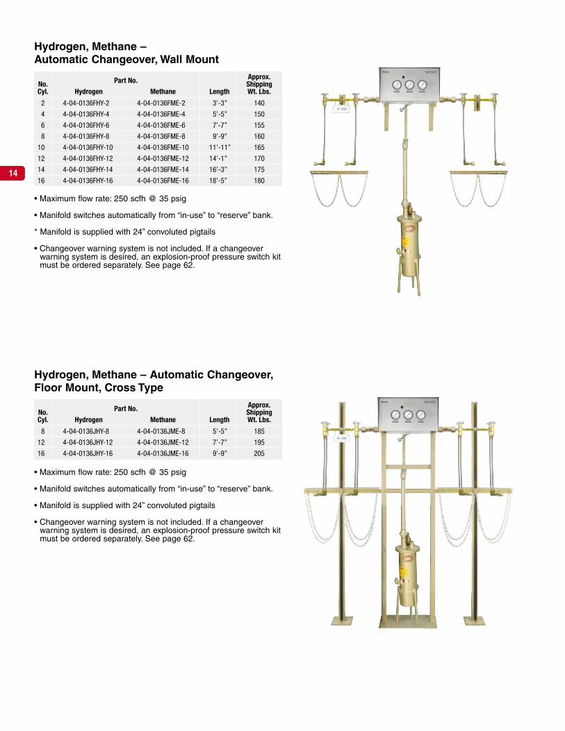
• Maximum flow rate:
8 to 16 cylinders – 300 scfh @ 35 psig
20 cylinders – 1000 scfh @ 35 psig
• Manual changeover required to switch from “in-use” bank to“reserve” bank.
• Manifold is supplied with 24” pigtails
• Changeover warning system is not included. If a changeoverwarning system is desired, an explosion-proof pressure switch kitmust be ordered separately. See page 62.
Hydrogen, Methane – Single Regulator,Twin Header, Floor Mount, Cross Type
Approx.No. Part No. ShippingCyl. Hydrogen Methane Length Wt. Lbs.
8 3-04-0455HY-8 3-04-0455ME-8 5’-0” 342
12 3-04-0455HY-12 3-04-0455ME-12 6’-8” 372
16 3-04-0455HY-16 3-04-0455ME-16 8’-4” 402
20 3-04-0455HY-20 3-04-0455ME-20 10’-0” 432
• Maximum flow rate:
4 to 16 cylinders – 300 scfh @ 35 psig
18 to 20 cylinders – 1000 scfh @ 35 psig
• Manifold is supplied with with 24” pigtails
• Manual changeover required to switch from “in-use” bank to“reserve” bank.
* Changeover warning system is not included. If a changeoverwarning system is desired, an explosion-proof pressure switch kitmust be ordered separately. See page 62.
Hydrogen, Methane –Single Regulator, Twin Header, Wall Mount
Approx.No. Part No. ShippingCyl. Hydrogen Methane Length Wt. Lbs.
4 3-04-0442HY-4 3-04-0442ME-4 4’-8” 302
6 3-04-0442HY-6 3-04-0442ME-6 6’-4” 317
8 3-04-0442HY-8 3-04-0442ME-8 8’-0” 332
10 3-04-0442HY-10 3-04-0442ME-10 9’-8” 347
12 3-04-0442HY-12 3-04-0442ME-12 11’-4” 362
14 3-04-0442HY-14 3-04-0442ME-14 13’-0” 377
16 3-04-0442HY-16 3-04-0442ME-16 14’-8” 392
18 3-04-0442HY-18 3-04-0442ME-18 16’-4” 407
20 3-04-0442HY-20 3-04-0442ME-20 18’-0” 422
17
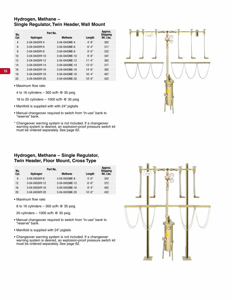
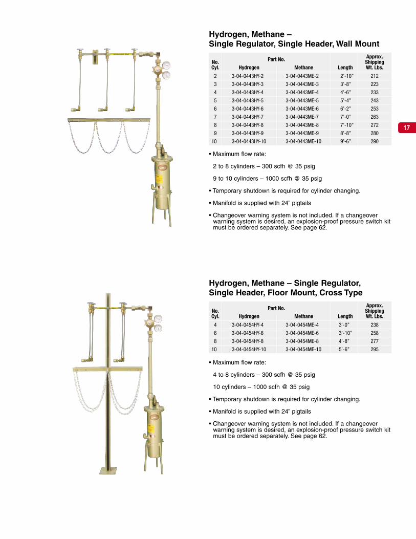
• Maximum flow rate:
2 to 8 cylinders – 300 scfh @ 35 psig
9 to 10 cylinders – 1000 scfh @ 35 psig
• Temporary shutdown is required for cylinder changing.
• Manifold is supplied with 24” pigtails
• Changeover warning system is not included. If a changeoverwarning system is desired, an explosion-proof pressure switch kitmust be ordered separately. See page 62.
Hydrogen, Methane –Single Regulator, Single Header, Wall Mount
Approx.No. Part No. ShippingCyl. Hydrogen Methane Length Wt. Lbs.
2 3-04-0443HY-2 3-04-0443ME-2 2’-10” 212
3 3-04-0443HY-3 3-04-0443ME-3 3’-8” 223
4 3-04-0443HY-4 3-04-0443ME-4 4’-6” 233
5 3-04-0443HY-5 3-04-0443ME-5 5’-4” 243
6 3-04-0443HY-6 3-04-0443ME-6 6’-2” 253
7 3-04-0443HY-7 3-04-0443ME-7 7’-0” 263
8 3-04-0443HY-8 3-04-0443ME-8 7’-10” 272
9 3-04-0443HY-9 3-04-0443ME-9 8’-8” 280
10 3-04-0443HY-10 3-04-0443ME-10 9’-6” 290
• Maximum flow rate:
4 to 8 cylinders – 300 scfh @ 35 psig
10 cylinders – 1000 scfh @ 35 psig
• Temporary shutdown is required for cylinder changing.
• Manifold is supplied with 24” pigtails
• Changeover warning system is not included. If a changeoverwarning system is desired, an explosion-proof pressure switch kitmust be ordered separately. See page 62.
Hydrogen, Methane – Single Regulator,Single Header, Floor Mount, Cross Type
Approx.No. Part No. ShippingCyl. Hydrogen Methane Length Wt. Lbs.
4 3-04-0454HY-4 3-04-0454ME-4 3’-0” 238
6 3-04-0454HY-6 3-04-0454ME-6 3’-10” 258
8 3-04-0454HY-8 3-04-0454ME-8 4’-8” 277
10 3-04-0454HY-10 3-04-0454ME-10 5’-6” 295
Rexarc manifold systems reduce cylinder handling costsand provide maximum safety.
Rexarc manifold systems let you concentrate your cylinders inone location so they’re not scattered throughout work areas.This reduces cylinder handling costs by giving you greater control over your gas supply.
Since your cylinders are located in a central area, you alwaysknow where they are. Plant safety is improved, record keepingis kept to a minimum and labor costs are cut because only afew minutes of one person’s time is necessary to service themanifold.
In addition, you increase production by eliminating interrup-tions at user stations to change cylinders and save gas as well,since all cylinders will be emptied uniformly.
Selecting the correct size oxygen, inert gas manifold.
1. Calculate the flow (scfh) at each use point in the piping sys-tem. Add the cubic feet per hour flow rate of each. The totalwill give you the volume of gas needed per hour.
2. The manifold should have enough cylinders to provide for atleast one week’s oxygen, inert gas requirements.
Oxygen, Inert GasDistributionSystems
18

19
Electronic Series Oxygen, Inert Gas –Floor Mount, Cross Type
Part NumberApprox.
No. 200 psig Delivery Pressure ShippingCyl. Oxygen Nitrogen Argon Length Wt. Lbs.
4 4-04-0156SG-4 4-04-0156SN-4 4-04-0156SA-4 3’-3” 130
8 4-04-0156SG-8 4-04-0156SN-8 4-04-0156SA-8 4’-7” 130
12 4-04-0156SG-12 4-04-0156SN-12 4-04-0156SA-12 6’-3” 140
16 4-04-0156SG-16 4-04-0156SN-16 4-04-0156SA-16 7’-11” 150
20 4-04-0156SG-20 4-04-0156SN-20 4-04-0156SA-20 9’-7” 160
Electronic Series Oxygen, Inert Gas –Wall Mount
Part NumberApprox.
No. 200 psig Delivery Pressure ShippingCyl. Oxygen Nitrogen Argon Length Wt. Lbs.
2 4-04-0156G-2 4-04-0156N-2 4-04-0156A-2 3’-3” 115
4 4-04-0156G-4 4-04-0156N-4 4-04-0156A-4 4’-7” 120
6 4-04-0156G-6 4-04-0156N-6 4-04-0156A-6 6’-3” 125
8 4-04-0156G-8 4-04-0156N-8 4-04-0156A-8 7’-11” 105
10 4-04-0156G-10 4-04-0156N-10 4-04-0156A-10 9’-7” 135
12 4-04-0156G-12 4-04-0156N-12 4-04-0156A-12 11’-3” 140
14 4-04-0156G-14 4-04-0156N-14 4-04-0156A-14 12’-11” 145
• Maximum flow rate: 6,000 scfh @ 200 psig
• Manifold switches automatically from “in-use” to “reserve” bank.
• Microprocessor control
• Servo actuator technology
• Automatic switching with status display
• Visual and audible changeover warning system is included
• Advanced remote monitoring capabilities – see page 60 fordetails.

20
• Maximum flow rate: 6,000 scfh @ 200 psig
• Manifold switches automatically from “in-use” to “reserve” bank.
• Microprocessor control
• Servo actuator technology
• Automatic switching with status display
• Visual and audible changeover warning system is included
• Advanced remote monitoring capabilities – see page 60 fordetails.
Electronic Series Oxygen, Inert Gas –Floor Mount, Cross Typefor Manifolded Cylinder Pallets
Electronic Series Oxygen, Inert Gas – WallMount for Manifolded Cylinder Pallets
Part NumberApprox.
No. 200 psig Delivery Pressure ShippingCyl. Oxygen Nitrogen Argon Length Wt. Lbs.
2 4-04-0168G-2 4-04-0168N-2 4-04-0168A-2 3’-3” 115
4 4-04-0168G-4 4-04-0168N-4 4-04-0168A-4 4’-7” 120
6 4-04-0168G-6 4-04-0168N-6 4-04-0168A-5 6’-3” 125
8 4-04-0168G-8 4-04-0168N-8 4-04-0168A-8 7’-11” 105
Part NumberApprox.
No. 200 psig Delivery Pressure ShippingCyl. Oxygen Nitrogen Argon Length Wt. Lbs.
2 4-04-0167G-2 4-04-0167N-2 4-04-0167A-2 3’-3” 120
4 4-04-0167G-4 4-04-0167N-4 4-04-0167A-4 4’-7” 130
6 4-04-0167G-6 4-04-0167N-6 4-04-0167A-5 6’-3” 140
8 4-04-0167G-8 4-04-0167N-8 4-04-0167A-8 7’-11” 150

21
*Specify gas by name• Maximum flow rate: 550 scfh
• Manifold switches automatically from “in-use” to “reserve” bank.
• Visual changeover warning system is included
• Remote changeover warning systems can be found on page 61
Oxygen, Inert Gas – Automatic Changeover,Floor Mount, Cross Type
Oxygen, Inert Gas –Automatic Changeover, Wall Mount
*Specify gas by name• Maximum flow rate: 550 scfh
• Manifold switches automatically from “in-use” to “reserve” bank.
• Visual changeover warning system is included
• Remote changeover warning systems can be found on page 61
Part No.Oxygen, Inert Gas* Approx.
No. 110 psig 200 psig ShippingCyl. Delivery Pressure Delivery Pressure Length Wt. Lbs.
2 4-04-0136-2 4-04-0136HP-2 3’-3” 90
4 4-04-0136-4 4-04-0136HP-4 4’-7” 95
6 4-04-0136-6 4-04-0136HP-6 6’-3” 100
8 4-04-0136-8 4-04-0136HP-8 7’-11” 105
10 4-04-0136-10 4-04-0136HP-10 9’-7” 110
12 4-04-0136-12 4-04-0136HP-12 11’-3” 115
14 4-04-0136-14 4-04-0136HP-14 12’-11” 120
16 4-04-0136-16 4-04-0136HP-16 14’-7” 125
18 4-04-0136-18 4-04-0136HP-18 16’-3” 130
20 4-04-0136-20 4-04-0136HP-20 17’-11” 135
Gas part No.Oxygen, Inert Gas* Approx.
No. 110 psig 200 psig ShippingCyl. Delivery Pressure Delivery Pressure Length Wt. Lbs.
4 4-04-0136S-4 4-04-0136SHP-4 3’-3” 120
8 4-04-0136S-8 4-04-0136SHP-8 4’-7” 130
12 4-04-0136S-12 4-04-0136SHP-12 6’-3” 140
16 4-04-0136S-16 4-04-0136SHP-16 7’-11” 150
20 4-04-0136S-20 4-04-0136SHP-20 9’-7” 160

22
Oxygen, Inert Gas – Automatic Changeover,Floor Mount, Cross Typefor Manifolded Cylinder Pallets
*Specify gas by name• Maximum flow rate: 550 scfh
• Manifold switches automatically from “in-use” to “reserve” bank.
• Visual changeover warning system is included
• Remote changeover warning systems can be found on page 61
Part No.Oxygen, Inert Gas* Approx.
No. 110 psig 200 psig ShippingCyl. Delivery Pressure Delivery Pressure Length Wt. Lbs.
2 4-04-0169SG-2 4-04-0169SHPG-2 3’-3” 120
4 4-04-0169SG-4 4-04-0169SHPG-4 4’-7” 130
6 4-04-0169SG-6 4-04-0169SHPG-6 6’-3” 140
8 4-04-0169SG-8 4-04-0169SHPG-8 7’-11” 150
Oxygen, Inert Gas –Automatic Changeover, Wall Mountfor Manifolded Cylinder Pallets
*Specify gas by name• Maximum flow rate: 550 scfh
• Manifold switches automatically from “in-use” to “reserve” bank.
• Visual changeover warning system is included
• Remote changeover warning systems can be found on page 61
Part No.Oxygen, Inert Gas* Approx.
No. 110 psig 200 psig ShippingCyl. Delivery Pressure Delivery Pressure Length Wt. Lbs.
2 4-04-0170G-2 4-04-0170HPG-2 3’-3” 115
4 4-04-0170G-4 4-04-0170HPG-4 4’-7” 120
6 4-04-0170G-6 4-04-0170HPG-6 6’-3” 125
8 4-04-0170G-8 4-04-0170HPG-8 7’-11” 105

23
The Laser –Automatic Changeover,Floor Mount, Cross Type
The Laser –Automatic Changeover, Wall Mount
*Specify gas by name• Maximum flow rate: 6,000 scfh
• Manifold switches automatically from “in-use” to “reserve” bank.
*Specify gas by name• Maximum flow rate: 6,000 scfh
• Manifold switches automatically from “in-use” to “reserve” bank.
Part No.Oxygen, Inert Gas*
No. 100 psig 200 psig 750 psigCyl. Delivery Pressure Delivery Pressure Delivery Pressure
2
4
6
8
Call Rexarc for Part Numbers and Pricing.
Part No.Oxygen, Inert Gas*
No. 100 psig 200 psig 750 psigCyl. Delivery Pressure Delivery Pressure Delivery Pressure
4
8
12
16
Call Rexarc for Part Numbers and Pricing.

24
Light Industrial Oxygen, Inert Gas –Wall Mount
Approx.No. Part No. Oxygen, Inert Gas* ShippingCyl. 0-40 psig 0-90 psig 0-130 psig Wt. Lbs.
4
6
8
*Specify gas by name• Maximum flow rate: 500 scfh
• Manifold switches automatically from “in-use” to “reserve” bank.
• Changeover warning system is not included. If a changeoverwarning system is desired, inquire.
Light Industrial Oxygen, Inert Gas –Floor Mount
Approx.No. Part No. Oxygen, Inert Gas* ShippingCyl. 0-40 psig 0-90 psig 0-130 psig Wt. Lbs.
2
4
*Specify gas by name• Maximum flow rate: 500 scfh
• Manifold switches automatically from “in-use” to “reserve” bank.
• Changeover warning system is not included. If a changeoverwarning system is desired, inquire.
Light Industrial Two Cylinder –Wall Mount
Approx.No. Part No. Oxygen, Inert Gas* ShippingCyl. 0-40 psig 0-90 psig 0-130 psig Wt. Lbs.
2
*Specify gas by name
• Manifold switches automatically from “in-use” to “reserve” bank.
• Changeover warning system is not included. If a changeoverwarning system is desired, inquire.
Call Rexarc for Part Numbers and Pricing.
Call Rexarc for Part Numbers and Pricing.
for Part Numbers and Pricing.

25
• Maximum flow rate: 500 scfh @ 100 psig delivery• Manifold switches automatically from “in-use” to “reserve” bank.• Visual and audible changeover warning system is activated when
reserve high pressure cylinders are in use• 350-500 psig liquid cylinder is required
• Maximum flow rate: 500 scfh @ 100 psig delivery• Manifold switches automatically from “in-use” to “reserve” bank.• Visual and audible changeover warning system is activated when
reserve high pressure cylinders are in use
Oxygen and Inert Gas – Floor Mount AutomaticChangeover, Dual Alarms Cryogenic LiquidPrimary/High Pressure Reserve
No. Approx.HP Part No. ShippingCyl. Oxygen Nitrogen Argon Length Wt. Lbs.
4 4-04-0151SG-4 4-04-0151SN-4 4-04-0151SA-4 3’-9” 74
6 4-04-0151SG-6 4-04-0151SN-6 4-04-0151SA-6 4’-8” 80
110 psig
No. Approx.HP Part No. ShippingCyl. Oxygen Nitrogen Argon Length Wt. Lbs.
4 4-04-0151SHPG-4 4-04-0151SHPN-4 4-04-0151SHPA-4 3’-9” 74
6 4-04-0151SHPG-6 4-04-0151SHPN-6 4-04-0151SHPA-6 4’-8” 80
200 psig
• Maximum flow rate: 500 scfh @ 100 psig delivery• Manifold switches automatically from “in-use” to “reserve” bank.• Visual and audible changeover warning system is activated when
reserve high pressure cylinders are in use
• Maximum flow rate: 500 scfh @ 100 psig delivery• Manifold switches automatically from “in-use” to “reserve” bank.• Visual and audible changeover warning system is activated when
reserve high pressure cylinders are in use• 350-500 psig liquid cylinder is required
Oxygen and Inert Gas – Wall Mount AutomaticChangeover, Dual Alarms Cryogenic LiquidPrimary/High Pressure Reserve
No. Approx.HP Part No. ShippingCyl. Oxygen Nitrogen Argon Length Wt. Lbs.
2 4-04-0151G-2 4-04-0151N-2 4-04-0151A-2 3’-0” 58
3 4-04-0151G-3 4-04-0151N-3 4-04-0151A-3 4’-5” 64
4 4-04-0151G-4 4-04-0151N-4 4-04-0151A-4 5’-4” 70
5 4-04-0151G-5 4-04-0151N-5 4-04-0151A-5 6’-3” 76
6 4-04-0151G-6 4-04-0151N-6 4-04-0151A-6 7’-1” 82
110 psig
No. Approx.HP Part No. ShippingCyl. Oxygen Nitrogen Argon Length Wt. Lbs.
2 4-04-0151HPG-2 4-04-0151HPN-2 4-04-0151HPA-2 3’-0” 58
3 4-04-0151HPG-3 4-04-0151HPN-3 4-04-0151HPA-3 4’-5” 64
4 4-04-0151HPG-4 4-04-0151HPN-4 4-04-0151HPA-4 5’-4” 70
5 4-04-0151HPG-5 4-04-0151HPN-5 4-04-0151HPA-5 6’-3” 76
6 4-04-0151HPG-6 4-04-0151HPN-6 4-04-0151HPA-6 7’-1” 82
200 psig

26
• Maximum flow rate: 500 scfh with two or more cylinders per side@ 100 psig
• Visual changeover warning system is included• Cryogenic vent kits are not included, see page 94.
• Maximum flow rate: 500 scfh with two or more cylinders per side@ 100 psig
• Manifold switches automatically from “in-use” to “reserve” bank.• Visual changeover warning system is included• Cryogenic vent kits are not included, see page 94.
Econ-O-Flow Oxygen, Inert Gas –Cryogenic Liquid Primary & Reserve,Automatic Changeover, Floor Mount
Econ-O-Flow Oxygen, Inert Gas –Cryogenic Liquid Primary & Reserve,Automatic Changeover, Wall Mount
Approx.No. Part No. ShippingCyl. Oxygen Nitrogen Argon Length Wt. Lbs.
2 4-04-0147G-2 4-04-0147N-2 4-04-0147A-2 3’-3” 100
4 4-04-0147G-4 4-04-0147N-4 4-04-0147A-4 4’-7” 105
6 4-04-0147G-6 4-04-0147N-6 4-04-0147A-6 6’-3” 110
Approx.No. Part No. ShippingCyl. Oxygen Nitrogen Argon Length Wt. Lbs.
2 4-04-0147SG-2 4-04-0147SN-2 4-04-0147SA-2 3’-3” 135
4 4-04-0147SG-4 4-04-0147SN-4 4-04-0147SA-4 4’-7” 145
6 4-04-0147SG-6 4-04-0147SN-6 4-04-0147SA-6 6’-3” 150
100 psig
• Maximum flow rate: 500 scfh with two or more cylinders per side@ 200 psig delivery
• Manifold switches automatically from “in-use” to “reserve” bank.• Visual changeover warning system is included• 350 psig delivery cylinder required• Cryogenic vent kits are not included, see page 94.
Approx.No. Part No. ShippingCyl. Oxygen Nitrogen Argon Length Wt. Lbs.
2 4-04-0147HPG-2 4-04-0147HPN-2 4-04-0147HPA-2 3’-3” 100
4 4-04-0147HPG-4 4-04-0147HPN-4 4-04-0147HPA-4 4’-7” 105
6 4-04-0147HPG-6 4-04-0147HPN-6 4-04-0147HPA-6 6’-3” 110
200 psig
100 psig
• Maximum flow rate: 500 scfh with two or more cylinders per side@ 200 psig delivery
• Manifold switches automatically from “in-use” to “reserve” bank.• Visual changeover warning system is included• 350 psig delivery cylinder required• Cryogenic vent kits are not included, see page 94.
Approx.No. Part No. ShippingCyl. Oxygen Nitrogen Argon Length Wt. Lbs.
2 4-04-0147SHPG-2 4-04-0147SHPN-2 4-04-0147SHPA-2 3’-3” 135
4 4-04-0147SHPG-4 4-04-0147SHPN-4 4-04-0147SHPA-4 4’-7” 145
6 4-04-0147SHPG-6 4-04-0147SHPN-6 4-04-0147SHPA-6 6’-3” 150
200 psig

27
• Maximum flow rate: 6500 scfh
• Manual changeover required to switch from “in-use” bank to“reserve” bank.
• Maximum delivery pressure: 200 psig
• Changeover warning system is not included. If a changeoverwarning system is desired, a pressure switch kit must be orderedseparately. See page 63.
Oxygen, Inert Gas – Single Regulator,Twin Header, Floor Mount, Cross Type
Approx.No. Part No. ShippingCyl. Oxygen Nitrogen Argon Length Wt. Lbs.
8 3-04-0431G-8 3-04-0431N-8 3-04-0431A-8 4’-10” 165
12 3-04-0431G-12 3-04-0431N-12 3-04-0431A-12 6’-6” 184
16 3-04-0431G-16 3-04-0431N-16 3-04-0431A-16 8’-2” 205
20 3-04-0431G-20 3-04-0431N-20 3-04-0431A-20 9’-10” 228
• Maximum flow rate: 6500 scfh
• Manual changeover required to switch from “in-use” bank to“reserve” bank.
• Maximum delivery pressure: 200 psig
• Changeover warning system is not included. If a changeoverwarning system is desired, a pressure switch kit must be orderedseparately. See page 63.
Oxygen, Inert Gas –Single Regulator, Twin Header, Wall Mount
Approx.No. Part No. ShippingCyl. Oxygen Nitrogen Argon Length Wt. Lbs.
4 3-04-0414G-4 3-04-0414N-4 3-04-0414A-4 3’-4” 156
6 3-04-0414G-6 3-04-0414N-6 3-04-0414A-6 5’-0” 172
8 3-04-0414G-8 3-04-0414N-8 3-04-0414A-8 6’-10” 191
10 3-04-0414G-10 3-04-0414N-10 3-04-0414A-10 8’-4” 208
12 3-04-0414G-12 3-04-0414N-12 3-04-0414A-12 10’-0” 261
14 3-04-0414G-14 3-04-0414N-14 3-04-0414A-14 11’-8” 276
16 3-04-0414G-16 3-04-0414N-16 3-04-0414A-16 13’-4” 291
18 3-04-0414G-18 3-04-0414N-18 3-04-0414A-18 15’-0” 306
20 3-04-0414G-20 3-04-0414N-20 3-04-0414A-20 16’-8” 322

28
• Maximum flow rate: 6500 scfh
• Temporary shutdown is required for cylinder changing.
• Maximum delivery pressure: 200 psig
• Changeover warning system is not included. If a changeoverwarning system is desired, a pressure switch kit must be orderedseparately. See page 63.
Oxygen, Inert Gas –Single Regulator, Single Header, Wall Mount
Approx.No. Part No. ShippingCyl. Oxygen Nitrogen Argon Length Wt. Lbs.
2 3-04-0417G-2 3-04-0417N-2 3-04-0417A-2 2’-1” 88
3 3-04-0417G-3 3-04-0417N-3 3-04-0417A-3 2’-11” 98
4 3-04-0417G-4 3-04-0417N-4 3-04-0417A-4 3’-9” 107
5 3-04-0417G-5 3-04-0417N-5 3-04-0417A-5 4’-7” 119
6 3-04-0417G-6 3-04-0417N-6 3-04-0417A-6 5’-5” 150
7 3-04-0417G-7 3-04-0417N-7 3-04-0417A-7 6’-3” 150
8 3-04-0417G-8 3-04-0417N-8 3-04-0417A-8 7’-1” 169
9 3-04-0417G-9 3-04-0417N-9 3-04-0417A-9 7’-11” 178
10 3-04-0417G-10 3-04-0417N-10 3-04-0417A-10 8’-9” 187
• Maximum flow rate: 6500 scfh
• Temporary shutdown is required for cylinder changing.
• Maximum delivery pressure: 200 psig
• Changeover warning system is not included. If a changeoverwarning system is desired, a pressure switch kit must be orderedseparately. See page 63.
Oxygen, Inert Gas – Single Regulator,Single Header, Floor Mount, Cross Type
Approx.No. Part No. ShippingCyl. Oxygen Nitrogen Argon Length Wt. Lbs.
4 3-04-0430G-4 3-04-0430N-4 3-04-0430A-4 2’-0” 92
6 3-04-0430G-6 3-04-0430N-6 3-04-0430A-6 2’-10” 104
8 3-04-0430G-8 3-04-0430N-8 3-04-0430A-8 3’-8” 118
10 3-04-0430G-10 3-04-0430N-10 3-04-0430A-10 4’-6” 129
29
Rexarc manifold systems reduce cylinder handling costsand provide maximum safety.
Rexarc manifold systems let you concentrate your cylinders inone location so they’re not scattered throughout work areas.This reduces cylinder handling costs by giving you greater control over your gas supply.
Since your cylinders are located in a central area, you alwaysknow where they are. Plant safety is improved, record keepingis kept to a minimum and labor costs are cut because only afew minutes of one person’s time is necessary to service themanifold.
In addition, you increase production by eliminating interrup-tions at user stations to change cylinders and save gas as well,since all cylinders will be emptied uniformly.
Selecting the correct size inert gas manifold.
1. Calculate the flow (scfh) at each use point in the piping sys-tem. Add the cubic feet per hour flow rate of each. The totalwill give you the volume of gas needed per hour.
2. The manifold should have enough cylinders to provide for atleast one week’s inert gas requirements.
4,500 psig InletInert GasDistribution Systems

30
• Maximum flow rate: 6,000 scfh @ 200 psig
• Manifold switches automatically from “in-use” to “reserve” bank.
• Microprocessor control
• Servo actuator technology
• Automatic switching with status display
• Visual and audible changeover warning system is included
• Advanced remote monitoring capabilities – see page 60 fordetails.
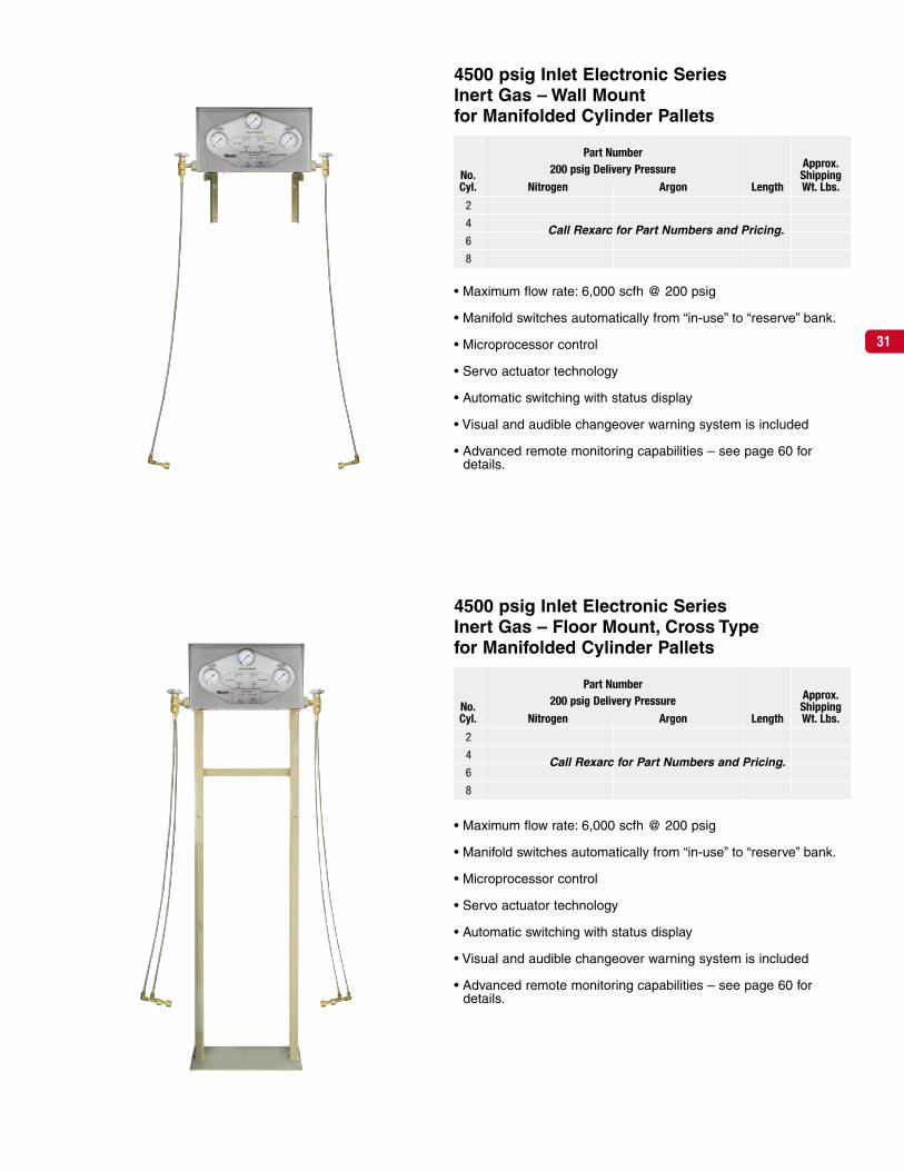
4500 psig Inlet Electronic SeriesInert Gas – Floor Mount, Cross Type
4500 psig Inlet Electronic SeriesInert Gas – Wall Mount
Part NumberApprox.
No. 200 psig Delivery Pressure ShippingCyl. Nitrogen Argon Length Wt. Lbs.
8 4-04-0160N-8 4-04-0160A-8 3’-3” 115
10 4-04-0160N-10 4-04-0160A-10 4’-7” 120
12 4-04-0160N-12 4-04-0160A-12 6’-3” 125
14 4-04-0160N-14 4-04-0160A-14 7’-11” 105
Part NumberApprox.
No. 200 psig Delivery Pressure ShippingCyl. Nitrogen Argon Length Wt. Lbs.
8 4-04-0161N-8 4-04-0161A-8 3’-3” 120
12 4-04-0161N-12 4-04-0161A-12 4’-7” 130
16 4-04-0161N-16 4-04-0161A-16 6’-3” 140
20 4-04-0161N-20 4-04-0161A-20 7’-11” 150
31
• Maximum flow rate: 6,000 scfh @ 200 psig
• Manifold switches automatically from “in-use” to “reserve” bank.
• Microprocessor control
• Servo actuator technology
• Automatic switching with status display
• Visual and audible changeover warning system is included
• Advanced remote monitoring capabilities – see page 60 fordetails.
4500 psig Inlet Electronic SeriesInert Gas – Floor Mount, Cross Typefor Manifolded Cylinder Pallets
4500 psig Inlet Electronic SeriesInert Gas – Wall Mountfor Manifolded Cylinder Pallets
Part NumberApprox.
No. 200 psig Delivery Pressure ShippingCyl. Nitrogen Argon Length Wt. Lbs.
2
4
6
8
Part NumberApprox.
No. 200 psig Delivery Pressure ShippingCyl. Nitrogen Argon Length Wt. Lbs.
2
4
6
8
Call Rexarc for Part Numbers and Pricing.
Call Rexarc for Part Numbers and Pricing.

32
• Maximum flow rate: 6500 scfh
• Manual changeover required to switch from “in-use” bank to“reserve” bank.
• Maximum pressure: 200 psig
• Maximum flow rate: 6500 scfh
• Manual changeover required to switch from “in-use” bank to“reserve” bank.
• Maximum pressure: 200 psig
4500 psig Inlet Inert Gas –Single Regulator, Twin Header,Floor Mount, Cross Type
Approx.No. Part No. ShippingCyl. Nitrogen Argon Length Wt. Lbs.
8 3-04-0618N-8 3-04-0618A-8 4’-10” 165
12 3-04-0618N-12 3-04-0618A-12 6’-6” 184
16 3-04-0618N-16 3-04-0618A-16 8’-2” 205
20 3-04-0618N-20 3-04-0618A-20 9’-10” 228
4500 psig Inlet Inert Gas –Single Regulator, Twin Header, Wall Mount
Approx.No. Part No. ShippingCyl. Nitrogen Argon Length Wt. Lbs.
4 3-04-0616N-4 3-04-0616A-4 3’-4” 156
6 3-04-0616N-6 3-04-0616A-6 5’-0” 172
8 3-04-0616N-8 3-04-0616A-8 6’-10” 191
10 3-04-0616N-10 3-04-0616A-10 8’-4” 208
12 3-04-0616N-12 3-04-0616A-12 10’-0” 261
14 3-04-0616N-14 3-04-0616A-14 11’-8” 276
16 3-04-0616N-16 3-04-0616A-16 13’-4” 291
18 3-04-0616N-18 3-04-0616A-18 15’-0” 306
20 3-04-0616N-20 3-04-0616A-20 16’-8” 322

33
• Maximum flow rate: 6500 scfh
• Temporary shutdown is required for cylinder changing.
• Maximum pressure: 200 psig
• Maximum flow rate: 6500 scfh
• Temporary shutdown is required for cylinder changing.
• Maximum pressure: 200 psig
4500 psig Inlet Inert Gas –Single Regulator, Single Header, Wall Mount
Approx.No. Part No. ShippingCyl. Nitrogen Argon Length Wt. Lbs.
2 3-04-0615N-2 3-04-0615A-2 2’-1” 88
3 3-04-0615N-3 3-04-0615A-3 2’-11” 98
4 3-04-0615N-4 3-04-0615A-4 3’-9” 107
5 3-04-0615N-5 3-04-0615A-5 4’-7” 119
6 3-04-0615N-6 3-04-0615A-6 5’-5” 150
7 3-04-0615N-7 3-04-0615A-7 6’-3” 150
8 3-04-0615N-8 3-04-0615A-8 7’-1” 169
9 3-04-0615N-9 3-04-0615A-9 7’-11” 178
10 3-04-0615N-10 3-04-0615A-10 8’-9” 187
4500 psig Inlet Inert Gas –Single Regulator, Single Header,Floor Mount, Cross Type
Approx.No. Part No. ShippingCyl. Nitrogen Argon Length Wt. Lbs.
4 3-04-0617N-4 3-04-0617A-4 2’-0” 92
6 3-04-0617N-6 3-04-0617A-6 2’-10” 104
8 3-04-0617N-8 3-04-0617A-8 3’-8” 118
10 3-04-0617N-10 3-04-0617A-10 4’-6” 129

34
Rexarc manifold systems reduce cylinder handling costsand provide maximum safety.
Rexarc manifold systems let you concentrate your cylinders inone location so they’re not scattered throughout work areas.This reduces cylinder handling costs by giving you greater control over your fuel gas supply.
Since your cylinders are located in a central area, you alwaysknow where they are. Plant safety is improved, record keepingis kept to a minimum and labor costs are cut because only afew minutes of one person’s time is necessary to service themanifold.
In addition, you increase production by eliminating interrup-tions at user stations to change cylinders and save gas as well,since all cylinders will be emptied uniformly.
No. of Cylinder Withdrawal Rate Total ContinuedCylinders Size in Pounds Std. Cu. Feet Useable Usage
Per Manifold Pounds Per Hour Per Hour Cu. Ft. of Gas Approx Hours
1 50 6-1/4 54 436 8
2 50 12-1/2 108 872 8
3 50 18-3/4 162 1,308 8
4 50 25 216 1,744 8
5 50 31-1/4 270 2,180 8
6 50 37-1/2 324 2,616 8
7 50 43-3/4 378 3,052 8
8 50 50 432 3,488 8
9 50 56-1/4 486 3,924 8
10 50 62-1/2 540 4,360 8
11 50 68-3/4 594 4,796 8
12 50 75 648 5,232 8
13 50 81-1/4 702 5,668 8
14 50 87-1/2 756 6,104 8
15 50 93-3/4 810 6,540 8
16 50 100 864 6,976 8
17 50 106-1/4 918 7,412 8
18 50 112-1/2 972 7,848 8
19 50 118-3/4 1,026 8,248 8
20 50 125 1,080 8,720 8
Carbon DioxideDistributionSystems
Selecting the correctcarbon dioxide manifold.
1. Calculate the flow (scfh) at each use pointin the piping system. Add the cubic feetper hour flow rate of each. The total willgive you the volume needed per hour.
2. The manifold should have enough cylin-ders to provide for at least one week’s car-bon dioxide gas requirements.
3. Heaters are recommended for withdrawrates above 35 scfh.
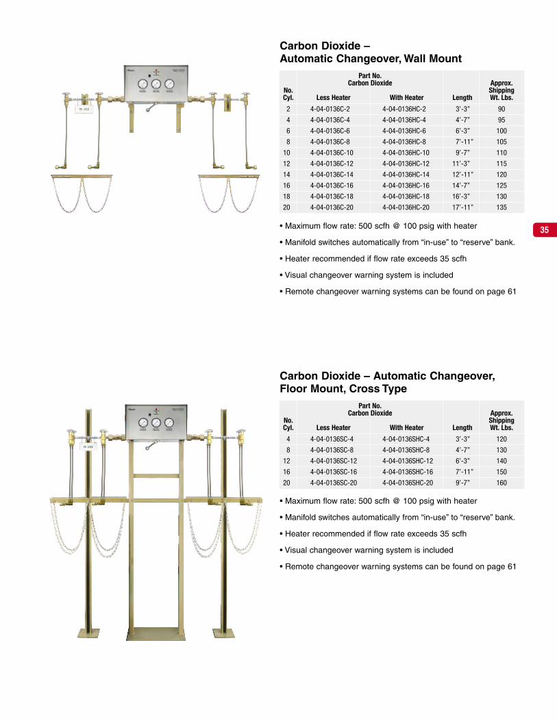
35• Maximum flow rate: 500 scfh @ 100 psig with heater
• Manifold switches automatically from “in-use” to “reserve” bank.
• Heater recommended if flow rate exceeds 35 scfh
• Visual changeover warning system is included
• Remote changeover warning systems can be found on page 61
Carbon Dioxide –Automatic Changeover, Wall Mount
• Maximum flow rate: 500 scfh @ 100 psig with heater
• Manifold switches automatically from “in-use” to “reserve” bank.
• Heater recommended if flow rate exceeds 35 scfh
• Visual changeover warning system is included
• Remote changeover warning systems can be found on page 61
Part No.Carbon Dioxide Approx.
No. ShippingCyl. Less Heater With Heater Length Wt. Lbs.
2 4-04-0136C-2 4-04-0136HC-2 3’-3” 90
4 4-04-0136C-4 4-04-0136HC-4 4’-7” 95
6 4-04-0136C-6 4-04-0136HC-6 6’-3” 100
8 4-04-0136C-8 4-04-0136HC-8 7’-11” 105
10 4-04-0136C-10 4-04-0136HC-10 9’-7” 110
12 4-04-0136C-12 4-04-0136HC-12 11’-3” 115
14 4-04-0136C-14 4-04-0136HC-14 12’-11” 120
16 4-04-0136C-16 4-04-0136HC-16 14’-7” 125
18 4-04-0136C-18 4-04-0136HC-18 16’-3” 130
20 4-04-0136C-20 4-04-0136HC-20 17’-11” 135
Carbon Dioxide – Automatic Changeover,Floor Mount, Cross Type
Part No.Carbon Dioxide Approx.
No. ShippingCyl. Less Heater With Heater Length Wt. Lbs.
4 4-04-0136SC-4 4-04-0136SHC-4 3’-3” 120
8 4-04-0136SC-8 4-04-0136SHC-8 4’-7” 130
12 4-04-0136SC-12 4-04-0136SHC-12 6’-3” 140
16 4-04-0136SC-16 4-04-0136SHC-16 7’-11” 150
20 4-04-0136SC-20 4-04-0136SHC-20 9’-7” 160

36
• Maximum flow rate: 500 scfh
• Manifold switches automatically from “in-use” to “reserve” bank.
• Maximum pressure: 200 psig
• Model -04-0093-8 with heaters is shown at right
• Heater specs: 480 watts, 115 volts, 4.37 amps
• Maximum flow rate: 500 scfh
• Manifold switches automatically from “in-use” to “reserve” bank.
• Maximum pressure: 200 psig
• Model 4-04-0094-4 with heaters is shown at right
• Heater specs: 480 watts, 115 volts, 4.37 amps
Carbon Dioxide – Twin Regulator, AutomaticChangeover, Floor Mount, Cross Type
Part No.Carbon Dioxide Approx.
No. ShippingCyl. Less Heaters With Heaters Length Wt. Lbs.
8 4-04-0088C-8 4-04-0093-8 5’-0” 235
12 4-04-0088C-12 4-04-0093-12 6’-8” 255
16 4-04-0088C-16 4-04-0093-16 8’-4” 275
20 4-04-0088C-20 4-04-0093-20 10’-0” 295
Carbon Dioxide – Twin Regulator,Automatic Changeover, Wall Mount
Part No.Carbon Dioxide Approx.
No. ShippingCyl. Less Heaters With Heaters Length Wt. Lbs.
4 4-04-0086C-4 4-04-0094-4 5’-1” 229
6 4-04-0086C-6 4-04-0094-6 6’-9” 249
8 4-04-0086C-8 4-04-0094-8 8’-5” 269
10 4-04-0086C-10 4-04-0094-10 10’-1” 289
12 4-04-0086C-12 4-04-0094-12 11’-9” 335
14 4-04-0086C-14 4-04-0094-14 13’-5” 350
16 4-04-0086C-16 4-04-0094-16 15’-1” 365
18 4-04-0086C-18 4-04-0094-18 16’-9” 380
20 4-04-0086C-20 4-04-0094-20 18’-5” 396

37
• Maximum flow rate: 500 scfh
• Manual changeover required to switch from “in-use” bank to“reserve” bank.
• Maximum pressure: 200 psig
• Model 3-04-0434-8 with heater is shown at left
• Heater specs: 480 watts, 115 volts, 4.37 amps
• Maximum flow rate: 500 scfh
• Manual changeover required to switch from “in-use” bank to“reserve” bank.
• Maximum pressure: 200 psig
• Model 3-04-0436-4 with heater is shown at left
• Heater specs: 480 watts, 115 volts, 4.37 amps
Carbon Dioxide – Single Regulator,Twin Header, Floor Mount, Cross Type
Part No.Carbon Dioxide Approx.
No. ShippingCyl. Less Heater With Heater Length Wt. Lbs.
8 3-04-0431C-8 3-04-0434-8 4’-10” 175
12 3-04-0431C-12 3-04-0434-12 6’-6” 195
16 3-04-0431C-16 3-04-0434-16 8’-2” 215
20 3-04-0431C-20 3-04-0434-20 9’-10” 235
Carbon Dioxide –Single Regulator, Twin Header, Wall Mount
Part No.Carbon Dioxide Approx.
No. ShippingCyl. Less Heater With Heater Length Wt. Lbs.
4 3-04-0414C-4 3-04-0436-4 3’-11” 166
6 3-04-0414C-6 3-04-0436-6 5’-7” 182
8 3-04-0414C-8 3-04-0436-8 7’-3” 201
10 3-04-0414C-10 3-04-0436-10 8’-11” 218
12 3-04-0414C-12 3-04-0436-12 10’-7” 271
14 3-04-0414C-14 3-04-0436-14 12’-3” 286
16 3-04-0414C-16 3-04-0436-16 13’-11” 301
18 3-04-0414C-18 3-04-0436-18 15’-7” 316
20 3-04-0414C-20 3-04-0436-20 17’-13” 332

38
• Maximum flow rate: 500 scfh
• Temporary shutdown is required for cylinder changing.
• Maximum pressure: 200 psig
• Model 3-04-0433-4 with heater is shown at right
• Heater specs: 480 watts, 115 volts, 4.37 amps
• Maximum flow rate: 500 scfh
• Temporary shutdown is required for cylinder changing.
• Maximum pressure: 200 psig
• Model 3-04-0435-4 with heater is shown at right
• Heater specs: 480 watts, 115 volts, 4.37 amps
Carbon Dioxide –Single Regulator, Single Header, Wall Mount
Part No.Carbon Dioxide Approx.
No. ShippingCyl. Less Heater With Heater Length Wt. Lbs.
2 3-04-0417C-2 3-04-0435-2 2’-1” 88
3 3-04-0417C-3 3-04-0435-3 2’-11” 98
4 3-04-0417C-4 3-04-0435-4 3’-9” 107
5 3-04-0417C-5 3-04-0435-5 4’-7” 119
6 3-04-0417C-6 3-04-0435-6 5’-5” 150
7 3-04-0417C-7 3-04-0435-7 6’-3” 159
8 3-04-0417C-8 3-04-0435-8 7’-1” 169
9 3-04-0417C-9 3-04-0435-9 7’-11” 178
10 3-04-0417C-10 3-04-0435-10 8’-9” 187
Carbon Dioxide – Single Regulator,Single Header, Floor Mount, Cross Type
Part No.Carbon Dioxide Approx.
No. ShippingCyl. Less Heater With Heater Length Wt. Lbs.
4 3-04-0430C-4 3-04-0433-4 2’-9” 100
6 3-04-0430C-6 3-04-0433-6 3’-7” 112
8 3-04-0430C-8 3-04-0433-8 4’-5” 126
10 3-04-0430C-10 3-04-0433-10 5’-3” 138

39
• Maximum flow rate: 150 scfh from a liquid cylinder @ 100 psig
• Manifold switches automatically from “in-use” to “reserve” bank.
• Internal heater supplied as standard
• Visual and audible changeover warning system is activated whenreserve high pressure cylinders are in use
• Maximum flow rate: 150 scfh from a liquid cylinder @ 100 psig
• Manifold switches automatically from “in-use” to “reserve” bank.
• Internal heater supplied as standard
• Visual and audible changeover warning system is activated whenreserve high pressure cylinders are in use
Carbon Dioxide –High Pressure Reserve,Automatic Changeover, Floor Mount
Carbon Dioxide –High Pressure Reserve,Automatic Changeover, Wall Mount
No. Approx.HP Part No. ShippingCyl. Carbon Dioxide Length Wt. Lbs.
2 4-04-0151C-2 3’-0” 58
3 4-04-0151C-3 4’-5” 64
4 4-04-0151C-4 5’-4” 70
5 4-04-0151C-5 6’-3” 76
6 4-04-0151C-6 7’-1” 82
No. Approx.HP Part No. ShippingCyl. Carbon Dioxide Length Wt. Lbs.
4 4-04-0151SC-4 3’-9” 74
6 4-04-0151SC-6 4’-8” 80

40
• Maximum flow rate: 150 scfh from a liquid cylinder @ 100 psig
• Manifold switches automatically from “in-use” to “reserve” bank.
• Heater recommended if flow rate exceeds 35 scfh
• Visual changeover warning system is included
• Maximum flow rate: 150 scfh from a liquid cylinder @ 100 psig
• Manifold switches automatically from “in-use” to “reserve” bank.
• Heater recommended if flow rate exceeds 35 scfh
• Visual changeover warning system is included
Carbon Dioxide –Low Pressure Reserve,Automatic Changeover, Wall Mount
Carbon Dioxide –Low Pressure Reserve,Automatic Changeover, Floor Mount
Part No.Carbon Dioxide Approx.
No. ShippingCyl. Less Heater With Heater Length Wt. Lbs.
2 4-04-0147C-2 4-04-0147HC-2 3’-3” 100
4 4-04-0147C-4 4-04-0147HC-4 4’-7” 105
6 4-04-0147C-6 4-04-0147HC-6 6’-3” 110
Part No.Carbon Dioxide Approx.
No. ShippingCyl. Less Heater With Heater Length Wt. Lbs.
2 4-04-0147SC-2 4-04-0147SHC-2 3’-3” 135
4 4-04-0147SC-4 4-04-0147SHC-4 4’-7” 145
6 4-04-0147SC-6 4-04-0147SHC-6 6’-3” 150

41
The Rexarc CO2 heater is ideal for applications where carbon dioxide is used at a rate higher than 35 standardcubic feet per hour.
The utilization of a heater allows for increased safety, betterefficiency, and longer life cycles for the regulators of this coldgas. This heater is capable of flows of 500 scfh at 200 psig.
The dual coil heating system allows for twice as much heatingsurface to ensure gas is adequately warmed as it travelsthrough the Rexarc CO2 heating unit. Save valuable downtime and gas by reducing the risk of regulator damage with thepurchase of the Rexarc CO2 Heating Unit.
Heater forCarbon Dioxide Gas,110 Volts
Heater for Carbon Dioxide Gas, 110 Volts
Approx.Shipping
Part No. Inlet Outlet Wt. Lbs.
2-04-1660 1” NPSM male 1” NPSM female 12

Rexarc manifold systems reduce cylinder handling costsand provide maximum safety.
Rexarc manifold systems let you concentrate your cylinders inone location so they’re not scattered throughout work areas.This reduces cylinder handling costs by giving you greater control over your fuel gas supply.
Since your cylinders are located in a central area, you alwaysknow where they are. Plant safety is improved, record keepingis kept to a minimum and labor costs are cut because only afew minutes of one person’s time is necessary to service themanifold.
In addition, you increase production by eliminating interrup-tions at user stations to change cylinders and save gas as well,since all cylinders will be emptied uniformly.
Description
Rexarc hydraulic flashback arresters are not required whenhydrogen, methane is used without oxygen or compressed air.
Convoluted stainless steel cylinder pigtails are used due to thespecific gravity of the gases.
Rexarc helium, hydrogen, methane distribution systems comply to National Fire Protection Association Bulletin #51.
Selecting the correct size helium, hydrogen,methane manifold.
To select the proper manifold for your operation, consider thesepoints:
1. Calculate the flow (scfh) at each use point in the piping sys-tem. Add the cubic feet per hour flow rate of each. The totalwill give you the volume of helium, hydrogen, methane need-ed per hour.
2. The manifold should have enough cylinders to provide for atleast one week’s gas requirements.
Helium, Hydrogen,Methane DistributionSystems withoutFlashback Arresters
42

43
• Maximum flow rate: 500 scfh @ 100 psig
• Manifold switches automatically from “in-use” to “reserve” bank.
• Manifold supplied with 24” convoluted pigtails
• Changeover warning system is not included. If a changeoverwarning system is desired, an explosion-proof pressure switch kitmust be ordered separately. See page 62.
Hydrogen, Methane – Automatic Changeover,Floor Mount, Cross Type
Hydrogen, Methane –Automatic Changeover, Wall Mount
Approx.No. Part No. ShippingCyl. Hydrogen Methane Length Wt. Lbs.
2 4-04-0136HY-2 4-04-0136ME-2 3’-3” 90
4 4-04-0136HY-4 4-04-0136ME-4 4’-7” 95
6 4-04-0136HY-6 4-04-0136ME-6 6’-3” 100
8 4-04-0136HY-8 4-04-0136ME-8 7’-11” 105
10 4-04-0136HY10 4-04-0136ME-10 9’-17” 110
12 4-04-0136HY-12 4-04-0136ME-12 11’-3” 115
14 4-04-0136HY-14 4-04-0136ME-14 12’-11” 120
16 4-04-0136HY-16 4-04-0136ME-16 14’-7” 125
18 4-04-0136HY-18 4-04-0136ME-18 16’-3” 130
20 4-04-0136HY-20 4-04-0136ME-20 17’-11” 135
Approx.No. Part No. ShippingCyl. Hydrogen Methane Length Wt. Lbs.
8 4-04-0136SHY-8 4-04-0136SME-8 4’-4” 130
12 4-04-0136SHY-12 4-04-0136SME-12 6’-3” 140
16 4-04-0136SHY-16 4-04-0136SME-16 7’-11” 150
20 4-04-0136SHY-20 4-04-0136SME-20 9’-7” 160

44
• Maximum flow rate: 500 scfh
• Manifold switches automatically from “in-use” to “reserve” bank.
• Manifold supplied with 24” convoluted pigtails
• Visual changeover warning system is included
• Remote changeover warning systems can be found on page 63
• Maximum flow rate: 500 scfh
• Manifold switches automatically from “in-use” to “reserve” bank.
• Manifold supplied with 24” convoluted pigtails
• Visual changeover warning system is included
• Remote changeover warning systems can be found on page 63
Helium – Automatic Changeover,Floor Mount, Cross Type
Helium GasPart No. Approx.
No. 100 psig 200 psig ShippingCyl. Delivery Pressure Delivery Pressure Length Wt. Lbs.
2 4-04-0136HE-2 4-04-0136HPHE-2 3’-3” 90
4 4-04-0136HE-4 4-04-0136HPHE-4 4’-7” 95
6 4-04-0136HE-6 4-04-0136HPHE-6 6’-3” 100
8 4-04-0136HE-8 4-04-0136HPHE-8 7’-11” 105
10 4-04-0136HE-10 4-04-0136HPHE-10 9’-7” 110
12 4-04-0136HE-12 4-04-0136HPHE-12 11’-3” 115
14 4-04-0136HE-14 4-04-0136HPHE-14 12’-11” 120
16 4-04-0136HE-16 4-04-0136HPHE-16 14’-7” 125
18 4-04-0136HE-18 4-04-0136HPHE-18 16’-3” 130
20 4-04-0136HE-20 4-04-0136HPHE-20 17’-11” 135
Helium GasPart No. Approx.
No. 100 psig 200 psig ShippingCyl. Delivery Pressure Delivery Pressure Length Wt. Lbs.
4 4-04-0136SHE-4 4-04-0136SHPHE-4 3’-3” 120
8 4-04-0136SHE-8 4-04-0136SHPHE-8 4’-7” 130
12 4-04-0136SHE-12 4-04-0136SHPHE-12 6’-3” 140
16 4-04-0136SHE-16 4-04-0136SHPHE-16 7’-11” 150
20 4-04-0136SHE-20 4-04-0136SHPHE-20 9’-7” 160
Helium –Automatic Changeover, Wall Mount
45
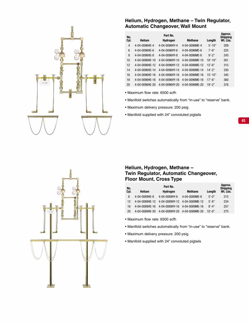
• Maximum flow rate: 6500 scfh
• Manifold switches automatically from “in-use” to “reserve” bank.
• Maximum delivery pressure: 200 psig
• Manifold supplied with 24” convoluted pigtails
• Maximum flow rate: 6500 scfh
• Manifold switches automatically from “in-use” to “reserve” bank.
• Maximum delivery pressure: 200 psig
• Manifold supplied with 24” convoluted pigtails
Helium, Hydrogen, Methane –Twin Regulator, Automatic Changeover,Floor Mount, Cross Type
Approx.No. Part No. ShippingCyl. Helium Hydrogen Methane Length Wt. Lbs.
8 4-04-0089HE-8 4-04-0089HY-8 4-04-0089ME-8 5’-0” 215
12 4-04-0089HE-12 4-04-0089HY-12 4-04-0089ME-12 5’-8” 234
16 4-04-0089HE-16 4-04-0089HY-16 4-04-0089ME-16 8’-4” 257
20 4-04-0089HE-20 4-04-0089HY-20 4-04-0089ME-20 10’-0” 275
Helium, Hydrogen, Methane – Twin Regulator,Automatic Changeover, Wall Mount
Approx.No. Part No. ShippingCyl. Helium Hydrogen Methane Length Wt. Lbs.
4 4-04-0096HE-4 4-04-0096HY-4 4-04-0096ME-4 5’-10” 209
6 4-04-0096HE-6 4-04-0096HY-6 4-04-0096ME-6 7’-6” 225
8 4-04-0096HE-8 4-04-0096HY-8 4-04-0096ME-8 9’-2” 243
10 4-04-0096HE-10 4-04-0096HY-10 4-04-0096ME-10 10’-10” 261
12 4-04-0096HE-12 4-04-0096HY-12 4-04-0096ME-12 12’-6” 315
14 4-04-0096HE-14 4-04-0096HY-14 4-04-0096ME-14 14’-2” 330
16 4-04-0096HE-16 4-04-0096HY-16 4-04-0096ME-16 15’-10” 345
18 4-04-0096HE-18 4-04-0096HY-18 4-04-0096ME-18 17’-6” 360
20 4-04-0096HE-20 4-04-0096HY-20 4-04-0096ME-20 19’-2” 376

46
• Maximum flow rate: 6500 scfh
• Manual changeover required to switch from “in-use” bank to“reserve” bank.
• Maximum delivery pressure: 200 psig
• Manifold supplied with 24” convoluted pigtails
• Maximum flow rate: 6500 scfh
• Manual changeover required to switch from “in-use” bank to“reserve” bank.
• Maximum delivery pressure: 200 psig
• Manifold supplied with 24” convoluted pigtails
Helium, Hydrogen, Methane –Single Regulator, Twin Header, Wall Mount
Approx.No. Part No. ShippingCyl. Helium Hydrogen Methane Length Wt. Lbs.
4 3-04-0444HE-4 3-04-0444HY-4 3-04-0444ME-4 4’-8” 156
6 3-04-0444HE-6 3-04-0444HY-6 3-04-0444ME-6 6’-4” 172
8 3-04-0444HE-8 3-04-0444HY-8 3-04-0444ME-8 8’-0” 191
10 3-04-0444HE-10 3-04-0444HY-10 3-04-0444ME-10 9’-8” 208
12 3-04-0444HE-12 3-04-0444HY-12 3-04-0444ME-12 11’-4” 261
14 3-04-0444HE-14 3-04-0444HY-14 3-04-0444ME-14 13’-0” 276
16 3-04-0444HE-16 3-04-0444HY-16 3-04-0444ME-16 14’-8” 291
18 3-04-0444HE-18 3-04-0444HY-18 3-04-0444ME-18 16’-4” 306
20 3-04-0444HE-20 3-04-0444HY-20 3-04-0444ME-20 18’-0” 322
Helium, Hydrogen, Methane – Single Reg-ulator, Twin Header, Floor Mount, Cross Type
Approx.No. Part No. ShippingCyl. Helium Hydrogen Methane Length Wt. Lbs.
8 3-04-0453HE-8 3-04-0453HY-8 3-04-0453ME-8 5’-0” 165
12 3-04-0453HE-12 3-04-0453HY-12 3-04-0453ME-12 6’-8” 184
16 3-04-0453HE-16 3-04-0453HY-16 3-04-0453ME-16 8’-4” 205
20 3-04-0453HE-20 3-04-0453HY-20 3-04-0453ME-20 10’-0” 228

47
• Maximum flow rate: 6500 scfh
• Temporary shutdown is required for cylinder changing.
• Maximum delivery pressure: 200 psig
• Manifold supplied with 24” convoluted pigtails
• Maximum flow rate: 6500 scfh
• Temporary shutdown is required for cylinder changing.
• Maximum delivery pressure: 200 psig
• Manifold supplied with 24” convoluted pigtails
Helium, Hydrogen, Methane –Single Regulator, Single Header, Wall Mount
Approx.No. Part No. ShippingCyl. Helium Hydrogen Methane Length Wt. Lbs.
2 3-04-0445HE-2 3-04-0445HY-2 3-04-0445ME-2 2’-10” 90
3 3-04-0445HE-3 3-04-0445HY-3 3-04-0445ME-3 3’-8” 100
4 3-04-0445HE-4 3-04-0445HY-4 3-04-0445ME-4 4’-6” 110
5 3-04-0445HE-5 3-04-0445HY-5 3-04-0445ME-5 5’-4” 120
6 3-04-0445HE-6 3-04-0445HY-6 3-04-0445ME-6 6’-2” 150
7 3-04-0445HE-7 3-04-0445HY-7 3-04-0445ME-7 7’-0” 160
8 3-04-0445HE-8 3-04-0445HY-8 3-04-0445ME-8 7’-10” 170
9 3-04-0445HE-9 3-04-0445HY-9 3-04-0445ME-9 8’-8” 180
10 3-04-0445HE-10 3-04-0445HY-10 3-04-0445ME-10 9’-6” 190
Helium, Hydrogen, Methane – Single Reg-ulator, Single Header, Floor Mount, Cross Type
Approx.No. Part No. ShippingCyl. Helium Hydrogen Methane Length Wt. Lbs.
4 3-04-0452HE-4 3-04-0452HY-4 3-04-0452ME-4 3’-0” 92
6 3-04-0452HE-6 3-04-0452HY-6 3-04-0452ME-6 3’-10” 104
8 3-04-0452HE-8 3-04-0452HY-8 3-04-0452ME-8 4’-8” 118
10 3-04-0452HE-10 3-04-0452HY-10 3-04-0452ME-10 5’-6” 129

General
Rexarc two cylinder manifolds are designed for a wide varietyof applications such as weld shops, restaurants and schools.
Rexarc two cylinder manifolds comply with standards recommended by the National Fire Protection AssociationBulletin #51.
Two CylinderDischargingManifolds
48

49
• Maximum pressure: 200 psig
• Manual changeover required to switch from “in-use” bank to“reserve” bank.
• Fuel gases must use a flashback arrester if used with an oxidizer.
Two Cylinder –Single Regulator, Wall Mount
Two Cylinder –Fuel Gas, Single Regulator, Wall Mount
Approx.No. Part No. ShippingCyl. Acetylene* LPG Type Gas** Length Height Wt. Lbs.
2 2-04-1535R-CGA 2-04-1535Y-CGA 32” 5’-4” 212
Approx.No. Part No. ShippingCyl. Helium Hydrogen Methane Wt. Lbs.
2 2-04-1583HE 2-04-1583HY 2-04-1583V 40
*Specify cylinder connections for acetylene (CGA 510 POL or CGA 300 Commercial)**Specify gas by name
• Maximum flow rate (SCFH) = cylinder capacity (Cu. Ft.) dividedby 10
• Manual changeover required to switch from “in-use” bank to“reserve” bank.
• Maximum pressure: 200 psig / 15 psig Acetylene

General
The Rexarc breathing air and oxygen manifolds are designedfor trans-filling to small breathing air cylinders or breathingapparatus such as firemen’s air packs.
Breathing Air,Oxygen Manifolds(Cascade Type)
50

51
• Filling Container is included
• Filling Container is included
Breathing Air, Oxygen Manifolds –3000 psig Inlet, (Cascade Type), Wall Mount
Breathing Air, Oxygen Manifolds –4500 psig Inlet, (Cascade Type), Wall Mount
Approx.No. Part No. ShippingCyl. Breathing Air Oxygen Length Wt. Lbs.
2 2-04-0319-2 2-04-0319G-2 2’-2” 173
3 2-04-0319-3 2-04-0319G-3 3’-2” 177
4 2-04-0319-4 2-04-0319G-4 4’-2” 181
5 2-04-0319-5 2-04-0319G-5 5’-2” 185
6 2-04-0319-6 2-04-0319G-6 6’-2” 189
7 2-04-0319-7 2-04-0319G-7 7’-2” 193
8 2-04-0319-8 2-04-0319G-8 8’-2” 197
9 2-04-0319-9 2-04-0319G-9 9’-2” 201
10 2-04-0319-10 2-04-0319G-10 10’-2” 205
Approx.No. Part No. ShippingCyl. Breathing Air Oxygen Length Wt. Lbs.
2 2-04-0319HP-2 2-04-0319GHP-2 2’-2” 175
3 2-04-0319HP-3 2-04-0319GHP-3 3’-2” 179
4 2-04-0319HP-4 2-04-0319GHP-4 4’-2” 183
5 2-04-0319HP-5 2-04-0319GHP-5 5’-2” 187
6 2-04-0319HP-6 2-04-0319GHP-6 6’-2” 191
7 2-04-0319HP-7 2-04-0319GHP-7 7’-2” 195
8 2-04-0319HP-8 2-04-0319GHP-8 8’-2” 199
9 2-04-0319HP-9 2-04-0319GHP-9 9’-2” 203
10 2-04-0319HP-10 2-04-0319GHP-10 10’-2” 207

PalletMaster 639Palletized CylinderDistribution System
52
General
One Rexarc PalletMaster does the work of two cradles, andprovides an immediate return on investment. PalletMaster canbe moved from pallet to pallet without tools, and is designed toreduce labor and cylinder handling costs. Use PalletMaster toconnect to 4, 8, 12, or 16 cylinders. Works with oxygen, inert,and fuel gases such as acetylene.
PalletMaster 639 is fully adjustable to fityour pallets. Shown here with 12 cylinders
PalletMaster 639S models include a shieldto protect the manifold and cylinders.
PalletMasterPalletized Cylinder Distribution System
Approx.No ShippingCyl. Description Part No. Wt. Lbs.
4PalletMaster, 4 cylinders 3-04-0639-4-CGA 51
PalletMaster with shield, 4 cylinders 3-04-0639S-4-CGA 72
8PalletMaster, 8 cylinders 3-04-0639-8-CGA 51
PalletMaster with shield, 8 cylinders 3-04-0639S-8-CGA 72
12PalletMaster, 12 cylinders 3-04-0639-12-CGA 51
PalletMaster with shield, 12 cylinders 3-04-0639S-12-CGA 72
16PalletMaster, 16 cylinders 3-04-0639-16-CGA 51
PalletMaster with shield, 16 cylinders 3-04-0639S-16-CGA 72

General
Rexarc portable distribution systems are intended for outdoor use and designed to supply gas to a single operator.Do not connect to permanent or temporary systems.
Components and material used are approved for the gases forwhich they were designed.
Rexarc portable distribution systems comply with National FireProtection Association Bulletin #51.
53
• Specify delivery pressure for all portable manifolds
Portable Manifolds –Oxygen and Inert Gas, Flexible Pigtails
Portable Manifolds –Fuel Gas, Flexible Pigtails
*Specify gas by name
• Specify delivery pressure for all portable manifolds
Approx.No. Part No. ShippingCyl. Acetylene LPG Type Gas* Length Wt. Lbs.
2 2-04-0723R-2 2-04-0738Y-2 17” 20
3 2-04-0723R-3 2-04-0738Y-3 31” 25
4 2-04-0723R-4 2-04-0738Y-4 45” 30
Approx.No. Part No. ShippingCyl. Argon Nitrogen Oxygen Length Wt. Lbs.
2 2-04-1196A-2 2-04-1196N-2 2-04-1196G-2 17” 20
3 2-04-1196A-3 2-04-1196N-3 2-04-1196G-3 31” 25
4 2-04-1196A-4 2-04-1196N-4 2-04-1196G-4 45” 30
PortableDistributionSystems

Description
Rexarc station outlets comply with National Fire ProtectionAssociation Bulletin #51, and are designed to supply efficientgas volume with minimum pressure reduction.
Each station outlet is in compliance with ANSI standard,marked with a positive identification label naming the gas beingused as well as being color coded. Each outlet is a preassem-bled unit ready for installation.
Installation
Before installing station outlets, piping should be cleaned,dried and tested in accordance with National Fire ProtectionBooklet #51. Station outlets should be installed at a height andlocation that affords protection as well as easy operator accessto the station supply valve. Apply appropriate pipe sealant onthe male threads only. Test system for leaks. If leaks are found,relieve pressure, repair and retest. Purge system before use.
StationOutlets
54

55
Single Station Outlets – with Regulator for Inert, Oxygen, Fuel Gas,and Flowmeter for Inert Gas
Regulator Approx.or Flowmeter Shipping
Gas Part No. Connection Length Wt. Lbs.
Inert w/Flowmeter* 2-04-1604 5/8”-18RH 19” 10
Inert w/Regulator* 2-04-1600 9/16”-18RH 19” 10
Oxygen w/Regulator 2-04-1608G 9/16”-18RH 22” 12
Acetylene w/Regulator 2-04-1608R 9/16”-18LH 22” 12
LPG Type w/Regulator* 2-04-1608Y 9/16”-18LH 22” 12
*Specify gas by name
• Specify delivery pressure for all station outlets with regulator
• Fits 3/4” or 1/2” piping systems (reducing bushing supplied)
• For service requiring station regulators.
Single Station Outlets – with “C” Size Regulator Connection for Inert, Oxygen, and Fuel Gas, and 5/8-18RHFlowmeter Connection for Inert Gas
Station Approx.Outlet Shipping
Gas Part No. Connection Length Wt. Lbs.
Inert Gas* 2-04-0406 5/8”-18RH 22” 7
Oxygen 2-04-0477G 7/8”-14RH 25” 8
Acetylene 2-04-0477R 7/8”-14LH 25” 8
LPG Type Gas* 2-04-0477Y 7/8”-14LH 25” 8
*Specify gas by name
• Fits 3/4” or 1/2” piping systems (reducing bushing supplied)
• For service requiring station regulators.

56
Double Station Outlets – with Regulators for Inert, Oxygen, Fuel Gas,and Flowmeters for Inert Gas
Regulator Approx.or Flowmeter Shipping
Gas Part No. Connections Length Wt. Lbs.
Inert w/Flowmeters* 2-04-1605 5/8”-18RH 22” 11
Inert w/Regulators* 2-04-1601 9/16”-18RH 22” 11
Oxygen w/Regulators 2-04-1609G 9/16”-18RH 25” 15
Acetylene w/Regulators 2-04-1609R 9/16”-18LH 25” 15
LPG Type w/Regulators* 2-04-1609Y 9/16”-18LH 25” 15
*Specify gas by name
• Specify delivery pressure for all station outlets with regulators
• Fits 3/4” or 1/2” piping systems (reducing bushing supplied)
• For service requiring station regulators.
Double Station Outlets – with “C” Size Regulator Connections for Inert, Oxygen and Fuel Gas, and 5/8-18RHFlowmeter Connections for Inert Gas
Station Approx.Outlet Shipping
Gas Part No. Connections Length Wt. Lbs.
Inert Gas* 2-04-0490 5/8”-18RH 22” 9
Inert Gas* 2-04-1712 7/8”-14RH (034) 22” 9
Oxygen 2-04-0522G 7/8”-14RH (024) 25” 9
Acetylene 2-04-0522R 7/8”-14LH (025) 25” 9
LPG Type Gas* 2-04-0522Y 7/8”-14LH (025) 25” 9
*Specify gas by name
• Fits 3/4” or 1/2” piping systems (reducing bushing supplied)
• For service requiring station regulators.

57
Double Station Outlets – with “B” Size Hose Connections for Air, Inert, Oxygen, Fuel Gas
Approx.Hose Shipping
Gas Part No. Inlet Connection Length Wt. Lbs.
Air 2-04-0597 3/4” NPT 5/8”-18RH 18-1/2” 4
Inert* 2-04-0490 3/4” NPT 5/8”-18RH 18-1/2” 4
Oxygen 2-04-0478G 3/4” NPT 9/16”-18RH 22” 5
Acetylene 2-04-0478R 3/4” NPT 9/16”-18LH 22” 5
LPG Type Gas* 2-04-0478Y 3/4” NPT 9/16”-18LH 22” 5
*Specify gas by name
• Fits 3/4” or 1/2” piping systems (reducing bushing supplied)
• For service not requiring station regulators.
*Specify gas by name
• Fits 3/4” or 1/2” piping systems (reducing bushing supplied)
• For service not requiring station regulators.
Single Station Outlets – with “B” Size Hose Connectionfor Air, Inert, Oxygen, Fuel Gas
Approx.Hose Shipping
Gas Part No. Inlet Connection Length Wt. Lbs.
Air 2-04-0588 3/4” NPT 5/8”-18LH 18-1/2” 4
Inert* 2-04-0406 3/4” NPT 5/8”-18RH 18-1/2” 4
Oxygen 2-04-0146G 3/4” NPT 9/16”-18RH 22” 5
Acetylene 2-04-0146R 3/4” NPT 9/16”-18LH 22” 5
LPG Type Gas* 2-04-0146Y 3/4” NPT 9/16”-18LH 22” 5

58
Multi-Torch Stationwith “B” Size Hose Connectionsfor Air, Inert, Oxygen, Fuel Gas
Multi-Gas Distribution Centerwith Regulators for Oxygen, Fuel Gas,Flowmeters for Inert Gas,and Quick-Disconnects for Air
Approx.Shipping
Part No. Height Length Depth Wt. Lbs.
3-04-0465 70” 55” 24” 290
Approx.Shipping
Gas Part No. Inlet Connection Length Wt. Lbs.
Inert* 2-04-1321 3/4” NPT 5/8”-18RH 49” 36
Oxygen 2-04-1319G 3/4” NPT 9/16”-18RH 46” 32
Acetylene 2-04-1319R 3/4” NPT 9/16”-18LH 46” 32
LPG Type Gas* 2-04-1319Y 3/4” NPT 9/16”-18LH 46” 32
Air 2-04-1320 2” NPT 3/4” NPT 43” 32
Individual Station Outlets
Approx.Shipping
Part No. Height Length Depth Wt. Lbs.
3-04-0413 49” 40” N/A 156
Approx.Shipping
Gas Part No. Inlet Connection Length Wt. Lbs.
Inert* 2-04-1321VA 3/4” NPT 5/8”-18RH 49” 36
Oxygen 2-04-1319VG-150 3/4” NPT 9/16”-18RH 46” 32
Acetylene 2-04-1319VR-15 3/4” NPT 9/16”-18LH 46” 32
LPG Type Gas* 2-04-1319VY-PSI 3/4” NPT 9/16”-18LH 46” 32
Air 2-04-1320V 2” NPT 3/4” NPT 43” 32
Complete Assembly
Individual Station Outlets
Approx.Shipping
Part No. Inlet Length Width Wt. Lbs.
3-04-0200 3/4” 31” 34” 157
Approx.Shipping
Gas Part No. Connection Length Wt. Lbs.
Air 3-04-0187 5/8”-18RH 28” 31
Inert* 3-04-0186A 5/8”-18RH 28” 31
Oxygen 3-04-0185G 9/16”-18RH 31” 30
Acetylene 3-04-0185R 9/16”-18LH 31” 30
LPG Type Gas* 3-04-0185Y 9/16”-18LH 31” 30
Complete Assembly
Individual Station Outlets
*Specify gas by name• Specify delivery pressure for all station outlets
*Specify gas by name• Specify delivery pressure for all station outlets
*Specify gas by name• Specify delivery pressure for all station outlets• For service not requiring station regulators.• Complies with ANSI A13.1, B32.2, B57.1, CSAB96-1965, NFPA
51 and CGA V-1.
Portable Multi-Gas Distribution Centerwith Regulators for Oxygen, Fuel Gas,Flowmeters for Inert Gas,and Quick-Disconnects for Air

59
Oxygen, Inert, CO2
General
Rexarc changeover warning systems let the operator know whenthe predetermined setting has been reached on gas supply.
When cylinder pressure falls below minimum pressure setting,the pressure switch activates a changeover warning system.Remote warning systems can be a warning bell, light, or both.
ChangeoverWarningSystems
Input Power110 or 24 V
ON/OFF switchSupplied by customer
Fuel Gas
Explosion-proofPressure Switch
Explosion-proofPressure Switchw/ Mounting Kit
Changeover Warning Systems
Light & Bell Bell
Plant styles Office styles
LightElectronic SeriesOxygen, Inert, CO2
Fuel Gas Oxygen, Inert, CO2
PressureSwitch
Transduceris built-in thecontrol box
Remote Statusand Audible/VisualChangeoverWarning System
Remote Statusand ChangeoverWarning Softwarefor your PC
Audible/visualdouble
gas
Audible/visualsinglegas
Visualdouble
gas
Visualsinglegas
PressureSwitch is built-in the
control box
Gas SupplyLine (pressure)

60
*Required for connection to the back of your PC.• Pressure Status
• Email notification
• Regulator status
Electronic Series Remote Status andAudible/Visual Changeover Warning System
Approx.Shipping
Description Part No. Wt. Lbs.
Electronic Series Remote 2-04-1678 5
Electronic Series Remote Statusand Changeover Warning Software for your PC
Approx.Shipping
Description Part No. Wt. Lbs.
Electronic Series PC Monitoring Software 1-39-0433 1
RS-485 to RS-232 Adapter* 1-04-2317 1
• Visual and audible changeover warning
• Pressure status

61
Remote Changeover Warning Box, Single Gas
Remote Changeover Warning Box, Double Gas
Audible Remote Changeover Warning Box,Single Gas
Approx.Shipping
Description Part No. Wt. Lbs.
Audible Remote Warning, Single Gas* – 24 volts 2-04-1495-24 5Audible Remote Warning, Single Gas* – 110 volts 2-04-1495-110 5
Approx.Shipping
Description Part No. Wt. Lbs.
Remote Warning, Double Gas* – 24 volts 2-04-1522-24 3Remote Warning, Double Gas* – 110 volts 2-04-1522-110 3
Approx.Shipping
Description Part No. Wt. Lbs.
Remote Warning, Single Gas* – 24 volts 2-04-1521-24 2Remote Warning, Single Gas* – 110 volts 2-04-1521-110 2
*Specify gas by name
*Specify gas by name
*Specify gas by name
Audible Remote Changeover Warning Box,Double Gas
Approx.Shipping
Description Part No. Wt. Lbs.
Audible Remote Warning, Double Gas* – 24 volts 2-04-1710-24 –Audible Remote Warning, Double Gas* – 110 volts 2-04-1710-110 –

62
Changeover Warning Systems –Light & Bell for Fuel Gas
Approx.Shipping
Description Part No. Wt. Lbs.
Warning System w/Light & Bell, 4-15 psig 2-04-0567 32Warning System w/Light & Bell, 15-40 psig 2-04-0599 32Warning System w/Light & Bell, 5-140 psig 2-04-1059 32Warning System w/Light & Bell, 10-350 psig 2-04-0879 32
Changeover Warning Systems –Light for Fuel Gas
Approx.Shipping
Description Part No. Wt. Lbs.
Warning System w/Light, 4-15 psig 2-04-0371 28Warning System w/Light, 15-40 psig 2-04-0495 28Warning System w/Light, 5-140 psig 2-04-1058 28Warning System w/Light, 10-350 psig 2-04-1292 28
Changeover Warning Systems –Bell for Fuel Gas
Approx.Shipping
Description Part No. Wt. Lbs.
Warning System w/Bell, 4-15 psig 2-04-0370 28Warning System w/Bell, 15-40 psig 2-04-0494 28Warning System w/Bell, 5-140 psig 2-04-1057 28Warning System w/Bell, 10-350 psig 2-04-1291 28

63
Changeover Warning Systems –Light for Oxygen and Inert Gas
Changeover Warning Systems –Bell for Oxygen and Inert Gas
Changeover Warning Systems –Light & Bell for Oxygen and Inert Gas
Approx.Shipping
Description Part No. Wt. Lbs.
Warning System w/Light & Bell, 30-300 psig 2-04-0561 32
Warning Box w/Light & Bell 2-04-0780 17
Approx.Shipping
Description Part No. Wt. Lbs.
Warning System w/Light, 30-300 psig 2-04-0374 28
Warning Box w/Light 2-04-0883 17
Approx.Shipping
Description Part No. Wt. Lbs.
Warning System w/Bell, 30-300 psig 2-04-0373 28
Warning Box w/Bell 2-04-0882 17

64
Explosion-Proof Pressure Switchfor Fuel Gas
Approx.Shipping
Description Part No. Wt. Lbs.
Explosion-proof Pressure Switch, 4-15 psig 1-04-0255 12Explosion-proof Pressure Switch, 15-40 psig 1-04-0445 12Explosion-proof Pressure Switch, 5-140 psig 1-04-1037 12Explosion-proof Pressure Switch, 10-350 psig 1-06-0297 12
Explosion-Proof Pressure Switchwith Mounting Kit – for Fuel GasManifolds with Control Boxes
Approx.Shipping
Description Part No. Wt. Lbs.
Explosion-proof Kit, 4-15 psig 2-04-1593-17 12Explosion-proof Kit, 15-40 psig 2-04-1593-55 12Explosion-proof Kit, 5-140 psig 2-04-1593-130 12
Pressure Switch for Oxygen and Inert Gas
Approx.Shipping
Description Part No. Wt. Lbs.
Pressure Switch, 30-100 psig 1-04-1814-100 12
Pressure Switch, 30-300 psig 1-04-1814-300 12
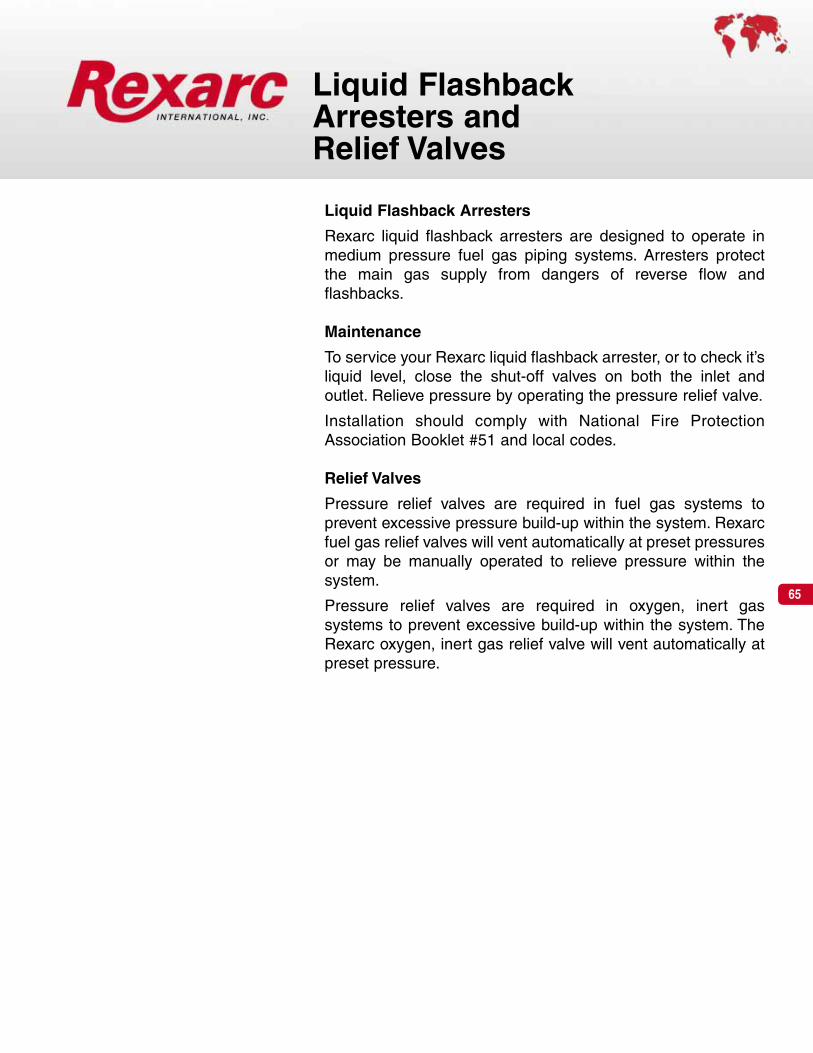
65
Liquid Flashback Arresters
Rexarc liquid flashback arresters are designed to operate inmedium pressure fuel gas piping systems. Arresters protectthe main gas supply from dangers of reverse flow and flashbacks.
Maintenance
To service your Rexarc liquid flashback arrester, or to check it’sliquid level, close the shut-off valves on both the inlet and outlet. Relieve pressure by operating the pressure relief valve.
Installation should comply with National Fire ProtectionAssociation Booklet #51 and local codes.
Relief Valves
Pressure relief valves are required in fuel gas systems to prevent excessive pressure build-up within the system. Rexarcfuel gas relief valves will vent automatically at preset pressuresor may be manually operated to relieve pressure within the system.
Pressure relief valves are required in oxygen, inert gas systems to prevent excessive build-up within the system. TheRexarc oxygen, inert gas relief valve will vent automatically atpreset pressure.
Liquid FlashbackArresters andRelief Valves

66
Liquid Flashback Arresters – 100 scfh
Liquid Flashback Arresters – 300 scfh
Liquid Flashback Arresters – 1000 scfh
• Floor stand and flashback fluid are included
• Flashback fluid is included
• Floor stand and flashback fluid are included
Inlet Vent Approx.and Pressure Shipping
Gas Part No. Outlet psig Wt. Lbs.
Acetylene 3-01-0118 3/4” NPT 20 39
LPG Type Gas 3-01-0118S 3/4” NPT 40 39
Hydrogen 3-01-0118S 3/4” NPT 40 39
Natural Gas 3-01-0118SF 3/4” NPT 10 39
Natural Gas 3-01-0118SL 3/4” NPT 2 39
Inlet Vent Approx.and Pressure Shipping
Gas Part No. Outlet psig Wt. Lbs.
Acetylene 3-01-0109 1” NPT 20 55
LPG Type Gas 3-01-0109S 1” NPT 40 55
Hydrogen 3-01-0109S 1” NPT 40 55
Natural Gas 3-01-0071SF 1” NPT 10 55
Natural Gas 3-01-0071SL 1” NPT 2 55
Inlet Vent Approx.and Pressure Shipping
Gas Part No. Outlet psig Wt. Lbs.
Acetylene 3-01-0110 1-1/2” NPT 20 123
LPG Type Gas 3-01-0110S 1-1/2” NPT 40 123
Hydrogen 3-01-0110S 1-1/2” NPT 40 123
Natural Gas 3-01-0070SF 1-1/2” NPT 10 123
Natural Gas 3-01-0070SL 1-1/2” NPT 2 123

67
Liquid Flashback Arrester – 200 psig/1000 scfh
Liquid Flashback Arresters – 2500 scfh
• Floor stand and flashback fluid are included
• Floor stand and flashback fluid are included
Inlet Vent Approx.and Pressure Shipping
Gas Part No. Outlet psig Wt. Lbs.
Acetylene 3-01-0111 2” NPT 20 463
LPG Type Gas 3-01-0111S 2” NPT 40 463
Hydrogen 3-01-0111S 2” NPT 40 463
Natural Gas 3-01-0069SF 2” NPT 10 463
Natural Gas 3-01-0069SL 2” NPT 2 463
Inlet Vent Approx.and Pressure Shipping
Gas Part No. Outlet psig Wt. Lbs.
All Except 3-01-0110-1 1-1/2” NPT 200 145Acetylene

68
Liquid Flashback Arresters – 5000 scfh
• Floor stand and flashback fluid are included
Inlet Vent Approx.and Pressure Shipping
Gas Part No. Outlet psig Wt. Lbs.
Acetylene 3-01-0081 4” NPT 20 563
LPG Type Gas 3-01-0081S 4” NPT 40 563
Hydrogen 3-01-0081S 4” NPT 40 563
Natural Gas 3-01-0081SF 4” NPT 10 563
Natural Gas 3-01-0081SL 4” NPT 2 563
Liquid Flashback Arresters – 15000 scfh
• Floor stand and flashback fluid are included
Inlet Vent Approx.and Pressure Shipping
Gas Part No. Outlet psig Wt. Lbs.
Call Rexarc for Part Numbers and Pricing.

69
• Specify gas by name and operating pressure
Fuel Gas Relief Valve — Not Field Repairable
Oxygen, Inert Gas Relief Valve— Not Field Repairable
Fuel Gas Relief Valve — Not Field Repairable
Vent Approx.Pressure Shipping
Gas Part No. psig Inlet Outlet Wt. Lbs.
Acetylene 1-05-0160 20 3/4” 3/4” 2-1/2
LPG Type Gas 1-05-0160 20 3/4” 3/4” 2-1/2
LPG Type Gas 1-05-0161 40 3/4” 3/4” 2-1/2
Hydrogen 1-05-0161 40 3/4” 3/4” 2-1/2
Vent Approx.Pressure Shipping
Gas Part No. psig Inlet Outlet Wt. Lbs.
Natural Gas 3-05-0025SF 10 3/4” 1” 10-1/2
Natural Gas 3-05-0025SL 2 3/4” 1” 10-1/2
Operating Approx.Pressure Shipping
Part No. psig Inlet Outlet Wt. Lbs.
1-04-1915 0-600 1/2” 1/2” 1
Relief Valve for all Fuel Gases exceptAcetylene — Not Field Repairable
Vent Approx.Pressure Shipping
Part No. psig Inlet Outlet Wt. Lbs.
1-25-0813-2 200 1/2” 3/4” 2-1/2

For operator safety
• Use regulators only with the gas they are designed for. Anyother gas could result in an explosion.
• Never oil or grease a regulator, or any other apparatus usedwith a compressed gas.
• Never connect a regulator to a source of pressure greaterthan the regulator is designed for.
• Always follow Rexarc’s instructions when installing and shut-ting down the regulator.
CylinderRegulators,Single Stage
Torch
CylinderRegulators
Flow tests are conducted with Air at 70º F.To determine the flow rate for a specificgas, multiply test results by the correctionfactor in the table below.
Acetylene 1.05
Mapp Gas .82
Natural Gas 1.28
Oxygen .95
Propane .80
70

71
Single Stage Cylinder Regulators –
RWP1200 SeriesAcetylene 2-15 psigLPG type gas 2-45 psigOxygen 2-80 psig
The RWP1200 Series is designed to be usedwith the Rexarc Industrial 1000 and Industrial2000 Cutting and Welding Systems. Theseregulators can also be used for other applica-tions within the operating specifications.
Body and bonnet: Solid forged brass,machined
Diaphragm: Neoprene reinforced with Nylon
Seat: Neoprene, stem type
Relief valve: Spring loaded
Inlet filter: 50 microns
Max. inlet pressure: 3000 psig
20
550
500
450
400
350
300
250
200
150
100
50
04 6 8 10 12 15Delivery Pressure, psig
Flow
Rat
e,sc
fh
300 psig inlet
0
100
200
300
400
500
600
700
800
900
1000
1100
1200
1300
1400
1500
Delivery Pressure, psig
Flow
Rat
e,sc
fh
300 psig inlet
102
2400
2200
2000
1800
1600
1400
1200
1000
800
600
400
200
020 30 40 50 60 70 80Delivery Pressure, psig
Flow
Rat
e,sc
fh
2500 psig inlet
Tested with air at 70° Fahrenheit.
2 5 10 15 20 25 30 35 40 45
Operating Connections Approx.Range Shipping
Gas Part No. psig Inlet Outlet Wt. Lbs.
RWP001203 CGA 300Acetylene
RWP0012052-15
9/16”-18LH Ext.
LPG Type Fuel Gases RWP001206 2-45CGA 510 5-1/2
Oxygen RWP001201 2-80 CGA 540 9/16”-18RH Ext.
Ordering Information

72
Single Stage Cylinder Regulators –
RWP1200 SeriesAir, Argon, Carbon Dioxide, Helium,Hydrogen and Nitrogen 2-80 psig
The RWP1200 Series is designed to be usedwith GMAW, FCAW, GTAW, PAW, PACprocesses and other applications within theoperating specifications.
Body and bonnet: Solid forged brass,machined
Diaphragm: Neoprene reinforced with Nylon
Seat: Teflon, stem type
Relief valve: Spring loaded
Inlet filter: 50 microns
Max. inlet pressure: 3000 psig
102
2400
2200
2000
1800
1600
1400
1200
1000
800
600
400
200
020 30 40 50 60 70 80Delivery Pressure, psig
Flow
Rat
e,sc
fh
2500 psig inlet
Tested with air at 70° Fahrenheit.
Operating Connections Approx.Range Shipping
Gas Part No. psig Inlet Outlet Wt. Lbs.
RWP001211 CGA 346Air
RWP001212 CGA 5909/16”-18RH Ext.
Argon RWP001208 CGA 580
Carbon Dioxide RWP001210 2-80 CGA 320 9/16”-18RH Int. 5-1/2
Helium RWP001208 CGA 580
Hydrogen RWP001207 CGA 350 9/16”-18LH Ext.
Nitrogen RWP001208 CGA 580 9/16”-18RH Int.
Ordering Information

73
General
A station regulator is used in a gas manifold delivery system toreduce pipe line pressure to that which is required by an indi-vidual operator at a workstation.
Station regulators are listed by the maximum capacity rec-ommended for applications.
StationRegulators,Single Stage
Fuel Gas Manifold Oxygen Manifold
Workstation #2Workstation #1
GasEconomizer
Torch
Flow tests are conducted with Air at 70º F.To determine the flow rate for a specificgas, multiply test results by the correctionfactor in the table below.
Acetylene 1.05
Mapp Gas .82
Natural Gas 1.28
Oxygen .95
Propane .80
StationRegulators
GasEconomizer
Torch
StationRegulators

Single Stage Station Regulators –
6200 SeriesAcetylene 0-15 psigLPG, Hydrogen 0-40 psigOxygen, Argon, Carbon Dioxide, Helium,Nitrogen up to 150 psig
The 6200 Series is used in a gas manifolddelivery system to reduce pipe line pressure tothat which is required by an individual operatorat a workstation.
Body: Solid forged brass, machined
Diaphragm: Neoprene
Seat: Neoprene
Inlet filter: Screen
Max. inlet pressure: 200 psig
7425 50 75 100 125 1502
0
100
200
300
400
500
600
700
800
900
Delivery Pressure, psig
Flow
Rat
e,sc
fh
200 psig inlet
Tested with air at 70° Fahrenheit.
2000
20
40
60
80
100
120
140
160
180
200
220
240
260
4 6 8 10 12 15
Flow
Rat
e,sc
fh
15 psig inlet
Delivery Pressure, psig20
00
20
40
60
80
100
120
140
160
180
200
220
240
260
4 6 8 10 12 15
Flow
Rat
e,sc
fh
15 psig inlet
Delivery Pressure, psig
Operating Connections Approx.Range Shipping
Gas Part No. psig Inlet Outlet Wt. Lbs.
Acetylene 000006203 0-15
000006208 0-15 7/8”-14LH Int. 9/16”-18LH Ext.LPG Type Fuel Gases
000006207 0-40
000006211 0-15
000006204 0-40Oxygen
000006210 0-807/8”-14RH Int. 9/16”-18RH Ext.
000006200 0-150 6
000006208 15Hydrogen
000006207 407/8”-14LH Int. 9/16”-18LH Ext.
000006212 15
Argon, Carbon Dioxide 000006205 40
Helium or Nitrogen 000006209 807/8”-14RH Ext. 5/8”-18RH Ext
000006201 150
Ordering Information

75
General
A line regulator is used in a gas delivery system to reduce thepipe line pressure to the same for all workstations.
Line regulators are listed by the maximum capacity recom-mended for applications.
LineRegulators,Single Stage
OxygenLineRegulator
Fuel GasLine
Regulator
Workstation #2Workstation #1
GasEconomizer
Torch
GasEconomizer
Torch
Flow tests are conducted with Air at 70º F.To determine the flow rate for a specificgas, multiply test results by the correctionfactor in the table below.
Acetylene 1.05
Mapp Gas .82
Natural Gas 1.28
Oxygen .95
Propane .80

76
Single Stage Line Regulators –
RXA7200 SeriesAcetylene 0-15 psigLPG type gas 0-40 psigOxygen 0-150 psig
The RXA7200 Series is used in a gas deliverysystem to reduce pipe line pressure to the samefor all workstations.
Body: Solid forged brass, machined
Diaphragm: Neoprene
Seat: Neoprene
Max. inlet pressure: 350 psig
2000
20
40
60
80
100
120
140
160
180
200
220
240
260
4 6 8 10 12 15
Flow
Rat
e,sc
fh
15 psig inlet
2 5 10 15 20 25 30 35 40 450
50
100
150
200
250
300
350
400
450
500
550
Delivery Pressure, psigDelivery Pressure, psig
Flow
Rat
e,sc
fh
45 psig inlet
25 50 75 100 125 15020
100
200
300
400
500
600
700
800
900
Delivery Pressure, psig
Flow
Rat
e,sc
fh
200 psig inlet
Tested with air at 70° Fahrenheit.
Operating Connections Approx.Range Shipping
Gas Part No. psig Inlet Outlet Wt. Lbs.
Acetylene RXA007203 0-15
LPG Type Fuel Gases RXA007204 0-40
RXA007201 0-801/2” NPT Int. 1/2” NPT Int. 5-1/2
OxygenRXA007200 0-150
Ordering Information

77
CylinderRegulator-Flowmeters andRegulator-Flowgauges
Shielding and plasma gases are used in many welding pro-cedures – and different types of flow measuring devices arerequired to achieve the results desired. The most widely usedprocesses are:
• Gas Metal Arc Welding (GMAW)
• Flux Cored Arc Welding (FCAW)
• Gas Tungsten Arc Welding (GTAW)
• Plasma Arc Welding (PAW)
• Plasma Arc Cutting (PAC)
Gases and gas mixtures commonly used for these process-es are listed in the chart below.
This chapter also includes Hydrogen and Oxygen regulators.
Pure shielding gasesArgonCarbon DioxideHelium
Two component shielding gas mixturesArgon + 20-50% HeliumArgon + less than 1% OxygenArgon + 1-2% Carbon Dioxide
+ 3-5% Carbon Dioxide+ 20-30% Carbon Dioxide
Argon + 2-4% HeliumHelium + 25% ArgonCarbon Dioxide + up to 20% OxygenCarbon Dioxide + 3-10% Oxygen
Three component shielding gas mixturesArgon + 3-10% Oxygen + 15% Carbon DioxideHelium + 7.5 % Argon + 2.5% Carbon Dioxide
Plasma cutting gasesCompressed airNitrogen
Flow tests are conducted with Air at 70ºF. To determine the flow rate for a specificgas, multiply test results by the correctionfactor in the table below.
Argon .85
Carbon Dioxide .81
Helium 2.69
Hydrogen 3.79
Nitrogen 1.02
Oxygen .95

78
Single StageCylinder Regulator-Flowmeters –
RWP001208FM andRWP001210FMArgon 1-60 scfhHelium 1-180 scfhNitrogen 1-70 scfhCarbon Dioxide 1-60 scfh
The RWP001200FM Series regulator-flowme-ters are designed for easy adjustment andprecise measurement of gas flows.
Regulator: Solid forged brass, machined, fac-tory pre-set 50 psig
Flowmeter: Impact resistant pyrex® flow tubewith easy to read scfh scales for Argon,Helium, Nitrogen and Carbon Dioxide
Cylinder contents gauge: 0-3000 psig
Max. inlet pressure: 3000 psig
* Continuous flow of Carbon Dioxide in excess of 30 scfh may cause damage the regulator due to freezing.
Operating Connections Approx.Range Shipping
Gas Part No. scfh Inlet Outlet Wt. Lbs.
Argon 1-60
Helium RWP001208FM 1-180 CGA 580
Nitrogen 1-705/8”-18RH Int. 4
Carbon Dioxide RWP001210FM 1-60* CGA 320
Ordering Information

79
Single StageCylinder Regulator-Flowgauges –
RWP001200AH andRWP001200CArgon 1-60 scfhHelium 1-190 scfhCarbon Dioxide 1-60 scfh
These regulator-flowgauges are analternative to flowmeters. They use ametered orifice at the outlet. Gas flow iscontrolled by adjusting the gas pressureagainst the orifice. The resulting flowrate is accurate and can be easily readon the scfh gauge.
Regulator: Solid forged brass,machined
Flowgauge: Easy to read scfh scalesfor Argon and Helium or CarbonDioxide
Cylinder pressure gauge: 0-4000 psig
Max. inlet pressure: 3000 psig
* Continuous flow of Carbon Dioxide in excess of 30 scfh may cause damage the regulator due to freezing.
Operating Connections Approx.Range Shipping
Gas Part No. scfh Inlet Outlet Wt. Lbs.
Argon 1-60
HeliumRWP001200AH
1-190CGA 580
5/8”-18RH Int. 3-1/2
Carbon Dioxide RWP001200C 1-60* CGA 320
Ordering Information

80
General
A station flowmeter is used in a gas manifold delivery systemto reduce pipe line gas flow to that which is required by an indi-vidual workstation.
Station flowmeters are listed by the maximum capacity recom-mended for oxygen and shielding gas applications.
StationFlowmeters
Workstation #2Workstation #1
StationRegulators
Toyour
apparatusShielding Gas orOxygen Manifold
Flow tests are conducted with Air at 70º F.To determine the flow rate for a specificgas, multiply test results by the correctionfactor in the table below.
Argon .85
Carbon Dioxide .81
Helium 2.69
Hydrogen 3.79
Nitrogen 1.02
Oxygen .95
StationFlowmeter
Toyour
apparatus

81
Single Stage Station Flowmeters –
FM0005559AArgon 1-60 scfhHelium 1-180 scfhNitrogen 1-70 scfhCarbon Dioxide 1-60 scfh
The FM0005559A flowmeter is used in a gasdistribution system to supply shielding gas toan individual operator at a workstation. It isdesigned for easy adjustment and precisemeasurement of gas flows.
Flowmeter: Impact resistant pyrex® flow tubewith easy to read scfh scales for Argon,Helium, Nitrogen and Carbon Dioxide
Maximum inlet pressure: 50 psig
Operating Connections Approx.Range Shipping
Gas Part No. scfh Inlet Outlet Wt. Lbs.
Argon 1-60
Helium 1-180
NitrogenFM0005559A
1-705/8”-18RH Ext. 5/8”-18RH Int. 1
Carbon Dioxide 1-60
Ordering Information

82
Special ApplicationRegulators
The RXA5790M Series are piston type manifold regulatorsused in high pressure checking of aircraft parts, laboratoryapplications, and pressuring of tanks as well as first stagereduction of pressure.
The 5796 Series are piston type cylinder regulators used inhigh pressure checking of aircraft parts, laboratory applica-tions, and pressuring of tanks as well as first stage reductionof pressure.
Rexarc 3070 Series high flow regulators are the industryperformance standard – with operating pressures up to 200psig and flow rates up to 35,000 scfh.
These regulators are designed for manifolds, tube trailers,and other applications within the operating specifications.
Flow tests are conducted with Air at 70º F.To determine the flow rate for a specificgas, multiply test results by the correctionfactor in the table below.
Argon .85
Carbon Dioxide .81
Helium 2.69
Hydrogen 3.79
Nitrogen 1.02
Oxygen .95

83
Piston Type Manifold Regulators –Flow Rates 1000-7500 scfh
RXA5790M SeriesArgon, Helium, Hydrogen, Nitrogen,Oxygen 25-450 psigArgon, Helium, Hydrogen, Nitrogen,Oxygen 250-1800 psig
The RXA5790M Series is used in highpressure checking of aircraft parts, lab-oratory applications, and pressuring oftanks as well as first stage reduction ofpressure when more than one cylinderis required.
Body and tee: Solid forged brass,machined
Poppet and plunger: Stainless steel
Seat: Nylon
Inlet filter: Screen
Maximum inlet pressure: 3000 psig
Tested with air at 70° Fahrenheit.
0 5025 100 150 200 250 300 350 400 4500
500
1000
1500
2000
2500
3000
3500
4000
4500
5000
5500
Delivery Pressure, psig
Flow
Rat
e,sc
fh
2500 psig inlet
0 250 400 600 800 1000 1200 1400 1600 18000
500
1000
1500
2000
2500
3000
3500
4000
4500
5000
5500
6000
6500
7000
7500
Delivery Pressure, psig
Flow
Rat
e,sc
fh
2500 psig inlet
Operating Connections Approx.Range Shipping
Gas Part No. psig Inlet Outlet Wt. Lbs.
Argon, Helium, RXA005795M 25-450Nitrogen, Oxygen RXA005796M 250-1800
1”-11 �� RH
RXA005797M 25-4501”-11 �� RH 7-1/2
HydrogenRXA005798M 250-1800
1”-11 �� LH
Ordering Information

84
Piston Type Cylinder Regulators – FlowRates 1800-7500 scfh
5796 SeriesArgon, Helium, Hydrogen, Nitrogen,Oxygen 250-1800 psig
The 5796 Series is used in high pressurechecking of aircraft parts, laboratory appli-cations, and pressuring of tanks as well asfirst stage reduction of pressure.
Body and tee: Solid forged brass,machined
Poppet and plunger: Stainless steel
Seat: Nylon
Inlet filter: Screen
Maximum inlet pressure: 3000 psig
0 250 400 600 800 1000 1200 1400 1600 18000
500
1000
1500
2000
2500
3000
3500
4000
4500
5000
5500
6000
6500
7000
7500
Delivery Pressure, psig
2500 psig inlet
Tested with air at 70° Fahrenheit.
Operating Connections Approx.Range Shipping
Gas Part No. psig Inlet Outlet Wt. Lbs.
Argon
Helium000005796-8 CGA 580
Hydrogen 000005796-7 250-1800 CGA 350 1/4” NPT Int. 7-1/2
Nitrogen 000005796-8 CGA 580
Oxygen 000005796-2 CGA 540
Ordering Information

85
Two Stage Regulators – 9000 scfh
3070 SeriesAcetylene 2-15 psigAir, Argon, Carbon Dioxide, Helium Nitrogenand Oxygen 25-200 psig
The 3070 Series high flow regulators are theindustry performance standard – with operatingpressures up to 200 psig and flow rates up to9,000 scfh. These regulators are designed formanifolds, tube trailers, and other applicationswithin the operating specifications.
Body and bonnet: Solid forged brass,machined
Diaphragm: Neoprene reinforced with Nylon1st stage seat: Kel F on Acetylene
Nylon all others, stem type2nd stage seat: Rubber, stem typeRelief valve: Spring loadedInlet filter: 50 micronMaximum inlet pressure: 3000 psig
2000
100
200
300
400
500
600
700
800
900
1000
1100
1200
1300
1400
1500
4 6 8 10 12 15
Flow
Rat
e,sc
fh
Acetylene 300 psig inlet
0 25 50 75 100 125 150 175 2000
1000
2000
3000
4000
5000
6000
7000
8000
9000
Oxygen Delivery Pressure, psigAcetylene Delivery Pressure, psig
Flow
Rat
e,sc
fh
Oxygen 2500 psig inlet
Tested with air at 70° Fahrenheit.
Operating Connections Approx.Range 1”-11 �� NPS Union Shipping
Gas Part No. psig Inlet Outlet Wt. Lbs.
Acetylene 000003070AC 2-15 LH Ext.
Air 000003070A
Argon 000003070A
Carbon Dioxide 000003070CD 25-200 RH Ext.RH Int. 12-1/2
Helium 000003070A
Nitrogen 000003070A
Oxygen 000003070A
Ordering Information
Flow
Rat
e,sc
fh

86
Two Stage Regulators – 35000 scfh
3070 Series
Hydrogen 2-50 psigHydrogen and Natural Gas25-200 psig
The 3070 Series high flow regulators are theindustry performance standard – with operatingpressures up to 200 psig and flow rates up to 35,000 scfh. These regulators aredesigned for manifolds, tube trailers, and otherapplications within the operating specifications.
Body and bonnet: Solid forged brass,machined
Diaphragm: Neoprene reinforced with Nylon
1st stage seat: Nylon, stem type
2nd stage seat: Rubber, stem type
Relief valve: Spring loaded
Inlet filter: 50 micron
Maximum inlet pressure: 3000 psig
0 25 50 75 100 125 150 175 200
30001000
500070009000
11000130001500017000190002100023000250002700029000310003300035000
Hydrogen Delivery Pressure, psig
Flow
Rat
e,sc
fh
Hydrogen 2500 psig inlet
2 10 20 30 40 500
1000
2000
3000
4000
5000
6000
7000
8000
9000
Hydrogen Delivery Pressure, psig
Flow
Rat
e,sc
fh
Hydrogen 2500 psig inlet
Operating Connections Approx.Range 1”-11 �� NPS Union Shipping
Gas Part No. psig Inlet Outlet Wt. Lbs.
000003070BL 2-50Hydrogen
000003070B LH Ext. RH Int. 12-1/2
Natural Gas 000003070NG25-200
Ordering Information

87
Ball Valves
Unibody bronze ball valves, rated 300 W.O.G., plated brass ballwith Teflon seats, reinforced stem packing and ball thrust washer with adjustable stem packing gland.
Check Valves
Small particles of solid materials often flow through the linealong with the gas.They sometimes stick and build-up in valveswith flat seats, making a tight seal impossible.
Here’s why Rexarc valves give added protection: The shape ofthe rounded Rexarc inner valve tends to be self-cleaning soparticles are less likely to be trapped.
You save money too, with Rexarc Valves. The armored innervalve is replaceable. This means you no longer have to put inan entirely new valve after a severe flashback. In many casesa simple cleaning is all that’s necessary.
Labels
Labels assist in identifying materials conveyed in piping systems. Installation of Rexarc pipe line labels should complywith ANSI Bulletin A13.1 and local codes.
In-Line Ball Valves,In-Line Check Valves,and Labels

88
In-Line Ball Valves
Approx.Size Shipping
Gas Part No. NPT (F) Wt. Lbs.
Fuel Gas
Oxygen 1-02-1238-1 1/4” 1
Inert & Air
Fuel Gas
Oxygen 1-02-1238-2 1/2” 1-1/4
Inert & Air
Fuel Gas
Oxygen 1-02-1238-3
Inert & Air 3/4” 2
Self-venting, Air only 1-02-1009-3
Fuel Gas
Oxygen 1-02-1238-4 1” 2-1/4
Inert & Air
Fuel Gas
Oxygen 1-02-1238-5 1-1/4” 2-3/4
Inert & Air
Fuel Gas
Oxygen 1-02-1238-6 1-1/2” 3-1/4
Inert & Air
Fuel Gas
Oxygen 1-02-1238-8 2” 5
Inert & Air
In-Line Ball Valves

89
Check Valves — Male to Female 1/4” NPT
Replacement parts
Gas Part No. Size Weight
Acetylene 2-01-0020 2-1/4” x 3/4” 4 oz
LPG Type Gas 2-01-0020 2-1/4” x 3/4” 4 oz
Oxygen 2-01-0020 2-1/4” x 3/4” 4 oz
Gas Spring Valve Washer
Acetylene 1-01-0164 1-01-0153 1-01-0591
LPG Type Gas 1-01-0164 1-01-0153Y 1-01-0591
Oxygen 1-01-0164 1-01-0153Y 1-01-0591
Replacement parts
Check Valves — Male to Female 1/4” NPT
Gas Part No. Size Weight
Acetylene 2-01-0142 2-1/4” x 3/4” 4.5 oz
LPG Type Gas 2-01-0142 2-1/4” x 3/4” 4.5 oz
Oxygen 2-01-0142 2-1/4” x 3/4” 4.5 oz
Gas Spring S.S. Ball Washer
Acetylene 1-01-0164 1-01-0472 1-01-0591
LPG Type Gas 1-01-0164 1-01-0472 1-01-0591
Oxygen 1-01-0164 1-01-0472 1-01-0591
Replacement parts
Check Valves — Male to Female 3/4” NPT
Gas Part No. Size Weight
Acetylene 2-01-0170-3 4” x 1-1/4” 17 oz
LPG Type Gas 2-01-0170-3 4” x 1-1/4” 17 oz
Oxygen 2-01-0170-3 4” x 1-1/4” 17 oz
Gas Spring S.S. Ball Washer
Acetylene 1-01-0149A 1-01-0506 1-01-0636
LPG Type Gas 1-01-0149A 1-01-0506 1-01-0636
Oxygen 1-01-0149A 1-01-0506 1-01-0636
Gas Part No. Size Weight
Acetylene 2-01-0038 3-1/2” x 2-3/8” 16 oz
Replacement parts
Check Valves — Male to Female 3/8” NPT
Gas Spring Valve Washer
Acetylene 1-01-0149 1-01-0072 1-01-0636
Check Valves
Operating Pressure 1 to 500 psig
Inlet1/4” NPT
Male
Outlet1/4” NPTFemale
Operating Pressure 1 to 3000 psig
Inlet1/4” NPT
Male
Outlet1/4” NPTFemale
Operating Pressure 1 to 3000 psig
Inlet3/4” NPT
Male
Outlet3/4” NPTFemale
Operating Pressure 1 to 200 psig
Outlet3/8” NPT
Female
Inlet3/8” NPTMale

90
Operating Pressure 1 to 500 psig
Inlet1/4” NPT
Female
Outlet1/4” NPTFemale
Operating Pressure 1 to 500 psig
Inlet1/4” NPT
Female
Outlet1/2” NPTFemale
Operating Pressure 1 to 500 psig
Inlet1/2” NPT
Male
Outlet3/4” NPTFemale
Operating Pressure 1 to 500 psig
Inlet1/2” NPT
Male
Outlet1/2” NPTFemale
Replacement parts
Check Valves — Female to Female 1/4” NPT
Gas Part No. Size Weight
Acetylene 2-01-0080-1 4-3/4” x 1-1/4” 17 oz
LPG Type Gas 2-01-0080-1 4-3/4" x 1-1/4” 17 oz
Oxygen 2-01-0080-1 4-3/4” x 1-1/4” 17 oz
Gas Spring Valve Washer
Acetylene 1-01-0149A 1-01-0072Y 1-01-0636
LPG Type Gas 1-01-0149A 1-01-0072Y 1-01-0636
Oxygen 1-01-0149A 1-01-0072Y 1-01-0636
Replacement parts
Check Valves — Female 1/4” to Female 1/2” NPT
Gas Part No. Size Weight
Acetylene 2-01-0080-1-2 4” x 1-1/4” 17 oz
LPG Type Gas 2-01-0080-1-2 4” x 1-1/4” 17 oz
Oxygen 2-01-0080-1-2 4” x 1-1/4” 17 oz
Gas Spring Valve Washer
Acetylene 1-01-0149A 1-01-0072Y 1-01-0636
LPG Type Gas 1-01-0149A 1-01-0072Y 1-01-0636
Oxygen 1-01-0149A 1-01-0072Y 1-01-0636
Replacement parts
Check Valves — Male 1/2” to Female 3/4” NPT
Gas Part No. Size Weight
Acetylene 2-01-0080-2-3 4” x 1-1/4” 17 oz
LPG Type Gas 2-01-0080-2-3 4” x 1-1/4” 17 oz
Oxygen 2-01-0080-2-3 4” x 1-1/4” 17 oz
Gas Spring Valve Washer
Acetylene 1-01-0149A 1-01-0072Y 1-01-0636
LPG Type Gas 1-01-0149A 1-01-7002Y 1-01-0636
Oxygen 1-01-0149A 1-01-0072Y 1-01-0636
Replacement parts
Check Valves – Male to Female 1/2” NPT
Gas Part No. Size Weight
Acetylene 2-01-0080-2 4” x 1-1/4” 17 oz
LPG Type Gas 2-01-0080-2 4” x 1-1/4” 17 oz
Oxygen 2-01-0080-2 4” x 1-1/4” 17 oz
Gas Spring Valve Washer
Acetylene 1-01-0149A 1-01-0072Y 1-01-0636
LPG Type Gas 1-01-0149A 1-01-0072Y 1-01-0636
Oxygen 1-01-0149A 1-01-0072Y 1-01-0636
Check Valves

91
Replacement parts
Check Valves – Male to Female 3/4” NPT
Gas Part No. Size Weight
Acetylene 2-01-0080-3 4” x 1-1/4” 17 oz
LPG Type Gas 2-01-0080-3 4” x 1-1/4” 17 oz
Oxygen 2-01-0080-3 4” x 1-1/4” 17 oz
Gas Spring Valve Washer
Acetylene 1-01-0149A 1-01-0072Y 1-01-0636
LPG Type Gas 1-01-0149A 1-01-0072Y 1-01-0636
Oxygen 1-01-0149A 1-01-0072Y 1-01-0636
Check Valves – Male 1/4” NPT to Male 9/16”-18
Gas Part No. Size Weight
Acetylene 2-01-0240LH 2-1/4” x 3/4” 2.3 oz
LPG Type Gas 2-01-0240LH 2-1/4” x 3/4” 2.3 oz
Oxygen 2-01-0240RH 2-1/4” x 3/4” 2.3 oz
Check Valves – Female to Male 9/16”-18
Gas Part No. Size Weight
Acetylene 2-01-0241LH 2-1/4” x 3/4” 2.5 oz
LPG Type Gas 2-01-0241LH 2-1/4” x 3/4” 2.5 oz
Oxygen 2-01-0241RH 2-1/4” x 3/4” 2.5 oz
Check Valves – Male to Male 1/4” NPT
Gas Part No. Size Weight
Cryogenic Liquid 1-04-2075 2-1/4” x 3/4” 2.5 oz
Check Valves
Operating Pressure 1 to 500 psig
Inlet3/4” NPT
Male
Outlet3/4” NPTFemale
Operating Pressure 3 oz. to 200 psig
Inlet1/4” NPT
Male
Outlet9/16”-18Male
Operating Pressure 3 oz. to 200 psig
Inlet9/16”-18Female
Outlet9/16”-18Male
Operating Pressure 3 oz. to 200 psig
Inlet1/4” NPT
Male
Outlet1/4” NPTMale

92
Labels – Mylar Self-Adherent
ColorDescription Part No. Code Legend
Acetone 1-03-0083 Yellow Black
Acetylene 1-03-0081 Yellow Black
Anhydrous Ammonia 1-03-0201 Yellow Black
Argon 1-03-0107 White Black
Argon-C02 1-03-0238 White Black
Argon-Hydrogen 1-03-0600 Yellow Black
Argon-Oxygen 1-03-0318 Yellow Black
Arrow 1-03-0132 Yellow Black
Breathing Air 1-03-0113 White Black
Carbon Dioxide 1-03-0108 White Black
Carbon Monoxide 1-03-0255 Yellow Black
Compressed Acetylene 1-03-0082 Yellow Black
Compressed Air 1-03-0105 White Black
Freon 12 1-03-0205 White Black
Hef Gas 1-03-0249 Yellow Black
Helium-Argon-CO2 1-03-0239 White Black
Helium Gas 1-03-0115 White Black
HPG Gas 1-03-0273 Yellow Black
Hydrogen 1-03-0104 Yellow Black
Hydrogen-Nitrogen 1-03-0157 Yellow Black
Liquid Air Fuel Gas 1-03-0279 Yellow Black
LPG Liquid Petroleum Gas 1-03-0112 Yellow Black
Mapp 1-03-0094 Yellow Black
Methane 1-03-0162 Yellow Black
Mison 1-03-0792 Yellow Black
Natural Gas 1-03-0101 Yellow Black
Nitrogen 1-03-0106 White Black
Nitrous Oxide 1-03-0110 White Black
Oxygen 1-03-0093 Blue White
Prestolene 1-03-0257 Yellow Black
Propane 1-03-0100 Yellow Black
Propylene Base Gas 1-03-0111 Yellow Black
P-5 1-03-0409 Yellow Black
P-10 1-03-0220 Yellow Black
Sulfur Dioxide 1-03-0200 Yellow Black
ColorDescription Part No. Code Legend
Acetylene 1-03-0116 Yellow Black
Argon 1-03-0133 White Black
Carbon Dioxide 1-03-0135 White Black
Compressed Air 1-03-0131 White Black
LPG Liquid Petroleum Gas 1-03-0118 Yellow Black
Mapp 1-03-0117 Yellow Black
Natural Gas 1-03-0128 Yellow Black
Oxygen 1-03-0126 Blue White
Propane 1-03-0129 Yellow Black
Propylene Base Gas 1-03-0254 Yellow Black
Vacuum 1-03-0150 White Black
For Piping 3/4” to 1-1/4” O.D.Label Size 8” x 3”Letter Legend Size 1/2”
For Piping 1-1/2” to 2” O.D.Label Size 8” x 4”Letter Legend Size 3/4”
Labels

93
Cylinder PigtailsFlexible stainless steel braided cylinder pigtails are designed for3,000 psig applications. Pigtails are constructed of 304 stain-less steel braided covering over a 1/4” ID Teflon liner. End fit-tings are brass or stainless steel where brass is not compatible.
Operating pressure 3,000 psigBursting pressure rating 10,000 psig
Convoluted stainless steel braided cylinder pigtails should beused with helium and hydrogen applications. Pigtails are con-structed of 321 stainless steel double braided covering over a1/4” ID 316 stainless steel annular convoluted inner core. Endfittings are stainless steel.
Operating pressure 3,000 psigBursting pressure rating 12,000 psig
6,000 psig PTFE core stainless steel braided cylinder pigtailsare designed for 6,000 psig oxygen, inert gas applications.Pigtails are constructed of stainless steel double braided cov-ering over a 1/4” ID PTFE inner core. End fittings are stainlesssteel.
Operating pressure 6,000 psigBursting pressure rating 24,600 psig
Elbows, Extensions,Cylinder Racks, CylinderPigtails, and CGA Fittings

94
Two elbows for U shape One elbow for L shape
6”, 10”, 13”, 17” or 20”
4”
➤
➤
13”, 16”, 18”, 20”, or 22”➤
➤
➤
➤
Elbow – Header, All Gases
Approx.Shipping
Description Size Part No. Wt. Lbs.
Elbow, Brass 1/2” x 4” x 6” 2-04-1212-6 15
1/2” x 4” x 10” 2-04-1212-10 18
1/2” x 4” x 13” 2-04-1212-13 21
1/2” x 4” x 17” 2-04-1212-17 24
1/2” x 4” x 20” 2-04-1212-20 27
Extension – Header, All Gases
Approx.Shipping
Description Size Part No. Wt. Lbs.
Extension, Brass 1/2” x 13” 2-04-1444-13 15
1/2” x 16” 2-04-1444-16 18
1/2” x 18” 2-04-1444-18 21
1/2” x 20” 2-04-1444-20 24
1/2” x 22” 2-04-1444-22 27
No. Part No.Cyl. Description Oxygen Inert
4 Vent jumper for Econ-O-Flow 2-04-1686-440-2 2-04-1686-295-2
6 Vent jumper for Econ-O-Flow 2-04-1686-440-3 2-04-1686-295-3
Cryogenic Vent Kits – recommended for 4 and6 cylinder Econ-O-Flow manifolds
• Two cryogenic vent kits are required per manifold, one per side

95
Manifold Mounting AssembliesComplete assemblies include 2 Support Posts, 4 cylinder racks and 2 center bars
Approx.Part No. ShippingDescription 13” Spacing 10” Spacing Wt. Lbs.
8-Cylinder Mounting Assembly 2-04-1302-8 2-04-1299-8 35
12-Cylinder Mounting Assembly 2-04-1302-12 2-04-1299-12 47
16-Cylinder Mounting Assembly 2-04-1302-16 2-04-1299-16 59
20-Cylinder Mounting Assembly 2-04-1302-20 2-04-1299-20 71
Cylinder Racks – Wall MountedApprox.
No. Part No. ShippingCyl. 13” Spacing 10” Spacing Length Wt. Lbs.
2 2-04-1185-2 2-04-1184-2 27” 6
3 2-04-1185-3 2-04-1184-3 40” 7
4 2-04-1185-4 2-04-1184-4 53” 8
5 2-04-1185-5 2-04-1184-5 66” 9
96
Cylinder Pigtails
3000 psig Flexible 3000 psig Flexible 3000 psig Convoluted 6000 psig PTFE core
Stainless Steel Stainless Steel Stainless Steel Stainless Steel
Braided Cylinder Pigtails Braided Cylinder Pigtails Braided Cylinder Pigtails Braided Cylinder Pigtails
Description Length w/ Brass Ends w/ Stainless Steel Ends w/ Stainless Steel Ends w/ Stainless Steel Ends
12” 1-02-0083-12MM 1-04-0862-12MM 1-04-1845-12MM 1-04-2254-12MM
18” 1-02-0083-18MM 1-04-0862-18MM 1-04-1845-18MM 1-04-2254-18MM
24” 1-02-0083-24MM 1-04-0862-24MM 1-04-1845-24MM 1-04-2254-24MM
Male to Male, 36” 1-02-0083-36MM 1-04-0862-36MM 1-04-1845-36MM 1-04-2254-36MM1/4” NPT
48” 1-02-0083-48MM 1-04-0862-48MM 1-04-1845-48MM 1-04-2254-48MM
60” 1-02-0083-60MM 1-04-0862-60MM 1-04-1845-60MM 1-04-2254-60MM
72” 1-02-0083-72MM 1-04-0862-72MM 1-04-1845-72MM 1-04-2254-72MM
12” 1-02-0083-12MF 1-04-0862-12MF 1-04-1845-12MF 1-04-2254-12MF
18” 1-02-0083-18MF 1-04-0862-18MF 1-04-1845-18MF 1-04-2254-18MF
24” 1-02-0083-24MF 1-04-0862-24MF 1-04-1845-24MF 1-04-2254-24MF
Male to Female, 36” 1-02-0083-36MF 1-04-0862-36MF 1-04-1845-36MF 1-04-2254-36MF1/4” NPT
48” 1-02-0083-48MF 1-04-0862-48MF 1-04-1845-48MF 1-04-2254-48MF
60” 1-02-0083-60MF 1-04-0862-60MF 1-04-1845-60MF 1-04-2254-60MF
72” 1-02-0083-72MF 1-04-0862-72MF 1-04-1845-72MF 1-04-2254-72MF
12” 1-02-0083-12FF 1-04-0862-12FF 1-04-1845-12FF 1-04-2254-12FF
18” 1-02-0083-18FF 1-04-0862-18FF 1-04-1845-18FF 1-04-2254-18FF
24” 1-02-0083-24FF 1-04-0862-24FF 1-04-1845-24FF 1-04-2254-24FF
Female to Female, 36” 1-02-0083-36FF 1-04-0862-36FF 1-04-1845-36FF 1-04-2254-36FF1/4” NPT
48” 1-02-0083-48FF 1-04-0862-48FF 1-04-1845-48FF 1-04-2254-48FF
60” 1-02-0083-60FF 1-04-0862-60FF 1-04-1845-60FF 1-04-2254-60FF
72” 1-02-0083-72FF 1-04-0862-72FF 1-04-1845-72FF 1-04-2254-72FF
0083 Series 0862 Series 1845 Series 2254 Series

97
From To 1/4” NPT 1/2” NPT 3/4” NPT
CGA 200 1-04-0999 – –Acetylene 10 Cu. Ft. (MC).625”-20 NGO-RH
CGA 296 1-04-1000 – –Industrial Oxygen Mixes.803”-14 UNS-2B-RH
CGA 300 1-04-0082-0 1-04-0082-2 1-04-0082-3Commercial Acetylene.825”-14 NGO-RH
CGA 320 1-04-0467-0 1-04-0467-2 1-04-0467-3Carbon Dioxide.825”-14 NGO-RH
CGA 326 1-04-0505-0 1-04-0505-2 1-04-0505-3Nitrous Oxide.825”-14 NGO-RH
CGA 346 1-04-0816-0 1-04-0816-2 1-04-0816-3Air up to 3,000 psig.825”-14 NGO-RH
CGA 350 1-04-0309-0 1-04-0309-2 1-04-0309-3Hydrogen, Methane825”-14 NGO-LH
CGA 410 1-04-1001 – –Acetylene Canadian.850”-14 NGO-LH
CGA 510 1-04-0071-0 1-04-0071-2 1-04-0071-3Propane (Gas Withdrawal).885”-14 NGO-LH
CGA 520 1-04-1002 – –Acetylene 40 Cu. Ft. (B).895”-18 NGO-RH
CGA 540 1-04-0308-0 1-04-0308-2 1-04-0308-3Oxygen.903”-14 NGO-RH
CGA 555 1-04-0481-0 1-04-0481-2 1-04-0481-3Propane (Liquid Withdrawal).903”-14 NGO-LH
CGA 580 1-04-0307-0 1-04-0307-2 1-04-0307-3Argon, Helium, Nitrogen(Water Pumped).965”-14 NGO-RH
CGA 590 1-04-0553-0 1-04-0553-2 1-04-0553-3Air, Nitrogen.965”-14 NGO-LH
CGA Adapters – Manifold Pipeline Outlet

98
Specialty Hand Torchesand Gas Economizer
The Rexarc 000000042 and 000000043 can be used with anyfuel gas and oxygen where delicate brazing or soldering workis required. These torches are ideal for radiator repair shopsand jewelers.
The A00000001 air/fuel torch is used with compressed air andnatural gas, or LPG type gas. Applications range from leadburning to soldering and light brazing. This torch is not usedwith oxygen or acetylene.
The Gas Economizer, also known in the industry as a “gassaver”, is used in pipe line applications that require the opera-tor to stop work for short periods of time. They let the opera-tor shut down the torch, and then re-ignite it without the needto re-adjust valves. An automatic gas shutoff valve saves theoperator time required to re-adjust a torch with each restart,as well as the gas consumed to reset a neutral flame.
Fuel Gas Manifold Oxygen Manifold
Workstation #2Workstation #1
StationRegulators
GasEconomizer
Torch
StationRegulators
GasEconomizer
Torch

99
Specialty Hand Torch –
000000042 and000000043The style and design of this torch gives the operator all thequality features expected in a specialty torch such as neutralflame adjustments. From a fine pointed cone for delicate jew-elry work to larger cone for battery and radiator shops thistorch has earned an outstanding reputation.
Features:
• Compact, forged body overall size is 7-3/4", weighs just 8oz's
• Easy to adjust up front “Thumb” gas valves
• Operates with oxygen /acetylene or natural gas and LPGtype gases
• 000000042 Torch has slip-on 3/16” hose connections,000000043 Torch has 3/8-24 RH oxygen and 3/8-24 LH fuelgas connection
• 60° gooseneck standard, 90° and 180° available
* H00000000-17C gooseneck included with torch
Approx.Gooseneck Shipping
Description Part No. Angle* Length Wt. Lbs.
W/slip-on connections 000000042 60° 7-3/4” 1/2
W/threaded connections 000000043 60° 7-3/4” 1/2
Ordering Information
000000042
000000043See next page for Goosenecks and Tips.
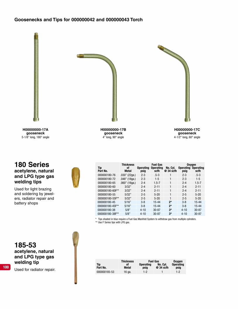
100
185-53acetylene, naturaland LPG type gaswelding tip
Used for radiator repair.
Thickness Fuel Gas OxygenTip of Operating Operating No. Cyl. Operating OperatingPart No. Metal psig scfh @ 34 scfh psig scfh000000180-76 .030” (22ga.) 2-3 .5-3 1 2-3 .5-3000000180-72 .048” (18ga.) 2-3 1-5 1 2-3 1-5000000180-65 .060” (16ga.) 2-4 1.5-7 1 2-4 1.5-7000000180-60 3/32” 2-4 2-11 1 2-4 2-11000000180-60F** 3/32” 2-4 2-11 1 2-4 2-11000000180-55 5/32” 2-5 5-20 1 2-5 5-20000000180-55F** 5/32” 2-5 5-20 1 2-5 5-20000000180-45 5/16” 3-8 15-44 2* 3-8 15-44000000180-45F** 5/16” 3-8 15-44 2* 3-8 15-44000000180-38 5/8” 4-10 30-87 3* 4-10 30-87000000180-38F** 5/8” 4-10 30-87 3* 4-10 30-87
000000180-45 5/16” 3-8 15-44 2* 3-8 15-44000000180-45F** 5/16” 3-8 15-44 2* 3-8 15-44000000180-38 5/8” 4-10 30-87 3* 4-10 30-87000000180-38F** 5/8” 4-10 30-87 3* 4-10 30-87
* Tips shaded in blue require a Fuel Gas Manifold System to withdraw gas from multiple cylinders.** Use F Series tips with LPG gas.
Thickness Fuel Gas OxygenTip of Operating No. Cyl. OperatingPart No. Metal psig @ 34 scfh psig000000185-53 16 ga. 1-2 1 1-2
H00000000-17Agooseneck
5-1/8” long, 180° angle
H00000000-17Bgooseneck
4” long, 90° angle
H00000000-17Cgooseneck
4-1/2” long, 60° angle
Goosenecks and Tips for 000000042 and 000000043 Torch
180 Seriesacetylene, naturaland LPG type gaswelding tips
Used for light brazingand soldering by jewel-ers, radiator repair andbattery shops
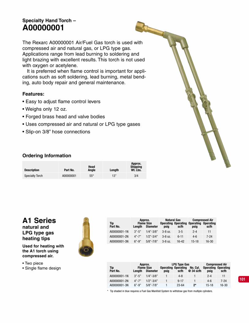
Specialty Hand Torch –
A00000001
The Rexarc A00000001 Air/Fuel Gas torch is used withcompressed air and natural gas, or LPG type gas.Applications range from lead burning to soldering andlight brazing with excellent results. This torch is not usedwith oxygen or acetylene.
It is preferred when flame control is important for appli-cations such as soft soldering, lead burning, metal bend-ing, auto body repair and general maintenance.
Features:
• Easy to adjust flame control levers
• Weighs only 12 oz.
• Forged brass head and valve bodies
• Uses compressed air and natural or LPG type gases
• Slip-on 3/8” hose connections
Approx.Head Shipping
Description Part No. Angle Length Wt. Lbs.
Specialty Torch A00000001 55° 13” 3/4
Ordering Information
A1 Seriesnatural andLPG type gasheating tips
Used for heating withthe A1 torch usingcompressed air.
• Two piece• Single flame design
Approx. LPG Type Gas Compressed AirTip Flame Size Operating Operating No. Cyl. Operating OperatingPart No. Length Diameter psig scfh @ 34 scfh psig scfh
A00000001-1N 3”-5” 1/4”-3/8” 1 4-8 1 2-4 11
A00000001-2N 4”-7” 1/2”-3/4” 1 9-17 1 4-6 7-24
A00000001-3N 6”-9” 5/8”-7/8” 1 23-64 2* 15-18 16-30
* Tip shaded in blue requires a Fuel Gas Manifold System to withdraw gas from multiple cylinders.
Approx. Natural Gas Compressed AirTip Flame Size Operating Operating Operating OperatingPart No. Length Diameter psig scfh psig scfh
A00000001-1N 3”-5” 1/4”-3/8” 3-8 oz. 3-5 2-4 11
A00000001-2N 4”-7” 1/2”-3/4” 3-8 oz. 6-11 4-6 7-24
A00000001-3N 6”-9” 5/8”-7/8” 3-8 oz. 16-42 15-18 16-30
A00000001-3N 6”-9” 5/8”-7/8” 1 23-64 2* 15-18 16-30
101

000004360AGas EconomizerAn automatic shutoff valve thatsaves gas and time.
To shut off gas supply to the torch, justhang it on the handle. To restart, lift thetorch off the handle and re-ignite it withthe pilot flame. The Economizer elimi-nates repeated adjustment of the torchvalves.
Features:
• Easy to operate – torch weight shutsoff the gas
• No need to re-adjust gas controlknobs on the torch
• Used with all fuel gases
Bracket for benchmounting is optional
Approx.Shipping
Description Part No. Wt. Lbs.
Gas Economizer with Acetylene pilot base, less bracket 000004360A 4
Optional pilot base for Natural and LPG type fuel gas 000004360-24 1/2
Optional bracket for bench mounting 000003360-21 1/2
Ordering Information
102

103
L I M I T E D W A R R A N T Y
(1) Rexarc International, Inc. (“Rexarc”) warrants that the products purchased from Rexarc (the“Products”) are free from defects in material and workmanship. This warranty is given only to theoriginal purchaser from Rexarc. The duration of this warranty is ninety (90) days for electricalcomponents and one year for other parts and components, in each case starting from the dateof shipment to the original purchaser.
(2) Rexarc’s liability in connection with this warranty or other claim relating to the Products shall belimited to the repair, or at Rexarc’s option, the replacement or refund of the purchase price, of anyProduct that is returned to Rexarc in West Alexandria, Ohio, freight prepaid, and is determined tobe defective after examination by Rexarc. No product or parts or components may be returned toRexarc without first receiving return authorization from Rexarc. Products or parts or componentsthereof which are repaired or replaced by Rexarc will be returned to the purchaser freight collect.
(3) Rexarc does not warrant any Product, components or parts not manufactured by Rexarc. Also,the Rexarc warranty does not apply to defects or damage caused by or arising from: (a) use of aProduct for purposes other than those for which it was designed, (b) improper installation, (c)accidents or disasters such as fire or flood, (d) unauthorized attachments or modification, (e)shipment, (f) normal wear or tear, or (g) any abuse or misuse of the Product.
(4) EXCEPT AS EXPRESSLY STATED HEREIN, REXARC MAKES NO WARRANTY, EXPRESS ORIMPLIED, WHETHER OF MERCHANTABILITY OR FITNESS FOR ANY PARTICULAR PUR-POSE OR USE OR OTHERWISE, ON THE PRODUCTS, OR ON ANY PARTS OR LABOR FUR-NISHED DURING THE SALE, DELIVERY OR SERVICING OF THE PRODUCTS.
(5) This warranty is not intended to cover consumer products, as defined in the Magnuson-MossWarranty-Federal Trade Commission Improvement Act, which are purchased by the purchaser forpurposes other than resale. If the purchaser does not intend to resell the Products, and if theProducts are consumer products as defined in the Magnuson-Moss Act, the foregoing warranty,but not the limitation of Rexarc’s liability, shall be null and void.
(6) Any action for breach of this warranty must be commenced within 15 months following shipmentof the Product to the original purchaser.
(7) IN NO EVENT SHALL REXARC BE LIABLE TO THE PURCHASER FOR ANY SPECIAL, INDI-RECT, INCIDENTAL OR CONSEQUENTIAL DAMAGES ARISING OUT OF, OR AS THERESULT OF, THE SALE, DELIVERY, NON-DELIVERY, SERVICING, USE OR LOSS OF USE OFTHE PRODUCTS OR ANY PART THEREOF, OR FOR ANY CHARGES OR EXPENSES OF ANYNATURE INCURRED WITHOUT REXARC’S WRITTEN CONSENT, REGARDLESS OFWHETHER SUCH CLAIM THEREFOR IS BASED UPON BREACH OF WARRANTY, BREACHOF CONTRACT, NEGLIGENCE, STRICT TORT OR ANY OTHER LEGAL THEORY. IN NOEVENT SHALL REXARC’S LIABILITY UNDER ANY CLAIM MADE BY THE PURCHASEREXCEED THE PURCHASE PRICE OF THE PRODUCTS IN RESPECT OF WHICH DAMAGESARE CLAIMED.
(8) Some states do not allow limits on warranties or on remedies for breach in certain transactions.In such states, the limits in paragraphs (4) and (7) may not apply.