T4/A4 EOM - PSG
31
EOM Simplify your process Engineering Operation & Maintenance Original ™ Series PLASTIC Pumps T4/A4 WIL-10220-E-02 REPLACES EOM T4/A4P 5/05
Transcript of T4/A4 EOM - PSG

EOM
S i m p l i f y y o u r p r o c e s s
E n g i n e e r i n g O p e r a t i o n &M a i n t e n a n c eOriginal™ Series PLASTIC Pumps
T4/A4
WIL-10220-E-02REPLACES EOM T4/A4P 5/05

TABLE OF CONTENTSPAGE #
SECTION 1 — CAUTIONS ............................................................................................ 1
SECTION 2 — PUMP DESIGNATION SYSTEM ......................................... 2
SECTION 3 — HOW IT WORKS (PUMP & AIR SYSTEMS) ............ 3
SECTION 4 — DIMENSIONAL DRAWINGS A. T4 PLASTIC and UItrapure Air-Operated........................................................................... 4 B. A4 PLASTIC Accu-Flo™ .................................................................................................... 4
SECTION 5 — PERFORMANCE CURVES A. T4 PLASTIC Rubber-Fitted ................................................................................................ 5 B. T4 PLASTIC Ultra-Flex™-Fitted ......................................................................................... 5 C. T4 PLASTIC TPE-Fitted ..................................................................................................... 6 D. T4 PLASTIC PTFE-Fitted ................................................................................................... 6 E. A4 PLASTIC Accu-Flo™ TPE-Fitted .................................................................................. 7 F. A4 PLASTIC Accu-Flo™ TPE-Fitted 70/30 Operating Condition ...................................... 7 G. A4 PLASTIC Accu-Flo™ PTFE-Fitted ................................................................................ 8 H. A4 PLASTIC Accu-Flo™ PTFE-Fitted 70/30 Operating Condition .................................... 8
SECTION 6 — SUCTION LIFT CURVES & DATA A. T4 PLASTIC Air-Operated .................................................................................................. 9 B. A4 PLASTIC Accu-Flo™ .................................................................................................... 9
SECTION 7 — INSTALLATION & OPERATION A. Installation — Turbo-Flo™ Suggested Installation Drawing .............................................. 10 B. Air-Controlled Operation & Maintenance ........................................................................... 11 C. Principles Behind Accu-Flo™ Pumps................................................................................ 12 D. Installation — Accu-Flo™ Pumps ...................................................................................... 12 E. Accu-Flo™ Operation & Maintenance ............................................................................... 13 F. Troubleshooting — Turbo-Flo™ Pumps ............................................................................ 14 G. Troubleshooting — Accu-Flo™ Pumps ............................................................................. 14
SECTION 8 — DIRECTIONS FOR DISASSEMBLY/REASSEMBLY A. T4 PLASTIC Wetted Path — Tools Required, Torque Specs, Cautions ............................ 15 B. Turbo-Flo™ Air Valve — Disassembly, Cleaning, Inspection ............................................ 18 C. Reassembly Hints & Tips ................................................................................................... 20 D. Gasket Kit Installation ........................................................................................................ 21
SECTION 9 — EXPLODED VIEW/PARTS LISTING A. T4 PLASTIC Rubber/TPE-Fitted ........................................................................................ 22 B. T4 PLASTIC and Ultrapure PTFE-Fitted ............................................................................ 24 C. A4 PLASTIC Accu-Flo™ .................................................................................................... 26
SECTION 10 — REFERENCE A. Air-Operated Elastomer Options ........................................................................................ 28 B. Accu-Flo™ Electrical Reference ........................................................................................ 28
Cla
ss
I &II Ozone
Depleting Substanc
esNON
USEU.S. Clean Air Act
Amendments of 1990

1 WILDEN PUMP & ENGINEERING, LLCWIL-10220-E-02
SECTION 1
T4 PLASTICCAUTIONS – READ FIRST!
TEMPERATURE LIMITS: Polypropylene 0°C to 79°C 32°F to 175°F PVDF –12°C to 107°C 10°F to 225°F PTFE PFA –28.9°C to 107°C –20°F to 225°F Neoprene –17.8°C to 93.3°C 0°F to 200°F Buna-N® –12.2°C to 82.2°C 10°F to 180°F EPDM –51.1°C to 137.8°C –60°F to 280°F Viton® –40°C to 176.7°C –40°F to 350°F Wil-Flex™ –40°C to 107.2°C –40°F to 225°F Polyurethane 12.2°C to 65.6°C 10°F to 150°F Saniflex™ –28.9°C to 104.4°C –20°F to 220°F PTFE 4.4°C to 104.4°C 40°F to 220°F
CAUTION: When choosing pump materials, be sure to check the temperature limits for all wetted compo-nents. Example: Viton® has a maximum limit of 176.7°C (350°F) but polypropylene has a maximum limit of only 79°C (175°F).
CAUTION: Maximum temperature limits are based upon mechanical stress only. Certain chemicals will significantly reduce maximum safe operating tempera-tures. Consult engineering guide for chemical compat-ibility and temperature limits.
CAUTION: Always wear safety glasses when operat-ing pump. If diaphragm rupture occurs, material being pumped may be forced out air exhaust.
WARNING: Prevention of static sparking — If static sparking occurs, fire or explosion could result. Pump, valves, and containers must be properly grounded when handling flammable fluids and whenever discharge of static electricity is a hazard.
CAUTION: Do not exceed 8.6 bar (125 psig) air supply pressure.
CAUTION: “Champ” series pumps are made of virgin plastic and are not UV stabilized. Direct sunlight for prolonged periods can cause deterioration of plastics.
CAUTION: Before any maintenance or repair is attempted, the compressed air line to the pump should be disconnected and all air pressure allowed to bleed from pump. Disconnect all intake, discharge and air lines. Drain the pump by turning it upside down and allowing any fluid to flow into a suitable container.
CAUTION: Blow out air line for 10 to 20 seconds before attaching to pump to make sure all pipe line debris is clear. Use an in-line air filter. A 5µ (micron) air filter is recommended.
NOTE: Tighten clamp bands and retainers prior to installation. Fittings may loosen during transportation.
NOTE: When installing PTFE diaphragms, it is impor-tant to tighten outer pistons simultaneously (turning in opposite directions) to ensure tight fit.
NOTE: Before starting disassembly, mark a line from each liquid chamber to its corresponding air chamber. This line will assist in proper alignment during reas-sembly.
CAUTION: Verify the chemical compatibility of the process and cleaning fluid to the pump’s component materials in the Chemical Resistance Guide (see E4).
CAUTION: When removing the end cap using compressed air, the air valve end cap may come out with considerable force. Hand protection such as a padded glove or rag should be used to capture the end cap.
NOTE: Non lube-free pumps must be lubricated. Wilden suggests an arctic 5 weight oil (ISO grade 15). Do not over-lubricate air supply. Over-lubrication will reduce pump performance.
CAUTION: Only explosion proof (NEMA 7) solenoid valves should be used in areas where explosion proof equipment is required.
2WILDEN PUMP & ENGINEERING, LLC WIL-10220-E-02
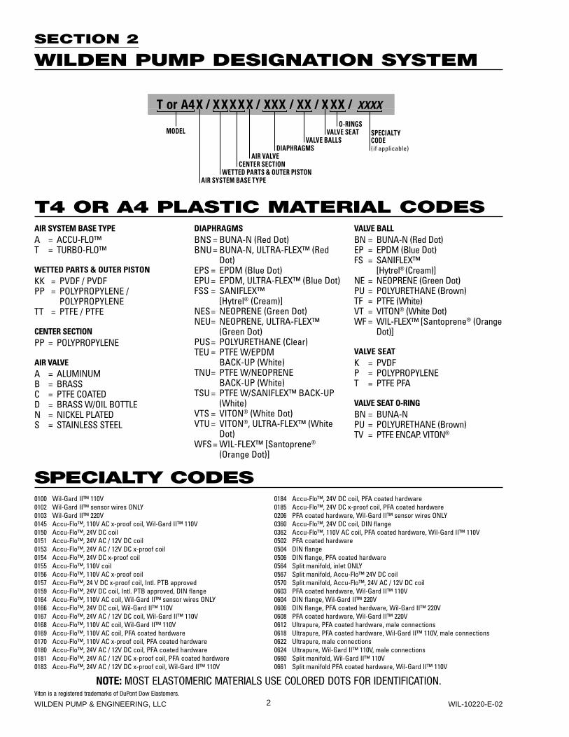
SECTION 2
WILDEN PUMP DESIGNATION SYSTEM
NOTE: MOST ELASTOMERIC MATERIALS USE COLORED DOTS FOR IDENTIFICATION.Viton is a registered trademarks of DuPont Dow Elastomers.
T4 OR A4 PLASTIC MATERIAL CODES
SPECIALTY CODES
AIR SYSTEM BASE TYPEA = ACCU-FLO™T = TURBO-FLO™
WETTED PARTS & OUTER PISTONKK = PVDF / PVDFPP = POLYPROPYLENE /
POLYPROPYLENETT = PTFE / PTFE
CENTER SECTIONPP = POLYPROPYLENE
AIR VALVEA = ALUMINUMB = BRASSC = PTFE COATEDD = BRASS W/OIL BOTTLEN = NICKEL PLATEDS = STAINLESS STEEL
DIAPHRAGMSBNS = BUNA-N (Red Dot)BNU = BUNA-N, ULTRA-FLEX™ (Red
Dot)EPS = EPDM (Blue Dot)EPU = EPDM, ULTRA-FLEX™ (Blue Dot)FSS = SANIFLEX™
[Hytrel® (Cream)]NES = NEOPRENE (Green Dot)NEU = NEOPRENE, ULTRA-FLEX™
(Green Dot)PUS = POLYURETHANE (Clear)TEU = PTFE W/EPDM BACK-UP (White)TNU = PTFE W/NEOPRENE BACK-UP (White)TSU = PTFE W/SANIFLEX™ BACK-UP
(White)VTS = VITON® (White Dot)VTU = VITON®, ULTRA-FLEX™ (White
Dot)WFS = WIL-FLEX™ [Santoprene®
(Orange Dot)]
VALVE BALLBN = BUNA-N (Red Dot)EP = EPDM (Blue Dot)FS = SANIFLEX™
[Hytrel® (Cream)]NE = NEOPRENE (Green Dot)PU = POLYURETHANE (Brown)TF = PTFE (White)VT = VITON® (White Dot)WF = WIL-FLEX™ [Santoprene® (Orange
Dot)]
VALVE SEATK = PVDFP = POLYPROPYLENET = PTFE PFA
VALVE SEAT O-RINGBN = BUNA-NPU = POLYURETHANE (Brown)TV = PTFE ENCAP. VITON®
0100 Wil-Gard II™ 110V0102 Wil-Gard II™ sensor wires ONLY0103 Wil-Gard II™ 220V0145 Accu-Flo™, 110V AC x-proof coil, Wil-Gard II™ 110V0150 Accu-Flo™, 24V DC coil0151 Accu-Flo™, 24V AC / 12V DC coil0153 Accu-Flo™, 24V AC / 12V DC x-proof coil0154 Accu-Flo™, 24V DC x-proof coil0155 Accu-Flo™, 110V coil0156 Accu-Flo™, 110V AC x-proof coil0157 Accu-Flo™, 24 V DC x-proof coil, Intl. PTB approved0159 Accu-Flo™, 24V DC coil, Intl. PTB approved, DIN flange0164 Accu-Flo™, 110V AC coil, Wil-Gard II™ sensor wires ONLY0166 Accu-Flo™, 24V DC coil, Wil-Gard II™ 110V0167 Accu-Flo™, 24V AC / 12V DC coil, Wil-Gard II™ 110V0168 Accu-Flo™, 110V AC coil, Wil-Gard II™ 110V0169 Accu-Flo™, 110V AC coil, PFA coated hardware0170 Accu-Flo™, 110V AC x-proof coil, PFA coated hardware0180 Accu-Flo™, 24V AC / 12V DC coil, PFA coated hardware0181 Accu-Flo™, 24V AC / 12V DC x-proof coil, PFA coated hardware0183 Accu-Flo™, 24V AC / 12V DC x-proof coil, Wil-Gard II™ 110V
0184 Accu-Flo™, 24V DC coil, PFA coated hardware0185 Accu-Flo™, 24V DC x-proof coil, PFA coated hardware0206 PFA coated hardware, Wil-Gard II™ sensor wires ONLY0360 Accu-Flo™, 24V DC coil, DIN flange0362 Accu-Flo™, 110V AC coil, PFA coated hardware, Wil-Gard II™ 110V0502 PFA coated hardware0504 DIN flange0506 DIN flange, PFA coated hardware0564 Split manifold, inlet ONLY0567 Split manifold, Accu-Flo™ 24V DC coil0570 Split manifold, Accu-Flo™, 24V AC / 12V DC coil0603 PFA coated hardware, Wil-Gard II™ 110V0604 DIN flange, Wil-Gard II™ 220V0606 DIN flange, PFA coated hardware, Wil-Gard II™ 220V0608 PFA coated hardware, Wil-Gard II™ 220V0612 Ultrapure, PFA coated hardware, male connections0618 Ultrapure, PFA coated hardware, Wil-Gard II™ 110V, male connections0622 Ultrapure, male connections0624 Ultrapure, Wil-Gard II™ 110V, male connections0660 Split manifold, Wil-Gard II™ 110V0661 Split manifold PFA coated hardware, Wil-Gard II™ 110V
T or A4X / XXXXX / XXX / XX / X XX / XXXX
O-RINGSMODEL VALVE SEAT
VALVE BALLSDIAPHRAGMS
AIR VALVECENTER SECTION
WETTED PARTS & OUTER PISTONAIR SYSTEM BASE TYPE
SPECIALTYCODE(if applicable)
3 WILDEN PUMP & ENGINEERING, LLCWIL-10220-E-02
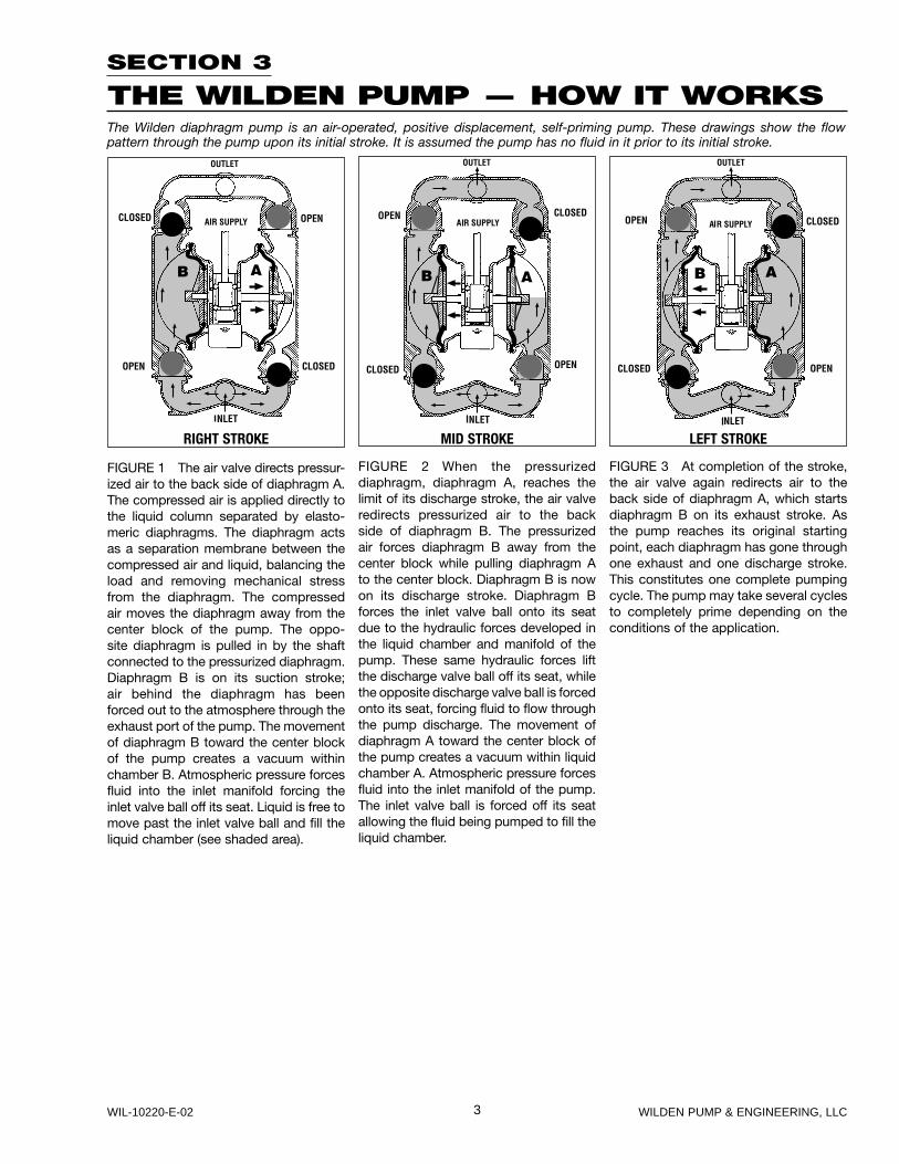
SECTION 3
THE WILDEN PUMP — HOW IT WORKSThe Wilden diaphragm pump is an air-operated, positive displacement, self-priming pump. These drawings show the flow pattern through the pump upon its initial stroke. It is assumed the pump has no fluid in it prior to its initial stroke.
FIGURE 1 The air valve directs pressur-ized air to the back side of diaphragm A. The compressed air is applied directly to the liquid column separated by elasto-meric diaphragms. The diaphragm acts as a separation membrane between the compressed air and liquid, balancing the load and removing mechanical stress from the diaphragm. The compressed air moves the diaphragm away from the center block of the pump. The oppo-site diaphragm is pulled in by the shaft connected to the pressurized diaphragm. Diaphragm B is on its suction stroke; air behind the diaphragm has been forced out to the atmosphere through the exhaust port of the pump. The movement of diaphragm B toward the center block of the pump creates a vacuum within chamber B. Atmospheric pressure forces fluid into the inlet manifold forcing the inlet valve ball off its seat. Liquid is free to move past the inlet valve ball and fill the liquid chamber (see shaded area).
FIGURE 2 When the pressurized diaphragm, diaphragm A, reaches the limit of its discharge stroke, the air valve redirects pressurized air to the back side of diaphragm B. The pressurized air forces diaphragm B away from the center block while pulling diaphragm A to the center block. Diaphragm B is now on its discharge stroke. Diaphragm B forces the inlet valve ball onto its seat due to the hydraulic forces developed in the liquid chamber and manifold of the pump. These same hydraulic forces lift the discharge valve ball off its seat, while the opposite discharge valve ball is forced onto its seat, forcing fluid to flow through the pump discharge. The movement of diaphragm A toward the center block of the pump creates a vacuum within liquid chamber A. Atmospheric pressure forces fluid into the inlet manifold of the pump. The inlet valve ball is forced off its seat allowing the fluid being pumped to fill the liquid chamber.
FIGURE 3 At completion of the stroke, the air valve again redirects air to the back side of diaphragm A, which starts diaphragm B on its exhaust stroke. As the pump reaches its original starting point, each diaphragm has gone through one exhaust and one discharge stroke. This constitutes one complete pumping cycle. The pump may take several cycles to completely prime depending on the conditions of the application.
RIGHT STROKE MID STROKE LEFT STROKE
4WILDEN PUMP & ENGINEERING, LLC WIL-10220-E-02
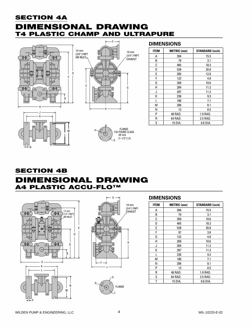
SECTION 4A
DIMENSIONAL DRAWINGT4 PLASTIC CHAMP AND ULTRAPURE
SECTION 4B
DIMENSIONAL DRAWINGA4 PLASTIC ACCU-FLO™
0 1
DIMENSIONS
ITEM METRIC (mm) STANDARD (inch)
A 394 15.5B 79 3.1C 465 18.3D 528 20.8E 305 12.0F 122 4.8G 269 10.6H 284 11.2J 287 11.3K 236 9.3L 180 7.1M 206 8.1N 13 0.5P 48 RAD. 1.9 RAD.R 64 RAD. 2.5 RAD.S 15 DIA. 0.6 DIA.
DIMENSIONS
ITEM METRIC (mm) STANDARD (inch)
A 394 15.5B 79 3.1C 269 10.6D 465 18.3E 528 20.8F 97 3.8G 122 4.8H 269 10.6J 284 11.2K 287 11.3L 236 9.3M 180 7.1N 206 8.1P 13 0.5R 48 RAD. 1.9 RAD.S 64 RAD. 2.5 RAD.T 15 DIA. 0.6 DIA.

5 WILDEN PUMP & ENGINEERING, LLCWIL-10220-E-02
SECTION 5B
PERFORMANCE CURVEST4 PLASTIC ULTRA-FLEX™-FITTEDHeight .................................. 528 mm (20.8")Width ................................... 394 mm (15.5")Depth .................................. 284 mm (11.2")Est. Ship Weight ........Polypropylene 17 kg (38 lbs)Air Inlet ....................................10 mm (3/8")Inlet ..................................... 38 mm (1-1/2")Outlet .................................. 38 mm (1-1/2")Suction Lift ......................... 4.88 m Dry (16')
8.23 m Wet (27')Displacement per Stroke ........................... 0.68 l (0.18 gal.)1
Max. Flow Rate ................. 235 lpm (62 gpm)Max. Size Solids ...................4.8 mm (3/16")1Displacement per stroke was calculated at 4.8 bar (70 psig) air inlet pressure against a 2 bar (30 psig) head pressure.
Example: To pump 132.5 lpm (35 gpm) against a discharge pressure head of 2.7 bar (40 psig) requires 4.1 bar (60 psig) and 51 Nm3/h (30 scfm) air consumption. (See dot on chart.)
Caution: Do not exceed 8.6 bar (125 psig) air supply pressure.
Flow rates indicated on chart were determined by pumping water.
For optimum life and performance, pumps should be specified so that daily operation parameters will fall in the center of the pump performance curve.
SECTION 5A
PERFORMANCE CURVEST4 PLASTIC RUBBER-FITTEDHeight .................................. 528 mm (20.8")Width ................................... 394 mm (15.5")Depth .................................. 284 mm (11.2")Est. Ship Weight ........Polypropylene 17 kg (38 lbs)Air Inlet ....................................10 mm (3/8")Inlet ..................................... 38 mm (1-1/2")Outlet .................................. 38 mm (1-1/2")Suction Lift ......................... 5.49 m Dry (18')
8.53 m Wet (28')Displacement per Stroke ........................... 1.02 l (0.27 gal.)1
Max. Flow Rate ................. 288 lpm (76 gpm)Max. Size Solids ...................4.8 mm (3/16")1Displacement per stroke was calculated at 4.8 bar (70 psig) air inlet pressure against a 2 bar (30 psig) head pressure.
Example: To pump 159 lpm (42 gpm) against a discharge pressure head of 2.7 bar (40 psig) requires 4.1 bar (60 psig) and 40.8 Nm3/h (24 scfm) air consumption. (See dot on chart.)
Caution: Do not exceed 8.6 bar (125 psig) air supply pressure.
Flow rates indicated on chart were determined by pumping water.
For optimum life and performance, pumps should be specified so that daily operation parameters will fall in the center of the pump performance curve.

6WILDEN PUMP & ENGINEERING, LLC WIL-10220-E-02
SECTION 5C
PERFORMANCE CURVEST4 PLASTIC TPE-FITTEDHeight .................................. 528 mm (20.8")Width ................................... 394 mm (15.5")Depth .................................. 284 mm (11.2")Est. Ship Weight ........Polypropylene 17 kg (38 lbs)Air Inlet ....................................10 mm (3/8")Inlet ..................................... 38 mm (1-1/2")Outlet .................................. 38 mm (1-1/2")Suction Lift ......................... 4.27 m Dry (14')
8.23 m Wet (27')Displacement per Stroke ......................... 1.17 l (0.31 gal.)1
Max. Flow Rate ................. 307 lpm (81 gpm)Max. Size Solids ...................4.8 mm (3/16")1Displacement per stroke was calculated at 4.8 bar (70 psig) air inlet pressure against a 2 bar (30 psig) head pressure.
Example: To pump 143.9 lpm (38 gpm) against a discharge pressure head of 2.7 bar (40 psig) requires 4.1 bar (60 psig) and 35.7 Nm3/h (21 scfm) air consumption. (See dot on chart.)
Caution: Do not exceed 8.6 bar (125 psig) air supply pressure.
Flow rates indicated on chart were determined by pumping water.
For optimum life and performance, pumps should be specified so that daily operation parameters will fall in the center of the pump performance curve.
SECTION 5D
PERFORMANCE CURVEST4 PLASTIC PTFE-FITTEDHeight .................................. 528 mm (20.8")Width ................................... 394 mm (15.5")Depth .................................. 284 mm (11.2")Est. Ship Weight ........Polypropylene 17 kg (38 lbs)Air Inlet ....................................10 mm (3/8")Inlet ..................................... 38 mm (1-1/2")Outlet .................................. 38 mm (1-1/2")Suction Lift ........................... 2.74 m Dry (9')
8.53 m Wet (28')Displacement per Stroke ........................... 0.53 l (0.14 gal.)1
Max. Flow Rate ................. 235 lpm (62 gpm)Max. Size Solids ...................4.8 mm (3/16")1Displacement per stroke was calculated at 4.8 bar (70 psig) air inlet pressure against a 2 bar (30 psig) head pressure.
Example: To pump 94.6 lpm (25 gpm) against a discharge pressure head of 2.7 bar (40 psig) requires 4.1 bar (60 psig) and 51 Nm3/h (30 scfm) air consumption. (See dot on chart.)
Caution: Do not exceed 8.6 bar (125 psig) air supply pressure.
Flow rates indicated on chart were determined by pumping water.
For optimum life and performance, pumps should be specified so that daily operation parameters will fall in the center of the pump performance curve.

7 WILDEN PUMP & ENGINEERING, LLCWIL-10220-E-02
SECTION 5E
PERFORMANCE CURVESA4 PLASTIC ACCU-FLO™ TPE-FITTEDHeight .................................. 528 mm (20.8")Width ................................... 394 mm (15.5")Depth .................................. 284 mm (11.2")Est. Ship Weight ........Polypropylene 16 kg (36 lbs)
PVDF 21 kg (47 lbs)PTFE PFA 23 kg (50 lbs)
Air Inlet ....................................10 mm (3/8")Inlet ..................................... 38 mm (1-1/2")Outlet .................................. 38 mm (1-1/2")Suction Lift ......................... 3.66 m Dry (12')
8.84 m Wet (29')Displacement per Stroke ........................... 0.87 l (0.23 gal.)1
Max. Flow Rate ................. 235 lpm (62 gpm)Max. Size Solids .....................6.4 mm (1/4")1Displacement per stroke was calculated at 4.8 bar (70 psig) air inlet pressure against a 2 bar (30 psig) head pressure.
Example: To pump 90.85 lpm (24 gpm) against a discharge pressure head of 2.7 bar (40 psig) requires 4.1 bar (60 psig), 17 Nm3/h(14 scfm) air consumption, and a pump speed of 120 strokes/minute. (See dot on chart.)
Caution: Do not exceed 8.6 bar (125 psig) air supply pressure.
Flow curves are for “optimal speed” conditions only. The “optimal speed” is that speed which provides the maximum flow under a particular air and fluid pressure condition. The optimal speed varies for different fluid and air pressures. Recommendations for optimal speed can be found on the right side of the flow curve.
Flow rates indicated on chart were determined by pumping water.
For optimum life and performance, pumps should be specified so that daily operation parameters will fall in the center of the pump performance curve.
SECTION 5F
70/30 OPERATING CONDITIONA4 PLASTIC ACCU-FLO™ TPE-FITTEDThis curve demonstrates the flow created when the stroke rate is modi-fied under a static air and fluid pres-sure condition. This curve can be applied to different pressure conditions to estimate the change in flow due to stroke rate.

8WILDEN PUMP & ENGINEERING, LLC WIL-10220-E-02
SECTION 5G
PERFORMANCE CURVESA4 PLASTIC ACCU-FLO™ PTFE-FITTEDHeight .................................. 528 mm (20.8")Width ................................... 394 mm (15.5")Depth .................................. 284 mm (11.2")Est. Ship Weight ........Polypropylene 16 kg (36 lbs)
PVDF 21 kg (47 lbs)PTFE PFA 23 kg (50 lbs)
Air Inlet ....................................10 mm (3/8")Inlet ..................................... 38 mm (1-1/2")Outlet .................................. 38 mm (1-1/2")Suction Lift ........................... 2.13 m Dry (7')
8.84 m Wet (29')Displacement per Stroke ........................... 0.42 l (0.11 gal.)1
Max. Flow Rate ................. 144 lpm (38 gpm)Max. Size Solids ...................4.8 mm (3/16")1Displacement per stroke was calculated at 4.8 bar (70 psig) air inlet pressure against a 2 bar (30 psig) head pressure.
Example: To pump 38 lpm (10 gpm) against a discharge pressure head of 2.7 bar (40 psig) requires 4.1 bar (60 psig), 17 Nm3/h (10 scfm) air consumption, and a pump speed of 115 strokes/minute. (See dot on chart.)
Caution: Do not exceed 8.6 bar (125 psig) air supply pressure.
Flow curves are for “optimal speed” conditions only. The “optimal speed” is that speed which provides the maximum flow under a particular air and fluid pressure condition. The optimal speed varies for different fluid and air pressures. Recommendations for optimal speed can be found on the right side of the flow curve.
Flow rates indicated on chart were determined by pumping water.
For optimum life and performance, pumps should be specified so that daily operation parameters will fall in the center of the pump performance curve.
SECTION 5H
70/30 OPERATING CONDITIONA4 PLASTIC ACCU-FLO™ PTFE-FITTEDThis curve demonstrates the flow created when the stroke rate is modi-fied under a static air and fluid pres-sure condition. This curve can be applied to different pressure conditions to estimate the change in flow due to stroke rate.

9 WILDEN PUMP & ENGINEERING, LLCWIL-10220-E-02
Suction lift curves are calibrated for pumps operating at 305 m (1,000') above sea level. This chart is meant to be a guide only. There are many variables which can affect your pump’s operating characteristics. The number of intake
and discharge elbows, viscosity of pumping fluid, elevation (atmospheric pressure) and pipe friction loss all affect the amount of suction lift your pump will attain.
SECTION 6A – AIR-CONTROLLED
SUCTION LIFT CURVES & DATA
SECTION 6B – ACCU-FLO™
SUCTION LIFT CURVES & DATA
10WILDEN PUMP & ENGINEERING, LLC WIL-10220-E-02
SECTION 7A
INSTALLATION – T4 PLASTICAIR-OPERATED PUMPS
The Model T4 Plastic pump has a 38 mm (1-1/2") inlet and 38 mm (1-1/2") outlet and is designed for flows to 307 lpm (81 gpm). A variety of diaphragms, valve balls, valve seats, and o-rings are available to satisfy temperature, chemical compatibility, abrasion and flex concerns.
The suction pipe size should be at least 38 mm (1-1/2") diameter or larger if highly viscous material is being pumped. The suction hose must be non-collapsible, reinforced type as the T4 is capable of pulling a high vacuum. Discharge piping should be at least 38 mm (1-1/2"); larger diameter can be used to reduce friction losses. It is critical that all fittings and connections are airtight or a reduction or loss of pump suction capability will result.
For T4 Champ models, Wilden offers 150 lb. standard or metric flanges. The following details should be noted when mating these to pipe works:• A 60–80 shore gasket that covers the entire flange face
should be used.• The gasket should be between .075" and .175" thickness.• Mating flanges with flat as opposed to raised surfaces
should be used for proper mechanical sealing.• The flanges should be tightened to a minimum of 6.8 N·m
(5 ft-lbs) but no more than 13.5 N·m (10 ft-lbs).
A non-raised surfaced-flange adapter should be utilized when mating to the pump’s inlet and discharge manifolds for proper sealing.
INSTALLATION: Months of careful planning, study, and selec-tion efforts can result in unsatisfactory pump performance if installation details are left to chance.
Premature failure and long term dissatisfaction can be avoided if reasonable care is exercised throughout the installation process.
LOCATION: Noise, safety, and other logistical factors usually dictate that “utility” equipment be situated away from the production floor. Multiple installations with conflicting require-ments can result in congestion of utility areas, leaving few choices for siting of additional pumps.
Within the framework of these and other existing conditions, every pump should be located in such a way that four key factors are balanced against each other to maximum advantage.
1. ACCESS: First of all, the location should be accessible. If it’s easy to reach the pump, maintenance personnel will have an easier time carrying out routine inspections and adjust-ments. Should major repairs become necessary, ease of access can play a key role in speeding the repair process and reducing total downtime.
2. AIR SUPPLY: Every pump location should have an air line large enough to supply the volume of air necessary to achieve the desired pumping rate (see pump performance chart). Use air pressure up to a maximum of 8.6 bar (125 psig) depending upon pumping requirements.The use of an air filter before the pump will ensure that the majority of any pipeline contaminants will be eliminated. For best results, the pumps should use an air filter, regulator, and lubricator system.
3. ELEVATION: Selecting a site that is well within the pump’s suction lift capability will assure that loss-of-prime troubles will be eliminated. In addition, pump efficiency can be adversely
affected if proper attention is not given to elevation (see pump performance chart).
4. PIPING: Final determination of the pump site should not be made until the piping problems of each possible location have been evaluated. The impact of current and future installations should be considered ahead of time to make sure that inadver-tent restrictions are not created for any remaining sites.
The best choice possible will be a site involving the shortest and the straightest hook-up of suction and discharge piping. Unnecessary elbows, bends, and fittings should be avoided. Pipe sizes should be selected so as to keep friction losses within practical limits. All piping should be supported inde-pendently of the pump. In addition, it should line up without placing stress on the pump fittings.
Expansion joints can be installed to aid in absorbing the forces created by the natural reciprocating action of the pump. If the pump is to be bolted down to a solid foundation, a mounting pad placed between the pump and foundation will assist in minimizing pump vibration. Flexible connections between the pump and rigid piping will also assist in minimiz-ing pump vibration. If quick-closing valves are installed at any point in the discharge system, or if pulsation within a system becomes a problem, a surge suppressor should be installed to protect the pump, piping and gauges from surges and water hammer.
When pumps are installed in applications involving flooded suction or suction head pressures, a gate valve should be installed in the suction line to permit closing of the line for pump service.
The T4 can be used in submersible applications only when both wetted and non-wetted portions are com patible with the mate-rial being pumped. If the pump is to be used in a submersible application, a hose should be attached to the pump’s air exhaust and the exhaust air piped above the liquid level.
If the pump is to be used in a self-priming application, be sure that all connections are airtight and that the suction lift is within the pump’s ability. Note: Materials of construction and elastomer material have an effect on suction lift parameters. Please refer to pump performance data.
Pumps in service with a positive suction head are most effi-cient when inlet pressure is limited to 0.5–0.7 bar (7–10 psig). Premature diaphragm failure may occur if positive suction is 0.8 bar (11 psig) and higher.
THE MODEL T4 WILL PASS 4.8 mm (3/16") SOLIDS. WHEN-EVER THE POSSIBILITY EXISTS THAT LARGER SOLID OBJECTS MAY BE SUCKED INTO THE PUMP, A STRAINER SHOULD BE USED ON THE SUCTION LINE.
CAUTION: DO NOT EXCEED 8.6 BAR (125 PSIG) AIR SUPPLY PRESSURE.
PUMPS SHOULD BE THOROUGHLY FLUSHED WITH WATER BEFORE INSTALLING INTO PROCESS LINES. FDA AND USDA PUMPS SHOULD BE CLEANED AND/OR SANITIZED BEFORE USE ON EDIBLE PRODUCTS.
BLOW OUT AIR LINE FOR 10 TO 20 SECONDS BEFORE ATTACHING TO PUMP TO MAKE SURE ALL PIPE LINE DEBRIS IS CLEAR. ALWAYS USE AN IN-LINE AIRFILTER.

11 WILDEN PUMP & ENGINEERING, LLCWIL-10220-E-02
SUGGESTED INSTALLATION
SECTION 7B – AIR OPERATION
SUGGESTED OPERATION ANDMAINTENANCE INSTRUCTIONSOPERATION: Pump discharge rate can be controlled by limiting the volume and/or pressure of the air supply to the pump (preferred method). An air regulator is used to regulate air pressure. A needle valve is used to regulate volume. Pump discharge rate can also be controlled by throttling the pump discharge by partially closing a valve in the discharge line of the pump. This action increases friction loss which reduces flow rate. This is useful when the need exists to control the pump from a remote location. When the pump discharge pressure equals or exceeds the air supply pressure, the pump will stop; no bypass or pressure relief valve is needed, and pump damage will not occur. The pump has reached a “deadhead” situation and can be restarted by reducing the fluid discharge pressure or increasing the air inlet pres-sure. The Wilden T4 pump runs solely on compressed air and does not generate heat, therefore your process fluid temperature will not be affected.
RECORDS: When service is required, a record should be made of all necessary repairs and replacements. Over a period of time, such records can become a valuable tool for predicting and preventing future maintenance problems and unscheduled downtime. In addition, accurate records make it possible to identify pumps that are poorly suited to their applications.
MAINTENANCE AND INSPECTIONS: Since each applica-tion is unique, maintenance schedules may be different for every pump. Frequency of use, line pressure, viscosity and abrasiveness of process fluid all affect the parts life of a Wilden pump. Periodic inspections have been found to offer the best means for preventing unscheduled pump downtime. Personnel familiar with the pump’s construction and service should be informed of any abnormalities that are detected during operation.
AIR OPERATED PUMPS: To stop the pump from operating in an emergency situation, simply close the shut-off valve (user supplied) installed in the air supply line. A properly functioning valve will stop the air supply to the pump, therefore stopping output. This shut-off valve should be located far enough away from the pumping equipment such that it can be reached safely in an emergency situation.
ACCU-FLO™ PUMPS: Accu-Flo™ pumps function with solenoid valves and require an electrical control circuit to supply pulses. Under normal operating conditions, the control circuit is sufficient for starting and stopping the pump. However, the shut-off valve (user supplied) installed in the air supply line can be used to stop the pump if necessary. Therefore, it should be located far enough away from the pumping equipment such that it can be reached safely in an emergency situation.
NOTE: In the event of a power failure, the shutoff valve should be closed, if the restarting of the pump is not desireable once power is regained.

12WILDEN PUMP & ENGINEERING, LLC WIL-10220-E-02
SECTION 7C
OPERATING PRINCIPLES BEHIND ACCU-FLO™ PUMPS
In Accu-Flo™ pump models, the standard air valve is replaced with a two position, four-way solenoid valve that has a single operator and spring return. The valve is internally air piloted for longer coil and operator life.
When the solenoid is unpowered, one air chamber is pressur-ized with air, while the opposite chamber is exhausted. When electric power is applied, the solenoid shifts, and the pressur-ized air chamber is exhausted while the opposite chamber is pressurized. By alternately applying and removing power, the solenoid-operated pump runs like a standard Wilden pump.
The speed of the pump is controlled electrically. Since each stroke is controlled by an electrical signal, the pump is ideal for batching and other electrically controlled dispensing applica-tions.
Although the speed of the pump is controlled electrically, the air pressure is important. Air pressure displaces the fluid, and if the pressure is insufficient to complete the physical stroke before an electronic impulse signals the pump to shift, the stroke will not be completed, and the displacement per stroke will be reduced. This does not harm the unit in any way, but it may cause inaccuracy when attempting to batch specific quantities with high precision if this effect is not taken into account.
There are three coil voltage options available. One coil allows for 24V DC operation. The second coil option allows for operation with either 12V DC or 24V AC at 60 Hz and the third coil option allows for 110V AC operation.
SECTION 7D
INSTALLATION – A4 PLASTICACCU-FLO™ PUMPSBefore installing your A4 Accu-Flo™ pump, review Section 7A for general installation suggestions including Location, Access, Air Supply, Elevation, and Piping.
The Accu-Flo™ Model A4 has a 38 mm (1-1/2") inlet and 38 mm (1-1/2") outlet and is designed for flow to 235 lpm (62 gpm). This maximum flow rate was calculated at 300 strokes per minute with 100 psig air inlet against 0 psig discharge head. The A4 Plastic pump is manufactured with wetted parts of polypropylene or PVDF. The center section of the A4 Plastic pump is of aluminum or polypropylene construction. A variety of diaphragms, valve balls, and o-rings are available to satisfy temperature, chemical compatibility, abrasion and flex concerns.
All wiring used to operate the pump should be placed and connected according to the proper electrical codes. It is important that the wiring is of adequate gauge to carry the current required to operate the pump. In addition, it is necessary that the electrical power supply is large enough to supply the current required to operate the pump. Wiring should be above ground level if possible (in case of fluid spill or leakage), and all wiring and connections which could become wet or damp should be made watertight.
If the pump is to be used in a self-priming application, be sure that all connections are airtight and that the suction lift is within the pump’s ability. Note: Materials of construction and elastomer material have an effect on suction lift parameters. Please refer to pump performance data.
Pumps in service with a positive suction head are most effi-cient when inlet pressure is limited to 0.5–0.7 bar (7–10 psig). Premature diaphragm failure may occur if positive suction head is 0.8 bar (11 psig) and higher.
The solenoid valve is rated for continuous duty; however, stopping on an even number stroke count insures that the electrical power is off when pump is stopped. This practice is safer and also eliminates unwanted strokes when the system is shut down and electrical power is off.
THE MODEL A4 WILL PASS 4.8 mm (3/16") SOLIDS. WHEN-EVER THE POSSIBILITY EXISTS THAT LARGER SOLID OBJECTS MAY BE SUCKED INTO THE PUMP, A STRAINER SHOULD BE USED ON THE SUCTION LINE.
WARNING: Before installation, consult chart in Section 10B to ensure proper electrical connection.
WARNING: The solenoid valve should not be used in an area where explosion proof equipment is required unless NEMA 7 valve is specified.
There are three coil options available in both NEMA 4 and NEMA 7 ratings. One coil allows for 110V AC operation, one allows for 24V DC operation, and the third allows for either 24V AC or 12V DC operation. See Section 10B for options and part numbers.
13 WILDEN PUMP & ENGINEERING, LLCWIL-10220-E-02
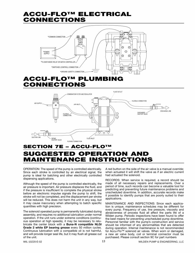
ACCU-FLO™ ELECTRICALCONNECTIONS
ACCU-FLO™ PLUMBINGCONNECTIONS
SECTION 7E – ACCU-FLO™
SUGGESTED OPERATION ANDMAINTENANCE INSTRUCTIONSOPERATION: The speed of the pump is controlled electrically. Since each stroke is controlled by an electrical signal, the pump is ideal for batching and other electrically controlled dispensing applications.
Although the speed of the pump is controlled electrically, the air pressure is important. Air pressure displaces the fluid, and if the pressure is insufficient to complete the physical stroke before an electronic impulse signals the pump to shift, the stroke will not be completed, and the displacement per stroke will be reduced. This does not harm the unit in any way, but it may cause inaccuracy when attempting to batch specific quantities with high precision.
The solenoid operated pump is permanently lubricated during assembly, and requires no additional lubrication under normal operation. If the unit runs under extreme conditions (continu-ous operation at high speeds), it may be necessary to relu-bricate the center block with a Buna-N compatible NLGI Grade 2 white EP bearing grease every 50 million cycles. Continuous lubrication with a compatible oil is not harmful, and will provide longer seal life, but it may flush all grease out of the unit.
A red button on the side of the air valve is a manual override; when actuated it will shift the valve as if an electric current had actuated the solenoid.
RECORDS: When service is required, a record should be made of all necessary repairs and replacements. Over a period of time, such records can become a valuable tool for predicting and preventing future maintenance problems and unscheduled downtime. In addition, accurate records make it possible to identify pumps that are poorly suited to their applications.
MAINTENANCE AND INSPECTIONS: Since each applica-tion is unique, maintenance schedules may be different for every pump. Frequency of use, line pressure, viscosity and abrasiveness of process fluid all affect the parts life of a Wilden pump. Periodic inspections have been found to offer the best means for preventing unscheduled pump downtime. Personnel familiar with the pump’s construction and service should be informed of any abnormalities that are detected during operation. Internal maintenance is not recommended for Accu-Flo™ solenoid air valves. When worn or damaged, a new air valve body, coil or terminal connector must be purchased. Please consult section 9C for part numbers

14WILDEN PUMP & ENGINEERING, LLC WIL-10220-E-02
SECTION 7F – AIR-CONTROLLED
TROUBLESHOOTINGPump will not run or runs slowly.1. Check air inlet screen and air filter for debris.2. Check for sticking air valve, flush air valve in solvent.3. Check for worn out air valve. If piston face in air valve is
shiny instead of dull, air valve is probably worn beyond working tolerances and must be replaced.
4. Check center block Glyd™ rings. If worn excessively, they will not seal and air will simply flow through pump and out air exhaust. Use only Wilden Glyd™ rings as they are of special construction.
5. Check for rotating piston in air valve.6. Check type of lubricant being used. A higher viscosity
oil than suggested may cause the piston to stick or run erratically. Wilden suggests the use of an oil with arctic characteristics (ISO 15-5 wt.).
Pump runs but little or no product flows.1. Check for pump cavitation; slow pump speed down to
match thickness of material being pumped.2. Check for sticking ball check valves. If material being
pumped is not compatible with pump elastomers, swell-
ing may occur. Replace ball check valves and o-rings with the proper elastomers.
3. Check to make sure all suction connections are air tight, especially clamp bands around intake balls.
Pump air valve freezes.Check for excessive moisture in compressed air. Either install dryer or hot air generator for compressed air.
Air bubbles in pump discharge.1. Check for ruptured diaphragm.2. Check tightness of clamp bands, especially at intake
manifold.
Product comes out air exhaust.1. Check for diaphragm rupture.2. Check tightness of piston plates to shaft.
Pump rattles.1. See E9 Troubleshooting Guide.2. Create false discharge head or suction lift.
SECTION 7G – ACCU-FLO™
TROUBLESHOOTINGPump will not run.1. Check for pressurized air at the inlet. (Min. 3.1 bar [45
psig].)2. Check air inlet and filter for debris.3. Connect a test lamp to the two wires which run to pump
and ensure that the lamp cycles on and off.4. Make sure that the air valve manual override (small red
knob on front of valve) is switched to the “0” position.5. Check pilot pressure vent at the top of the operator/coil
assembly to ensure that it is not clogged.6. Check for a worn out air valve. If air continually blows out
the exhaust in very large quantities, the air valve seals may be worn beyond their ability to function. In this case, the valve must be replaced.
NOTE: Before the valve is scrapped, it is possible that it may be saved by completely disassembling the valve, cleaning all components and relubricating the valve.
Pump runs but little or no fluid comes out.1. Check that the discharge isolation valve is not closed.2. Check that the electronic signal is slow enough that the
pump is able to complete each physical stroke before it is signaled to change direction. The time required to complete the stroke is determined by a variety of factors which include fluid viscosity and head pressure. The shaft can be viewed if the muffler is removed to verify that the pump is stroking.
3. Check for pump cavitation; slow pump speed down to match the thickness of the material being pumped.
4. Check for sticking ball check valves. If the material being pumped is not compatible with the pump elastomers, swelling may occur. Replace ball check valves and o-ring with the proper elastomers.
5. Check to make sure that all suction connections are air tight, and that the clamp bands are properly tightened.
Pump air passages blocked with ice.Check for excessive moisture in compressed air line. As the air expands out the exhaust during the operation of the pump, water vapor entrapped in the compressed air can freeze and block the air passageways in the pump. If this occurs, it may be necessary to install a coalescing filter, an air dryer, or a hot air generator for the compressed air.
Air bubbles in pump discharge.1. Check for ruptured diaphragm.2. Check tightness of clamp bands, and the integrity of the
o-rings, especially at intake manifold.
Product comes out air exhaust.1. Check for diaphragm rupture.2. Check tightness of piston plates to shaft.
Pump rattles.1. See E9 Troubleshooting Guide.2. Create false discharge head or suction lift.
Solenoid buzzes or solenoid burnout.1. Incorrect voltage, faulty or dirty solenoid.
Solenoid valve fails to shift electrically but shifts with manual override.1. Incorrect voltage, defective coil or wiring.
Solenoid valve fails to shift electrically or with manual override.1. Inadequate air supply, contamination, inadequate or
improper lubrication, mechanical binding in the valve.
Valve shifts but fails to return.1. Broken spring, mechanical binding.
Excessive leaking from air valve vent.1. Worn seals in air valve.

15 WILDEN PUMP & ENGINEERING, LLCWIL-10220-E-02
SECTION 8A
T4 PLASTICDIRECTIONS FOR DISASSEMBLY/REASSEMBLY
Figure 1
Step 2. Figure 2
Utilizing a 1/2" wrench, remove the two small clamp bands that fasten the discharge manifold to the liquid chambers.
Step 3. Figure 3
Lift away the discharge manifold to expose the valve balls and seats.
CAUTION: Before any maintenance or repair is attempted, the compressed air line to the pump should be disconnected and all air pressure allowed to bleed from the pump. Discon-nect all intake, discharge, and air lines. Drain the pump by turning it upside down and allowing any fluid to flow into a suitable container. Be aware of any hazardous effects of contact with your process fluid.
The Wilden model T4 has a 38 mm (1-1/2") inlet and outlet and is designed for flows up to 307 lpm (81 gpm). The model T4 plastic is available in polypropylene wetted parts. The air valve is manufactured of brass, PTFE-coated brass, nickel-plated brass or stainless steel. All o-rings used in the pump are of a special material and shore hardness which should only be replaced with factory-supplied parts.
TOOLS REQUIRED:1/2" Wrench3/16" Allen WrenchAdjustable WrenchVise equipped with soft jaws (such as plywood, plasticor other suitable material)
NOTE: The model used for these instructions incorporates rubber diaphragms, balls, and seats. Models with PTFE diaphragms, balls and seats are the same except where noted. The procedures for A4 Accu-Flo™ pumps are the same except for the air distribution system.
DISASSEMBLY:
Step 1.
Before starting disassembly, mark a line from each liquid chamber to its corresponding air chamber. This line will assist in proper alignment during reassembly.

16WILDEN PUMP & ENGINEERING, LLC WIL-10220-E-02
Step 4. Figure 4
Remove the discharge valve balls, o-rings and seats from the liquid chambers and inspect for nicks, gouges, chemi-cal attack or abrasive wear. Replace worn parts with genu-ine Wilden parts for reliable performance.
Step 5. Figure 5
Remove the two small clamp bands which fasten the intake manifold to the liquid chambers.
Step 6. Figure 6
Lift liquid chambers and center section from intake manifold to expose intake valve balls and seats.
Step 7. Figure 7
Remove the discharge valve balls, o-rings and seats from the liquid chambers and inspect for nicks, gouges, chemical attack or abrasive wear. Replace worn parts with genuine Wilden parts for reli-able performance.
Step 8. Figure 8
Normally inlet and discharge manifolds should not be disassembled during regular pump maintenance. Should this be necessary, completely remove clamp bands and inspect o-rings for nicks, cuts and chemical attack.

17 WILDEN PUMP & ENGINEERING, LLCWIL-10220-E-02
Step 12. Figure 12
NOTE: Due to varying torque values, one of the following two situations may occur: 1) The outer piston, diaphragm and inner piston remain attached to the shaft and the entire assembly can be removed from the center section (Figure 12). 2) The outer piston, diaphragm and inner piston separate from the shaft which remains connected to the opposite side diaphragm assembly (Figure 13). Repeat disas-sembly instructions for the opposite liquid chamber. Inspect diaphragm assembly and shaft for signs of wear or chemical attack. Replace all worn parts with genuine Wilden parts for reliable performance.
Figure 13 Step 13. Figure 14
To remove diaphragm assembly from shaft, secure shaft with soft jaws (a vise fitted with plywood or other suit-able material) to ensure shaft is not nicked, scratched, or gouged. Using an adjustable wrench or by hand, remove diaphragm assembly from shaft. Inspect all parts for wear and replace with genu-ine Wilden parts if necessary.
Step 9. Figure 9
Remove one set of large clamp bands, which secure one liquid chamber to the center section.
Step 10. Figure 10
Lift liquid chamber away from center section to expose diaphragm and outer piston.
Step 11. Figure 11
Using an adjustable wrench, or by rotat-ing the diaphragm by hand, remove the diaphragm assembly.

18WILDEN PUMP & ENGINEERING, LLC WIL-10220-E-02
The air valve assembly consists of both the air valve body and piston and the center block. The unique design of the air valve relies only on differential pressure to effect the diaphragm shift. It is reliable and simple to maintain. The bushing in the center block, along with the diaphragm shaft, provides the “trigger” to tell the air valve to shift. The following procedure will ensure that the air valve on your Wilden pump will provide longtrouble-free service.
If the piston does not move freely in the air valve, the entire air valve should be immersed in a cleaning solution. [NOTE:Do not force the piston by inserting a metal object.] This soaking should remove any accumulation of sludge and grit which is preventing the air valve piston from moving freely. Also, remove and clean the air valve screen (P/N 04-2500-03). If the air valve piston does not move freely after the above cleaning, the air valve should be disassembled as follows: Remove the snap ring from the top end of the air valve cylinder and apply an air jet to the 3/16-inch hole on the opposite end of the air valve face (see Figure C). CAUTION: The air valve end cap may come out with consid-erable force. Inspect the piston and cylinder bore for nicks and scoring.
AIR VALVE DISASSEMBLY:The air valve (P/N 04-2000-07) can be disconnected from the pump by removing the four socket head cap screws which attach it to the center block. The piston should move freely and the ports in the piston should line up with the ports on the face of the air valve body (see Figure D). Thepiston should also appear to be dull, dark gray in color. If the piston appears to be a shiny aluminum color, the air valve is probably worn beyond working tolerances and should be replaced.
Figure A
Figure B Figure C
Figure D
CENTERBLOCK
AIR FILTERSCREEN
AIR VALVEPISTON
CENTER BLOCKBUSHING
AIR INLET
END CAP
AIR VALVE ASSEMBLY
AIR VALVEBODY
SECTION 8B
AIR VALVE / CENTER BLOCKDISASSEMBLY

19 WILDEN PUMP & ENGINEERING, LLCWIL-10220-E-02
Small nicks can usually be dressed out and the piston returned to service. Inspect the cylinder end caps (P/N 04-2300-23 has the piston guide pin and P/N 04-2330-23 does not.) Make sure that the guide pin is straight and smooth or the piston will not move freely in the cylinder. Inspect the anti-centering pin holes found at the ends of the air valve piston and ensure they are free of debris. New o-rings (P/N 04-2390-52) should be installed on the end caps. Lubricate the o-rings with an arctic5 weight hydraulic oil (ISO grade 15) and install the end caps, assuring that proper alignment of the piston and cylinder ports is maintained (see Figure D). Reinstall air valve to center block of pump. Tighten per the torque specification.*
GLYD™ RING REPLACEMENT:When the Glyd™ rings become worn, they will no longer seal and must be replaced. Due to the design characteristics of the Glyd™ rings, it is suggested that you use the ringer seal installation kit when replacing Glyd™ rings.
CENTER BLOCK ASSEMBLY(P/N 04-3100-01):The pump’s center block (P/N 04-3100-01) consists of a die cast housing with a cast-in-bronze bushing (Figure G). Figure H shows T4 injection-molded polypropylene center section(P/N 04-3150-20) and alignment with air valve. The bushinghas eleven grooves cut on the inside diameter. There are seven Glyd™ rings (P/N 08-3210-55-225) that fit in these grooves (see Figure E). Since these Glyd™ rings form a part of the shifting function of the pump, it is necessary that they be located in the proper grooves. The bronze bushing is replaceable in cast iron center block only. When bush-ing wear becomes excessive, a new center block must be used.
Figure F (Side View)
Figure B
P/N 08-3210-55-225P/N 04-3800-09-07
Figure E
Grooves InBushing WhichContain Glyd™ Rings
*Refer to Section 8C for torque specifications.
Figure GCenter Block(Front View)
DRILLALIGNMENT
DRILLALIGNMENT
P/U from#71477 EOM M4PPage 19 Same Figure
Figure H
AIR VALVE PISTON CENTER BLOCK
END CAP
AIR INLET
AIR FILTER SCREEN

20WILDEN PUMP & ENGINEERING, LLC WIL-10220-E-02
SECTION 8C
REASSEMBLY HINTS & TIPS
ASSEMBLY:Upon performing applicable maintenance to the air distribu-tion system, the pump can now be reassembled. Please refer to the disassembly instructions for photos and parts placement. To reassemble the pump, follow the disassem-bly instructions in reverse order. The air distribution system needs to be assembled first, then the diaphragms and finally the wetted path. Please find the applicable torque speci-fications on this page. The following tips will assist in the assembly process.
• Clean the inside of the center section shaft bushing to ensure no damage is done to new seals.
• Stainless bolts should be lubed to reduce the possibility of seizing during tightening.
• Ensure proper alignment on the sealing surfaces of intake and discharge manifolds.
• Liquid chambers are easier to attach when the diaphragm is inverted. Prior to attaching the second water chamber, push diaphragm assembly so that it is as close as possi-ble to the center section.
• PVDF and PFA pumps require PTFE gasket kits for improved sealing. Gasket kits may be installed on other pumps where sealing is an issue.
• When assembling PTFE-coated hardware, care should be taken to keep the coating intact.
• When installing Glyd™ rings, the use of the Wilden Ringer tool simplifies seal installation.
MAXIMUM TORQUE SPECIFICATIONS
Description of Part Plastic Pumps
Air Valve 3.4 N·m [30 in-lbs]
Outer Piston 47.5 N·m [35 ft-lbs]
Small Clamp Band 9.6 N·m [85 in-lbs]
Large Clamp Band (Rubber-fi tted) 18.6 N·m [165 in-lbs]
Large Clamp Band (PTFE-fi tted) 18.6 N·m [165 in-lbs]

21 WILDEN PUMP & ENGINEERING, LLCWIL-10220-E-02
Step 1. Figure 1
Gently remove the adhesive covering from the back of the PTFE tape. Ensure that the adhesive strip remains attached to the PTFE tape.
Step 2. Figure 2
Starting at any point, place the PTFE tape in the center of the diaphragm bead groove on the liquid chamber and press lightly on the tape to ensure that the adhe-sive holds it in place during assembly. Do not stretch the tape during placement in center of diaphragm bead groove.
Step 3. Figure 3
The ends of the tape should overlap approximately 13 mm (1/2”). Proceed to install the PTFE tape on the remaining liquid chamber.
PTFE Gasket Kits (04-9501-99) are available for A4 and T4 plas-tic pumps. Carefully prepare sealing surfaces by removing all debris and foreign matter from diaphragm bead and all mating
surfaces. If necessary, smooth or deburr all sealing surfaces. Mating surfaces must be properly aligned in order to ensure positive sealing characteristics.
SECTION 8D
GASKET KIT INSTALLATION
Step 4. Figure 4
Carefully remove the protective covering from the back of the PTFE gasket attached to tape.
Step 5. Figure 5
Install the valve ball, valve seat and o-ring.
Step 6. Figure 6
Center the gasket so that it evenly covers the o-ring and seat areas.
Step 7. Figure 7
Gently apply pressure to gasket to ensure the adhesive maintains a positive seal to stay in place during pump assembly.
22WILDEN PUMP & ENGINEERING, LLC WIL-10220-E-02
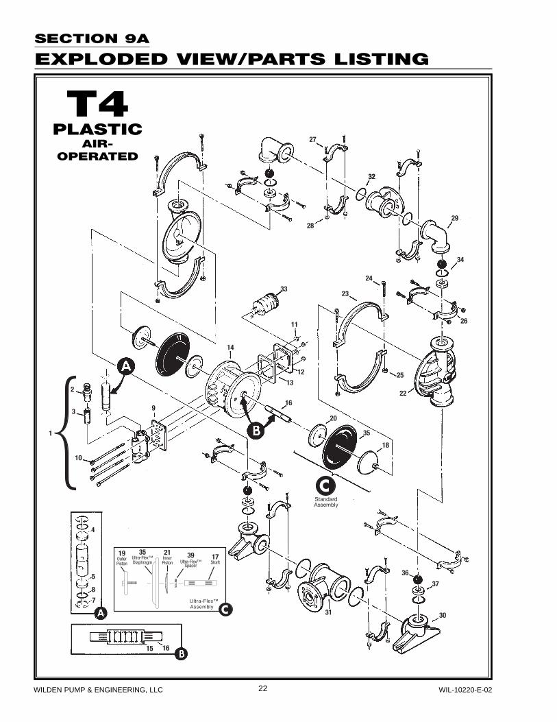
Ultra-Flex™ Assembly™
StandardAssembly
4
5
8
7
15 16
10
3
2
9
14
33
11
12
13
16
20
23
24
35
18
25
22
26
34
29
32
28
32
27
31
36
37
30
1
19OuterPiston
35Ultra-Flex™Diaphragm
21InnerPiston
39Ultra-Flex™
Spacer
17Shaft
SECTION 9A
EXPLODED VIEW/PARTS LISTING
T4PLASTIC
AIR-OPERATED
23 WILDEN PUMP & ENGINEERING, LLCWIL-10220-E-02
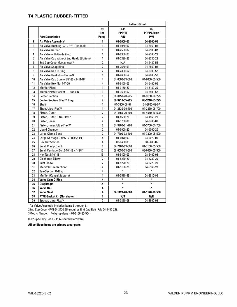
T4 PLASTIC RUBBER-FITTED
Rubber-Fitted
Part Description
Qty. Per
Pump
T4/PPPPB
P/N
T4/PPPPC/0502
P/N1 Air Valve Assembly1 1 04-2000-07 04-2000-052 Air Valve Bushing 1⁄2" x 3⁄8" (Optional) 1 04-6950-07 04-6950-053 Air Valve Screen 1 04-2500-07 04-2500-074 Air Valve with Guide (Top) 1 04-2300-23 04-2300-235 Air Valve Cap without End Guide (Bottom) 1 04-2330-23 04-2330-236 End Cap Cover (Not shown)2 2 N/A 04-2420-557 Air Valve Snap Ring 2 04-2650-03 04-2650-038 Air Valve Cap O-Ring 2 04-2390-52 04-2390-529 Air Valve Gasket — Buna-N 1 04-2600-52 04-2600-52
10 Air Valve Cap Screw 1⁄4"-20 x 6-11⁄16" 4 04-6000-03-500 04-6000-05-50011 Air Valve Hex Nut 1⁄4"-20 4 04-6400-03 04-6400-0512 Muffler Plate 1 04-3180-20 04-3180-2013 Muffler Plate Gasket — Buna-N 1 04-3500-52 04-3500-5214 Center Section 1 04-3150-20-225 04-3150-20-22515 Center Section Glyd™ Ring 7 08-3210-55-225 08-3210-55-22516 Shaft 1 04-3800-09-07 04-3800-09-0717 Shaft, Ultra-Flex™ 1 04-3830-09-700 04-3830-09-70018 Piston, Outer 2 04-4550-20-500 04-4550-20-50019 Piston, Outer, Ultra-Flex™ 2 04-4560-21 04-4560-2120 Piston, Inner 2 04-3700-08 04-3700-0821 Piston, Inner, Ultra-Flex™ 2 04-3760-01-700 04-3760-01-70022 Liquid Chamber 2 04-5000-20 04-5000-2023 Large Clamp Band 2 04-7300-03-500 04-7300-05-50024 Large Carriage Bolt 5⁄16"-18 x 2-1⁄4" 4 04-6070-03 04-6070-0525 Hex Nut 5⁄16"-18 4 08-6400-03 08-6400-0526 Small Clamp Band 8 04-7100-03-500 04-7100-05-50027 Small Carriage Bolt 5⁄16"-18 x 1-3⁄4" 16 08-6050-03-500 08-6050-05-50028 Hex Nut 5⁄16"-18 16 08-6400-03 08-6400-0529 Discharge Elbow 2 04-5230-20 04-5230-2030 Inlet Elbow 2 04-5220-20 04-5220-2031 Manifold Tee Section3 2 04-5160-20 04-5160-2032 Tee-Section O-Ring 4 * *33 Muffler (Consult factory) 1 04-3510-99 04-3510-9934 Valve Seat O-Ring 4 * *35 Diaphragm 2 * *36 Valve Ball 4 * *37 Valve Seat 4 04-1120-20-500 04-1120-20-50038 PTFE Gasket Kit (Not shown) 1 N/R N/R39 Spacer, Ultra-Flex™ 2 04-3860-08 04-3860-08
1Air Valve Assembly includes items 2 through 8.2End Cap Cover (P/N 04-2420-55) requires End Cap Bolt (P/N 04-2450-22).3Metric Flange: Polypropylene = 04-5160-20-504
0502 Specialty Code = PFA-Coated Hardware
All boldface items are primary wear parts.

24WILDEN PUMP & ENGINEERING, LLC WIL-10220-E-02
SECTION 9B
EXPLODED VIEW/PARTS LISTING
T4PLASTIC
PTFE-FITTED
25 WILDEN PUMP & ENGINEERING, LLCWIL-10220-E-02
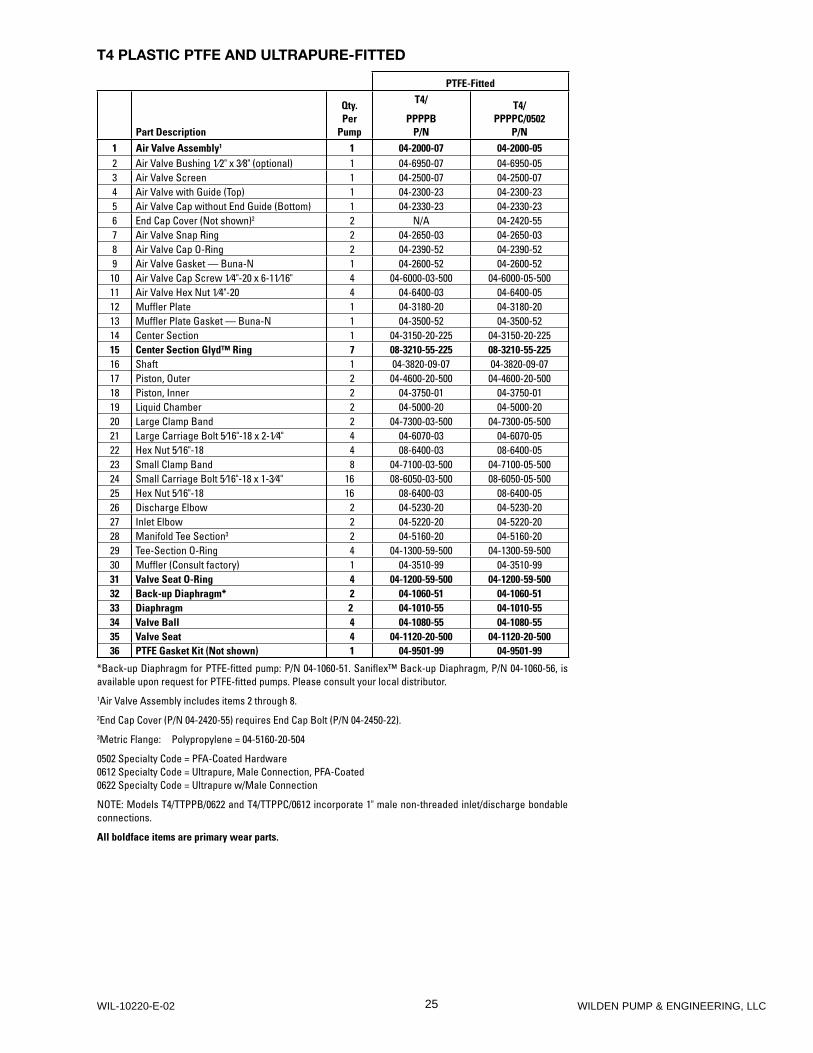
T4 PLASTIC PTFE AND ULTRAPURE-FITTED
PTFE-Fitted
Part Description
Qty. Per
Pump
T4/
PPPPBP/N
T4/PPPPC/0502
P/N1 Air Valve Assembly1 1 04-2000-07 04-2000-052 Air Valve Bushing 1⁄2" x 3⁄8" (optional) 1 04-6950-07 04-6950-053 Air Valve Screen 1 04-2500-07 04-2500-074 Air Valve with Guide (Top) 1 04-2300-23 04-2300-235 Air Valve Cap without End Guide (Bottom) 1 04-2330-23 04-2330-236 End Cap Cover (Not shown)2 2 N/A 04-2420-557 Air Valve Snap Ring 2 04-2650-03 04-2650-038 Air Valve Cap O-Ring 2 04-2390-52 04-2390-529 Air Valve Gasket — Buna-N 1 04-2600-52 04-2600-52
10 Air Valve Cap Screw 1⁄4"-20 x 6-11⁄16" 4 04-6000-03-500 04-6000-05-50011 Air Valve Hex Nut 1⁄4"-20 4 04-6400-03 04-6400-0512 Muffler Plate 1 04-3180-20 04-3180-2013 Muffler Plate Gasket — Buna-N 1 04-3500-52 04-3500-5214 Center Section 1 04-3150-20-225 04-3150-20-22515 Center Section Glyd™ Ring 7 08-3210-55-225 08-3210-55-22516 Shaft 1 04-3820-09-07 04-3820-09-0717 Piston, Outer 2 04-4600-20-500 04-4600-20-50018 Piston, Inner 2 04-3750-01 04-3750-0119 Liquid Chamber 2 04-5000-20 04-5000-2020 Large Clamp Band 2 04-7300-03-500 04-7300-05-50021 Large Carriage Bolt 5⁄16"-18 x 2-1⁄4" 4 04-6070-03 04-6070-0522 Hex Nut 5⁄16"-18 4 08-6400-03 08-6400-0523 Small Clamp Band 8 04-7100-03-500 04-7100-05-50024 Small Carriage Bolt 5⁄16"-18 x 1-3⁄4" 16 08-6050-03-500 08-6050-05-50025 Hex Nut 5⁄16"-18 16 08-6400-03 08-6400-0526 Discharge Elbow 2 04-5230-20 04-5230-2027 Inlet Elbow 2 04-5220-20 04-5220-2028 Manifold Tee Section3 2 04-5160-20 04-5160-2029 Tee-Section O-Ring 4 04-1300-59-500 04-1300-59-50030 Muffler (Consult factory) 1 04-3510-99 04-3510-9931 Valve Seat O-Ring 4 04-1200-59-500 04-1200-59-50032 Back-up Diaphragm* 2 04-1060-51 04-1060-5133 Diaphragm 2 04-1010-55 04-1010-5534 Valve Ball 4 04-1080-55 04-1080-5535 Valve Seat 4 04-1120-20-500 04-1120-20-50036 PTFE Gasket Kit (Not shown) 1 04-9501-99 04-9501-99
*Back-up Diaphragm for PTFE-fi tted pump: P/N 04-1060-51. Sanifl ex™ Back-up Diaphragm, P/N 04-1060-56, is available upon request for PTFE-fi tted pumps. Please consult your local distributor.1Air Valve Assembly includes items 2 through 8.2End Cap Cover (P/N 04-2420-55) requires End Cap Bolt (P/N 04-2450-22).3Metric Flange: Polypropylene = 04-5160-20-504
0502 Specialty Code = PFA-Coated Hardware0612 Specialty Code = Ultrapure, Male Connection, PFA-Coated0622 Specialty Code = Ultrapure w/Male Connection
NOTE: Models T4/TTPPB/0622 and T4/TTPPC/0612 incorporate 1" male non-threaded inlet/discharge bondable connections.
All boldface items are primary wear parts.

26WILDEN PUMP & ENGINEERING, LLC WIL-10220-E-02
SECTION 9C
EXPLODED VIEW/PARTS LISTING
A4PLASTICACCU-FLO™

27 WILDEN PUMP & ENGINEERING, LLCWIL-10220-E-02
A4 PLASTIC ACCU-FLO™
Rubber-Fitted PTFE-Fitted
Part Description
Qty. Per
Pump
A4/PPPPA/0150
P/N
A4/KKPPA/0150
P/N
A4/PPPPA/0150
P/N
A4/KKPPA/0150
P/N
1 Solenoid Valve Assembly 1 04-2000-99-150 04-2000-99-150 04-2000-99-150 04-2000-99-1502 Main Valve Body 1 04-2000-01-150 04-2000-01-150 04-2000-01-150 04-2000-01-1503 Coil 1 00-2110-99-150 00-2110-99-150 00-2110-99-150 00-2110-99-1504 Terminal Connector 1 00-2130-99 00-2130-99 00-2130-99 00-2130-995 Air Valve Gasket — Buna-N 1 04-2600-52 04-2600-52 04-2600-52 04-2600-526 Air Valve Screw 4 04-6000-08 04-6000-08 04-6000-08 04-6000-087 Air Valve Hex Nut 1⁄4"-20 4 04-6400-03 04-6400-03 04-6400-03 04-6400-038 Muffler Plate 1 04-3180-20 04-3180-20 04-3180-20 04-3180-209 Muffler Plate Gasket — Buna-N 1 04-3500-52 04-3500-52 04-3500-52 04-3500-52
10 Center Section 1 04-3150-20-225 04-3150-20-225 04-3150-20-225 04-3150-20-22511 Center Section Glyd™ Ring 7 08-3210-55-255 08-3210-55-255 08-3210-55-255 08-3210-55-25512 Shaft, Rubber/TPE 1 08-3840-09 08-3840-09 N/A N/A
Shaft, PTFE 1 N/A N/A 04-3825-09 04-3825-0913 Shaft, Ultra-Flex™ 1 04-3835-09 04-3835-09 N/A N/A14 Piston, Outer 2 04-4550-20-500 04-4550-21-500 04-4600-21-500 04-4600-21-50015 Piston, Outer, Ultra-Flex™ 2 04-4560-21 04-4560-21 N/A N/A16 Piston, Inner 2 04-3700-08 04-3700-08 04-3750-01 04-3750-0117 Piston, Inner, Ultra-Flex™ 2 04-3760-01-700 04-3760-01-700 N/A N/A18 Liquid Chamber 2 04-5000-20 04-5000-21 04-5000-20 04-5000-2119 Large Clamp Band 2 04-7300-03-500 04-7300-03-500 04-7300-03-500 04-7300-03-50020 Large Carriage Bolt 5⁄16"-18 x 2-1⁄4" 4 04-6070-03 04-6070-03 04-6070-03 04-6070-0321 Hex Nut 5⁄16"-18 4 08-6400-03 08-6400-03 08-6400-03 08-6400-0322 Small Clamp Band 8 04-7100-03-500 04-7100-03-500 04-7100-03-500 04-7100-03-50023 Small Carriage Bolt 5⁄16"-18 x 1-3⁄4" 16 08-6050-03-500 08-6050-03-500 08-6050-03-500 08-6050-03-50024 Hex Nut 5⁄16"-18 16 08-6400-03 08-6400-03 08-6400-03 08-6400-0325 Discharge Elbow 2 04-5230-20 04-5230-21 04-5230-20 04-5230-2126 Inlet Elbow 2 04-5220-20 04-5220-21 04-5220-20 04-5220-2127 Manifold Tee Section3 2 04-5160-20 04-5160-21 04-5160-20 04-5160-2128 Tee-Section O-Ring 4 * * 04-1300-60-500 04-1300-60-50029 Muffler (Consult factory) 1 04-3510-99 04-3510-99 04-3510-99 04-3510-9930 Valve Seat O-Ring 4 * * 04-1200-60-500 04-1200-60-50031 Diaphragm 2 * * 04-1010-55 04-1010-5532 Valve Ball 4 * * 04-1080-55 04-1080-5533 Valve Seat 4 04-1120-20-500 04-1120-21-500 04-1120-20-500 04-1120-21-50034 PTFE Gasket Kit (Not shown) 1 N/R N/R 04-9501-99 04-9501-9935 Bumper Pad 2 08-6900-23-50 08-6900-23-50 08-6900-23-50 08-6900-23-5036 Spacer, Ultra-Flex™ 2 04-3860-08 04-3860-08 04-3860-08 04-3860-08
1Solenoid Valve Assembly includes items 2 through 4.3Metric Flange: Polypropylene = 04-5160-20/0504 PVDF = 04-5160-21/0504
NOTE: Additional solenoid options are available. Please consult Section 10B for further information.
0150 Specialty Code = Solenoid Operated, 24V DC
All boldface items are primary wear parts.
28WILDEN PUMP & ENGINEERING, LLC WIL-10220-E-02
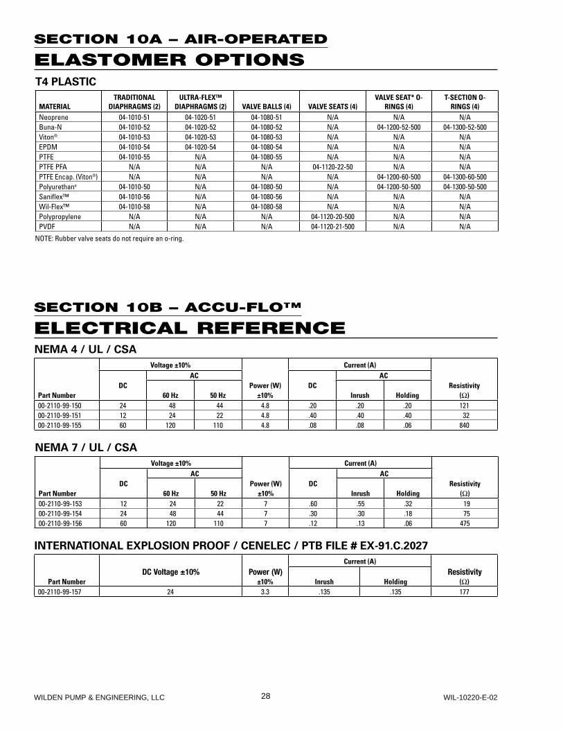
SECTION 10A – AIR-OPERATED
ELASTOMER OPTIONS
SECTION 10B – ACCU-FLO™
ELECTRICAL REFERENCE
T4 PLASTIC
MATERIALTRADITIONAL
DIAPHRAGMS (2)ULTRA-FLEX™
DIAPHRAGMS (2) VALVE BALLS (4) VALVE SEATS (4)VALVE SEAT* O-
RINGS (4)T-SECTION O-
RINGS (4)Neoprene 04-1010-51 04-1020-51 04-1080-51 N/A N/A N/ABuna-N 04-1010-52 04-1020-52 04-1080-52 N/A 04-1200-52-500 04-1300-52-500Viton® 04-1010-53 04-1020-53 04-1080-53 N/A N/A N/AEPDM 04-1010-54 04-1020-54 04-1080-54 N/A N/A N/APTFE 04-1010-55 N/A 04-1080-55 N/A N/A N/APTFE PFA N/A N/A N/A 04-1120-22-50 N/A N/APTFE Encap. (Viton®) N/A N/A N/A N/A 04-1200-60-500 04-1300-60-500Polyurethane 04-1010-50 N/A 04-1080-50 N/A 04-1200-50-500 04-1300-50-500Sanifl ex™ 04-1010-56 N/A 04-1080-56 N/A N/A N/AWil-Flex™ 04-1010-58 N/A 04-1080-58 N/A N/A N/APolypropylene N/A N/A N/A 04-1120-20-500 N/A N/APVDF N/A N/A N/A 04-1120-21-500 N/A N/A
NOTE: Rubber valve seats do not require an o-ring.
NEMA 4 / UL / CSA
Voltage ±10% Current (A)AC AC
DC Power (W) DC ResistivityPart Number 60 Hz 50 Hz ±10% Inrush Holding (Ω)00-2110-99-150 24 48 44 4.8 .20 .20 .20 12100-2110-99-151 12 24 22 4.8 .40 .40 .40 3200-2110-99-155 60 120 110 4.8 .08 .08 .06 840
NEMA 7 / UL / CSA
Voltage ±10% Current (A)AC AC
DC Power (W) DC ResistivityPart Number 60 Hz 50 Hz ±10% Inrush Holding (Ω)00-2110-99-153 12 24 22 7 .60 .55 .32 1900-2110-99-154 24 48 44 7 .30 .30 .18 7500-2110-99-156 60 120 110 7 .12 .13 .06 475
INTERNATIONAL EXPLOSION PROOF / CENELEC / PTB FILE # EX-91.C.2027
Current (A)DC Voltage ±10% Power (W) Resistivity
Part Number ±10% Inrush Holding (Ω)00-2110-99-157 24 3.3 .135 .135 177

Item # Serial #
Company Where Purchased
Company Name
Industry
Name Title
Street Address
City State Postal Code Country
Telephone Fax E-mail Web Address
Number of pumps in facility? Number of Wilden pumps?
Types of pumps in facility (check all that apply): Diaphragm Centrifugal Gear Submersible Lobe
Other
Media being pumped?
How did you hear of Wilden Pump? Trade Journal Trade Show Internet/E-mail Distributor
Other
P U M P I N F O R M AT I O N
PLEASE PRINT OR TYPE AND FAX TO WILDEN
YO U R I N F O R M AT I O N
ONCE COMPLETE, FAX TO (909) 783-3440
NOTE: WARRANTY VOID IF PAGE IS NOT FAXED TO WILDEN
WILDEN PUMP & ENGINEERING, LLC
W A R R A N T YEach and every product manufactured by Wilden Pump and Engineering, LLC is built to meet the highest standards of quality. Every pump is functionally tested to insure integrity of operation.
Wilden Pump and Engineering, LLC warrants that pumps, accessories and parts manufactured or supplied by it to be free from defects in material and workmanship for a period of five (5) years from date of installation or six (6) years from date of manufacture, whichever comes first. Failure due to normal wear, misapplication, or abuse is, of course, excluded from this warranty.
Since the use of Wilden pumps and parts is beyond our control, we cannot guarantee the suitability of any pump or part for a particular application and Wilden Pump and Engineering, LLC shall not be liable for any consequential damage or expense arising from the use or misuse of its products on any application. Responsibility is limited solely to replacement or repair of defective Wilden pumps and parts.
All decisions as to the cause of failure are the sole determination of Wilden Pump and Engineering, LLC.
Prior approval must be obtained from Wilden for return of any items for warranty consideration and must be accompanied by the appropriate MSDS for the product(s) involved. A Return Goods Tag, obtained from an authorized Wilden distributor, must be included with the items which must be shipped freight prepaid.
The foregoing warranty is exclusive and in lieu of all other warranties expressed or implied (whether written or oral) including all implied warranties of merchantability and fitness for any particular purpose. No distributor or other person is authorized to assume any liability or obligation for Wilden Pump and Engineering, LLC other than expressly provided herein.