T4/A4 EOM - Genemco · t4/a4 wil-10260-e-02 replaces eom t4 & a4m 4/05. table of contents page #...
35
EOM Simplify your process Engineering Operation & Maintenance Original ™ Series METAL Pumps T4/A4 WIL-10260-E-02 REPLACES EOM T4 & A4M 4/05
Transcript of T4/A4 EOM - Genemco · t4/a4 wil-10260-e-02 replaces eom t4 & a4m 4/05. table of contents page #...
EOM
S i m p l i f y y o u r p r o c e s s
E n g i n e e r i n g O p e r a t i o n &M a i n t e n a n c eOriginal™ Series METAL Pumps
T4/A4
WIL-10260-E-02REPLACES EOM T4 & A4M 4/05
TABLE OF CONTENTSPAGE #
SECTION 1 — CAUTIONS ............................................................................................ 1
SECTION 2 — PUMP DESIGNATION SYSTEM ......................................... 2
SECTION 3 — HOW IT WORKS (PUMP & AIR SYSTEMS) ............ 3
SECTION 4 — DIMENSIONAL DRAWINGS A. T4 METAL Air-Operated ..................................................................................................... 4 B. A4 METAL Accu-Flo™ ....................................................................................................... 4 C. T4 METAL SANIFLOFDA Air-Operated ................................................................................. 5 D. T4 METAL Stallion .............................................................................................................. 5
SECTION 5 — PERFORMANCE CURVES A. T4 METAL Rubber-Fitted ................................................................................................... 6 B. T4 METAL Ultra-Flex™-Fitted ............................................................................................ 6 C. T4 METAL TPE-Fitted ........................................................................................................ 7 D. T4 METAL PTFE-Fitted ...................................................................................................... 7 E. T4 METAL Stallion Ultra-Flex™-Fitted ............................................................................... 8 F. A4 METAL Accu-Flo™ Rubber/TPE-Fitted ........................................................................ 9 G. A4 METAL Accu-Flo™ Rubber/TPE 70/30 Operating Condition ...................................... 9 H. A4 METAL Accu-Flo™ Ultra-Flex™/PTFE-Fitted .............................................................. 10 I. A4 METAL Accu-Flo™ Ultra-Flex™/PTFE-Fitted 70/30 Operating Condition .................. 10
SECTION 6 — SUCTION LIFT CURVES & DATA A. T4 METAL Air-Controlled ................................................................................................... 11 B. A4 METAL Accu-Flo™ ....................................................................................................... 11
SECTION 7 — INSTALLATION & OPERATION A. Installation — Turbo-Flo™ Suggested Installation Drawing .............................................. 12 B. Operating and Maintenance .............................................................................................. 13 C. Principles Behind Accu-Flo™ Pumps................................................................................ 14 D. Installation — Accu-Flo™ .................................................................................................. 14 E. Suggested Operation and Maintenance ............................................................................ 15 F. Troubleshooting — Turbo-Flo™ ......................................................................................... 16 G. Troubleshooting — Accu-Flo™ .......................................................................................... 16
SECTION 8 — DIRECTIONS FOR DISASSEMBLY/REASSEMBLY A. T4 METAL Wetted Path — Tools Required, Torque Specs, Cautions ............................... 17 B. Turbo-Flo™ Air Valve/Center Block – Disassembly, Cleaning, Inspection ........................ 20 C. Reassembly Hints & Tips ................................................................................................... 22 D. PTFE Gasket Kit Installation .............................................................................................. 23
SECTION 9 — EXPLODED VIEW/PARTS LISTING A. T4 METAL Rubber/TPE-Fitted ........................................................................................... 24 B. T4 METAL PTFE-Fitted ...................................................................................................... 26 C. A4 METAL Accu-Flo™ ....................................................................................................... 28
SECTION 10 — REFERENCE A. Air-Operated Elastomer Options ........................................................................................ 30 B. Stallion Elastomer Options ................................................................................................ 30 C. Accu-Flo™ Electrical Reference ........................................................................................ 31
Cla
ss
I &II Ozone
Depleting Substanc
esNON
USEU.S. Clean Air Act
Amendments of 1990
1 WILDEN PUMP & ENGINEERING, LLCWIL-10260-E-02
SECTION 1
MODEL T4 METALCAUTIONS – READ FIRST!
TEMPERATURE LIMITS: Polypropylene 0°C to 79°C 32°F to 175°F PVDF –12°C to 107°C 10°F to 225°F Neoprene –17.8°C to 93.3°C 0°F to 200°F Buna-N –12.2°C to 82.2°C 10°F to 180°F EPDM –51.1°C to 137.8°C –60°F to 280°F Viton® –40°C to 176.7°C –40°F to 350°F Wil-Flex™ –40°C to 107.2°C –40°F to 225°F Polyurethane 12.2°C to 65.6°C 10°F to 150°F Saniflex™ –28.9°C to 104.4°C –20°F to 220°F PTFE 4.4°C to 104.4°C 40°F to 220°F
CAUTION: When choosing pump materials, be sure to check the temperature limits for all wetted compo-nents. Example: Viton® has a maximum limit of 176.7°C (350°F) but polypropylene has a maximum limit of only 79°C (175°F).
CAUTION: Maximum temperature limits are based upon mechanical stress only. Certain chemicals will significantly reduce maximum safe operating tempera-tures. Consult engineering guide for chemical compat-ibility and temperature limits.
CAUTION: Always wear safety glasses when operat-ing pump. If diaphragm rupture occurs, material being pumped may be forced out air exhaust.
WARNING: Prevention of static sparking — If static sparking occurs, fire or explosion could result. Pump, valves, and containers must be properly grounded when handling flammable fluids and whenever discharge of static electricity is a hazard.
CAUTION: Do not exceed 8.6 bar (125 psig) air supply pressure.
CAUTION: Before any maintenance or repair is attempted, the compressed air line to the pump should be disconnected and all air pressure allowed to bleed from pump. Disconnect all intake, discharge and air lines. Drain the pump by turning it upside down and allowing any fluid to flow into a suitable container.
CAUTION: Blow out air line for 10 to 20 seconds before attaching to pump to make sure all pipe line debris is clear. Use an in-line air filter. A 5µ (micron) air filter is recommended.
NOTE: When installing PTFE diaphragms, it is impor-tant to tighten outer pistons simultaneously (turning in opposite directions) to ensure tight fit.
NOTE: Tighten clamp bands and retainers prior to instal-lation. Fittings may loosen during transportation.
NOTE: Before starting disassembly, mark a line from each liquid chamber to its corresponding air chamber. This line will assist in proper alignment during reas-sembly.
CAUTION: Verify the chemical compatibility of the process and cleaning fluid to the pump’s component materials in the Chemical Resistance Guide (see E4).
CAUTION: When removing the end cap using compressed air, the air valve end cap may come out with considerable force. Hand protection such as a padded glove or rag should be used to capture the end cap.
CAUTION: Only explosion proof (NEMA 7) solenoid valves should be used in areas where explosion proof equipment is required.
NOTE: All non lube-free air-operated pumps must be lubricated. Wilden suggests an arctic 5 weight oil (ISO grade 15). Do not over-lubricate pump. Over-lubrica-tion will reduce pump performance.
NOTE: On cast iron pumps equipped with PTFE diaphragms, balls and sealing rings, PTFE gasket kits should be utilized.
NOTE: UL-listed pumps must not exceed 3.4 bar (50 psig) air supply pressure.
2WILDEN PUMP & ENGINEERING, LLC WIL-10260-E-02
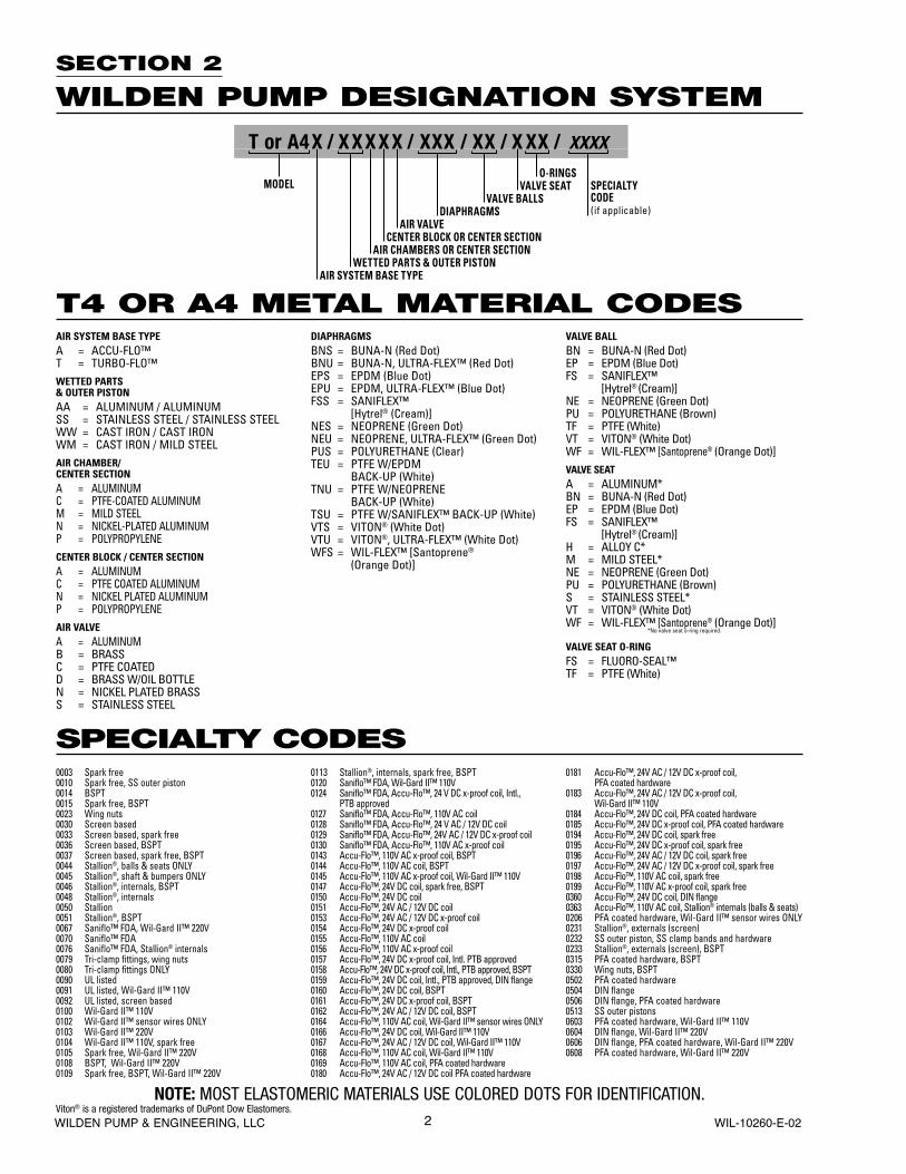
SECTION 2
WILDEN PUMP DESIGNATION SYSTEM
NOTE: MOST ELASTOMERIC MATERIALS USE COLORED DOTS FOR IDENTIFICATION.Viton® is a registered trademarks of DuPont Dow Elastomers.
T4 OR A4 METAL MATERIAL CODES
SPECIALTY CODES
AIR SYSTEM BASE TYPEA = ACCU-FLO™T = TURBO-FLO™WETTED PARTS & OUTER PISTONAA = ALUMINUM / ALUMINUMSS = STAINLESS STEEL / STAINLESS STEELWW = CAST IRON / CAST IRONWM = CAST IRON / MILD STEELAIR CHAMBER/CENTER SECTIONA = ALUMINUMC = PTFE-COATED ALUMINUMM = MILD STEELN = NICKEL-PLATED ALUMINUMP = POLYPROPYLENECENTER BLOCK / CENTER SECTIONA = ALUMINUMC = PTFE COATED ALUMINUMN = NICKEL PLATED ALUMINUMP = POLYPROPYLENEAIR VALVEA = ALUMINUMB = BRASSC = PTFE COATEDD = BRASS W/OIL BOTTLEN = NICKEL PLATED BRASSS = STAINLESS STEEL
DIAPHRAGMSBNS = BUNA-N (Red Dot)BNU = BUNA-N, ULTRA-FLEX™ (Red Dot)EPS = EPDM (Blue Dot)EPU = EPDM, ULTRA-FLEX™ (Blue Dot)FSS = SANIFLEX™
[Hytrel® (Cream)]NES = NEOPRENE (Green Dot)NEU = NEOPRENE, ULTRA-FLEX™ (Green Dot)PUS = POLYURETHANE (Clear)TEU = PTFE W/EPDM BACK-UP (White)TNU = PTFE W/NEOPRENE BACK-UP (White)TSU = PTFE W/SANIFLEX™ BACK-UP (White)VTS = VITON® (White Dot)VTU = VITON®, ULTRA-FLEX™ (White Dot)WFS = WIL-FLEX™ [Santoprene®
(Orange Dot)]
VALVE BALLBN = BUNA-N (Red Dot)EP = EPDM (Blue Dot)FS = SANIFLEX™
[Hytrel® (Cream)]NE = NEOPRENE (Green Dot)PU = POLYURETHANE (Brown)TF = PTFE (White)VT = VITON® (White Dot)WF = WIL-FLEX™ [Santoprene® (Orange Dot)]VALVE SEATA = ALUMINUM*BN = BUNA-N (Red Dot)EP = EPDM (Blue Dot)FS = SANIFLEX™
[Hytrel® (Cream)]H = ALLOY C*M = MILD STEEL*NE = NEOPRENE (Green Dot)PU = POLYURETHANE (Brown)S = STAINLESS STEEL*VT = VITON® (White Dot)WF = WIL-FLEX™ [Santoprene® (Orange Dot)]
*No valve seat o-ring required.
VALVE SEAT O-RINGFS = FLUORO-SEAL™TF = PTFE (White)
0003 Spark free0010 Spark free, SS outer piston0014 BSPT0015 Spark free, BSPT0023 Wing nuts0030 Screen based0033 Screen based, spark free0036 Screen based, BSPT0037 Screen based, spark free, BSPT0044 Stallion®, balls & seats ONLY0045 Stallion®, shaft & bumpers ONLY0046 Stallion®, internals, BSPT0048 Stallion®, internals0050 Stallion0051 Stallion®, BSPT0067 Saniflo™ FDA, Wil-Gard II™ 220V0070 Saniflo™ FDA0076 Saniflo™ FDA, Stallion® internals0079 Tri-clamp fittings, wing nuts0080 Tri-clamp fittings ONLY0090 UL listed0091 UL listed, Wil-Gard II™ 110V0092 UL listed, screen based0100 Wil-Gard II™ 110V0102 Wil-Gard II™ sensor wires ONLY0103 Wil-Gard II™ 220V0104 Wil-Gard II™ 110V, spark free0105 Spark free, Wil-Gard II™ 220V0108 BSPT, Wil-Gard II™ 220V0109 Spark free, BSPT, Wil-Gard II™ 220V
0113 Stallion®, internals, spark free, BSPT0120 Saniflo™ FDA, Wil-Gard II™ 110V0124 Saniflo™ FDA, Accu-Flo™, 24 V DC x-proof coil, Intl.,
PTB approved0127 Saniflo™ FDA, Accu-Flo™, 110V AC coil0128 Saniflo™ FDA, Accu-Flo™, 24 V AC / 12V DC coil0129 Saniflo™ FDA, Accu-Flo™, 24V AC / 12V DC x-proof coil0130 Saniflo™ FDA, Accu-Flo™, 110V AC x-proof coil0143 Accu-Flo™, 110V AC x-proof coil, BSPT0144 Accu-Flo™, 110V AC coil, BSPT0145 Accu-Flo™, 110V AC x-proof coil, Wil-Gard II™ 110V0147 Accu-Flo™, 24V DC coil, spark free, BSPT0150 Accu-Flo™, 24V DC coil0151 Accu-Flo™, 24V AC / 12V DC coil0153 Accu-Flo™, 24V AC / 12V DC x-proof coil0154 Accu-Flo™, 24V DC x-proof coil0155 Accu-Flo™, 110V AC coil0156 Accu-Flo™, 110V AC x-proof coil0157 Accu-Flo™, 24V DC x-proof coil, Intl. PTB approved0158 Accu-Flo™, 24V DC x-proof coil, Intl., PTB approved, BSPT0159 Accu-Flo™, 24V DC coil, Intl., PTB approved, DIN flange0160 Accu-Flo™, 24V DC coil, BSPT0161 Accu-Flo™, 24V DC x-proof coil, BSPT0162 Accu-Flo™, 24V AC / 12V DC coil, BSPT0164 Accu-Flo™, 110V AC coil, Wil-Gard II™ sensor wires ONLY0166 Accu-Flo™, 24V DC coil, Wil-Gard II™ 110V0167 Accu-Flo™, 24V AC / 12V DC coil, Wil-Gard II™ 110V0168 Accu-Flo™, 110V AC coil, Wil-Gard II™ 110V0169 Accu-Flo™, 110V AC coil, PFA coated hardware0180 Accu-Flo™, 24V AC / 12V DC coil PFA coated hardware
0181 Accu-Flo™, 24V AC / 12V DC x-proof coil, PFA coated hardware
0183 Accu-Flo™, 24V AC / 12V DC x-proof coil, Wil-Gard II™ 110V
0184 Accu-Flo™, 24V DC coil, PFA coated hardware0185 Accu-Flo™, 24V DC x-proof coil, PFA coated hardware0194 Accu-Flo™, 24V DC coil, spark free0195 Accu-Flo™, 24V DC x-proof coil, spark free0196 Accu-Flo™, 24V AC / 12V DC coil, spark free0197 Accu-Flo™, 24V AC / 12V DC x-proof coil, spark free0198 Accu-Flo™, 110V AC coil, spark free0199 Accu-Flo™, 110V AC x-proof coil, spark free0360 Accu-Flo™, 24V DC coil, DIN flange0363 Accu-Flo™, 110V AC coil, Stallion® internals (balls & seats)0206 PFA coated hardware, Wil-Gard II™ sensor wires ONLY0231 Stallion®, externals (screen)0232 SS outer piston, SS clamp bands and hardware0233 Stallion®, externals (screen), BSPT0315 PFA coated hardware, BSPT0330 Wing nuts, BSPT0502 PFA coated hardware0504 DIN flange0506 DIN flange, PFA coated hardware0513 SS outer pistons0603 PFA coated hardware, Wil-Gard II™ 110V0604 DIN flange, Wil-Gard II™ 220V0606 DIN flange, PFA coated hardware, Wil-Gard II™ 220V0608 PFA coated hardware, Wil-Gard II™ 220V
T or A4X / XXXXX / XXX / XX / X XX / XXXX
O-RINGSMODEL VALVE SEAT
VALVE BALLSDIAPHRAGMS
AIR VALVECENTER BLOCK OR CENTER SECTION
AIR CHAMBERS OR CENTER SECTIONWETTED PARTS & OUTER PISTON
AIR SYSTEM BASE TYPE
SPECIALTYCODE(if applicable)
3 WILDEN PUMP & ENGINEERING, LLCWIL-10260-E-02
SECTION 3
THE WILDEN PUMP — HOW IT WORKSThe Wilden diaphragm pump is an air-operated, positive displacement, self-priming pump. These drawings show the flow pattern through the pump upon its initial stroke. It is assumed the pump has no fluid in it prior to its initial stroke.
FIGURE 1 The air valve directs pres-surized air to the back side of diaphragm A. The compressed air is applied directly to the liquid column separated by elas-tomeric diaphragms. The diaphragm acts as a separation membrane between the compressed air and liquid, balanc-ing the load and removing mechani-cal stress from the diaphragm. The compressed air moves the diaphragm away from the center block of the pump. The opposite diaphragm is pulled in by the shaft connected to the pressur-ized diaphragm. Diaphragm B is on its suction stroke; air behind the diaphragm has been forced out to the atmosphere through the exhaust port of the pump. The movement of diaphragm B toward the center block of the pump creates a vacuum within chamber B. Atmospheric pressure forces fluid into the inlet mani-fold forcing the inlet valve ball off its seat. Liquid is free to move past the inlet valve ball and fill the liquid chamber (see shaded area).
FIGURE 2 When the pressurized diaphragm, diaphragm A, reaches the limit of its discharge stroke, the air valve redirects pressurized air to the back side of diaphragm B. The pressurized air forces diaphragm B away from the center block while pulling diaphragm A to the center block. Diaphragm B is now on its discharge stroke. Diaphragm B forces the inlet valve ball onto its seat due to the hydraulic forces developed in the liquid chamber and manifold of the pump. These same hydraulic forces lift the discharge valve ball off its seat, while the opposite discharge valve ball is forced onto its seat, forcing fluid to flow through the pump discharge. The move-ment of diaphragm A toward the center block of the pump creates a vacuum within liquid chamber A. Atmospheric pressure forces fluid into the inlet mani-fold of the pump. The inlet valve ball is forced off its seat allowing the fluid being pumped to fill the liquid chamber.
FIGURE 3 At completion of the stroke, the air valve again redirects air to the back side of diaphragm A, which starts diaphragm B on its exhaust stroke. As the pump reaches its original starting point, each diaphragm has gone through one exhaust and one discharge stroke. This constitutes one complete pump-ing cycle. The pump may take several cycles to completely prime depending on the conditions of the application.
RIGHT STROKE MID STROKE LEFT STROKE
4WILDEN PUMP & ENGINEERING, LLC WIL-10260-E-02
SECTION 4A
DIMENSIONAL DRAWINGT4 METAL
SECTION 4B
DIMENSIONAL DRAWINGA4 METAL ACCU-FLO™
38 mm (1-1/2") BSP/ FNPT LIQUID INLET
32 mm (1-1/4") BSP/FNPT LIQUID DISCHARGE
13 mm (1/2") BSP/FNPT AIR INLET
13 mm (1/2") BSP/FNPT AIR INLET
A
B
C
D
EF
GH
JK
L
M
NP
RS
T
U
38 mm (1-1/2") BSP/FNPT LIQUID INLET
32 mm (1-1/4") BSP/FNPT LIQUID DISCHARGE
19 mm (3/4") BSP/ FNPT AIR EXHAUST
A
B
C
D
E
FG
HJ
K
L
MN
PR
S
T
DIMENSIONS
ITEM METRIC (mm) STANDARD (inch)
A 391 15.4B 63 2.5C 219 8.6D 442 17.4E 285 11.2F 262 10.3G 224 8.8H 152 6.0J 178 7.0K 67 2.6L 11 0.4
BSP threads available.
DIMENSIONS
ITEM METRIC (mm) STANDARD (inch)
A 391 15.4B 63 2.5C 198 7.8D 442 17.4E 95 3.8F 285 11.2G 262 10.3H 224 8.8J 152 6.0K 178 7.0L 51 2.0M 11 0.4N 336 13.2P 222 8.8R 151 5.9S 195 7.7T 49 1.9U 13 0.5
BSP threads available.
5 WILDEN PUMP & ENGINEERING, LLCWIL-10260-E-02
SECTION 4C
DIMENSIONAL DRAWINGT4 METAL SANIFLOFDA
SECTION 4D
DIMENSIONAL DRAWINGT4 METAL STALLION
Accu-Flo™ model available.
38 mm (1-1/2") BSP/FNPT LIQUID INLET
32 mm (1-1/4") BSP/FNPT LIQUID DISCHARGE
13 mm (1/2") BSP/FNPT AIR INLET
A
FG
H
J
B
C
D
E
51 mm (2") TRI-CLAMP
51 mm (2") TRI-CLAMP
13 mm (1/2") BSP/FNPT AIR INLET
19 mm (3/4") BSP/FNPT AIR EXHAUST
A
FG
HJ
K
L
B
C
D
E
DIMENSIONS
ITEM METRIC (mm) STANDARD (inch)
A 391 15.4B 63 2.5C 219 8.6D 442 17.4E 285 11.2F 262 10.3G 224 8.8H 152 6.0J 178 7.0K 67 2.6L 11 0.4
DIMENSIONS
ITEM METRIC (mm) STANDARD (inch)
A 391 15.4B 77 3.0C 232 9.1D 449 17.7E 285 11.2F 48 1.9G 197 7.8H 121 4.8J Ø14 Ø 0.6
BSP threads available.
6WILDEN PUMP & ENGINEERING, LLC WIL-10260-E-02
SECTION 5A
PERFORMANCE CURVEST4 METAL RUBBER-FITTEDHeight .................................. 442 mm (17.4")Width ................................... 391 mm (15.4")Depth .................................. 285 mm (11.2")Est. Ship Weight ..........Aluminum 17 kg (38 lbs)
Stainless Steel 26 kg (57 lbs)Cast Iron 26 kg (57 lbs)
Air Inlet ....................................13 mm (1/2")Inlet ..................................... 38 mm (1-1/2")Outlet .................................. 32 mm (1-1/4")Suction Lift ................................5.49 m (18')
8.53 m (28')Displacement per Stroke ......................... 1.02 l (0.27 gal.)1
Max. Flow Rate ................. 288 lpm (76 gpm)Max. Size Solids ...................4.8 mm (3/16")1Displacement per stroke was calculated at 4.8 bar (70 psig) air inlet pressure against a 2 bar (30 psig) head pressure.
Example: To pump 113.6 lpm (30 gpm) against a discharge pressure head of 2.7 bar (40 psig) requires 4.1 bar (60 psig) and 25.5 Nm3/h (15 scfm) air consumption. (See dot on chart.)
Caution: Do not exceed 8.6 bar (125 psig) air supply pressure.
Flow rates indicated on chart were determined by pumping water.
For optimum life and performance, pumps should be specified so that daily operation parameters will fall in the center of the pump performance curve.
[LPM]Water Discharge Flow Rates
SECTION 5B
PERFORMANCE CURVEST4 METAL ULTRA-FLEX™-FITTEDHeight .................................. 452 mm (17.4")Width ................................... 391 mm (15.4")Depth .................................. 285 mm (11.2")Est. Ship Weight ..........Aluminum 17 kg (38 lbs)
Stainless Steel 26 kg (57 lbs)Cast Iron 26 kg (57 lbs)
Air Inlet ....................................13 mm (1/2")Inlet ..................................... 38 mm (1-1/2")Outlet .................................. 32 mm (1-1/4")Suction Lift ......................... 4.88 m Dry (16')
8.23 m Wet (27')Displacement per Stroke ........................... 0.68 l (0.18 gal.)1
Max. Flow Rate ................ 235 lpm (62 gpm) Max. Size Solids ...................4.8 mm (3/16") 1Displacement per stroke was calculated at 4.8 bar (70 psig) air inlet pressure against a 2 bar (30 psig) head pressure.
Example: To pump 94.6 lpm (25 gpm) against a discharge pressure head of 2.7 bar (40 psig) requires 4 bar (60 psig) and 34 Nm3/h (20 scfm) air consumption. (See dot on chart.)
Caution: Do not exceed 8.6 bar (125 psig) air supply pressure.
Flow rates indicated on chart were determined by pumping water.
For optimum life and performance, pumps should be specified so that daily operation parameters will fall in the center of the pump performance curve.
[LPM]
Water Discharge Flow Rates
7 WILDEN PUMP & ENGINEERING, LLCWIL-10260-E-02
SECTION 5C
PERFORMANCE CURVEST4 METAL TPE-FITTEDHeight .................................. 442 mm (17.4")Width ................................... 391 mm (15.4")Depth .................................. 285 mm (11.2")Est. Ship Weight ..........Aluminum 17 kg (38 lbs)
Stainless Steel 26 kg (57 lbs)Cast Iron 26 kg (57 lbs)
Air Inlet ....................................13 mm (1/2")Inlet ..................................... 38 mm (1-1/2")Outlet .................................. 32 mm (1-1/4")Suction Lift ......................... 4.27 m Dry (14')
8.23 m Wet (27')Displacement per Stroke ......................... 1.17 l (0.31 gal.)1
Max. Flow Rate ................. 307 lpm (81 gpm)Max. Size Solids ...................4.8 mm (3/16")1Displacement per stroke was calculated at 70 psig (4.8 bar) air inlet pressure against a 2 bar (30 psig) head pressure.
Example: To pump 113.6 lpm (30 gpm) against a discharge pressure head of 2.7 bar (40 psig) requires 4.1 bar (60 psig) and 25.5 Nm3/h (15 scfm) air consumption. (See dot on chart.)
Caution: Do not exceed 8.6 bar (125 psig) air supply pressure.
Flow rates indicated on chart were determined by pumping water.
For optimum life and performance, pumps should be specified so that daily operation parameters will fall in the center of the pump performance curve.
[LPM]Water Discharge Flow Rates
SECTION 5D
PERFORMANCE CURVEST4 METAL PTFE-FITTEDHeight .................................. 442 mm (17.4")Width ................................... 391 mm (15.4")Depth .................................. 285 mm (11.2")Est. Ship Weight ..........Aluminum 17 kg (38 lbs)
Stainless Steel 26 kg (57 lbs)Cast Iron 26 kg (57 lbs)
Air Inlet ....................................13 mm (1/2")Inlet ..................................... 38 mm (1-1/2")Outlet .................................. 32 mm (1-1/4")Suction Lift ........................... 2.74 m Dry (9')
8.53 m Wet (28')Displacement per Stroke ........................... 0.53 l (0.14 gal.)1
Max. Flow Rate ................. 235 lpm (62 gpm)Max. Size Solids ...................4.8 mm (3/16")1Displacement per stroke was calculated at 4.8 bar (70 psig) air inlet pressure against a 2 bar (30 psig) head pressure.
Example: To pump 94.6 lpm (25 gpm) against a discharge pressure head of 2.7 bar (40 psig) requires 4.1 bar (60 psig) and 51 Nm3/h (30 scfm) air consumption. (See dot on chart.)
Caution: Do not exceed 8.6 bar (125 psig) air supply pressure.
Flow rates indicated on chart were determined by pumping water.
For optimum life and performance, pumps should be specified so that daily operation parameters will fall in the center of the pump performance curve.
[LPM]Water Discharge Flow Rates
8WILDEN PUMP & ENGINEERING, LLC WIL-10260-E-02
SECTION 5E
PERFORMANCE CURVEST4 METAL STALLION ULTRA-FLEX™-FITTEDHeight .................................. 449 mm (17.7")Width ................................... 391 mm (15.4")Depth .................................. 285 mm (11.2")Est. Ship Weight ..........Aluminum 20 kg (44 lbs)Air Inlet ....................................13 mm (1/2")Inlet ..................................... 38 mm (1-1/2")Outlet .................................. 32 mm (1-1/4")Suction Lift ......................... 4.27 m Dry (14')
8.23 m Wet (27')Displacement per Stroke ........................... 0.64 l (0.17 gal.)1
Max. Flow Rate ................. 216 lpm (57 gpm)Max. Size Solids ......................13 mm (1/2")1Displacement per stroke was calculated at 4.8 bar (70 psig) air inlet pressure against a 2 bar (30 psig) head pressure.
Example: To pump 98.4 lpm (26 gpm) against a discharge pressure head of 2.7 bar (40 psig) requires 4.1 bar (60 psig) and 35.7 Nm3/h (21 scfm) air consumption. (See dot on chart.)
Caution: Do not exceed 8.6 bar (125 psig) air supply pressure.
Flow rates indicated on chart were determined by pumping water.
For optimum life and performance, pumps should be specified so that daily operation parameters will fall in the center of the pump performance curve.
[LPM]Water Discharge Flow Rates
9 WILDEN PUMP & ENGINEERING, LLCWIL-10260-E-02
SECTION 5F
PERFORMANCE CURVESA4 METAL ACCU-FLO™ RUBBER-FITTEDHeight .................................. 442 mm (17.4")Width ................................... 391 mm (15.4")Depth .................................. 285 mm (11.2")Est. Ship Weight ..........Aluminum 16 kg (36 lbs)
Stainless Steel 25 kg (55 lbs)Cast Iron 25 kg (55 lbs)Hastelloy 25 kg (55 lbs)
Air Inlet ....................................10 mm (3/8")Inlet ..................................... 38 mm (1-1/2")Outlet .................................. 32 mm (1-1/4")Suction Lift ........................... 7.6 m Dry (25')
8.8 m Wet (29')Displacement per Stroke ........................... 0.53 l (0.14 gal.)1
Max. Flow Rate ................. 174 lpm (46 gpm)Max. Size Solids ...................4.8 mm (3/16")1Displacement per stroke was calculated at 4.8 bar (70 psig) air inlet pressure against a 2 bar (30 psig) head pressure.
Example: To pump 49 lpm (13 gpm) against a discharge pressure head of 2.7 bar (40 psig) requires 4.1 bar (60 psig) and 20 Nm3/h(12scfm) air consumption, and a pump speed of 115 strokes/minute. (See dot on chart.)
Caution: Do not exceed 8.6 bar (125 psig) air supply pressure.
Flow curves are for “optimal speed” conditions only. The “optimal speed” is that speed which provides the maximum flow under a particular air and fluid pressure condition. The optimal speed varies for different fluid and air pressures. Recommendations for optimal speed can be found on the right side of the flow curve.
Flow rates indicated on chart were determined by pumping water.
For optimum life and performance, pumps should be specified so that daily operation parameters will fall in the center of the pump performance curve.
[LPM]
Water Discharge Flow Rates
SECTION 5G
70/30 OPERATING CONDITIONA4 METAL ACCU-FLO™ RUBBER-FITTED
[LPM]Water Discharge Flow Rates
This curve demonstrates the flow created when the stroke rate is modi-fied under a static air and fluid pres-sure condition. This curve can be applied to different pressure conditions to estimate the change in flow due to stroke rate.
10WILDEN PUMP & ENGINEERING, LLC WIL-10260-E-02
SECTION 5I
70/30 OPERATING CONDITIONA4 METAL ACCU-FLO™ ULTRA-FLEX™-FITTED
[LPM]Water Discharge Flow Rates
SECTION 5H
PERFORMANCE CURVESA4 METAL ACCU-FLO™ ULTRA-FLEX™-FITTEDHeight .................................. 442 mm (17.4")Width ................................... 391 mm (15.4")Depth .................................. 285 mm (11.2")Est. Ship Weight ..........Aluminum 16 kg (36 lbs)
Stainless Steel 25 kg (55 lbs)Cast Iron 25 kg (55 lbs)Hastelloy 25 kg (55 lbs)
Air Inlet ....................................10 mm (3/8")Inlet ..................................... 38 mm (1-1/2")Outlet .................................. 32 mm (1-1/4")Suction Lift ........................... 6.7 m Dry (22')
8.8 m Wet (29')Displacement per Stroke ........................... 0.98 l (0.26 gal.)1
Max. Flow Rate ................. 197 lpm (52 gpm)Max. Size Solids ...................4.8 mm (3/16")1Displacement per stroke was calculated at 4.8 bar (70 psig) air inlet pressure against a 2 bar (30 psig) head pressure.
Example: To pump 72 lpm (19 gpm) against a discharge pressure head of 2.7 bar (40 psig) requires 4.1 bar (60 psig), 18.7 Nm3/h (11 scfm) air consumption, and a pump speed of 115 strokes/minute. (See dot on chart.)
Caution: Do not exceed 8.6 bar (125 psig) air supply pressure.
Flow curves are for “optimal speed” conditions only. The “optimal speed” is that speed which provides the maximum flow under a particular air and fluid pressure condition. The optimal speed varies for different fluid and air pressures. Recommendations for optimal speed can be found on the right side of the flow curve.
Flow rates indicated on chart were determined by pumping water.
For optimum life and performance, pumps should be specified so that daily operation parameters will fall in the center of the pump performance curve.
[LPM]Water Discharge Flow Rates
This curve demonstrates the flow created when the stroke rate is modi-fied under a static air and fluid pres-sure condition. This curve can be applied to different pressure conditions to estimate the change in flow due to stroke rate.
11 WILDEN PUMP & ENGINEERING, LLCWIL-10260-E-02
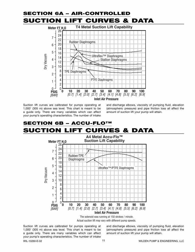
SECTION 6A – AIR-CONTROLLED
SUCTION LIFT CURVES & DATA
SECTION 6B – ACCU-FLO™
SUCTION LIFT CURVES & DATA
Suction lift curves are calibrated for pumps operating at 1,000' (305 m) above sea level. This chart is meant to be a guide only. There are many variables which can affect your pump’s operating characteristics. The number of intake
and discharge elbows, viscosity of pumping fluid, elevation (atmospheric pressure) and pipe friction loss all affect the amount of suction lift your pump will attain.
PTFE Diaphragms
[0.7] [1.4] [2.0] [2.7] [3.4] [4.1] [4.8] [5.5] [6.2] [6.9]
Ultraflex™/PTFE Diaphragms
[0.7] [1.4] [2.0] [2.7] [3.4] [4.1] [4.8] [5.5] [6.2] [6.9]
12WILDEN PUMP & ENGINEERING, LLC WIL-10260-E-02
SECTION 7A
INSTALLATION – T4 METALAIR-OPERATED PUMPSThe Model T4 Metal pump has a 38 mm (1-1/2") inlet and 32 mm (1-1/4") outlet and is designed for flows to 307 lpm (81 gpm). The T4 Metal pump is manufactured with wetted parts of aluminum, cast iron, or stainless steel. The T4 Metal pump comes with either a center block or center section. The T4 center block is constructed of aluminum or nickel-plated aluminum. The T4 center section comes in polypropylene. The air distribution system consists of a brass air valve body, aluminum piston, Glyd™ rings and a bronze center section bushing. A variety of diaphragms, valve balls, valve seats, and o-rings are available to satisfy temperature, chemical compatibility, abrasion and flex concerns.
The suction pipe size should be at least 38 mm (1-1/2") diameter or larger if highly viscous material is being pumped. The suction hose must be non-collapsible, reinforced type as the T4 is capable of pulling a high vacuum. Discharge piping should be at least 32 mm (1-1/4"); larger diameter can be used to reduce friction losses. It is critical that all fittings and connections are airtight or a reduction or loss of pump suction capability will result.
INSTALLATION: Months of careful planning, study, and selection efforts can result in unsatisfactory pump performance if installation details are left to chance.
Premature failure and long term dissatisfaction can be avoided if reasonable care is exercised throughout the installation process.
LOCATION: Noise, safety, and other logistical factors usually dictate that “utility” equipment be situated away from the production floor. Multiple installations with conflicting requirements can result in congestion of utility areas, leaving few choices for siting of additional pumps.
Within the framework of these and other existing conditions, every pump should be located in such a way that four key factors are balanced against each other to maximum advantage.
1. ACCESS: First of all, the location should be accessible. If it’s easy to reach the pump, maintenance personnel will have an easier time carrying out routine inspections and adjustments. Should major repairs become necessary, ease of access can play a key role in speeding the repair process and reducing total downtime.
2. AIR SUPPLY: Every pump location should have an air line large enough to supply the volume of air necessary to achieve the desired pumping rate (see pump performance chart). Use air pressure up to a maximum of 8.6 bar (125 psig) depending upon pumping requirements. The use of an air filter before the pump will ensure that the majority of any pipeline contaminants will be eliminated. For best results, the pumps should use an air filter, regulator, and lubricator system.
3. SOLENOID OPERATION: the pumps should use a 5µ micron air filter, needle valve and regulator. The use of an air filter before the pump will ensure that the majority of any pipeline contaminants will be eliminated.
4. ELEVATION: Selecting a site that is well within the pump’s suction lift capability will assure that loss-of-prime troubles will be eliminated. In addition, pump efficiency can be adversely affected if proper attention is not given to elevation (see pump performance chart).
5. PIPING: Final determination of the pump site should not be made until the piping problems of each possible location have been evaluated. The impact of current and future installations should be considered ahead of time to make sure that inadvertent restrictions are not created for any remaining sites.
The best choice possible will be a site involving the shortest and the straightest hook-up of suction and discharge piping. Unnecessary elbows, bends, and fittings should be avoided. Pipe sizes should be selected so as to keep friction losses within practical limits. All piping should be supported independently of the pump. In addition, it should line up without placing stress on the pump fittings.
Expansion joints can be installed to aid in absorbing the forces created by the natural reciprocating action of the pump. If the pump is to be bolted down to a solid foundation, a mounting pad placed between the pump and foundation will assist in minimizing pump vibration. Flexible connections between the pump and rigid piping will also assist in minimizing pump vibration. If quick-closing valves are installed at any point in the discharge system, or if pulsation within a system becomes a problem, a surge suppressor should be installed to protect the pump, piping and gauges from surges and water hammer.
When pumps are installed in applications involving flooded suction or suction head pressures, a gate valve should be installed in the suction line to permit closing of the line for pump service.
The T4 can be used in submersible applications only when both wetted and non-wetted portions are com patible with the material being pumped. If the pump is to be used in a submersible application, a hose should be attached to the pump’s air exhaust and the exhaust air piped above the liquid level.
If the pump is to be used in a self-priming application, be sure that all connections are airtight and that the suction lift is within the pump’s ability. Note: Materials of construction and elastomer material have an effect on suction lift parameters. Please refer to pump performance data.
Pumps in service with a positive suction head are most efficient when inlet pressure is limited to 0.5–0.7 bar (7–10 psig). Premature diaphragm failure may occur if positive suction is 0.8 bar (11 psig) and higher.
THE MODEL T4 WILL PASS 4.8 mm (3/16") SOLIDS. THE M4 STALLION WILL PASS 13 mm (1/2") SOLIDS. WHENEVER THE POSSIBILITY EXISTS THAT LARGER SOLID OBJECTS MAY BE SUCKED INTO THE PUMP, A STRAINER SHOULD BE USED ON THE SUCTION LINE.
CAUTION: DO NOT EXCEED 8.6 BAR (125 PSIG) AIR SUPPLY PRESSURE. (3.4 BAR [5O PSIG] FOR UL MODELS.)
PUMPS SHOULD BE THOROUGHLY FLUSHED WITH WATER BEFORE INSTALLING INTO PROCESS LINES. FDA AND USDA PUMPS SHOULD BE CLEANED AND/OR SANITIZED BEFORE USE ON EDIBLE PRODUCTS.
BLOW OUT AIR LINE FOR 10 TO 20 SECONDS BEFORE ATTACHING TO PUMP TO MAKE SURE ALL PIPE LINE DEBRIS IS CLEAR. ALWAYS USE AN IN-LINE AIRFILTER.
13 WILDEN PUMP & ENGINEERING, LLCWIL-10260-E-02
®
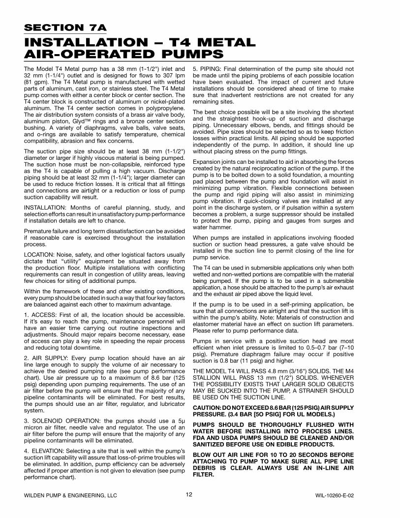
SUGGESTED INSTALLATION
SECTION 7B – AIR OPERATION
SUGGESTED OPERATION ANDMAINTENANCE INSTRUCTIONSOPERATION: Pump discharge rate can be controlled by limiting the volume and/or pressure of the air supply to the pump (preferred method). An air regulator is used to regu-late air pressure. A needle valve is used to regulate volume. Pump discharge rate can also be controlled by throttling the pump discharge by partially closing a valve in the discharge line of the pump. This action increases friction loss which reduces flow rate. This is useful when the need exists to control the pump from a remote location. When the pump discharge pressure equals or exceeds the air supply pres-sure, the pump will stop; no bypass or pressure relief valve is needed, and pump damage will not occur. The pump has reached a “deadhead” situation and can be restarted by reducing the fluid discharge pressure or increasing the air inlet pressure. The Wilden T4 pump runs solely on compressed air and does not generate heat, therefore your process fluid temperature will not be affected.
RECORDS: When service is required, a record should be made of all necessary repairs and replacements. Over a period of time, such records can become a valuable tool for predicting and preventing future maintenance problems and unscheduled downtime. In addition, accurate records make it possible to identify pumps that are poorly suited to their applications.
MAINTENANCE AND INSPECTIONS: Since each application is unique, maintenance schedules may be different for every pump. Frequency of use, line pressure, viscosity and abrasive-ness of process fluid all affect the parts life of a Wilden pump. Periodic inspections have been found to offer the best means for preventing unscheduled pump downtime. Personnel familiar with the pump’s construction and service should be informed of any abnormalities that are detected during operation.
AIR-OPERATED PUMPS: To stop the pump from operating in an emergency situation, simply close the shut-off valve (user supplied) installed in the airsupply line. A properly functioning valve will stop the air supply to the pump, therefore stopping output. This shut-off valve should be located far enough away from the pumping equipment such that it can be reached safely in an emergency situation.
Accu-Flo™ pumps: Accu-Flo™ pumps function with solenoid valves and require an electrical control circuit to supply pulses. Under normal operating conditions, the control circuit is sufficient for starting and stopping the pump. However, the shut off valve (user supplied) installed in the air supply line can be used to stop the pump if necessary. Therefore, it shoud be located far enough away from the pumping equipment such that it can be reached safely in an emergency situation.
NOTE: In the event of a power failure, the shutoff valve should be closed, if the restarting of the pump is not desirable once power is regained.
14WILDEN PUMP & ENGINEERING, LLC WIL-10260-E-02
SECTION 7D
INSTALLATION – A4 METALACCU-FLO™ PUMPSBefore installing your A4 Accu-Flo™ pump, review Section 7A for general installation suggestions including Location, Access, Air Supply, Elevation, and Piping.
The Accu-Flo™ Model A4 has a 38 mm (1-1/2") inlet and 32 mm (1-1/4") outlet and is designed for flows to 196 lpm (52 gpm). This maximum flow rate was calculated at 200 strokes per minute with 8.3 bar (120 psig) air inlet against 0 bar (0 psig) discharge head. The A4 Metal pump is manu-factured with wetted parts of polypropylene or PVDF. The center section of the A4 Metal pump is of aluminum or poly-propylene construction. A variety of diaphragms, valve balls, and o-rings are available to satisfy temperature, chemical compatibility, abrasion and flex concerns.
All wiring used to operate the pump should be placed and connected according to the proper electrical codes. It is important that the wiring is of adequate gauge to carry the current required to operate the pump. In addition, it is necessary that the electrical power supply is large enough to supply the current required to operate the pump. Wiring should be above ground level if possible (in case of fluid spill or leakage), and all wiring and connections which could become wet or damp should be made watertight.
If the pump is to be used in a self-priming application, be sure that all connections are airtight and that the suction lift is within the pump’s ability. Note: Materials of construction and elastomer material have an effect on suction lift param-eters. Please refer to pump performance data.
Pumps in service with a positive suction head are most effi-cient when inlet pressure is limited to 0.5–0.7 bar (7–10 psig). Premature diaphragm failure may occur if positive suction head is 0.8 bar (11 psig) and higher.
The solenoid valve is rated for continuous duty; however, stopping on an even number stroke count insures that the electrical power is off when pump is stopped. This practice is safer and also eliminates unwanted strokes when the system is shut down and electrical power is off.
THE MODEL A4 WILL PASS 4.8 mm (3/16") SOLIDS. THE M4 STALLION WILL PASS 13 mm (1/2") SOLIDS. WHENEVER THE POSSIBILITY EXISTS THAT LARGER SOLID OBJECTS MAY BE SUCKED INTO THE PUMP, A STRAINER SHOULD BE USED ON THE SUCTION LINE.
SECTION 7C
OPERATING PRINCIPLES BEHIND ACCU-FLO™ PUMPS
In Accu-Flo™ pump models, the standard air valve is replaced with a two position, four-way solenoid valve that has a single operator and spring return. The valve is internally air piloted for longer coil and operator life.
When the solenoid is unpowered, one air chamber is pres-surized with air, while the opposite chamber is exhausted. When electric power is applied, the solenoid shifts, and the pressurized air chamber is exhausted while the opposite chamber is pressurized. By alternately applying and remov-ing power, the solenoid-operated pump runs like a standard Wilden pump.
The speed of the pump is controlled electrically. Since each stroke is controlled by an electrical signal, the pump is ideal for batching and other electrically controlled dispensing appli-cations.
Although the speed of the pump is controlled electrically, the air pressure is important. Air pressure displaces the fluid, and if the pressure is insufficient to complete the physical stroke before an electronic impulse signals the pump to shift, the stroke will not be completed, and the displacement per stroke will be reduced. This does not harm the unit in any way, but it may cause inaccuracy when attempting to batch specific quantities with high precision if this effect is not taken into account.
There are three coil voltage options available. One coil allows for 24V DC operation. The second coil option allows for operation with either 12V DC or 24V AC at 60 Hz and the third coil option allows for 110V AC operation.
WARNING: Before installation, consult chart in Section 10B to ensure proper electrical connection.
WARNING: The solenoid valve should not be used in an area where explosion proof equipment is required unless NEMA 7 valve is specified.
There are three coil options available in both NEMA 4 and NEMA 7 ratings. One coil allows for 110V AC operation, one allows for 24V DC operation, and the third allows for either 24V AC or 12V DC operation. Consult Section 10C for refer-ence and part numbers.
15 WILDEN PUMP & ENGINEERING, LLCWIL-10260-E-02
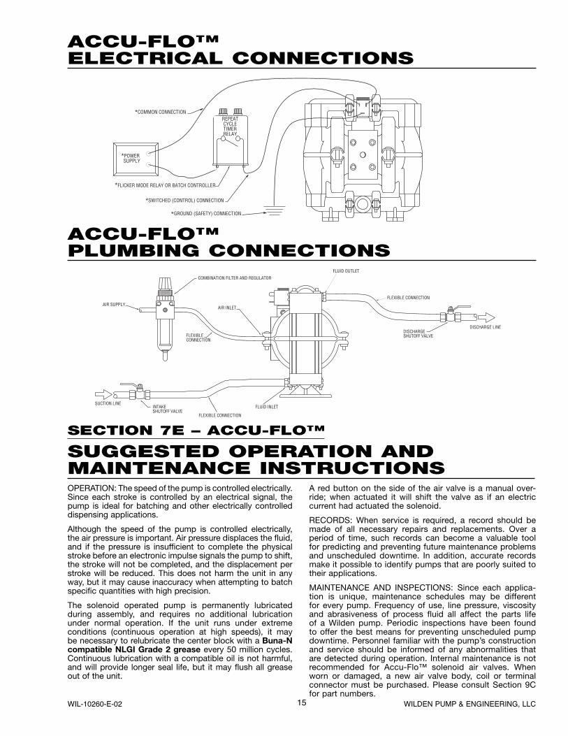
ACCU-FLO™ELECTRICAL CONNECTIONS
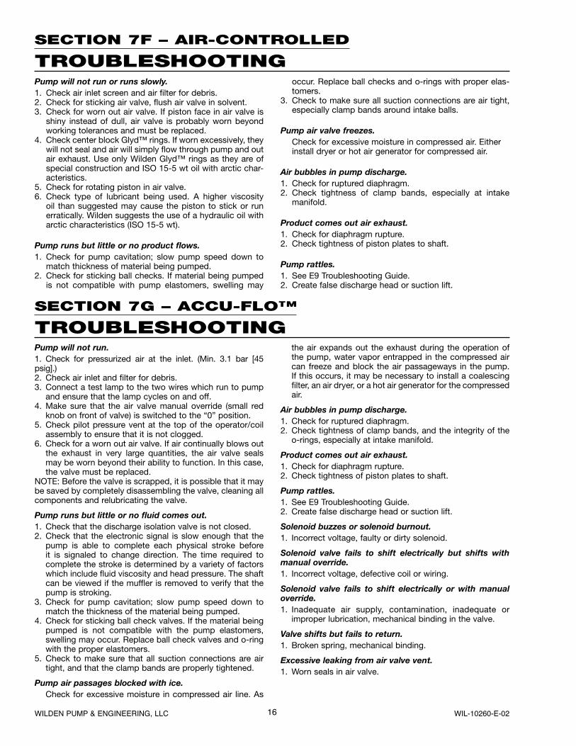
ACCU-FLO™PLUMBING CONNECTIONS
SECTION 7E – ACCU-FLO™
SUGGESTED OPERATION ANDMAINTENANCE INSTRUCTIONSOPERATION: The speed of the pump is controlled electrically. Since each stroke is controlled by an electrical signal, the pump is ideal for batching and other electrically controlled dispensing applications.
Although the speed of the pump is controlled electrically, the air pressure is important. Air pressure displaces the fluid, and if the pressure is insufficient to complete the physical stroke before an electronic impulse signals the pump to shift, the stroke will not be completed, and the displacement per stroke will be reduced. This does not harm the unit in any way, but it may cause inaccuracy when attempting to batch specific quantities with high precision.
The solenoid operated pump is permanently lubricated during assembly, and requires no additional lubrication under normal operation. If the unit runs under extreme conditions (continuous operation at high speeds), it may be necessary to relubricate the center block with a Buna-Ncompatible NLGI Grade 2 grease every 50 million cycles. Continuous lubrication with a compatible oil is not harmful, and will provide longer seal life, but it may flush all grease out of the unit.
A red button on the side of the air valve is a manual over-ride; when actuated it will shift the valve as if an electric current had actuated the solenoid.
RECORDS: When service is required, a record should be made of all necessary repairs and replacements. Over a period of time, such records can become a valuable tool for predicting and preventing future maintenance problems and unscheduled downtime. In addition, accurate records make it possible to identify pumps that are poorly suited to their applications.
MAINTENANCE AND INSPECTIONS: Since each applica-tion is unique, maintenance schedules may be different for every pump. Frequency of use, line pressure, viscosity and abrasiveness of process fluid all affect the parts life of a Wilden pump. Periodic inspections have been found to offer the best means for preventing unscheduled pump downtime. Personnel familiar with the pump’s construction and service should be informed of any abnormalities that are detected during operation. Internal maintenance is not recommended for Accu-Flo™ solenoid air valves. When worn or damaged, a new air valve body, coil or terminal connector must be purchased. Please consult Section 9C for part numbers.
16WILDEN PUMP & ENGINEERING, LLC WIL-10260-E-02
SECTION 7F – AIR-CONTROLLED
TROUBLESHOOTINGPump will not run or runs slowly.1. Check air inlet screen and air filter for debris.2. Check for sticking air valve, flush air valve in solvent.3. Check for worn out air valve. If piston face in air valve is
shiny instead of dull, air valve is probably worn beyond working tolerances and must be replaced.
4. Check center block Glyd™ rings. If worn excessively, they will not seal and air will simply flow through pump and out air exhaust. Use only Wilden Glyd™ rings as they are of special construction and ISO 15-5 wt oil with arctic char-acteristics.
5. Check for rotating piston in air valve.6. Check type of lubricant being used. A higher viscosity
oil than suggested may cause the piston to stick or run erratically. Wilden suggests the use of a hydraulic oil with arctic characteristics (ISO 15-5 wt).
Pump runs but little or no product flows.1. Check for pump cavitation; slow pump speed down to
match thickness of material being pumped.2. Check for sticking ball checks. If material being pumped
is not compatible with pump elastomers, swelling may
occur. Replace ball checks and o-rings with proper elas-tomers.
3. Check to make sure all suction connections are air tight, especially clamp bands around intake balls.
Pump air valve freezes.Check for excessive moisture in compressed air. Either install dryer or hot air generator for compressed air.
Air bubbles in pump discharge.1. Check for ruptured diaphragm.2. Check tightness of clamp bands, especially at intake
manifold.
Product comes out air exhaust.1. Check for diaphragm rupture.2. Check tightness of piston plates to shaft.
Pump rattles.1. See E9 Troubleshooting Guide.2. Create false discharge head or suction lift.
SECTION 7G – ACCU-FLO™
TROUBLESHOOTINGPump will not run.1. Check for pressurized air at the inlet. (Min. 3.1 bar [45 psig].)2. Check air inlet and filter for debris.3. Connect a test lamp to the two wires which run to pump
and ensure that the lamp cycles on and off.4. Make sure that the air valve manual override (small red
knob on front of valve) is switched to the “0” position.5. Check pilot pressure vent at the top of the operator/coil
assembly to ensure that it is not clogged.6. Check for a worn out air valve. If air continually blows out
the exhaust in very large quantities, the air valve seals may be worn beyond their ability to function. In this case, the valve must be replaced.
NOTE: Before the valve is scrapped, it is possible that it may be saved by completely disassembling the valve, cleaning all components and relubricating the valve.
Pump runs but little or no fluid comes out.1. Check that the discharge isolation valve is not closed.2. Check that the electronic signal is slow enough that the
pump is able to complete each physical stroke before it is signaled to change direction. The time required to complete the stroke is determined by a variety of factors which include fluid viscosity and head pressure. The shaft can be viewed if the muffler is removed to verify that the pump is stroking.
3. Check for pump cavitation; slow pump speed down to match the thickness of the material being pumped.
4. Check for sticking ball check valves. If the material being pumped is not compatible with the pump elastomers, swelling may occur. Replace ball check valves and o-ring with the proper elastomers.
5. Check to make sure that all suction connections are air tight, and that the clamp bands are properly tightened.
Pump air passages blocked with ice.Check for excessive moisture in compressed air line. As
the air expands out the exhaust during the operation of the pump, water vapor entrapped in the compressed air can freeze and block the air passageways in the pump. If this occurs, it may be necessary to install a coalescing filter, an air dryer, or a hot air generator for the compressed air.
Air bubbles in pump discharge.1. Check for ruptured diaphragm.2. Check tightness of clamp bands, and the integrity of the
o-rings, especially at intake manifold.
Product comes out air exhaust.1. Check for diaphragm rupture.2. Check tightness of piston plates to shaft.
Pump rattles.1. See E9 Troubleshooting Guide.2. Create false discharge head or suction lift.
Solenoid buzzes or solenoid burnout.1. Incorrect voltage, faulty or dirty solenoid.
Solenoid valve fails to shift electrically but shifts with manual override.1. Incorrect voltage, defective coil or wiring.
Solenoid valve fails to shift electrically or with manual override.1. Inadequate air supply, contamination, inadequate or
improper lubrication, mechanical binding in the valve.
Valve shifts but fails to return.1. Broken spring, mechanical binding.
Excessive leaking from air valve vent.1. Worn seals in air valve.
17 WILDEN PUMP & ENGINEERING, LLCWIL-10260-E-02
SECTION 8A
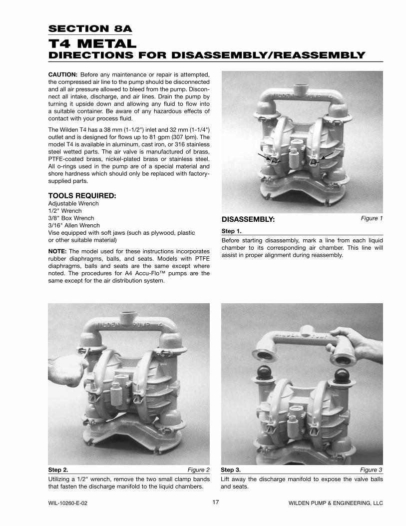
T4 METALDIRECTIONS FOR DISASSEMBLY/REASSEMBLY
Figure 1
Step 2. Figure 2
Utilizing a 1/2" wrench, remove the two small clamp bands that fasten the discharge manifold to the liquid chambers.
Step 3. Figure 3
Lift away the discharge manifold to expose the valve balls and seats.
CAUTION: Before any maintenance or repair is attempted, the compressed air line to the pump should be disconnected and all air pressure allowed to bleed from the pump. Discon-nect all intake, discharge, and air lines. Drain the pump by turning it upside down and allowing any fluid to flow into a suitable container. Be aware of any hazardous effects of contact with your process fluid.
The Wilden T4 has a 38 mm (1-1/2") inlet and 32 mm (1-1/4") outlet and is designed for flows up to 81 gpm (307 lpm). The model T4 is available in aluminum, cast iron, or 316 stainless steel wetted parts. The air valve is manufactured of brass, PTFE-coated brass, nickel-plated brass or stainless steel. All o-rings used in the pump are of a special material and shore hardness which should only be replaced with factory-supplied parts.
TOOLS REQUIRED:Adjustable Wrench1/2" Wrench3/8" Box Wrench3/16" Allen WrenchVise equipped with soft jaws (such as plywood, plasticor other suitable material)
NOTE: The model used for these instructions incorporates rubber diaphragms, balls, and seats. Models with PTFE diaphragms, balls and seats are the same except where noted. The procedures for A4 Accu-Flo™ pumps are the same except for the air distribution system.
DISASSEMBLY:
Step 1.
Before starting disassembly, mark a line from each liquid chamber to its corresponding air chamber. This line will assist in proper alignment during reassembly.
18WILDEN PUMP & ENGINEERING, LLC WIL-10260-E-02
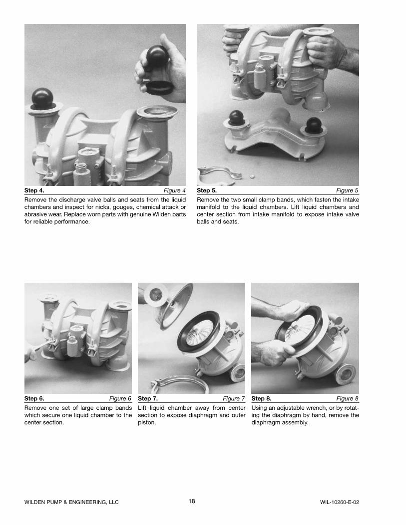
Step 6. Figure 6
Remove one set of large clamp bands which secure one liquid chamber to the center section.
Step 7. Figure 7
Lift liquid chamber away from center section to expose diaphragm and outer piston.
Step 8. Figure 8
Using an adjustable wrench, or by rotat-ing the diaphragm by hand, remove the diaphragm assembly.
Step 4. Figure 4
Remove the discharge valve balls and seats from the liquid chambers and inspect for nicks, gouges, chemical attack or abrasive wear. Replace worn parts with genuine Wilden parts for reliable performance.
Step 5. Figure 5
Remove the two small clamp bands, which fasten the intake manifold to the liquid chambers. Lift liquid chambers and center section from intake manifold to expose intake valve balls and seats.
19 WILDEN PUMP & ENGINEERING, LLCWIL-10260-E-02
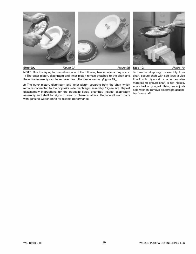
Step 9A. Figure 9A
NOTE: Due to varying torque values, one of the following two situations may occur: 1) The outer piston, diaphragm and inner piston remain attached to the shaft and the entire assembly can be removed from the center section (Figure 9A);
2) The outer piston, diaphragm and inner piston separate from the shaft which remains connected to the opposite side diaphragm assembly (Figure 9B). Repeat disassembly instructions for the opposite liquid chamber. Inspect diaphragm assembly and shaft for signs of wear or chemical attack. Replace all worn parts with genuine Wilden parts for reliable performance.
Figure 9B Step 10. Figure 10
To remove diaphragm assembly from shaft, secure shaft with soft jaws (a vise fitted with plywood or other suitable material) to ensure shaft is not nicked, scratched or gouged. Using an adjust-able wrench, remove diaphragm assem-bly from shaft.
20WILDEN PUMP & ENGINEERING, LLC WIL-10260-E-02
Figure C
Figure B
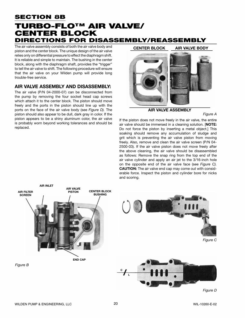
END CAP
AIR FILTERSCREEN
AIR VALVEPISTON CENTER BLOCK
BUSHING
AIR INLET
Figure D
Figure AAIR VALVE ASSEMBLY
CENTER BLOCK AIR VALVE BODYThe air valve assembly consists of both the air valve body and piston and the center block. The unique design of the air valve relies only on differential pressure to effect the diaphragm shift. It is reliable and simple to maintain. The bushing in the center block, along with the diaphragm shaft, provides the “trigger” to tell the air valve to shift. The following procedure will ensure that the air valve on your Wilden pump will provide longtrouble-free service.
If the piston does not move freely in the air valve, the entire air valve should be immersed in a cleaning solution. [NOTE:Do not force the piston by inserting a metal object.] This soaking should remove any accumulation of sludge and grit which is preventing the air valve piston from moving freely. Also, remove and clean the air valve screen (P/N 04-2500-03). If the air valve piston does not move freely after the above cleaning, the air valve should be disassembled as follows: Remove the snap ring from the top end of the air valve cylinder and apply an air jet to the 3/16-inch hole on the opposite end of the air valve face (see Figure C). CAUTION: The air valve end cap may come out with consid-erable force. Inspect the piston and cylinder bore for nicks and scoring.
AIR VALVE ASSEMBLY AND DISASSEMBLY:The air valve (P/N 04-2000-07) can be disconnected from the pump by removing the four socket head cap screws which attach it to the center block. The piston should move freely and the ports in the piston should line up with the ports on the face of the air valve body (see Figure D). Thepiston should also appear to be dull, dark gray in color. If the piston appears to be a shiny aluminum color, the air valve is probably worn beyond working tolerances and should be replaced.
SECTION 8B
TURBO-FLO™ AIR VALVE/CENTER BLOCKDIRECTIONS FOR DISASSEMBLY/REASSEMBLY
21 WILDEN PUMP & ENGINEERING, LLCWIL-10260-E-02
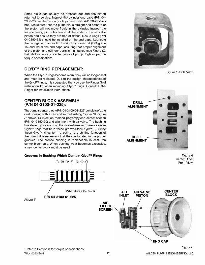
Figure E
Grooves In Bushing Which Contain Glyd™ Rings
P/N 04-3100-01-225
P/N 04-3800-09-07
Figure H
AIR VALVE PISTON
CENTERBLOCK
END CAP
AIRINLET
AIRFILTER
SCREEN
DRILLALIGNMENT
DRILLALIGNMENT
Figure GCenter Block
(Front View)
Figure F (Side View)
Small nicks can usually be dressed out and the piston returned to service. Inspect the cylinder end caps (P/N 04-2300-23 has the piston guide pin and P/N 04-2330-23 does not.) Make sure that the guide pin is straight and smooth or the piston will not move freely in the cylinder. Inspect the anti-centering pin holes found at the ends of the air valve piston and ensure they are free of debris. New o-rings (P/N 04-2390-52) should be installed on the end caps. Lubricate the o-rings with an arctic 5 weight hydraulic oil (ISO grade 15) and install the end caps, assuring that proper alignment of the piston and cylinder ports is maintained (see Figure D). Reinstall air valve to center block of pump. Tighten per the torque specification*.
GLYD™ RING REPLACEMENT:When the Glyd™ rings become worn, they will no longer seal and must be replaced. Due to the design characteristics of the Glyd™ rings, it is suggested that you use the Ringer Seal installation kit when replacing Glyd™ rings. Consult EOM-Ringer for installation instructions.
CENTER BLOCK ASSEMBLY(P/N 04-3100-01-225):The pump’s center block (P/N 04-3100-01-225) consists of a die cast housing with a cast-in-bronze bushing (Figure G). Figure H shows T4 injection-molded polypropylene center section(P/N 04-3150-20) and alignment with air valve. The bushing has eleven grooves cut on the inside diameter. There are sevenGlyd™ rings that fit in these grooves (see Figure E). Sincethese Glyd™ rings form a part of the shifting function of the pump, it is necessary that they be located in the proper grooves. The bronze bushing is replaceable in cast iron center block only. When bushing wear becomes excessive, a new center block must be used.
*Refer to Section 8 for torque specifications.
22WILDEN PUMP & ENGINEERING, LLC WIL-10260-E-02
SECTION 8C
REASSEMBLY HINTS & TIPS
ASSEMBLY:Upon performing applicable maintenance to the air distribu-tion system, the pump can now be reassembled. Please refer to the disassembly instructions for photos and parts placement. To reassemble the pump, follow the disassem-bly instructions in reverse order. The air distribution system needs to be assembled first, then the diaphragms and finally the wetted path. Please find the applicable torque speci-fications on this page. The following tips will assist in the assembly process.
• Clean the inside of the center section shaft bushing to ensure no damage is done to new seals.
• Stainless bolts should be lubed to reduce the possibility of seizing during tightening.
• Be sure to tighten outer pistons simultaneously on PTFE-fitted pumps to ensure proper torque values.
MAXIMUM TORQUE SPECIFICATIONS
Description of Part Metal Pumps
Air Valve 3.4 N·m [30 in-lbs]
Outer Piston 54.2 N·m [40 ft-lbs]
Small Clamp Band 3.4 N·m [30 in-lbs]
Large Clamp Band (Rubber-Fitted) 10.7 N·m [95 in-lbs]
Large Clamp Band (PTFE-Fitted) 13.5 N·m [120 in-lbs]
Center Block Assembly 8.5 N·m [75 in-lbs]
Polyurethane Screen Base 2.3 N·m [20 in-lbs]
23 WILDEN PUMP & ENGINEERING, LLCWIL-10260-E-02
SECTION 8D
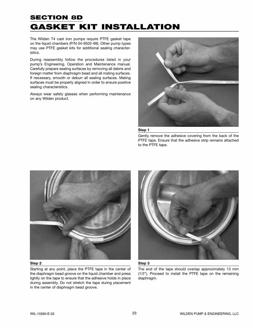
GASKET KIT INSTALLATION
Step 1
Gently remove the adhesive covering from the back of the PTFE tape. Ensure that the adhesive strip remains attached to the PTFE tape.
Step 2
Starting at any point, place the PTFE tape in the center of the diaphragm bead groove on the liquid chamber and press lightly on the tape to ensure that the adhesive holds in place during assembly. Do not stretch the tape during placement in the center of diaphragm bead groove.
Step 3
The end of the tape should overlap approximately 13 mm (1/2"). Proceed to install the PTFE tape on the remaining diaphragm.
The Wilden T4 cast iron pumps require PTFE gasket tape on the liquid chambers (P/N 04-9502-99). Other pump types may use PTFE gasket kits for additional sealing character-istics.
During reassembly follow the procedures listed in your pump’s Engineering, Operation and Maintenance manual. Carefully prepare sealing surfaces by removing all debris and foreign matter from diaphragm bead and all mating surfaces. If necessary, smooth or deburr all sealing surfaces. Mating surfaces must be properly aligned in order to ensure positive sealing characteristics.
Always wear safety glasses when performing maintenance on any Wilden product.
24WILDEN PUMP & ENGINEERING, LLC WIL-10260-E-02
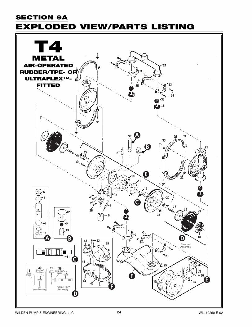
SECTION 9A
EXPLODED VIEW/PARTS LISTING
T4METAL
AIR-OPERATEDRUBBER/TPE- OR
ULTRAFLEX™-FITTED
25 WILDEN PUMP & ENGINEERING, LLCWIL-10260-E-02
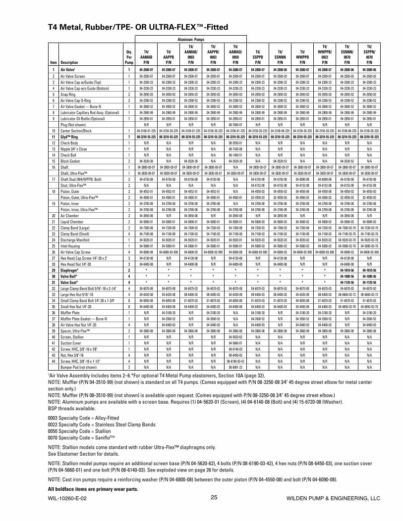
T4 Metal, Rubber/TPE- OR ULTRA-FLEX™-Fitted
Aluminum Pumps
Item Description
Qty. Per
Pump
T4/AAMAB
P/N
T4/AAPPB
P/N
T4/AAMAB/
0003P/N
T4/AAPPB/
0003P/N
T4/AAMAD/
0050P/N
T4/SSPPB
P/N
T4/SSNNN
P/N
T4/WWPPB
P/N
T4/WWPPB/
0022P/N
T4/SSNNN/
0070P/N
T4/SSPPN/
0070P/N
1 Air Valve1 1 04-2000-07 04-2000-07 04-2000-07 04-2000-07 04-2080-07 04-2000-07 04-2000-06 04-2000-07 04-2000-07 04-2000-06 04-2000-06
2 Air Valve Screen 1 04-2500-07 04-2500-07 04-2500-07 04-2500-07 04-2500-07 04-2500-07 04-2500-03 04-2500-07 04-2500-07 04-2500-03 04-2500-03
3 Air Valve Cap w/Guide (Top) 1 04-2300-23 04-2300-23 04-2300-23 04-2300-23 04-2300-23 04-2300-23 04-2300-23 04-2300-23 04-2300-23 04-2300-23 04-2300-23
4 Air Valve Cap w/o Guide (Bottom) 1 04-2330-23 04-2330-23 04-2330-23 04-2330-23 04-2330-23 04-2330-23 04-2330-23 04-2330-23 04-2330-23 04-2330-23 04-2330-23
5 Snap Ring 2 04-2650-03 04-2650-03 04-2650-03 04-2650-03 04-2650-03 04-2650-03 04-2650-03 04-2650-03 04-2650-03 04-2650-03 04-2650-03
6 Air Valve Cap O-Ring 2 04-2390-52 04-2390-52 04-2390-52 04-2390-52 04-2390-52 04-2390-52 04-2390-52 04-2390-52 04-2390-52 04-2390-52 04-2390-52
7 Air Valve Gasket — Buna-N 1 04-2600-52 04-2600-52 04-2600-52 04-2600-52 04-2600-52 04-2600-52 04-2600-52 04-2600-52 04-2600-52 04-2600-52 04-2600-52
8 Lubricator Capillary Rod Assy. (Optional) 1 04-2900-99 04-2900-99 04-2900-99 04-2900-99 04-2900-99 04-2900-99 04-2900-99 04-2900-99 04-2900-99 04-2900-99 04-2900-99
9 Lubricator Oil Bottle (Optional) 1 04-2850-01 04-2850-01 04-2850-01 04-2850-01 04-2850-01 04-2850-01 04-2850-01 04-2850-01 04-2850-01 04-2850-01 04-2850-01
Plug (Not shown) N/R N/R N/R N/R 08-7000-07 N/R N/R N/R N/R N/R N/R
10 Center Section/Block 1 04-3100-01-225 04-3150-20-225 04-3100-01-225 04-3150-20-225 04-3100-01-225 04-3150-20-225 04-3100-06-225 04-3150-20-225 04-3150-20-225 04-3100-06-225 04-3150-20-225
11 Glyd™ Ring 7 08-3210-55-225 08-3210-55-225 08-3210-55-225 08-3210-55-225 08-3210-55-225 08-3210-55-225 08-3210-55-225 08-3210-55-225 08-3210-55-225 08-3210-55-225 08-3210-55-225
12 Check Body 1 N/R N/A N/R N/A 08-3550-01 N/A N/R N/A N/A N/R N/A
13 Nipple 3⁄4" x Close 1 N/R N/A N/R N/A 08-7420-08 N/A N/R N/A N/A N/R N/A
14 Check Ball 1 N/R N/A N/R N/A 08-1450-51 N/A N/R N/A N/A N/R N/A
15 Block Gasket 2 04-3520-30 N/A 04-3520-30 N/A 04-3520-30 N/A 04-3520-52 N/A N/A 04-3520-52 N/A
16 Shaft 1 04-3800-09-07 04-3800-09-07 04-3800-09-07 04-3800-09-07 N/A 04-3800-09-07 04-3800-09-07 04-3800-09-07 04-3800-09-07 04-3800-09-07 04-3800-09-07
Shaft, Ultra-Flex™ 1 04-3830-09-07 04-3830-09-07 04-3830-09-07 04-3830-09-07 04-3830-09-07 04-3830-09-07 04-3830-09-07 04-3830-09-07 04-3830-09-07 04-3830-09-07 04-3830-09-07
17 Shaft Stud (M4/WPPB: Bolt) 2 04-6150-08 04-6150-08 04-6150-08 04-6150-08 N/A 04-6150-08 04-6150-08 04-6090-08 04-6090-08 04-6150-08 04-6150-08
Stud, Ultra-Flex™ 2 N/A N/A N/A N/A N/A 04-6152-08 04-6152-08 04-6152-08 04-6152-08 04-6152-08 04-6152-08
18 Piston, Outer 2 04-4552-01 04-4552-01 04-4552-01 04-4552-01 N/A 04-4550-03 04-4550-03 04-4550-08 04-4550-08 04-4550-03 04-4550-03
Piston, Outer, Ultra-Flex™ 2 04-4560-01 04-4560-01 04-4560-01 04-4560-01 04-4560-01 02-4550-03 02-4550-03 04-4560-02 04-4560-02 02-4550-03 02-4550-03
19 Piston, Inner 2 04-3700-08 04-3700-08 04-3700-08 04-3700-08 N/A 04-3700-08 04-3700-08 04-3700-08 04-3700-08 04-3700-08 04-3700-08
Piston, Inner, Ultra-Flex™ 2 04-3760-08 04-3760-08 04-3760-08 04-3760-08 04-3760-08 04-3760-08 04-3760-08 04-3760-08 04-3760-08 04-3760-08 04-3760-08
20 Air Chamber 2 04-3650-08 N/R 04-3650-08 N/R 04-3650-08 N/R 04-3650-06 N/R N/R 04-3650-06 N/R
21 Liquid Chamber 2 04-5000-01 04-5000-01 04-5000-01 04-5000-01 04-5000-01 04-5000-03 04-5000-03 04-5000-02 04-5000-02 04-5000-03 04-5000-03
22 Clamp Band (Large) 2 04-7300-08 04-7330-08 04-7300-03 04-7330-03 04-7300-08 04-7330-03 04-7300-03 04-7330-08 04-7330-03 04-7300-03-70 04-7330-03-70
23 Clamp Band (Small) 4 04-7100-08 04-7100-08 04-7100-03 04-7100-03 04-7100-08 04-7100-03 04-7100-03 04-7100-08 04-7100-03 04-7100-03-70 04-7100-03-70
24 Discharge Manifold 1 04-5020-01 04-5020-01 04-5020-01 04-5020-01 04-5020-01 04-5020-03 04-5020-03 04-5020-02 04-5020-02 04-5020-03-70 04-5020-03-70
25 Inlet Housing 1 04-5080-01 04-5080-01 04-5080-01 04-5080-01 04-5080-01 04-5080-03 04-5080-03 04-5080-02 04-5080-02 04-5080-03-70 04-5080-03-70
26 Air Valve Cap Screw 4 04-6000-08 04-6000-03-500 04-6000-03 04-6000-03-500 04-6000-08 04-6000-03-500 04-6000-03 04-6000-03-500 04-6000-03-500 04-6000-03 04-6000-03-500
27 Hex Head Cap Screw 1⁄4"-20 x 3" 3 04-6130-08 N/R 04-6130-08 N/R 04-6130-08 N/R 04-6130-08 N/R N/R 04-6130-08 N/R
28 Hex Head Nut 1⁄4"-20 3 04-6400-08 N/R 04-6400-08 N/R 04-6400-08 N/R 04-6400-08 N/R N/R 04-6400-08 N/R
29 Diaphragm* 2 * * * * * * * * * 04-1010-56 04-1010-56
30 Valve Ball* 4 * * * * * * * * * 04-1080-56 04-1080-56
31 Valve Seat* 4 * * * * * * * * * 04-1120-56 04-1120-56
32 Large Clamp Band Bolt 5⁄16"-18 x 2-1⁄4" 4 04-6070-08 04-6070-08 04-6070-03 04-6070-03 04-6070-08 04-6070-03 04-6070-03 04-6070-08 04-6070-03 04-6070-03 04-6070-03
33 Large Hex Nut 5⁄16"-18 4 04-6420-08 04-6420-08 08-6400-03 08-6400-03 04-6420-08 08-6400-03 08-6400-03 04-6420-08 08-6400-03 08-6660-03-72 08-6660-03-72
34 Small Clamp Band Bolt 1⁄4"-20 x 1-3⁄4" 8 04-6050-08 04-6050-08 01-6070-03 01-6070-03 04-6050-08 01-6070-03 01-6070-03 04-6050-08 01-6070-03 01-6070-03 01-6070-03
35 Small Hex Nut 1⁄4"-20 8 04-6400-08 04-6400-08 04-6400-03 04-6400-03 04-6400-08 04-6400-03 04-6400-03 04-6400-08 04-6400-03 04-6650-03-70 04-6650-03-70
36 Muffler Plate 1 N/R 04-3180-20 N/R 04-3180-20 N/A 04-3180-20 N/R 04-3180-20 04-3180-20 N/R 04-3180-20
37 Muffl er Plate Gasket — Buna-N 1 N/R 04-3500-52 N/R 04-3500-52 N/A 04-3500-52 N/R 04-3500-52 04-3500-52 N/R 04-3500-52
38 Air Valve Hex Nut 1⁄4"-20 4 N/R 04-6400-03 N/R 04-6400-03 N/A 04-6400-03 N/R 04-6400-03 04-6400-03 N/R 04-6400-03
39 Spacer, Ultra-Flex™ 2 04-3860-08 04-3860-08 04-3860-08 04-3860-08 04-3860-08 04-3860-08 04-3860-08 04-3860-08 04-3860-08 04-3860-08 04-3860-08
40 Screen, Stallion 1 N/R N/R N/R N/R 04-5620-62 N/A N/A N/R N/R N/A N/A
41 Suction Cover 1 N/R N/R N/R N/R 04-5660-01 N/A N/A N/R N/R N/A N/A
42 Screw, HHC, 3/8"-16 x 7⁄8" 1 N/R N/R N/R N/R 08-6140-03 N/A N/A N/R N/R N/A N/A
43 Nut, Hex 3/8"-16 4 N/R N/R N/R N/R 08-6450-03 N/A N/A N/R N/R N/A N/A
44 Screw, HHC, 3/8"-16 x 1-1⁄2" 4 N/R N/R N/R N/R 08-6190-03-42 N/A N/A N/R N/R N/A N/A
Bumper Pad (not shown) 2 N/A N/A N/A N/A 08-6901-23 N/A N/A N/A N/A N/A N/A
1Air Valve Assembly includes items 2–6.*For optional T4 Metal Pump elastomers, Section 10A (page 32).NOTE: Muffl er (P/N 04-3510-99) (not shown) is standard on all T4 pumps. (Comes equipped with P/N 08-3250-08 3⁄4" 45 degree street elbow for metal center section only.)NOTE: Muffl er (P/N 08-3510-99) (not shown) is available upon request. (Comes equipped with P/N 08-3250-08 3⁄4" 45 degree street elbow.)NOTE: Aluminum pumps are available with a screen base. Requires (1) 04-5620-01 (Screen), (4) 04-6140-08 (Bolt) and (4) 15-6720-08 (Washer).BSP threads available.
0003 Specialty Code = Alloy-Fitted0022 Specialty Code = Stainless Steel Clamp Bands0050 Specialty Code = Stallion0070 Specialty Code = Sanifl oFDA
NOTE: Stallion models come standard with rubber Ultra-Flex™ diaphragms only.See Elastomer Section for details.
NOTE: Stallion model pumps require an additional screen base (P/N 04-5620-62), 4 bolts (P/N 08-6190-03-42), 4 hex nuts (P/N 08-6450-03), one suction cover (P/N 04-5660-01) and one bolt (P/N 08-6140-03). See exploded view on page 26 for details.
NOTE: Cast iron pumps require a reinforcing washer (P/N 04-6800-08) between the outer piston (P/N 04-4550-08) and bolt (P/N 04-6090-08).
All boldface items are primary wear parts.
26WILDEN PUMP & ENGINEERING, LLC WIL-10260-E-02
PTFEAssembly
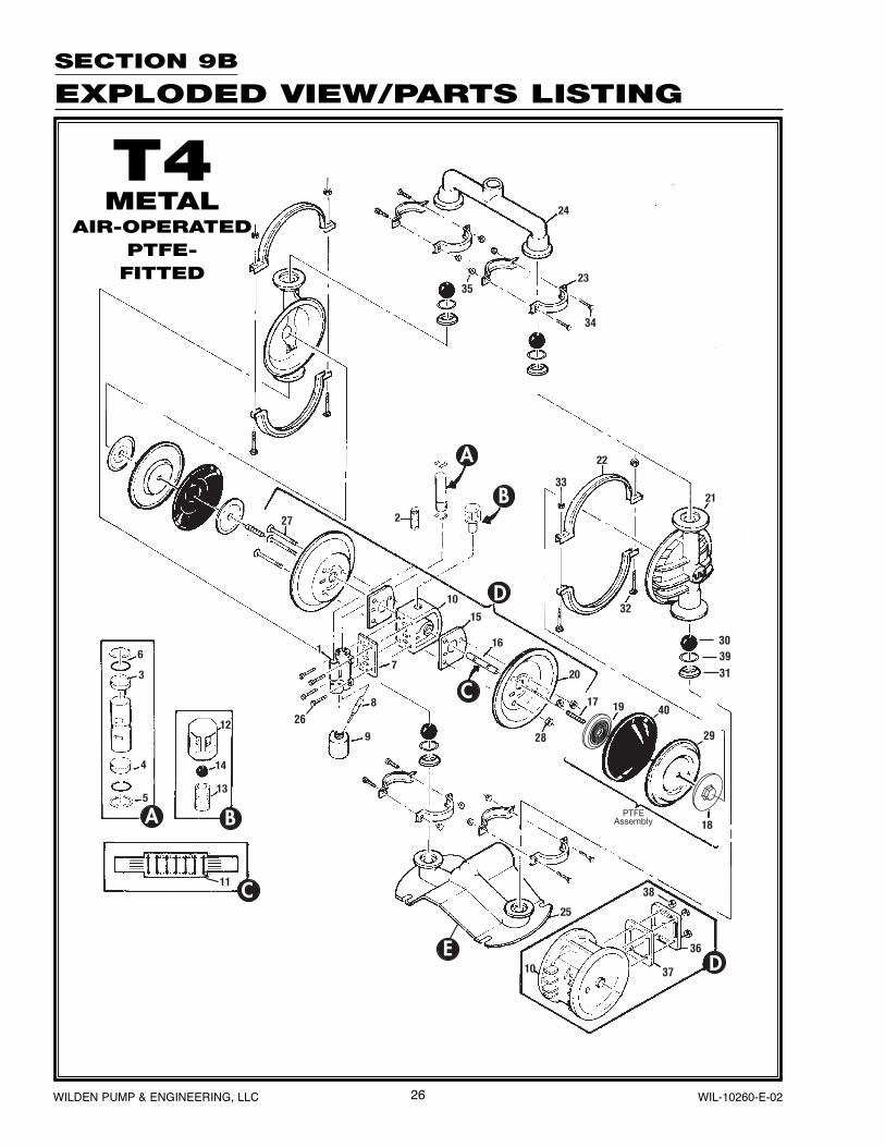
SECTION 9B
EXPLODED VIEW/PARTS LISTING
T4METAL
AIR-OPERATEDPTFE-
FITTED
27 WILDEN PUMP & ENGINEERING, LLCWIL-10260-E-02
T4 Metal, PTFE-Fitted
Item Description
Qty. Per
Pump
T4/AAPPB
P/N
T4/AAPPB/0003
P/N
T4/SSPPB
P/N
T4/WWPPB
P/N
T4/SSNNN/0070
P/N
T4/SSPPN/0070
P/N1 Air Valve1 1 04-2000-07 04-2000-07 04-2000-07 04-2000-07 04-2000-06 04-2000-062 Air Valve Screen 1 04-2500-07 04-2500-07 04-2500-07 04-2500-07 04-2500-03 04-2500-033 Air Valve Cap w/Guide (Top) 1 04-2300-23 04-2300-23 04-2300-23 04-2300-23 04-2300-23 04-2300-234 Air Valve Cap w/o Guide (Bottom) 1 04-2330-23 04-2330-23 04-2330-23 04-2330-23 04-2330-23 04-2330-235 Snap Ring 2 04-2650-03 04-2650-03 04-2650-03 04-2650-03 04-2650-03 04-2650-036 Air Valve Cap O-Ring 2 04-2390-52 04-2390-52 04-2390-52 04-2390-52 04-2390-52 04-2390-527 Air Valve Gasket — Buna-N 1 04-2600-52 04-2600-52 04-2600-52 04-2600-52 04-2600-52 04-2600-528 Lubricator Capillary Rod Assy. (Optional) 1 04-2900-99 04-2900-99 04-2900-99 04-2900-99 04-2900-99 04-2900-999 Lubricator Oil Bottle (Optional) 1 04-2850-01 04-2850-01 04-2850-01 04-2850-01 04-2850-01 04-2850-01
10 Center Block/Section 1 04-3150-20-225 04-3150-20-225 04-3150-20-225 04-3150-20-225 04-3100-06-225 04-3150-20-22511 Glyd™ Ring 7 08-3210-55-225 08-3210-55-225 08-3210-55-225 08-3210-55-225 08-3210-55-225 08-3210-55-22512 Check Body 1 N/A N/A N/A N/A N/R N/A13 Nipple 3⁄4" x Close 1 N/A N/A N/A N/A N/R N/A14 Check Ball 1 N/A N/A N/A N/A N/R N/A15 Block Gasket — Buna-N 2 N/A N/A N/A N/A 04-3520-52 N/A16 Shaft 1 04-3820-09-07 04-3820-09-07 04-3820-09-07 04-3820-09-07 04-3820-09-07 04-3820-09-0717 Shaft Stud 2 04-6150-08 04-6150-08 04-6150-08 04-6150-08 04-6150-08 04-6150-0818 Piston, Outer 2 04-4600-01 04-4600-01 04-4600-03 04-4600-03 04-4600-03 04-4600-0319 Piston, Inner 2 04-3750-01 04-3750-01 04-3750-01 04-3750-01 04-3750-01 04-3750-0120 Air Chamber 2 N/R N/R N/R N/R 04-3650-06 N/R21 Liquid Chamber 2 04-5000-01 04-5000-01 04-5000-03 04-5000-02 04-5000-03 04-5000-0322 Clamp Band (Large) 2 04-7330-03 04-7330-03 04-7330-03 04-7330-03 04-7300-03-70 04-7330-03-7023 Clamp Band (Small) 4 04-7100-03 04-7100-03 04-7100-03 04-7100-03 04-7100-03-70 04-7100-03-7024 Discharge Manifold 1 04-5020-01 04-5020-01 04-5020-03 04-5020-02 04-5020-03-70 04-5020-03-7025 Inlet Housing 1 04-5080-01 04-5080-01 04-5080-03 04-5080-02 04-5080-03-70 04-5080-03-7026 Air Valve Cap Screw 1⁄4"-20 x 6-11⁄16" 4 04-6000-03-500 04-6000-03-500 04-6000-03-500 04-6000-03-500 04-6000-03 04-6000-03-50027 Hex Head Cap Screw 1⁄4"-20 x 3" 3 N/R N/R N/R N/R 04-6130-08 N/R28 Hex Head Nut 1⁄4"-20 3 N/R N/R N/R N/R 04-6400-08 N/R29 Diaphragm 2 04-1010-55 04-1010-55 04-1010-55 04-1010-55 04-1010-55 04-1010-5530 Valve Ball 4 04-1080-55 04-1080-55 04-1080-55 04-1080-55 04-1080-55 04-1080-5531 Valve Seat 4 04-1121-01 04-1121-01 04-1121-03 04-1121-08 04-1121-03 04-1121-0332 Large Clamp Band Bolt 5⁄16"-18 x 2-1⁄4" 4 04-6070-03 04-6070-03 04-6070-03 04-6070-03 04-6070-03 04-6070-0333 Large Hex Nut 5⁄16"-18 4 08-6400-03 08-6400-03 08-6400-03 08-6400-03 08-6660-03-72 08-6660-03-7234 Small Clamp Band Bolt 1⁄4"-20 x 1-3⁄4" 8 01-6070-03 01-6070-03 01-6070-03 01-6070-03 01-6070-03 01-6070-0335 Small Hex Nut 1⁄4"-20 8 04-6400-03 04-6400-03 04-6400-03 04-6400-03 04-6650-03-70 04-6650-03-7036 Muffler Plate 1 04-3180-20 04-3180-20 04-3180-20 04-3180-20 N/R 04-3180-2037 Muffler Plate Gasket — Buna-N 1 04-3500-52 04-3500-52 04-3500-52 04-3500-52 N/R 04-3500-5238 Air Valve Hex Nut 1⁄4"-20 4 04-6400-03 04-6400-03 04-6400-03 04-6400-03 N/R 04-6400-0339 Valve Seat O-Ring2 4 04-1200-55 04-1200-55 04-1200-55 04-1200-55 04-1200-55 04-1200-5540 Back-up Diaphragm* 2 04-1060-51 04-1060-51 04-1060-51 04-1060-51 04-1060-51 04-1060-51
1Air Valve Assembly includes items 2–6.2Fluoro-Seal™ o-rings available upon request.NOTE — Muffl er (P/N 04-3510-99) (not shown) is standard on all pumps. (Metal center blocks come with a 45° street elbow.)* Back-up Diaphragm for PTFE-fi tted pump: P/N 04-1060-51. Sanifl ex™ Back-up Diaphragm, P/N 04-1060-56, is available upon request for PTFE-fi tted pumps.
Please consult your local distributor.All PTFE fi tted cast iron pumps require 1/2" gasket tape P/N 04-9502-99BSP threads available.
0003 Specialty Code = Alloy-Fitted0070 Specialty Code = Sanifl oFDA
All boldface items are primary wear parts.
28WILDEN PUMP & ENGINEERING, LLC WIL-10260-E-02
SECTION 9C
EXPLODED VIEW/PARTS LISTING
A4METAL
ACCU-FLO™
29 WILDEN PUMP & ENGINEERING, LLCWIL-10260-E-02
A4 Metal Accu-Flo™
Rubber-Fitted PTFE-Fitted
Item Description
Qty. Per
Pump
A4/AAMAA/0150
P/N
A4/HHPPA/0150
P/N
A4/SSPPA/0150
P/N
A4/WWPPA/0150
P/N
A4/AAPPA/0150
P/N
A4/HHPPA/0150
P/N
A4/SSPPA/0150
P/N
A4/WSPPA/0150
P/N
1 Solenoid Valve Assembly 1 04-2000-99-150 04-2000-99-150 04-2000-99-150 04-2000-99-150 04-2000-99-150 04-2000-99-150 04-2000-99-150 04-2000-99-150
2 Main Valve Body 1 04-2000-01-150 04-2000-01-150 04-2000-01-150 04-2000-01-150 04-2000-01-150 04-2000-01-150 04-2000-01-150 04-2000-01-1503 Coil 1 00-2110-99-150 00-2110-99-150 00-2110-99-150 00-2110-99-150 00-2110-99-150 00-2110-99-150 00-2110-99-150 00-2110-99-1504 Terminal Connector 1 00-2130-99 00-2130-99 00-2130-99 00-2130-99 00-2130-99 00-2130-99 00-2130-99 00-2130-995 Air Valve Gasket — Buna-N 1 04-2600-52 04-2600-52 04-2600-52 04-2600-52 04-2600-52 04-2600-52 04-2600-52 04-2600-526 Center Section/Block 1 04-3100-01-225 04-3150-20-225 04-3150-20-225 04-3150-20-225 04-3150-20-225 04-3150-20-225 04-3150-20-225 04-3150-20-2257 Glyd™ Ring 7 08-3210-55-225 08-3210-55-225 08-3210-55-225 08-3210-55-225 08-3210-55-225 08-3210-55-225 08-3210-55-225 08-3210-55-2258 Block Gasket 2 04-3520-30 N/A N/A N/A N/A N/A N/A N/A9 Shaft, Rubber/TPE 1 08-3840-09 08-3840-09 08-3840-09 08-3840-09 N/A N/A N/A N/A
Shaft, Ultra-Flex™ 1 04-3835-09 04-3835-09 04-3835-09 04-3835-09 N/A N/A N/A N/AShaft, PTFE 1 N/A N/A N/A N/A 04-3825-09 04-3825-09 04-3825-09 04-3825-09
10 Shaft Stud 2 04-6150-08 04-6150-08 04-6150-08 04-6090-08 04-6150-08 04-6150-08 04-6150-08 04-6150-08Shaft Stud, Ultra-Flex™ 2 N/A 04-6152-08 04-6152-08 04-6152-08 N/A N/A N/A N/A
11 Piston, Outer 2 04-4552-01 04-4550-04 04-4550-03 04-4550-08 04-4600-01 04-4600-04 04-4600-03 04-4600-03Piston, Outer, Ultra-Flex™ 2 04-4560-01 02-4550-04 02-4550-03 04-4560-02 N/A N/A N/A N/A
12 Piston, Inner 2 04-3700-08 04-3700-08 04-3700-08 04-3700-08 04-3750-01 04-3750-01 04-3750-01 04-3750-01Piston, Inner, Ultra-Flex™ 2 04-3760-08 04-3760-08 04-3760-08 04-3760-08 N/A N/A N/A N/A
13 Air Chamber 2 04-3650-08 N/R N/R N/R N/R N/R N/R N/R14 Liquid Chamber 2 04-5000-01 04-5000-04 04-5000-03 04-5000-02 04-5000-01 04-5000-04 04-5000-03 04-5000-0215 Clamp Band (Large) 2 04-7300-08 04-7330-03 04-7330-03 04-7330-08 04-7330-03 04-7330-03 04-7330-03 04-7330-0316 Clamp Band (Small) 4 04-7100-08 04-7100-03 04-7100-03 04-7100-08 04-7100-03 04-7100-03 04-7100-03 04-7100-0317 Discharge Manifold 1 04-5020-01 04-5020-04 04-5020-03 04-5020-02 04-5020-01 04-5020-04 04-5020-03 04-5020-0218 Inlet Housing 1 04-5080-01 04-5080-04 04-5080-03 04-5080-02 04-5080-01 04-5080-04 04-5080-03 04-5080-0219 Air Valve Cap Screw 1⁄4"-20 x 6-11⁄16" 4 04-6000-08 04-6000-03-500 04-6000-03-500 04-6000-03-500 04-6000-03-500 04-6000-03-500 04-6000-03-500 04-6000-03-50020 Hex Head Cap Screw 1⁄4"-20 x 3" 3 04-6131-08 N/R N/R N/R N/R N/R N/R N/R21 Hex Head Nut 1⁄4"-20 3 04-6400-08 N/R N/R N/R N/R N/R N/R N/R22 Diaphragm* 2 * * * * 04-1010-55 04-1010-55 04-1010-55 04-1010-5523 Valve Ball* 4 * * * * 04-1080-55 04-1080-55 04-1080-55 04-1080-5524 Valve Seat* 4 * * * * 04-1121-01 04-1121-04 04-1121-03 04-1121-0825 Large Clamp Band Bolt 5⁄16"-18 x 2-1⁄4" 4 04-6070-08 04-6070-03 04-6070-03 04-6070-08 04-6070-03 04-6070-03 04-6070-03 04-6070-0326 Large Hex Nut 5⁄16"-18 4 04-6420-08 08-6400-03 08-6400-03 04-6420-08 08-6400-03 08-6400-03 08-6400-03 08-6400-0327 Small Clamp Band Bolt 1⁄4"-20 x 1-3⁄4" 8 04-6050-08 01-6070-03 01-6070-03 04-6050-08 01-6070-03 01-6070-03 01-6070-03 01-6070-0328 Small Hex Nut 1⁄4"-20 8 04-6400-08 04-6400-03 04-6400-03 04-6400-08 04-6400-03 04-6400-03 04-6400-03 04-6400-0329 Muffler Plate 1 N/R 04-3180-20 04-3180-20 04-3180-20 04-3180-20 04-3180-20 04-3180-20 04-3180-2030 Muffler Plate Gasket — Buna-N 1 N/R 04-3500-52 04-3500-52 04-3500-52 04-3500-52 04-3500-52 04-3500-52 04-3500-5231 Air Valve Hex Nut 1⁄4"-20 4 N/R 04-6400-03 04-6400-03 04-6400-03 04-6400-03 04-6400-03 04-6400-03 04-6400-0332 Valve Seat O-Ring2 (Not shown) 4 N/R N/R N/R N/R 04-1200-55 04-1200-55 04-1200-55 04-1200-5533 Back-up Diaphragm* (Not shown) 2 N/A N/A N/A N/A 04-1060-51 04-1060-51 04-1060-51 04-1060-5134 Bumper Pad 2 08-6900-23-50 08-6900-23-50 08-6900-23-50 08-6900-23-50 08-6900-23-50 08-6900-23-50 08-6900-23-50 08-6900-23-5035 Spacer, Ultra-Flex™ ONLY 2 04-3860-08 04-3860-08 04-3860-08 04-3860-08 N/A N/A N/A N/A
1Air Valve Assembly includes items 2–4.2Fluoro-Seal™ o-rings available upon request.
NOTE — Muffl er (P/N 04-3510-99) (not shown) is standard on all pumps. (Metal center blocks come with a 45° street elbow.) P/N 08-3250-08
*Back-up Diaphragm for PTFE-fi tted pump: P/N 04-1060-51. Sanifl ex backup (01-1060-56) available on request. Please consult your local distributor.
All PTFE cast iron pumps require 1/2" gasket type P/N 04-9502-99.
BSP threads available.
NOTE: Cast iron pumps require a reinforcing washer (P/N 04-6800-08) between the outer piston (P/N 04-4550-08) and bolt (P/N 04-6090-08).NOTE: Additional solenoid options are available. Please consult Section 10C (page 33) for reference.
0150 Specialty Code = Solenoid-Operated, 24V DC.
All boldface items are primary wear parts.
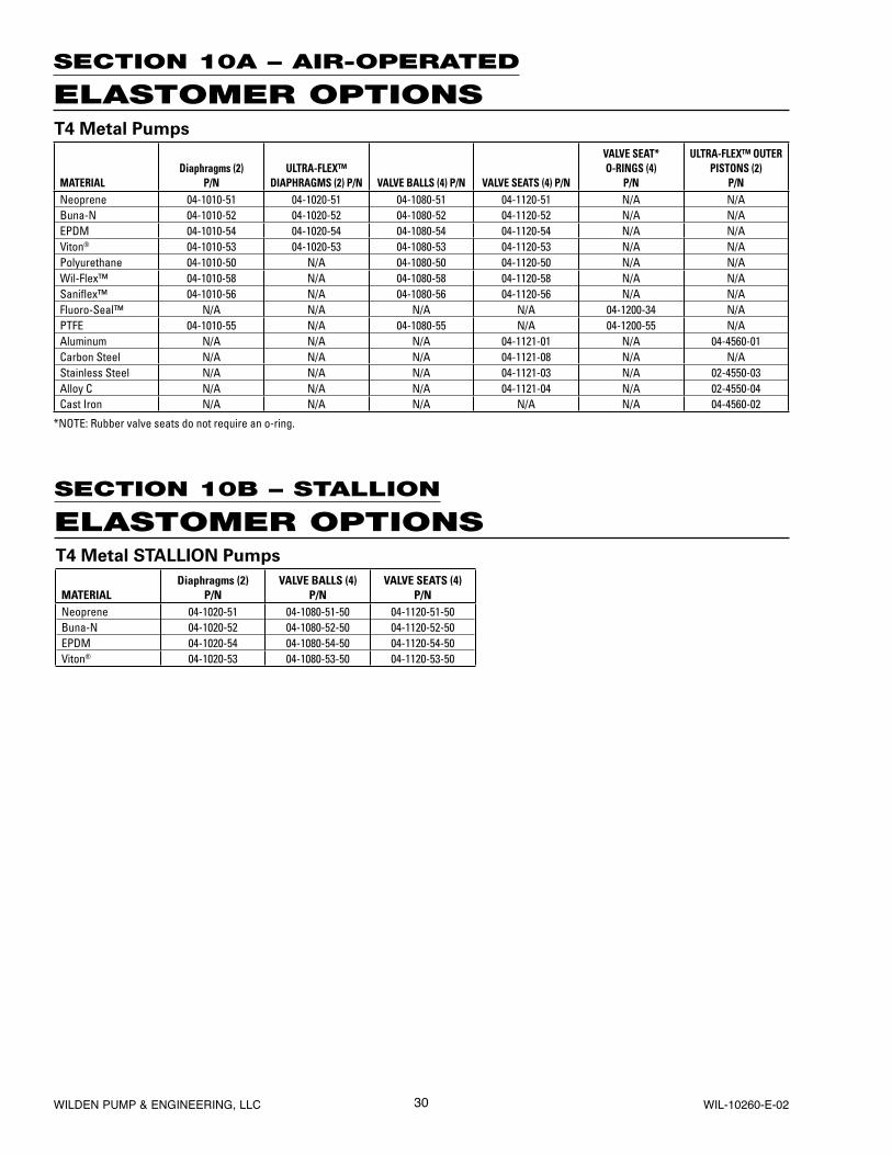
30WILDEN PUMP & ENGINEERING, LLC WIL-10260-E-02
SECTION 10A – AIR-OPERATED
ELASTOMER OPTIONS
SECTION 10B – STALLION
ELASTOMER OPTIONS
T4 Metal Pumps
MATERIALDiaphragms (2)
P/NULTRA-FLEX™
DIAPHRAGMS (2) P/N VALVE BALLS (4) P/N VALVE SEATS (4) P/N
VALVE SEAT* O-RINGS (4)
P/N
ULTRA-FLEX™ OUTER PISTONS (2)
P/NNeoprene 04-1010-51 04-1020-51 04-1080-51 04-1120-51 N/A N/ABuna-N 04-1010-52 04-1020-52 04-1080-52 04-1120-52 N/A N/AEPDM 04-1010-54 04-1020-54 04-1080-54 04-1120-54 N/A N/AViton® 04-1010-53 04-1020-53 04-1080-53 04-1120-53 N/A N/APolyurethane 04-1010-50 N/A 04-1080-50 04-1120-50 N/A N/AWil-Flex™ 04-1010-58 N/A 04-1080-58 04-1120-58 N/A N/ASanifl ex™ 04-1010-56 N/A 04-1080-56 04-1120-56 N/A N/AFluoro-Seal™ N/A N/A N/A N/A 04-1200-34 N/APTFE 04-1010-55 N/A 04-1080-55 N/A 04-1200-55 N/AAluminum N/A N/A N/A 04-1121-01 N/A 04-4560-01Carbon Steel N/A N/A N/A 04-1121-08 N/A N/AStainless Steel N/A N/A N/A 04-1121-03 N/A 02-4550-03Alloy C N/A N/A N/A 04-1121-04 N/A 02-4550-04Cast Iron N/A N/A N/A N/A N/A 04-4560-02
*NOTE: Rubber valve seats do not require an o-ring.
T4 Metal STALLION Pumps
MATERIALDiaphragms (2)
P/NVALVE BALLS (4)
P/NVALVE SEATS (4)
P/NNeoprene 04-1020-51 04-1080-51-50 04-1120-51-50Buna-N 04-1020-52 04-1080-52-50 04-1120-52-50EPDM 04-1020-54 04-1080-54-50 04-1120-54-50Viton® 04-1020-53 04-1080-53-50 04-1120-53-50
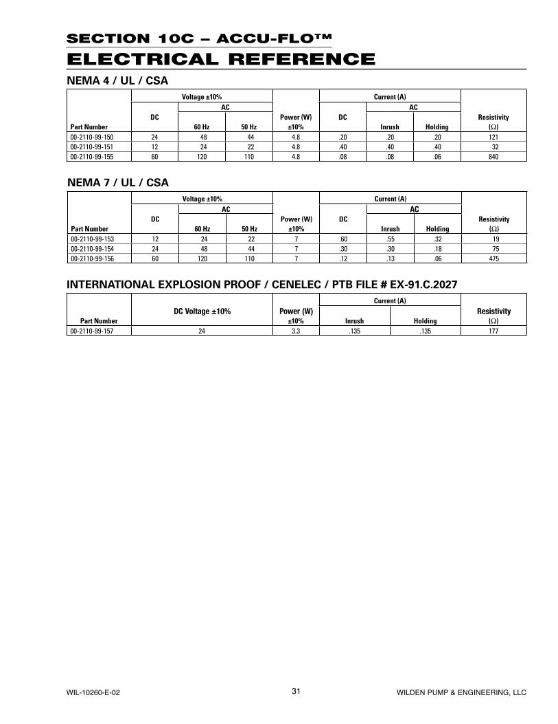
31 WILDEN PUMP & ENGINEERING, LLCWIL-10260-E-02
SECTION 10C – ACCU-FLO™
ELECTRICAL REFERENCENEMA 4 / UL / CSA
Voltage ±10% Current (A)AC AC
DC Power (W) DC ResistivityPart Number 60 Hz 50 Hz ±10% Inrush Holding (Ω)00-2110-99-150 24 48 44 4.8 .20 .20 .20 12100-2110-99-151 12 24 22 4.8 .40 .40 .40 3200-2110-99-155 60 120 110 4.8 .08 .08 .06 840
NEMA 7 / UL / CSA
Voltage ±10% Current (A)AC AC
DC Power (W) DC ResistivityPart Number 60 Hz 50 Hz ±10% Inrush Holding (Ω)00-2110-99-153 12 24 22 7 .60 .55 .32 1900-2110-99-154 24 48 44 7 .30 .30 .18 7500-2110-99-156 60 120 110 7 .12 .13 .06 475
INTERNATIONAL EXPLOSION PROOF / CENELEC / PTB FILE # EX-91.C.2027
Current (A)DC Voltage ±10% Power (W) Resistivity
Part Number ±10% Inrush Holding (Ω)00-2110-99-157 24 3.3 .135 .135 177
32WILDEN PUMP & ENGINEERING, LLC WIL-10260-E-02
Item # Serial #
Company Where Purchased
Company Name
Industry
Name Title
Street Address
City State Postal Code Country
Telephone Fax E-mail Web Address
Number of pumps in facility? Number of Wilden pumps?
Types of pumps in facility (check all that apply): Diaphragm Centrifugal Gear Submersible Lobe
Other
Media being pumped?
How did you hear of Wilden Pump? Trade Journal Trade Show Internet/E-mail Distributor
Other
P U M P I N F O R M AT I O N
PLEASE PRINT OR TYPE AND FAX TO WILDEN
YO U R I N F O R M AT I O N
ONCE COMPLETE, FAX TO (909) 783-3440
NOTE: WARRANTY VOID IF PAGE IS NOT FAXED TO WILDEN
WILDEN PUMP & ENGINEERING, LLC
W A R R A N T YEach and every product manufactured by Wilden Pump and Engineering, LLC is built to meet the highest standards of quality. Every pump is functionally tested to insure integrity of operation.
Wilden Pump and Engineering, LLC warrants that pumps, accessories and parts manufactured or supplied by it to be free from defects in material and workmanship for a period of five (5) years from date of installation or six (6) years from date of manufacture, whichever comes first. Failure due to normal wear, misapplication, or abuse is, of course, excluded from this warranty.
Since the use of Wilden pumps and parts is beyond our control, we cannot guarantee the suitability of any pump or part for a particular application and Wilden Pump and Engineering, LLC shall not be liable for any consequential damage or expense arising from the use or misuse of its products on any application. Responsibility is limited solely to replacement or repair of defective Wilden pumps and parts.
All decisions as to the cause of failure are the sole determination of Wilden Pump and Engineering, LLC.
Prior approval must be obtained from Wilden for return of any items for warranty consideration and must be accompanied by the appropriate MSDS for the product(s) involved. A Return Goods Tag, obtained from an authorized Wilden distributor, must be included with the items which must be shipped freight prepaid.
The foregoing warranty is exclusive and in lieu of all other warranties expressed or implied (whether written or oral) including all implied warranties of merchantability and fitness for any particular purpose. No distributor or other person is authorized to assume any liability or obligation for Wilden Pump and Engineering, LLC other than expressly provided herein.