T1 ESF CSU - verilink.com · services on a standard 10-workday-turnaround basis. Safety ... •...
24
T1 ESF CSU Reference Manual May 2002 34-00309.B
Transcript of T1 ESF CSU - verilink.com · services on a standard 10-workday-turnaround basis. Safety ... •...

T1 ESF CSUReference Manual
May 200234-00309.B
Copyright Notice Copyright © 2002 Verilink Corporation. All rights reserved. No part of this publication may be reproduced, transmitted, transcribed, stored in a retrieval system, or translated into any language in any form by any means without the written permission of Verilink.
Manual Reorder # 34-00309.B
May 2002
Trademarks Verilink® is a registered trademark of the Verilink Corporation.
All other brand and product names used herein are trademarks or registered trademarks of their respective manufacturers.
Documentation Disclaimer
This document does not create any express or implied warranty about Verilink or about its products or services. Verilink’s sole warranty is contained in its product warranty. The end-user documentation is shipped with Verilink’s products and constitutes the sole specifications referred to in the product warranty. Verilink has made reasonable efforts to verify that the information contained herein is accurate, but Verilink assumes no responsibility for its use or for any infringement of patents or other rights of third parties that may result. The customer is solely responsible for verifying the suitability of Verilink’s products for its use. Specifications are subject to change without notice.
FCC Requirements This equipment has been tested and found to comply with the limits for a Class A digital device, pursuant to Part 15 of FCC Rules. These limits are designed to provide reasonable protection against harmful interference when the equipment is operated in a commercial environment. This equipment generates, uses, and can radiate radio frequency energy and if not installed and used in accordance with the instruction manual, may cause harmful interference to radio communications. Operation of this equipment in a residential area is likely to cause harmful interference in which case the user is required to correct the interference at his own expense. This device must also accept any interference received, including interference that may cause undesired operation. Shielded cables must be used to ensure compliance with the Class A FCC limits.
WARNING: For use only with a certified Class 2 power supply. See "Power Source" in Specifications on page 2.
WARNING: Changes or modifications to this unit not expressly approved by the party responsible for compliance could void the user’s authority to operate the equipment.
This device complies with Part 15 of the FCC rules. Operation is subject to the following two conditions:
1 This device may not cause harmful interference.
2 This device must accept any interference received, including interference that may cause undesired operation.
This equipment complies with Part 68 of the FCC Rules. On the rear or bottom of the unit is a label that contains the FCC registration number and other information. If requested, provide this information to the telephone company.
ii

Notice to Usersof 1.544 Mbps
Service
The following instructions are provided to ensure compliance with FCC Rules, Part 68.
1 All direct connections to the network lines must be made using standard plugs and jacks (compliant with Part 68). The table below presents a list of applicable registration jack USOCs, facility interface codes (FICs), and service order codes (SOCs). This information may be required by the local telephone company when applying for leased line facilities.
2 If the unit appears to be malfunctioning, it should be disconnected from the network lines until the source of trouble is determined to be your equipment or the telephone line. If your equipment needs repair, it should not be reconnected until it is repaired.
3 The unit has been designed to prevent harm to the network. If the telephone company finds that the equipment is exceeding tolerable parameters, it can temporarily disconnect service. In this case, the telephone company will give you advance notice, if possible.
4 Under FCC rules, no customer is authorized to repair this equipment. This restriction applies regardless of whether the equipment is in or out of warranty.
5 If the telephone company alters its equipment in a manner that will affect the use of this device, it must give you warning so that you have the opportunity for uninterrupted service. You will be advised of your right to file a complaint with the FCC.
6 If the equipment malfunctions, all repairs should be performed by our company or an authorized agent. It is the responsibility of users requiring service to report the need for service to our company or to one of our authorized agents.
7 The affidavit at the end of this manual must be completed by the installer.
Canadian Emissions Requirements
This digital apparatus does not exceed the Class A limits for radio noise emissions from digital apparatus set out in the Radio Interference Regulations of the Canadian Department of Communications.
Le présent appareil numérique n’émet pas de bruits radioélectriques dépassant les limites applicables aux appareils numériques (de la class A) prescrites dans le Règlement sur le brouillage radioélectrique édicté par le ministère des Communications du Canada.
WARNING:For use only with a certified Class 2 power supply. See Power Source in Specifications on page 2.
WARNING:Changes or modifications to this unit not expressly approved by the party responsible for compliance could void the user’s authority to operate the equipment.
Notice: The Industry Canada label identifies certified equipment. This certification means that the equipment meets certain telecommunications
Port ID REN/SOC FIC USOC
1.544 Mbps SF1.544 Mbps SF, B8ZS1.544 Mbps ANSI ESF1.544 Mbps ANSI ESF, B8ZS
6.0F 04DU9-BN 04DU9-DN 04DU9-1KN04DU9-1SN
RJ-48C jack
iii
network protective, operational and safety requirements. The Industry Canada does not guarantee the equipment will operate to the user’s satisfaction.
Before installing this equipment, users should ensure that it is permissible to be connected to the facilities of the local telecommunications company. The equipment must also be installed using an acceptable method of connection. In some cases, the company’s inside wiring associated with a single line individual service may be extended by means of a certified connector assembly (telephone extension cord). The customer should be aware that compliance with the above conditions may not prevent degradation of service in some situations.
Repairs to certified equipment should be made by an authorized Canadian maintenance facility designated by the supplier. Any repairs or alterations made by the user to this equipment, or equipment malfunctions, may give the telecommunications company cause to request the user to disconnect the equipment.
Users should ensure for their own protection that the electrical ground connections of the power utility, telephone lines and internal metallic water pipe system, if present, are connected together. This precaution may be particularly important in rural areas.
Caution: Users should not attempt to make such connections themselves, but should contact the appropriate electric inspection authority, or electrician, as appropriate.
Warranty Verilink's product warranty covers repair or replacement of all equipment under normal use for a five-year period from date of shipment. Replacement products may be new or reconditioned. Any replaced or repaired product or part has a ninety (90) day warranty or the remainder of the initial warranty period, whichever is longer. Our in-house Repair Center services on a standard 10-workday-turnaround basis.
Safety Precautions
When handling this equipment, follow these basic safety precautions to reduce the risk of electric shock and injury:
• Follow all warnings and instructions marked on the product and in the manual.
• Unplug the hardware from the wall outlet before cleaning. Do not use liquid cleaners or aerosol cleaners. Use a slightly damp cloth for cleaning.
• Do not place this product on an unstable cart, stand, or table. It may fall, causing serious damage to the product.
• This product should be operated only from the type of power source indicated on the marking label and manual. If you are unsure of the type of power supply you are using, consult your dealer or local power company.
• Do not allow anything to rest on the power cord. Do not locate this product where the cord will interfere with the free movement of people.
• Do not overload wall outlets and extension cords, as this can result in fire or electric shock.
• Never push objects of any kind into the unit. They may touch dangerous voltage points or short out parts that could result in fire or electric shock. Never spill liquid of any kind on this equipment.
iv

• Unplug the equipment from the wall outlet and refer servicing to qualified service personnel under the following conditions:
• When the power supply cord or plug is damaged or frayed.
• If liquid has been spilled into the product.
• If the product has been exposed to rain or water.
• If the product has been dropped or if the housing has been damaged.
v

vi
Table of Contents About the T1 ESF CSUAbout this Manual . . . . . . . . . . . . . . . . . . . . . . . . . . . . . . . . . . . . . . . . . . . . . . . . . . . . .ix
Manual Organization . . . . . . . . . . . . . . . . . . . . . . . . . . . . . . . . . . . . . . . . . . . . . . . .ixTypographic Conventions . . . . . . . . . . . . . . . . . . . . . . . . . . . . . . . . . . . . . . . . . . . . .ix
Customer Service and Technical Support . . . . . . . . . . . . . . . . . . . . . . . . . . . . . . . . . . . xSupport from Your Network Supplier . . . . . . . . . . . . . . . . . . . . . . . . . . . . . . . . . . . xSupport from Verilink . . . . . . . . . . . . . . . . . . . . . . . . . . . . . . . . . . . . . . . . . . . . . . . . x
Returning a Unit to Verilink . . . . . . . . . . . . . . . . . . . . . . . . . . . . . . . . . . . . . . . . . . . . . .xi
1 General InformationIntroduction . . . . . . . . . . . . . . . . . . . . . . . . . . . . . . . . . . . . . . . . . . . . . . . . . . . . . . . . . . 1Features . . . . . . . . . . . . . . . . . . . . . . . . . . . . . . . . . . . . . . . . . . . . . . . . . . . . . . . . . . . . . 1Specifications . . . . . . . . . . . . . . . . . . . . . . . . . . . . . . . . . . . . . . . . . . . . . . . . . . . . . . . . . 2
Network Interface . . . . . . . . . . . . . . . . . . . . . . . . . . . . . . . . . . . . . . . . . . . . . . . . . . 2Equipment Interface . . . . . . . . . . . . . . . . . . . . . . . . . . . . . . . . . . . . . . . . . . . . . . . . 2Mechanical . . . . . . . . . . . . . . . . . . . . . . . . . . . . . . . . . . . . . . . . . . . . . . . . . . . . . . . . 2Power Source . . . . . . . . . . . . . . . . . . . . . . . . . . . . . . . . . . . . . . . . . . . . . . . . . . . . . . 2Industry Standards . . . . . . . . . . . . . . . . . . . . . . . . . . . . . . . . . . . . . . . . . . . . . . . . . . 2Environmental . . . . . . . . . . . . . . . . . . . . . . . . . . . . . . . . . . . . . . . . . . . . . . . . . . . . . 2
2 Installation and ConfigurationIntroduction . . . . . . . . . . . . . . . . . . . . . . . . . . . . . . . . . . . . . . . . . . . . . . . . . . . . . . . . . . 3Safety Summary . . . . . . . . . . . . . . . . . . . . . . . . . . . . . . . . . . . . . . . . . . . . . . . . . . . . . . . 3Unpacking and Inspection . . . . . . . . . . . . . . . . . . . . . . . . . . . . . . . . . . . . . . . . . . . . . . . 3Supplied Materials . . . . . . . . . . . . . . . . . . . . . . . . . . . . . . . . . . . . . . . . . . . . . . . . . . . . . 3Wall-mount Installation . . . . . . . . . . . . . . . . . . . . . . . . . . . . . . . . . . . . . . . . . . . . . . . . . 4
Using Adhesive Strips . . . . . . . . . . . . . . . . . . . . . . . . . . . . . . . . . . . . . . . . . . . . . . . 4Using Screws . . . . . . . . . . . . . . . . . . . . . . . . . . . . . . . . . . . . . . . . . . . . . . . . . . . . . . 4
Connections . . . . . . . . . . . . . . . . . . . . . . . . . . . . . . . . . . . . . . . . . . . . . . . . . . . . . . . . . . 4Equipment and Network Connections . . . . . . . . . . . . . . . . . . . . . . . . . . . . . . . . . . 4Power Connection . . . . . . . . . . . . . . . . . . . . . . . . . . . . . . . . . . . . . . . . . . . . . . . . . . 5
Configuration . . . . . . . . . . . . . . . . . . . . . . . . . . . . . . . . . . . . . . . . . . . . . . . . . . . . . . . . . 5Configuration Switch SW1 . . . . . . . . . . . . . . . . . . . . . . . . . . . . . . . . . . . . . . . . . . . 5
3 TestingIntroduction . . . . . . . . . . . . . . . . . . . . . . . . . . . . . . . . . . . . . . . . . . . . . . . . . . . . . . . . . . 7Indicators . . . . . . . . . . . . . . . . . . . . . . . . . . . . . . . . . . . . . . . . . . . . . . . . . . . . . . . . . . . . 7Loopbacks . . . . . . . . . . . . . . . . . . . . . . . . . . . . . . . . . . . . . . . . . . . . . . . . . . . . . . . . . . . 7
Equipment . . . . . . . . . . . . . . . . . . . . . . . . . . . . . . . . . . . . . . . . . . . . . . . . . . . . . . . . . 7Network . . . . . . . . . . . . . . . . . . . . . . . . . . . . . . . . . . . . . . . . . . . . . . . . . . . . . . . . . . 8
Test Jacks . . . . . . . . . . . . . . . . . . . . . . . . . . . . . . . . . . . . . . . . . . . . . . . . . . . . . . . . . . . . 9
Affidavit for the Connection of Customer Premises Equipment to 1.544 Mbps and /or Subrate Digital Services
vii

viii

ABOU
T THE T1 ESF CSUAbout this ManualThis is a reference manual. It provides information about unit installation, configuration and testing. It is not a user’s guide containing step-by-step procedures. This manual is designed to be used when you need specific information about a command, interface port, configuration parameter, etc. Unless otherwise noted, the information in this manual applies only to the Verilink T1 ESF CSU (also referred to as the unit.)
Manual Organization
The chapters and appendices in this manual are arranged for quick reference when you need it. You do not have to read previous chapters to understand the subsequent chapters.
Chapter 1, "General Information" -- This chapter introduces the unit, lists the features, and provides specifications.
Chapter 2, "Installation and Configuration" -- This chapter describes unit installation, port and power connections, and switch settings.
Chapter 3, "Testing" -- This chapter describes the indicators, test switch, loopbacks, and test jacks.
“Affidavit for the Connection of Customer Premises Equipment to 1.544 Mbps and /or Subrate Digital Services” -- Appended to the end of this manual, this affidavit may be required by your telco.
Typographic Conventions
The following table lists the conventions that are used throughout this guide.
Convention Description
A Notice calls attentions to important features or instructions.
A Caution alerts you to serious risk of data loss or other results that may cause you or the unit trouble if the warning is not heeded.
About this Manual ix

Customer Service and Technical SupportVerilink provides easy access to customer support information through a variety of services. This section describes these services.
Support from Your Network Supplier
If assistance is required, contact your network supplier. Many suppliers are authorized Verilink service partners who are qualified to provide a variety of services, including network planning, installation, hardware maintenance, application training, and support services. When you contact your network supplier for assistance, have the following information ready:
Diagnostic error messages
A list of system hardware and software, including revision levels
Details about recent configuration changes, if applicable
Support from Verilink
If you are unable to receive support from your network supplier or want to contact us directly, Verilink offers worldwide customer support by telephone, e-mail, and through Verilink’s Internet Web site.
TelephoneCustomer support is available by telephone 24 hours a day, 7 days a week. To speak directly with a Verilink customer service representative, you may dial one of the following numbers:
Sales and Marketing:800-VERILINK (837-4546)
Technical Support: 800-285-2755 (toll-free)
E-mailYou can request sales and marketing information or pose a technical support question about your Verilink product by
A Warning alerts you to the risk of serious damage to the unit or injury and possible death to the end user.
“Enter” vs. “Type”
When the word enter is used in this guide, it means type something, then press the Return or Enter key. Do not press the Return or Enter key when an instruction simply says type.
Italics Refers you to other sections of this manual.
Convention Description
x ABOUT THE T1 ESF CSU

contacting us at the e-mail addresses provided below. Verilink will respond to e-mailed requests for support during regular business hours (8–5 CST, Monday–Friday).
Sales and Marketing: [email protected]
Technical Support: [email protected]
InternetAccess the latest networking information on Verilink’s Internet Web site by entering our URL into your Internet browser:
http://www.verilink.com/
This service features information about Verilink products, customer service, technical support, latest news releases, and more.
Returning a Unit to VerilinkIf for any reason you must return your Verilink product, it must be returned to the factory, shipping prepaid and packaged to the best commercial standard for electronic equipment. Verilink will pay shipping charges for delivery on return. You are responsible for mode and cost of shipment to Verilink.
You must have a Return Material Authorization (RMA) number marked on the shipping package. Products sent to Verilink without RMA numbers will be returned to the sender unopened, at the sender’s expense.
A product sent directly to Verilink for repair must first be assigned a Return Materials Authorization (RMA) number. You may obtain an RMA number by calling Customer Service at 800-VERILINK, extension 3002. Customer Service will also give you a shipping address.
When calling for an RMA, please have the following information available:
Model number and serial number for each unit
Reason for return and symptoms of problem
Warranty status (if known)
Purchase order number to cover charges for out-of-warranty items
Name and phone number of person we can contact if we have questions about the unit(s)
Returning a Unit to Verilink xi

Mode of shipment required (second-day air is the normal mode of shipment for all returned material unless otherwise specified).
xii ABOUT THE T1 ESF CSU

1
GENERAL INFORMATIONIntroductionVerilink’s T1 ESF CSU provides an economical solution for providing the T1 interface between customer premises equipment and T1 facilities (telco or private). Each unit is compatible with all T1 carrier transmission equipment and is designed to comply with all industry-standard specifications. Both the transmitted and received 1.544 Mbps signals are conditioned.
The T1 ESF CSU is an industry standard T1 channel service unit. It detects and activates network initiated loopbacks, monitors bipolar violations, and maintains pulse density of the transmitted signal. The unit is capable of interfacing to both B8ZS and AMI circuits and can convert signal formats or line coding to integrate older equipment. Automatic transmission of ESF performance report messages (PRM) is also supported by the T1 ESF CSU.
The unit is designed to be wallmounted using hook-and-loop fasteners or “T” openings on the base (like a telephone). The unit can also be set on a desktop.
The unit provides ALBO circuitry on the network receive path. The network ALBO supports a receive range from +1 to −30 decibels. The DTE supports DSX1 signal ranges up to 655 feet. The unit also provides line build out (LBO) circuitry on both network and DTE. The network transmit LBO is user selectable in four increments (from 0 to −22.5 decibels). The DTE transmit LBO is user selectable in five increments from 0 to 655 feet.
The T1 ESF CSU operates from an external power source. Network and DTE connections are made through RJ-48C connectors. The units have primary and secondary surge protection on both the network and DTE side (meeting the UL 1950 requirements).
Features Provides T1 facility interface and jitter tolerance per ANSI
T1.102, T1.403, and AT&T TR 62411
Supports B8ZS or AMI formats
Conversion for signal formats and line coding
Supports PRM in ESF mode
Space-saving design can be desktop or wall mounted
Standard 5-year warranty
Introduction 1

SpecificationsNetwork Interface
Line Rate: 1.544 Mbps (± 50 ppm)
Line Framing: D4 or ESF
Line Code: AMI or B8ZS
Line Impedance: balanced 100 Ω (± 5%)
Input Signal: DS1, +1 to -30 dB (ALBO)
Output Signal: 3.0 V, ±15%, base-peak into 100 Ω
Line Build Out: 0, −7.5, −15, and −22.5 dB attenuation
Line Protection: 1000 V lightning, fused input and output
Jitter Control: per TR 62411 and T1.403
Pulse Density: per TR 62411
Equipment Interface
Line Rate: 1.544 Mbps (± 50 ppm)
Line Framing: D4 or ESF
Line Code: AMI or B8ZS
Line Impedance: balanced 100 Ω (± 5%)
Input Signal: DSX1 to 655 feet
Output Signal: Selectable DSX1 signal level from 0 to 655 feet
Line Protection: 1000 V lightning, input and output
Mechanical
Mounting: desktop or wallmount
Dimensions: 1.25" H, 3.5" W, 5.75" D
Weight: 1 pound
Power Source
External: Input: 115 VACOutput: 9 VDC, 1.2 A
Industry Standards
FCC Compliance: Part 15 Class A Subpart B, Part 68
Safety: UL 60950
Industry Canada: CS-03, Issue 8
Environmental
Operating Temp: 0° to 50°C (32° to 122°F)
Storage Temp: −20° to 70°C (−4° to 158°F)
Humidity: 95% max (non-condensing)
2 GENERAL INFORMATION
2
INSTALLATION AND CONFIGURATIONIntroductionThis chapter contains information and instructions required to prepare Verilink’s T1 ESF CSU for use. Included are initial inspection procedures, mounting instructions, configuration guidelines, connection and powering information.
Safety SummaryThis manual contains information and warnings that must be followed to ensure safe operation and retain the equipment in a safe condition.
This WARNING sign denotes a potential hazard to the operator. It calls attention to a procedure or practice that, if not correctly performed or adhered to, could result in injury or loss of life. Do not proceed beyond a WARNING sign until the indicated conditions are fully understood and met.
Units are susceptible to damage caused by static electricity. Use ESD (electrostatic discharge) precautionary measures, such as wearing electrostatic grounding straps.
Unpacking and InspectionThis unit is carefully packaged to prevent damage in shipment. Upon receipt, inspect the shipping container for damage. If the shipping container or cushioning material is damaged, notify the carrier immediately and make a notation on the delivery receipt that the container was damaged (if possible, obtain the signature and name of the person making delivery). Retain the packaging material until verifying the contents of the shipment are complete and the unit has been checked both mechanically and electrically.
If the contents of the shipment are incomplete or, if there is mechanical damage or defect, notify Verilink. If the shipping container is also damaged, or the cushioning material shows signs of stress, notify the carrier of the damage as well as Verilink. Keep the shipping materials for the carrier’s inspection. Verilink will arrange for repair or replacement without waiting for claim settlement.
Supplied MaterialsThe T1 ESF CSU is shipped from the factory with the following standard equipment:
Introduction 3

external DC power supply
reference manual
adhesive strips
two 9-foot RJ48-to-RJ48 cables (part number 9-1544-619-009)
Wall-mount Installation
Using Adhesive Strips
1 Select a place close to an 115 VAC outlet with clearance for the signal and power cables as well as for bantam test cables. The indicators and switches should be easily accessible.
2 Verify the mounting surface is clean.
3 Cut the adhesive strip to the desired length and affix the backing of one piece to the underside of the unit.
4 Attach the other adhesive strip to the piece on the underside of the unit.
5 Remove the backing to expose the sticky surface.
6 Press the underside of the unit firmly against the selected place.
Using Screws
1 Select a place close to an 115 VAC outlet with clearance for the signal and power cables as well as for bantam test cables. The indicators and switches should be easily accessible.
2 Vertically place two #6 screws 3-13 ⁄ 32 inches apart at the selected place. Leave the screws out about an eighth of an inch.
3 Place the upright unit over the screws until the holes engage and slide the unit down until it locks.
ConnectionsThe T1 ESF CSU has RJ-48C connectors for the network and equipment interfaces and a terminal strip for the power connection. The following paragraphs describe these connections.
Equipment and Network Connections
Table 2-1 shows the pinout for the network and equipment connectors. The interface for these connectors is an RJ-48C jack.
Table 2-1 Pinout for Network/Equipment Connectors
Pin NET Equipment1 R1 (ring, receive from network) R1 (ring, transmit to equipment)
2 T1 (tip, receive from network) T1 (tip, transmit to equipment)
4 R (ring, transmit to network) R (ring, receive from network)
5 T (tip, transmit to network) T (tip, receive from network)
3, 6–8 not used not used
4 INSTALLATION AND CONFIGURATION
Power Connection
Plug the connector from the power supply into the unit. Plug the transformer into an appropriate grounded outlet. This will apply power to the unit.
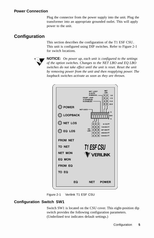
ConfigurationThis section describes the configuration of the T1 ESF CSU. This unit is configured using DIP switches. Refer to Figure 2-1 for switch locations.
NOTICE: On power up, each unit is configured to the settings of the option switches. Changes to the NET LBO and EQ LBO switches do not take effect until the unit is reset. Reset the unit by removing power from the unit and then reapplying power. The loopback switches activate as soon as they are thrown.
Figure 2-1 Verilink T1 ESF CSU
Configuration Switch SW1
Switch SW1 is located on the CSU cover. This eight-position dip switch provides the following configuration parameters. (Underlined text indicates default settings.)
Configuration 5

NOTICE: Position SW1-1 is not enabled for use.
E Q L B O Positions SW1-2, SW1-3, and SW1-4 set the EQ LBO (line build out) transmit signal value towards the customer equipment. The value should match the cable length from the EQ port to the attached equipment. The default is 0 to 133 feet (AAA).
E qu ipm ent L oop Position SW1-5 sets equipment loopback functions. When the switch is set to Enabled (B), the unit is placed into an equipment loopback where the equipment receives all the data it sends. The unit remains in equipment loopback until the switch is set to Disabled (A). The unit sends an unframed all ones pattern to the network.
N etw ork L oop Position SW1-6 sets network loopback functions. NET LOOP can be set to Auto or Manual. Auto (A) enables the unit to respond to network loop requests. Setting the switch to Manual (B) forces the unit into a manual network loopback. During loop, the unit sends an unframed all ones pattern to the equipment. It responds to inband CSU loop (1-in-5 pattern) and unloop (1-in-3 pattern), ESF out-of-band line loopback/payload loopback, and loop up/loop down codes, and responds to the universal loopdown code even if the switch is in the "Manual" position.
N etw ork L B O Positions SW1-7 and SW1-8 set the network line build out signal level transmitted towards the T1 facility. The default output level is 0 dB (AA). Change the signal level to -7.5 dB, -15 dB, or -22.5 dB as necessary. The telco can provide the proper setting. If unsure of the setting, leave it at 0 dB.
6 INSTALLATION AND CONFIGURATION

3
TESTINGIntroduction 7
IntroductionThis chapter describes the diagnostic and test features of Verilink’s T1 ESF CSU. The unit is controlled manually using front panel DIP switches (the DIP switches are discussed on page 5). The front panel indicators and side bantam jacks are described below.
IndicatorsThe unit indicators convey major alarm conditions and looping status.
POWER This green indicator lights when power is applied to the unit.
LOOPBACK This amber indicator lights under the following conditions: the NET LOOP switch is set to Manual; the EQUIP LOOP is placed in the Enabled position; or the unit receives an inband (or out-of-band) loop code from the network.
NET LOS This red indicator lights if the internal alarm circuitry detects a loss of signal condition for ≥ 175 bit times or if it detects an unframed error from the network. The indicator stays lit until the unit detects ≥ 4 pulses in 32 bit times.
EQ LOS This red indicator lights if the internal alarm circuitry detects a loss of signal condition for ≥ 175 bit times or if it detects an unframed error from the DTE. The indicator stays lit until the unit detects ≥ 4 pulses in 32 bit times.
Loopbacks
Equipment
Position SW1-5 sets equipment loopback functions. When the switch is set to Enabled, the unit is placed into an equipment loopback where the DTE receives all the data it sends. The unit sends an unframed all ones pattern to the network end. The unit remains in equipment loopback until the switch is set to Disabled.
Figure 3-1 Local Loopback
EquipmentT1 ESF CSU
NetworkAIS
Network
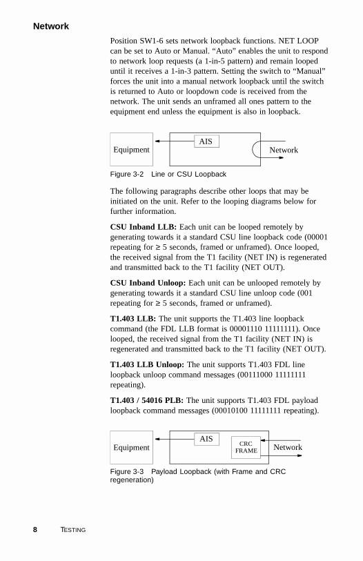
Position SW1-6 sets network loopback functions. NET LOOP can be set to Auto or Manual. “Auto” enables the unit to respond to network loop requests (a 1-in-5 pattern) and remain looped until it receives a 1-in-3 pattern. Setting the switch to “Manual” forces the unit into a manual network loopback until the switch is returned to Auto or loopdown code is received from the network. The unit sends an unframed all ones pattern to the equipment end unless the equipment is also in loopback.
Figure 3-2 Line or CSU Loopback
The following paragraphs describe other loops that may be initiated on the unit. Refer to the looping diagrams below for further information.
CSU Inband LLB: Each unit can be looped remotely by generating towards it a standard CSU line loopback code (00001 repeating for ≥ 5 seconds, framed or unframed). Once looped, the received signal from the T1 facility (NET IN) is regenerated and transmitted back to the T1 facility (NET OUT).
CSU Inband Unloop: Each unit can be unlooped remotely by generating towards it a standard CSU line unloop code (001 repeating for ≥ 5 seconds, framed or unframed).
T1.403 LLB: The unit supports the T1.403 line loopback command (the FDL LLB format is 00001110 11111111). Once looped, the received signal from the T1 facility (NET IN) is regenerated and transmitted back to the T1 facility (NET OUT).
T1.403 LLB Unloop: The unit supports T1.403 FDL line loopback unloop command messages (00111000 11111111 repeating).
T1.403 / 54016 PLB: The unit supports T1.403 FDL payload loopback command messages (00010100 11111111 repeating).
Figure 3-3 Payload Loopback (with Frame and CRC regeneration)
Equipment NetworkAIS
Equipment NetworkAIS
CRCFRAME
8 TESTING

T1.403 / 54016 PLB Unloop: The unit supports T1.403 FDL payload loopback unloop command messages (00110010 11111111 repeating).
Test JacksThe bantam jacks located on the left side of the unit provide signal access as follows:
The FROM NET and TO NET jacks can be used to break the network connection to the T1 ESF CSU internal circuitry and connect the network to a piece of test equipment.
The NET MON and EQ MON jacks are used for passively monitoring received signals passing through the unit (between the DTE and the network).
The FROM EQ and TO EQ jacks can be used to break the equipment connection to the T1 ESF CSU internal circuitry and connect the equipment to a piece of test equipment
NOTICE: When connected to the TO EQ and FROM EQ jacks, the EQ LOS indicator lights. This is due to the test connection and is not an indication of signal loss from the equipment.
Test Jacks 9

10 TESTING

AFFIDAVIT FOR THE CONNECTION OF CUSTOMER PREMISES EQUIPMENT TO 1.544 MBPS AND /OR SUBRATE DIGITAL SERVICES For work to be performed in the certified territory of
Telco’s Name: __________________________________________________________
State of __________________________________________________________
County of __________________________________________________________
I, ________________________________, of _________________________________,
(Authorized Representative Name) (Customer Name)
________________________________________, ____________________________,
(Customer Address) (Telephone Number)
being duly sworn, state:
I have responsibility for the operation and maintenance of the terminal equipment to be connected to ______________________ 1.544 Mbps and/or ___________________ subrate digital services. The terminal equipment to be connected complies with Part 68 of the Commission’s rules except for the encoded analog content, and billing protection specifications. With respect to encoded analog content and billing protection:
I attest that all operations associated with the establishment, maintenance, and adjustment of the digital CPE with respect to encoded analog content and encoded billing information continuously complies with Part 68 of the FCC’s Rules and Regulations.
The digital CPE does not transmit digital signals containing encoded analog content or billing information which is intended to be decoded within the telecommunications network.
The encoded analog and billing protection is factory set and is not under the control of the customer.
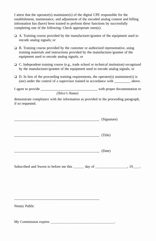
I attest that the operator(s) maintainer(s) of the digital CPE responsible for the establishment, maintenance, and adjustment of the encoded analog content and billing information has (have) been trained to perform these functions by successfully completing one of the following: Check appropriate ones(s).
A. Training course provided by the manufacturer/grantee of the equipment used to encode analog signals; or
B. Training course provided by the customer or authorized representative, using training materials and instructions provided by the manufacturer/grantee of the equipment used to encode analog signals; or
C. Independent training course (e.g., trade school or technical institution) recognized by the manufacturer/grantee of the equipment used to encode analog signals; or
D. In lieu of the proceeding training requirements, the operator(s) maintainer(s) is (are) under the control of a supervisor trained in accordance with _________ above.
I agree to provide ________________________________ with proper documentation to (Telco’s Name)
demonstrate compliance with the information as provided in the proceeding paragraph, if so requested.
________________________________________________ (Signature)
________________________________________________ (Title)
________________________________________________ (Date)
Subscribed and Sworn to before me this ______ day of __________________, 19____.
________________________________________________
Notary Public
My Commission expires ____________________________________.