CSU-05HCAA CSU-07HCAA CSU-09HCAA CSU-12HCAA CSU-18HCAA CSU-21HCAA CSU-24HCAA CSU...
107
Installation and Maintenance Manual CSU-05HCAA CSU-07HCAA CSU-09HCAA CSU-12HCAA CSU-18HCAA CSU-21HCAA CSU-24HCAA CSU-09HHAA CSU-12HHAA CSU-18HHAA CSU-21HHAA CSU-24HHAA
Transcript of CSU-05HCAA CSU-07HCAA CSU-09HCAA CSU-12HCAA CSU-18HCAA CSU-21HCAA CSU-24HCAA CSU...
Installation and Maintenance Manual
CSU-05HCAA CSU-07HCAA
CSU-09HCAA CSU-12HCAA
CSU-18HCAA CSU-21HCAA
CSU-24HCAA
CSU-09HHAA CSU-12HHAA
CSU-18HHAA CSU-21HHAA
CSU-24HHAA
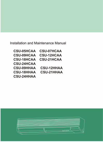
ContentI.Designations and Functions of parts
II. Dimensions
III.Specification............................
IV.Wiring diagram...............
V. Refrigeration circuit
VI.Installation Instruction........................................13
VII. Troubleshooting.
VIII.Parts list
1
I. Designations and functions of parts
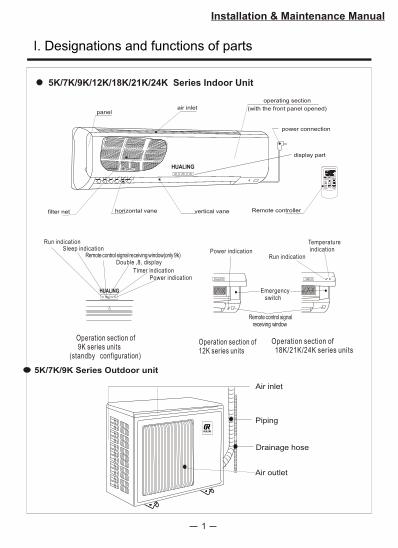
5K/7K/9K/12K/18K/21K/24K Series Indoor Unit
Installation & Maintenance Manual
panelair inlet
power connection
display part
filter net horizontal vane vertical vane
operating section
(with the front panel opened)
Remote controller
HUALING
Emergency switch
Operation section of 12K series units
Power indication
Remote control signalreceiving window
Run indication
Temperature indication
Operation section of 18K/21K/24K series units
Run indicationSleep indication
Timer indicationPower indication
Operation section of 9K series units
(standby configuration)
HUALING
Double ,8, display Remote control signal receiving window(only 9k)
Air inlet
Piping
Drainage hose
Air outlet
5K/7K/9K Series Outdoor unit
2
I. Designations and functions of parts
Installation & Maintenance Manual
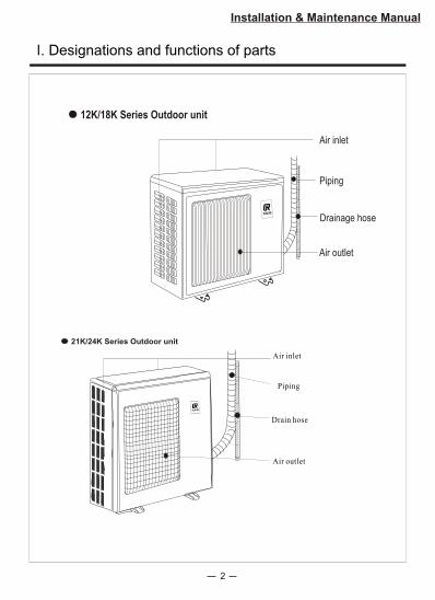
Air inlet
Piping
Drain hose
Air outlet
21K/24K Series Outdoor unit
Air inlet
Piping
Drainage hose
Air outlet
12K/18K Series Outdoor unit
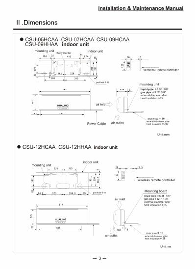
CSU-05HCAA CSU-07HCAA CSU-09HCAA
Power Cable
Unit:mm
liquid pipe 6.35 1/4Fgas pipe 9.52 3/8Fexternal diameter after heat insulation
Wireless Remote controller
•••
•••
•• •••
•••
Body Center
3
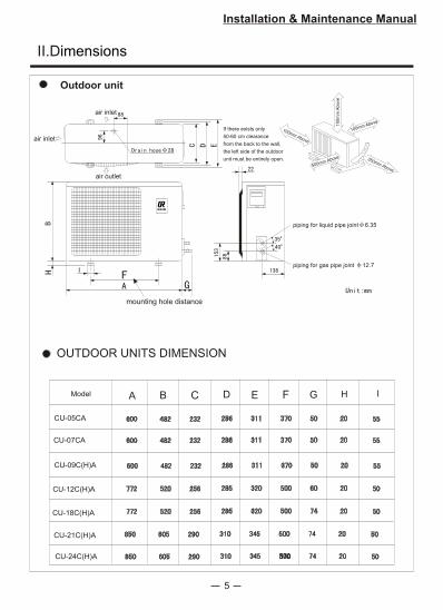
II .Dimensions
Installation & Maintenance Manual
mounting unit indoor unit
portholemounting unit
air inlet
air outlet
drain hoseexternal diameter after heat insulation 28
HUALING
CSU-09HHAA indoor unit
CSU-12HCAA CSU-12HHAA indoor unit
mounting unitindoor unit
Mounting board
liquid pipe 6.35 1/4Fgas pipe 12.7 1/2Fexternal diameter after heat insulation 35
air inlet
air outlet
wireless remote controller
drain hose
external diameter after heat insulation
porthole
Unit
HUALING
4
II.Dimensions
Installation & Maintenance Manual
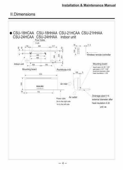
CSU-18HCAA CSU-18HHAA CSU-21HCAA CSU-21HHAA
190 5
liquid pipe 6.35 1/4Fgas pipe 12.7 1/2Fexternal diameter afterheat insulation 35
Four holes
Indoor unit
Mounting board Porthhole
Mounting board
Air inlet
Air outletDrainage pipe 16
external diameter after
heat insulation 28
Power cable
2m to the right side
1m to the left side
Wireless remote controller
unit
CSU-24HCAA CSU-24HHAA indoor unit
HUALING
5
II.Dimensions
Installation & Maintenance Manual
piping for liquid pipe joint 6.35
piping for gas pipe joint 12.7
air inlet
air inlet
air outlet
If there exists only
50-60 cm clearance
from the back to the wall,
the left side of the outdoor
unit must be entirely open.
100mm Above
100mm Above
10
0m
mA
bo
ve
500mm Above 350mm Above
mounting hole distance
Outdoor unit
CU-07CA
CU-12C(H)A
CU-09C(H)A
CU-18C(H)A
CU-21C(H)A
CU-24C(H)A
Model IHGFEDCBA
OUTDOOR UNITS DIMENSION
CU-05CA
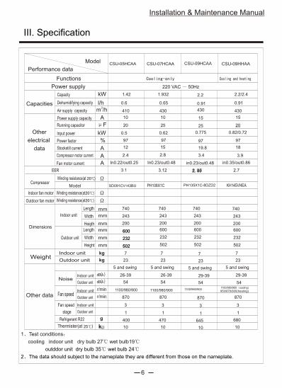
III. Specification
Installation & Maintenance Manual
6
kW
l/h3
m /h
A
F
A
A
A
%
mm
mm
mm
mm
mm
mm
1.42
0.6
410
10
97
kW
kg 7
23kg
dB A( )
dB A( )
r/min
r/min
3
1
g
k
7
23
5 and swing
3
1
97
15
740
243
200
600
232
502
20
0.5
12
2.4
In0.22/out0.25
SD091CV-H3BU
3.1
in0.35/out0.86
26-39
54
1100/980/900
870
470
10 10
680
950/870/800(heating)
870
29-39
1100/980/900 cooling)
2.2/2.4
0.91
430
0.82/0.72
20
18
KH145VHEA
3.9
2.7
Capacity
Performance data
Functions
Power supply
Model
Dehumidifying capacity
Air supply capacity
Power supply capacity
Running capacitor
Input power
Power factor
Stockstill current
Fan motor current
EER
Winding resistance(at )
Compressor motor current
Winding resistance(at )
Indoor unit
Outdoor unit
Length
Width
Heigth
Capacities
Other
electrical
data
Compressor
Indoor fan motor
Outdoor fan motor
Dimensions
Model
Winding resistance(at )
Length
Width
Height
Weight
Other data
Indoor unit
Outdoor unit
Noise
Indoor unit
Outdoor unit
Fan speed
Fan speed
stage
Refrigerant R22
Thermister(at )
Indoor unit
Outdoor unit
Indoor unit
Outdoor unit
1 Test conditions
cooling indoor unit dry bulb 27 wet bulb19
outddor unit dry bulb 35 wet bulb 24
2 The data should subject to the nameplate they are different from those on the nameplate.
5 and swing
CSU-09HCAACSU-05HCAA
220 VAC 50Hz
7
23
3
1
1.932
0.65
430
10
97
740
243
200
In0.23/out0.48
0.62
PH108X1C
25
15
2.8
3.12
26-39
54
870
10
5 and swing
7
23
3
1
2.2
0.91
430
15
97
0.775
25
19.8
3.4
29-39
54
870
645
10
5 and swing
in0.23/out0.48
PH135X1C-8DZD2
1100/980/9001100/980/900
CSU-09HHAACSU-07HCAA
400
54
600
232
502
600
232
502
600
232
502
740
243
200
600
232
502
740
243
200
Installation & Maintenance Manual
7
kW
l/h3
m /h
A
F
A
A
A
%
mm
mm
mm
mm
mm
mm
kW
kg
kg
dB A( )
dB A( )
r/min
r/min
g
k
8
35
3
3.1
1.27
490
5.4
97
740
200
243
772
254
540
in0.28/out0.56
1.15
PH215X2C-8FTC
35
29.9
5.55
2.68
35-41
54
780
10
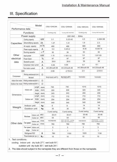
Cooling capacity
Performance data
Functions
Power supply
Model
Dehumidifying capacity
Air supply capacity
Power supply capacity
Running capacitor
Input power
Power factor
Stockstill current
Fan motor current
EER
Winding resistance(at )
Compressor motor current
Winding resistance(at )
Indoor unit
Outdoor unit
Length
Width
Heigth
Capacities
Other
electrical
data
Compressor
Indoor fan motor
Outdoor fan motor
Dimensions
Model
Winding resistance(at )
Length
Width
Height
Weight
Other data
Indoor unit
Outdoor unit
Noise
Indoor unit
Outdoor unit
Fan speed
Fan speed
stage
Refrigerant R22
Thermister(at )
Indoor unit
Outdoor unit
Indoor unit
Outdoor unit
1 Test conditions
cooling indoor unit dry bulb 27 wet bulb19
outddor unit dry bulb 35 wet bulb 24
2 The data should subject to the nameplate they are different from those on the nameplate.
5 and swing
CSU-12HCAA
220 VAC 50Hz
Cooling-only
8
35
3
1
3.2/3.42
1.31
490
5.4/5.2
97
772
254
540
in0.23/out0.48
1.16/1.13
PH215X2C-8FTC
35
29.9
5.55
2.75/3.0
35-41
54
1200/1120/1050 cooling)
1260/1160/1100(heating)
780
10
5 and swing
CSU-12HHAA
III. Specification
1100/980/900
1
780 1150
CSU-18HHAACSU-18HCAA
14
35
4.5
1.9
680
8.35
97
1015
320
200
772
254
540
in0.28/out0.56
1.8
50
39
8.1
2.5
35-46
55
5 and swing
14
35
4.48/4.98
2.3
680
8.35/7.6
97
1015
320
200
772
254
540
in0.23/out0.48
1.8/1.65
TH310VEEC
50
39
8.1
2.5/3.0
35-46
55
5 and swing
3
780
10
3
1
1050/980/900 cooling)
1050/1000/960(heating)
780
10
1050/980/900
1
1020 1130
740
200
243
TH310VEEC
Cooling-onlyCooling AND HEATING Cooling AND HEATING
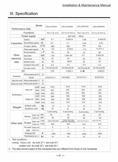
III. Specification
Installation & Maintenance Manual
8
kW
l/h3
m /h
A
F
A
A
A
%
mm
mm
mm
mm
mm
mm
5.1
2.0
680
8.9
97
kW
kg 14
47kg
dB A( )
dB A( )
r/min
r/min
3
1
g
k
14
53
5 and swing
3
1
97
11.4/11.4
850
290
610
50
1.92
42
9.3
in0.22/out0.25
SHW33TC4-U
2.65
in0.35/out0.86
46
59
1200/1120/1000
820
1300
10 10
1600
1280/1150/1050
910
46
5.94/6.63
2.43
730
2.38/2.38
50
52
SHV33YC6-G
11.5
2.48/2.8
Capacity
Performance data
Functions
Power supply
Model
Dehumidifying capacity
Air supply capacity
Power supply capacity
Running capacitor
Input power
Power factor
Stockstill current
Fan motor current
EER
Winding resistance(at )
Compressor motor current
Winding resistance(at )
Indoor unit
Outdoor unit
Length
Width
Heigth
Capacities
Other
electrical
data
Compressor
Indoor fan motor
Outdoor fan motor
Dimensions
Model
Winding resistance(at )
Length
Width
Height
Weight
Other data
Indoor unit
Outdoor unit
Noise
Indoor unit
Outdoor unit
Fan speed
Fan speed
stage
Refrigerant R22
Thermister(at )
Indoor unit
Outdoor unit
Indoor unit
Outdoor unit
1 Test conditions
cooling indoor unit dry bulb 27 wet bulb19
outddor unit dry bulb 35 wet bulb 24
2 The data should subject to the nameplate they are different from those on the nameplate.
5 and swing
CSU-24HCAACSU-21HCAA
220 VAC 50Hz
3
1
5.08/5.8
2.1
680
8.7/8.5
97
In0.23/out0.48
1.96/1.85
TH310VEEC
50
38/42
8.1
2.58/3.1
46
59
820
10
5 and swing
14
53
3
1
5.98
2.45
730
11.5
97
2.4
35
52
11.5
46
59
910
1600
10
5 and swing
In0.23/out0.48
SHV33YC6-G
1280/1150/1050(cool)1200/1120/1050
CSU-24HHAACSU-21HHAA
1300
59
1260/1160/1100(heating)
1015
320
200
14
47
850
290
610
1015
320
200
850
290
610
1015
320
200
850
290
610
1015
320
200
9
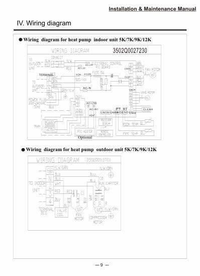
IV. Wiring diagram
Installation & Maintenance Manual
Wiring diagram for heat pump outdoor unit 5K/7K/9K/12K
Optional
AC-L33
AC-L44
CNO7
Cn22
CNO4
CLEAR
CNI2CNO1CNO2
PT RTCNO8/CNO9
AC-N1
AC-L55
HEAT
TERMINAL 3/ON 4/COM
AC-N
3502Q0027230
Wiring diagram for heat pump indoor unit 5K/7K/9K/12K
10
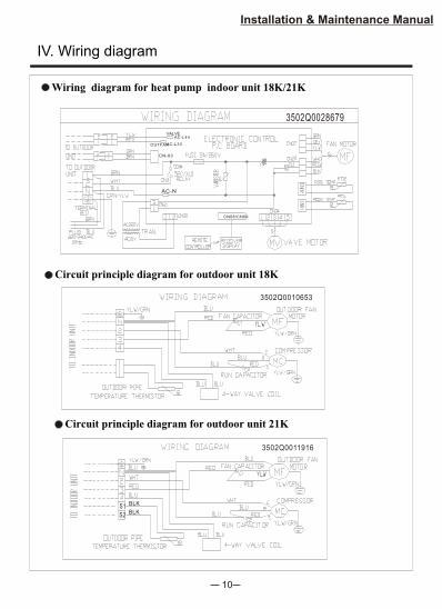
Installation & Maintenance Manual
Wiring diagram for heat pump indoor unit 18K/21K
Circuit principle diagram for outdoor unit 18K
AC-L44
AC-L33
CN-03
AC-N
CN08/CN09
3502Q0028679
VALVE
OUTFAN
3502Q0010653
Circuit principle diagram for outdoor unit 21K
3502Q0011916
S1
S2
BLK
BLK
IV. Wiring diagram
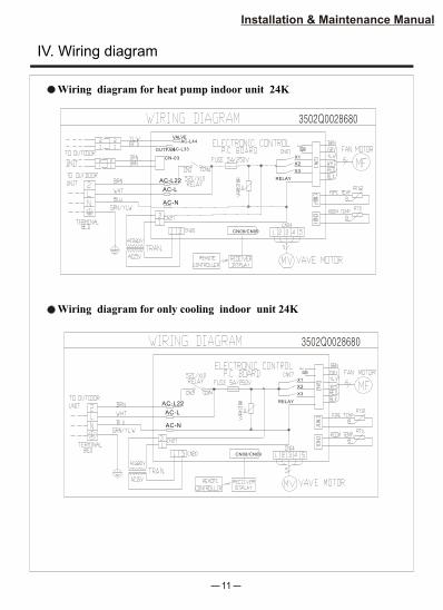
11
Installation & Maintenance Manual
Wiring diagram for heat pump indoor unit 24K
Wiring diagram for only cooling indoor unit 24K
AC-L44
AC-L33
CN-03
AC-N
CN08/CN09
3502Q0028680
VALVE
OUTFAN
X1
X2
X3
RELAY
AC-L
AC-L22
IV. Wiring diagram
AC-N
CN08/CN09
3502Q0028680
X1
X2
X3
RELAY
AC-L
AC-L22
12
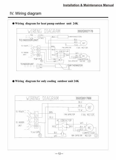
Installation & Maintenance Manual
Wiring diagram for heat pump outdoor unit 24K
Wiring diagram for only cooling outdoor unit 24K
IV. Wiring diagram
3502Q0017666
3502Q0027178
TO INDOOR UNITTEMP. THERMISTOR
TO INDOOR UNIT
4-WAY VAVLE COIL
13
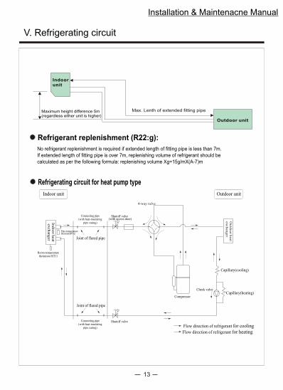
V. Refrigerating circuit
Installation & Maintenacne Manual
No refrigerant replenishment is required if extended length of fitting pipe is less than 7m.
If extended length of fitting pipe is over 7m, replenishing volume of refrigerant should be
calculated as per the following formula: replenishing volume Xg=15g/mX(A-7)m
Outdoor unit
Indoorunit
Maximum height difference 5m(regardless either unit is higher)
Max. Lenth of extended fitting pipe
Refrigerant replenishment (R22:g):
Refrigerating circuit for heat pump type
Capillary(heating)
Room-temperaturethermistor RT11
Pipe-temperaturethermisto
Indoor unit Outdoor unit
Indoor
heat
exchanger
Ou
tdo
or
heat
ex
ch
an
ger
Flow direction of refrigerant for cooling
Flow direction of refrigerant for heating
Joint of flared pipe
Connecting pipe(with heat-insulating
pipe casing)
Joint of flared pipe
Connecting pipe(with heat-insulating
pipe casing)
Shutoff valve (with access door)
Shutoff valve
4-way valve
Compressor
Check valve
Capillary(cooling)
14
Installation & Maintenance Manual
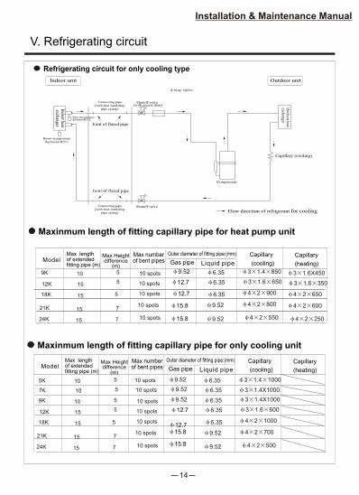
Maxinmum length of fitting capillary pipe for only cooling unit
Capillary
(cooling)
9K 10
15
9.52
12.7
6.35
6.3515
Model Gas pipe
Max lengthof extendedfitting pipe (m)
Outer diameter of fitting pipe:(mm)
Liquid pipe
12K
18K
15
15.8 9.52
21K
6.3512.7
5
5
5
Max Heightdifference
(m)
7
Max numberof bent pipes
10 spots
10 spots
10 spots
10 spots15
15.8 9.52
24K 7
10 spots
10 5
9.52 6.35
10 spots
9.52 6.3510 5 10 spots
7K
5K
Refrigerating circuit for only cooling type
Capillary (cooling)
Room-temperaturethermistor RT11
Pipe-temperaturethermisto
Indoor unit Outdoor unit
Indoorheat
exchanger
Outdoor
heatexchanger
Flow direction of refrigerant for cooling
Joint of flared pipe
Connecting pipe(with heat-insulating
pipe casing)
Joint of flared pipe
Connecting pipe(with heat-insulating
pipe casing)
Shutoff valve (with access door)
Shutoff valve
4-way valve
Compressor
Capillary
(heating)
4 2 500
4 2 1000
3 1.6 600
3 1.4X1000
4 2 700
3 1.4X1000
3 1.4 1000
Maxinmum length of fitting capillary pipe for heat pump unit
Capillary
(cooling)
9K 10
15
12.7 6.3515
Model Gas pipe
Max lengthof extendedfitting pipe (m)
Outer diameter of fitting pipe:(mm)
Liquid pipe
12K
18K
15
15.8 9.52
21K
6.3512.7
5
5
5
Max Heightdifference
(m)
7
Max numberof bent pipes
10 spots
10 spots
10 spots
10 spots 4 2 250
4 2 650
3 1.6 350
3 1.6X450
15
15.8 9.52
24K 7
10 spots
4 2 600
9.52 6.35
Capillary
(heating)
4 2 550
4 2 900
3 1.6 650
3 1.4 850
4 2 800
V. Refrigerating circuit
15
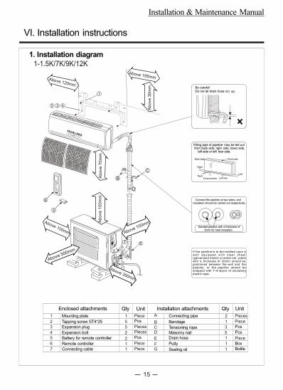
1-1.5K/7K/9K/12K
Above 100mmAb
ove
10
0m
mA
bo
ve
70
mm
Above 100mm
Above 350mm
Above 195mmAbove 120mm
Ab
ove
30
mm
7
A
C
D
B
E
6
5
Above 500mm
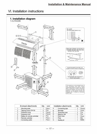
VI. Installation instructions
Installation & Maintenance Manual
Be careful! Do not let drain hose run up.
Connect the pipeline at two sides, andinsulation should be carried out respectively.
Fitting pipe of pipeline may be led out from back side, right side, lower side, left side or left rear side.
Left rear
Left
Right
Back side
RearDownwards
Front side
Aerated plastics with a thickness of 8mm for heat insulation
If the pipeline is to be installed upon awa l l equ ipped w i th s tee l shee t (galvanized sheet) or metal net, plankwith a thickness of 20mm should be positioned between the wall and thepipeline, or the pipeline should bewrapped with 7~8 layers of insulatingplastic tape.
Enclosed attachments Installation attachmentsQty
1
2
3
4
5
6
7
Mounting plate
Tapping screw ST4*25
Expansion plug
Expansion bolt
Battery for remote controller
Remote controller
Connecting cable
1
5
2
2
1
A
B
C
D
E
FG
Connecting pipe
Bandage
Tensioning rope
Masonry nail
Drain hose
Putty
Sealing oil
5
1
Unit
2
1
5
1
3
1
1
Pcs
Pcs
Qty Unit
Pcs
Box
Bottle
Piece
Pieces
Pieces
Piece
Piece
Pieces
Piece
Pcs
Piece
1. Installation diagram
HUALING
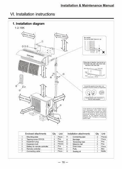
16
Installation & Maintenance Manual
Above 100mmAb
ove
10
0m
mA
bo
ve
70
mm
Above 100mm
Above 500mm
Above 350mm
Above 155mm
Above 105mm
Ab
ove
24
mm1
2 3 4
7
A
C
D
B
E
6
5
Be careful! Do not let drain hose run up.
Connect the pipeline at two sides, andinsulation should be carried out respectively.
Fitting pipe of pipeline may be led out from back side, right side, lower side, left side or left rear side.
Left rear
Left
Right
Back side
RearDownwards
Front side
Aerated plastics with a thickness of 8mm for heat insulation
If the pipeline is to be installed upon awa l l equ ipped w i th s tee l shee t (galvanized sheet) or metal net, plankwith a thickness of 20mm should be positioned between the wall and thepipeline, or the pipeline should bewrapped with 7~8 layers of insulatingplastic tape.
1. Installation diagram
1-2.18K
Enclosed attachments Installation attachmentsQty
1
2
3
4
5
6
7
Mounting plate
Tapping screw ST4*25
Expansion plug
Expansion bolt
Battery for remote controller
Remote controller
Connecting cable
1
5
2
2
1
A
B
C
D
E
FG
Connecting pipe
Bandage
Tensioning rope
Masonry nail
Drain hose
Putty
Sealing oil
5
1
Unit
2
1
5
1
3
1
1
Pcs
Pcs
Qty Unit
Pcs
Box
Bottle
Piece
Pieces
Pieces
Piece
Piece
Pieces
Piece
Pcs
Piece
HUALING
VI. Installation instructions
17
Installation & Maintenance Manual
1-3.21K/24K
Above 100mmAb
ove
10
0m
mA
bo
ve
70
mm
Above 100mm
Above 500mm
Above 350mm
Above 242mm
Above 175mm
Ab
ove
60
mm
1
2 3 4
7
A
C
D
B
E
6
5
Be careful! Do not let drain hose run up.
Connect the pipeline at two sides, andinsulation should be carried out respectively.
Fitting pipe of pipeline may be led out from back side, right side, lower side, left side or left rear side.
Left rear
Left
Right
Back side
RearDownwards
Front side
Aerated plastics with a thickness of 8mm for heat insulation
If the pipeline is to be installed upon awa l l equ ipped w i th s tee l shee t (galvanized sheet) or metal net, plankwith a thickness of 20mm should be positioned between the wall and thepipeline, or the pipeline should bewrapped with 7~8 layers of insulatingplastic tape.
1. Installation diagram
Enclosed attachments Installation attachmentsQty
1
2
3
4
5
6
7
Mounting plate
Tapping screw ST4*25
Expansion plug
Expansion bolt
Battery for remote controller
Remote controller
Connecting cable
1
5
2
2
1
A
B
C
D
E
FG
Connecting pipe
Bandage
Tensioning rope
Masonry nail
Drain hose
Putty
Sealing oil
5
1
Unit
2
1
5
1
3
1
1
Pcs
Pcs
Qty Unit
Pcs
Box
Bottle
Piece
Pieces
Pieces
Piece
Piece
Pieces
Piece
Pcs
Piece
HUALING
HUALING
VI. Installation instructions
18
Installation & Maintenance Manual
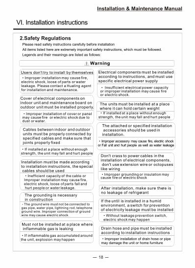
Warning
Users don't try to install by themselves
Improper installation may cause fire, electric shock, loose of parts or waterleakage. Please contact a Hualing agentfor installation and maintenance.
The units must be installed at a placewhere it can hold certain weight
Electrical components must be installed according to instructions, and must usespecific electrical power supply
Insufficient electrical power capacityor improper installation may cause fireor electric shock.
Cover of electrical components on indoor unit and maintenance board onoutdoor unit must be installed properly.
2.Safety RegulationsPlease read safety instructions carefully before installation
All items listed here are extremely important safety instructions, which must be followed.
Legends and their meanings are listed as follows:
Improper installation of cover or panelmay cause fire or electric shock due todust or water.
If installed at a place without enough strength, the unit may fall and hurt people
Cables between indoor and outdoor units must be properly connected byspecified cables and make sure thatjoints properly fixed
The attached or specified installation accessories should be used in installation
Improper accessory may cause fire, electric shock or Fall unit and hurt people as well as water leakage
If installed at a place without enough strength, the unit may fall and hurt people
Installation must be made according to installation instructions, the special cables should be used
After installation, make sure there is no leakage of refrigerant
Don't crass to power cables in the installation of electrical components, don't use extension wire or octopuseslike wiring
The grounding is necessaryin construction If the until is installed in a humid
environment, a switch for prevention of electricity leakage must be installed
Must not be installed at a place where inflammable gas is leaking Drain hose and pipe must be installed
according to installation instructions
Inefficient capacity of the cable orImproper installation may cause fire, electric shock, loose of parts fall and hurt people or water leakage.
Improper grounding or insulation may cause fire or electric shock
The ground wire must not be connected togas pipe, water pipe, lightning rod, telephone ground wire. Improper connection of groundwire may cause electric shock Without leakage prevention switch,
electric shock may happen
If inflammable gas accumulated around the unit, explosion may happen Improper installation of drain hose or pipe
may damage the unit or home furniture
VI. Installation instructions
19
Installation & Maintenance Manual
Above 175mm
Above 242mm
Above 60mm
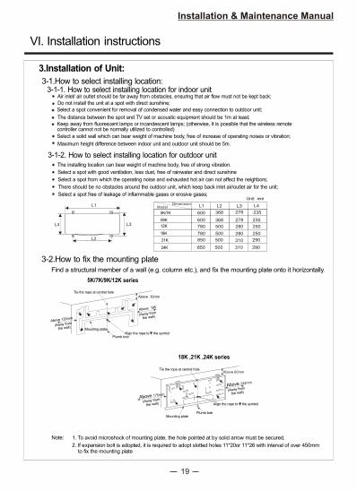
3-1.How to select installing location:3-1-1. How to select installing location for indoor unit
Air inlet/ air outlet should be far away from obstacles, ensuring that air flow must not be kept back;
Do not install the unit at a spot with direct sunshine;
Select a spot convenient for removal of condensed water and easy connection to outdoor unit;
The distance between the spot and TV set or acoustic equipment should be 1m at least;
Keep away from fluorescent lamps or incandescent lamps; (otherwise, it is possible that the wireless remotecontroller cannot not be normally utilized to controlled)
Select a solid wall which can bear weight of machine body, free of increase of operating noises or vibration;
Maximum height difference between indoor unit and outdoor unit should be 5m.
3-1-2. How to select installing location for outdoor unitThe installing location can bear weight of machine body, free of strong vibration.
Select a spot with good ventilation, less dust, free of rainwater and direct sunshine
Select a spot from which the operating noise and exhausted hot air can not affect the neighbors;
There should be no obstacles around the outdoor unit, which keep back inlet air/outlet air for the unit;
Select a spot free of leakage of inflammable gases or erosive gases;
3-2.How to fix the mounting plate
Find a structural member of a wall (e.g. column etc.), and fix the mounting plate onto it horizontally.
Tie the rope at central hole
Mounting plate Plumb bob
Align the rope to the symbol
(Away from
the wall)
(Away from
the wall)
1. To avoid microshock of mounting plate, the hole pointed at by solid arrow must be secured.
2. If expansion bolt is adopted, it is required to adopt slotted holes 11*20or 11*26 with interval of over 450mm to fix the mounting plate
Note:
18K ,21K ,24K series
L2 L3 L4L1
600 368 278 235 09K
780 500 280 250
Unit: mm
L1
L3L4
L2
12K
ModelDimension
850 500 310 290
Above 30mm
Plumb bob
Tie the rope at central hole
Mounting plate (Away from
the wall)
Above 195
Above 120mm(Away from
the wall)
Align the rope to the symbol
5K/7K/9K/12K series
3.Installation of Unit:
VI. Installation instructions
21K
18K
24K 850 500 310 290
780 500 280 250
5K/7K 600 368 278 235
20
Installation & Maintenance Manual
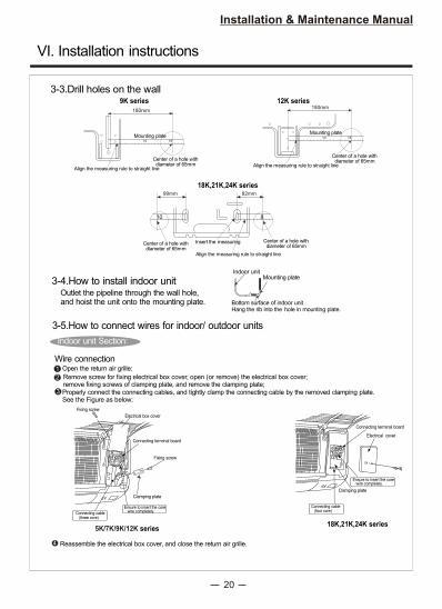
3-4.How to install indoor unitOutlet the pipeline through the wall hole,and hoist the unit onto the mounting plate.
3-3.Drill holes on the wall
10 18
180mm
Mounting plate
Align the measuring rule to straight line
Center of a hole with diameter of 65mm
10 18
180mm
Mounting plate
Align the measuring rule to straight line
Center of a hole with diameter of 65mm
810
82mm99mm
Center of a hole with diameter of 65mm
Center of a hole with diameter of 65mm
Align the measuring rule to straight line
Insert the measuring
18K,21K,24K series
9K series 12K series
Bottom surface of indoor unitHang the rib into the hole in mounting plate.
Indoor unitMounting plate
3-5.How to connect wires for indoor/ outdoor units
Indoor unit Section:
Wire connection
5K/7K/9K/12K series18K,21K,24K series
1 Open the return air grille;
2 Remove screw for fixing electrical box cover, open (or remove) the electrical box cover;remove fixing screws of clamping plate, and remove the clamping plate;
3 Properly connect the connecting cables, and tightly clamp the connecting cable by the removed clamping plate.See the Figure as below:
Electrical box cover
Ensure to insert the core wire completely.Connecting cable
(three core)
Clamping plate
Fixing screw
Fixing screw
Connecting terminal board
Connecting cable (four core)
Clamping plate
Ensure to insert the core wire completely.
Connecting terminal board
Electrical cover
Reassemble the electrical box cover, and close the return air grille.
VI. Installation instructions
21
Installation & Maintenance Manual
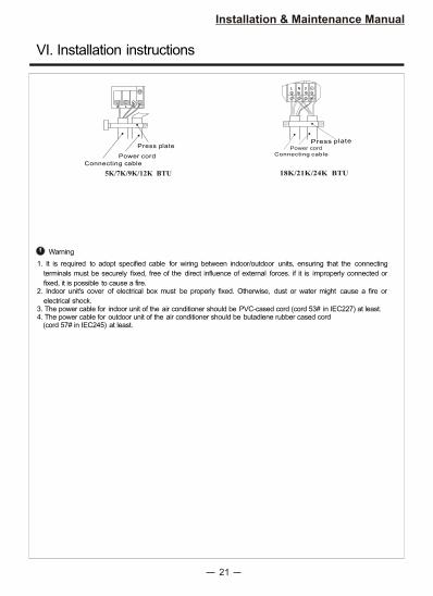
Warning
1. It is required to adopt specified cable for wiring between indoor/outdoor units, ensuring that the connecting
terminals must be securely fixed, free of the direct influence of external forces. if it is improperly connected or
fixed, it is possible to cause a fire.2. Indoor unit's cover of electrical box must be properly fixed. Otherwise, dust or water might cause a fire or
electrical shock.3. The power cable for indoor unit of the air conditioner should be PVC-cased cord (cord 53# in IEC227) at least.4. The power cable for outdoor unit of the air conditioner should be butadiene rubber cased cord (cord 57# in IEC245) at least.
Press plate
Connecting cable
Power cord
5K/7K/9K/12K BTU
Power cord
Connecting cable
18K/21K/24K BTU
Press plate
VI. Installation instructions
22
Installation & Maintenance Manual
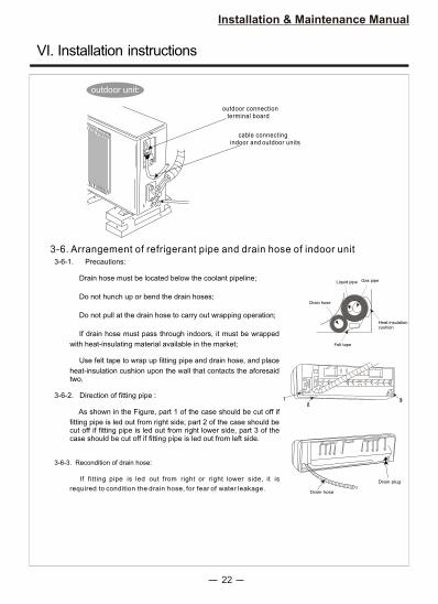
outdoor connection terminal board
cable connectingindoor and outdoor units
outdoor unit:
Drain hose
Drain plug
Heat-insulationcushion
Felt tape
Gas pipeLiquid pipe
Drain hose
3-6-1. Precautions:
Drain hose must be located below the coolant pipeline;
Do not hunch up or bend the drain hoses;
Do not pull at the drain hose to carry out wrapping operation;
If drain hose must pass through indoors, it must be wrapped
with heat-insulating material available in the market;
Use felt tape to wrap up fitting pipe and drain hose, and place
heat-insulation cushion upon the wall that contacts the aforesaid two.
3-6-2. Direction of fitting pipe :
As shown in the Figure, part 1 of the case should be cut off if
fitting pipe is led out from right side; part 2 of the case should be cut off if fitting pipe is led out from right lower side, part 3 of the case should be cut off if fitting pipe is led out from left side.
3-6-3. Recondition of drain hose:
If fitting pipe is led out from right or right lower side, it is
required to condition the drain hose, for fear of water leakage.
3-6. Arrangement of refrigerant pipe and drain hose of indoor unit
VI. Installation instructions
23
Installation & Maintenance Manual
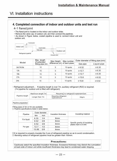
4. Completed connection of indoor and outdoor units and test run
4-1 flared jointThe flared joint is located on the indoor and outdoor sides. Remove the valve cap of outdoor unit, and then connect the pipelines.As shown in Figure below, coolant pipeline is used to connect indoor unit and
outdoor unit.
Connector
Refrigerant pipeline
Access door
Indoor unit
Outdoor unit
Liquid pipe
Refrigerant adjustment... If pipeline length is over 7m, auxiliary refrigerant (R22) is required. (7m pipeline for outdoor unit is filled with refrigerant)
Pipeline length
Maximum length 7m
Longer than 7m
Requiring no refrigerant replenishment
Requiring refrigerantreplenishment 50g/m
Pipeline preparation
Fitting pipes of 3m or 4m are available. Pipeline specifications listed in table below:
It is required to properly insulate the 2 pcs of refrigerant pipeline so as to avoid condensation. Bending radius of refrigerant pipeline must be greater than 100mm.
Pipeline
For liquid
For gas
Outer diameter
Mm Inch
6.35 1/4
Insulation thickness
6mm
Specific gravity of insulatingplastic foam is 0.0459.52 3/8
12.7 1/2
6mm
6mm
Insulating material
Precautions:
Cautiously select the specified insulation thickness. Excessive thickness may disturb the cumulation at back side of indoor unit while insufficient thickness may lead to condensed water dripping.
Gas pipe
5K/7K/9k 10
15
9.52
12.7
6.35
6.3515
ModelGas pipe
Max length of extended fitting pipe (m)
Outer diameter of fitting pipe:(mm)
Liquid pipe
12k
18k
15 15.8 9.5221k
6.3512.7
5
5
5
Max Heightdifference (m)
5
Max number of bent pipes
10 spots
10 spots
10 spots
10 spots
9.52 3/8 6mm
15.88 5/8 6mm
VI. Installation instructions
15 15.8 9.5224k 5 10 spots
24
Installation & Maintenance Manual
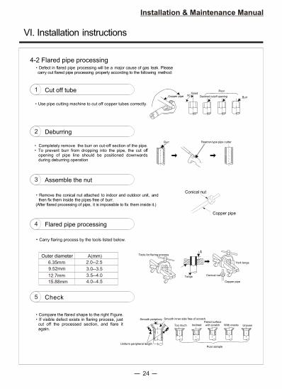
4-2 Flared pipe processingDefect in flared pipe processing will be a major cause of gas leak. Please
carry out flared pipe processing properly according to the following method:
Burr Reamer-type pipe cutter
Copper pipe 90 Declined cutoff opening
Poor
Burr
Good1 Cut off tube
Use pipe cutting machine to cut off copper tubes correctly.
2 Deburring
3 Assemble the nut
Remove the conical nut attached to indoor and outdoor unit, and then fix them inside the pipes free of burr.
(After flared processing of pipe, it is impossible to fix them inside it.)
4 Flared pipe processing
Carry flaring process by the tools listed below.
Outer diameter
6.35mm
9.52mm
12.7mm
A( )mm
2.0--2.5
3.0--3.5
3.5--4.0 TongsConical nut
Copper pipe
York tongs
Tools for flaring process
5 Check
Smooth inner side free of scratch
Too much InclinedFlared surface
with scratch With cracks Uneven
Poor sample
Smooth periphery
Uniform peripheral length
Compare the flared shape to the right Figure. If visible defect exists in flaring process, just cut off the processed section, and flare it again.
Conical nut
Copper pipe
Completely remove the burr on cut-off section of the pipe.To prevent burr from dropping into the pipe, the cut offopening of pipe line should be positioned downwards during deburring operation
15.88mm 4.0--4.5
VI. Installation instructions
25
Installation & Maintenance Manual
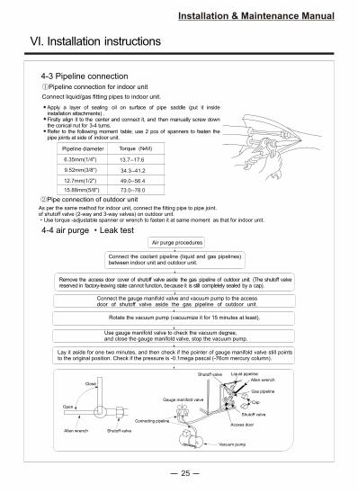
4-3 Pipeline connection
4-4 air purge Leak test
Connect liquid/gas fitting pipes to indoor unit.
Pipeline diameter
6.35mm(1/4")
9.52mm(3/8")
Torque (N M)
12.7mm(1/2")
13.7--17.6
34.3--41.2
49.0--56.4
Pipeline connection for indoor unit
As per the same method for indoor unit, connect the fitting pipe to pipe joint.of shutoff valve (2-way and 3-way valves) on outdoor unit.
Use torque -adjustable spanner or wrench to fasten it at same moment as that for indoor unit.
Pipe connection of outdoor unit
Air purge procedures
Connect the coolant pipeline (liquid and gas pipelines) between indoor unit and outdoor unit.
Remove the access door cover of shutoff valve aside the gas pipeline of outdoor unit. (The shutoff valvereserved in factory-leaving state cannot function, because it is still completely sealed by a cap).
Connect the gauge manifold valve and vacuum pump to the accessdoor of shutoff valve aside the gas pipeline of outdoor unit.
Rotate the vacuum pump (vacuumize it for 15 minutes at least).
Use gauge manifold valve to check the vacuum degree,and close the gauge manifold valve, stop the vacuum pump.
Lay it aside for one two minutes, and then check if the pointer of gauge manifold valve still points to the original position. Check if the pressure is -0.1mega pascal (-76cm mercury column).
Close
Open
Allen wrench Shutoff valve
Shutoff valve Liquid pipeline
Allen wrench
Gas pipeline
Cap
Shutoff valve
Access door
Vacuum pump
Connecting pipeline
Gauge manifold valve
Apply a layer of sealing oil on surface of pipe saddle (put it inside installation attachments) . Firstly align it to the center and connect it, and then manually screw down the conical nut for 3-4 turns. Refer to the following moment table; use 2 pcs of spanners to fasten the pipe joints at side of indoor unit.
15.88mm(5/8") 73.0--78.0
VI. Installation instructions

26
Installation & Maintenance Manual
4-5 Insulation and bandage wrapping
Cover the fitting pipe sleeve by pipe cap; All fitting pipes and valves of outdoor unit should be heat-insulated; All fitting pipes from the fitting pipe entry of outdoor unit must be wrapped with pipeline bandage;
Fix the ends of pipeline bandage by tapes applied with adhesive; if fitting pipe passes ceiling board, lavatory or other place with high temperature and humidity, the thickness of heat-insulating material should be increased for fear of condensation.
Quickly remove gauge manifold valve from access door for shutoff valve.
Maximum pipelinelength of 7m,
requiring no aeration.
If pipeline length islonger than 7m,
aerate it with amount of gas.
Screw down the access door cover to get the initial state.
And then screw down the cap.
Leak test
Screwing-down torque
Access door cover
Valve rod cap ofshutoff valve
(N m) (Kgf cm)
13.7 17.7
19.6 29.4
140 180
200 300
4-6 Arrangement of drain pipeline
Declined Upwards
Water leak Water leak Air retentioninside pipeline Water leak
Drain retention
AirEnd of drain hosedipping into water
Less than 50mmabove the floor
(Figure 1) (Figure 2) (Figure 3) (Figure 4) (Figure 5)
Drain hose
Hose (inner diameterof 15cm) or hard PVC pipe
Properly connect and evacuate the refrigerant pipeline, and fully open all shutoff valves aside the gas and liquid pipeline. If it is not operated with fully opened shutoff valves, performance of the unit may be degraded, resulting in troubles.
For easier drainage through drain pipeline, ensure that the drain pipeline should be positioned in a declined mode (as shown in Figure 1).Do not connect the drain pipeline in the same way as shown in Figure 2 - Figure 5.
If the length of drain hose assembled on the indoor unit is too short for operation, just connect the drain hose in the attachment box to it for operation.
If the drain hose has to pass the indoor spaces, it must be wrapped with heat-insulating material available in the market.
VI. Installation instructions
27
Installation & Maintenance Manual
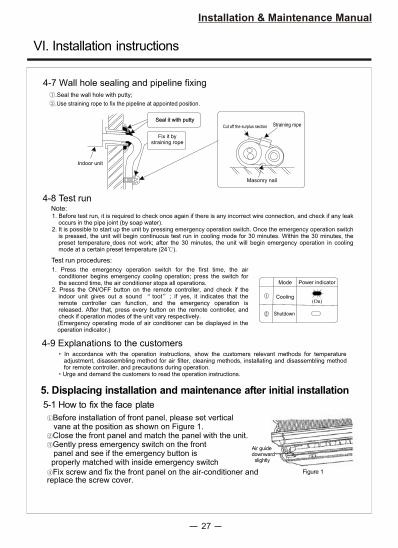
4-7 Wall hole sealing and pipeline fixing .Seal the wall hole with putty;
.Use straining rope to fix the pipeline at appointed position.
Straining rope Cut off the surplus section
Masonry nail
Indoor unit
Fix it bystraining rope
4-8 Test run
Test run procedures:
Note:
4-9 Explanations to the customers
Mode Power indicator
Cooling
Shutdown
(On)
Seal it with putty
1. Before test run, it is required to check once again if there is any incorrect wire connection, and check if any leakoccurs in the pipe joint (by soap water).
2. It is possible to start up the unit by pressing emergency operation switch. Once the emergency operation switch is pressed, the unit will begin continuous test run in cooling mode for 30 minutes. Within the 30 minutes, the preset temperature does not work; after the 30 minutes, the unit will begin emergency operation in cooling mode at a certain preset temperature (24 ).
1. Press the emergency operation switch for the first time, the air conditioner begins emergency cooling operation; press the switch for the second time, the air conditioner stops all operations.
2. Press the ON/OFF button on the remote controller, and check if the indoor unit gives out a sound toot ; if yes, it indicates that the remote controller can function, and the emergency operation is released. After that, press every button on the remote controller, and check if operation modes of the unit vary respectively.(Emergency operating mode of air conditioner can be displayed in the operation indicator.)
In accordance with the operation instructions, show the customers relevant methods for temperature adjustment, disassembling method for air filter, cleaning methods, installating and disassembling method for remote controller, and precautions during operation.Urge and demand the customers to read the operation instructions.
Air guide downward slightly
Figure 1
5. Displacing installation and maintenance after initial installation
5-1 How to fix the face plate
Fix screw and fix the front panel on the air-conditioner and replace the screw cover.
Before installation of front panel, please set vertical vane at the position as shown on Figure 1.
Close the front panel and match the panel with the unit.Gently press emergency switch on the front
panel and see if the emergency button is properly matched with inside emergency switch
VI. Installation instructions
28
Installation & Maintenance Manual
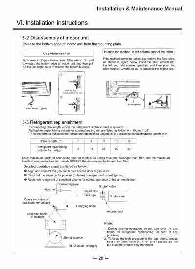
5-2 Disassembly of indoor unit
Release the bottom edge of indoor unit from the mounting plate.
Use Allen wrenchIn case the method in left column cannot be taken
As shown in Figure below, use Allen wrench to pull downward the bottom edge of indoor unit, and then pullout the unit slight so as to release the bottom buckles;.
If the method cannot be taken, just remove the face plate. As shown in Figure below, insert the allen wrench into the left and right square openings; and then push theallen wrench upward so as to descend the indoor unit,
Insert the Allen wrench, and hook the end.
Allen wrench (4cm)
Square openingPush Downward
5-3 Refrigerant replenishment
Detailed operation steps are listed as follow:
Align and connect the gas bomb onto access door of gas valve;
Carry out the air purge for pipeline (or hose) from gas bomb of refrigerant;
Replenish refrigerant of specified volume for normal operation of the air conditioner.
Connecting pipe
Indoor unitShutoff valve
Outdoor unit
Liquid pipe
Gas pipe
Charging hose
Access door
(R-22 liquid ) charging
Spring balance
Charging bottleof coolant
Operation valve ofgas bomb for coolant
Note:
Pipe length (m)
Refrigerant replenishing volume for unit(g)
If connecting pipe length is over 7m, refrigerant replenishment is required. Refrigerant replenishing volume for cooling/heating unit are listed as follow: A = 15g/m * (L-7) . (A in the formula indicates the refrigerant replenishing volume in g; L indicates connecting pipe length in m)
Note: maximum length of connecting pipe for models 25 Series must not be longer than 10m, and the maximum length of connecting pipe for models 35/50/70 Series must not be longer than 15m.
1. During charing operation, do not turn over the gas bomb for refrigerant replenishing for fear of any problem;
2. To keep the high pressure in the gas bomb, please heat it by warm water (40 ) in cold seasons. Do not put it on fire, or heat it by hot steam.
VI. Installation instructions
29
VII. Troubleshooting
installation & Maintenance Manual
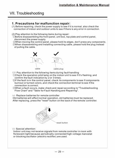
1. Precautions for malfunction repair:(1) Before repairing, check the power supply to see if it is normal, also check the
connection of indoor and outdoor units to see if there is any error in connection.
(2) Play attention to the following items during repair:Before disassembling the front panel, unit box, top plate and control panel,disconnect the power supply.When moving the control panel, please hold its edges, don't press any components.When disassembling and installing connecting cable, please hold the plug insteadof pulling the cable.
cable cable plug
Pay attention to the following items during fault handlingCheck the operation pilot lamp on the indoor unit to see if it's flashing, and
confirm the fault indication by 2 or 3 times.If the fault is in the control panel, check its components to see if components
burnout or turned colors, and check the connection terminal to see if the connection is correct.
When a fault occurs, make check and repair according to "Troubleshooting Flow Chart" and "Table for Fault Handling and Repairing".
Replace batteries for remote controller Old batteries will affect normal operation, old batteries must be replaced. After replacing, press the "reset" button on the back of the remote controller.
reset button
Special attention: Indoor unit may not receive signals from remote controller in room with florescent light because periodically-connected high-voltage manostat or blocking oscillator (electric rectifier) are used.
30
VII. Troubleshooting
installation & Maintenance Manual
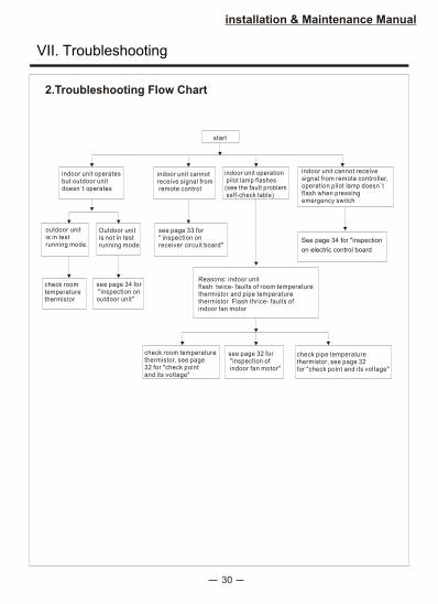
2.Troubleshooting Flow Chart
start
indoor unit operatesbut outdoor unitdoesn`t operates
indoor unit cannotreceive signal from remote control
indoor unit operation pilot lamp flashes(see the fault problem self-check table)
indoor unit cannot receivesignal from remote controller,operation pilot lamp doesn`tflash when pressingemergency switch
outdoor unitis in testrunning mode.
Outdoor unitis not in testrunning mode
see page 33 for" inspection onreceiver circuit board"
check roomtemperaturethermistor
see page 34 for "inspection onoutdoor unit"
Reasons: indoor unitflash twice- faults of room temperaturethermistor and pipe temperaturethermistor Flash thrice- faults ofindoor fan motor
see page 32 for "inspection of indoor fan motor"
check pipe temperaturethermistor, see page 32for "check point and its voltage"
check room temperaturethermistor, see page32 for "check pointand its voltage"
See page 34 for "inspection
on electric control board

Inst
alla
tion &
Mai
nte
nac
ne M
anual
NO
,T
roub
le d
ispl
ayS
ympt
omV
erif
ying
met
hod
Mai
nten
ance
Du
rin
g o
pera
tio
n,
sho
rtcir
cu
it a
nd o
pen
cir
cu
it t
he
ind
oo
rro
om
tem
pera
ture
therm
isto
rfo
r 2
seco
nd
s re
specti
vely
.
Out
door
un
itfa
ils
to r
un
Che
ck i
f th
erm
isto
r is
ou
t of
wor
k
Rec
onne
ctth
e pl
ug
Che
ck t
he i
ndo
orci
rcui
t bo
ard
Fli
cker
s tw
ice
and
ON
for
5 s
econ
ds r
epea
tedl
y
Roo
mte
mpe
ratu
re t
herm
isto
r
Fli
cker
s th
rice
an
d O
N f
or5
seco
nds
repe
ated
ly.
Indo
or f
an m
otor
runs
fo
r 12
se
cond
s an
d st
ops
for
3 m
inut
es. M
otor
is d
amag
ed,a
ndfa
n fa
ils
to r
un.
Che
ckth
e in
door
ele
ctri
cal
cont
rol
boar
d
Che
ck t
he ind
oor
fan
mot
or
Rep
lug
the
plug
Indo
or f
an
mot
or
Pip
e-te
mpe
ratu
reth
erm
isto
r
Che
ck i
f th
e th
erm
isto
r is
ou
t of
wor
k
Rec
onne
ct t
he
plug
Che
ck t
he i
ndoo
r ci
rcui
tbo
ard
Out
door
un
itfa
ils
to r
un
Fli
cker
s fo
r fo
ur t
imes
and
ON
for
5 se
cond
s re
peat
edly
.
When
the
indoor
fan m
oto
rru
ns
for
the
12 s
econds,
it
is
imposs
ible
to e
mit
fee
dbac
k
signal
of
rota
tion s
pee
d.
unplu
g the
plu
g C
N211,
mea
sure
the
sect
ion
bet
wee
n C
n121
, a
nd
ver
ify if
signal
is
over
1.5
V--
Duri
ng o
per
atio
n,
short
circ
uit
and o
pen
cir
cuit
th
e in
door
pip
e-te
mper
ature
th
erm
isto
r fo
r 2 s
econds
3.T
roub
le s
elfc
heck
ing
tabl
eBe
fore t
rouble
shooti
ng, e
nsure
that th
e sym
ptom
reoccu
rsfor
precis
e jud
geme
nt.
9K/1
2K/1
8K
Dou
ble
8 of
LE
D d
ispl
ay
E2
E6
E1
Ou
tdo
or
de
fro
sti
ng
th
erm
isto
rE
5O
utd
oo
r u
nit
do
esn
'to
pe
rate
Ch
eck t
o s
ee w
he
the
rth
erm
isto
r is
in
eff
ecti
ve
.R
eco
nn
ect
socke
t.C
he
ck ind
oo
r cir
cu
itb
oa
rd.
Aft
er
co
mp
resso
ris
sta
rte
d,d
efr
ost
the
rmis
tor
is c
on
ne
cte
do
rd
isco
nn
ecte
d.
Tro
uble
so
urce
1 2 43VII
.Tro
uble
shooti
ng
32
3.528
2.510
2.0
4.61
1.04
2.860
0.885
1.773
315 ~385
~308
~
~
76 ~93
81 ~
33 ~40
58 ~70
CSU-09HHAA CSU-12HHAA CSU-21HHAA CSU-24HHAB
267 ~
295 ~
218 ~
~
~138
87 ~107
installation & Maintenance Manual
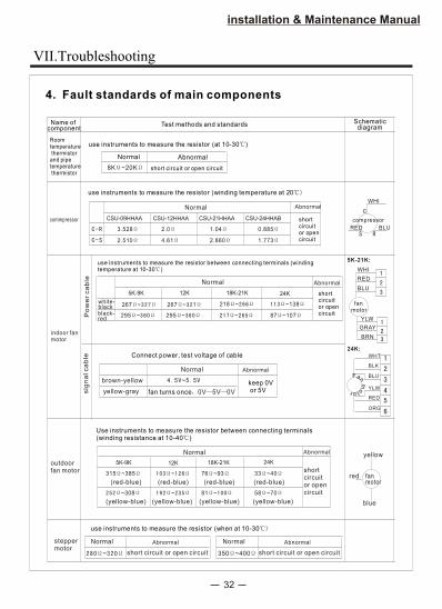
4. Fault standards of main components
Name ofcomponent
Test methods and standards Schematic diagram
Roomtemperature thermistorand pipetemperature thermistor
use instruments to measure the resistor (at 10-30 )
Normal Abnormal
short circuit or open circuit8K ~20K
commpressor
use instruments to measure the resistor (winding temperature at 20
WHI
BLURED
compressor
Normal Abnormal
shortcircuitor opencircuit
use instruments to measure the resistor between connecting terminals (windingtemperature at 10-30 )
Po
we
rca
ble
white-blackblack-red
Normal Abnormal
shortcircuitor opencircuit
indoor fanmotor
sig
na
lca
ble Connect power, test voltage of cable
brown-yellow
yellow-gray
~
fan turns once 0V 5V 0V
keep 0V or 5V
Normal Abnormal
fanmotor
WHI
RED
BLU
YLW
GRAY
BRN
outdoorfan motor
Use instruments to measure the resistor between connecting terminals(winding resistance at 10-40 )
shortcircuitor opencircuit
Normal Abnormal
(red-blue)
(yellow- )blue
(red-blue) (red-blue) (red-blue)
(yellow- )blue (yellow- )blue (yellow- )blue
fanmotor
yellow
blue
red
steppermotor
use instruments to measure the resistor (when at 10-30
~
Normal Abnormal
short circuit or open circuit
5K-9K 12K 18K-21K 24K
5K-9K 12K 18K-21K 24K
350 ~400
Normal Abnormal
short circuit or open circuit
267 ~
295 ~
Fanm
otr o
WHT
BLU
BLK
ORG
RED
YLW
5K-21K:
24K:
VII.Troubleshooting
33
installation & Maintenance Manual
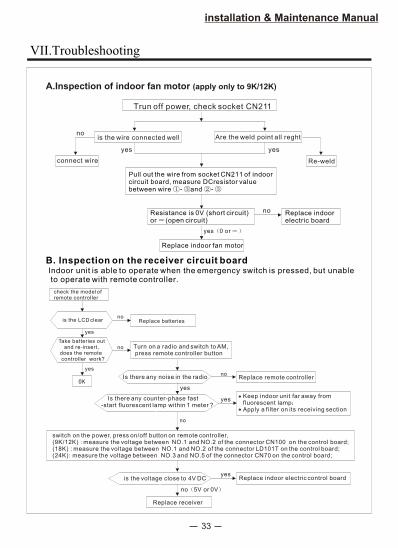
Indoor unit is able to operate when the emergency switch is pressed, but unable to operate with remote controller.
A.Inspection of indoor fan motor (apply only to 9K/12K)
B. Inspection on the receiver circuit board
Trun off power, check socket CN211
is the wire connected well
Pull out the wire from socket CN211 of indoorcircuit board, measure DCresistor value between wire - and -
Are the weld point all reght
connect wire
no
Re-weld
yes
Resistance is 0V (short circuit) or (open circuit)
Replace indoor fan motor
yes 0 or
Replace indoorelectric board
check the model of remote controller
is the LCD clear
Take batteries out and re-insert,
does the remote controller work?
Replace batteriesno
Turn on a radio and switch to AM, press remote controller button
Is there any noise in the radio
Is there any counter-phase fast-start fluorescent lamp within 1 meter ?
yes
Replace remote controller
Keep indoor unit far away fromfluorescent lampApply a filter on its receiving section
switch on the power, press on/off button on remote controller, measure the voltage between NO.1 and NO.2 of the connector CN100(9K/12K) : on the control board;
(18K) : measure the voltage between NO.1 and NO.2 of the connector LD101T on the control board;(24K): measure the voltage between NO.3 and NO.5 of the connector CN70 on the control board;
is the voltage close to 4V DC
no 5V or 0V
Replace receiver
Replace indoor electric control board
yes
no
yes
no
yesno
yes
no
yes
VII.Troubleshooting
34
installation & Maintenance Manual
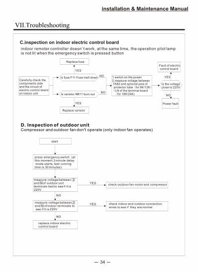
C.inspection on indoor electric control board
D. Inspection of outdoor unitCompressor and outdoor fan don't operate (only indoor fan operates)
indoor remoter controller doesn`t work, at the same time, the operation pilot lamp is not lit when the emergency switch is pressed button
Carefully check thecomponents sideand the circuit ofelectric control boardon indoor unit
Replace fuse
Is fuse F11 Fuse melt down
Is varistor NR11 burn out
Replace varistor
NO
YES
1.switch on the power2.measure voltage between TAB2 and optional pole of protector tube for 9K/12K / LN of the terminal board
for 18K/24K)
Fault of electric control board
Is the voltageclose to 220V
Power fault
start
check outdoor fan motor and compressorYES
press emergency switch: (atthis moment,3 minute delay mode starts, test runningtime is 30 minutes)
measure voltage between 2and N of outdoor unit terminals bed to see if it is220V
measure voltage between 2and N of indoor terminals to see if it is 220V
replace indoor electric control board
NO
check indoor and outdoor connection wires to see if they are normal
NO
YES
YES
NO
NO
YES
VII.Troubleshooting
35
installation & Maintenance Manual
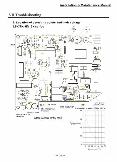
E. Location of detecting points and their voltage
1.5K/7K/9K/12K series
Indoor electrical control board
HL25GVX002AHL25GVX002A
BU
ZB
UZ
R21
RT1RT1
RT2RT2
R20
CN112(PT)R47
SW1
C33
C26C26
C27C27
J18
CN111(RT)
R31
R48
CN121
1 3
R23
IEC
12
7fu
se
T5
AL
25
0V
IEC
12
7fu
se
T5
AL
25
0V
UL
-fuse
5A
25
0V
CN1515 1
D6
C32A
C32A
J1
D7
D8
RB
3
RA
3R
A3
TR16
JP
HJP
H
J17J17
RU
3
RU
4R
U4
JP
MJP
M
1
R32
7C
N100
CN
100
R14
R12
R44
R11
IC6
J16
R53
TR13
RU
2R
U2
R54
R55
RU
1R
U1
R52
JF
1
JF
2JF
2
C25
C24
J2
CSTCST
IC2
C14
R49
D9
RB
1
CLK
C31
J14
J15
A/B
J13
R13RB2RB2RB4
R22
IC1
24
IC1
R51
R50J10
8
TR10
DATE:2003-10-16DATE:2003-10-16
9012
TR
15
TR14TR14+5V
J12
TR
17
TR
17
RA
2
RA
4
RA
1
IC3
IEC
12
7fu
se
T5
AL
25
0V
IEC
127fu
seT
5A
L250V
CAUTION: HIGH VOLTAGE !CAUTION: HIGH VOLTAGE !
X64
LD62(YLW)LD62(YLW)
X63
LD63(RED)LD63(RED)
X62
UL
-fuse
5A
25
0V
UL
-fuse
5A
25
0V
R62
C5
R63
C6 TAB2(BLU)TAB2(BLU)FU
SE
FU
SE
NR11NR11
CN
211
CN
211
LD65(BLU)LD65(BLU)
C7
R61
+R40
52C/X1052C/X10
TR11
J4
J3
R25
J6
J5
LD64(BRN)LD64(BRN)
TR12
R46
C32
R24J8
C13 C28
D1
C30
R43 D4
D3
D2
R30
J7
J7
R45
J9
C1
C1
L102
C4
J19
IC8
TRAN
D10
C22
J11
R42
C23
R41
GND
D5
C12
+
C21
IC5C11+
C10
C20
IC4
R60R60
IC7
C3
R145
Room temperature thermistor
Pipe-temperaturethermistor
Emergency switch
Characteristics of resistors RT11 and RT12
Resistance value K
Temperature
VII.Troubleshooting
36
installation & Maintenance Manual
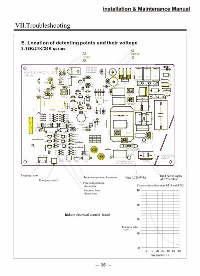
E. Location of detecting points and their voltage
3.18K/21K/24K series
Temperature
Resistance value
Indoor electrical control board
Characteristics of resistors RT11 and RT12
-
+
DC12VDC12VDC5V+
-
Input power supplyAC220V/240V
Fuse AC250V/5AEmergency switch
Stepping motor Room temperature thermistor
Pipe-temperature thermistor
Remove frost thermistor
VII.Troubleshooting
indoor unit
37
Installation & Maintenance Manual
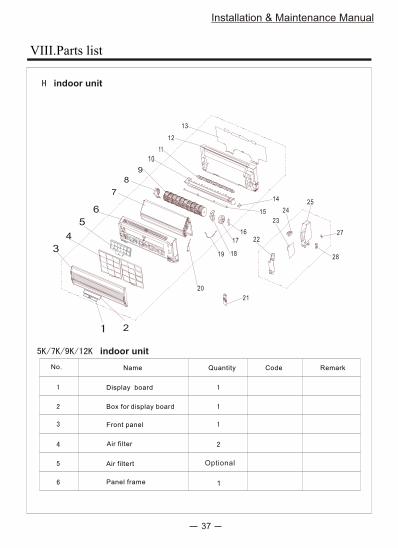
Optional
Air filter
Front panel
Panel frame
Box for display board
Display board
Air filtert
1
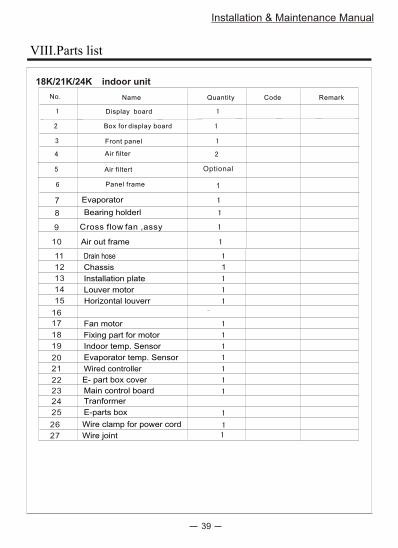
No. Name Quantity Code Remark
VIII.Parts list
6
5
4
3
2
12
11
10
9
8
7
22
23
24
25
19 18
17
16
15
14
13
21
20
28
27
indoor unit
38
Installation & Maintenance Manual
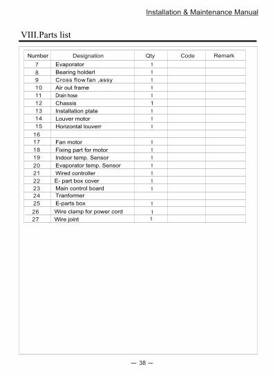
Number Designation Qty Code Remark
7
8
9
10
11
12
13
14
15
16
17
18
19
20
21
22
23
24
Evaporator
1
Bearing holderl
Cross flow fan ,assy
Air out frame
Drain hose
Chassis
Installation plate
Louver motor
Horizontal louverr
Fan motor
Fixing part for motor
Indoor temp. Sensor
Evaporator temp. Sensor
Wired controller
Main control board
25
Tranformer
E-parts box
VIII.Parts list
E- part box cover
26
27
Wire clamp for power cord
Wire joint
39
Installation & Maintenance Manual
VIII.Parts list
18K/21K/24K indoor unit
Optional
Air filter
Front panel
Panel frame
Box for display board
Display board
Air filtert
1
No. Name Quantity Code Remark
7
8
9
10
Evaporator
Bearing holderl
Cross flow fan ,assy
Air out frame
11
12
13
14
15
16
17
18
19
20
21
22
23
24
1
Drain hose
Chassis
Installation plate
Louver motor
Horizontal louverr
Fan motor
Fixing part for motor
Indoor temp. Sensor
Evaporator temp. Sensor
Wired controller
Main control board
25
Tranformer
E-parts box
E- part box cover
26
27
Wire clamp for power cord
Wire joint
5K,7K,9K, series outdoor unit
40
Installation & Maintenance Manual
2
3
4
5
6
7
8
9
19
VIII.Parts list

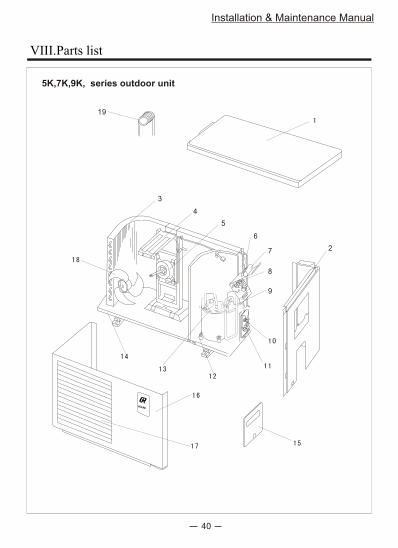
5K/7K/9K series outdoor unit
41
Installation & Maintenance Manual
1
2
3
4
5
6
7
8
9
10
11
12
13
14
15
16
17
18
19
1.5 F/450V
3
1/4F
3/8F
1
44R212AE-FJSMC
TB
C1
MF
30 F/450V
Number Designation Qty Code Note
Top plate
Right side plate
Heat exchanger
Motor mounting
Fan motor
Capacity of fan
Capacity of compressor
Terminal block
Return air pipe
Shutoff valve (liquid)
Shutoff valve (gas)
Compressor
Rubber shock absorberof compressor
Base
Maintenance panel
Foreplate
Outdoor grille
Axial flow fan
Capillary
YDK-20AF-6
VIII.Parts list
12K,18K series outdoor unit
42
3
4
5
6
7
8
17
18
13
14
15
16
19
20
1011 9
Installation & Maintenance Manual
VIII.Parts list
43
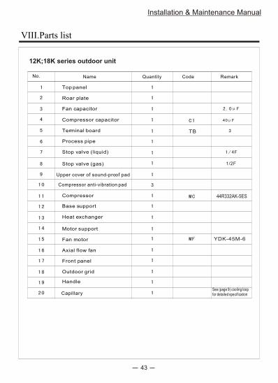
TB
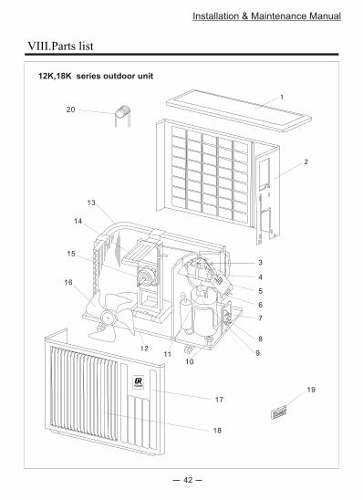
44R332AK-5ES
1/2F
12K;18K series outdoor unit
Installation & Maintenance Manual
Top panel
Roar plate
Fan capacitor
Compressor capacitor
Terminal board
Process pipe
Stop valve (liquid)
Stop valve (gas)
Base support
Heat exchanger
Motor support
Fan motor
Axial flow fan
Front panel
Outdoor grid
Handle
Compressor
Compressor anti-vibration pad
Upper cover of sound-proof pad
Capillary
No. Name Quantity Code Remark
See (page 9) cooling loopfor detailed specification
YDK-45M-6
VIII.Parts list
44
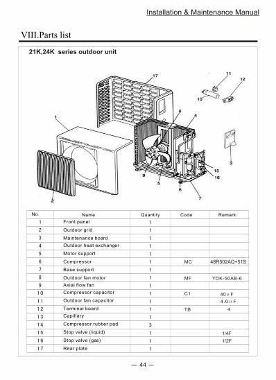
21K,24K series outdoor unit
Installation & Maintenance Manual
MF
MC 48R502AQ+51S
C1 40 F
4.0 F
TB 4
Maintenance board
Outdoor heat exchanger
Motor support
Compressor
Base support
Outdoor fan motor
Axial flow fan
Compressor capacitor
Outdoor fan capacitor
Stop valve (liquid)
Compressor rubber pad
Stop valve (gas)
Front panel
Outdoor grid
Terminal board
Capillary
Rear plate
No. Name Quantity Code Remark
1/2F
1/4F
YDK-50AB-6
VIII.Parts list
45
Installation & Maintenance Manual
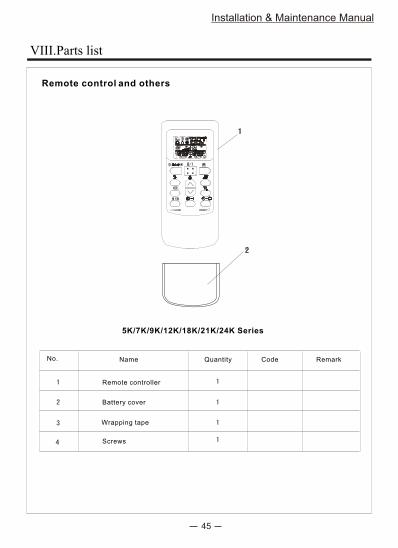
Remote control and others
Remote controller
Battery cover
Wrapping tape
Screws
No. Name Quantity Code Remark
5K/7K/9K/12K/18K/21K/24K Series
VIII.Parts list
2005.12.20

第 2 页 共 59 页
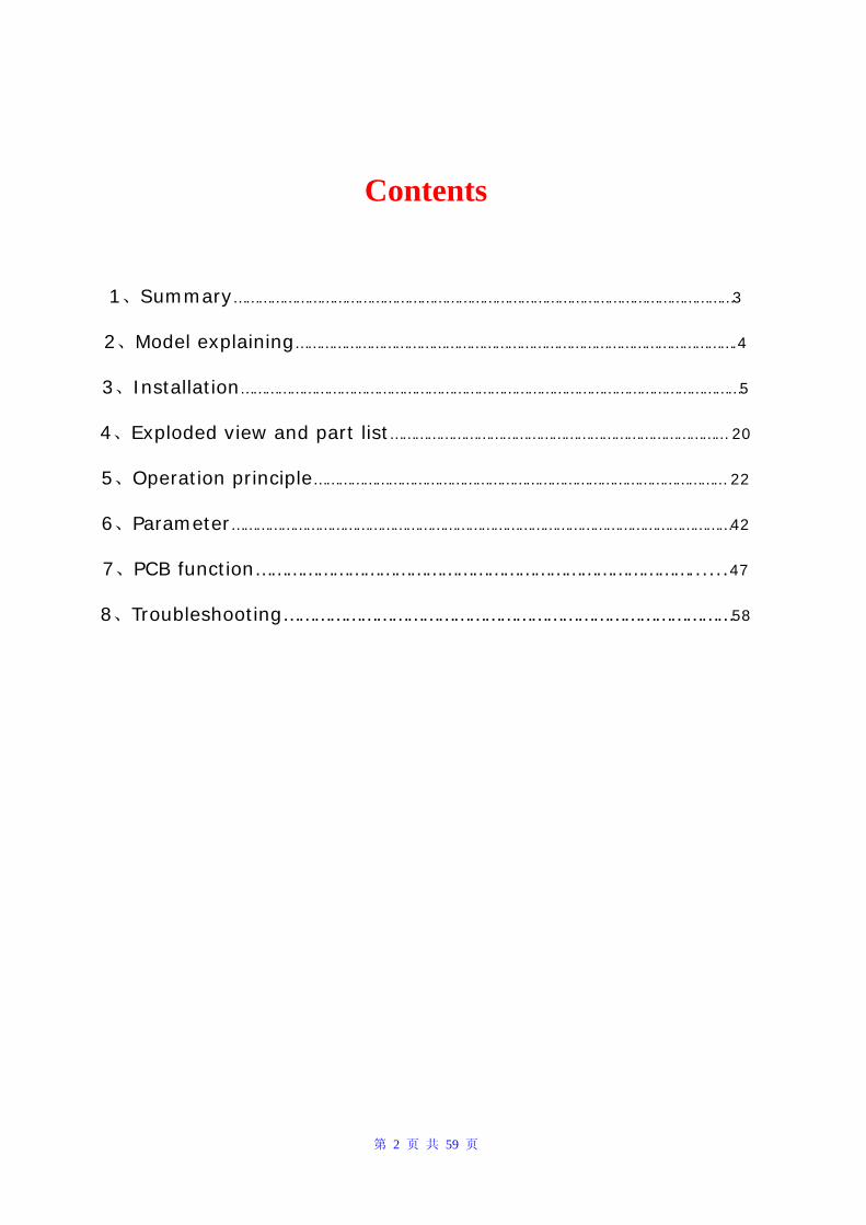
Contents
1、Summary…………………………………………………………………………………………………………3
2、Model explaining…………………………………………………………………………………………….4
3、Installation…………………………………………………………………………………………………………5
4、Exploded view and part list……………………………………………………………………… 20
5、Operation principle……………………………………………………………………………………… 22
6、Parameter…………………………………………………………………………………………………………42
7、PCB function…………………………………………………………………………......47
8、Troubleshooting……………………………………………………………………………58
第 3 页 共 59 页
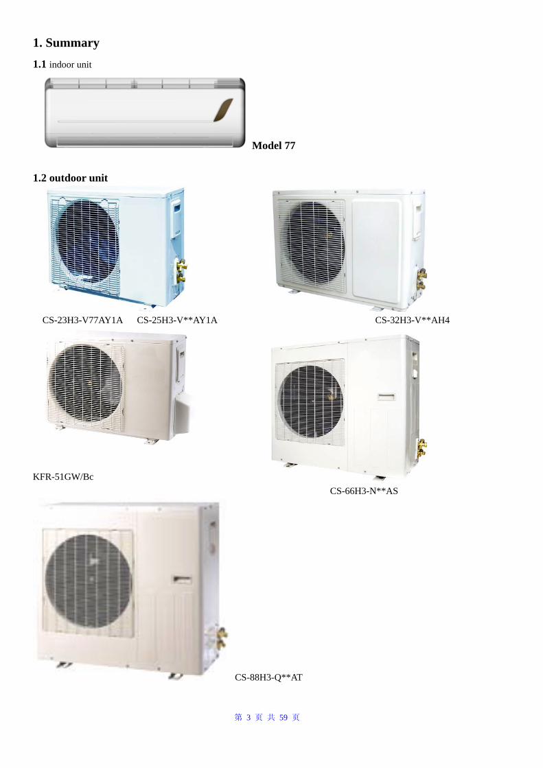
1. Summary 1.1 indoor unit
Model 77
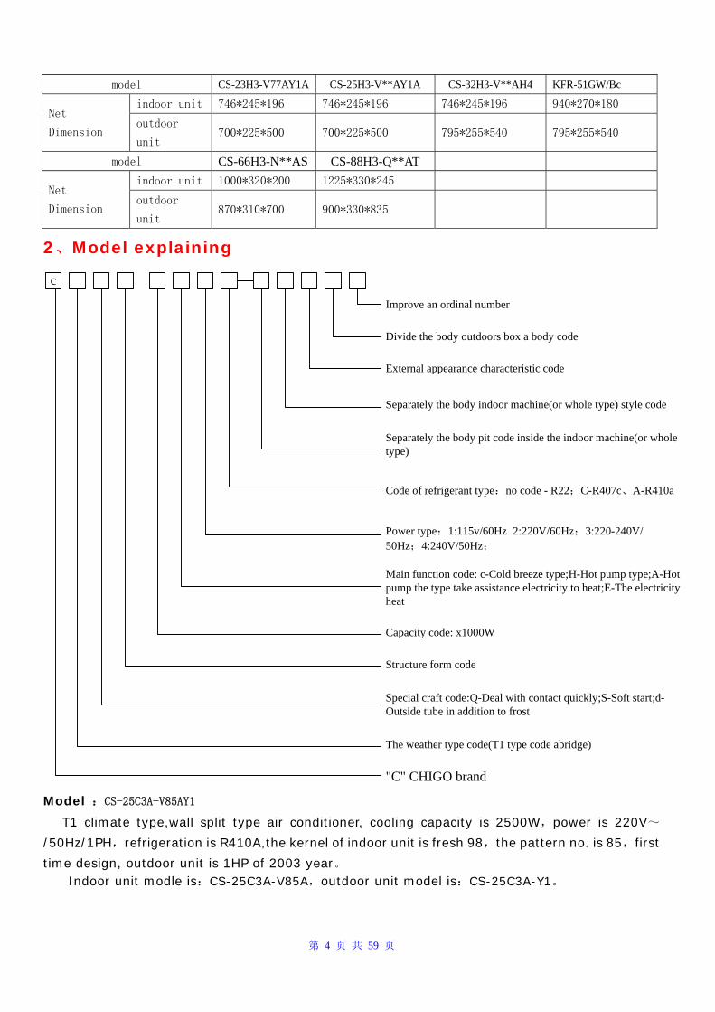
1.2 outdoor unit
CS-23H3-V77AY1A CS-25H3-V**AY1A CS-32H3-V**AH4
KFR-51GW/Bc
CS-66H3-N**AS
CS-88H3-Q**AT
第 4 页 共 59 页
model CS-23H3-V77AY1A CS-25H3-V**AY1A CS-32H3-V**AH4 KFR-51GW/Bc
indoor unit 746*245*196 746*245*196 746*245*196 940*270*180 Net
Dimension outdoor
unit 700*225*500 700*225*500 795*255*540 795*255*540
model CS-66H3-N**AS CS-88H3-Q**AT
indoor unit 1000*320*200 1225*330*245 Net
Dimension outdoor
unit 870*310*700 900*330*835
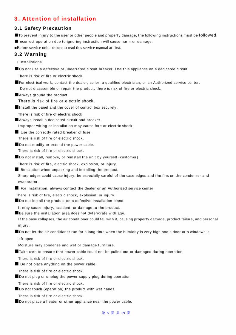
2、Model explaining
c
Improve an ordinal number
Divide the body outdoors box a body code
External appearance characteristic code
Separately the body indoor machine(or whole type) style code
Code of refrigerant type:no code - R22;C-R407c、A-R410a
Power type:1:115v/60Hz 2:220V/60Hz;3:220-240V/50Hz;4:240V/50Hz;
Main function code: c-Cold breeze type;H-Hot pump type;A-Hot pump the type take assistance electricity to heat;E-The electricity heat
Capacity code: x1000W
Separately the body pit code inside the indoor machine(or whole type)
Structure form code
Special craft code:Q-Deal with contact quickly;S-Soft start;d-Outside tube in addition to frost
The weather type code(T1 type code abridge)
"C" CHIGO brand
Model :CS-25C3A-V85AY1 T1 climate type,wall split type air conditioner, cooling capacity is 2500W,power is 220V~
/50Hz/1PH,refrigeration is R410A,the kernel of indoor unit is fresh 98,the pattern no. is 85,first
time design, outdoor unit is 1HP of 2003 year。 Indoor unit modle is:CS-25C3A-V85A,outdoor unit model is:CS-25C3A-Y1。
第 5 页 共 59 页
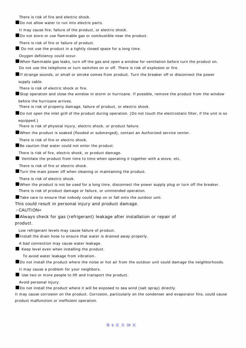
3. Attention of installation
3.1 Safety Precaution ■To prevent injury to the user or other people and property damage, the following instructions must be followed. ■Incorrect operation due to ignoring instruction will cause harm or damage.
■Before service unit, be sure to read this service manual at first.
3.2 Warning
﹥Installation<
■Do not use a defective or underrated circuit breaker. Use this appliance on a dedicated circuit.
There is risk of fire or electric shock.
■For electrical work, contact the dealer, seller, a qualified electrician, or an Authorized service center. Do not disassemble or repair the product, there is risk of fire or electric shock.
■Always ground the product. There is risk of fire or electric shock.
■Install the panel and the cover of control box securely.
There is risk of fire of electric shock.
■Always install a dedicated circuit and breaker.
Improper wiring or installation may cause fore or electric shock.
■ Use the correctly rated breaker of fuse.
There is risk of fire or electric shock.
■Do not modify or extend the power cable.
There is risk of fire or electric shock.
■Do not install, remove, or reinstall the unit by yourself (customer).
There is risk of fire, electric shock, explosion, or injury.
■ Be caution when unpacking and installing the product.
Sharp edges could cause injury, be especially careful of the case edges and the fins on the condenser and
evaporator.
■ For installation, always contact the dealer or an Authorized service center.
There is risk of fire, electric shock, explosion, or injury.
■Do not install the product on a defective installation stand.
It may cause injury, accident, or damage to the product.
■Be sure the installation area does not deteriorate with age.
If the base collapses, the air conditioner could fall with it, causing property damage, product failure, and personal
injury.
■Do not let the air conditioner run for a long time when the humidity is very high and a door or a windows is
left open.
Moisture may condense and wet or damage furniture.
■Take care to ensure that power cable could not be pulled out or damaged during operation.
There is risk of fire or electric shock.
■ Do not place anything on the power cable.
There is risk of fire or electric shock.
■Do not plug or unplug the power supply plug during operation.
There is risk of fire or electric shock.
■Do not touch (operation) the product with wet hands.
There is risk of fire or electric shock.
■Do not place a heater or other appliance near the power cable.
第 6 页 共 59 页
There is risk of fire and electric shock.
■Do not allow water to run into electric parts.
It may cause fire, failure of the product, or electric shock.
■Do not store or use flammable gas or combustible near the product.
There is risk of fire or failure of product.
■ Do not use the product in a tightly closed space for a long time.
Oxygen deficiency could occur.
■When flammable gas leaks, turn off the gas and open a window for ventilation before turn the product on.
Do not use the telephone or turn switches on or off. There is risk of explosion or fire.
■If strange sounds, or small or smoke comes from product. Turn the breaker off or disconnect the power
supply cable.
There is risk of electric shock or fire.
■Stop operation and close the window in storm or hurricane. If possible, remove the product from the window
before the hurricane arrives. There is risk of property damage, failure of product, or electric shock.
■Do not open the inlet grill of the product during operation. (Do not touch the electrostatic filter, if the unit is so
equipped.) There is risk of physical injury, electric shock, or product failure.
■When the product is soaked (flooded or submerged), contact an Authorized service center.
There is risk of fire or electric shock.
■Be caution that water could not enter the product.
There is risk of fire, electric shock, or product damage.
■ Ventilate the product from time to time when operating it together with a stove, etc.
There is risk of fire or electric shock.
■Turn the main power off when cleaning or maintaining the product.
There is risk of electric shock.
■When the product is not be used for a long time, disconnect the power supply plug or turn off the breaker.
There is risk of product damage or failure, or unintended operation.
■Take care to ensure that nobody could step on or fall onto the outdoor unit.
This could result in personal injury and product damage. ﹥CAUTION<
■Always check for gas (refrigerant) leakage after installation or repair of product.
Low refrigerant levels may cause failure of product.
■Install the drain hose to ensure that water is drained away properly.
A bad connection may cause water leakage.
■ Keep level even when installing the product.
To avoid water leakage from vibration。
■Do not install the product where the noise or hot air from the outdoor unit could damage the neighborhoods.
It may cause a problem for your neighbors.
■ Use two or more people to lift and transport the product.
Avoid personal injury.
■Do not install the product where it will be exposed to sea wind (salt spray) directly.
It may cause corrosion on the product. Corrosion, particularly on the condenser and evaporator fins, could cause
product malfunction or inefficient operation.
第 7 页 共 59 页
>Operation < ■Do not expose the skin directly to cool air for long periods of time. (Do not sit in the draft).
This could harm to your health.
■ Do not use the product for special purposes, such as preserving foods, works of art, etc. It is a consumer air
conditioner, not a precision refrigerant system.
There is risk of damage or loss of property.
■ Do not block the inlet or outlet of air flow.
It may cause product failure.
■ Use a soft cloth to clean. Do not use harsh detergents, solvents, etc.
There is risk of fire, electric shock, or damage to the plastic parts of the product.
■ Do not touch the metal parts of the product when removing the air filter. They are very sharp.
There is risk of personal injury.
■ Do not step on pr put anything on the product. (outdoor units)
There is risk of personal injury and failure of product.
■Always insert the filter securely. Clean the filter every two weeks or more often if necessary.
A dirty filter reduces the efficiency of the air conditioner and could cause product malfunction or damage.
■Do not insert hands or other object through air inlet or outlet while the product is operated.
There are sharp and moving parts that could cause personal injury.
■ Do not drink the water drained from the product.
It is not sanitary could cause serious health issues.
■ Use a firm stool or ladder when cleaning or maintaining the product.
Be careful and avoid personal injury.
■ Replace the all batteries in the remote control with new ones of the same type. Do not mix old and mew batteries
or different types of batteries.
There is risk of fire or explosion.
■ Do not recharge or disassemble the batteries. Do not dispose of batteries in a fire.
They may burn of explode.
■ If the liquid from the batteries gets onto your skin or clothes, wash it well with clean water. Do not use the
remote of the batteries have leaked.
The chemical in batteries could cause burns or other health hazards.
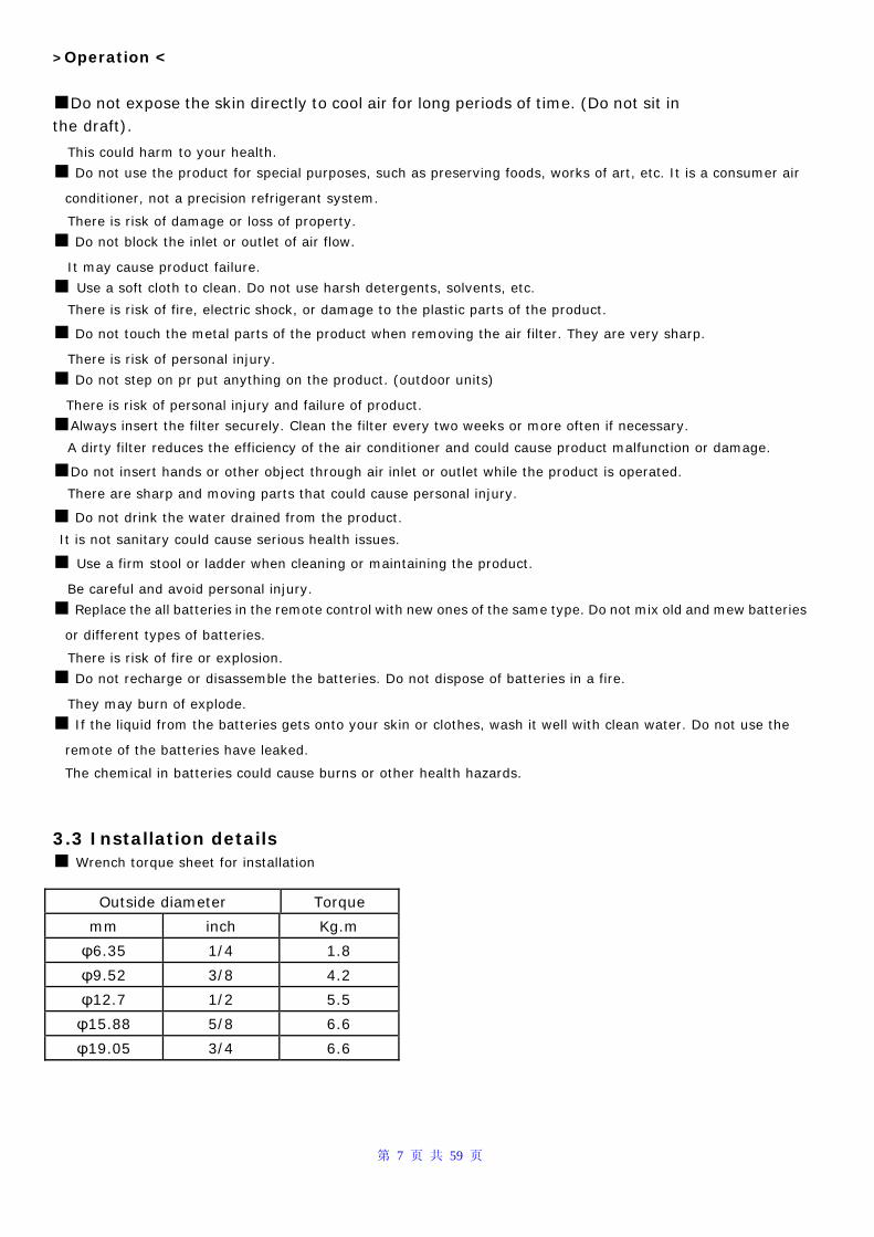
3.3 Installation details ■ Wrench torque sheet for installation
Outside diameter Torque
mm inch Kg.m
φ6.35 1/4 1.8
φ9.52 3/8 4.2
φ12.7 1/2 5.5
φ15.88 5/8 6.6
φ19.05 3/4 6.6
第 8 页 共 59 页
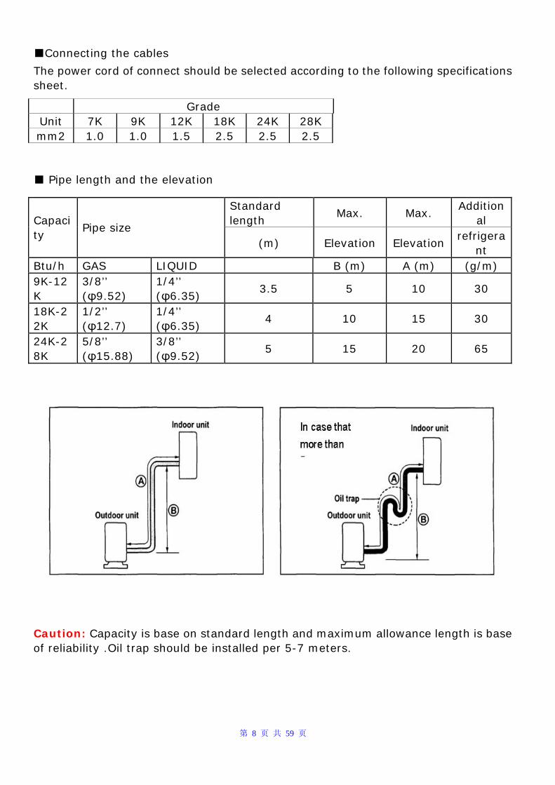
■Connecting the cables
The power cord of connect should be selected according to the following specifications sheet.
Grade Unit 7K 9K 12K 18K 24K 28K mm2 1.0 1.0 1.5 2.5 2.5 2.5 ■ Pipe length and the elevation
Standard length
Max. Max. Addition
al Capacity
Pipe size (m) Elevation Elevation
refrigerant
Btu/h GAS LIQUID B (m) A (m) (g/m) 9K-12K
3/8’’ (φ9.52)
1/4’’ (φ6.35)
3.5 5 10 30
18K-22K
1/2’’ (φ12.7)
1/4’’ (φ6.35)
4 10 15 30
24K-28K
5/8’’ (φ15.88)
3/8’’ (φ9.52)
5 15 20 65
Caution: Capacity is base on standard length and maximum allowance length is base of reliability .Oil trap should be installed per 5-7 meters.
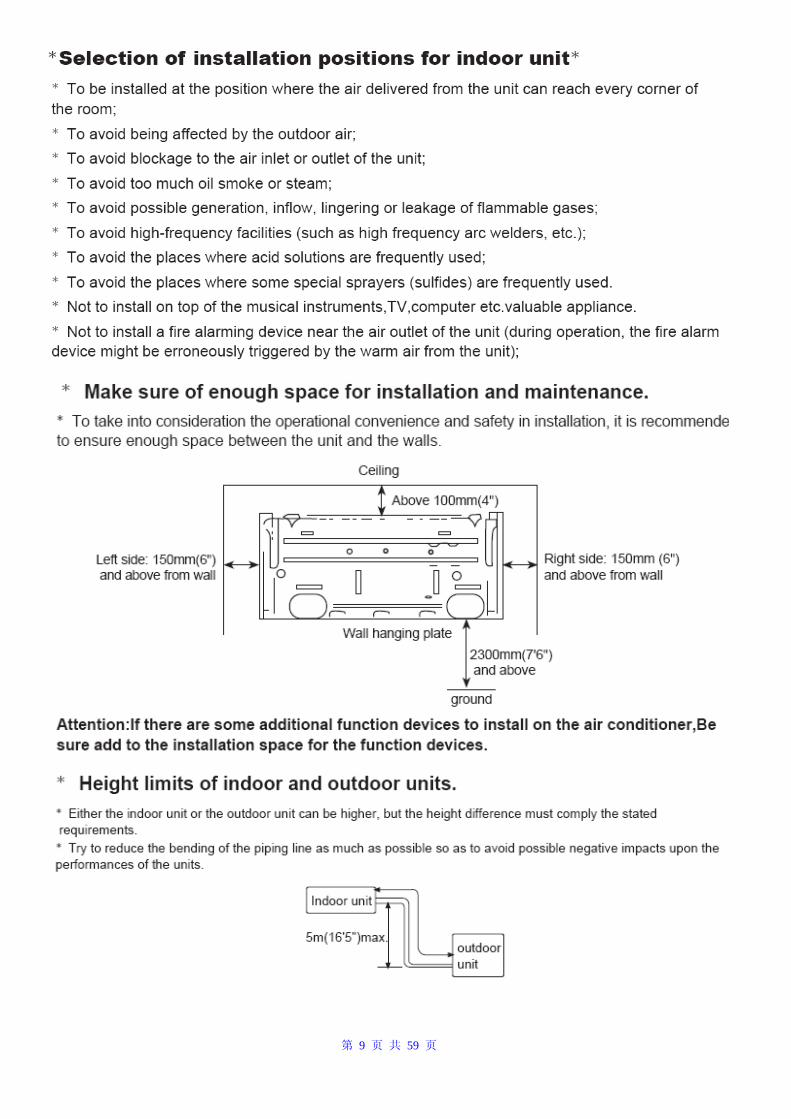
第 9 页 共 59 页
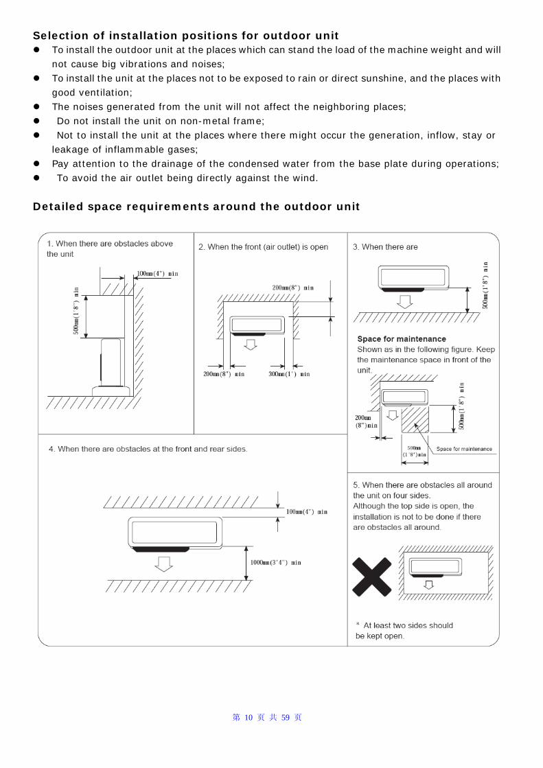
第 10 页 共 59 页
Selection of installation positions for outdoor unit To install the outdoor unit at the places which can stand the load of the machine weight and will
not cause big vibrations and noises; To install the unit at the places not to be exposed to rain or direct sunshine, and the places with
good ventilation; The noises generated from the unit will not affect the neighboring places; Do not install the unit on non-metal frame; Not to install the unit at the places where there might occur the generation, inflow, stay or
leakage of inflammable gases; Pay attention to the drainage of the condensed water from the base plate during operations; To avoid the air outlet being directly against the wind.
Detailed space requirements around the outdoor unit
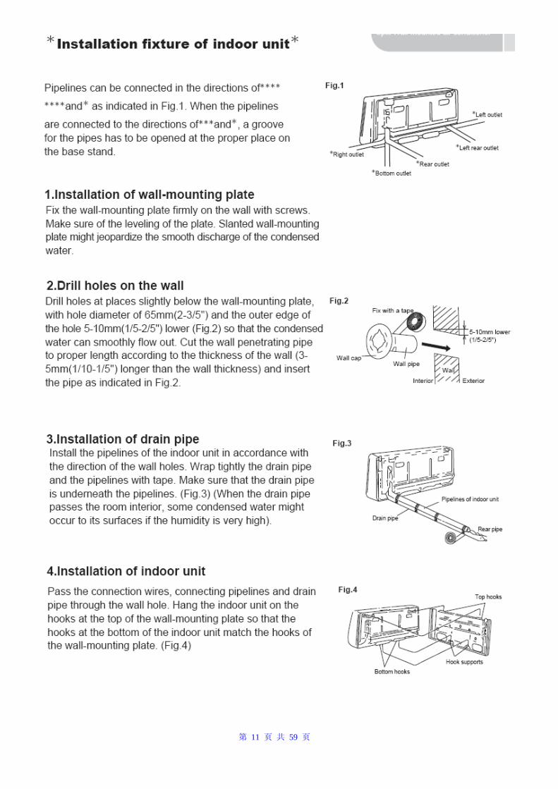
第 11 页 共 59 页
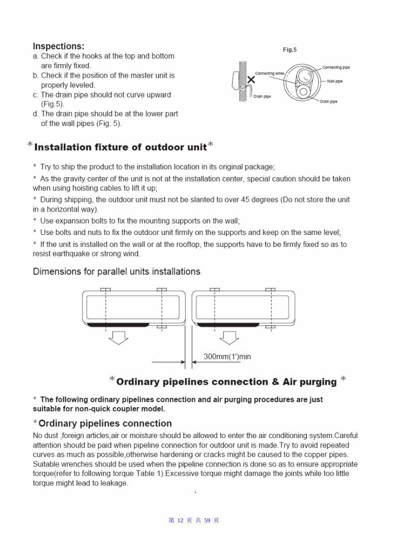
第 12 页 共 59 页
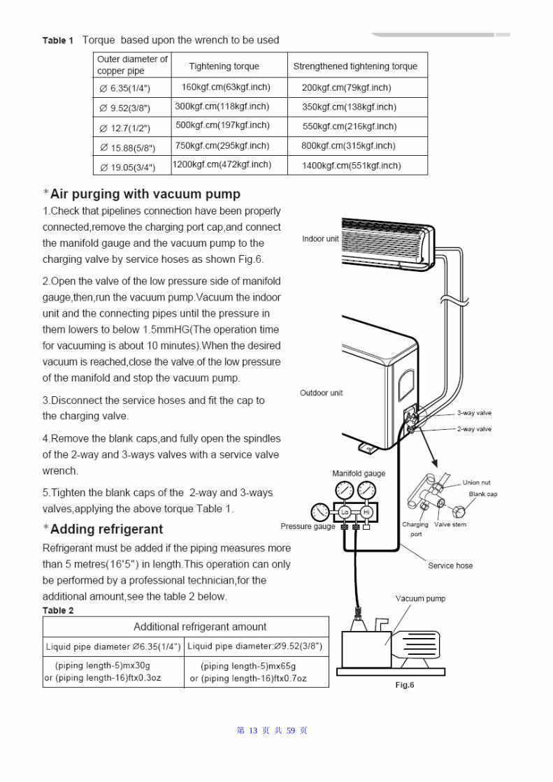
第 13 页 共 59 页
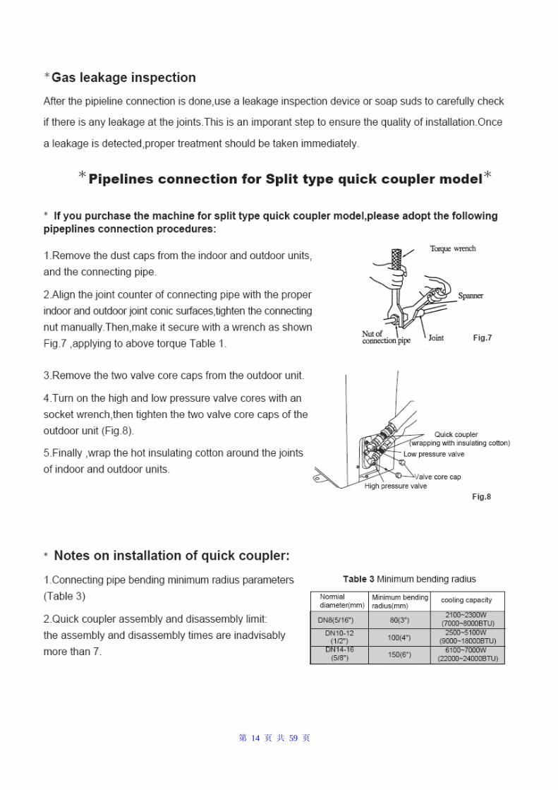
第 14 页 共 59 页
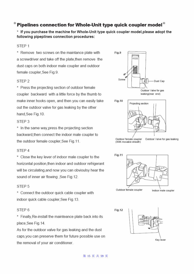
第 15 页 共 59 页
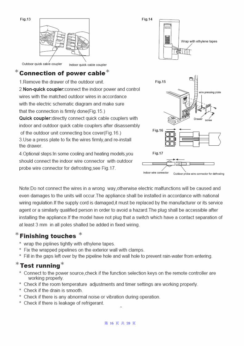
第 16 页 共 59 页
第 17 页 共 59 页
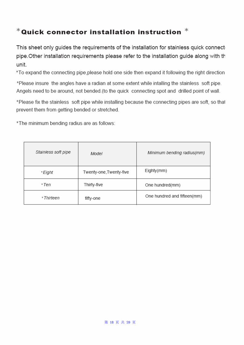
第 18 页 共 59 页
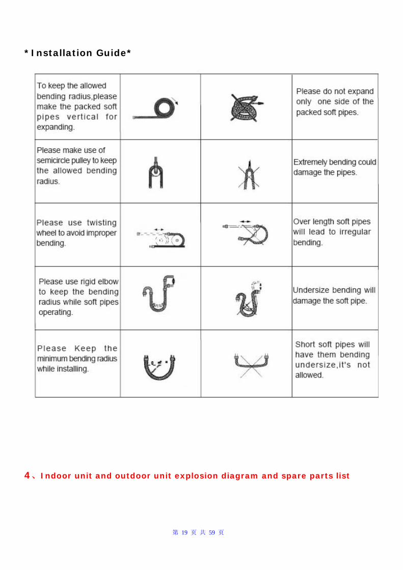
第 19 页 共 59 页
*Installation Guide*
4、Indoor unit and outdoor unit explosion diagram and spare parts list
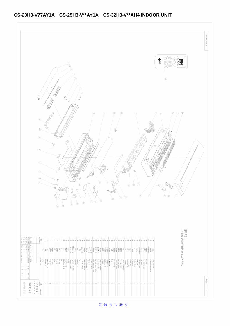
第 20 页 共 59 页
CS-23H3-V77AY1A CS-25H3-V**AY1A CS-32H3-V**AH4 INDOOR UNIT
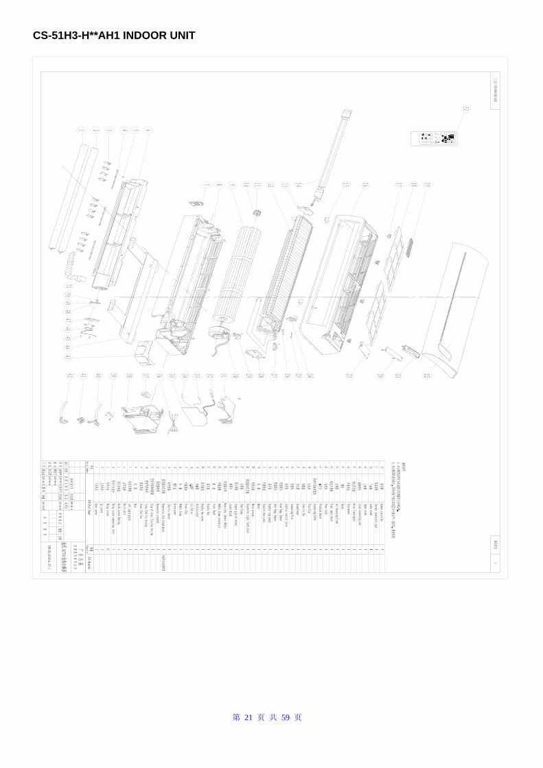
第 21 页 共 59 页
CS-51H3-H**AH1 INDOOR UNIT
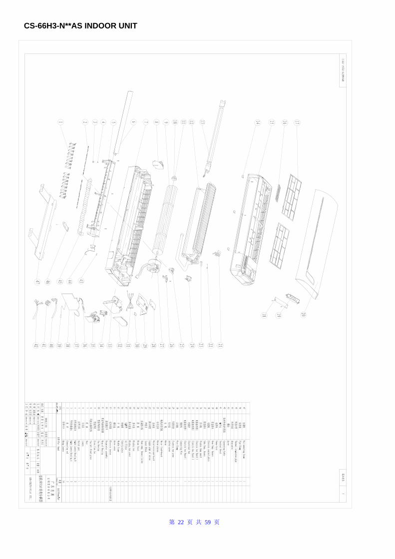
第 22 页 共 59 页
CS-66H3-N**AS INDOOR UNIT
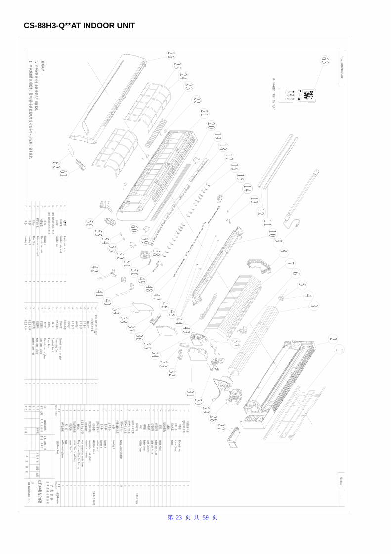
第 23 页 共 59 页
CS-88H3-Q**AT INDOOR UNIT
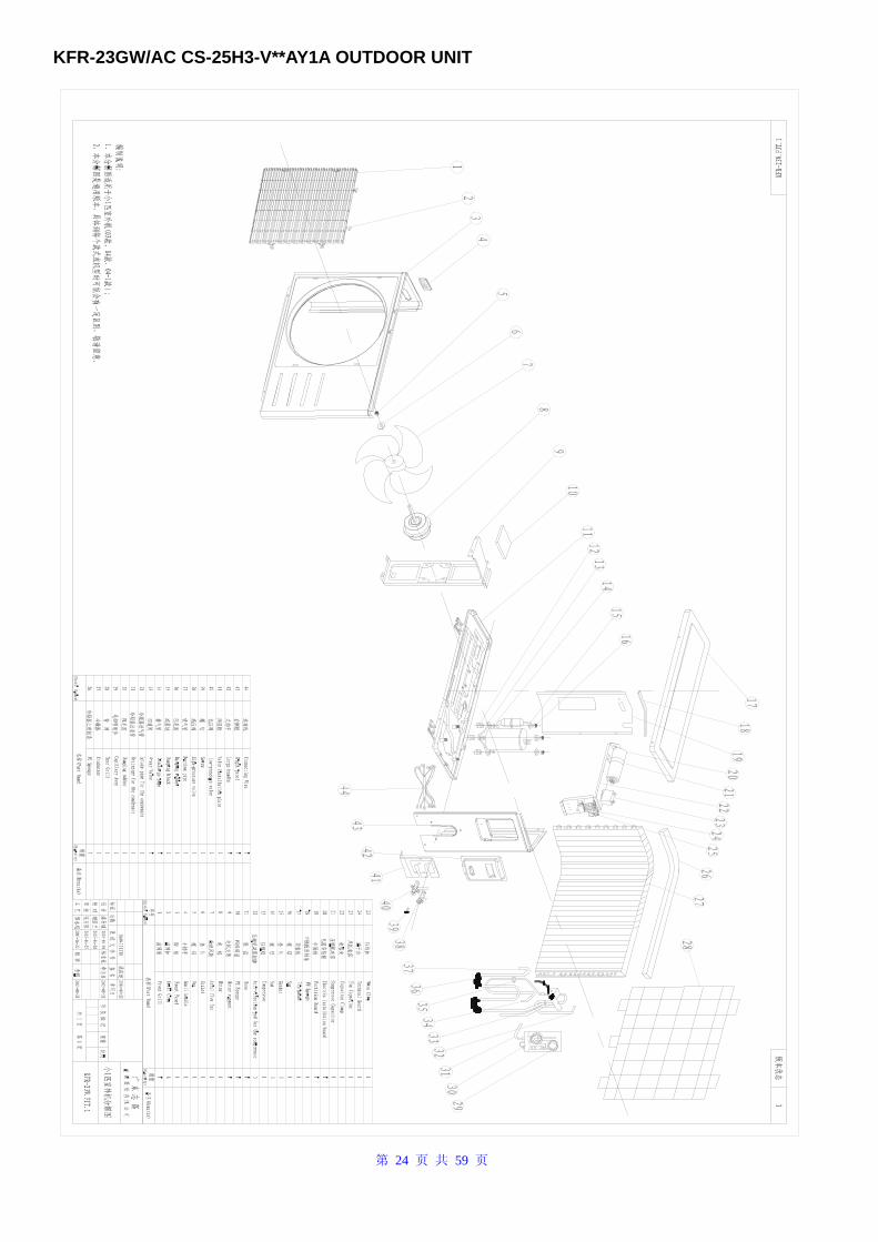
第 24 页 共 59 页
KFR-23GW/AC CS-25H3-V**AY1A OUTDOOR UNIT
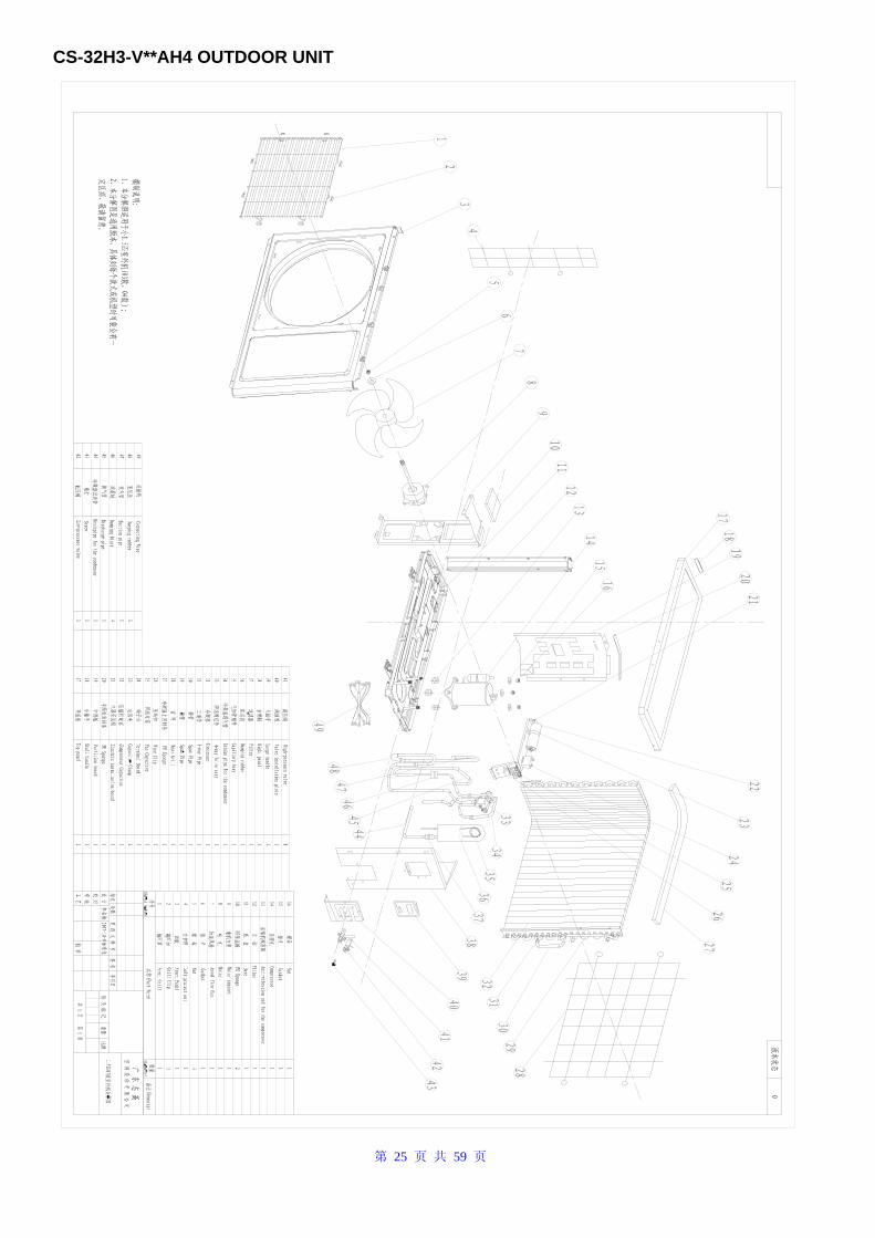
第 25 页 共 59 页
CS-32H3-V**AH4 OUTDOOR UNIT
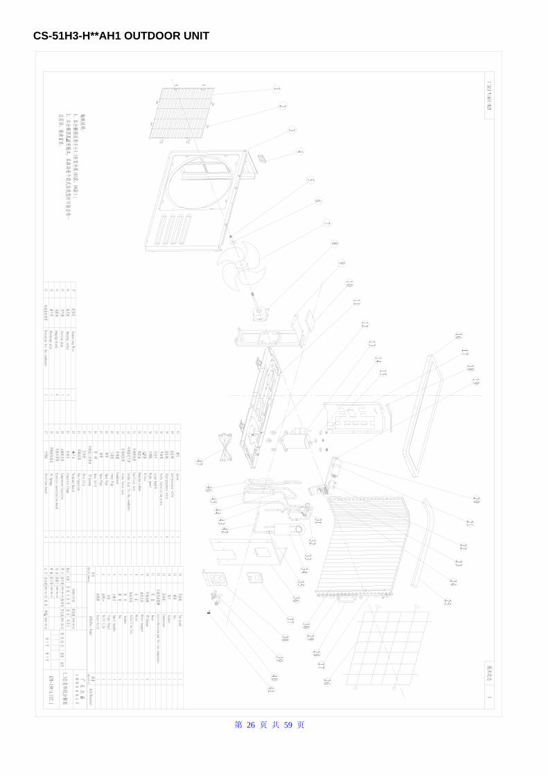
第 26 页 共 59 页
CS-51H3-H**AH1 OUTDOOR UNIT
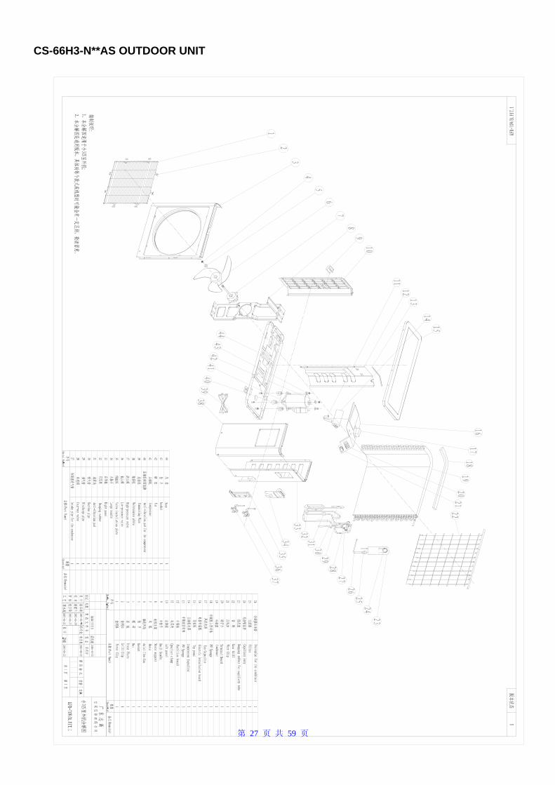
第 27 页 共 59 页
CS-66H3-N**AS OUTDOOR UNIT
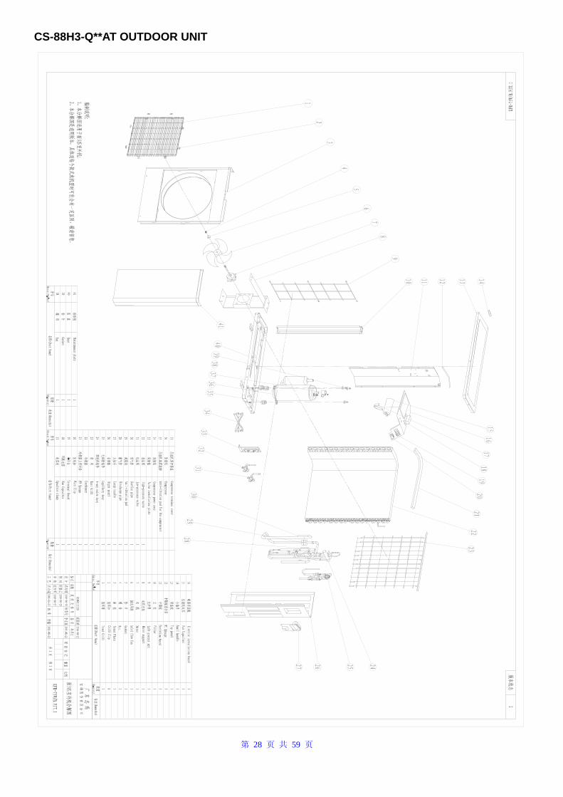
第 28 页 共 59 页
CS-88H3-Q**AT OUTDOOR UNIT
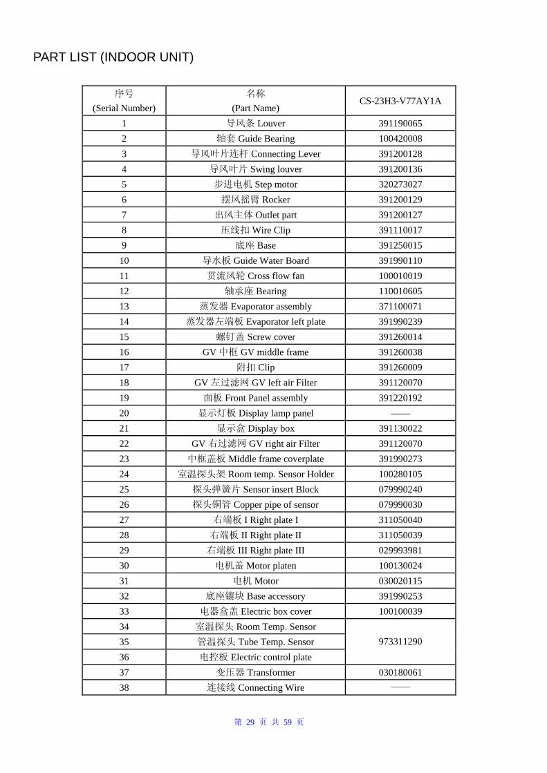
第 29 页 共 59 页
PART LIST (INDOOR UNIT)
序号 (Serial Number)
名称 (Part Name)
CS-23H3-V77AY1A
1 导风条 Louver 391190065 2 轴套 Guide Bearing 100420008 3 导风叶片连杆 Connecting Lever 391200128 4 导风叶片 Swing louver 391200136 5 步进电机 Step motor 320273027 6 摆风摇臂 Rocker 391200129 7 出风主体 Outlet part 391200127 8 压线扣 Wire Clip 391110017 9 底座 Base 391250015
10 导水板 Guide Water Board 391990110 11 贯流风轮 Cross flow fan 100010019 12 轴承座 Bearing 110010605 13 蒸发器 Evaporator assembly 371100071 14 蒸发器左端板 Evaporator left plate 391990239 15 螺钉盖 Screw cover 391260014 16 GV 中框 GV middle frame 391260038 17 附扣 Clip 391260009 18 GV 左过滤网 GV left air Filter 391120070 19 面板 Front Panel assembly 391220192 20 显示灯板 Display lamp panel —— 21 显示盒 Display box 391130022 22 GV 右过滤网 GV right air Filter 391120070 23 中框盖板 Middle frame coverplate 391990273 24 室温探头架 Room temp. Sensor Holder 100280105 25 探头弹簧片 Sensor insert Block 079990240 26 探头铜管 Copper pipe of sensor 079990030 27 右端板 I Right plate I 311050040 28 右端板 II Right plate II 311050039 29 右端板 III Right plate III 029993981 30 电机盖 Motor platen 100130024 31 电机 Motor 030020115 32 底座镶块 Base accessory 391990253 33 电器盒盖 Electric box cover 100100039 34 室温探头 Room Temp. Sensor 35 管温探头 Tube Temp. Sensor 36 电控板 Electric control plate
973311290
37 变压器 Transformer 030180061 38 连接线 Connecting Wire ——
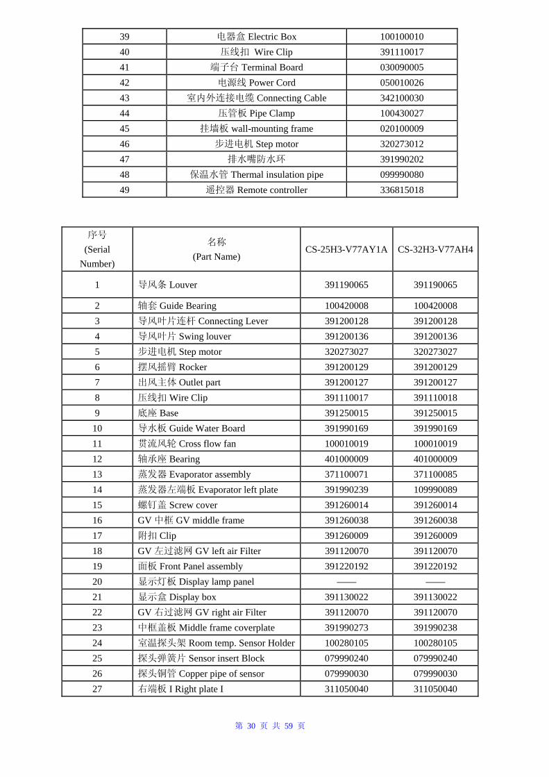
第 30 页 共 59 页
39 电器盒 Electric Box 100100010 40 压线扣 Wire Clip 391110017 41 端子台 Terminal Board 030090005 42 电源线 Power Cord 050010026 43 室内外连接电缆 Connecting Cable 342100030 44 压管板 Pipe Clamp 100430027 45 挂墙板 wall-mounting frame 020100009 46 步进电机 Step motor 320273012 47 排水嘴防水环 391990202 48 保温水管 Thermal insulation pipe 099990080 49 遥控器 Remote controller 336815018
序号 (Serial
Number)
名称 (Part Name)
CS-25H3-V77AY1A CS-32H3-V77AH4
1 导风条 Louver 391190065 391190065
2 轴套 Guide Bearing 100420008 100420008 3 导风叶片连杆 Connecting Lever 391200128 391200128 4 导风叶片 Swing louver 391200136 391200136 5 步进电机 Step motor 320273027 320273027 6 摆风摇臂 Rocker 391200129 391200129 7 出风主体 Outlet part 391200127 391200127 8 压线扣 Wire Clip 391110017 391110018 9 底座 Base 391250015 391250015
10 导水板 Guide Water Board 391990169 391990169 11 贯流风轮 Cross flow fan 100010019 100010019 12 轴承座 Bearing 401000009 401000009 13 蒸发器 Evaporator assembly 371100071 371100085 14 蒸发器左端板 Evaporator left plate 391990239 109990089 15 螺钉盖 Screw cover 391260014 391260014 16 GV 中框 GV middle frame 391260038 391260038 17 附扣 Clip 391260009 391260009 18 GV 左过滤网 GV left air Filter 391120070 391120070 19 面板 Front Panel assembly 391220192 391220192 20 显示灯板 Display lamp panel —— —— 21 显示盒 Display box 391130022 391130022 22 GV 右过滤网 GV right air Filter 391120070 391120070 23 中框盖板 Middle frame coverplate 391990273 391990238 24 室温探头架 Room temp. Sensor Holder 100280105 100280105 25 探头弹簧片 Sensor insert Block 079990240 079990240 26 探头铜管 Copper pipe of sensor 079990030 079990030 27 右端板 I Right plate I 311050040 311050040
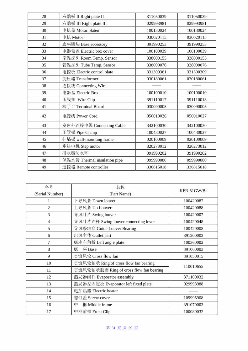
第 31 页 共 59 页
28 右端板 II Right plate II 311050039 311050039 29 右端板 III Right plate III 029993981 029993981 30 电机盖 Motor platen 100130024 100130024 31 电机 Motor 030020115 030020115 32 底座镶块 Base accessory 391990253 391990253 33 电器盒盖 Electric box cover 100100039 100100039 34 室温探头 Room Temp. Sensor 338000155 338000155 35 管温探头 Tube Temp. Sensor 338000076 338000076 36 电控板 Electric control plate 331300361 331300309 37 变压器 Transformer 030180061 030180061 38 连接线 Connecting Wire —— ——
39 电器盒 Electric Box 100100010 100100010 40 压线扣 Wire Clip 391110017 391110018 41 端子台 Terminal Board 030090005 030090005
42 电源线 Power Cord 050010026 050010027
43 室内外连接电缆 Connecting Cable 342100030 342100030 44 压管板 Pipe Clamp 100430027 100430027 45 挂墙板 wall-mounting frame 020100009 020100009 46 步进电机 Step motor 320273012 320273012 47 排水嘴防水环 391990202 391990202 48 保温水管 Thermal insulation pipe 099990080 099990080 49 遥控器 Remote controller 336815018 336815018
序号 (Serial Number)
名称 (Part Name)
KFR-51GW/Bc
1 下导风条 Down louver 100420087 2 上导风条 Up Louver 100420088 3 导风叶片 Swing louver 100420007 4 导风叶片连杆 Swing louver connecting lever 100420048 5 导风条轴套 Guide Louver Bearing 100420008 6 出风主体 Outlet part 391200003 7 底座左角板 Left angle plate 100360002 8 底 座 Base 391060003 9 贯流风轮 Cross flow fan 391050015
10 贯流风轮轴承 Ring of cross flow fan bearing 11 贯流风轮轴承胶圈 Ring of cross flow fan bearing
110010655
12 蒸发器组件 Evaporator assembly 371100032 13 蒸发器左固定板 Evaporator left fixed plate 029993988 14 电加热器 Electric heater —— 15 螺钉盖 Screw cover 109995908 16 中 框 Middle frame 391070003 17 中框前扣 Front Clip 100080032
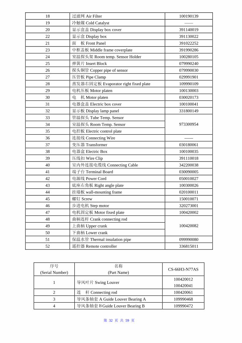
第 32 页 共 59 页
18 过滤网 Air Filter 100190139 19 冷触媒 Cold Catalyst —— 20 显示盒盖 Display box cover 391140019 22 显示盒 Display box 391130022 21 面 板 Front Panel 391022252 23 中框盖板 Middle frame coverplate 391990286 24 室温探头架 Room temp. Sensor Holder 100280105 25 弹簧片 Insert Block 079990240 26 探头铜管 Copper pipe of sensor 079990030 27 压管板 Pipe Clamp 029991901 28 蒸发器右固定板 Evaporator right fixed plate 109990109 29 电机压板 Motor platen 100130003 30 电 机 Motor platen 030020173 31 电器盒盖 Electric box cover 100100041 32 显示板 Display lamp panel 331800149 33 管温探头 Tube Temp. Sensor 34 室温探头 Room Temp. Sensor 35 电控板 Electric control plate
973300954
36 连接线 Connecting Wire —— 37 变压器 Transformer 030180061 38 电器盒 Electric Box 100100035 39 压线扣 Wire Clip 391110018 40 室内外连接电缆线 Connecting Cable 342200038 41 端子台 Terminal Board 030090005 42 电源线 Power Cord 050010027 43 底座右角板 Right angle plate 100300026 44 挂墙板 wall-mounting frame 020100011 45 螺钉 Screw 150010071 46 步进电机 Step motor 320273001 47 电机固定板 Motor fixed plate 100420002 48 曲柄连杆 Crank connecting rod 49 上曲柄 Upper crank 50 下曲柄 Lower crank
100420082
51 保温水管 Thermal insulation pipe 099990080 52 遥控器 Remote controller 336815011
序号 (Serial Number)
名称 (Part Name)
CS-66H3-N77AS
1 导风叶片 Swing Louver 100420012 100420041
2 连 杆 Connecting rod 100420061 3 导风条轴套 A Guide Louver Bearing A 109990468 4 导风条轴套BGuide Louver Bearing B 109990472
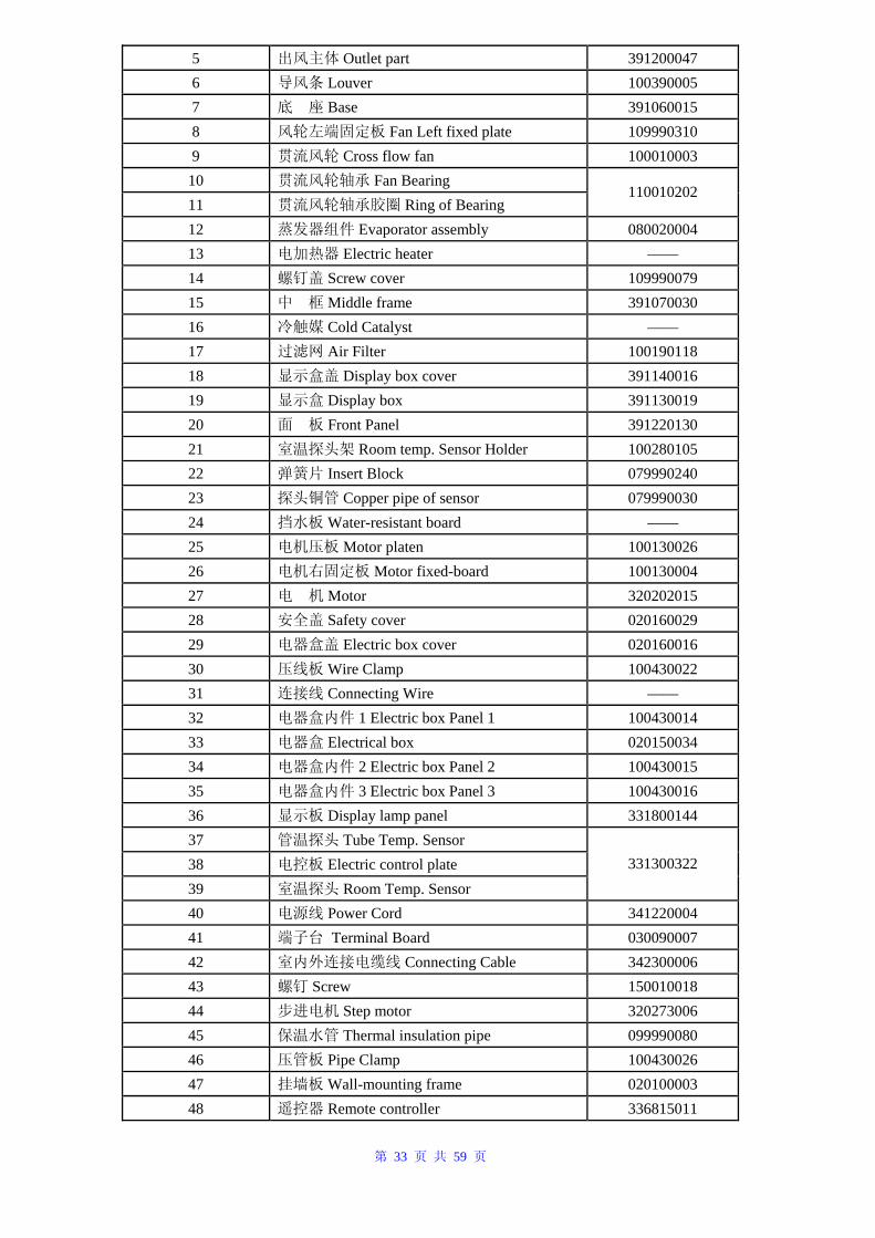
第 33 页 共 59 页
5 出风主体 Outlet part 391200047 6 导风条 Louver 100390005 7 底 座 Base 391060015 8 风轮左端固定板 Fan Left fixed plate 109990310 9 贯流风轮 Cross flow fan 100010003
10 贯流风轮轴承 Fan Bearing 11 贯流风轮轴承胶圈 Ring of Bearing
110010202
12 蒸发器组件 Evaporator assembly 080020004 13 电加热器 Electric heater —— 14 螺钉盖 Screw cover 109990079 15 中 框 Middle frame 391070030 16 冷触媒 Cold Catalyst —— 17 过滤网 Air Filter 100190118 18 显示盒盖 Display box cover 391140016 19 显示盒 Display box 391130019 20 面 板 Front Panel 391220130 21 室温探头架 Room temp. Sensor Holder 100280105 22 弹簧片 Insert Block 079990240 23 探头铜管 Copper pipe of sensor 079990030 24 挡水板 Water-resistant board —— 25 电机压板 Motor platen 100130026 26 电机右固定板 Motor fixed-board 100130004 27 电 机 Motor 320202015 28 安全盖 Safety cover 020160029 29 电器盒盖 Electric box cover 020160016 30 压线板 Wire Clamp 100430022 31 连接线 Connecting Wire —— 32 电器盒内件 1 Electric box Panel 1 100430014 33 电器盒 Electrical box 020150034 34 电器盒内件 2 Electric box Panel 2 100430015 35 电器盒内件 3 Electric box Panel 3 100430016 36 显示板 Display lamp panel 331800144 37 管温探头 Tube Temp. Sensor 38 电控板 Electric control plate 39 室温探头 Room Temp. Sensor
331300322
40 电源线 Power Cord 341220004 41 端子台 Terminal Board 030090007 42 室内外连接电缆线 Connecting Cable 342300006 43 螺钉 Screw 150010018 44 步进电机 Step motor 320273006 45 保温水管 Thermal insulation pipe 099990080 46 压管板 Pipe Clamp 100430026 47 挂墙板 Wall-mounting frame 020100003 48 遥控器 Remote controller 336815011
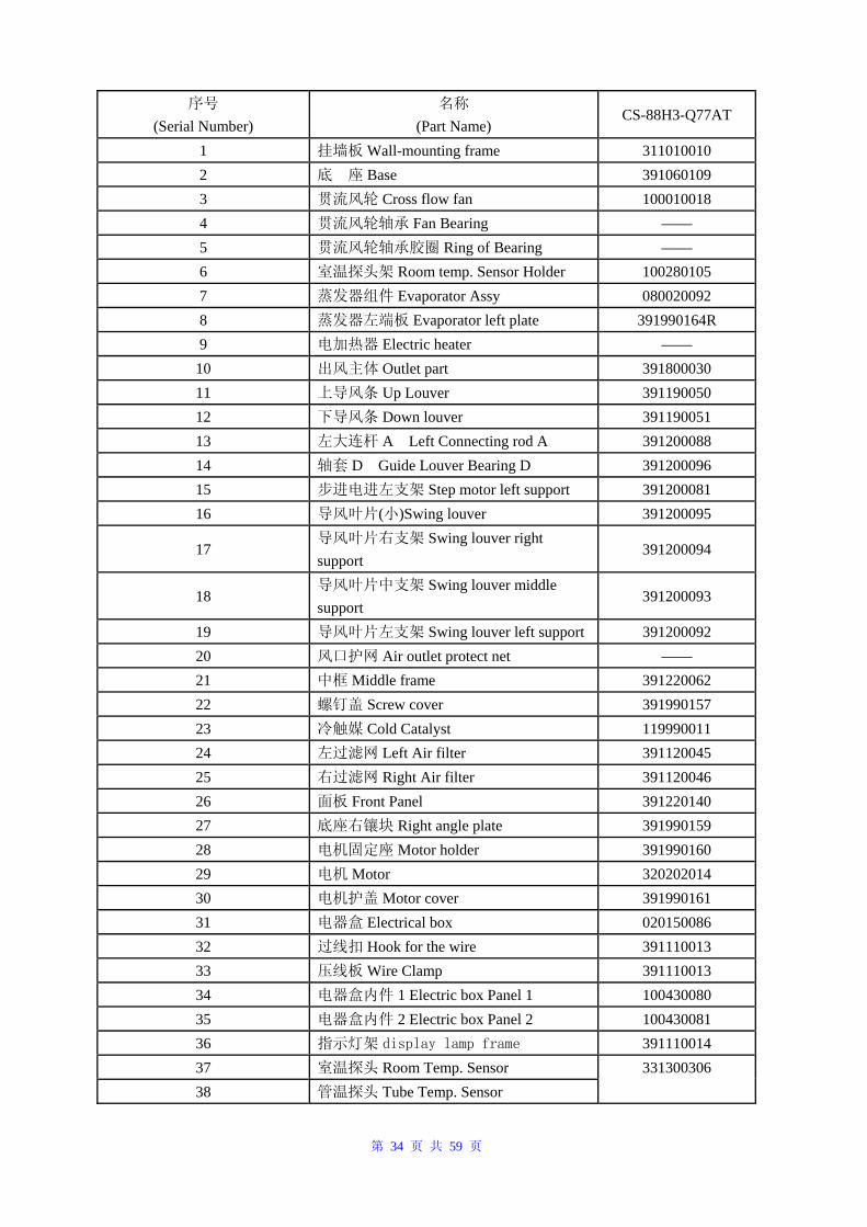
第 34 页 共 59 页
序号 (Serial Number)
名称 (Part Name)
CS-88H3-Q77AT
1 挂墙板 Wall-mounting frame 311010010 2 底 座 Base 391060109 3 贯流风轮 Cross flow fan 100010018 4 贯流风轮轴承 Fan Bearing —— 5 贯流风轮轴承胶圈 Ring of Bearing —— 6 室温探头架 Room temp. Sensor Holder 100280105 7 蒸发器组件 Evaporator Assy 080020092 8 蒸发器左端板 Evaporator left plate 391990164R 9 电加热器 Electric heater ——
10 出风主体 Outlet part 391800030 11 上导风条 Up Louver 391190050 12 下导风条 Down louver 391190051 13 左大连杆 A Left Connecting rod A 391200088 14 轴套 D Guide Louver Bearing D 391200096 15 步进电进左支架 Step motor left support 391200081 16 导风叶片(小)Swing louver 391200095
17 导风叶片右支架 Swing louver right support
391200094
18 导风叶片中支架 Swing louver middle support
391200093
19 导风叶片左支架 Swing louver left support 391200092 20 风口护网 Air outlet protect net —— 21 中框 Middle frame 391220062 22 螺钉盖 Screw cover 391990157 23 冷触媒 Cold Catalyst 119990011 24 左过滤网 Left Air filter 391120045 25 右过滤网 Right Air filter 391120046 26 面板 Front Panel 391220140 27 底座右镶块 Right angle plate 391990159 28 电机固定座 Motor holder 391990160 29 电机 Motor 320202014 30 电机护盖 Motor cover 391990161 31 电器盒 Electrical box 020150086 32 过线扣 Hook for the wire 391110013 33 压线板 Wire Clamp 391110013 34 电器盒内件 1 Electric box Panel 1 100430080 35 电器盒内件 2 Electric box Panel 2 100430081 36 指示灯架 display lamp frame 391110014 37 室温探头 Room Temp. Sensor 38 管温探头 Tube Temp. Sensor
331300306
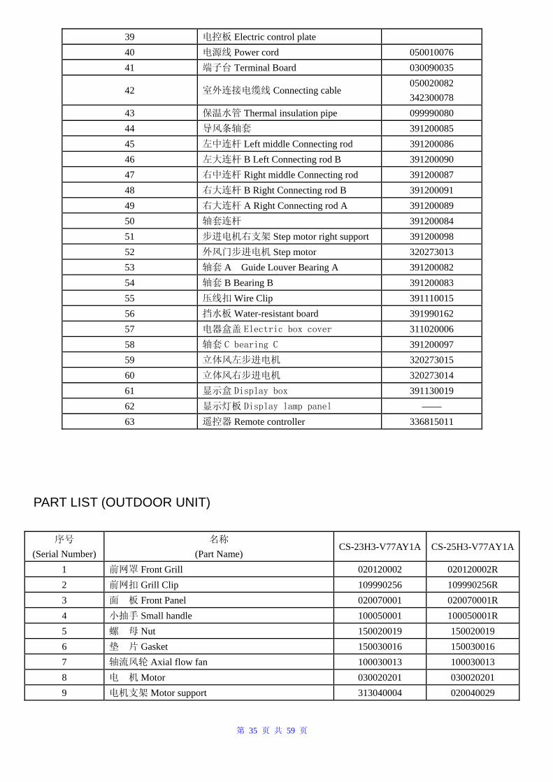
第 35 页 共 59 页
39 电控板 Electric control plate 40 电源线 Power cord 050010076 41 端子台 Terminal Board 030090035
42 室外连接电缆线 Connecting cable 050020082 342300078
43 保温水管 Thermal insulation pipe 099990080 44 导风条轴套 391200085 45 左中连杆 Left middle Connecting rod 391200086 46 左大连杆 B Left Connecting rod B 391200090 47 右中连杆 Right middle Connecting rod 391200087 48 右大连杆 B Right Connecting rod B 391200091 49 右大连杆 A Right Connecting rod A 391200089 50 轴套连杆 391200084 51 步进电机右支架 Step motor right support 391200098 52 外风门步进电机 Step motor 320273013 53 轴套 A Guide Louver Bearing A 391200082 54 轴套 B Bearing B 391200083 55 压线扣 Wire Clip 391110015 56 挡水板 Water-resistant board 391990162 57 电器盒盖 Electric box cover 311020006 58 轴套 C bearing C 391200097 59 立体风左步进电机 320273015 60 立体风右步进电机 320273014 61 显示盒 Display box 391130019 62 显示灯板 Display lamp panel —— 63 遥控器 Remote controller 336815011
PART LIST (OUTDOOR UNIT)
序号 (Serial Number)
名称 (Part Name)
CS-23H3-V77AY1A CS-25H3-V77AY1A
1 前网罩 Front Grill 020120002 020120002R 2 前网扣 Grill Clip 109990256 109990256R 3 面 板 Front Panel 020070001 020070001R 4 小抽手 Small handle 100050001 100050001R 5 螺 母 Nut 150020019 150020019 6 垫 片 Gasket 150030016 150030016 7 轴流风轮 Axial flow fan 100030013 100030013 8 电 机 Motor 030020201 030020201 9 电机支架 Motor support 313040004 020040029
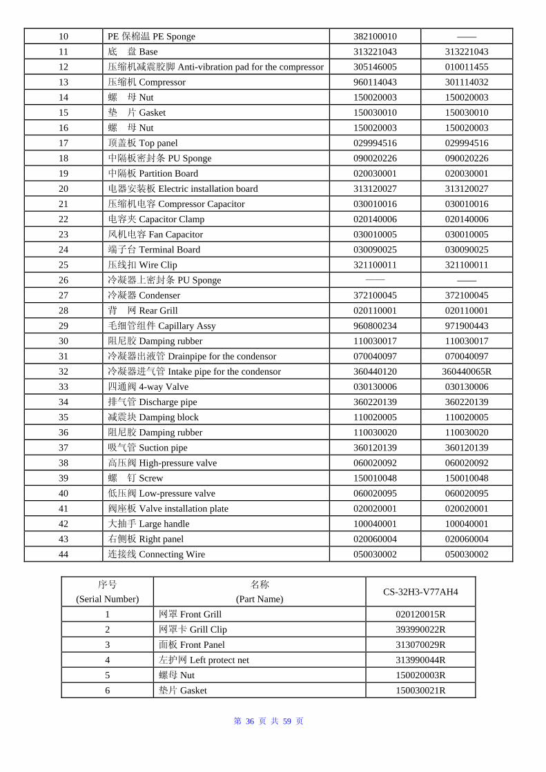
第 36 页 共 59 页
10 PE 保棉温 PE Sponge 382100010 —— 11 底 盘 Base 313221043 313221043 12 压缩机减震胶脚 Anti-vibration pad for the compressor 305146005 010011455 13 压缩机 Compressor 960114043 301114032 14 螺 母 Nut 150020003 150020003 15 垫 片 Gasket 150030010 150030010 16 螺 母 Nut 150020003 150020003 17 顶盖板 Top panel 029994516 029994516 18 中隔板密封条 PU Sponge 090020226 090020226 19 中隔板 Partition Board 020030001 020030001 20 电器安装板 Electric installation board 313120027 313120027 21 压缩机电容 Compressor Capacitor 030010016 030010016 22 电容夹 Capacitor Clamp 020140006 020140006 23 风机电容 Fan Capacitor 030010005 030010005 24 端子台 Terminal Board 030090025 030090025 25 压线扣 Wire Clip 321100011 321100011 26 冷凝器上密封条 PU Sponge —— —— 27 冷凝器 Condenser 372100045 372100045 28 背 网 Rear Grill 020110001 020110001 29 毛细管组件 Capillary Assy 960800234 971900443 30 阻尼胶 Damping rubber 110030017 110030017 31 冷凝器出液管 Drainpipe for the condensor 070040097 070040097 32 冷凝器进气管 Intake pipe for the condensor 360440120 360440065R 33 四通阀 4-way Valve 030130006 030130006 34 排气管 Discharge pipe 360220139 360220139 35 减震块 Damping block 110020005 110020005 36 阻尼胶 Damping rubber 110030020 110030020 37 吸气管 Suction pipe 360120139 360120139 38 高压阀 High-pressure valve 060020092 060020092 39 螺 钉 Screw 150010048 150010048 40 低压阀 Low-pressure valve 060020095 060020095 41 阀座板 Valve installation plate 020020001 020020001 42 大抽手 Large handle 100040001 100040001 43 右侧板 Right panel 020060004 020060004 44 连接线 Connecting Wire 050030002 050030002
序号
(Serial Number) 名称
(Part Name) CS-32H3-V77AH4
1 网罩 Front Grill 020120015R 2 网罩卡 Grill Clip 393990022R 3 面板 Front Panel 313070029R 4 左护网 Left protect net 313990044R 5 螺母 Nut 150020003R 6 垫片 Gasket 150030021R
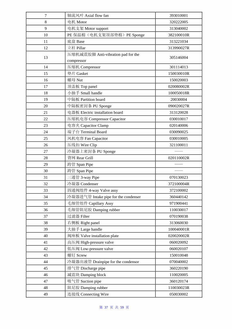
第 37 页 共 59 页
7 轴流风叶 Axial flow fan 393010001 8 电机 Motor 320222005 9 电机支架 Motor support 313040002
10 PE 保温棉(电机支架顶部垫棉)PE Sponge 382100010R 11 底盘 Base 313221034 12 立柱 Pillar 313990027R
13 压缩机减震胶脚 Anti-vibration pad for the compressor
305146004
14 压缩机 Compressor 301114013 15 垫片 Gasket 150030010R 16 螺母 Nut 150020003 17 顶盖板 Top panel 020080002R 18 小抽手 Small handle 100050018R 19 中隔板 Partition board 20030004 20 中隔板密封条 PU Sponge 090020027R 21 电器板 Electric installation board 313120028 22 压缩机电容 Compressor Capacitor 030010017 23 电容夹 Capacitor Clamp 020140006 24 端子台 Terminal Board 030090025 25 风机电容 Fan Capacitor 030010005 26 压线扣 Wire Clip 321100011 27 冷凝器上密封条 PU Sponge ——
28 背网 Rear Grill 020110002R 29 跨管 Span Pipe ——
30 跨管 Span Pipe ——
31 三通管 3-way Pipe 070130023 32 冷凝器 Condenser 372100004R 33 四通阀组件 4-way Valve assy 372100002 34 冷凝器进气管 Intake pipe for the condenser 360440142 35 毛细管组件 Capillary Assy 971900441 36 毛细管阻尼胶 Damping rubber 110030017 37 过滤器 Filter 070190038 38 右侧板 Right panel 313060030 39 大抽手 Large handle 100040001R 40 阀座板 Valve installation plate 020020002R 41 高压阀 High-pressure valve 060020092 42 低压阀 Low-pressure valve 060020107 43 螺钉 Screw 150010048 44 冷凝器出液管 Drainpipe for the condensor 070040002 45 排气管 Discharge pipe 360220190 46 减震块 Damping block 110020005 47 吸气管 Suction pipe 360120174 48 阻尼胶 Damping rubber 110030023R 49 连接线 Connecting Wire 050030002
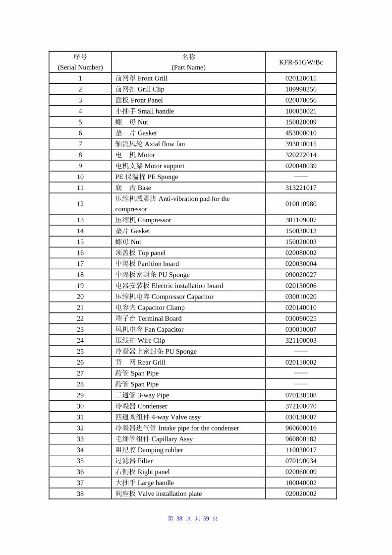
第 38 页 共 59 页
序号 (Serial Number)
名称 (Part Name)
KFR-51GW/Bc
1 前网罩 Front Grill 020120015 2 前网扣 Grill Clip 109990256 3 面板 Front Panel 020070056 4 小抽手 Small handle 100050021 5 螺 母 Nut 150020009 6 垫 片 Gasket 453000010 7 轴流风轮 Axial flow fan 393010015 8 电 机 Motor 320222014 9 电机支架 Motor support 020040039
10 PE 保温棉 PE Sponge —— 11 底 盘 Base 313221017
12 压缩机减震脚 Anti-vibration pad for the compressor
010010980
13 压缩机 Compressor 301109007 14 垫片 Gasket 150030013 15 螺母 Nut 150020003 16 顶盖板 Top panel 020080002 17 中隔板 Partition board 020030004 18 中隔板密封条 PU Sponge 090020027 19 电器安装板 Electric installation board 020130006 20 压缩机电容 Compressor Capacitor 030010020 21 电容夹 Capacitor Clamp 020140010 22 端子台 Terminal Board 030090025 23 风机电容 Fan Capacitor 030010007 24 压线扣 Wire Clip 321100003 25 冷凝器上密封条 PU Sponge —— 26 背 网 Rear Grill 020110002 27 跨管 Span Pipe —— 28 跨管 Span Pipe —— 29 三通管 3-way Pipe 070130108 30 冷凝器 Condenser 372100070 31 四通阀组件 4-way Valve assy 030130007 32 冷凝器进气管 Intake pipe for the condenser 960600016 33 毛细管组件 Capillary Assy 960800182 34 阻尼胶 Damping rubber 110030017 35 过滤器 Filter 070190034 36 右侧板 Right panel 020060009 37 大抽手 Large handle 100040002 38 阀座板 Valve installation plate 020020002
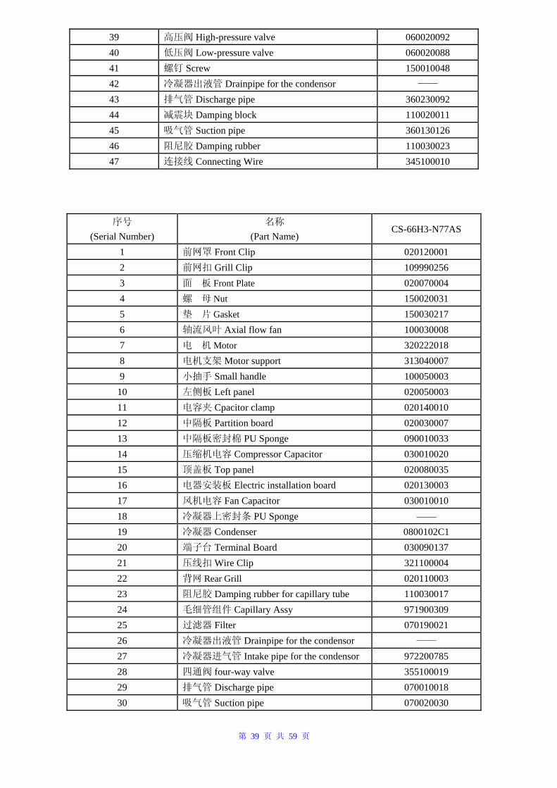
第 39 页 共 59 页
39 高压阀 High-pressure valve 060020092 40 低压阀 Low-pressure valve 060020088 41 螺钉 Screw 150010048 42 冷凝器出液管 Drainpipe for the condensor —— 43 排气管 Discharge pipe 360230092 44 减震块 Damping block 110020011 45 吸气管 Suction pipe 360130126 46 阻尼胶 Damping rubber 110030023 47 连接线 Connecting Wire 345100010
序号 (Serial Number)
名称 (Part Name)
CS-66H3-N77AS
1 前网罩 Front Clip 020120001 2 前网扣 Grill Clip 109990256 3 面 板 Front Plate 020070004 4 螺 母 Nut 150020031 5 垫 片 Gasket 150030217 6 轴流风叶 Axial flow fan 100030008 7 电 机 Motor 320222018 8 电机支架 Motor support 313040007 9 小抽手 Small handle 100050003
10 左侧板 Left panel 020050003 11 电容夹 Cpacitor clamp 020140010 12 中隔板 Partition board 020030007 13 中隔板密封棉 PU Sponge 090010033 14 压缩机电容 Compressor Capacitor 030010020 15 顶盖板 Top panel 020080035 16 电器安装板 Electric installation board 020130003 17 风机电容 Fan Capacitor 030010010 18 冷凝器上密封条 PU Sponge —— 19 冷凝器 Condenser 0800102C1 20 端子台 Terminal Board 030090137 21 压线扣 Wire Clip 321100004 22 背网 Rear Grill 020110003 23 阻尼胶 Damping rubber for capillary tube 110030017 24 毛细管组件 Capillary Assy 971900309 25 过滤器 Filter 070190021 26 冷凝器出液管 Drainpipe for the condensor ——
27 冷凝器进气管 Intake pipe for the condensor 972200785 28 四通阀 four-way valve 355100019 29 排气管 Discharge pipe 070010018 30 吸气管 Suction pipe 070020030
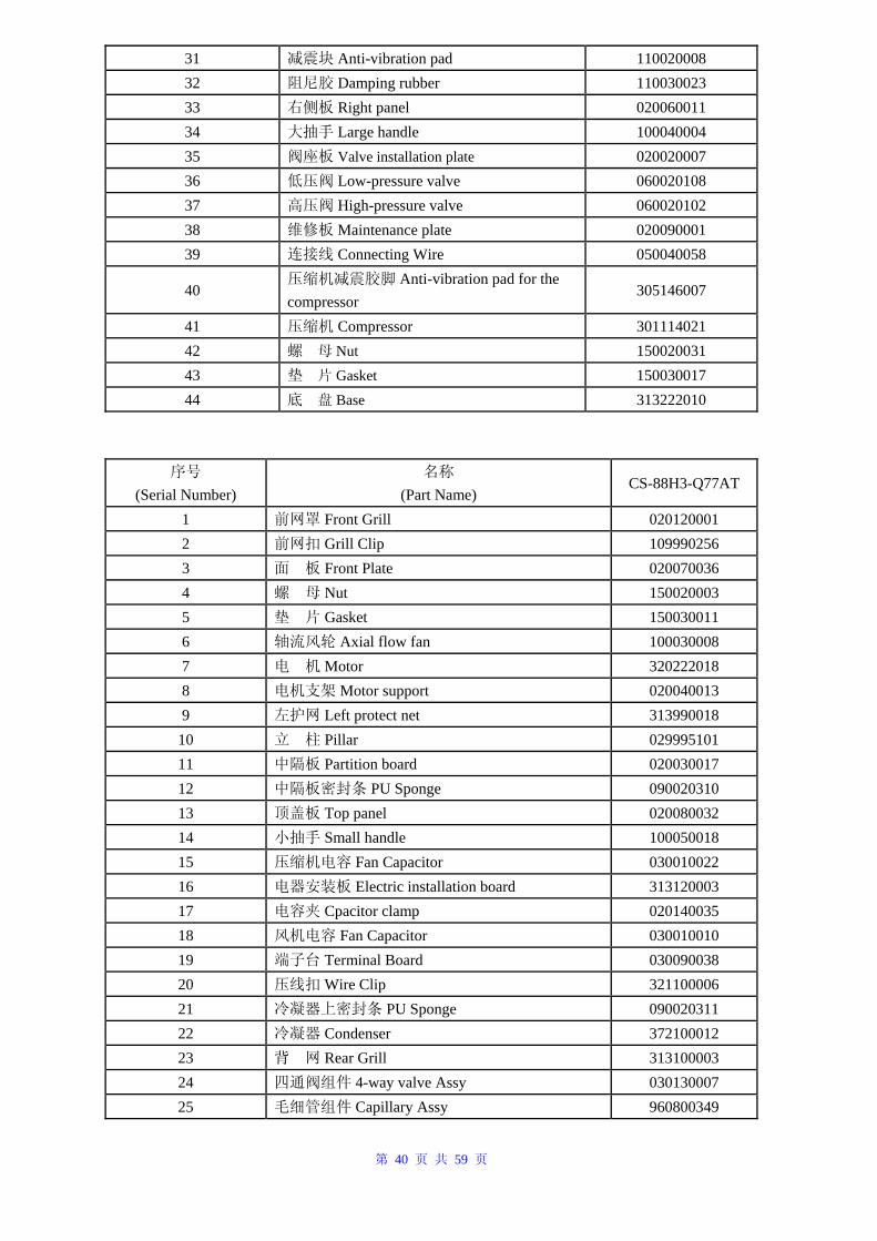
第 40 页 共 59 页
31 减震块 Anti-vibration pad 110020008 32 阻尼胶 Damping rubber 110030023 33 右侧板 Right panel 020060011 34 大抽手 Large handle 100040004 35 阀座板 Valve installation plate 020020007 36 低压阀 Low-pressure valve 060020108 37 高压阀 High-pressure valve 060020102 38 维修板 Maintenance plate 020090001 39 连接线 Connecting Wire 050040058
40 压缩机减震胶脚 Anti-vibration pad for the compressor
305146007
41 压缩机 Compressor 301114021 42 螺 母 Nut 150020031 43 垫 片 Gasket 150030017 44 底 盘 Base 313222010
序号 (Serial Number)
名称 (Part Name)
CS-88H3-Q77AT
1 前网罩 Front Grill 020120001 2 前网扣 Grill Clip 109990256 3 面 板 Front Plate 020070036 4 螺 母 Nut 150020003 5 垫 片 Gasket 150030011 6 轴流风轮 Axial flow fan 100030008 7 电 机 Motor 320222018 8 电机支架 Motor support 020040013 9 左护网 Left protect net 313990018
10 立 柱 Pillar 029995101 11 中隔板 Partition board 020030017 12 中隔板密封条 PU Sponge 090020310 13 顶盖板 Top panel 020080032 14 小抽手 Small handle 100050018 15 压缩机电容 Fan Capacitor 030010022 16 电器安装板 Electric installation board 313120003 17 电容夹 Cpacitor clamp 020140035 18 风机电容 Fan Capacitor 030010010 19 端子台 Terminal Board 030090038 20 压线扣 Wire Clip 321100006 21 冷凝器上密封条 PU Sponge 090020311 22 冷凝器 Condenser 372100012 23 背 网 Rear Grill 313100003 24 四通阀组件 4-way valve Assy 030130007 25 毛细管组件 Capillary Assy 960800349
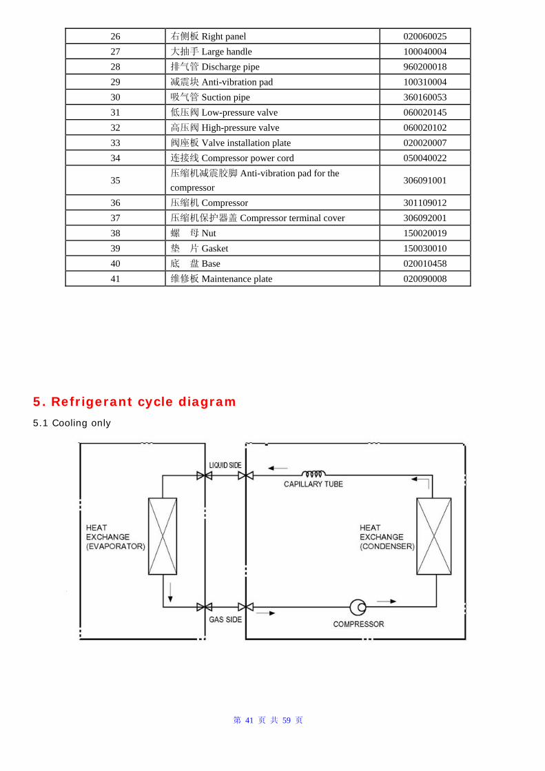
第 41 页 共 59 页
26 右侧板 Right panel 020060025 27 大抽手 Large handle 100040004 28 排气管 Discharge pipe 960200018 29 减震块 Anti-vibration pad 100310004 30 吸气管 Suction pipe 360160053 31 低压阀 Low-pressure valve 060020145 32 高压阀 High-pressure valve 060020102 33 阀座板 Valve installation plate 020020007 34 连接线 Compressor power cord 050040022
35 压缩机减震胶脚 Anti-vibration pad for the compressor
306091001
36 压缩机 Compressor 301109012 37 压缩机保护器盖 Compressor terminal cover 306092001 38 螺 母 Nut 150020019 39 垫 片 Gasket 150030010 40 底 盘 Base 020010458 41 维修板 Maintenance plate 020090008
5. Refrigerant cycle diagram
5.1 Cooling only
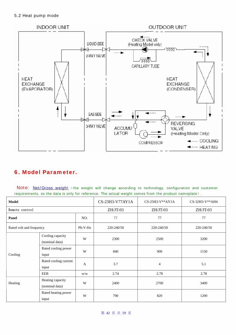
第 42 页 共 59 页
5.2 Heat pump mode
6. Model Parameter.
Note: Net/Gross weight( the weight will change according to technology, configuration and customer
requirements. so the data is only for reference. The actual weight comes from the product nameplate).
Model CS-23H3-V77AY1A CS-25H3-V**AY1A CS-32H3-V**AH4
Remote control ZH/JT-03 ZH/JT-03 ZH/JT-03
Panel NO. 77 77 77
Rated volt and frequency Ph-V-Hz 220-240/50 220-240/50 220-240/50
Cooling capacity
(nominal data) W 2300 2500 3200
Rated cooling power
input W 840 900 1150
Rated cooling current
input A 3.7 4 5.1
Cooling
EER w/w 2.74 2.78 2.78
Heating capacity
(nominal data) W 2400 2700 3400 Heating
Rated heating power
input W 790 820 1200
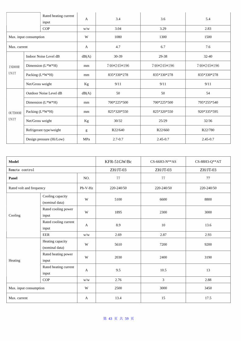
第 43 页 共 59 页
Rated heating current
input A 3.4 3.6 5.4
COP w/w 3.04 3.29 2.83
Max. input consumption W 1080 1300 1500
Max. current A 4.7 6.7 7.6
Indoor Noise Level dB dB(A) 30-39 29-38 32-40
Dimension (L*W*H) mm 746*245*196 746*245*196 746*245*196
Packing (L*W*H) mm 835*330*278 835*330*278 835*330*278
INDOOR
UNIT
Net/Gross weight Kg 9/11 9/11 9/11
Outdoor Noise Level dB dB(A) 50 50 54
Dimension (L*W*H) mm 700*225*500 700*225*500 795*255*540
Packing (L*W*H) mm 825*320*550 825*320*550 920*335*595
Net/Gross weight Kg 30/32 25/29 32/36
Refrigerant type/weight g R22/640 R22/660 R22/780
OUTDOOR
UNIT
Design pressure (Hi/Low) MPa 2.7-0.7 2.45-0.7 2.45-0.7
Model KFR-51GW/Bc CS-66H3-N**AS CS-88H3-Q**AT
Remote control ZH/JT-03 ZH/JT-03 ZH/JT-03
Panel NO. 77 77 77
Rated volt and frequency Ph-V-Hz 220-240/50 220-240/50 220-240/50
Cooling capacity
(nominal data) W 5100 6600 8800
Rated cooling power
input W 1895 2300 3000
Rated cooling current
input A 8.9 10 13.6
Cooling
EER w/w 2.69 2.87 2.93
Heating capacity
(nominal data) W 5610 7200 9200
Rated heating power
input W 2030 2400 3190
Rated heating current
input A 9.5 10.5 13
Heating
COP w/w 2.76 3 2.88
Max. input consumption W 2500 3000 3450
Max. current A 13.4 15 17.5
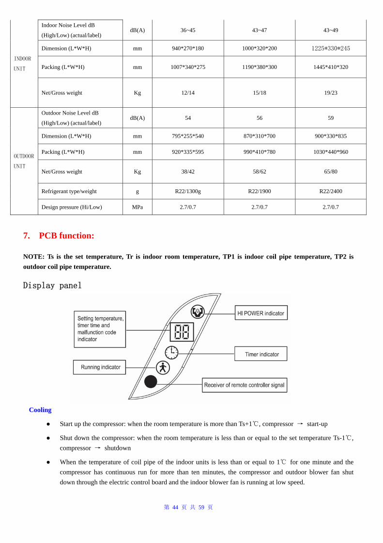
第 44 页 共 59 页
Indoor Noise Level dB
(High/Low) (actual/label) dB(A) 36~45 43~47 43~49
Dimension (L*W*H) mm 940*270*180 1000*320*200 1225*330*245
Packing (L*W*H) mm 1007*340*275 1190*380*300 1445*410*320 INDOOR
UNIT
Net/Gross weight Kg 12/14 15/18 19/23
Outdoor Noise Level dB
(High/Low) (actual/label) dB(A) 54 56 59
Dimension (L*W*H) mm 795*255*540 870*310*700 900*330*835
Packing (L*W*H) mm 920*335*595 990*410*780 1030*440*960
Net/Gross weight Kg 38/42 58/62 65/80
Refrigerant type/weight g R22/1300g R22/1900 R22/2400
OUTDOOR
UNIT
Design pressure (Hi/Low) MPa 2.7/0.7 2.7/0.7 2.7/0.7
7. PCB function:
NOTE: Ts is the set temperature, Tr is indoor room temperature, TP1 is indoor coil pipe temperature, TP2 is outdoor coil pipe temperature.
Display panel
Cooling
● Start up the compressor: when the room temperature is more than Ts+1℃, compressor → start-up
● Shut down the compressor: when the room temperature is less than or equal to the set temperature Ts-1℃, compressor → shutdown
● When the temperature of coil pipe of the indoor units is less than or equal to 1℃ for one minute and the compressor has continuous run for more than ten minutes, the compressor and outdoor blower fan shut down through the electric control board and the indoor blower fan is running at low speed.
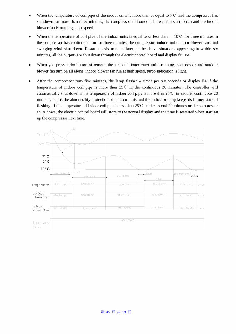
第 45 页 共 59 页
● When the temperature of coil pipe of the indoor units is more than or equal to 7℃ and the compressor has shutdown for more than three minutes, the compressor and outdoor blower fan start to run and the indoor blower fan is running at set speed.
● When the temperature of coil pipe of the indoor units is equal to or less than -10℃ for three minutes in the compressor has continuous run for three minutes, the compressor, indoor and outdoor blower fans and swinging wind shut down. Restart up six minutes later; if the above situations appear again within six minutes, all the outputs are shut down through the electric control board and display failure.
● When you press turbo button of remote, the air conditioner enter turbo running, compressor and outdoor blower fan turn on all along, indoor blower fan run at high speed, turbo indication is light.
● After the compressor runs five minutes, the lamp flashes 4 times per six seconds or display E4 if the temperature of indoor coil pips is more than 25℃ in the continuous 20 minutes. The controller will automatically shut down if the temperature of indoor coil pips is more than 25℃ in another continuous 20 minutes, that is the abnormality protection of outdoor units and the indicator lamp keeps its former state of flashing. If the temperature of indoor coil pips is less than 25℃ in the second 20 minutes or the compressor shuts down, the electric control board will store to the normal display and the time is restarted when starting up the compressor next time.
1° C7° C
Tr
-10° C
compressor
outdoor blower fan
door blower fan
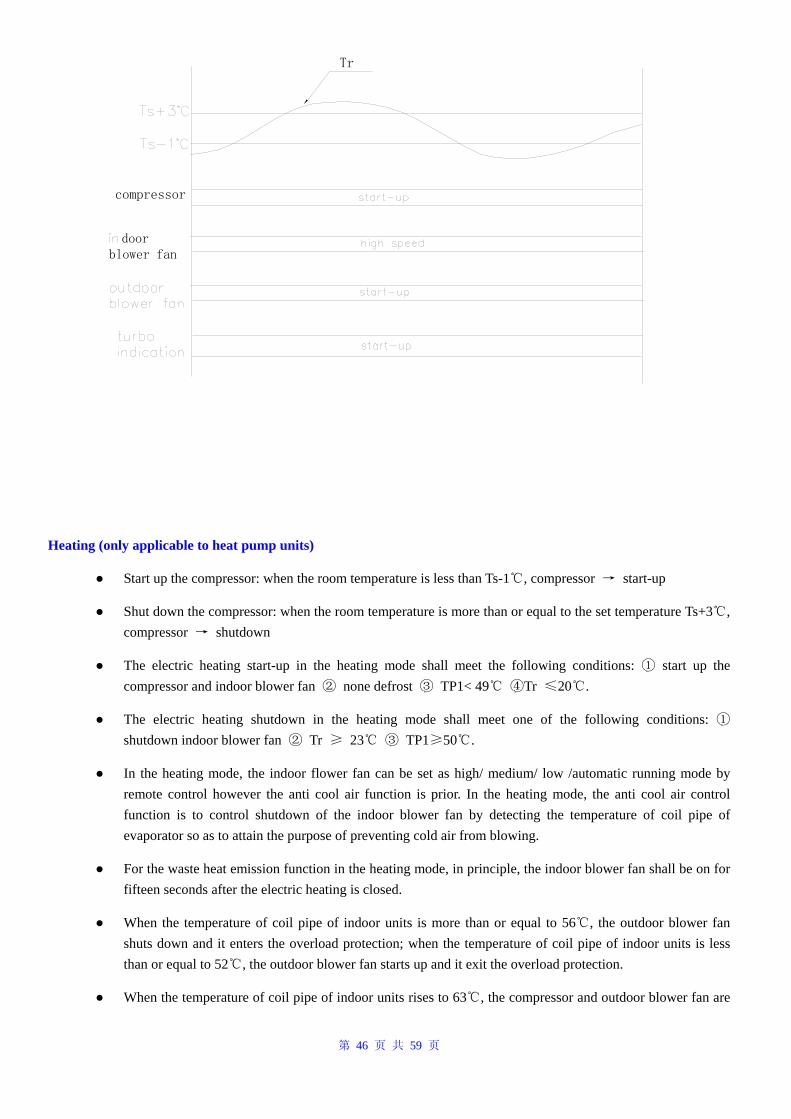
第 46 页 共 59 页
compressor
door blower fan
Tr
Heating (only applicable to heat pump units)
● Start up the compressor: when the room temperature is less than Ts-1℃, compressor → start-up
● Shut down the compressor: when the room temperature is more than or equal to the set temperature Ts+3℃, compressor → shutdown
● The electric heating start-up in the heating mode shall meet the following conditions: ① start up the compressor and indoor blower fan ② none defrost ③ TP1< 49℃ ④Tr ≤20℃.
● The electric heating shutdown in the heating mode shall meet one of the following conditions: ① shutdown indoor blower fan ② Tr ≥ 23℃ ③ TP1≥50℃.
● In the heating mode, the indoor flower fan can be set as high/ medium/ low /automatic running mode by remote control however the anti cool air function is prior. In the heating mode, the anti cool air control function is to control shutdown of the indoor blower fan by detecting the temperature of coil pipe of evaporator so as to attain the purpose of preventing cold air from blowing.
● For the waste heat emission function in the heating mode, in principle, the indoor blower fan shall be on for fifteen seconds after the electric heating is closed.
● When the temperature of coil pipe of indoor units is more than or equal to 56℃, the outdoor blower fan shuts down and it enters the overload protection; when the temperature of coil pipe of indoor units is less than or equal to 52℃, the outdoor blower fan starts up and it exit the overload protection.
● When the temperature of coil pipe of indoor units rises to 63℃, the compressor and outdoor blower fan are
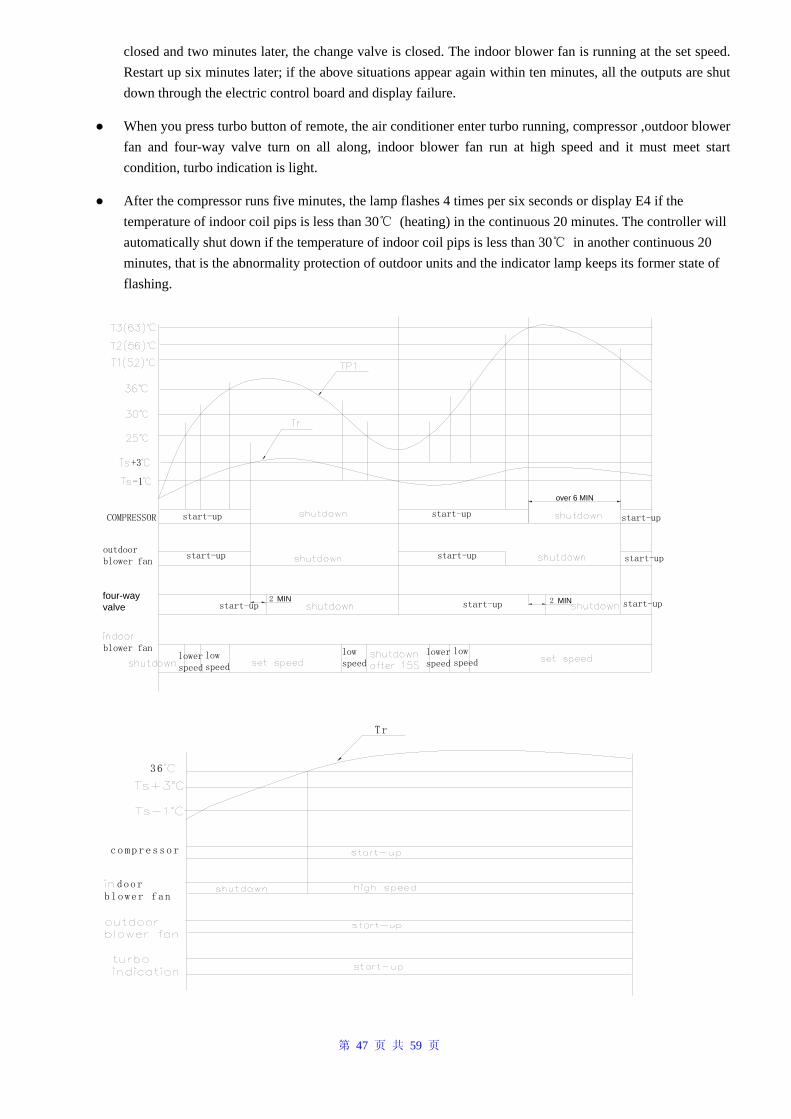
第 47 页 共 59 页
closed and two minutes later, the change valve is closed. The indoor blower fan is running at the set speed. Restart up six minutes later; if the above situations appear again within ten minutes, all the outputs are shut down through the electric control board and display failure.
● When you press turbo button of remote, the air conditioner enter turbo running, compressor ,outdoor blower fan and four-way valve turn on all along, indoor blower fan run at high speed and it must meet start condition, turbo indication is light.
● After the compressor runs five minutes, the lamp flashes 4 times per six seconds or display E4 if the temperature of indoor coil pips is less than 30℃ (heating) in the continuous 20 minutes. The controller will automatically shut down if the temperature of indoor coil pips is less than 30℃ in another continuous 20 minutes, that is the abnormality protection of outdoor units and the indicator lamp keeps its former state of flashing.
+3
-1
COMPRESSOR start-up start-up
outdoor blower fan
start-up start-up start-up
start-up
blower fan
lower speed
low speed
low speed
lower speed
low speed
start-up2 MIN 2 MINstart-up start-up
over 6 MIN
four-way valve
compressor
door blower fan
Tr
36
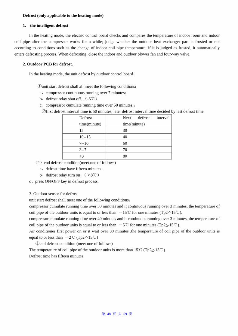
第 48 页 共 59 页
Defrost (only applicable to the heating mode)
1. the intelligent defrost
In the heating mode, the electric control board checks and compares the temperature of indoor room and indoor coil pipe after the compressor works for a while; judge whether the outdoor heat exchanger part is frosted or not according to conditions such as the change of indoor coil pipe temperature; if it is judged as frosted, it automatically enters defrosting process. When defrosting, close the indoor and outdoor blower fan and four-way valve.
2. Outdoor PCB for defrost.
In the heating mode, the unit defrost by outdoor control board: unit start defrost shall① all meet the following conditions: a、compressor continuous running over 7 minutes; b、defrost relay shut off;(-5℃) c、compressor cumulate running time over 50 minutes.; first defrost interval time is 50 minutes, later defrost interval time decided by last defrost time.②
Defrost time(minute)
Next defrost interval time(minute)
15 30 10--15 40 7--10 60 3--7 70 ≤3 80
(2)end defrost condition(meet one of follows) a、defrost time have fifteen minutes. b、defrost relay turn on;(>8℃) c、press ON/OFF key in defrost process. 3. Outdoor sensor for defrost unit start defrost shall meet one of the following conditions: compressor cumulate running time over 30 minutes and it continuous running over 3 minutes, the temperature of coil pipe of the outdoor units is equal to or less than -15 for one minutes (Tp2≤℃ -15 ).℃ compressor cumulate running time over 40 minutes and it continuous running over 3 minutes, the temperature of coil pipe of the outdoor units is equal to or less than -5 for one minutes (Tp2≤℃ -15 ).℃ Air conditioner first power on or it wait over 30 minutes ,the temperature of coil pipe of the outdoor units is equal to or less than -2 (Tp2≤℃ -15 )℃ end defrost condition② (meet one of follows) The temperature of coil pipe of the outdoor units is more than 15 (Tp2≥℃ -15 ).℃ Defrost time has fifteen minutes.
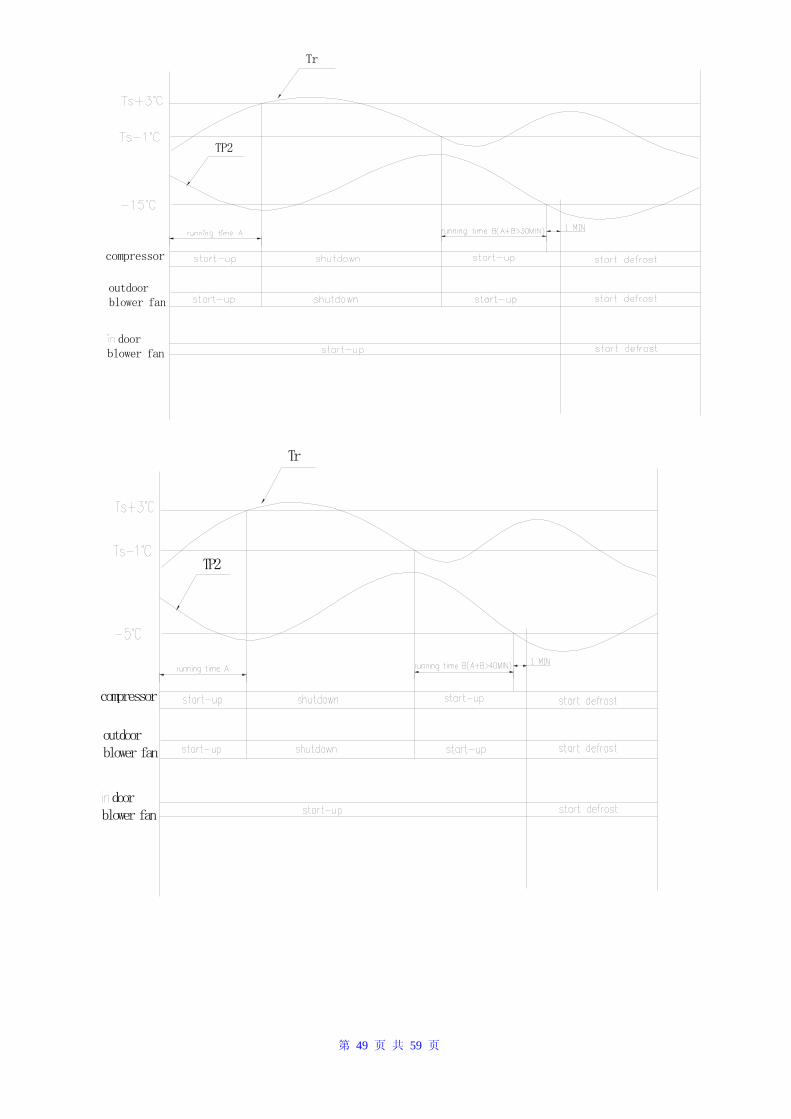
第 49 页 共 59 页
compressor
outdoor blower fan
door blower fan
TP2
Tr
compressor
outdoor blower fan
door blower fan
TP2
Tr
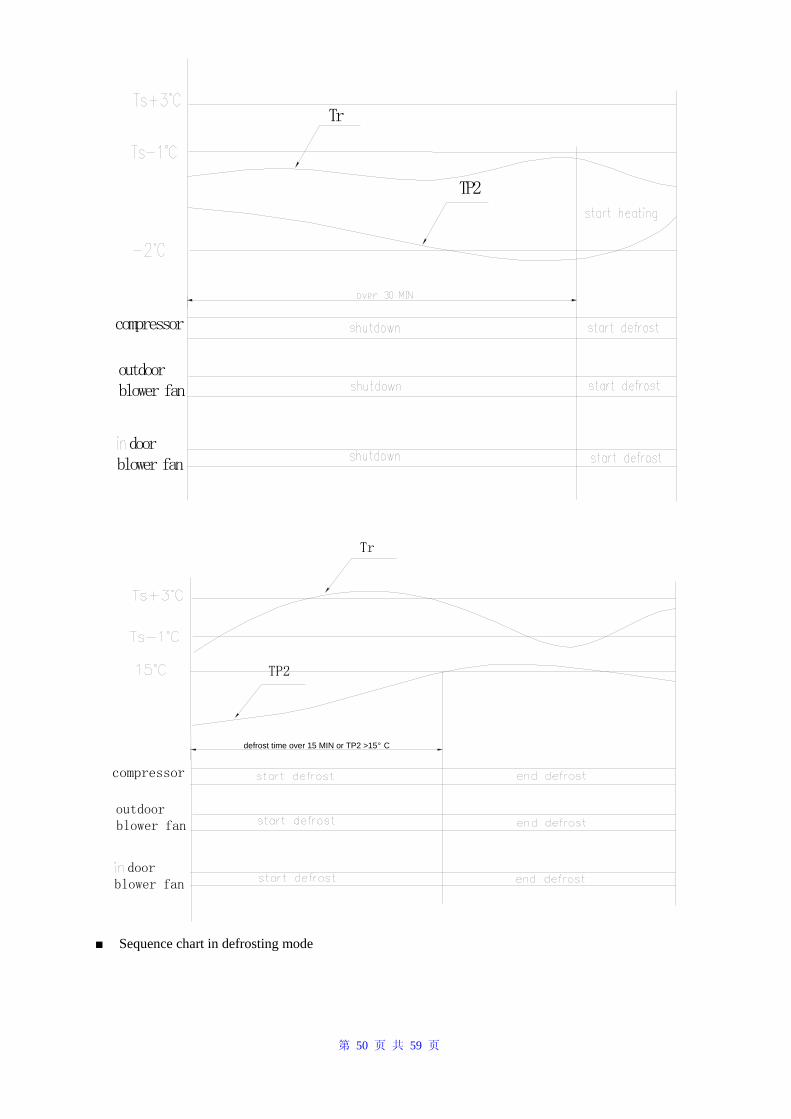
第 50 页 共 59 页
Tr
compressor
outdoor blower fan
door blower fan
TP2
outdoor blower fan
door blower fan
TP2
defrost time over 15 MIN or TP2 >15° C
Tr
compressor
■ Sequence chart in defrosting mode
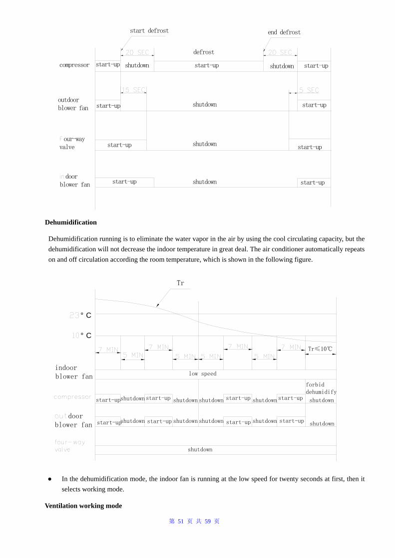
第 51 页 共 59 页
end defrost
start-up shutdown start-up shutdown start-up
start-upstart-up shutdown
defrost
our-way valve
door blower fan
start-upstart-up
start-up start-up
shutdown
shutdown
outdoor blower fan
compressor
start defrost
Dehumidification
Dehumidification running is to eliminate the water vapor in the air by using the cool circulating capacity, but the dehumidification will not decrease the indoor temperature in great deal. The air conditioner automatically repeats on and off circulation according the room temperature, which is shown in the following figure.
indoor blower fan
° C
° C
door blower fan
Tr
shutdown shutdown shutdown shutdown shutdown
shutdownshutdownshutdownshutdownshutdown
low speed
Tr≤10℃
shutdown
start-up
start-up start-up
start-up start-up
start-up start-up
start-up
forbid dehumidify
● In the dehumidification mode, the indoor fan is running at the low speed for twenty seconds at first, then it selects working mode.
Ventilation working mode
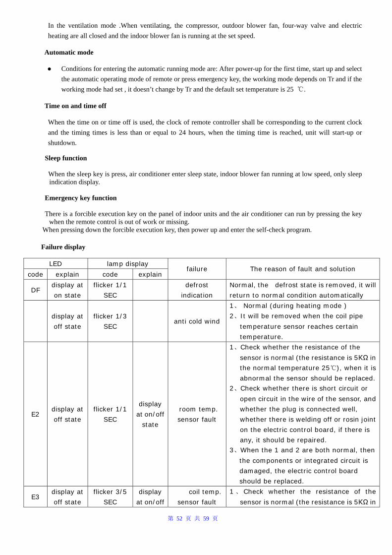
第 52 页 共 59 页
In the ventilation mode .When ventilating, the compressor, outdoor blower fan, four-way valve and electric heating are all closed and the indoor blower fan is running at the set speed.
Automatic mode
● Conditions for entering the automatic running mode are: After power-up for the first time, start up and select the automatic operating mode of remote or press emergency key, the working mode depends on Tr and if the working mode had set , it doesn’t change by Tr and the default set temperature is 25 ℃.
Time on and time off
When the time on or time off is used, the clock of remote controller shall be corresponding to the current clock and the timing times is less than or equal to 24 hours, when the timing time is reached, unit will start-up or shutdown.
Sleep function
When the sleep key is press, air conditioner enter sleep state, indoor blower fan running at low speed, only sleep indication display.
Emergency key function There is a forcible execution key on the panel of indoor units and the air conditioner can run by pressing the key
when the remote control is out of work or missing. When pressing down the forcible execution key, then power up and enter the self-check program.
Failure display
LED lamp display
code explain code explain failure The reason of fault and solution
DF display at
on state
flicker 1/1
SEC
defrost
indication
Normal, the defrost state is removed, it will
return to normal condition automatically
display at
off state
flicker 1/3
SEC anti cold wind
1、 Normal (during heating mode )
2、It will be removed when the coil pipe
temperature sensor reaches certain
temperature.
E2 display at
off state
flicker 1/1
SEC
display
at on/off
state
room temp.
sensor fault
1、Check whether the resistance of the
sensor is normal (the resistance is 5КΩ in
the normal temperature 25℃), when it is
abnormal the sensor should be replaced.
2、Check whether there is short circuit or
open circuit in the wire of the sensor, and
whether the plug is connected well,
whether there is welding off or rosin joint
on the electric control board, if there is
any, it should be repaired.
3、When the 1 and 2 are both normal, then
the components or integrated circuit is
damaged, the electric control board
should be replaced.
E3 display at
off state
flicker 3/5
SEC
display
at on/off
coil temp.
sensor fault
1 、 Check whether the resistance of the
sensor is normal (the resistance is 5КΩ in
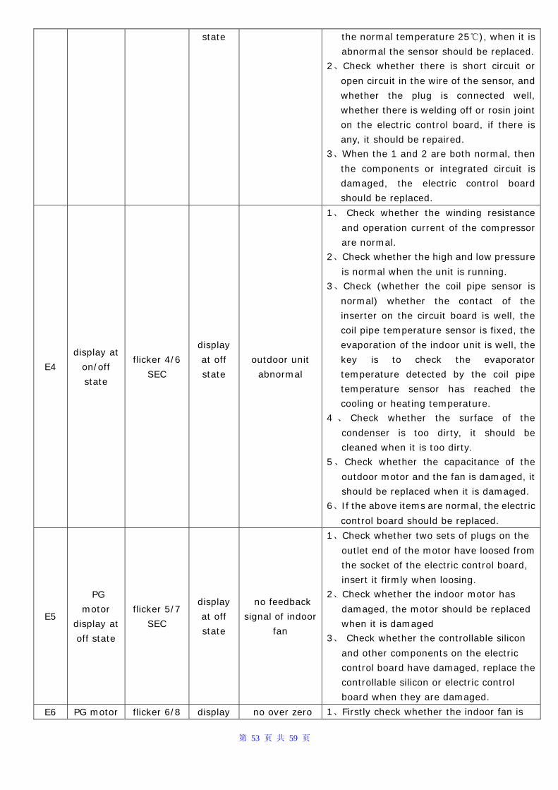
第 53 页 共 59 页
state the normal temperature 25℃), when it is
abnormal the sensor should be replaced.
2、Check whether there is short circuit or
open circuit in the wire of the sensor, and
whether the plug is connected well,
whether there is welding off or rosin joint
on the electric control board, if there is
any, it should be repaired.
3、When the 1 and 2 are both normal, then
the components or integrated circuit is
damaged, the electric control board
should be replaced.
E4
display at
on/off
state
flicker 4/6
SEC
display
at off
state
outdoor unit
abnormal
1、 Check whether the winding resistance
and operation current of the compressor
are normal.
2、Check whether the high and low pressure
is normal when the unit is running.
3、Check (whether the coil pipe sensor is
normal) whether the contact of the
inserter on the circuit board is well, the
coil pipe temperature sensor is fixed, the
evaporation of the indoor unit is well, the
key is to check the evaporator
temperature detected by the coil pipe
temperature sensor has reached the
cooling or heating temperature.
4 、 Check whether the surface of the
condenser is too dirty, it should be
cleaned when it is too dirty.
5、Check whether the capacitance of the
outdoor motor and the fan is damaged, it
should be replaced when it is damaged.
6、If the above items are normal, the electric
control board should be replaced.
E5
PG
motor
display at
off state
flicker 5/7
SEC
display
at off
state
no feedback
signal of indoor
fan
1、Check whether two sets of plugs on the
outlet end of the motor have loosed from
the socket of the electric control board,
insert it firmly when loosing.
2、Check whether the indoor motor has
damaged, the motor should be replaced
when it is damaged
3、 Check whether the controllable silicon
and other components on the electric
control board have damaged, replace the
controllable silicon or electric control
board when they are damaged.
E6 PG motor flicker 6/8 display no over zero 1、Firstly check whether the indoor fan is
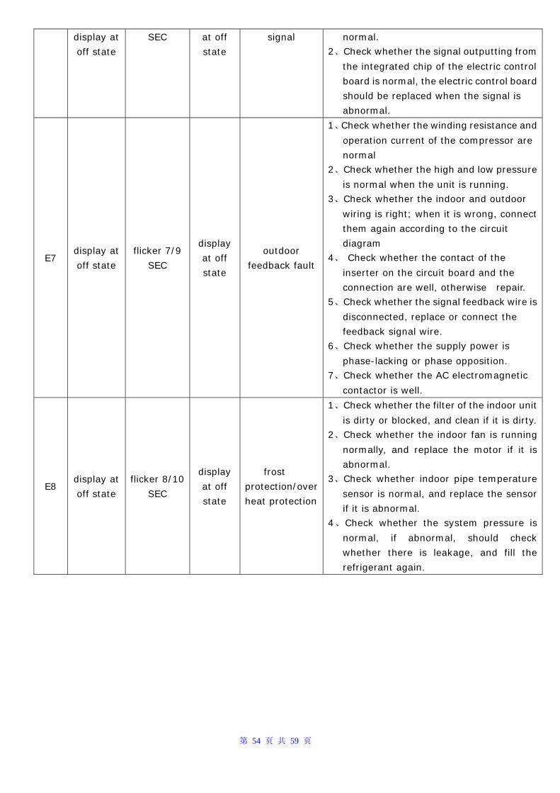
第 54 页 共 59 页
display at
off state
SEC at off
state
signal normal.
2、Check whether the signal outputting from
the integrated chip of the electric control
board is normal, the electric control board
should be replaced when the signal is
abnormal.
E7 display at
off state
flicker 7/9
SEC
display
at off
state
outdoor
feedback fault
1、Check whether the winding resistance and
operation current of the compressor are
normal
2、Check whether the high and low pressure
is normal when the unit is running.
3、Check whether the indoor and outdoor
wiring is right; when it is wrong, connect
them again according to the circuit
diagram
4、 Check whether the contact of the
inserter on the circuit board and the
connection are well, otherwise repair.
5、Check whether the signal feedback wire is
disconnected, replace or connect the
feedback signal wire.
6、Check whether the supply power is
phase-lacking or phase opposition.
7、Check whether the AC electromagnetic
contactor is well.
E8 display at
off state
flicker 8/10
SEC
display
at off
state
frost
protection/over
heat protection
1、Check whether the filter of the indoor unit
is dirty or blocked, and clean if it is dirty.
2、Check whether the indoor fan is running
normally, and replace the motor if it is
abnormal.
3、Check whether indoor pipe temperature
sensor is normal, and replace the sensor
if it is abnormal.
4、Check whether the system pressure is
normal, if abnormal, should check
whether there is leakage, and fill the
refrigerant again.
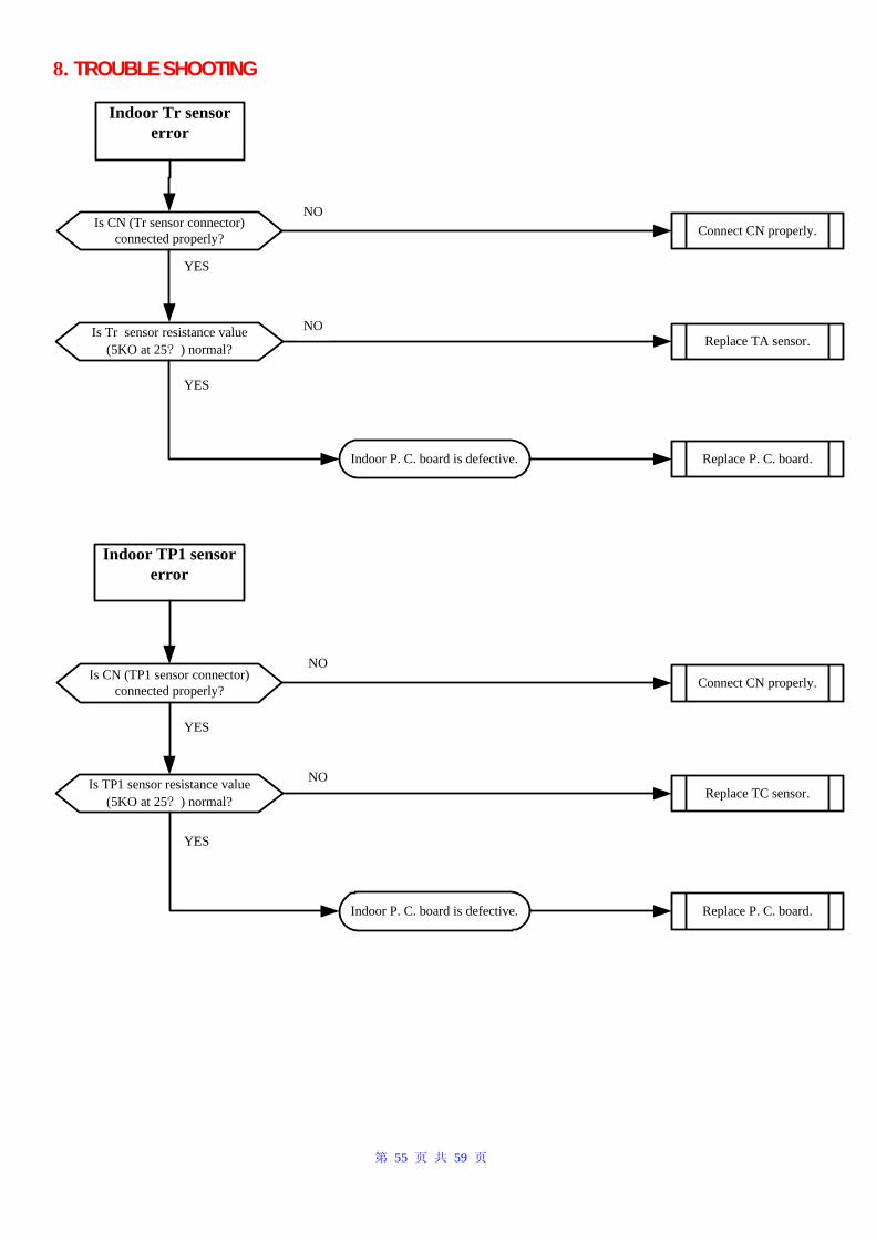
第 55 页 共 59 页
8. TROUBLE SHOOTING
Is CN (Tr sensor connector)connected properly?
Is Tr sensor resistance value(5KO at 25? ) normal?
Indoor P. C. board is defective. Replace P. C. board.
Connect CN properly.
Replace TA sensor.
Is CN (TP1 sensor connector)connected properly?
Is TP1 sensor resistance value(5KO at 25? ) normal?
Indoor P. C. board is defective. Replace P. C. board.
Connect CN properly.
Replace TC sensor.
YES
YES
YES
YES
NO
NO
NO
NO
Indoor Tr sensor error
Indoor TP1 sensor error
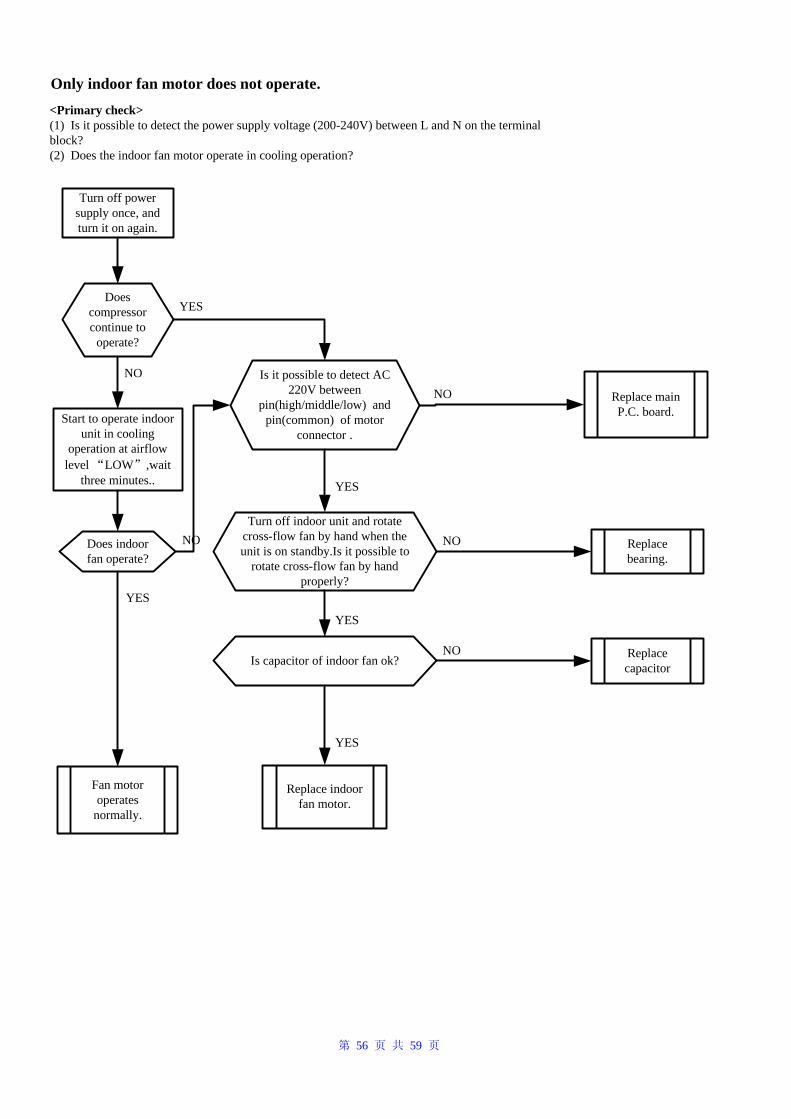
第 56 页 共 59 页
Turn off power supply once, and turn it on again.
Does compressor continue to
operate?
Start to operate indoor unit in cooling
operation at airflow level “LOW”,wait
three minutes..
Does indoor fan operate?
Fan motor operates
normally.
Is it possible to detect AC 220V between
pin(high/middle/low) and pin(common) of motor
connector .
Replace indoor fan motor.
Replace main P.C. board.
Replace bearing.
YES
YES
YES
NO
NO
NO
Turn off indoor unit and rotate cross-flow fan by hand when the unit is on standby.Is it possible to
rotate cross-flow fan by hand properly?
Only indoor fan motor does not operate.
Is capacitor of indoor fan ok?
YES
NO
YES
Replace capacitor
NO
<Primary check>(1) Is it possible to detect the power supply voltage (200-240V) between L and N on the terminal block?(2) Does the indoor fan motor operate in cooling operation?
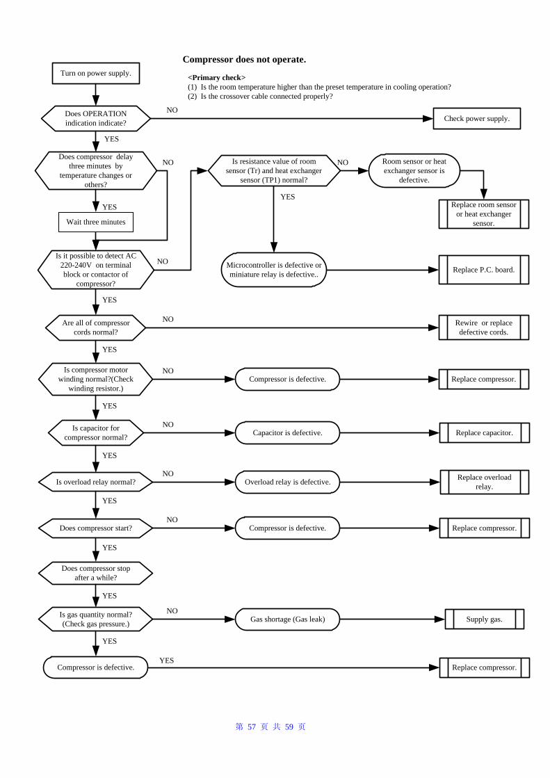
第 57 页 共 59 页
Compressor does not operate.Turn on power supply.
Does compressor delay three minutes by
temperature changes or others?
Does OPERATION indication indicate?
Is it possible to detect AC 220-240V on terminal block or contactor of
compressor?
Are all of compressor cords normal?
Is compressor motor winding normal?(Check
winding resistor.)
Is capacitor for compressor normal?
Is overload relay normal?
Does compressor start?
Does compressor stop after a while?
Is gas quantity normal? (Check gas pressure.)
Microcontroller is defective or miniature relay is defective..
Is resistance value of room sensor (Tr) and heat exchanger
sensor (TP1) normal?
Room sensor or heat exchanger sensor is
defective.
Replace room sensor or heat exchanger
sensor.
Compressor is defective.
Capacitor is defective.
Overload relay is defective.
Compressor is defective.
Gas shortage (Gas leak)
Compressor is defective.
Replace P.C. board.
Rewire or replace defective cords.
Replace compressor.
Replace capacitor.
Replace overload relay.
Supply gas.
Replace compressor.
YES
YES
YES
YES
YES
YES
YES
YES
YES
YES
YES
YES
NO
NO NO
NO
NO
NO
NO
NO
NO
NO
Check power supply.
Replace compressor.
Wait three minutes
<Primary check>(1) Is the room temperature higher than the preset temperature in cooling operation?(2) Is the crossover cable connected properly?
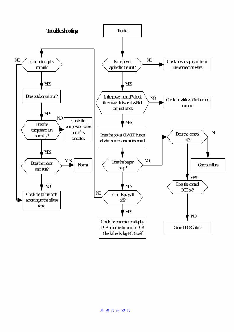
第 58 页 共 59 页
Trouble
Is the power applied to the unit?
Check power supply mains or interconnection wires
Is the power normal? check the voltage between L&N of
terminal block
Check the wiring of indoor and outdoor
Press the power ON/OFF button of wire control or remote control
YES
YES
NO
NO
Does the beeper beep?
Is the display all off?
Check the connector on display PCB connected to control PCB Check the display PCB itself
Is the unit display normal?
Does outdoor unit run?
Does the compressor run
normally?
Check the failure code according to the failure
table
Normal
Check the compressor ,wires
and it’s capacitor.
YES
YES
YES
YES
YES
YES
NO
NO
NO
Does the control ok?
Does the control PCB ok?
Control failure
Control PCB failure
NO
NO
YES
NO
Trouble shooting
NO
Does the indoor unit run?
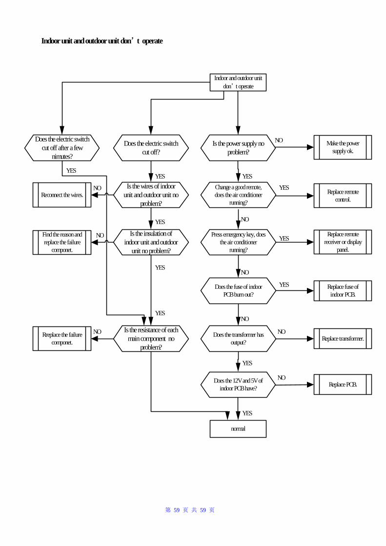
第 59 页 共 59 页
Indoor unit and outdoor unit don’t operate
Indoor and outdoor unit don’t operate
Press emergency key, does the air conditioner
running?
Replace fuse of indoor PCB.
YES
YES
YES
NO
NO
NO
NO
Make the power supply ok.
Replace remote control.
YES
NO
Replace remote receiver or display
panel.
NO
YES
YES
Replace transformer.Does the transformer has output?
Does the fuse of indoor PCB burn out?
Change a good remote, does the air conditioner
running?
Is the power supply no problem?
Does the 12V and 5V of indoor PCB have? Replace PCB.
normal
Does the electric switch cut off?
Does the electric switch cut off after a few
nimutes?
Is the wires of indoor unit and outdoor unit no
problem?
YES
Reconnect the wires.NO
Is the insulation of indoor unit and outdoor
unit no problem?
YES
Find the reason and replace the failure
componet.
NO
Is the resistance of each main component no
problem?
Rreplace the failure componet.
NO
YES
YES
YES