t::1 ,3 . CIVIL ENGINEERING STUDIES
60
t::1 ,3 . CIVIL ENGINEERING STUDIES STRUCTURAL RESEARCH SERIES NO. 159 STATIC AND DYNA IC TESTS f STEEL FRA E STRUCTURES tNT THE INELASTIC RANGE F DEF RMATI N by J. M. Massard final Report to RESEARCH DIRECTORATE AIR fORCE SPECIAL WEAPONS CENTER Air Research and Development Command Contract AF 3 3 (61 6) - 17 0 Project 1 080 Task 10803 UNIVERSITY OF ILLINOIS URBANA; ILLINOIS MAY 1957
Transcript of t::1 ,3 . CIVIL ENGINEERING STUDIES
t::1 ,3
. CIVIL ENGINEERING STUDIES STRUCTURAL RESEARCH SERIES NO. 159
STATIC AND DYNA IC TESTS
f STEEL FRA E STRUCTURES tNT THE
INELASTIC RANGE F DEF RMATI N
by
J. M. Massard
final Report to
RESEARCH DIRECTORATE
AIR fORCE SPECIAL WEAPONS CENTER
Air Research and Development Command
Contract AF 3 3 (61 6) - 17 0
Project 1 080
Task 10803
UNIVERSITY OF ILLINOIS
URBANA; ILLINOIS
MAY 1957
AFSWC ~1'R"" 57 =23
FINAL REPOR.T
STATIC ~D DYN~IC TESTS OF STEEL FRAME STRUCTURES
Project ~
Task Contract~
INTO TH:E.i INELASTIC RANGE OF DEFORMATION
by
Jo Mo Massard
Approved by
No Mo Ne-wmark
University of Illinois
Department of Civil Engineering
May 1957
RESEARCH DIRECTORATE AIR FORCE SPECIAL WEAPONS CENTER.
Air Research and Development Command Ki.rtla.nd Air Force Base, New Mexico
1080 10803
Approved~
AF 33( 616) -170 Eric lio Wang Chief} Structures Division

STATIC .AND DYNAMIC TESTS OF STEEL FRAME STRUCTURES INTO THE
INELASTIC RANGE OF DEFORMATION
CONTENTS
10 INTRODUCTION
10 Purpose and Scope
20 Acknowledgment S 0
110 CONCLUSIONS
10 Comment
20 Conclusions 0 0
1110 GENERAL COMMENTS
General Commentso 0
IV 0 SUMMARY OF THE IN\lESTIGATION
Summary of the Investigation 0
Vo REVIEW OF THE INVESTIGATION
Survey of Literature 0
20 General Nature of the Investigation o 0'
30 .Analytical Studieso 0
40 Devel.opment of Testing Apparatus"
50 Experimental Investigations
BIBLIOGRAPHY " 0 0 " " 0 0 0 0 6 0 0
APPENDIX A~ ABSTRACTS OF REPORTS PREPARED UNDER CONTRACT
1
1
3
6
7
9
9
10
11
12
15
AF 33( 616) =1700 0 0 6 0 0 0 0 0 0 0 ; 0 0 0 0 17
APPENDIX B ~ TABULATION OF TESTS PERFORMED UNDER CONTRACT AF 33(616)=1700 0 0 0 0 0 0 0 0 0 0 0 0 0 0 0 46
TABLE OF NOTATION FOR APPENDIX Boo 47

STATIC AND Dl'NAMIC TESTS OF STEEL FRAME STRUCTURES INTO THE
INELASTIC RANGE OF DEFORMATION
10 INTRODUCTION
10 Purpose and Scope
The purpose of the program which has been conducted at the
University of Illinois under Contract AF 33(616) ... 170, Task 10803, Project
1080, can be stated in general terms as Uthe performance of tests and
analyses to obtain basic information concerning the behavior of steel
structural frames and elements when subjected to known static and dyn~ic
loadings that produce extensive inelastic deformationso Jtr
The project was begun in July of 1952 and., in its various phases J
has been carried on continuously since then 0 During this time three Final
Reports 3, 9 have been writteno However, since this is to be the last
F"inal, Report on the contract J the entire project will be summarized" The
review of such an extensive program. must necessarily be cursory; however,
it is hoped that this presentation will provide the reader with enough
information to permit his understanding the investigation as regards its
purpose J scope J results produced and their appli.cabili ty to problems per.,.,
taining to the inelastic behavior of steel frame structureso
2" Acknowledgments
lhe investigation described in this report was performed by staff
members of the University of Illinois in cooperation 1.;ri th the Wright Air
* The numbers refer to entries in the Bibliography presented at the end of the text 0

Development Center and the Air Force Special Weapons Center, Department of
the Air Force, under Contract AF 33(616)~170 as Task 10803, Project 10800
The project was conducted in the structural Research Laboratory
of the Department of Civil Engineering under the general direction of
No Mo Newmark, Professor of Civil Engineering and Head of the Department.
Project supervisors have been, in chronological order; Go Ko Sinnamon,
Research Assistant Professor of Civil Enginee~~ng; Fe Lo Howland, Research
Associate in Civil Engineering, and Jo Mo Massard, Research Assistant
Professor of Civil Engineeringo
The many re.search assistants and research associates who have
been associated directly with the project include Ro Jo Munz, Ro 30
Mayerj~, Wo Egger} Ro Fa Wojcieszak, Jo Ho Sams, Co Lo Wilkinson, Lo Wo
Heilmann, Ae Aug, and D. McDonald 0
One Technical Report produced with project funds was based upon a
doctoral dissertatioD. by Wo 30 Rallo
The instrumentation used throughout the investigation was, in
general, the responsibillty of V 0 J 0 McDonald, Research Assistant Professor
of Civil Engineeringo In additi.on to those individuals named many other
members of the staff of the university of Illinois have aided the advance-
ment of the program 0 Not the least of these were the personnel of the
Civil Engineering Shop, and the many student helpers employed to perform
the routine computational work necessaryo

IIG CONCLUSIONS
10 Comment
The conclusions described below were reached as the result of
tests performed under the following conditionso The material in all cases
was mild structural steel which nominally met the requirements of ASTM
Specification A7 = 56To All of the tests were performed at room tempera-
ture and at rates which were either nslowli (maximum load and deflection
reached in several minutes, or a few hours in some cases) or YVrapidit
(maximums reached i.n times on the order of fifteen to fifty milliseconds ) 0
The configurations of the test systems were such that specimen resistances
were not limited by buckling of any type until the maximum strains were
well into the range of strain hardeningo All failures were ductile; i .. eo,
no brittle fractures 0
20 Conclusions
lo The actual resistance of a mild steel structural element to
an imposed inelastic deformation increases with the rate of that deforma
and is also dependent upon the time involved!Y 8, 9, 11
20 In most of the specimen types in which it occurred,. local
inelastic buckling was less pronounced in the rapid tests than in the slow
ones:1 which indicates that the effecti veness of the 'beam section was
t t 5, 8, 11 increased wih the rapidi y of deformationo
3
)0 An axial load on a structural member decreases the ability of
the member to resist lateral load, but does not affect appreciably the
total resistance of the member to an external moment except in the limited
range of deformation immediately following ini tialf-l:yieldingo 3, 6, 8, 11
4
40 The effect of shear upon the moment capacity of an 8 WF 58
section loaded laterally and slowly in the plane of the major axis was
found to be negligible even for a beam having an equivalent cantilever span
to depth ratio as low as two 0 However» in a region of constant shear but
gra~ient moment, the development of a general shear yielding condition in
the we-b caused. deflections considerably greater than those which resulted
I 2 from concentrated yielding primarily caused by momento
50 In most of the structural elements and models tested, the
ini.ti.al Uelastic H region of the resistance""deflection relationship had a
slope less than that derived using elementary theory and assumed ideal
condi.tions of support 0
60 .A static resistance"",deflection function for a simpl;e struc'"
t1rral element or a relatively simple structure can be determined with good
accuracy by usi.ng practicable approximations to relate strains to deflec-
tions, and then computi.ng resistance on the basis of the known static
stress-strain characteristics of the material involvedo 1 , 3, 4
70 For research purposes requi.ring good accuracy, an equivalent
resistance-deflection function for a relatively simply structure subjected
to rapid deformation can be determined in a manner similar to that mentioned
above USing, of course, the dynamic properties of the material in the deter:...
mtnation of the resistance 0 The procedure should be such that the equiva ....
lent resistance is computed using instantaneous material stresses at the
critical sections which are c.ompatible with the strains, straining rates,
and times involvedo The total resistance so determined (which does not in-'
clude inertia forces) is actually a function of ttme and velocity as well as
displacement (as was indicated tn paragraph 110201)7 andy therefore, is

5
strictly valid only for the particular case considered, or for others very
. . 1 dId' ft· d ttl f' t . 11 Slml ar as regar s oalng unc lon an s.ruc ura con 19ura lono
80 However, since the effect of delayed yielding is probably
important only in cases of short duration impulse, and the general yielding
reSl,stance of mild steel is relatively insensitive to changes of straining
rates wi thin one or two orders of magnitude , suitable accuracy can be
obtained in most practical problems (where the dynamic loading function is
seldom kno'WIl with great accuracy) simply by increasing the static inelastic
resistance of the structure (as determi,ned by use of the procedure outlined
in paragraph 1102 .. 6) in accordance with the straining rates estimated to
exist at critical locations in the structure as it responds to the rapid
loading imposed0 7,. 8, 9
90 Methods were developed for analyzing indeterminate frame
structures deformed inelasticallY08, 10 In these procedures the resisting
moment.s throughout the structure which correspond to a compatible deflec-
tion confi,guration are determined" The methods are ill,ustrated with the
solution of nstatic~g problems 0 However, they could be used with slight
mod,ification in the timewise step .... by-step solution of problems involving
structural response under rapid loading" Their use in this manner would be
most practicable with the use of a high speed digital computer 0
100 The analytical procedures which have been developed on this
program were intended for use in research applications,," 4, 8, 10, 11
Ho'Wever J they should be useful not only in the planning of testing programs
and the evaluation of experimental results but also in determining the rela-
tive accuracy of simpler methods which are more suitable for purposes of
design and routine analysis d

6
1110 GENERAL COMMENTS
10 General Comments
Irhe experimental studies made under Contract AF 33( 616) ... l70 to
obtain basic information concerning structural behavior and for corirelation
with the analytical studies were inevitably of relatively narrow scope
compared with the entire range of structural usageo However, the results
of the program. are applicable) at least indirectly, to much of the field
which the studies were intended to cover, the effect of blast loadings on
structures 0 The major omissions in the program were tests of connections
other than the rigid welded ones used, and tests of fairly large scale
frames 0
The first omission is being covered by an experimental study of
various typical riveted and bolted connections now being con=
ducted under Contract AF 33(616)=37800 It is expected that the work on
this will be concluded within a few months and that the information
perta,ining to the slow and rapid deformation behavior of column~ base and
beam=to-column connections will be made available as an MSWC Technical
Report 0
As regards tests of large scale frames under slow and rapid load-
app~.ied illlder conditions it is not believed that the value
of the resu~ts produced in to the funds expended would compare
favorably with other research possibilities such as wider lnvestigations of
the behavior of the
conditions q
structural elements under different force-time

7
IV 0 SUMJ!,Af..A,RY OF TEE I1~1ESTIGATION
10 Summary of the Investigation
10 A br:i.ef survey has been made of the literature pertaining to
the static and dynamic behavior of mild steel structural frames and elements
d ot· f d·d d· 2, 3J 7, 10, 11 under can l lons 0 slow an rapl loa lngo
2" Experimental resistance-deflection-time information has been
obtained from slow and rapid tests of beams and beam-columns deformed i.nta
the ine.lastic rangeo l } 3, 5) 6, 7 In the slow tests, failures were produced
in times of several minutes to a few hours} while the times involved in the
rapid tests were on the order of tens ofm:i.ilisecondso
30 A combined analytical and experimental investigation of the
behavior of 'beams under oblique loading has been madeo" 4
4'0 A brief analytical and experimental study has been made of
the effect of high shearing forces on the deflection of beamso 2
50 The behavior of simple model frames when subjected to slow
and rapid loadings has been investigated experimentally 0 5 J 8
60 Analytical correlati.on studies based upon si.mple mathematical
representations of material behavior have been made of several d.ynami.c tests
of beams and s:i.mple frames 0 9
accurate procedures for determining the
inelastic deflection=resistance characteristics of redundant frame struc-
tures have been developed 0
80 The behavior of material obtained from a few rolled sections
of structural steel has been determined experimentally under rapid loadingo 1l
90 The behavior of several series of beams which were tested
statically and one series which was tested dynamically to extensive
inelastic deformations has been correlated fairly well with the known
properties of the specimen material.s as obtained under reasohably compara
ble conditions of stress, strain, and time 0 3, 8, 11
100 Rapid loading equipment capable of applying forces as large
8
as ± 60,000 lb in times as short as 10 milliseconds to small structures and
12 structural ele~ents has been. developedo

9
v " REVIEW OF THE INVESTIGATION
10 Survey of the Literature
In 1952 three publications13.? 14J 15 became available i.n which
were summarized c'ollectively the state of knowledge pertaining to nSteel
Beams, Connections, Columns and Frames iV under loading conditions ranging
from iU static uu to transient Ii dynamicV~ rates 0 The availability of these
reports made unnecessary an extensive survey of the literature concerning
steel and steel frame structures, and, in addition, greatly simplified the
finding of specific information useful in the advancement of thE:; investiga-
tion being conducted at the University of Illinoiso Of course, during the
ensuing years J technical publications have been continuously monitored for
pertinent informationo Such references are listed in the various Technical
Reports produced under Contract AF 33(616)-1700 Abstracts of these reports
form Appendix Ao
20 General Nature of the Investigation
The investigation summarized in this report can be divided some-
what arbitrarily into three phases; (1) the development where necessary of
analytical procedures and methods of computation which would he useful in
the planning of test programs, interpretation of test results, and the
general analysis of steel frame structures under slow and rapid loadings
producing inelastic deformation; (2) the development of apparatus with
which the required experiments could be performed; and (3) the experimental
testing program" Each of these phases will be discussed in the following
sectiono

10
30 Analytical Studies
The analytical phase of the project has included a study of the
elementary theory of inelastic flexure of beams loaded laterally in the
planes of major, minor and oblique axes; an investigation of various anal-
ytical expressions with which it might be possible to include the effects
of various parameters believed to be important in the behavior of structures
under rapid transi.ent loading conditions producing extensive inelastic
deformations; and the development of basic procedures useful in the analysiS
of indeterminate structures whose elements undergo inelastic deformation 0
It was found in the first studylj 2, 3; 4, through correlations
with the experimental work, that the elementary theory of inelastic flexure
when used with realistic stress-strain relationships including strain
hardening permitted the computation of accurate resistance-deformation
relationships for beams subjected to lateral loading applied slowly in the
planes of the major, minor, or oblique axes provided that the beam section
was of such geometrical proportions that the secti.on was not made less
effective by buckling effects"
The investigation pertaini.ng to the development of analytical
expressions including in parametric form the variables considered important
in structural hehavior formed the basis of a doctoral dissertation by Mro
F 0 La Howland 7 0 This procedure was used in the correlation studies presented
in the Final Report for the period 1 September 1954 through 31 August 1955<>
Mro Ro Jo Mayerjak and Mro Ao Ang investigated possible methods
for anB;lyzing indeterminate frame structures when deformed inelasticallyo
The procedure which resulted from these studies8j 10 permits the determina=
tion of the resisting moments tb...roughout the framework of an indeterminate

structure for any inelastic deflection configurationo From these moments
the loadings which could have produced them can be computedo While the
procedure only determines resistance for an assumed deflection configura
tion, it is not limited to cases of ~~staticiV loading, since, with a
suitable adjustment of the material properties to take into account
increased resistance in accordance with known or expected straining rates
at critical in the structure, it would be possible to analyze,
proceeding step by step as regards time, the behavior of a structure sub=
to dynamic loadi.ngs 0 In Reference No., 8 the material properties
were (by increasing the yield stress 15 percent) to account for
11
d.ynamic loading conditionso The solution of such a problem by this method
would be tedl.ous by hand but it should be quite practicable by
high digital computer 0
40 Development of Testing Apparatus
In the early of the investigati.on, which were concerned
with slow deformation tests of beams and beam=columns, the testing apparatus
used was fabricated from the various loading frames and hydraulic jacking
equipment available in the However, with the incidence of
dynamic it became apparent that the drop weight eqUipment available
would be inadequate for any except those concerned with rela
small structural elements 0 it was decided to develop
rapid loading eqUipment with whi.ch it would be possible to apply forces as
large as :t 60)000 lb in times as short as 10 to 15 milliseconds, maintain
these loadings as long as and then release them in times as short
as 20 to 30 millisecondso The successful development of this apparatus

12
provided the laboratory staff with means of applying controlled loadings to
structural elements of reasona'ble size 0 12
50 Experimental Investigations
The first of the experimental investigations were concerned with
the behavior of beams and beam-columns made of I J wide flange, B} and M
structural sections when subjected to slow lateral deformation in the plane
f th ". 45°' 1, 2, 3, 4 CIt· f th . ° . e maJor) mlnor} or axlS 0 orre a lon 0 ese experl-
ments with the analytical studies indicated that the resistance of such
structural elements can be computed with good accuracy if the actual stress-
strain properties of the materials including strain hardening are used in
conj'unction with an elementary theory of inelastic flexure based upon
assumed planar distributi.on of strai.n throughout a section. These methods
yield results that are accurate even well into the range of strain hardening
if the configuration of the specimen, its sectional properties) and restraint
condi tions are such that the primary ma,de of failure is not associated with
lateral} local} or torsional bucklingo
A closely related phase of the experimental investigation was
concerned with beams and beam=columns which were tested with two types of
rapid loading, pulses applied. with a drop weight machine 3, 6" 7 and loadings
which were applied in about 15 milliseconds to constant levels thereafter
• +" d b th . l' t" h" d 11, 12 maln~alne y. Ie specla_ teslng mac lne use c>
In addition to the beam and beam-column tests, information concern-
ing the behavior of frame structures was obtained from slow and rapid tests
of small single bay bents whose elements were quarter scale models of 6,WF 25
,"" t... 3, 5, 8 ~ec lonS6

13
Throughout the project, the behavior of structural elements and
model frames was correlated where possible with the properties of the
materials from which they were made. Through 1955, the properties of the
actual materials used could be determined only for the slow tests. The
material behavior under rapid loading could only be estimated from informa
tion obtained by other investigators for similar steelso For the last
series of beam and beam~column tests performed in 1956, both the slow and
rapid loading properties were determined for material cut from the parent
sections from which the beam and, beam=column specimens were obtained"ll
As was the case with the specimens tested slowly it was found
that the resistances of beams and model frames tested rapidly were in good
agreement with those determined on the basis of the known rapid stress-;
strain=time behavior of the materials involved 0
Where local inelastic buckling vras observed in a test series, it
was less severe in the specimens tested rapidly than in those tested slowly.
A partial explanation for this behavior may be obtained from consideration
of the dynamic nature of the buckling process excluding time dependent
effects in the materiale 17 However, these effects as they pertain to the
straining rate dependence of the yielding resistance of mild steel
may be the most important factor in these tests, since the greater the rate
of center deflection of' a beam with respect to the Ii flow H rate (rate of
at a
of the "beam the could be
As was mentioned,
ments which have been
possible to the static and
the were madeo
the more widespread along the length
to be"
the behavior of the structural ele-
experimentally' has been related where
properties of the materials from whi.ch
the determ:Lnation of material

14
properties under both slowly and rapidly applied uniaxial stress has been
an important phase of the projecto This work has progressed concurrently
with the beam and beam=column specimen tests, and within itself has yielded,
in the case of the dynamic material studies, new information pertaining to
the behavior of materials in rolled structural sections under conditions of
rapid deformationo ll A related phase of the beam and beam-column investiga
tion was the determination of existing residual strains in the specimen
parent sections as received from the mill, and also strains induced in the
specimens as a result of fabrication by weldingo ll
In another phase of the program, the effect of shear on the
inelastic behavior of wide flange beams subjected to static loading was
investigated experimentally and analytically by W. Jo Hall as the subject
of his doctoral dissertationo 2 The beams tested were 8 WF 58 members which
have sectional properties such that local buckling is not criticalo A
shear stress~strain curve was derived which can be used to estimate the
component of deflection caused by general shear yieldingo From the results
of this study it was concluded that the effect of shear on the moment capac
ity of a wide flange beam is negligible for the usual range of structural
practice, but that general shear yielding should be avoided since it leads
to excessive deformation 0
The several series of tests of beams, beam=columns, and model
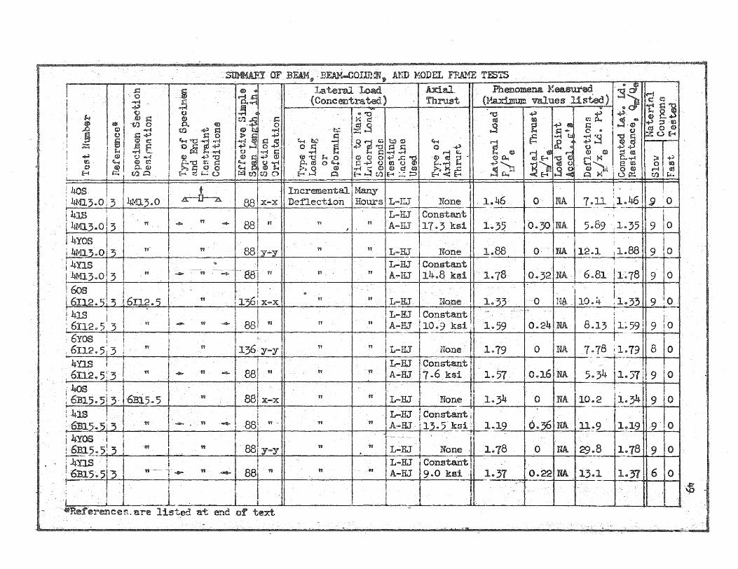
frames are summarized in the tables which are presented in Appendix Eo

15
BIBLIOGRAPHY
10 Howland, Fo Lo} iVStatic Load Deflection Tests of Be81D.~Columns, Y? Univo of 1110 Civil Engro Studies, Structo Reso Series Noo 65, Contract AF 33(616)=170, Deco 19530
20 Hall, W 0 J 0, uiShear Deflection of Wide Flange Steel Beams in the Plastic Range,UVUnivo of 1110 Civil Engro Studies, Structo Reso Series Noo 86, Contract AF 33( =170, Novo 19540
30 Howland, Fo Lo, Egger, Wo, Mayerjak, Ro Jo, and Munz, Ro Jo, HStatic and Dynamic Load Deflection Tests of Steel Structures, Ii Uni Va of 1110 Civil Engro Stuclies~ str'ucto Reso Series Noo 92, Contract AF 33(616)=170, Febo 19550
40 Egger, W 0 ,VINotes on the Analysis of Obliquely Loaded Beams in the Inelastic Range J
ii Univo of 1110 Civil Engro Stu.,dies, Structo Reso Series Noo 98, Contract AF 33(616)=170y April 19550
50 Wilkinson, CoLo, and Howland, F 0 Lo, iiTheResponse of Model Frames Subjected to Dynamic Lateral Loads,ui Univo of 1110 Civil Engro Studies, Struco Resa Series NoD 99, Contract AF 33(616)=170~ June 19550
60 WOjcieszak, Ro Fa J and Howland, F 0 La, liThe Response of Beam=Columns Subjected to Dynamic Lateral Loads, Ii Univo of Ill" Civil Engro Studies, Structo Reso Series Noo Contract AF 33(616)=170, June 19550
70 Howland, F 0 La, iiInelastic Behavior of Mild Steel Beams Subjected to Transverse Impact/v Univo of 1110 Civil Engro Studies, Structo Reso Series No a 106 J Contract .AF 33( 616) =170, August 19550
80 Mayerjak, Ro J 0, of the Resistance of Model Frames to Dynamic Lateral Load,iv Univo of 1110 Civil Engro Studies, Structo Reso Series Noo 108, Contract AF' 33( August 19550
9 0 Howland~ F 0 Lo J and Egger, W 0, iiCorrelati.ons of Reaul ts of Dynamic Tests of Beams and Model Frames~iU Univo of Illo Civil Engro Studies, Structo Reso Series NOO Contract AF 33(616) Septa 19550
100 Aug, Ao) and Massard, Jo Mo, Method for the Analysis of Frames to Inelastic Deformation into the Range of Strain Hardening J Ii
Univo of 1110 Dept a of Civil Engro J Techo Hepto to the Air Force Special Weapons Center -TR.-56=47)~ Contract AF 33(616)0170, Novo 19560
110 WOjcieszak, Ro F 0, and Massard) J 0 Mo, uUSlow and Rapid Lateral Loading Tests of Simply Supported Beams and Beam=Colu:rnns J Vi Univo of 1110 Dept 0
of Civil Engro, Techo Hepto to the Air Force Special Weapons Center (AFSWC-TR=57=21), Contract AF' 33(616) Febo 19570

BIBLIOGRAPHY (Concluded)
120 Egger J W 0' IV 6o-Kip Capacity Slow or Rapid Loading Apparatus, Ii Uni v 0 of 1110 Depta of Civil Engro J Techo Repto to the Air Force Special Weapons Center (AFSWC=TR-57~22), Contract AF 33(616)-110, June 19570
130 Hu, La So, Byce, Ro Co, and JohnstonJ Bruce GO}~IStee1 Beams, Coll.lilllls and F'rames, TI~ University of Michigan, Dept" of
Civil Engro) Engineering Reso Institute Projo M948, Report to Sandia Corporation, March 19520
140 rUBuilding in the Atomic Age,IU Proceedings of the Conference on, Massachusetts Institute of Technology, Dept 0 of Civil and Sanitary Engineering, June 16 and 19520
150 iUEarthquaj(e and Blast Effects on Structures) Ii Proceedings of the Symposium on, Earthquake Engineering Research Institute and University of California, June 19520
160 Clark, DoS 0' Behavior of Metals Under Dynamic Loading, Ii Trans 0 ASM, Volo 46, 1954, po 340
170 Hoff, NoJTo, 'iBuck1ing and Stability,VU Jo Royo Aero 0 Soco, Vo10 58, NoD ( 1954), po 30
APPENDIX A
ABSTRACTS OF TECHNICAL REPORTS PREPARED UNDER
CONTRACT AF 33(616)-170
10 Static Load Deflection Tests of Beam-Columns
by
F 0 L 0 Howland
University of Illinois Civil Engineering Studies
Structural Research Series Noo 65 December 1953
18
This report is listed as the final report for the period of 1 July
1952 to 15 September 19530 The work described in this report included a
series of static tests of beam-column specimenso These were lateral loadings
of beam=columns under axial load with the lateral loading applied in both the
strong and weak direction of resistanceo In addition some information was
included on the influence of axial loads on the response of beam-column
specimens 0 The report also indicates that a brief analytical study had been
mad.e of the effect of olJlique loading on beams 0
A total of nine beam=column specimens were testedo These included
two, 3 I sections, two 7 4 M sections and five, 6 I sections 0 Actually only
two of these specimens, one a 6 I and one a 4 M, were subjected to axial
load in addition to lateral loadQ The results of the tests are summarized
well in a series of three tableso
The effect of non=symmetrical bending including ideal plasticity,
(that is, the case in which yielding occurs at a constant stress without
strain hardening) is presented brieflyo The results are presented in the
form of an interaction diagram which relates the bending moments about the
principal axes of a section as a function of the maximum fiber strain or the
depth of yieldingo
20 Shear Deflection of Wide Flange Steel Beams
in the Plastic Range
by
W 0 J 0 Hall
University of Illinois Civil Engineering Studies
Structural Research Series Noo 86 November 1954
Methods of utilizing the reserve plastic strength of steel in
19
structural design applications have merited considerable attention in recent
years 0 Since deflections, rather than loads and stresses, often may be the
controlling factors in such design, it is imperative that it be possible to
calculate or at least make an estimate of the deflections under a specified
loading in the plastic range 0 A review of the literature indicates that the
discussions of the deflection of structures loaded beyond the elastic limit
have been restricted to bending alone 0 Little theoretical or experimental
information is available on the plastic defonmation of structural beam
sections in which high shear forces are presento
In order to study the deflection characteristics of beams sub-
jected to high shear forces, two continuous beams of 8 WF 58 as=rolled
section were testedo The main span of the beams was 9 ft and the overhangs
used to maintain the end fixity of the latter span were 4 ft 5 in. long 0
The central load points were symmetrically spaced at the one~third points
for the first beam. and at the one-sixth points for the second beamo Each
beam. thus had sections subjected to pure bending, bending combined with low
shear, and bending combined with high shearD Loads, strains, and deflections
were measured, and pictures of the whitewashed portions were taken to record

20
the yield patternso In order to made the pertinent data available to other
investigators, the load, shear, moment, and deflection data at key points
are tabulated in the reporto The detailed results of the tests are pre
sented in tables and figureso In analyzing the data it was assumed that the
deflections due to bending and shear could be separated and that their
combined effect could be obtained by superpositiono From the shear versus
shear strain data, a shear stress-strain curve was derived which can be used
to estimate the component of deflection caused by shear when regions of the
beam have undergone general shear yielding 0 As far as is known from the
literature} these tests represent the first large-scale tests of continuous
beams loaded far into the plastic range in which extremely high shear forces
are present 0 On the basis of these tests it is concluded that no measurable
reduction in the moment capacity (for the section and span used) was
indicatedo
The importance of the shear aspect and its effect on the behavior
of beams is evaluated brieflyo Theoretical examples are presented which
illustrate the effects of general shear yielding of the web on the deforma
tion characteristics of beamso This could be of major importance when shear
yielding of the web occurSo
**** A paper of the same title by W 0 J 0 Hall and No Mo Newmark has been
published as Proceedings Separate Vola 81, Noo 814 of the American Society
of Civil Engineers and a somewhat more condensed version will appear in the
1957 AGCE Transactions 0 The :proceedings paper i.s a condensed summary of the
data presented in the above report but in addition compares some of the test
results with current design specificationso Portions of the test results

21
indicate that where large shear forces are present the factors of safety may
be somewhat lowo This would seem to be particularly true for loadings of
the type used in these testso Since general shear yielding in the web can
cause excessive deflections, the recommended practice is to avoid high shear
when possibleo

30 static and Dynamic Load Deflection Tests
of Steel structures
by
University of Illinois Civil Engineering Studies
Structural Research Series Noo 92 Novet;n.ber 1954
Part one of this report presents a survey of the literature
pertaining to elasto-plastic and inelastic behavior of structureso
22
Part two describes static tests to failure of steel beam columns,
an analytical study of the effect of axial loads on the response of wide
flange beams, and the description of specimens, test apparatus, instrumenta ...
tion, and results pertaining to the beam-column study 0
The third part is a delPcription of model studies of frames
subjected to static lateral loads along with the description of the speci-
mens, the apparatus, the analysis used and the results of the testso
In part four the static oblique loading of steel beam columns is
described including the analytical investigation, the experimental investi=
gation and the summary of resultso
In part five the dynamic response of beams is discussed including
a criterion for determining the dynamic yield stress and description of a
dynamic test in a drop testing machine of one 3 I specimen including
instrumentation procedure, results and conclusionso
The conclusions listed in this report state that this program has
indicated that the static response of steel frames and frame elements can
be predicted with a theory that is similar to the elasto=plastic theory but

23
which includes the effect of strain hardening of the materialo However,
the tests have also indicated that the mode of failure can cause significant
deviations from the predicted response even though strain hardening has been
includedo For nearly all of the tests the experimentally determined capac
itywas between that predicted by the elasto-plastic theory as a lower bound
and that predicted by a theory that includes strain hardening as an upper
bound a In the weak direction of loading, although failures generally
occurred by local buckling and the load capacity was restricted, the re
sponse nevertheless approached the upper boundo In the strong direction
tests, however, the failures by lateral buckling cause significant deviations
from the upper bound predictions and, in many cases, the elasto-plastic
theory, which neglects strain hardening, provided the best predictions"
However, the deviation depends on many factors such as the restraint
conditions which are not incorporated in the theories at this timeo
In the application of these theories to the prediction of response,
the effect of axial load must be includedo In the weak. direction tests, the
thrust had only a small effect on the moment curvature relationship and had
to be included only in the computation of the applied momentso In the strong
direction tests, the thrust had to be included in the computations of the
bending moments and of the curvatures corresponding to these momentsa
The dynamic tests of the beam specimens have indicated that the
resistance to dynamic loads differs significantly from the static resistance 0
The change i.n resistance noted occurs because of an increase in the yield
stress of the material 0 This increase is, at first, a result of the delay
yield phenomenon which extends the elastic range of the responseo After
yielding occurs the resistance decays to a level that is greater than the

24
static resistance" The results of dynamic tests that were reported are of
a preliminary nature and continued investigation5J 6, 7, 8, 9, II has
produced a better understanding of the dynamic behavior of steel structures 0

40 Notes on the Analysis of Obliquely Loaded Beams
in the Inelastic Range
by
Wo Egger
University of Illinois Civil Engineering Studies
Structural Research Series Noo 98 April 1955
* The previous investigation of the static load capacity and
25
response of obliquely loaded beams in the inelastic range was restricted to
a small range of deflections by limiting the maximum magnitude of the
strains to the so-called Hflat H portion of the stress-strain relationship"
This restriction excluded the influence of the strain-hardening of the
material on the load-capacity of the beam 0 The e1asto""plastic theory
described in the report, though describing the behavior of the structure
reasonably well, was not suitable for a practical solution of the oblique
loading problem"
In order to overcome the limitation of the elasto-plastic theory
on the strain magnitude, the theoretical solution has been extended to
include the influence of strain=hardening of the material on the load
capacity so that the response can be predicted up to deflections of approx ...
imately 20 times the elastic limit displacement 0 It was f01.md that the
contri"bution of the strain=hardening to the load-capacity could be obtained
directly from the previous elasto-plastic analysis so that a minimum of
additional computation is required to extend the range of applicability of
the theory 0
* Howland, Fo Lo, Egger, Wo, Mayerjak, Ro Jo, and Munz, Ro Jo, "Static and Dynamic Load ... DeflectionTests of Steel Structures n Civil Engineering Studies, Structural Research Series Noo 92, University of Illinois, 19550

By means of the extended theoretical solution it was possible to
evaluate the applicability of the rigid-plastic analysis method by comparing
the response and load=carrying capacity of a cantilever beam. for various
directions of load applicationo This comparison has indicated that the
rigid~plastic analysis can be used to predict the deflection path with
sufficient accuracy except for the cases in which the load is applied at a
small angle to the web or Y=axis of the section.. Major differences between
the results of the theories occur in the predicted load-capacity since the
limiting capacity of the rigid-plastic theory is the Ii fully ... plastic Ii resist
ance for the structure which neglects the contribution of the strain""
hardening of the material to the load-capacityo

50 The Response of Model Frames Subjected to
Dynamic Lateral Loads
by
Co Lo WilkinsollJ and Fo Lo Howland
University of Illinois Civil Engineering Studies
Structural Research Series Noo 99 June 1955
27
The principal objective of this investigation was to determine the
inelastic resistance of model frames subjected to dynamic lateral loadso In
this studYJ the observed dynamic resistance of the model frames is compared
with the V~theoreticalVi and observed static resistance 0 This comparison aids
the eValuation of the parameters which determine the static and the dynamic
resistanceo A study was made of assumed forms of the dynamic resistance of
the frames on the basis of the relationship between the energy inputs and
the mac~imum deflections 0 This was a simple and convenient procedure from
which many of the trends of the dynamic resistances could be determinedo
Four model frames specimens were tested by subjecting each specimen
to a dynamic lateral load applied along the axis of the top girder 0 The
specimens were essentially ideal frames with fixed-column bases and column
sections which were one-quarter scale models of a 6WF25 sectiono The applied
loadJ accelerations, deflections, and maximum fiber strains were recorded as
functions of time during each testo
The dynamic resistance of each specimen was computed from the ob-
served loads, accelerations, and deflections by means of a single-degr~e-of-
freedom system analysis 0 The dynamic resistance curves of all frames had an
elastic slope less than the theoretical static resistance J but approximately

28
the same as the observed static resistanceo The dynamic resistance was
greater than the static resistances when general yielding occurred and
retained this increase until a deflection of from 8 to 11 times the theoret
ical static elastic limit deflection was obtained 0 .After this deflection
had been reached, the dynamic resistances closely approached the theoretical
static resistance for the remainder of the testo The increase in the observed
dynamic resistance over the theoretical static resistance has been predicted
reasonably well by consideration of the strain rates in the frame 0
Conclusions 0 The dynamic resistance of the frames tested in this
investigation was found to be higher at yielding than the static yield
resistance 0 After yielding occurred, the inelastic resistance approached the
theoretical static response and in the later stages of loading the dynamic
resistance can be considered to be the same as the theoretical static resist
anceo For large deflections, the theoretical static curves are a good
approximation for the dynamic resistance since the increase in dynamic
resistance at yielding contributed only a small amount to the total energyo
The dynamic resistance was found to be significantly higher than.the observed
static resistance since the local buckling and twisting of the columns, which
reduced the capacity of the frame in the static tests JI did not have time to
occur during the dynamic tests 0
Although these tests do not provide enough i.nformation to permit
determination of the response of any frame Jl they do give a general picture
of the response of frames and show what can be expected under conditions
used in these testso
6 a The Response of Beam-(blumnsSubj ected
to Dynamic Lat~ral Loads
by
Ra Fa Wojcieszak
University of Illinois Civil Engineering Studies
structural Research Series Noo 100 June 1955
The investigation of the response of dynamically loaded beam-
columns consisted of testing in a drop test machine four pin"" ended beams
with an effective span of 80 ina The beams were fabricated from 4 M 1300
29
rolled sections which were normalized to obtain 1llliform material propertieso
One p~ir of the specimens was tested in the strong direction while the other
pair was tested with the section oriented in the weak direction with respect
to the appli.ed lateral loado One specimen in each pair was subj ected to a
constant axial load in addition to the dynamic lateral loado
A test consisted of dropping the 500-lb weight of the drop test
machine from several heights to vary the energy inputo In each test the
lateral load, deflected shape of the beam, strains, and axial load, if
present, were recorded as functions of timeo
The test results indicate that increasing the energy input
increases the duration and amplitude of the load, and the maximum deflec-
tiona In general} the axial load did not appreciably affect the resistance
to lateral deformation of the beam-columns oriented in the strong direction
when the center deflection was small, approximately less than three times
the static yield deflectiono For larger deflections the axial load had the
effect of causing the response to decay toward the theoretical static

response curve and the resistance of the specimen was often considerably
less than the resistance of the specimen without axial loado With the weak
direction specimens, as was expected, the resistance-deflection relationship
was affected more by the axial load than was the case in the tests of the
specimens with the section oriented in the strong direction~
The correlation of the dynamic resistance to lateral deformation
with the theoretical static resistance was obtained by comparing the actual
energy-input and maximum deflections with the strain energy predicted from
the theoretical static resistance-deflection relationship at the same
deflectiono When the energy input at the maximum deflection was gr'eater
than the corresponding strain energy predicted using the theoretical static
resistance, the yield stress used for the static resistance deflection
relationship was increased until the strain energy approximately equaled the \
energy input measured in the testa
.By comparing the energy=maximum deflection relationships obtained
from these tests, it was found that higher values of the yield stress were
required as the energy input increasedo It was also found that the axial
load had little effect on the resistance in the deflection range from
approximately zero to three times the static yield deflectiono However;1 for
larger deflections the axial load caused the resistance to decrease with
increasing deflections in the same manner as was noted in the static tests
of beam=cplumnso In the case of the weak direction specimens the increase
in yield stress with increased energy=input was smaller than noted in the
strong direction tests p

70 Inelastic Behavior of Mild Steel Beams Subjected
to Transverse Impact
by
F Q L.. Howland
University of Illinois Civil Engineering Studies
Structural Research Series Noo 106 August 1955
The response and resistance of a dynamically loaded mild steel
beam has been approximated using a single-degree-of ... freedommodelo The
resistance of the beam and model has been considered to consist of the
following phases~ (1) an initial elastic resistance; (2) a subsequent
31
inelastic resistance whi.ch may be a function of the displacement, velocity,
and time; and (3) finallYJ a recovery resistance that is essentially elas~
tico The elastic phases of the resistance are fUnctions of the displace-
ment only and1have not been considered in this investigationo
The initial phase of the inelastic resistance of the model was
found to be a function of the velocitYJ the time:! and the static elasto-
plastic resistanceo This time-dependent resistance has been assumed to be
given by the following expression~
where w and R are the rate of change of the displacement and resistance,
respectively, with respect to time; K i:s the elastic spring constant; R is
the resistance; and Rfp is the static iifully=plastic H resistanceo The
time-dependent resisting function is applicable until the time when it is

32
equal to or less than the static resistance, which includes the effect of
strain-hardening of the materialo
From the information in the literature, and from a consideration
of the static inelastic deformation process, it was found that the parameter
a could be expressed as follows~
aKT
where u g is a dimensionless velocitYJl T is the period of the beam, and f3, C,
and n are constants 0 The constant f3, which is determined by the load
distribution along the beam, relates the velocityu V to the maximum strain-
rate 0 Because of the derived form of f3, the time-dependent resisting
function is restricted to statically determinate beams" The constant C is
essentially a dynamic shape factor 0 Both C and n are determined, in part,
by the relationship between the lower yield stress of the material and the
strain-rate"
The applicability of the procedure was investigated by predicting
the response of several beams and frames for known loads and comparing the
predicted response with the response measured in testso This comparison has
indi.cated that the magnitude of the derived constants are essentially correct
but that further adjustment of the constant f3 is necessaryo
From a brief study of the time""dependent resistance, an a:pproxi-
mate method has been outlined for estimating a dynamic iYfully .... plastic H
resistance to replace the more complex time-dependent resistanceo
Two additional investigations are included as Appendices~ (1) A
criterion for estimating the dynamic elastic limit resistance and displace-
ment of the structure 0 This criterion is based on the available information
Room . . .4 ng Department Civil Engineer ......
BI06 C,E. BUlld~ng . • .l-~,. of TIllnolS
UniverSlllJ -;LllinoiS (;
U,1;;~~'.lU

33
concerning the delay time for yielding 0 (2) A semigraphical procedure for
including the effect of strain=hardening of the material on the static
resistance and response of inelastically deformed structureso
Summary 0 From this investigation of the inelastic resistance of
mild steel beams subjected to transverse impact it has been found that~
10 in the early stages of the inelastic response J the resistance of mild
steel beams exhibits a defi.nite time dependent character; 20 when the
displacement of the beam becomes sufficiently large, the resistance of the
structure is the static load deflection relationship for the beam if strain
hardening of the material is included in the stati.c analysis; 30 if an
inelastic resisting function for the beam is assumed, the parameters requi.red
in the function can be derived from the information available from the lit ...
erature and by considering the static elasto=plastic behavior of the
structureJ 40 from a study of the inelastic resistance during time dependent
resistance portion of the response, an approximate procedure for estimating
the dynamic fully plastic resistance can be developedo

80 A Study of the Resistance of Model Frames
to Dynamic Lateral Load
by
Ro J 0 Mayerjak.
University of Illinois Civil Engineering Studies
Structural Research Series NoD 108 August 1955
The resistance of model steel frames subjected to dynamically
34
applied lateral loads which produce large deflections (nearly 30 times the
elastic limit deflection) is studieda The results of static and dynamic
tests are presented. These provide a basis for the comparison of the
dynamic with the static resist~Jnce of model frames a
The models used in these tests were made from ASTM A=7 steel and
were machined to be approximately 1/4 scale replicas of a standard 6 WF 25
sectiono In all of the tests the sections were tested in their strong
direction of resistanceo There were two center loaded simple beam tests;
one third point loaded simple beam test} four rigid top girder frame tests}
and six flexible top girder frame testso In two of the flexible top girder
frame tests:! axial loads were applied to the columns of the frames in addi-
tion to the lateral load. The rigid top girder frames were square bents
approximately 15 ina by 15 ina The flexible top girder frames were rectang ...
ular bents approximately 1665 ina high and 30 in6 long 0
The experimentally determined resistance functions for the frames
tested in this investigation are in good agreement with those theoretically
predictedo It was found that the characteristics of the resistance function
for dynamic loading conditions can be explained and predicted by taking into

35
account the dynamic stress-strain properties determined from investigations
of tensile coupons of a similar materialo
Relationships for estimating the resistance function of full sized
structures subjected to dynamically applied loads are developede Tb~e proce
dures are based on dimensionless relationships which enable one to determine
the angle change in a member subjected to large inelastic deformations. When
this is done, the load-deflection analysis can be made by conventional
procedure~.

90 Correlations of Results of Dynamic Tests of Beams and
Model Frames
by
Fo Lo Howland and Wo Egger
University of Illinois Civil Engineering Studies
Structural Research Series Noo 109 September 1955
The object of this program is to determine the effects of blast on
buildings and structures by investigating the load capacity of steel struc-
tures and elements under both static and dynamic conditions 0 For a static
load the load capacity can be obtained in the form of load-deflection and
moment-curvature relationships for the structure 0 When the structure is
loaded dynamically, the resistance or load capacity no longer is a function
only of the deflecti.on but can depend also on the strain rate and possibly
the time 0 Thus, a second objective of the program is the correlation of the
dynamic and the static resistances 0
Previously the emphasis of the program has been concentrated on
investigations of the static resistance of steel structures 0 The results of
these investigations have been summariz.ed in the report which is the final
report of the program for the period 15 September 1953 to 1 September 19540 3
These studies have indicated that the static resistance or load-deflection
relationship can be obtained by means of the available theory of plasticity
if the influence of strain hardening of the material is included in the
analysis and if the structure does not develop a lateral or local failure
during the loading process o. A limited study of two aspects of the static
response problem has been included in the present contract and the results
of these studies have peen distributed as technical reportso The first of

37
these investigations is concerned with the influence of strain hardening of
the material on the response and resistance of obliquely loaded steel beamso
The second investigation was a study of the effect of combined bending and
shearon the resistance and .deflection of steel wide flange beamso Abstracts
of these reports are included in the appendix 0
The major emphasis during the present contract has been placed on
the investigation of the dynamic resistance of :mild steel structures o The
determination of the dynamic resistance and the correlation of the dynamic
and static resistances for various structures have been studied by both 0
experimental and analytical methodso In the experimental studies, several
types of specimens have been tested under a variety of loading conditions 0
The results of the various experimental investigations have been reported in
references 5 through 80 Abstracts of the contents of these reports are
included in the appendix 0 The information obtained from the various experi
mental investigations has been used~ 10 to determine the dynamic resistances
for the structures; 20 to determine the variations in the form of the dynamic
resistance; and 30 to provide experimental data for use in checking the
applicabili ty and validity of the methods of analysis that have neen developed 0
From the results of the tests it has been found that the dynamic
resistance of a structural element can differ appreciably from the static
resistanceo
The dynamic behaviors of test structures were analyzed by assuming
that the actual test structures could be approximated as single-degree-of=
freedom systems 0 Roweverj slightly different approximations to the form of
the dynamic resistances of the structures were made by tne two principal
investigators, Howland and Mayerjako

Howland assumed that the resistance of the structure was of an
elasto=plastic nature similar to the resistance of mild steel to uniform
axial deformation if the upper and delayed yield effects are neglected but
dependence of the instantaneous resistance stress upon the rate of general
yielding is retainedo After general yielding is completed and strain harden
ing begins, it is assumed that the dynamic resistance is the same as the
static resistance 0 In the formulation of the resisting function, parameters
were included to take into account the distribution of load, the boundary
conditions} the shape of the cross section of the structural element} and the
material from which it was madeo
Mayerjak based his computations on the stress .... strain relationship
for the material rather than the overall resistance of the structure 0 The
dynamic increase in resistance was taken into account by increasing the
stress level of general yielding in accordance with the average strain rates
expectedo This procedure is fairly accurate since the relation between the
stress level and the rate of general yielding for mild steel is relatively
insensitive to changes of strain rate no greater than one order of magnitude)
a range which includes the average strain rates encountered in the testso
Using the dynamic stress=Etrain relationship} Mayerjak computed
dy-namic resistance deflection relationships for his frames by the same general
method useo. in obtaining the static load ... deflection curves if inertia effects
are neglectedo This procedure is not restricted to statically determinant
systems or those which can be approximated by single-degree-of-freedom analogso
Howland later modified his procedure to a simpler approximate method
in which the general form of the dynamic resistance function for the structure
is the same as that for static loading except for an increase in the iLevel of
the fully plastic resistance 0 This level is determined by a consideration of

39
the elastic response of the structure as compf'ed to the dynamic resistance
computed using the. velocity de~endent relationship of Howlandis first methodo
The approximate method Was used to compute values for the dynamic fully
plastic resistances of the specimens as they were tested with their various
loadings 0 These results are compared, with the values of fully plastic
resistance obtained.by tests in which the data are interpreted on the basis
of the single-degree-of-freedom analogo
Conclusions 0 Comparisons of the specimen resistances obtained
experimentally with those computed using the approximate method indicate
that~ 10 The ratio of the dynamic fully plastic resistance to the static
fully plastic resistance is not changed appreciably by the changing of·~the
orientation of the cr'oss section) span of the beam, or shape of the cross
section" (This indicates that the increased resistance is a function of the
specimen material and not the conformation of the specimena) 20 For the
tests considered, the dynamic fully plastic resistance can be related to the
static lower yield stress of the materiald (This indicates that the actual
critical strain rates occurring in the test structures were of the same
order ofmagni tude or else that the material is relatively insensi ti.ve to
changes in strain rateo) 30 The addition of a constant axial load did not
change the total internal resistance of the structure appreciably from the
value it would have had if not~rust were presento
Major differences in the form of the dynamic resistance deflection
relationship were noted when the resistance of the determinant and the
indeterminant structures were compared 0

10. A Method for the Analysis of Frames Subjected to Inelastic
Deformation into the Range of Strain Hardening
by
AoAng and J 0 Mo Massard
University of Illinois, Department of Civil Engineering Tec[J.nical Report to
The Air Force Special Weapons Center (AFSWC-TR.,.,56=47) November 1956
A method for determining the resistance of frame structures
40
composed of elements having individual resistance-deformation characteris ...
tics of any monotonically increasing form that can be described graphically
is presentedo The resisting moments in a structure which correspond to a
given set of displacements of the loaded joints are found by a trial and
error procedure made convenient by use of moment-end slope relationships
for the individual memberso After the resisting moments have been obtained,
the corresponding set of loads required to produce the particular joint
displacements are computedo
By solving a set of such problems.1 load.;.joint displacement
relationships can be obtained for a range of loads:; or conversely for a
range of displacements"
The general nature of the method is such that it is perhaps most
useful i.n research applications 0
A simplified procedure for the analysis of independent frqrnes
using moment distribution with bilinear approximations to the moment-end
slope relationships is presented in the appendix 0
The pr'ocedure used in this report involves assuming displacemeIl,ts
of the loaded joints (the general deflected shape of the structure), and

41
obtaining the resistance of the structure to that particular deformation
pattern assuming that a reversal of strain does not occur any place in the
structure 0 The practicability of the method depends upon a convenient
means of relating the resistance of a member to its deflected shape" In
this method, the resisting moments at the ends of a member are related by
graphical representation to the end slopes of the membero Using these
relationships (which apply to any wide flange section within the limits of
error given below) resisting moments can be found for the assumed deflected
shape of the frame structure using an iterative trial and error procedureo
After the resisting moments have been found, the combination of loads that
could produce the assumed deflection configuration of the structure can be
computed 0 The moment curvature relationships presented in this report can
be used with an error of less than ± 3 % in the resisting moments for all
structural wide flange sections"
Neither 'of the methods presented in this report takes into
account the effect of non""rigid connections on the behavior of the frame
consideredo It is expected that the procedures will be extended to include
this effect as a part of the work in the Contract AF 33(616)""37800
110 Slow and Rapid Lateral Loading Tests of Simply Supported
Beams and Beam-Columns
by
R. Fo Wojcieszak and Jo M. Massard
University of Illinois, Department of Civil Engineering Technical Report to
The Air Force Special Weapons Center (AFSWC-TR- 57-21) February 1957
The two major purposes of the program described in this report
were to determine experimentally the resistance of beam and beam-column
specimens to inelastic deformations applied slowly and rapidly; and, if
possible, to correlate these resistances with the static and dynamic
properties of the material from which the specimens were made.
The results obtained indicate that, beyond the static elastic
limit, the resistance of a mild steel beam or beam-column to a lateral
displacement produced rapidly is greater than that corresponding to the
same lateral displacement produced slowly, and that the increase in the
42
resistance of the beam with the rapidity of the lateral deformation can be
explained with an experimental error in the limited range of strain in
which comparisons were possible, by consideration of experimentally deter-
mined dynamic properties of the specimen material which included delayed
yielding and rate of general yielding behaviors typical of mild steel.
The experimental work described in the report includes the deter-
mination of the mechani.cal properties in the specimen materials, the
determination of the residual strains in the beam specimens, the beam and
beam-column investigation which included a total of nine individual specimen
tests and a correlation of the beam resistance with the material propertieso

Conclusions 0 ao Beyond the static elastic limit, the resistance
of a mild steel beam or beam-column to a lateral displacement produced
rapidly is greater than corresponding to the same lateral displacement pro
duced slowly 0 bo The increase in the resistance of a beam with the
rapidity of the lateral deformation can be explained, within the limits of
measured strain anp. .experimental error, by consideration of the delayed
yielding and rate of general yielding behavior of the specimen material
corresponding to stress-strain-time conditions comparable to those produced
in the beamo co When under a .constant axial load, the resistance of a
beam-column specimen to a rapidly or slowly applied lateral deformation is
less than that of a similar beam without axial loado do A beam which is
tested slowly with increments of displacement W'ill have a resistance at any
inelastic displacement less than that exhibited by a beam loaded slowly but
continuously 0 eo The delayed yielding and rate of general yielding be
havior determined experimentally from the coupons which were cut from the
structural sections tested were comparable to those that had been obtained
at the University of Illinoi.s and elsewhere for mild. steela
Time did not permit a correlation of the slow and rapid loading
behavior of the beam-column 6pecimens with the properties of materials from
which they were made as was done for the beam specimenso However, the
authors believe that, as in the case with the beam specimens, the differ
ence in slow and rapid loading behavior could be explained in terms of the
stress-strain-time properties of the specimen materialso
Even though the scope of the investigation, at least as regards
the beam and beam-column tests described in this report, is rather limited,
it is believed that some procedure of determining the dynamic resistance of
a structural element from considerations of the dynamic properties of

44
the material from which it is made is generally applicable to problems of
determining the response of steel frame structures to conditions of loading
or deforming that vary in time from slow or static conditions to those in
the range which structures of this type might be expected to resist under
atomic bomb attack or earthquake shocko
120 6o-Kip Capacity Slow or Rapid Loading Apparatus
by
Wo Egger
University of IllinOis, Department of Civil Engineering Technical Report to
The Air Force Special Weapons Center (AFSWC-TR-57-22) May 1957
In this report is described the design, construction and opera-
tional characteristics of the 60-kip slow and rapid loading units developed
at the University of Illinois under Contract AF 33(616)-1700 The desired
operational characteristics of the units as described in the contract cover ...
ing their construction were largely met by the units as completedo These
were~ that it be possible to apply a loading either slowly or rapidly of a
magnitude oft 50 kips; that the units have maximum stroke of 18 inches;
that it be pOEfsible to apply the maximum load in a time on the order of and
if possible less than 10 milliseconds; and that it be possible to release
the load in a controlled time of approximately 30 millisecondso In the
report the actual load versus time relationships obtained through the use
of these units are compared with load time relationships which were obtained
from thermodynamic considerations of the mass rate of flow of the gases in-
volvedo In the region in which the theoretica:].. relationships are applicable
the agreement is quite goodo

APPENDIX B
TABULATION OF TESTS PERFORMED UNDER CONTRACT
AF 33( 616) -170
The values presented in the Tables were obtained directly from
information given in the report listed as the ret'erence" In some cases
where the same test information was used in more than one report minor
discrepancies may be evident.

Notation
TABLE OF NOTATION FOR
APPENDIX B
The following notation has been used in this appendix~
NA
NR
P m P e
~ Qe T m T e
x m x e xx
yy
Loading~
A
L
Loading Device~
C
j:.1
HJI
PJ
S
W
20k
60k
Not Applicable
Not Reported
Maximum Applied Lateral Load
Applied Lateral Load which Would Initiate Inelastic Behavior with No Axial Thrust
Maximum Lateral Load Resistance
Elastic Limit Resistance
Applied Axial Thrust
Axial Thrust which Would stress the Entire Cross Section to Yield
Maximum Center of Span Deflection
Center of Span Deflection Corresponding to Yield
Strong Direction Orientation
= Weak Direction Orientation
Axial
Lateral
l20k Baldwin. Machine
3000k
Machine
Hydraulic Jack
Pneumatic Jack
Springs
500-lb Drop Weight
20k Slow or Rapi d Machine
60k Slow or Rapid Machine
47

stJMMARI OF EFAMil l?EAM-COIDHN, AND MODEL FP.AME TESTS • -- - -- III> e 1 ! s:: i .. · Lateral Load Axial Phenomena Measu.red :3 a .-t
I .~.. ct~ (CofIcentra~J ..'l1i~t (MaJdJDuIn values. llsted, 1 ~ ~ ~ ~ ~ . "f"'4 S _ ,~ III cF ~ PI I). . I 0 v ~ 4 • ~ *tj ~ ~ ~. f) R+l
I ·~ @) ~ t) til ~ J:: ,x d 4!IS ~ !Ill C'4.. ......,.-.1 'es:: • til 0 Q.. Ii cod , '+l . ~ ~ ., , rI
I .! ~ I ...... til ~ ~ t) O?J ~ . ~ S ,~~ s::: ~ C" . 0 ., 0 (!) () ~ S:::o ~....,. t:; -4' ~ "0 XOf-:t ~ c i ro ~ "C ...,.. ert "" i~ s:: ~ c..... b.O ·r-!O rj ,&:l .tlO CD «t-4 i.t: 0 ~ +>:9. I C1J 5
:;!:O t) S C '0 C ~ ~ +l ...:to -+' 0 s:: C! +> 5O!O s::: s:: 0 +l p... 0 ~ ~ '-a .... L M f.4.cr« 0 ...-4 ~ .... ~ . H .s:: erl ci-f r-! cr. ~'H til tD m ' , ~ I!tl
~ G) (l . .....c III) ~ "d •.. +' C'D 41)'''0 s.. a c)Cl.l 0 +'..G "0 C> G:! :::s C) p... ''«:3,'~ ro r-l ~ ! o..~ ;,t ~ m ~ G) m ~ &Ii ~ ~ U "f"f ., 0 ~ g ~ 0 fiQ () II) .,... ~ +' ~-" @15 d 10-4, S m 0 f'l I w .. ~ .. I ~ ~ ~ 0 ~ . 0 ~ e; 0 ,.«> ...-! ~ «> m tj me ~ k rF! I ~ ~ tf'~o.ai .. ~\ O'l) ,II rll. Qj I E-t ~ to Q 8 ~ c:. U C::l tf) ttl O. E-4 H ,.A f---.. 1-4 tJ) _E-t ;..;: ::::> ~ -< t;-o 1 ~ A.a -< f-4 .....l ~ c:. x 0 P::: tt) I ~
~-'l-------l --, t, IIIncremental! Ma.n~1 JL'I,. , I,.! +1' I 1317•5 ,1 317.5 ~ ,1 x-x' flection l!lour L-HJ None, 1.29 0 NA--J-2,.9~8,2;,_1 .. 29 -<7,_~' 1205 ! I I I! I I 'I I! I lID-.5 i 1 I IDe5 .. I 401 x-xli " !" I "i .. II 2.21 0 I NA kr~~21 7~ !6Os' I I . i ! II I:·! ~n2. 5 i 1 fU2.5 "11361 X"X .. ! n .. .. [I 1.34 0 i NA J.O'~---.;2:..34; 9 I 0-l i20S I I ' , I! [ 1 I . ~.5 : 1 i" .. i 40! x-x,1 .. I" I"+," 111.99 1. 0 I IV. ;29. 4 !1..:9911 91 0
1425 :! 1 t I ! II.. 1 I L-HJ I Con~tant;j I I: : .._ ;6Il2 .. 5: 11 " :~~---l Be1 x-xl n ! n A-HJ 10 .. 0 ksil 1 .. 59 10 .. 26' NA i 8 .. 13 : 1,,5911 910
i6Yos il I ~.. I . I I . I !,: l6112 .. 5 11! n ~ 1~ y-y If tv L-HJ None 1 .. 82 0 NA P.O.4 11 .. 821 81 0
12YOO· ! I . I I·' l6I12.5 ,1 n n 40 y~y, .. .. .. " 2.51 0 NA 22.9 2.51 810 1=3.0 11 lOO3.0 n 88 x-x n " n .. 1.64 0 NA 7.02 1.64 9! 0 ,4].53 \1 . t ·L-HJ Constant \ ': :4MJ.3 .. 0 ~ " ~.s=-O--a"'" 88 x-x n 99 A .... HJ i6.6 ksi! 1 .. 35 0 .. 32 NA 5 .. 89 1.35 9 0 r I !
I f
+ (l)
NA 22~8 'I '
0 NR 9 0
,---i i B-1 I
.2 I BWF58
I f-
• ~ ~ tl- Incremental. Many A a NA x .... x
99 I 9 1 0 0 NAf.Q~- NR
8; " H :1 .. 38 t 0 INA JIB .. l . 1m I .L-~ l ,0
,f t -+ + I NA x-x Ii'II " I 7s: JI
1 + .. NA " " J1 :a x .... x
1 I
T I .
! .:B-2a .~ 1 2 "
B-2b I 2~ n 1 1
·References are listec nt end or text (1) .p .... bas~on beginning of general. shear y1el~ ..
stMMAF.:I OF, BEAMt.BEAM-COlnHN~ AND lviODEL FPȣE TES'TS
s: '0 ~ .., () .. .ID &:
'ltl::! 0 Q ~ «:) s::+> § 0 e
I ~ I !l E. ¥ I "'I ,,~ I ~ "'-' (Dr!: ID m Q...Cl> I
f:-I ~ tf.j 0 I I I' I
40s I I I. 4Ml3.0" I~~:;$O I
\ 415 I 1_~~3.,O~3 14yOS i 1100..3 .. 013
" u'
" !..4Y1S
1.4Ml3.0 I 3 .
1~2. st L6!)2. 5 r 141S I ; 6I12 .. 5, :; : 6yos .6112 .. 53 -, 4n.s . I 6n2 .. 53
1t
tv
'IIY
j40S ,l ; 6B15 .. S!3 16]3].5 .. 5 I4lS ! : ·61U5 .. 513 . i 4YOS! I i 6Bl.5 .. 5' 3 1 -' -.--~
~
. .,..
I
!
:~ .(; ~ ()
ID £: A ~ 0
W ~~ J:!o
'"'C ,"1"'11 eM
t5 'f,~ ~ ~ '''0 f;; ." ,t;'~ s:: ~00
£-io::~O
t ~ I 88!X-X
.. 1"
1t
..a.. 1ft
iV
....... tv
tV
... 1'3
1t
- .. n
ft
- I 881 " 886
m ~+-88:1 n
t I
,136: x-x I
""'- 88' 'IV
l:;6:y-yl 1
. I ~ I B81 'Wt
f 88!x .... x I
I ~I 88i ff
. 88 y-y ! j
T-IIP fl ~ 88' " 1.4Y1S '·1 '6B15 .. s13 1\1
~ ~-I
j , ., Lj
.' '-References. nre listed at -end of' terl
.Lateral Load (Concentrated)
4"'0 X d .... ~ I$S
~ ~ ~. ;~~ if~ ..r! s.; I s.:4 S:;::...-I.....-t
ID"t:! J.., 0 ID 0 o+=..c"'d p...a:lo~ '[:+>01:001'1')
~~ Q G.l.1 """" ,~ CD, ro, d III 8~ 0 E-<~tr.!E--.::"::::::>
Axial ThI"l.lSt
4-4 o +'
.-1(.'.. ID cd !';S ~
t.:;... "ri "'" ~"x ..c 8<8
Phenomena '}~easuroo ':3 -:1 e-f
(l~ valueslfsted) ~. .c:: t':i ",CF t! ~ 16
'"0 ~ -+l +'b' <0 $2, ~ ~ m . r::: (.A.. as &. • ..,:::;- ,we o !:.1 ¥ s::: ~'m"- ...... " ~ ~ ~_ CO., I o .. ~ C2 CD
~ ~ £' t :s $ ~ ~ uf-i
~ (l) rl m Cl ::1 m (!) ~ m E--. "0 rl ~ C-."rI ~ I ~ +> ((j 0 c...... E f1.l 0 Vl Ild~ 11~o Q~'Oa> r-I m ~p.., . <~...:J QX O~ til ~
I'~I l.,46 I 0 INA I 7 .. 11 ;10461 S) :0
3~ 10.)0 iNA I 5.~9-;1~35 9 10
'Many Increme~taJ.1 Hours I L-l1J None ~. DefiectJ.On .. .L-:sJ consta.n~
n A-ill 17 .. 3 ks tv
T I
" n 'L-RJ I None 1 .. 88 I 0 IliA 112 .. 1 i 1 .. 88 9 ! 0
I .. 78 f O.32INA ! 6,,81 11~ 78 9 10 . I
1 .. 33 10 ! Na .\10.4 11 .. 33119! 0
L-HJ Constant
" IA-ro ].4 .. 8 kef
n L .... ID. Hone
n
n
L-RJ I Constant 1- . 8.13 11 ;59!1 9 \0 .. IA-F.J i 10.9 ks! ,I 1.59 0 .. 24 NA ~~' .
" IT HJ . l' ' 1 79 o UA 7 .. 78 11 .. 79 II 8 I 0 i .L,u- lone G . '. I . . .. ~ '\ '
L-HJ I Constant. n' I A...;HJ 7 .. 6 ksi I 1 .. 57 o,,16NA I 5 .. 34 11 .. 3719 jO
:' I I n I L-m! . None 111.34 ! 0 INA Ilo~~.34119 10
L-HJ r Constant i
: ;:~:r3·;o::~I! :~:: 1°:361: I::: 1:~~:II:I:
L-HJ ! Constant I .. I A-HJ 9·0 kS~1.37 .. /o.22INAI13.111.371161 0 I I . ... . ... I··· . I ~
.l.
rr
ft
n
n
1'1
n
~
m _~.l.

Ew~-cornEN~ Al~D MODEL FP~1E TESTS
r- r ,. 1m J Lateral Load Axial. Phenomena :s,:J M
g:l~1 (Concentrated) Thrust (Haximum vaJ:ues@:;' .~ ~ 15 !l~ <»"0 "'d ~ +> +> ~9 § I 8. ID CJ :S§ t.; 2 ~ ~ +> ~ ~ ~. ~ ~ ~.~
ID I ~ I m ~ ~ (!) ~ t:; ;:: ~ ~ ~ s:: ... c.. () $ .. ~ r~ o ~ ¥ I ~ 0 i> ~ ~ b::: ...c eM .'. crl 'U "0 5 <J"-<l ...... n;,-"
eO t:: I '-'" "'T"t.-r. sM ru's;;:.s I c..... ~ ..,..-l .O·.-j Qb.O .. i:D . r-i b 0 +J ....J C) .:3- I--.....,-~ $... I' !i E I O~' f ~ "6 ...:11 3 r;:: 0 !l ~ 1
1
' +' ~ wg ~ ;.1 11"""1 ~ ~ ~ 0... ~ m ~ t!fl
Q 0 ...-f r 0 .+-1 "0 ID ~+' lD O"d NO. CD 0). 0 '+'. ..c; "0. ID iJ.\l .~ (!) A.a ~ 8 "dri X .r-.... -ri 11 ;:: \ .p-ro Ilf.: I p..."O ff.j ~ .c....:. 0. "'rill p.. d O·(;.;,i , E: +' Q1 UlO (0 P..,,-I ~ +J..........] ........... \ ~ 0 c..... "'" S \1.l . 0 ID Q. ID ~ t:l CD (:) ~' • ~ .;:-. q m I..,...;'" (j) «>'!;j OJ i :> .. }Ii ..s:::: Ilt1 ~ ~ 0 0 iD .. ~ 0 0.> rl Q'j
til Q 8 crl h {,) a:il tfJ· 'Ell 0 f:-4 ....... Q b ;:t tr:l E-.; :..: :::> I f-i" -< f-i ....:t (l;., . [-I ...:J -< Q X (.) P:: c,'l I ;::.....
I Frame~! 12/4 sell ttl jll··Incremental! I' 1111 I Beam 1.: 3' 16'WF25 j..iii A INA. y-y II D~nect~'2n Hours kC Nc~ne I Frame I I . I I +-.... . I E. e. ~a 7: 3 ~, I ti INA .. I x-,x n n L-C n . .l.., I Frame i ! ~. I I
"Beam 4, 3 ,,! -" t A T5 i y-y " lUi I,,-c In! i ! ! ..! I' I
iFrame I' I .. , 1 I I t-=,·-'t I
I Beam 613 1 Wi I 111 15 I x-x " .1 tt L-C. . ... 'v. _ ... _' .. '.. c:. i---' ! I I ! 'jl 1 I .1 . I:
: I I I ., I' i -V .. 3 I 4 i 0 , I
!1" 4 '0
I I l .. 7511410
~OTNA ~ 70
I I
1 I
0 NA ; 140
tO~2 0 NA. 90
!hame Incremental: fl· I ; 1 Deflection I Hours! L-FJ None I 3 .. 3
i---- .
iFrame ! I' ! I : I .
2 ! 3 '" 115 I y~' ! "n 1" 7 Fr I I i
i arne I F9-! j
_,3 1:2 j n l·~ 115 l x-xl " n None II 1 .. 15 Frame I i I II' I L-EJ I Constant Ii ;~
4 ~ __ , " t15 ,x-~·_ it n J A-S j8" 73 ksill 1.,45 0 .. ;23 NA 9Q. 1,,4511410
1 '
1- ... . I' -----n I I I! /l L ______ ~,l" "
i4XYos T I 'I 1 ·11 Increm.entaJ..1 Many ·1· -.,' II . I .' I , - 1 . .11
j'
! 6B 3 !6B15 .. :5 -, 87 45° Defie,ction Hours L-HJ None I 2 .. ,3E) .... /0 NA 39 2 .. 36 1130
4ms I rt t I I II L jL-HJ Iconstantll I I I ·II! I l t
1
6B 1~316B15. 5 l-.A --u--,.-, B7 ! 41' .. ." I" f A-ilJ ,10 ksi ;. 1.64 "0. 25. NA . 23 11.64 13 0 ~ 'I 1, . I
·Reference~· are "lis+ c.:atetld·of terl

51 ," _pe'+Syl ':pnij 0 0 0 0 I---~ 0 0 0 0
t.:uodnoJ ---~---,---.-- ... ---.. -- --- I-- --- -----~-- --I~O"(S
t ul·.H~,+ u~'l , "" r<'\ t<\ ,.., t<\ t<\ 1'<" t<'\ 1<\ \
~
9~~ , a ~Uly.p:n:S 3U
r~-~--: ~ ~ ~ ~- ~ ~ ~ 4IP'1 ~t?J p9'tnJmo~ -.,- .. -.- ~ .. -- - .---_ .. ~ ----- -- ---'-.-.. : at (\j C\.l IJ'\ lJ'\ lJ'\ 1<\ 11 ~1-d GP1 x x t<'\ t<\ ,0 0 0 0 -g; co (\j
'i~ G tiO T'l oe lJaQ ril 4> G " .. . FI • G
rl ,(\J (\J t<\ "', -=.t \.0
~;q A
.'~"fIITaooy ,
i fI.l ~ ~ f§ ~ ~ ~ ~ ~ ~ (l) '·Pll0d PliO, ~::;
.9 l!"l' ~i t~N4J, pp::y 0 0 0 0 0 0 0 0 0
~ § I
~j ad!ld co co (\j !
(\j S 0 erR co 0'\ 0\ lJ'\ IJ'\ 0) -~ 0
p'OOJ TlJJ:v,+VI 0 1 . e e <II " 0 • 0 rll rI rI ,.... (\J (\J .-. p
~
I .-I- --~-.-~. ~ .- f-;--' - ..
+l . t ti n.z lil i i "
~~ p:q:xy Q)
I::· ~~ JO adAJ. ~ 0 :: :: :: :: ;: ;:: ... ~
----'--.. --I ,...--~sn
~ ~ Otq: qou:·! • ::: :: .... :;: ;:: ~ • ::
:JU1'lSa.L H H </"""II. -- f---. -~ ... - - ---1--'0-- f-.,-:--- f-.•. - ....... ~-----
~] ;~puooas IJ'\ 1.(\ 1.(\ U"\ ~ ~I" ~ t<\
t(\ t<\ r<\ r<\ ,....
~~ prH1J -[fJ.l Q't 1.'1 0 0 0 0 0 0 ~ 0 0 j
''Xu}'! e .. . " • 0 0 q
°t aUllJJ 0 0 0 0 0 0 0 0 ':
ffij ~---------:...;.;;- ~. -- .. ----.... - -':--+-- . ~ r-·-~~ ------:-:-f---- ~---.- --.~
.... _- "._.-- -f.') >1 ;1 q .. ~ § .~ i
$g ~U1UUOJaQ ~.~ or! ..... , (\J C\I ..... ..:::t ~ ..... 1'1\ 1'1\ \0 \0 rI r-i \ .~ (\J
.. ~8 ..to Q)
~I ~ ........ ;:lulPl1crr ::s:.~ ~ ~ ~'. ~ ~ , ~
.fo ecUJ4 ~o 0 0
~ I o~ R ~ ()
~ ~~ fK ~ 0 R --'- - '.:"':"';; ~;- ;~.;;.
U (fflli't ua leI 0 ?<l U()l'tooS G :: .. :: I:
== :: ~ ~
~ (IUl '~ue1~- r-'-'--'''' ,...------ r--.--- -- .-- >---~ -- -_._ ... - ., ..... _- ~-.,.-.---'----- _._ ..... -f--.
0 ;:. ;: ::: 3! .~ ;: g: ::: atd~c eAllooJJ3 cp
----~ ~.-- ~-.. -- _ .. -.. - --~- .. -"-'- 1---1---
I
SUO!tIPUO~
~t 1-tnaq. Q oJ <1/ .. I: s: :: ::: ;:: If: II: ~
PU".!l ptrf:1 . ~u.qoads JO od.tCJa
- ----- ---'-1---- .-~~---_ .. - i-----
i 1.(\ I UOlllH.~Jlsaa t
~ :: :: :: :: ::: ::: ;: ;: 1
qplloaS uaull:oadg I
tc'\
-.-.-1-----r--.-- ~.- i!J
.~oua...tGJ~~ f<\ tc\ .1<\ t<\ fC\ t<'\ t<\ 1<"'\ t<'\ \ ~--~---:-.----- f- - .. - .. -- ~.~- -_._- ~.-- 1---- --- .. _- - -.-- -- i
~ri f
(\,j f{'\ ..:t U"\ \0 t- eo 0\ Tanlrnlrl II.!! t sa '" t
4 : . "" "''1' ~&l. ~ AI.f\ \.0 .11 g:; :: :::: :: ::: ::: :: ;: ~ .. .. g: I: :;i$! ;: .... l~ ..:::tt--
~---------.. -.. -~.-.- ._ ... -' --, ___ . __ "---_ ..•.•. i---___ --1------ ."-- - ~-.---.. -_. i-- -- _ ---- ---- ~r ___

. I
.... ~..... ~- ~ -- . f" -l 0\ ~ l '~~;~-~::b-8r-ro t=J ~ . "
-" .. - .... -.... -- ---' _._ ... - -- _ .. _-- • ---#--.. --.-----.... - ....... ;... ......... ~ ........
'. \J1 V1 V1 Vi V1 \ V1 neforance'· ,
, ~ l'··--'~· r--' '--l J 'J'J -, .~~ s-;:-:'l~~n ~~ti:h I ~r-c-, J+~ ... , ," _ _ ',_ ~_. .' · S ,-n ~ , :~:~~nt~~ [I I . I t I . t I I I I 'I 'J....... T.Y'PC .. ' or $.' ~.' eitnen C;) d'
~ :I :t
IJj
tl.tld Ehd , . J:ontt-nint :: ::
t Cond1tlon~ ~
~r-r .. ·.,.·.·. -.·.c~t·~.·~ -~. ---.~~.~:~ --:~. · ~. ,~~~ .. e~~J~lii I.·.·. ;i r .' t·t . · i·, .'., · , .. action. ,
. . . x O:r~~~,f).!:io~ ~ ~=t=..~~~·:.4 .. ·· t~ ~.~ ... ------ ~
e I ~ 11-'* ~ ~. ~ Typ~ of § ..::: PJ (l). (l)(1l Loadin lt1 ........ ~
~ p.. 0 a . F, D ~ ~ ~ 0 or 0 fi'. ~
g £" De(onnlnrl, ~ go ~
I:
. -_._ .. +-•. ., .......
·----,,··t·--t--~+- I I I ~- .- - -- . ---' . ~-t:='
, ,I I I' I:: :: :: ~, I ~ ~:~inO ,_,_.+_-+-,,~_,, ___ ~, -.!- 4-. I --.-J-~U
::
I I
~ ~ e ~ ~ ~ .
..- IH ~. tc3t-al Load ~ ... ~ ~ ~
., = 1 = I. 'I. 151 Type of i;'!' ~ ~ Axial ~ ~ ~ 1 I Thrunt r> .... ~+=~==-~--=!= j 'j. I' I' =+ -I II
i~
tl) ... · ~!.~ It-' ~
r I t--~---+-.-. I ~-
-.l. (jJ I-' co -J ..... \.>I \.N
.1 L·· '. .... '!".
• 8j' Q
-l V1 P Jp ti ~
r1 e tl
o 0 Wal Thrust : I __ Tr/T e ~
8'1 Load Point ~ .. f o 10" 0 10 -P-:-E--~--~---~-+----I
-A Ie.' ; ~~
i
~---L-L-L-~ "C3' I~ Ij
...... _ . ..---- -~
~i .. ]'8 Den .. ecti(')rH'!,~~ ft .\.». . "n/Xe Ld 41 Ft [. e III . . e . "
I- ' .. --. 1-- -"I Lj'''-' '.... • __ ._ J r- '.1-' .'-. . : e;..'~ . Computed Lat. Ld.
-~."';""~.:..-i----t=.:::i= !:::.:--i== <J\ V1 Re!liatance, Qd'Qe
~ I~ ~ j~ '-+-'---+---.. -~. ----~--. ;.,' .. ~
o .~ \0 I~ 0\ 0 \.» ('X)
~ ~ ~ ~
r--;-j",--t '--l--t~----l o·--·l~~--'t~ o~
~ ~
o o
Slo\,' I' 1 ate rln} -~Coupons Fast Tested

I t t
~ ~ W
E-1
1 !. it,; io Ie j~ im 1<-. 'CD 'e:.:..:
l:: o ~ ,.:> .(J .~ J,;; tij 0 ...... J:~ o ~ E F .....4 ___
o "'I'"'l .u cr. ~tJ
tel 0
1 ~ I ;..:. .. .....{
! u 1 ~ i 0.- 1l'J ! t!1 ,~s:: ! ;: c I ~"'C """" e,-!
j o~ f~ , (;) "''0
P-."O ~ s= , ~CQ 0
j ~ ~ ~o
40XD t I !
4!.1-1 j6 4JU3 .. ()~J I
I 2 i6 'if .'It
--j
3 '6 I " 1ft
STn.A,a~ NIt:" 'ICn;"At! 'h'L"'UJ raory",,,,,,, jiI'Vn 1.,I("',"r''r.'i ~d\V":' l1"1:'IC'1TtC" UrAVAA.::_.J. v.::: ,L;~~'9 .,_'!dl·t.n~J...IW~..;J.t'l n..;.J,.J rl .... lJ~ r L,I"\;' • .to. _£&.J ... .J
j ~ J 11 La teraJ. Load Axial II,' ,.....f -! II I ! e.'::;; Ii (Concentrated) Thrust I
1·~ 4. . I *"0 I r:; "c: ~II i X d , ... c'l dOl I <D t.j "'f"'lj t::: I",::"....::a :> a ~' c I-
l...-l tu~ s:::: ~ t:....; ~ .,.-; " 0 rlI c.:;, t:!' 0 ~ d +JiO...... 0 s::: ~ +" Gli"O J: £:: 0 '-+, 'II O..,...jC 4f'"i ~ ~ C....-f..n M :.: W ..,J Clj ~ <"(j $..a 0 Q; 0 ,0 ~ ..c "'0 (l) cd :3 -
&:...j 0 ."f"'I p., 1i1S 0 ~ f2,.J (j to 0 ,G) P.."f"'I s... j f.!)"" ~ CD .....4~<DQ.)dm ~.&k..= ra L~tIl 0 E-< oS CI IE-<..::I til E-< :i: ::> E-< ..: E-< II
rc.; m
..9
] Q)
00-0
~~-: H P-a~
Drop Weight, 500Th 12mlo .. 0241 L-W NOlle 11 1 ... 25
rr----8a IX-X
f! tV
I !
n ! " ..1
500 1.b -24:in1 0.0221 'f
j 5001b 48mj 0,,007' n
" 1. .. 64 -
,v 1 .. 93
I ;00 ~b 72m! 0,,(1)71' tv
__ . ____ <Ii ~I " --r-n- 'TV 4
'4DW ! -4M-l I
I .2 I !
6{ ! ,fl' i6 I
16
3 6
'"
-_ y- a.; ..... "-
" "
" "
T~~··---·
111 ' I IL-W 500 l.b 12inlo.024A-S
I
'f'!' I " 1 n
r I I" f 11
,
500 1b 24 mt t?, .. 022 fi
I '( ! t" "J " I 500 ~b 48i:lj O~OO7!: "
" 2 .. 82
Constant I 8 .. 93 .ksi II 1 .. 23 Constant! I - ..... B.72 ks!!1 1.49
t Constap;t I 7 .. 14 ksl:
T Constant I
1 .. 63
¥
! ~¥. &:: s::-t: ,·8~
~ 41
~ 8 <"d ~ ~~ fd g <E-t 3c<
11,1 n' ,:1 500 lb72 fir 1+ 161 _1. '" 'n
, I,· , , 1 «, ' ,
j , j , I -6.24 kS111 2.82 ~11
, I.
I .. _~ __ jl ~J I I !I
I ~ Ijr~ 1" I 1 1\1 " I f • ; \' rr--,I . , . " r I , { 1 j I'll' , l' ,~ I f I, '- , "~ . , ' I ________ ""'----'-'--___ j. _____ ~~ __ i.~IL~ _____ . ____ l. _ ___L 1 . Fr=r~----' r~~1 --J-~ ---1· - I --:-- ._] . J~ __ _ ____ ~ ___ ~ ...... ~ __ ..L ~ __ 1 i :-1 -~ '1-11"---' ~~-~-~'~l'" --~l' '. '. ,f
___ 1-..-'___ _1.___ '_ h_.~_~~~ '-_~ ____ L __ ~_.~,J_ _ 1,iL...,.J!L 'f'-, ;"
. .¥ tI. p." s:: o Q/t
j:9 v i1) CD rl~ ~,. o xc::.
-Reference!' aTe 11'stee :at e!1dof text '-' .l:1Oom Departm,ent, '
University of IllinOis ~A&UtiJil, T"'I "1.Jl_. 6180.4"
<1> GJl *1j'3 ~) M t: Cd
@ .. ,"f"'I. ,':: ~ +l, $..')(0 (d Go (l) 0-'''''
....:l IV +':::;!Xl o as 0 (D
]~ ::::(.)(-u
~ «I P.."f""l S lIJ 0(0 u~
~I~ o fIQ !"""I, lIS r:,,'l t:x..

f~-' l- r . .--- _._ ~ -J,! ~ .~ ~ ro f~ _T_e_st_~~~~er , - I ~ , 0'\ 0\ 0'\ 0'\ 0\ 0\ Reference* ~1 .' ~
~ ~ Spe.:!irnen Section " ::: ::: ::: :l;' :: YJ Desirnntion
c~ 0 hJ.; " (J3 •• -.-.- _ .. '--
c~ .,' " ~, • " , ,; '~ ~' T,YPO 0 f S, pee itna.:n ~ ....... .1.nd F .. nd ,-+ ... +:: ~ - .. Fef1trnlnt
~ :: :: ::':: :: g>EffB~~ti 'IE! Dimple ~ ?it -~.- .... --- -----.j -. -~.--. ---"-' - S _l~Mth, ill, n "Ij,
~ (·'"",c·I.• n H ~ • :: ~ ::l :: ::: I .J 9 lJ10
1:==t.::==-::::-1:::of-':"- ._. ,_ . ~ ~r~.~~.t{~:.ion ~ ~ ~ 'c9 I~ '(g 'cg ~ m o (5 ~ a a i 0 0 .g T~rpo 0 r ~ d ~ ~ ~ ,t;: ~ ~ Loadtng 0' t,,·j ...
(0 or OlJ't"d t-J 0\ -t=" f\) 1-1 . 0'\ 1-'" t3 c+ ~ f\) . CO·t:'" f\) 1-" 'f} Deforminrs n (t) i:;
--....--+~-.l-.- I 'I L-E!-- t7 tj' ~ ~. ~ t+ ... ___ ._ . ~ ~ ~ o 0 0 0 Timn to Mtl:Ke ~ 0 • • I?I f-:-:I.. e' p:! t-f /-'1 o 0 ~ !:do 0 .La te ra1 Load a 0 G1
~-+,--~-~l '-J.~- ~ _. __ . ___ .. ~ __ . ~ Se9on.~if.;_ ........ ~A ,.f2. ,~ ~ t-l t'I Testing ;t"
.. .. •• ... .. .. I " cl-l'" ',,,,",
.. 4 •• ~ ... .. ::E:! 1',l.l~Ll ,dO t:l Cf.l ~ ... Used .... ~
,.. -+-.--J-:--+--.J 0 co (j --- I -_._-_. 0
I I I '1
" ,111,,', . "'", ;~g ,j, ~ I'll , g~ Typ~" .of ~ ~ h,~,~j . . '\ ' '. P1' P.t ~,s-' ::: I ~ :: ~ Axi III ti ~j Il:~
,.f to. ~ __ .~_ .' -=+~ ~ f_~~~-b ThM:. ~ ~
Latoral Loa, d J?!i.., ' ,I,I~ _ I P Ip , ~ ~ Ei1 t e • CD ,!--·3
It--t -t' t
i
' '. _ 0 H.' 0' ,II _ A,xi, al ,1'h ~ ,~_' ttl _ . . . . rust (1)
I . _,' . __ __ ~- ...,. ~'fl/T . ~ ~ ti . ~ . ?'I If ~ Lo!l.dPoi~t ~ f \>J g I~ 11.1 .. {A 1'l e U\.A (; dO"'~
J
t-J
I~ ~. !/ ~ I~ \
._-" - +-- -, ... ++------.-. --
?a ...-.oJ 1...-.oJ fa ~ ~ l§a ga Campu ted La til Ld /I
Resistance, ~!Qe.
o o
en en OJ I CD CD c'.; ~~.lOH" ,Mater-inl _, _ Counon,'" '- t . ' ;. as" . Tested
I ---I- I --_·-+o--·-t-6--t-·o-to-·· I
+r'~

~UOlllPUOO
~,"q:u..q\3aJ
" Pt{{ pU"B ~uqoaq8 JO Q\L\.t
~
0
~ Foot ,-
0
... -.........
~~ ~-.-w ~o Pi
----1----- ~.
~ ~ ~ 0 <.0
-.. ---
0 0 0 0
, ~--~---"----H-----+--4---4----.~~----1---_-ll--.4-.---
55
~ ll)
~ 0\
0 0 0_ .:
--t-~ .. ., '':
I'

"
AI>7.11Ul"~'1.Ar .. L OF Bm1tfBEA}~-C0I1IHl{~MID }~ODEL FF .. AKE TrnTS
Ph l ' ., 1.. ID fT 1 1 i! . ~ '4 Lateral. Load it ~' ''it' , . (Concentra. ted) ·~s I • , .0 '~j ""'0 I QJ- ,Q t:,}' ,,,c ~ ,>-~ c!
• t/.l.o " , ,D:' ~ 'C ; ~ ; 1 .w 1 ~ :.~ .~.....t t.~ !;=.: j r 0- f ~ +l' ~ 0 r >t:: ~ ~ I ' I ~ I oe, '~"'O .arl "l""i er"/ ml i: ~ ~-. t:h'! ..-' 0 r-i ~ I, ~ I:) m i e. F,O t: .tIl! ~ ~...:I 0 +' 0 t: ~ I+' ro "0 s:: ~ ~ ..;.J. ..... ~ ~ ,,i:.:, ~ I {} ...-I ~ ~ M I h ~eM...-I ~ I C!); v ~ ! e ~ '0 m ~...., m I 0 "0 $.., 0 I. 0 q 0 I ~ ,;:: <'d eo ,(,..., C> til jt P-"O &t:, t:: 't.-.t. ~ ....-t. p.. d 0 fw i .... ,,: -+-' t) j t:O (J e
Q II) 0. (i) ~ , ~ a .'~ (!) f...l I ~ 0;"""; c·' (l) i W 0 tIl 8 t.!: L W·Q L ~ 2.:;..: 0 r=:1 u:J!::"', o.! ~ j £::\ l~ ~ U)!E-" :.::: ~
Axial II Thrust if
II I( .,
'0 +l q r-4 1;;'_ , ;
CJ c:;1 ::;:l 'I r· . ~ j ~x -' 11 ?<~j
eno:mer~ '!eB,surea ! '-q~-:Y liri (!-:axi.mUL1 values li~ted) r-4'~ I': (.';_ <!>.-:-f" "I""! ~ 1.<'
'"0 ~ ~ I+>- ~~~ ttl m ,t;];l.. .... ~ .-+' o ~ I+> mI C j Cl) ~;J lID ~ !bi s:.;t C'''! v c;lO~
:-< I~ 4 ...... tQ i'O s:: I::=:: (.) E:--t '~ o. ~ ~ 1 (f) d rl
~ ll) C)tJ..o
+> .............. jp..,.i-:.
4----t
)
.In. ..j 0 'I +> .,t.} I I 'WI lOW ;:! Ul I r;1 E-+ .~ r-' >< !;::.. oM I ;3 '+-
~I «l1 U (,..j j ~ m 0 iUl! ~ ... \ a, (D ~ i 0 Q) II rl, t:t,' <:E-t ~ q >: lO~ i t::l;h
A.
1\
~t
,~

I!!i ()
i f... G)
fe.4 tI)
s.::.:
.s:: o ""I"'f
i~ !l.E 0""""' @) IlI'l 0..(1)
O'lQ
Illi~'.,o
A-2 III 'it
:n ft
,I)
11·~ ~ ttl_ ~ f>;; d {Q 0 d C
+' ;~ 4£) q-l ~ ~ ~ ~ 0 ~.s:: +' ~
"0 -~ 4l""i eM I) a:: e....t b£) "'T"'f Q bf} (i) ~ ~ C1!~ +=I~ 0..$ Cd S::. E! $r:J"tj ~ ~ 0 ~ fzl s::."'lI"i 0 "'"" s:: "1M s:4 l! O"f"'f"l""i I'""i If.
C) ~ "0 t!} ~+' (i) ~ "0 Hom ID OJ+'..c "'(j ~ d .... p.,"'O fl,j ~ Co..!. t> "f"I j2l. ~ 0 ~. S ~ 01 {D () C) g:;.."f"'i ~ ~ (1)0 ~ (i)M ~ ~...-1 ·t,pG>dlO ~><
8 ~ .c:: (.) f:il a) :tl 0 I E-!.3 0 8 ..s t.11r-e :..:.; ~L ~ -< t: I. -..Q,.
Slow aotx-x JILoading L-60.l: I Constant 1'1 I I I !
120 IA .... PJ 13.,8ksl NR 0.,37 NR . NR 1 I'm
fi
n
I!\\
Rapid 111 I 111 II Loading
if $'I
Slo~iI1
Loading
0 .. 020
90
n . iConstant n 10 .. 5 ks:i fl
fl n
$'I
1 .. 32
0.83
I
0 .. 28151 3 .. 4+ 11 .. 49
0 .. 2810
1 -I . 10 .. 8;
~l~ o m F'I ~ ttl f&,
a..-18
8 18
8 10 ., -
n , 11 W 510 11 1 ~ .. 8 , ..... -11 II 11"\ t:..-z. 11'\ T"7 I 1'\ I ?lJ n + in t:."!!t II.Q In 4 II
--t- ! 'It ---nl Constant "\l~ Q ka1 W fl
Rapid fl it "fi Loading 0 .. 018 n fl 18 .1-5
~----~~-----+.---------+--~--#------
I I I
Slow B-1 11 111 11 n Loading _I 300 1L-60k
None o a ; 25 .. 9 11 .. 89 118 ·18 1 .. 89
-ft -Rapid,
]3....2 .- II . Ii n tt n loading 10 .. 020! n I. n If 1 .. 75 I 0 132 124 .. 0 11 .. 82118 18 I
B-3 in" .. .. I "Ii n o I,
61 134 .. 6 12.,19 8 18 0 .. 018 n tf 2 .. 33 I
:8-4 III ft ill n i 'n
II
11
t
• 11---~ -.1 __ J_ 1 ... Tr~~~l
Iner~enta.11 I Deflection ;1,,2~L-HJ
I !
I ft
I !
o 123.4 -+1.58118 10 I 1 .. 58 o
I
~