HWH system will reset and be ready to start an automatic or manual leveling procedure. If the...
35
OPERATOR’S MANUAL SECURELY BEFORE REMOVING TIRES OR CRAWLING UNDER VEHICLE. UNDERSTAND OPERATOR’S MANUAL BEFORE USING. BLOCK FRAME AND TIRES WARNING! NOT IN TRAVEL EXCESS SLOPE PARK/ BRAKE RAISE AIR HWH COMPUTERIZED LEVELING 19JUL11 ML49028/MP04.3430 TRAVEL MODE MODE AP49027 HWH COMPUTER-CONTROLLED 700 SERIES LEVELING SYSTEM FEATURING: Air Leveling Single Step Touch Panel Control R www.hwh.com Ph: 800/321-3494 (or) 563/724-3396 | Fax: 563/724-3408 2096 Moscow Road | Moscow, Iowa 52760 (On I-80, Exit 267 South) HWH CORPORATION CORPORATION W H H R DUMP LEVEL CANCEL 1 or 2 Room Extensions
Transcript of HWH system will reset and be ready to start an automatic or manual leveling procedure. If the...

OPERATOR’S MANUAL
SECURELY BEFORE REMOVING TIRES OR CRAWLING UNDER VEHICLE.UNDERSTAND OPERATOR’S MANUAL BEFORE USING. BLOCK FRAME AND TIRES
WARNING!
NOT IN
TRAVEL
EXCESSSLOPE
PARK/BRAKE
RAISE
AIR
HWH COMPUTERIZED LEVELING
19JUL11ML49028/MP04.3430
TRAVELMODE
MODE
AP49027
HWH COMPUTER-CONTROLLED700 SERIES LEVELING SYSTEM
FEATURING:
Air LevelingSingle Step Touch Panel Control
R
www.hwh.comPh: 800/321-3494 (or) 563/724-3396 | Fax: 563/724-3408
2096 Moscow Road | Moscow, Iowa 52760(On I-80, Exit 267 South)HWH CORPORATION
CORPORATIONWH H
R
DUMP
LEVEL
CANCEL
1 or 2 Room Extensions

WARNING !
READ THE ENTIRE OPERATOR’S MANUAL BEFORE OPERATING.
MOVE FORWARD OR BACKWARD WITHOUT WARNING CAUSING INJURY OR DEATH.
CAUSING INJURY OR DEATH.
CHIPS, OIL LEAKS, ETC. FOLLOW ALL OTHER APPLICABLE SHOP SAFETY PRACTICES.
OPERATOR’S MANUAL
MP14.001007APR08
BLOCK FRAME AND TIRES SECURELY BEFORE CRAWLING UNDER VEHICLE. DO NOT USE LEVELING JACKS OR AIRSUSPENSION TO SUPPORT VEHICLE WHILE UNDER VEHICLE OR CHANGING TIRES. VEHICLE MAY DROP AND/OR
NEVER PLACE HANDS OR OTHER PARTS OF THE BODY NEAR HYDRAULIC LEAKS. OIL MAY PENETRATE SKIN
WEAR SAFETY GLASSES WHEN INSPECTING OR SERVICING THE SYSTEM TO PROTECT EYES FROM DIRT, METAL
IMPORTANT: IF COACH IS EQUIPPED WITH A ROOM EXTENSION, READ ROOM EXTENSION SECTION BEFOREOPERATING LEVELING SYSTEM.
DO NOT USE THE DUMP OR RAISE BUTTONS IF THE VEHICLE IS MOVING IN EXCESS OF 5 MPH.
KEEP ALL PEOPLE CLEAR OF VEHICLE WHILE LEVELING SYSTEM AND ROOM EXTENSION ARE BEING OPERATED.
HOW TO OBTAIN WARRANTY SERVICE
THIS IS NOT TO BE INTERPRETED AS A STATEMENT OF WARRANTYHWH CORPORATION strives to maintain the highest level ofcustomer satisfaction. Therefore, if you discover a defect or
problem, please do the following:
(563) 724-3396 OR (800) 321-3494. Give your name and
coach was purchased, or the date of system installation,
Notify the dealership where you purchased the vehicle or had the leveling system installed. Dealership management people are in the best position to resolve the problem quickly. If the dealer has difficulty solvingthe problem, he should immediately contact the CustomerService Department, at HWH CORPORATION.
If your dealer cannot or will not solve the problem,notify the Customer Service Department:HWH CORPORATION 2096 Moscow Rd. Moscow IA. 52760
address, coach manufacturer and model year, date the
SECOND:
FIRST:
authorization of an independent service facility, to bedefective part, either by appointment at the factory or by theCORPORATION will authorize repair or replacement of thedetermine whether or not your claim is valid. If it is, HWHHWH CORPORATION personnel will contact you toduring business hours (8:00 a.m. till 5:00 p.m. c.s.t.).description of the problem, and where you can be reached
determined by HWH CORPORATION. All warranty repairs must be performed by an independent service facility authorized by HWH CORPORATION, or at the HWH CORPORATION factory, unless prior written approval has been obtained from proper HWH CORPORATION personnel.
DO NOT TRAVEL IF THE VEHICLE IS NOT AT THE PROPER RIDE HEIGHT. CONTACT MANUFACTURERTECHNICAL SERVICE FOR TRAVELING WHEN NOT AT THE PROPER RIDE HEIGHT.

CONTROL IDENTIFICATION
"EXCESS SLOPE"
"NOT IN PARK"
RAISE RIGHT SIDE BUTTON
LOWER RIGHT SIDE BUTTON
LEVELING LIGHTS(4 - Yellow)
WARNING LIGHTS(4 - Red)
RAISE REAR BUTTON
LOWER REAR BUTTON
"AIR" (ON) BUTTON
DUMP LIGHT
"TRAVEL MODE" BUTTON
"TRAVEL MODE"
This button will lower the whole coach bydumping air from the suspension system.
This button will raise the whole coach by adding air to the suspension system.
ON if the leveling systemcan NOT level the coach.
CONTROL BUTTONS
MP24.305019JUL11
CONTROL FUNCTIONS
LEVELING SYSTEM
"DUMP" BUTTON
RAISE LEFT SIDEBUTTON
LOWER LEFT SIDEBUTTON
RAISE FRONT BUTTON
LOWER FRONT BUTTON
Flashes when "RAISE" button is pushed.
"AIR" BUTTON:
"DUMP" BUTTON:
"RAISE" BUTTON:
UP ARROWS (RAISE BUTTONS):
DOWN ARROWS (LOWER BUTTONS):
IMPORTANT:
DUMP LIGHT:
RAISE LIGHT:
"EXCESS SLOPE" LIGHT:
WARNING LIGHTS:
LEVELING LIGHTS:
"NOT IN PARK/BRAKE" LIGHT:
LIGHT
LIGHT
Flashes when "DUMP" button is pushed.
This is the automatic operation button.It works if the ignition is in the "ON" position and the park
These momentary buttons are used for manually operating the air leveling systems. Sides or ends of the vehicle will lower while these buttons are pushed.
One or two yellow lights can be on indicating the side, end or corner of the coach is low.
Function with the ignition in the "ON" position. ON when the LEVELING SYSTEM ACTIVE LIGHT is ON. See PREPARATION FOR TRAVEL.
Read "DUMP AND RAISE FUNCTIONS" before using the "DUMP" or "RAISE" buttons.
RAISE LIGHT
"RAISE" BUTTON
"CANCEL" BUTTON: This button turns the system OFF but
Pushing this button will NOT put the system in the TRAVELdoes NOT control power to the "DUMP" or "RAISE" buttons.
"TRAVEL MODE" BUTTON:
LEVEL SYSTEM ACTIVE LIGHT: ON when the system isactive, and flashes during automatic leveling.
"TRAVEL MODE" LIGHT (GREEN):
INDICATOR LIGHTS
"TRAVEL MODE" BUTTON LIGHT (RED):This button will put the Leveling
System in the TRAVEL mode. The ignition must be "ON" for
ON if the ignition is in the "ON" position, the system is not being used, and there is sufficient air pressure in the suspension.
"TRAVEL MODE" BUTTON
LIGHT (Red)
Light flashes for 3 seconds after the "TRAVEL MODE" button is pushed.the vehicle to return to proper ride height for traveling.
ON while the "AIR" buttonis being pushed if the Park Brake is NOT set. The light will go out when the "AIR" button is released.
MASTER WARNING LIGHT
These momentary buttons are used for manually operating the air leveling systems. Sides or ends of the vehicle will raise while these buttons are pushed.
ACTIVE LIGHT
LIGHT (Green)
mode unless the park brake is released.
See PREPARATION FOR TRAVEL.
ON any time the MASTER WARNING LIGHT:"TRAVEL" light is not ON, if the ignition is in the "ON" position.
brake is set.
HWH COMPUTERIZED LEVELING
WARNING!UNDERSTAND OPERATOR’S MANUAL BEFORE USING. BLOCK FRAME AND TIRES
SECURELY BEFORE REMOVING TIRES OR CRAWLING UNDER VEHICLE.
CANCEL
MODETRAVEL
LEVEL
MODETRAVEL
RAISE
BRAKEPARK/
SLOPEEXCESS
NOT IN
DUMP
AIR
"CANCEL" BUTTON

MP25.999514MAR12
CONTROL IDENTIFICATION
PUMP RUN TIME
SYSTEM VARIATIONS FOR PUMP RUN TIME
Contact HWH corporation to get specific information about the system in this vehicle.
No matter what HWH system is on the vehicle, the pump should not be ran for more than four minutes (3" motors) or six minutes (3.7" or 4.5" motors) without allowing the pump motor to cool for thirty minutes. Continuous operation of the pump motor without allowing the motor to cool can damage the pump motor.
Some HWH systems are equipped with a lighted reset switch. If the processor turns the pump off because the run time has been exceeded, the light in the reset switch will turn on. The
With some systems, when the processor has turned the pump off because the run time has been exceeded, power to the HWH system must be turned off and back on before the system will operate. With motorized vehicles, turn theignition off and back on. With non-motorized vehicles, turn the master power switch for the HWH system off and back
DO NOT continue without allowing the pump motor to cool for thirty minutes.
When operating some leveling systems manually or operating the room extensions, the pump will turn off and back on while pushing the control button when the pump run time has been exceeded.the pump motor to cool for thirty minutes.
Some systems can be turned back on immediately after the processor turns the pump off.back on or run the pump without allowing the pump motor to cool for thirty minutes.
Some systems with rooms run the rooms separate from the system processor. These systems do not monitor pump run time when operating the rooms.pump motor to cool for thirty minutes.
The HWH systems with a computer processor monitor the pump run time and will turn the pump off if the run time exceeds a specified time. This time can vary with different systems. Due to available electronics or system design, the pump run time programs will also vary. Leveling systems and room extensions that are not controlled by a system processor have no pump run time protection.thirty minutes.
Pump motors used with HWH leveling systems and room extension systems come in 3 different diameters; 3", 3.7" and 4.5". Contact the vehicle manufacturer or HWH for help with identifying the motor size.runs for more than four minutes with a 3" motor; or six minutes with a 3.7" or 4.5" motor that the motor is allowed to cool for thirty minutes before continuing. Continuous operation of the pump motor without allowing the motor
PUMP RUN TIME
It is important that any time the pump
to cool can damage the motor.
DO NOT run the pump more than four or six minutes without allowing the pump motor to cool for
DO NOT run the pump more than four or six minutes without allowing the
DO NOT turn the system
DO NOT continue without allowing
on.
system will not operate until the reset switch is pushed.DO NOT continue without allowing the pump motor to cool for thirty minutes.
LIGHTED RESET SWITCH
For cold weather information see "COLD WEATHER OPERATIONS" below.
COLD WEATHER OPERATIONS
HWH leveling and room extension systems are designed to function in cold weather down to 0 degrees Fahrenheit. Below freezing (32 degrees Fahrenheit) the jacks or rooms will operate slower than usual.
For operation in temperatures dropping below -20 degrees Fahrenheit, it is necessary that the system is equipped with oil designed for extreme cold weather application such as a synthetic oil. (Contact HWH for recommendations.)
DO NOT run the pump motor continuously.
Continuous operation of the pump with slow moving jacks or rooms in cold weather, without allowing the pump motor tocool will cause the pump motor to burn up and damage the pump assembly.
It is important that any time the pump runs for more than four minutes
continuing. Continuous operation of the pump motor without allowing the motor to cool can damage the motor. with a 3" motor; or six minutes with a 3.7" or 4.5" motor that the motor is allowed to cool for thirty minutes before
OPERATING PROCEDURES
MP34.024019JUL11
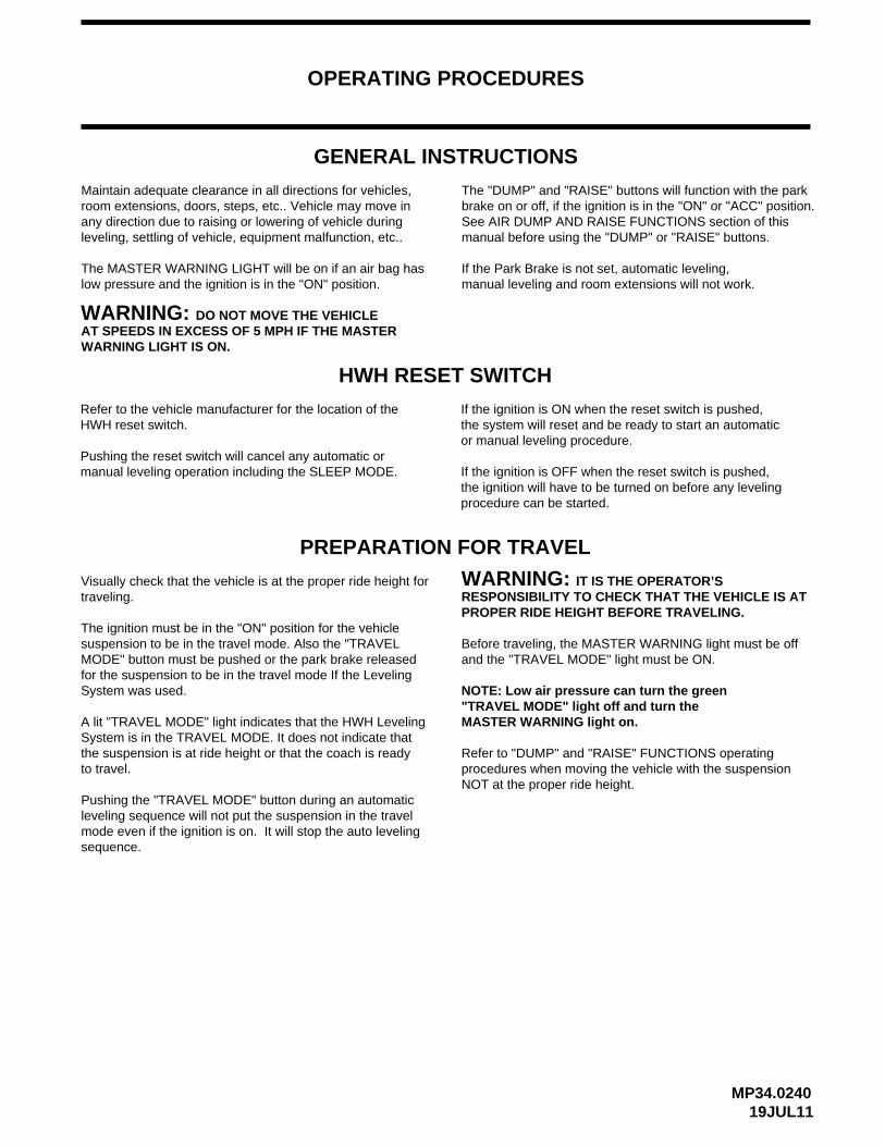
GENERAL INSTRUCTIONS
Maintain adequate clearance in all directions for vehicles,room extensions, doors, steps, etc.. Vehicle may move inany direction due to raising or lowering of vehicle during leveling, settling of vehicle, equipment malfunction, etc..
The MASTER WARNING LIGHT will be on if an air bag has low pressure and the ignition is in the "ON" position.
DO NOT MOVE THE VEHICLE
The "DUMP" and "RAISE" buttons will function with the parkbrake on or off, if the ignition is in the "ON" or "ACC" position.See AIR DUMP AND RAISE FUNCTIONS section of this manual before using the "DUMP" or "RAISE" buttons.
If the Park Brake is not set, automatic leveling, manual leveling and room extensions will not work.
HWH RESET SWITCH
Refer to the vehicle manufacturer for the location of theHWH reset switch.
Pushing the reset switch will cancel any automatic ormanual leveling operation including the SLEEP MODE.
If the ignition is ON when the reset switch is pushed,the system will reset and be ready to start an automatic or manual leveling procedure.
If the ignition is OFF when the reset switch is pushed,
AT SPEEDS IN EXCESS OF 5 MPH IF THE MASTER WARNING LIGHT IS ON.
PREPARATION FOR TRAVEL
Visually check that the vehicle is at the proper ride height for
The ignition must be in the "ON" position for the vehicle suspension to be in the travel mode. Also the "TRAVEL MODE" button must be pushed or the park brake released for the suspension to be in the travel mode If the Leveling System was used.
A lit "TRAVEL MODE" light indicates that the HWH LevelingSystem is in the TRAVEL MODE. It does not indicate that the suspension is at ride height or that the coach is ready to travel.
traveling.
procedures when moving the vehicle with the suspensionRefer to "DUMP" and "RAISE" FUNCTIONS operating
"TRAVEL MODE" light off and turn the
and the "TRAVEL MODE" light must be ON.Before traveling, the MASTER WARNING light must be off
PROPER RIDE HEIGHT BEFORE TRAVELING.RESPONSIBILITY TO CHECK THAT THE VEHICLE IS AT
IT IS THE OPERATOR’S
NOT at the proper ride height.
MASTER WARNING light on.
NOTE: Low air pressure can turn the green
WARNING:
Pushing the "TRAVEL MODE" button during an automaticleveling sequence will not put the suspension in the travelmode even if the ignition is on. It will stop the auto levelingsequence.
WARNING:
the ignition will have to be turned on before any levelingprocedure can be started.

OPERATING PROCEDURES
MP34.341029OCT15
AUTOMATIC AIR OPERATION
The four red WARNING lights on the panel will come on. This
The vehicle should not be moved when these lights are on.indicates that the height control valves have been locked out.
sequence. The LEVELING SYSTEM ACTIVE LIGHT will flash.2. Press the "AIR" button once to start the automatic leveling
"NOT IN PARK/BRAKE" light will be on while the "AIR" the panel will not turn on if the park brake is not set. The
required for leveling.will level with the engine shut off, however more time will beThis will provide a better air supply for leveling. The vehicleLeaving the engine running during leveling is recommended.turned on if the ignition is in the "ON" or "ACC" position.and set the park brake. The air leveling system can only be 1. Place the transmission in the proper position for parking
started, the ignition can be moved to the "OFF" position position to use the "AIR" button. Once the operation is
button is being pushed.
NOTE: If the ignition key is in the "ON" or "ACC" position,
NOTE: The ignition must be in the "ON" or "ACC"
3. SLEEP MODE: When all four yellow level lights are out,the LEVELING SYSTEM ACTIVE LIGHT will flash rapidly.The Leveling System is now in the SLEEP MODE. The
and the operation will continue.
NOTE: Only one or two yellow LEVEL SENSING lights may be ON at one time.
four red warning lights will go out. The vehicle’s engine/ignition
4. 30 minutes after the Leveling System enters the SLEEPMODE, the computer will monitor the LEVELING SENSINGUNIT for one minute. If no leveling is needed, the computerwill continue to monitor the LEVELING SENSING UNIT.
park brake is released, if the ignition is in the "ON" position.button or the "TRAVEL MODE" button is pushed or the6. The SLEEP MODE will continue until the "CANCEL"
the system is re-leveling the vehicle.NOTE: The four red warning lights will be on anytime
light will come on. The LEVELING SYSTEM ACTIVE lightif a LEVEL SENSING light is still on, the "EXCESS SLOPE"vehicle for approximately 30 minutes. After the 30 minutes,
The system will attempt to level the EXCESS SLOPE:The system will first exhaust all air from the suspension airbags regardless of the status of the yellow level lights. Afterapproximately 40 seconds, if no yellow light is on, the systemwill go directly to the sleep mode. If yellow lights are on,the system will add air to air bags to raise the low side orend of the vehicle, starting with any lit side yellow light.
may now be turned OFF. The blue SYSTEM ACTIVE
5. If the vehicle needs to be re-leveled, the Leveling System touch panel lights will come on and the leveling procedure will begin. The LEVELING SYSTEM ACTIVE LIGHT will flash. One or two yellow LEVELING LIGHTS will be ON. The system will re-level the vehicle. When the yellow LEVELING LIGHTS are all out, the LEVELING SYSTEM ACTIVE LIGHT will flash rapidly and return to the SLEEPMODE. The Leveling System will remain in the SLEEPMODE with the computer monitoring the LEVELINGSENSING UNIT, re-leveling the vehicle as needed.
will go out. The system will NOT be in the SLEEP MODE.The "EXCESS SLOPE" light will go out when the ignitionis turned off.
NOTE: If the system went EXCESS SLOPE during anautomatic leveling procedure, the "EXCESS SLOPE"light will be on any time the ignition is on until the "TRAVEL MODE" button is pushed or the park brake is released with the ignition on.
When the "EXCESS SLOPE" light is on, the "AIR" buttonwill not function. The manual UP or DOWN arrows and the"RAISE" or "DUMP" buttons will function if the ignition is on.
The system will re-level the vehicle. When the yellow
LIGHT will continue to flash rapidly.

OPERATING PROCEDURES
MP34.370528OCT15
MANUAL AIR OPERATION
NOTE: The RAISE and LOWER buttons will not function
NOTE: If the "DUMP" or "RAISE" buttons are pushed
if the system is in automatic leveling or the SLEEP mode.
before leveling the vehicle front to rear.
while manually leveling the vehicle with air and the ignition is in the "ON" position, the system will latch into the dump or raise mode until the "CANCEL"button is pushed or the ignition is turned off.
3. Turn the ignition to the "OFF" position.
4. Turn the system off.
"DUMP" AND "RAISE" FUNCTIONS
WARNING: REREAD CAUTIONS ON THE FIRST PAGE OF THIS MANUAL. THE VEHICLE MAY DROP OR RAISE AND/OR MOVE FORWARD OR BACKWARD WITHOUT WARNING CAUSING INJURY OR DEATH.
RESPONSIBILITY TO CHECK THAT THE VEHICLEIS AT PROPER RIDE HEIGHT BEFORE TRAVELING.
WARNING: IT IS THE OPERATOR’S
The "DUMP" and "RAISE" functions are provided for operator convenience for purposes such as dumping the air suspension when parked.
1. Place the transmission in the proper position for parking and set the park brake. The manual raise and lower buttons can only be used if the ignition is in the "ON" or "ACC"position. Running the vehicle engine during leveling is recommended. This will provide a better air supply for leveling. The vehicle will level with the engine shut off, however more time will be required for leveling.
2. The vehicle can be leveled using the RAISE (up arrow)and LOWER (down arrow) buttons on the right half of the panel in conjunction with the yellow LEVEL indicator lights. Any side to side leveling should be done, if needed,
DO NOT operate the vehicle for extended distances unless the air suspension is at the proper height for travel. The vehicle can not return to ride height until the "CANCEL" button or "TRAVEL MODE" button is pushed; or the vehicle exceeds 10 MPH, putting the system in the TRAVEL MODE if the park brake is
Push the "CANCEL" button with the ignition in the "ON"or "ACC" position to use the manual RAISE and LOWERbuttons.
low. When all yellow lights are out the vehicle is level.Try leveling the vehicle by lowering the high side or end
the low side or end.is not achieved use the RAISE (up arrow) button to raise(opposite of the lit yellow level lights). If a level position
The yellow LEVEL indicator light indicates that side or end is
The ignition must be in the "ON" or "ACC" positionto use the "DUMP" or "RAISE" buttons.
Leave the engine running if the "RAISE" function is to beused. The park brake DOES NOT have to be set to use the"DUMP" or "RAISE" buttons.
IMPORTANT: When the "RAISE" button is pushed, theraise feature will latch in and remain on. The vehiclewill raise to the maximum capability of the suspensionand stay in that position.
When the "DUMP" button is pushed, the dump featurewill latch in and stay on. The vehicle will lower until thesuspension air bags are completely empty and stay inthat position.
To stop a Dump or Raise function when thepark brake is set:
A. Push the "CANCEL" button or turn the ignition off.the vehicle will stop raising or lowering and stay inthat position.
Push the "TRAVEL MODE" button. The vehicle will stopB.raising or lowering and start to return to ride height.
To stop a DUMP or RAISE function if thepark brake is NOT set:
If the vehicle is moving and the speed exceedsA.approximately 10 MPH, the system will return to theTravel Mode. The vehicle should return to ride height.
Push the "TRAVEL MODE" button or the "CANCEL"B.button. The system will immediately return to the"TRAVEL MODE". The vehicle should return to rideheight.
C. Turn the ignition off. The vehicle will stop raising orlowering and stay in that position.
released.
DO NOT turn theignition off if the vehicle is moving.
If any manual button is pushed, the four red warninglights will come on and remain on any time the ignitionis in the ’ON’ or ’ACC’ position.

OPERATING PROCEDURES
ROOM EXTEND PROCEDURE
1. Unlock all room-locking devices.
the room remove it before extending the room.
WARNING:
extend the room.
2. To extend the room, press and hold the ROOM CONTROL SWITCH in the "EXTEND" position
halt the operation of the room.
KEEP PEOPLE AND OBSTRUCTIONSCLEAR OF ROOM WHEN OPERATING.
NOTE: If a MANUAL RETRACT WINCH is attached to
NOTE: Make sure there is adequate clearance to fully NOTE: Releasing the ROOM CONTROL SWITCH will
NOTE: The park brake must be set before a room can be extended or retracted.
after the room is fully extended or stops moving.in the "EXTEND" position for more than ten seconds
of the room, do not reverse direction of the room until
after the room is fully extended. This assures proper Hold the switch to "EXTEND" three or four seconds
pressurization of the cylinders.
Do not hold the ROOM CONTROL SWITCHIMPORTANT:
NOTE:
During normal operation
the room is fully extended. If necessary, the direction of the room may be reversed, but watch for binding of the room. If the direction of the room has been reversed, DO NOT re-extend the room until the room has been fully retracted.
If either side of the room stops moving, release the room control switch immediately. DO NOT force the room. DO NOT reverse direction of the room, contact HWH Customer Service for assistance 1-800-321-3494.
until the room is fully extended.
MP34.434519JUL11
DISENGAGED BEFORE OPERATING THE ROOM.RETRACTING DEVICES ARE DETACHED ORALL ROOM LOCKING, CLAMPING OR MANUALOPERATOR’S RESPONSIBILITY TO ENSURE THATPERSONAL INJURY AND VEHICLE DAMAGE. IT IS THEDEVICES ATTACHED OR ENGAGED CAN CAUSEROOM LOCKING, CLAMPING OR MANUAL RETRACTING WARNING: OPERATING A ROOM WITH ANY
It is recommended to complete the Leveling Procedurebefore operating room extensions.
IMPORTANT: DO NOT USE A ROOM EXTENSIONSUPPORT WHEN THE VEHICLE IS SUPPORTED BYTHE LEVELING SYSTEM.

OPERATING PROCEDURES
ROOM RETRACT PROCEDURE
1. To retract the room press and hold the ROOM CONTROL SWITCH in the "RETRACT"
halt the operation of the room.
2. Engage all room-locking devices.
IMPORTANT: Room-locking devices should be locked while traveling.
WARNING:CLEAR OF ROOM WHEN OPERATING.
KEEP PEOPLE AND OBSTRUCTIONS
3. If the room will not retract see the MANUAL ROOM RETRACT PROCEDURE.
NOTE:
NOTE:NOTE: Releasing the ROOM CONTROL SWITCH will
The park brake must be set before a room can beextended or retracted.
HWH Customer Service for assistance 1-800-321-3494.room. DO NOT reverse direction of the room, contact room control switch immediately. DO NOT force the If either side of the room stops moving, release the after the room is fully retracted or stops moving.in the "RETRACT" position for more than ten seconds
Do not hold the ROOM CONTROL SWITCH
reversed, DO NOT retract the room until the room the room. If the direction of the room has been of the room may be reversed, but watch for binding of the room is fully retracted. If necessary, the direction of the room, do not reverse direction of the room until
During normal operation
Hold the switch to "RETRACT" three or four secondsafter the room is fully retracted. This assures proper
has been fully extended.
pressurization of the cylinders.
IMPORTANT:
NOTE:
position until the room is fully retracted.
MP34.454519JUL11
It is recommended to retract the rooms before puttingthe leveling system in the TRAVEL MODE.

"UNIVERSAL STRAIGHT OUT" ROOM EXTENSION MECHANISM
MANUAL ROOM RETRACTION PROCEDURES
MP34.957708FEB10
OPERATING PROCEDURES
PLATERECEIVER
RODTHREADED
ROOM EXTENDED
THREADEDBLOCK
ROOM RETRACTED
BLOCKTHREADED
THREADEDROD
manufacturer.
the front and one for the rear mechanism should be provided.2. Start both threaded rods until resistance is met, one for
IMPORTANT: ONLY MOVE THE RELEASE CAM
NOTE: To access the threaded blocks refer to vehicle
See the HYDRAULIC PUMP/ MANIFOLD diagram.the valve release cams to the open position. assigned to the room. Manually open both valves by moving1. Determine which extend and retract solenoid valves are 4. Move to the other room extension mechanism, rotate
the room, contact HWH Customer Service for assistance understood or if the room begins to bind DO NOT force IMPORTANT: If at any stage something is not
6. Repeat steps 4 and 5 alternating from mechanism to mechanism rotating each threaded rod 12 completeturns until room is sealed. (DO NOT exceed 15
5. Return to the first room extension mechanism and rotate the threaded rod clockwise 12 complete turns.
the threaded rod clockwise 12 complete turns.
ft.lbs) Make sure the room does not bind.
1-800-321-3494.
Do Not use an impact wrench.
either mechanism’s threaded rod clockwise 6 complete turns.a personal wrench or a tire iron with a 1-1/8" opening rotate 3. Using wrench provided,
threaded rods impact the coach wall or the mechanism.Be careful to not extend the room so far that the threaded rods out and slightly extending the room. threaded rods completely, alternate backing the NOTE: If there is not enough room to remove both
ROOM HAS BEEN SERVICED. ANY SOLENOID VALVES
RODS SHOULD BE COMPLETELY REMOVED.LEFT OPEN SHOULD BE CLOSED AND THE THREADED
IMPORTANT: DO NOT EXTEND THE ROOM UNTIL THE
threaded rods in place until the room has beenNOTE: Leave the solenoid valves open and the
serviced.
IN THE DIRECTION SHOWN. MOVING THE CAMIN THE OPPOSITE DIRECTION CAN DAMAGETHE VALVES.
HYDRAULIC PUMP/MANIFOLD
SOLENOID VALVESVALVE RELEASE CAMS
(VALVE CLOSED)
BREATHERCAP-DIP
(VALVE OPEN)
STICK
MAINTENANCE
MP44.002519JUL11
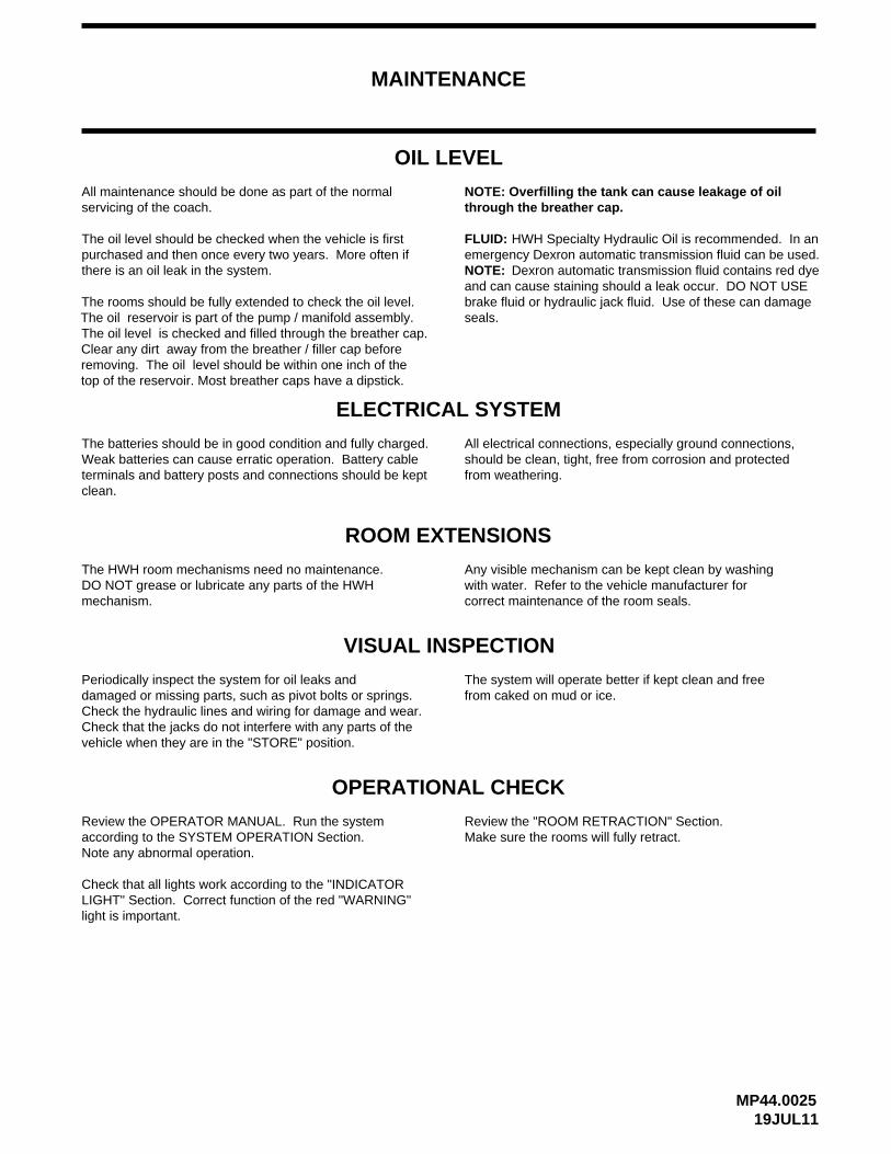
OIL LEVEL
The oil level should be checked when the vehicle is first purchased and then once every two years. More often if there is an oil leak in the system.
NOTE: Overfilling the tank can cause leakage of oil through the breather cap.
ELECTRICAL SYSTEM
The batteries should be in good condition and fully charged.Weak batteries can cause erratic operation. Battery cable terminals and battery posts and connections should be kept
All electrical connections, especially ground connections, should be clean, tight, free from corrosion and protected
VISUAL INSPECTION
Periodically inspect the system for oil leaks and damaged or missing parts, such as pivot bolts or springs.Check the hydraulic lines and wiring for damage and wear. Check that the jacks do not interfere with any parts of the vehicle when they are in the "STORE" position.
The system will operate better if kept clean and free from caked on mud or ice.
OPERATIONAL CHECK
Check that all lights work according to the "INDICATOR LIGHT" Section. Correct function of the red "WARNING"
Review the OPERATOR MANUAL. Run the system according to the SYSTEM OPERATION Section. Note any abnormal operation.
Review the "ROOM RETRACTION" Section. Make sure the rooms will fully retract.
All maintenance should be done as part of the normal servicing of the coach.
clean.from weathering.
light is important.
FLUID: HWH Specialty Hydraulic Oil is recommended. In an
brake fluid or hydraulic jack fluid. Use of these can damage and can cause staining should a leak occur. DO NOT USE
Dexron automatic transmission fluid contains red dyeemergency Dexron automatic transmission fluid can be used.
seals.
NOTE:
ROOM EXTENSIONS
The HWH room mechanisms need no maintenance.DO NOT grease or lubricate any parts of the HWHmechanism.
Any visible mechanism can be kept clean by washingwith water. Refer to the vehicle manufacturer forcorrect maintenance of the room seals.
The rooms should be fully extended to check the oil level. The oil reservoir is part of the pump / manifold assembly. The oil level is checked and filled through the breather cap. Clear any dirt away from the breather / filler cap before removing. The oil level should be within one inch of thetop of the reservoir. Most breather caps have a dipstick.

MAINTENANCE
NOT IN PARK/BRAKE CHECK
THE COACH WHEELS SECURELY SO THE COACH CANNOT ROLL FORWARD OR BACKWARD.
WARNING: WHEN MAKING THIS CHECK, BLOCK If any of the above checks or inspections reveal a problem or if there are other problems or questions, consult a qualified RV repair center, your vehicle or coach manufacturer, or HWH CORPORATION
22NOV16MP44.0515
for service or repair.Switch the ignition to the "ON" or "ACC" position. Release the park brake. Push and hold the "AIR" button.The "NOT IN PARK/BRAKE" light should come on whilepushing the "AIR" button. The system should not function.Release the "AIR" button and set the park brake. Pushthe "AIR" button. The system should start to level.
WINTER WEATHER DRIVING
components, such as HWH jacks.have dried. This can facilitate corrosion of metallic
Anti-icing / deicing agents when splashed on your vehicle,continue to absorb moisture from the air even after they icing / deicing agents, thoroughly wash jacks with warm
To help reduce the corrosion of jacks after exposure to anti-
soapy water.

SENSING UNIT MAINTENANCE/SERVICE
SENSING UNIT ADJUSTMENT / WITH ADJUSTING ENHANCEMENT
NOTE: If opposing LED’s are lit, there is a problem withthe Sensing Unit.
If LED (A) is lit: Tighten adjustment screw number 1until the LED is off.
If LED (C) is lit: Loosen adjustment screw number 1until the LED is off.
If LED (B) is lit: Loosen adjustment screw number 3until the LED is off.
until the LED is off.If LED (D) is lit: Tighten adjustment screw number 3
09NOV10MP44.1511
With the vehicle level according to the bubble level, if there are no yellow lights lit on the Touch Panel, the sensing unit is properly adjusted. If there are yellow LEVEL lights lit on the Touch Panel, manual adjustments to the Sensing Unit are needed.
SENSING UNIT ACCURACY TOLERANCE
The sensing unit has an accuracy tolerance of ± 5.4 inches front to rear and
INSTRUCTION SHEET
± 1 inch side to side on a 36 foot vehicle. Typical leveling results will be better.
IMPORTANT: THE SENSING UNIT MOUNTING SPRINGSSHOULD BE COMPRESSED ABOUT 1/2 THEIR FREELENGTH. SCREW NUMBER 2 SHOULD NOT BE TURNED
MOUNTED BELOW
FRONT
MOUNTING SURFACE
(3) MOUNTING
(3) MOUNTING
SCREWS
SPRINGS
THISSIDEUP
LED A - FRONT OF VEHICLELED B - LEFT SIDE OF VEHICLELED C - REAR OF VEHICLELED D - RIGHT SIDE OF VEHICLE
REMOTE MOUNTED "POTTED" ELECTRONIC SENSING UNIT
WHILE ADJUSTING THE SENSING UNIT. AFTERADJUSTING THE SENSING UNIT, BUMP THE SENSINGUNIT TO SEE THAT IT IS SETTLED TIGHT AGAINST ALLTHREE SCREW HEADS AND STILL INDICATES THATTHE UNIT IS LEVEL.
Level the vehicle by placing a bubble level in the center of the freezer floor or upon whichever surface within the vehicle that is to be level. It is best if the level is placed close to the mounting area of the sensing unit. Using the Leveling System and the bubble level, ignoring the yellow LEVEL lights on the Touch Panel, level the vehicle until the bubble is centered.
The ignition (motorized units) or master power switch (towableunits) must be on. Remove the "Adjusting Enhancement Cap".DO NOT LOSE THIS CAP. There is a small pin beneath thecap. Use a jumper wire with an alligator clip to apply a groundto the pin. This will make the sensing unit very sensitive. Theyellow lights may "jump" around while adjusting the sensing unit.Let the lights settle down after each adjustment. Small, gentleturns will work best. Turn mounting screws 1 and 3 to adjustthe sensing unit. Turn screws as instructed to turn out all theyellow LEDs. When all the LEDs are out, remove the jumperwire and replace the adjusting enhancement cap. DO NOTover tighten.
SENSING UNITBOTTOM VIEW OF
LED
3
D
CLED
LEDA
BYELLOW LEDs
2
MOUNTING/ADJUSTMENTSCREWS (3)
1
LED
Move the vehicle to an unlevel position and level thevehicle according to the yellow level sensing lights onthe touch panel. Readjust if necessary.
ADJUSTINGENHANCEMENTCAP

MP44.350004JUN18
TIFFIN MOTOR HOMES WITH SINGLE STEP AIR LEVELING
FRONT AIR MANIFOLD PRESSURE REGULATOR ADJUSTMENT
DO NOT CRAWL UNDER THE VEHICLE WHEN SUPPORTED WITH THE SUSPENSION AIR BAGS.PROPERLY SUPPORT THE VEHICLE FRAME BEFORE CRAWLING UNDER THE VEHICLE TO ADJUST THE FRONTWARNING:
MANIFOLD AIR REGULATOR OR TO PERFORM OTHER WORK.
NOTE: It is best if the vehicle is on a flat level surface when adjusting the regulator.
1. Remove the 1/8 inch pipe plug from the regulator. It is recommended to drain the air from the air tanks before removing the plug. Removing the plug will exhaust the air from the air tanks. Install the pressure gauge assembly onto the regulator.
IMPORTANT: MAKE SURE THE AIR TANKS ARE AT FULL PRESSURE BEFORE ADJUSTING THE REGULATOR.YOU SHOULD HEAR THE AIR DRYER PURGE VALVE RELEASE WHEN THE AIR TANKS ARE FULL.
WH
HCO
RP
OR
AT
ION
R
12. After the regulator is adjusted, refer to Manual ML46839, Performance Check List for 2000 series Single Step Air Leveling System to fully test the system.
11. Remove the pressure gauge assembly from the regulator and re-install the 1/8 inch plug. Use Teflon tape to seal the threads. Be careful to not get Teflon tape inside the regulator.
10. Leave the regulator pressure at the final setting and push the adjustment knob in to lock the regulator setting.
9. Repeat this procedure, increasing the regulator pressure by 5 psi each time until the front of the vehicle does not raise at all when the UP ARROW button is pushed.
7. Adjust the regulator up 5 psi from 50 psi. to 55 psi. Remember to support the vehicle before crawling under the
8. Again, push and hold the front UP ARROW button until the front of the vehicle stops rising. Measure at the trim line again and record the measurement.
6. Measure from the ground to the trim line of the vehicle at the approximate center of both front wheel wells. Use a piece of tape to mark the measuring points. It is important to measure at the same place each time. Record the measurements.
5. Push and hold the HWH touch panel front UP ARROW button until the front of the vehicle stops rising. Check to make sure both front air bags are filling with air.
4. Push and hold the HWH touch panel front DOWN ARROW button until the front air bags are empty. Check the air bags. Repeat this with the rear DOWN ARROW button. Again, check the air bags.
3. Turn the regulator adjustment knob counterclockwise until the gauge reads 0 psi. Turn the knob clockwise until the gauge reads 50 psi. It is important to turn the regulator down, then back up to properly adjust the regulator.
2. To unlock the adjusting knob of the front air manifold regulator, pull the knob out, away from the main bodyof the regulator.
PRESSURE GAUGE
50
100
150
200
AXLE AIR IN
[ HCV ]
BY-PASS
VALVEBAG
BY-PASS
VALVE
EXHAUST
BAG
PSW
L
E
F
T
R
I
G
H
TBAG
AIR
IN
ASSEMBLY
1/8 INCHPLUG
REGULATOR
KNOBADJUSTMENT
UNLOCK
LOCK
DO NOT use Teflon tape or pipe sealant on the gauge assembly threads. DO NOT over tighten the gauge assembly. Seethe diagram below. Save the 1/8 inch plug so it can be reinstalled after adjustment of the regulator is complete.
vehicle.

MP64.512019JUL11
MULTIPLE EXTENSIONSHYDRAULIC LINE CONNECTION DIAGRAM
VALVE FUNCTION
2R - ROOM CYLINDER RETRACT - ROOM EXTEND
2E - ROOM CYLINDER EXTEND - ROOM RETRACT
ROOM MECHANISMUNIVERSAL STRAIGHT OUTCONNECTION DIAGRAMSEE HYDRAULIC LINE
EXTEND ROOM TO ROOM 1 (DRIVER SIDE FRONT)
CHECK OIL LEVEL
ROOM 2 (PASSENGER SIDE FRONT)
CHECK OIL LEVELEXTEND ROOM TO
IMPORTANT: DO NOT SWAP CAP OR RODHOSES BETWEEN ROOMS OR DAMAGETO EQUIPMENT MAY RESULT.
SOLENOIDVALVES
RETRACT
CONNECTION - BROOM CYLINDERS
CAP END
ROOM CYLINDERSCONNECTION - AROD END
VALVESSOLENOIDEXTEND
ROOM CYLINDERSCONNECTION - BCAP END
ROOM CYLINDERSCONNECTION - AROD END
1E - ROOM CYLINDER EXTEND - ROOM RETRACT
1R - ROOM CYLINDER RETRACT - ROOM EXTEND
R1
R2
E1
E2
CONNECTION DIAGRAMSEE HYDRAULIC LINE
UNIVERSAL STRAIGHT OUTROOM MECHANISM
MP64.8300B27JUL11
E F
ROD ENDROD END
CAP END END
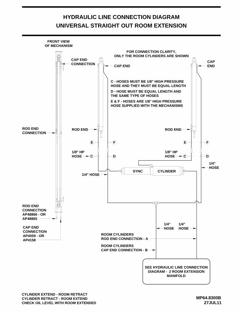
FOR CONNECTION CLARITY,ONLY THE ROOM CYLINDERS ARE SHOWN
E F
SYNC CYLINDER
ROOM CYLINDERSROD END CONNECTION - A
ROOM CYLINDERSCAP END CONNECTION - B
CYLINDER EXTEND - ROOM RETRACTCYLINDER RETRACT - ROOM EXTENDCHECK OIL LEVEL WITH ROOM EXTENDED
CONNECTIONCAP END
ROD ENDCONNECTION
FRONT VIEWOF MECHANISM
CAP
C D C DHOSE1/8" HP
HOSE1/8" HP
1/4"HOSE
THE SAME TYPE OF HOSESD - HOSE MUST BE EQUAL LENGTH AND
HOSE AND THEY MUST BE EQUAL LENGTHC - HOSES MUST BE 1/8" HIGH PRESSURE
HOSE SUPPLIED WITH THE MECHANISMSE & F - HOSES ARE 1/8" HIGH PRESSURE
HOSE1/4" 1/4"
HOSE
1/4" HOSE
UNIVERSAL STRAIGHT OUT ROOM EXTENSION
HYDRAULIC LINE CONNECTION DIAGRAM
SEE HYDRAULIC LINE CONNECTIONDIAGRAM - 2 ROOM EXTENSION
MANIFOLD
AP4158
AP48865
ROD ENDCONNECTIONAP48866 - OR
AP4059 - ORCONNECTIONCAP END

4 - POINT AIR LEVELING SYSTEM
MP74.001021APR10
FR
ON
T
CONNECTION
TO SUSPENSION
FRONT
AIR BAG
AIR LINE CONNECTION DIAGRAM
DIAGRAM - HWHAIR COMPRESSOR
SEE AIR LINE
HCV
HCV
CV
HCV
H
PRESSUREPROTECTION
MANIFOLD
TO VEHICLE AIR SUPPLY
SEE FRONT AND REAR AIR SOLENOID MANIFOLDCONNECTION DIAGRAMS FOR SPECIFIC VALVEAND AIR MANIFOLD CONNECTION INFORMATION
HEIGHTCONTROLVALVE (4)
AIRSUPPLY
MANIFOLDREAR LINES FROM HEIGHT
CONTROL VALVES
LINES TO AIR BAGS
HEIGHT CONTROLLINES FROM
MANIFOLD
AIR BAGS
VALVES
LINES TO

AIRBAG
AIRBAG
MANIFOLD ASSEMBLY
EXHEXH
HCVHCV
4-POINT LEVELING SYSTEM SCHEMATICPRESSURE SWITCHES FRONT AND REAR
MP74.265013APR10
RAISE
LOWER
TRAV.
RAISE
LOWER
TRAV.
EXH EXH
AIR LINE CONNECTION DIAGRAM
MANIFOLD ASSEMBLY
SEE AIR LINE CONNECTIONDIAGRAM - HWH AIR
COMPRESSOR SCHEMATIC
EXH
HCV
EXH
HCV
LOWER
TRAV.
LOWER
RAISE
AIRBAG
EXH
RAISE
TRAV.
EXH
AIRBAG
NORMALLY CLOSEDPRESSURE SWITCH
PRESSUREPROTECTION
MANIFOLD
TO VEHICLEAIR SUPPLY
85 PSI
PRESSURECLOSEDNORMALLY
SWITCH 20 PSI

MP74.2670A05SEP14
AIR SOLENOID MANIFOLD6 VALVE WITH TWO PRESSURE SWITCHES
AND BY-PASS VALVES
WH
HCO
RP
OR
AT
ION
R
CHECK VALVES
AIR SUPPLY
AIR BAGSLINE TO
CONTROLHEIGHTLINE FROM
VALVES
3.400"
FRONT AIR MANIFOLD
RIGHT SIDE VIEW
LEFT AND RIGHT
MOUNTING HOLES
LINE FROM HEIGHTCONTROL VALVE (MAY BETEED TOGETHER IF ONE
EXHAUST PORTS(2 LEFT AND RIGHT)
PRESSURE SWITCH20 PSI (2 LEFT AND RIGHT)
LINE TO AIR BAGS(2 LEFT AND RIGHT)
BE INTERCHANGED.AIR SOLENOID VALVES CANNOT FOR AIR PRESSURE SWITCHES ANDAS SHOWN. GROUND SUPPLY WIRESCONNECTIONS MUST BE MAINTAINED
PRESSUREREGULATOR
AIR SUPPLY
HCV IS USED)
IMPORTANT:
SOLENOID VALVE (LEFT
VALVE NOT SHOWN)
VALVE NOT SHOWN)
RIGHT RAISE
VALVE (2)CHECK
RIGHT TRAVELSOLENOID VALVE (LEFTVALVE NOT SHOWN)
RIGHT LOWERSOLENOID VALVE (LEFT
AAB B A B A B
PS
WR
S
B A B A B BA
AB B A AB B A B A AB B BA A
A
REAR VIEW
SWITCHES (2)PRESSURE
PRESSURE REGULATOR
RA
ISE
RS
LOW
ER
RS
RS
TR
AV
EL
LST
RA
VE
L
LOW
ER
LS
RA
ISE
LS
PS
WLS
TR
AV
EL
RS
LOW
ER
RS
PS
WLS
RA
ISE
LS LSLO
WE
R
TR
AV
EL
LS
RA
ISE
LS
PS
WLS
TO HARNESSCONNECTOR
I/O MODULE CONNECTIONS
NOTE: I/O MODULE NOT SHOWNSEE ELECTRICAL CONNECTION DIAGRAM
FRONT AIR I/O MODULE - PAGE 2 OF 2
(REGULATOR WILL NOT BE PRESENTON 2014 MODEL COACHES OR NEWER)

MP74.2680A25JUL11
AIR SOLENOID MANIFOLD6 VALVE WITH THREE PRESSURE SWITCHES
AND BY-PASS VALVES
WH
HCO
RP
OR
AT
ION
R
CHECK VALVES
AIR SUPPLY
AIR BAGSLINE TO
CONTROLHEIGHTLINE FROM
VALVES
3.400"
REAR AIR MANIFOLD
PRESSURE SWITCH
RIGHT SIDE VIEW
LEFT AND RIGHT
MOUNTING HOLES
LINE FROM HEIGHTCONTROL VALVE (MAY BETEED TOGETHER IF ONE
EXHAUST PORTS(2 LEFT AND RIGHT)
PRESSURE SWITCH20 PSI (2 LEFT AND RIGHT)
LINE TO AIR BAGS(2 LEFT AND RIGHT)
BE INTERCHANGED.AIR SOLENOID VALVES CANNOT FOR AIR PRESSURE SWITCHES ANDAS SHOWN. GROUND SUPPLY WIRESCONNECTIONS MUST BE MAINTAINED
PRESSURESWITCH-85 PSI
AIR SUPPLY
HCV IS USED)
IMPORTANT:
SOLENOID VALVE (LEFT
VALVE NOT SHOWN)
VALVE NOT SHOWN)
RIGHT RAISE
VALVE (2)CHECK
RIGHT TRAVELSOLENOID VALVE (LEFTVALVE NOT SHOWN)
RIGHT LOWERSOLENOID VALVE (LEFT
AAB B A B A B B A B A B BA
AB B A AB B A B A AB B BA A AB
A AB
REAR VIEW
SWITCHES (2)PRESSURE
REAR AIR I/O MODULE - PAGE 2 OF 2SEE ELECTRICAL CONNECTION DIAGRAM
I/O MODULE CONNECTIONS
CONNECTORTO HARNESS
TR
AV
EL
RS
LOW
ER
RA
ISE
RS
LS LSP
SW
NOTE: I/O MODULE NOT SHOWN
TR
AV
EL
RS
LOW
ER
RA
ISE
RS
RS
RS
PS
W
PS
WLS LS
RA
ISE
LSLO
WE
R
TR
AV
EL
LS
SY
SP
SW
PS
WS
YS
LSP
SW
LSR
AIS
E
LOW
ER
LS LST
RA
VE
L

AIR LINE CONNECTION DIAGRAM
12 VOLT RELAY AIR FILTER
13APR10MP74.4622
BATTERY
GROUND
FROM +12
FLOW
RELIEF VALVE(110 PSI)
AIR SOLENOID
TO HWH AIR
+12 CONTROL
COMPRESSORFROM HWH AIR
LEVELING MANIFOLDS
NORMALLY OPEN
HWH AIR COMPRESSOR
HARNESS
15 AMPFUSE
VALVECHECK
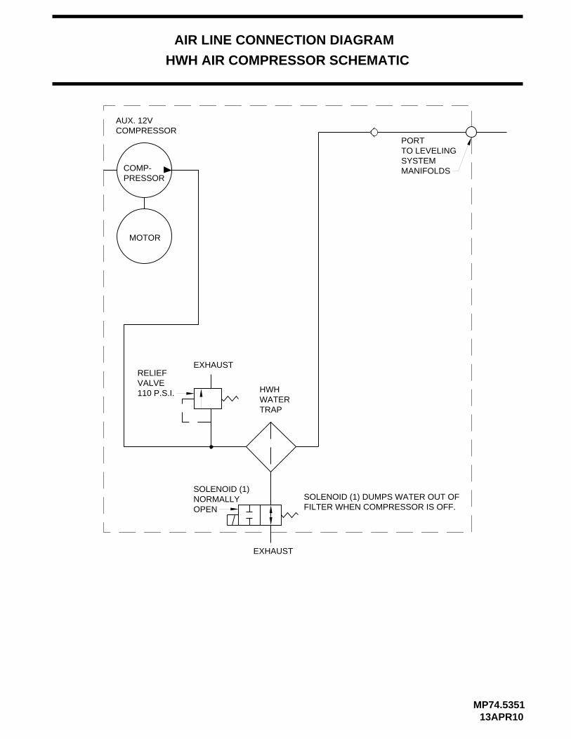
AIR LINE CONNECTION DIAGRAM
HWH AIR COMPRESSOR SCHEMATIC
COMP-PRESSOR
MOTOR
EXHAUST
EXHAUST
SOLENOID (1)NORMALLYOPEN
RELIEFVALVE110 P.S.I.
AUX. 12VCOMPRESSOR
SOLENOID (1) DUMPS WATER OUT OFFILTER WHEN COMPRESSOR IS OFF.
PORTTO LEVELINGSYSTEMMANIFOLDS
HWHWATERTRAP
13APR10MP74.5351

700 SERIES AIR LEVELING
MP84.306027JUL11
ELECTRICAL CONNECTION DIAGRAM
HARNESS ROUTING
AB
FRONT AIR MANIFOLDI/O MODULE
SEE MP84.3180
62357500 9700
AIR COMPRESSORCONNECTIONSSEE MP84.6085
SYSTEM LATCHIN RELAYS
SEE MP84.3200
AB
61206101
SEE MP84.3190I/O MODULE
REAR AIR MANIFOLD
FUSE15 AMP
6100
6120ACC
6101
62321210
B A
6232
B A
2210
LEFT FRONTPRESSURE
SWITCHPRESSURE
RIGHT FRONT
SWITCH
LEVEL SENSING UNITSEE MP84.3433
SWITCH
RIGHT REARPRESSURE
6233
B
LEFT REARPRESSURE
SWITCH
3210
A
SYSTEMPRESSURE
SWITCH
A B BA
6233 623332154210
PUMP/POWER RELAYCONNECTIONS - SEE MP84.3290
6230
6100
HWH COMPUTERIZED LEVELING
WARNING!UNDERSTAND OPERATOR’S MANUAL BEFORE USING. BLOCK FRAME AND TIRES
SECURELY BEFORE REMOVING TIRES OR CRAWLING UNDER VEHICLE.
CANCEL
MODETRAVEL
LEVEL
MODETRAVEL
RAISE
BRAKEPARK/
SLOPEEXCESS
NOT IN
DUMP
AIR
TOUCH PANELSEE MP84.6195
TO +12 BATTERY
GR
OU
ND
PA
RK
BR
AK
E
SP
EE
D S
W
MASTERWARNING
LIGHT7699
6110
6230
9000
9900
LATCHSYSTEM
SEE MP84.3181
TRUNKHARNESS
HWH MAIN
HWH MAIN
HARNESSTRUNK
RE
SIS
TO
RT
ER
MIN
AT
ING
DO
NO
T C
UT
TE
RM
INA
TIN
GR
ES
IST
OR
DO
NO
T C
UT
RESETSWITCH
6101
6100
SEE MP84.3191

MP84.3180
ELECTRICAL CONNECTION DIAGRAM
700 SERIES FRONT AIR MANIFOLD MULTIPLEXED I/O MODULE
04JUN18
PIN # WIRECOLOR
WIRE NUMBER
WIRE DESCRIPTION AND FUNCTION
A1
WIRE CONNECTION INFORMATION - PAGE 1 OF 2
CAN HIGH COMMUNICATION WIREYELLOWA2 N/ANO CONNECTIONA3 THRU A5SW GND FROM RIGHT FRONT AIR PRESS. SWITCH - LOW PRESSURE2210BLACKA6NO CONNECTIONA7 AND A8+12 VOLT POWER TO THE TOUCH PANELREDB1 6122CAN LOW COMMUNICATION WIREGREEN N/AB2
B3 THRU B8 NO CONNECTION+12 VOLT POWER FOR LEVEL SENSING UNITC1 RED 6121SHIELD WIRE FOR GREEN & YELLOW CAN COMMUNICATION WIRESN/AC2 N/AGROUND FOR LEVEL SENSING UNITWHITEC3 6231SWITCHED GROUND FROM LEVEL SENSING UNIT - REAR LOW0400BLACKC4NO CONNECTIONC5
D1 RED 6102 SWITCHED +12 BATTERY FROM LATCH IN RELAYSGROUND FOR AIR MANIFOLD PRESSURE SWITCHESWHITED2 6232SYSTEM GROUND FOR I/O MODULES AND TOUCH PANELD3NO CONNECTIOND4SW GND FROM LEFT FRONT AIR PRESS. SWITCH - LOW PRESSUREBLACKD5 1200SWITCHED GROUND FROM LEVEL SENSING UNIT - LEFT SIDE LOW0100BLACKD6SWITCHED GROUND FROM LEVEL SENSING UNIT - FRONT LOWBLACKD7 0200SWITCHED GROUND FROM PARK BRAKE SWITCH - PARK BRAKE ONBLACKD8 9000
RIGHT FRONT TRAVELRIGHT FRONT LOWERRIGHT FRONT RAISEAIR COMPRESSOR
LINK LIGHT
FRONT VIEWOF I/OMODULECONNECTOR
A LIT RED LED INDICATES THERE SHOULD BE+12 VOLTS ON THE CORRESPONDING WIRE.
LINK LIGHT: LINK LIGHT FLASHING INDICATES PROPERCOMMUNICATION BETWEEN THE I/O MODULE AND THETOUCH PANEL. LINK LIGHT ON SOLID OR OFF INDICATESA FAILURE.
8 7 6 5 4 3 2 1ABCD
LEFT FRONT LOWERLEFT FRONT TRAVEL
SYSTEM LATCH
RED 6120 SWITCHED +12 ACC FROM IGNITION SWITCH
C6C7C8
BLACK 9900NO CONNECTION
BLACK 0300
+12 FROM SPEED SWITCH - LOW SPEED
SWITCHED GROUND FROM LEVEL SENSING UNIT - RIGHT SIDE LOW
WHITE 6230
EARLY MODULES MAYNOT HAVE LATCH LED*
* LEFTFRONTRAISE
*
* 6230 GROUND WIRE IS NOT PRESENT ON NEWER SYSTEMS.
*
*

MP84.3181
ELECTRICAL CONNECTION DIAGRAM
700 SERIES FRONT AIR MANIFOLD MULTIPLEXED I/O MODULE
04JUN18
WIRE CONNECTION INFORMATION - PAGE 2 OF 2
CONTROLW9700
RELAY COMP
W2700TRAVEL
RAISEW2500
W2600LOWER
RS
RS
RS
W7500RELAYLATCH
AIR
IN
BAG
E
F
T
L
PSW
BAG
EXHAUST
CO
RP
OR
AT
ION
HR
WH
T
H
G
R
I
VALVE
BY-PASS
[ HCV ]
BAG
AXLE AIR IN
VALVE
BY-PASS
BA
AB
AB
BA
BA
AB
AB
TRAVELW1700
LS
W1600LOWER
LS
LSRAISEW1500
BABA
SEE MP84.6085
SEE MP84.3200
SEE MP84.3290RED (6100)
WHITE (6230)
SEE MP84.3180INFORMATION
FOR CONNECTION
LEFT FRONTPRESSURE
SWITCH
RIGHT FRONTPRESSURE
SWITCH
6232
6232
1210
2210
1210
2210
6232
RED (6100)
WHITE (6234)
RED (6100)
WHITE (6234) 6235750061026120
62452700
62432600
62442500
17006246
16006241
15006242
TO HWH TOUCH PANEL
TO REAR I/O MODULE
HWH MAIN TRUNKHARNESS
SEE MP843433SENSING UNIT
WHITE
BLACK
HIGH CURRENTCONNECTOR
MAINCONNECTOR

MP84.3190
ELECTRICAL CONNECTION DIAGRAM
700 SERIES REAR AIR MANIFOLD MULTIPLEXED I/O MODULE
25JUL11
PIN # WIRECOLOR
WIRE NUMBER
WIRE DESCRIPTION AND FUNCTION
A1
WIRE CONNECTION INFORMATION - PAGE 1 OF 2
CAN HIGH COMMUNICATION WIREYELLOWA2 N/ANO CONNECTIONA3 THRU A5SW GND FROM RIGHT REAR AIR PRESS. SWITCH - LOW PRESSURE3210BLACKA6NO CONNECTIONA7 AND A8NO CONNECTIONB1CAN LOW COMMUNICATION WIREGREEN N/AB2
B3 THRU B7 NO CONNECTION
NO CONNECTIONC1SHIELD WIRE FOR GREEN & YELLOW CAN COMMUNICATION WIRESN/AC2 N/A
D1 RED 6122 +12 POWER FOR I/O MODULEGROUND FOR AIR MANIFOLD PRESSURE SWITCHESWHITED2 6233SYSTEM GROUND FOR I/O MODULED3NO CONNECTIOND4SW GND FROM LEFT REAR AIR PRESS. SWITCH - LOW PRESSUREBLACKD5 4210
RIGHT REAR TRAVELRIGHT REAR LOWERRIGHT REAR RAISE
LINK LIGHT
FRONT VIEWOF I/OMODULECONNECTOR
A LIT RED LED INDICATES THERE SHOULD BE+12 VOLTS ON THE CORRESPONDING WIRE.
LINK LIGHT: LINK LIGHT FLASHING INDICATES PROPERCOMMUNICATION BETWEEN THE I/O MODULE AND THETOUCH PANEL. LINK LIGHT ON SOLID OR OFF INDICATESA FAILURE.
8 7 6 5 4 3 2 1ABCD
LEFT REAR LOWERLEFT REAR TRAVEL
LEFT REAR RAISE
NO CONNECTION
WHITE 6230
BLACKB8 3215 SW GND FROM SYSTEM PRESSURE SWITCH - LOW PRESSURE
NO CONNECTIONC3 THRU C8
NO CONNECTIOND6 THRU D8

MP84.3191
ELECTRICAL CONNECTION DIAGRAM
700 SERIES REAR AIR MANIFOLD MULTIPLEXED I/O MODULE
04JUN18
WIRE CONNECTION INFORMATION - PAGE 2 OF 2
W3700TRAVEL
RAISEW3500
W3600LOWER
RS
RS
RS
E
F
T
L
PSW
BAG
EXHAUST
CO
RP
OR
AT
ION
HR
WH
T
H
G
R
I
VALVE
BY-PASS
[ HCV ]
BAG
AXLE AIR IN
VALVE
BY-PASS
BA
AB
AB
BA
AB
AB
TRAVELW4700
LS
W4600LOWER
LS
LSRAISEW4500
BABA
WHITE
BLACK
SEE MP84.3190INFORMATION
FOR CONNECTION
LEFT REARPRESSURE
SWITCH
RIGHT REARPRESSURE
SWITCH
6233
6233
4210
3210
4210
3210
3215
WHITE (6234)
RED (6100)
AB AIR
BAG
6233
3215
6233
62453700
62433600
62443500
TO FRONT I/O MODULE
HWH MAIN TRUNKHARNESS
62464700
62414600
62424500
CONNECTORMAIN
CONNECTORHIGH CURRENT

MP84.320027JUL11
LEVELING SYSTEM LATCH IN RELAYS
ELECTRICAL CONNECTION DIAGRAM
6120
CR1
62356101
6102
6101 6235
6102 7500
CR2
62356120
61027500
FRONT I/OMODULE
SEEMP84.3181
6120
6102
7500
6235
BA
REFER TO VEHICLE MANUFACTURERFOR RELAY MOUNTING LOCATION ANDRESET SWITCH LOCATION
RESET SWITCH (NC)
61006101
6101 6101 6100
FUSE5 AMP
ACC. AND BATTERY CONNECTIONSBY VEHICLE MANUFACTURER
ACC
TO +12 ACCESSORY
TO +12 BATTERY
PIN 4 - RED (6120) - +12 ACC.TO FRONT I/O MODULEHARNESS CONNECTOR
HARNESS CONNECTORTO FRONT I/O MODULE
PIN 3 - RED (6102) - +12 BATTERY
PIN 1 - BLACK (7500) - SWITCHED +12FROM FRONT I/O MODULE
FROM FRONT I/O MODULEPIN 2 - WHITE (6235) - GROUND
PIN 4
PIN 3 PIN 2
PIN 1
6120
87 85
8630
8587
30 86

HWH GROUNDSTUD
MP84.329027JUL11
ROOM EXTENSIONMANIFOLD
CYLINDER EXTENDVALVE CYLINDER
RETRACTVALVE
ELECTRICAL CONNECTION DIAGRAM
TWO ROOM EXTENSIONS
TOP VIEW
1E
2E
1R
2R
PUMPRELAY
P.E.D
AB
P.E.D
B A B A B A
P.E.D P.E.D
500050015101
5100
TO HWH GROUNDSTUD ON PUMP6245 6246
1E - ROOM 1 CYL EXTEND - ROOM RETRACT1R - ROOM 1 CYL RETRACT - ROOM EXTEND2E - ROOM 2 CYL EXTEND - ROOM RETRACT2R - ROOM 2 CYL RETRACT - ROOM EXTEND
ROOM EXTENSION HYDRAULIC MANIFOLD / POWER / PUMP RELAY
FUSE 5 AMP(ORANGE HOLDER)
FUSE 20 AMP(YELLOW HOLDER)
6810
6100
6100860168106811
SEE ELECTRICAL CONNECTION DIAGRAMMULTIPLE ROOM EXTENSIONS
ROOM CONTROL CONNECTIONS
BATTERYFROM +12
TO PUMP
WHITE (6230)
RED (6100)
SEE MP84.3181
FUSE 15 AMP(BLUE HOLDER)
6810
FUSE 15 AMP(BLUE HOLDER)
6811
TO PARKBRAKESWITCH
MOTOR SIDETANK SIDE
8601
MP84.339227JUL11
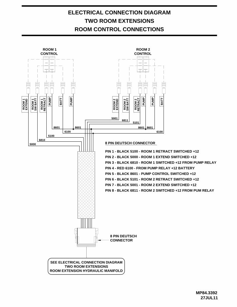
ELECTRICAL CONNECTION DIAGRAM
TWO ROOM EXTENSIONS
ROOM CONTROL CONNECTIONS
8 PIN DEUTSCH CONNECTOR
PIN 1 - BLACK 5100 - ROOM 1 RETRACT SWITCHED +12
PIN 2 - BLACK 5000 - ROOM 1 EXTEND SWITCHED +12
PIN 3 - BLACK 6810 - ROOM 1 SWITCHED +12 FROM PUMP RELAY
PIN 4 - RED 6100 - FROM PUMP RELAY +12 BATTERY
PIN 5 - BLACK 8601 - PUMP CONTROL SWITCHED +12
PIN 6 - BLACK 5101 - ROOM 2 RETRACT SWITCHED +12
PIN 7 - BLACK 5001 - ROOM 2 EXTEND SWITCHED +12
PIN 8 - BLACK 6811 - ROOM 2 SWITCHED +12 FROM PUM RELAY
8 PIN DEUTSCHCONNECTOR
SEE ELECTRICAL CONNECTION DIAGRAMTWO ROOM EXTENSIONS
ROOM EXTENSION HYDRAULIC MANIFOLD
PU
MP
6100
8601
PU
MP
BA
TT
5101
RE
TR
AC
TR
OO
M 2
8601
68115001
RO
OM
2S
W B
AT
T
RO
OM
2E
XT
EN
D
EX
TE
ND
RO
OM
1
PU
MP
SW
BA
TT
RO
OM
1
RO
OM
1R
ET
RA
CT
BA
TT
PU
MP
5000
6810
5100
8601 8601
6100
ROOM 1CONTROL CONTROL
ROOM 2
MP84.343325JUL11
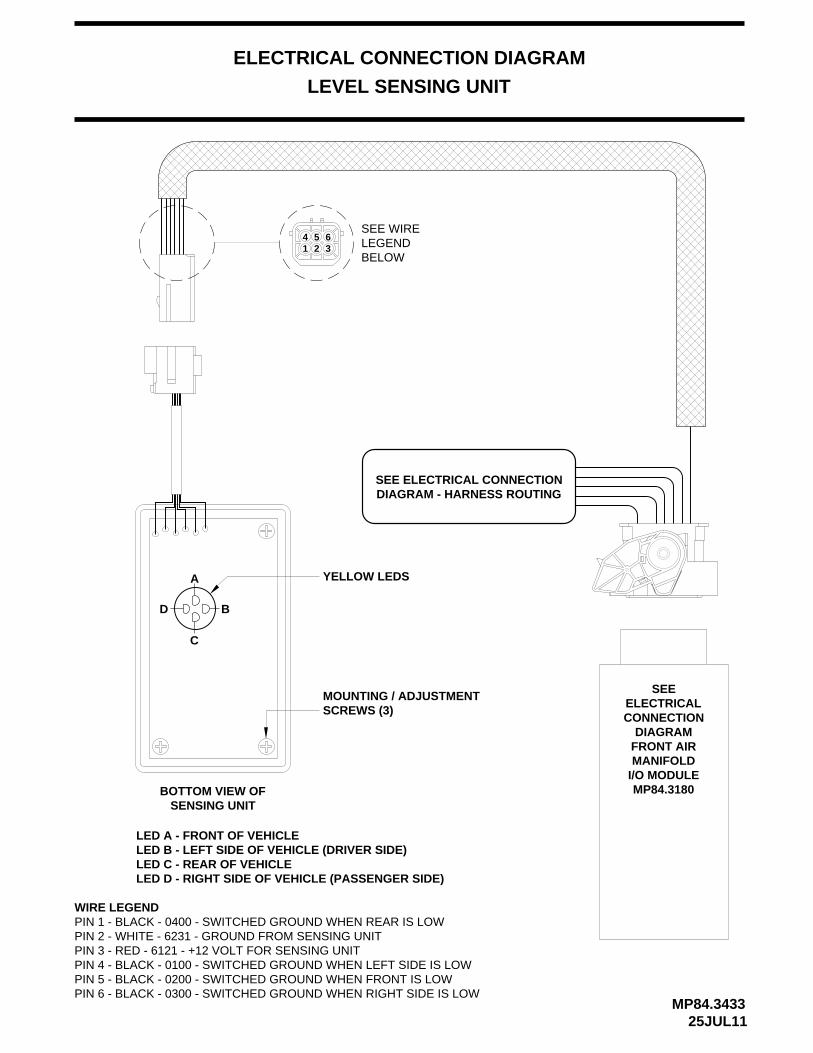
LEVEL SENSING UNIT
ELECTRICAL CONNECTION DIAGRAM
1 2 3654
SEE WIRELEGENDBELOW
SEEELECTRICALCONNECTION
DIAGRAMFRONT AIRMANIFOLD
I/O MODULEMP84.3180
SEE ELECTRICAL CONNECTIONDIAGRAM - HARNESS ROUTING
MOUNTING / ADJUSTMENTSCREWS (3)
A
BD
C
YELLOW LEDS
BOTTOM VIEW OFSENSING UNIT
LED A - FRONT OF VEHICLELED B - LEFT SIDE OF VEHICLE (DRIVER SIDE)LED C - REAR OF VEHICLELED D - RIGHT SIDE OF VEHICLE (PASSENGER SIDE)
WIRE LEGENDPIN 1 - BLACK - 0400 - SWITCHED GROUND WHEN REAR IS LOWPIN 2 - WHITE - 6231 - GROUND FROM SENSING UNITPIN 3 - RED - 6121 - +12 VOLT FOR SENSING UNITPIN 4 - BLACK - 0100 - SWITCHED GROUND WHEN LEFT SIDE IS LOWPIN 5 - BLACK - 0200 - SWITCHED GROUND WHEN FRONT IS LOWPIN 6 - BLACK - 0300 - SWITCHED GROUND WHEN RIGHT SIDE IS LOW

COMPRESSOR HARNESS FROM
NORMALLY OPEN AIR SOLENOID (1)
COMPRESSOR DIAGRAM
12 VOLT RELAY (2)
AIR FILTER
25JUL11MP84.6085
AIR LINE TO SUSPENSIONCHECK VALVE (3)
GRAY FROM AIR SOLENOID
GROUND
FUSE15 AMP
FLOW
GROUND TO RELAY MOUNTING BOLT
TO +12 BATTERYPOWER - 6100
The control box sends a +12 signal to the normally open12 volt relay. The 12 volt relay (2) will energize and thecompressor will run. The normally open air solenoid (1) will close allowing the compressor to build pressure.
The normally open air solenoid (1) will open any time the compressor is not running, allowing internal pressure & moisture to bleed off. The check valve (3) will keep thesuspension air from bleeding back to the compressor.
ELECTRICAL CONNECTION DIAGRAM
FRONT AIR MANIFOLD I/O MODULE - (BLACK) 9700

MP84.608625JUL11
BLACK ( GROUND )
RED +12
GROUNDWHITE
(GROUND)
(+12 SIGNAL)
15 AM
P
+12 VOLTBATTERY POWER
NORMALLY OPEN12 VOLT AIR SOLENOID
12 VOLTESSEX RELAY
COMPRESSOR HARNESSFROM FRONT AIR
I/O MODULE+12 SIGNAL - 9700
COMPRESSOR MOTORFUSE15 AMP
(A)
RELAY MTG. BOLT
6100
AIR COMPRESSORELECTRICAL CONNECTION DIAGRAM

ELECTRICAL CONNECTION DIAGRAM
MP84.619505OCT11
AIR / HYDRAULIC LEVELING SYSTEM
TOUCH PANEL CONNECTIONS
LINK LIGHT
GROUND FROM CONTROL MODULECAN SHIELDCAN LOWCAN HIGHYELLOW
GREEN
WIRECOLOR
4321
WHITE
PIN #NUMBER
6230
WIRE WIRE DESCRIPTION AND FUNCTION
PIN 1
SWITCHED BATTERY FROM CONTROL MODULE6800RED5
DO NOT CUTTERMINATING
RESISTOR
NOTE: THERE IS A 120 OHM TERMINATING RESISTOR AT EACHEND OF THE TOUCH PANEL HARNESS. DO NOT REMOVE, CUTOR MODIFY THE HARNESS.
TOUCH PANEL HARNESS
HWH COMPUTERIZED LEVELING
WARNING!UNDERSTAND OPERATOR’S MANUAL BEFORE USING. BLOCK FRAME AND TIRES
SECURELY BEFORE REMOVING TIRES OR CRAWLING UNDER VEHICLE.
EMERGENCYSTOP
MODETRAVEL
LEVEL
MODETRAVEL
RAISE
BRAKEPARK/
SLOPEEXCESS
NOT IN
DUMP
AIR
PIN 4 PIN 1
PIN 6
CN2
PIN 3
6110 7699
CN1
CN1
CN21 - 3 - 4 - 6 NO CONNECTION2 RED 6110 +12 SUPPLY
SWITCHED GROUND WARNING LIGHT CONTROLBLACK5 7699
REVERSEPOLARITY
LED DO NOT
LIGHTWARNINGMASTER

MP84.999928FEB11
VALVE RELEASE NUT
NOTE: When opening the valve DO NOT turn the valve release nut more than 4 and 1/2 turns counter clockwise.
OIL LEVEL
1/4" NUT DRIVER
THE BREATHER CAP ISLOCATED ON THE TOP
TOP OF THE RESERVOIR. BEFORE RETURNING THE
BREATHER CAP TO THE RESERVOIR, REMOVE ANY
VALVE RELEASE NUT
counter clockwise. Damage to nut more than 2 full turns
NOTE: When opening the valve DO NOT turn the valve release
REMOVE TO GAINACCESS TO THE 1/4"VALVE RELEASE NUT
2 1/4" DIAMETER SOLENOID VALVE
1 1/2" DIAMETER SOLENOID VALVE
GROOVES
SIDE OF THE POWER UNIT RESERVOIR
NOTE: The cam release may berotated in any direction on thevalve. DO NOT assume thatpushing down will open the
1 1/2" DIAMETER SOLENOID VALVE
valve. Pushing the cam in the
2 1/4" DIAMETER SOLENOID VALVE
the valve may result.
Damage to the valve mayFILL BETWEEN
SOLENOID VALVES WITH CAM RELEASE
wrong direction could damagethe valve.
NOTE: The cam release may berotated in any direction on thevalve. DO NOT assume thatpushing down will open the valve. Pushing the cam in the wrong direction could damagethe valve.
result.
a large style 12 volt valve with a large stylevalve with a small style 12 volt valve. Replace
considered when replacing any HWH hydraulicsolenoid valve. Replace a small style 12 volt
Valve size and voltage are still factors to be
replacements for all previous styles ofThe cam release style valves are direct
HWH hydraulic solenoid valves.
12 volt valve. This is true for 24 volt valvesalso.
turn out the old valve, confirm that no o-ring
stress on the wires at the point where they
the wires to the valve body to keep the wiresexit the valve body. Use a wire tie to secure
After installing the valve and without creating
Valve installation has not changed, simply
debris has been left in the manifold blockand turn in the new valve.
from being pinched beneath the cammechanism during operation.
WIRE TIE
WIRE TIE
HYDRAULIC SOLENOID VALVEINFORMATION INSERT
INDENTIFICATION - MANUAL OPERATIONS - REPLACEMENT
Manual retractVALVE OPENCAM RELEASE
CAM RELEASE
Default positionVALVE CLOSED
CAM RELEASE
Default positionVALVE CLOSED
position
CAM RELEASEVALVE OPEN
positionManual retract
REPLACEMENT VALVES MAY HAVE A VALVE RELEASE NUT OR RELEASE CAM
SOLENOID VALVES WITH 1/4" NUT RELEASE
1/4" NUT DRIVER, CLEAN ANY DEBRIS FROM THE
CAP, EITHER TO CHECK THE OIL LEVEL OR TO USE
IMPORTANT: PRIOR TO REMOVING THE BREATHER
INCLUDING DEBRIS INSIDE THE 1/4" NUT DRIVER.
PLASTIC PLUG:
PAINT CHIPS OR OTHER DEBRIS FROM THE DIPSTICK


![H]HWH 6XUURXQGLQJ DUHD RI WKH VWDWLRQ](https://static.fdocuments.net/doc/165x107/629ac03469a3fb1c9d28da03/hhwh-6xuurxqglqj-duhd-ri-wkh-vwdwlrq.jpg)