SYS*STIM @208/208A, MODEL ME 208/208A )/o 3 j 0 j 7 ... · 510(K) SUMMARY Submitter’s Name:...
12
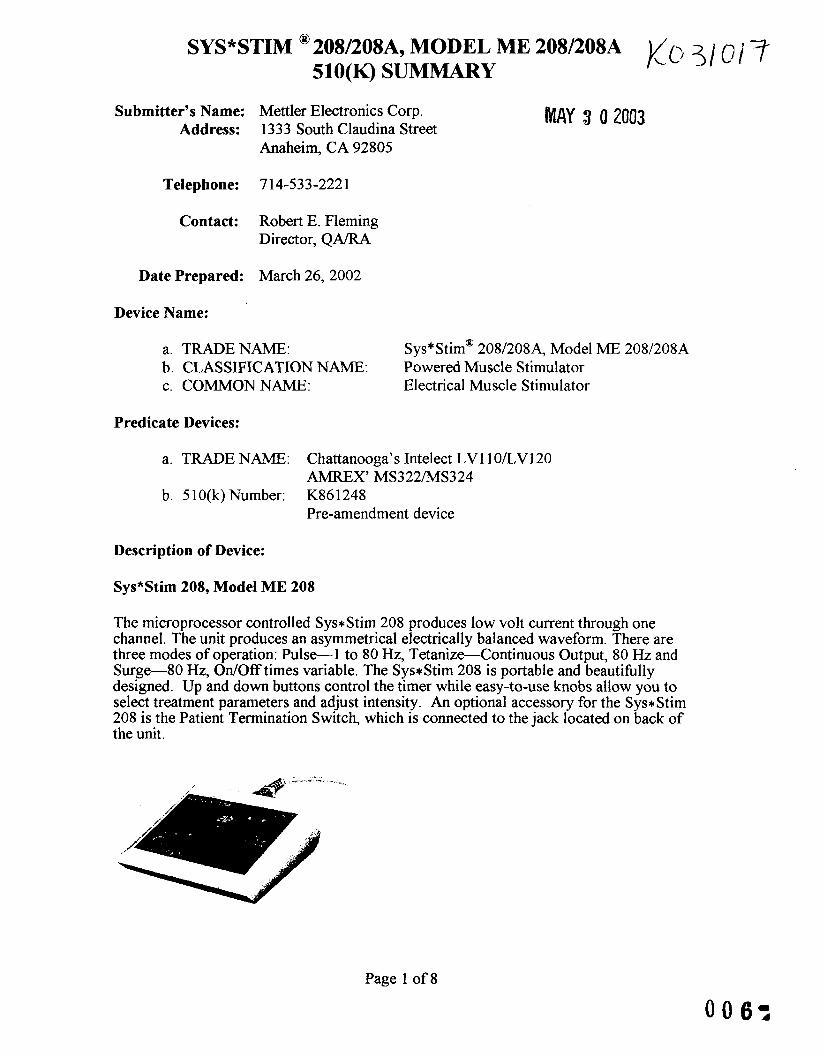
SYS*STIM @208/208A, MODEL ME 208/208A )/o 3 j 0 j 7 510(K) SUMMARY MAY 3 0 2003 Submitter’s Name: Mettler Electronics Corp. Address: 1333 South Claudina Street Anaheim, CA 92805 Telephone: 714-533-222 1 Contact: Robert E, Fleming Director, QA/RA Date Prepared: March 26,2002 Device Name: a. TRADENAME: b. CLASSIFICATION NAME: Powered Muscle Stimulator c. COMMONNAME: Electrical Muscle Stimulator Sys*Stim@ 208/208A, Model ME 208/208A Predicate Devices: a. TRADE NAME: b. 5 1 O(k) Number: Chattanooga’s Intelect LVllO/LV120 AMREX’ MS322MS324 K86 1248 Pre-amendment device Description of Device: Sys*Stim 208, Model ME 208 The microprocessor controlled Sys*Stim 208 produces low volt current through one channel. The unit produces an asymmetrical electrically balanced waveform. There are three modes of operation: Pulse-1 to 80 Hz, Tetanize-Continuous Output, 80 Hz and Surge-80 Hz, OdOff times variable. The Sys*Stim 208 is portable and beautifidly designed. Up and down buttons control the timer while easy-to-use knobs allow you to select treatment parameters and adjust intensity. An optional accessory for the Sys*Stim 208 is the Patient Termination Switch, which is connected to the jack located on back of the unit. Page 1 of 8
Transcript of SYS*STIM @208/208A, MODEL ME 208/208A )/o 3 j 0 j 7 ... · 510(K) SUMMARY Submitter’s Name:...
SYS*STIM @208/208A, MODEL ME 208/208A )/o 3 j 0 j 7 510(K) SUMMARY
MAY 3 0 2003 Submitter’s Name: Mettler Electronics Corp. Address: 1333 South Claudina Street
Anaheim, CA 92805
Telephone: 714-533-222 1
Contact: Robert E, Fleming Director, QA/RA
Date Prepared: March 26,2002
Device Name:
a. TRADENAME: b. CLASSIFICATION NAME: Powered Muscle Stimulator c. COMMONNAME: Electrical Muscle Stimulator
Sys*Stim@ 208/208A, Model ME 208/208A
Predicate Devices:
a. TRADE NAME:
b. 5 1 O(k) Number:
Chattanooga’s Intelect LVllO/LV120 AMREX’ MS322MS324 K86 1248 Pre-amendment device
Description of Device:
Sys*Stim 208, Model ME 208
The microprocessor controlled Sys* Stim 208 produces low volt current through one channel. The unit produces an asymmetrical electrically balanced waveform. There are three modes of operation: Pulse-1 to 80 Hz, Tetanize-Continuous Output, 80 Hz and Surge-80 Hz, O d O f f times variable. The Sys*Stim 208 is portable and beautifidly designed. Up and down buttons control the timer while easy-to-use knobs allow you to select treatment parameters and adjust intensity. An optional accessory for the Sys* Stim 208 is the Patient Termination Switch, which is connected to the jack located on back of the unit.
Page 1 of 8

SYS*STIM @ 208/208A, MODEL ME 208/208A 510(K) S U M W Y
-3 / cd I?
Sys*Stim 208A, Model ME 208A
The microprocessor controlled Sys*Stim 208A produces low volt current through two channels. The unit produces an asymmetrical electrically balanced waveform. There are four modes of operation: Pulse-1 to 80 Hi, Tetanize-Continuous Output, 80 Hz, S u r g e 8 0 Hi, Ordoff times variable and Recip-80 Hi, output alternates between the two channels. The Sys*Stim 208A is portable and beautiklly designed. Up and down buttons control the timer while easy-to-use knobs allow you to select treatment parameters and adjust intensity. An optional accessory for the Sys*Stim 208A is the Patient Termination Switch, which is connected to the jack located on back of the unit.
Device Intended Use Statement:
5 1 O(k) Number: Device Name: Sys*Stim@ 208/208A, Model ME 208/208A
Indications for use: 1. Symptomatic relief of chronic intractable pain, acute post traumatic pain or acute post surgical pain. 2. Temporary relaxation of muscle spasm. 3. Prevention of post-surgical phlebo-thrombosis through immediate stimulation of calf muscles. 4. Increase of blood flow in the treatment area. 5 . Prevention or retardation of disuse atrophy in post-injury type conditions. 6. Muscle re-education. 7. Maintaining or increasing range of motion.
Page 2 of 8

SYS*STIM @ 208/208A, MODEL ME 208/208A 1(o?loi? 510(K) SUMMARY
Comparison of Technological Characteristics Between Sys*Stim@ 208/208A, Model ME 208/208A and Predicate Devices:
ME 208 510 K# K K880235 Pre-amendment Device Name SyseStim 208 LV-110 MS322 Manufacturer Mettler Electronics Chattanooga AmrexZetron
1 1 0 V AC, 60 Hz 2 10% 120 V AC, 50160 Hz 120 V AC, 60 Hz Power Source Number Of Output Modes Channel(S) Synchronous Reciprocal
computerized Software Provided
Constant Current Constant Voltage Max Output Current (mA)
Max Output Voltage (v)
Waveforms 8 Channels All Channels
Output Displays Channel Isolation
Line Current Isolation
Automatic Overload Trip Automatic Over Current Trip CurrentNoltage Level
3 1 NIA NIA No NIA No Yes 184 mA peak ?200? into 500 n 72 mA peak 220% into 2 Kn 17 mA peak 220% into 10 Kf2 92 V peak 220% into 500 n 144 V peak *20% into 2 Kf2 166 peak 220% into 10 Kf2
Asymmetrical biphasic with zero net DC No In this system all the outputs are isolated from each other, they have their own amplifiers which are independent from neighboring channels or outputs. The only common thing between the outputs is the microprocessor 8 the power supply. AC power supply is converted to DC Power supply through transformer. Hence there is an insulation of mains from circuitry. From circuttry to output again there is insulation through the transformer, there by double separation between mains and the human body. No No No
3 1 NIA NIA No NIA Not stated in the manual Not stated in the manual Not Stated in the manual
3 1 NIA NIA No NIA Not stated in the manual Not stated in the manual Not Stated in the manual
110 V peak into I K ohm load load 28 V peak into 100 ohm load 28 V peak into 100 ohm load
110 V peak into 1 K ohm
Asymmetrical biphasic with zero net DC No Not Stated in the manual
Not Stated in the manual
Not Stated in the manual Not Stated in the manual Not Stated in the manual
I , Asymmetrical biphasic with zero net DC No Not Stated in the manual
Not Stated in the manual
Not Stated in the manual Not Stated in the manual Not Stated in the manual
Page 3 of 8
0087
SYS*STIM @ 208/208A, MODEL ME 208/208A 510(K) SUMMARY
No YeS Optional Remote stop
No Yes Optional Remote stop
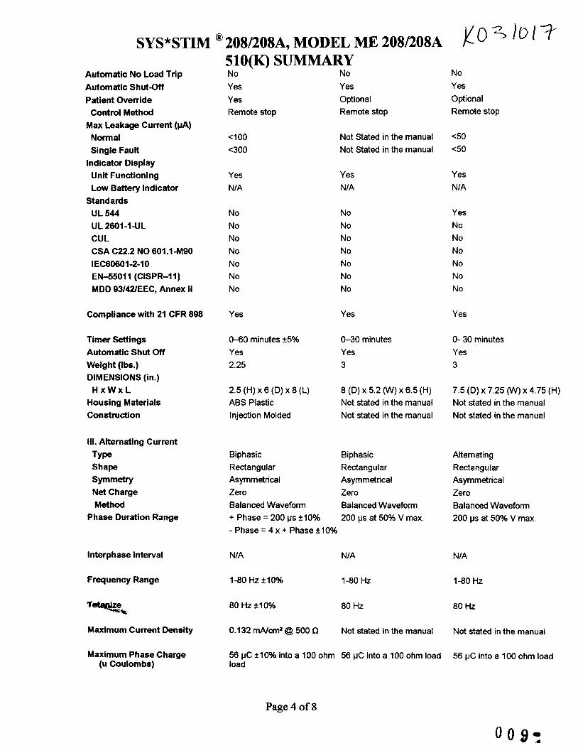
Automatic No Load Trip Automatic Shut-Off Patient Override Control Method
Max Leakage Current (pA) Normal Single Fault
Indicator Display Unit Functioning Low Battery Indicator
Standards UL 544 UL 2601-1UL CUL CSA C22.2 NO 601.1-M90 IEC60601-2-10 EN45011 (CISPR-11) MDD 93/42/EEC, Annex I I
No Yes Yes Remote stop
Not Stated in the manual Not Sated in the manual
e50 e50
4 0 0 e300
Yes NIA
Yes NIA
Yes NIA
No No No No No No No
No No No No No No No
Yes No No No No No No
Compliance with 21 CFR 898 Yes Yes Yes
Timer W i n g s Automatic Shut Off Weight (Ibs.) DIMENSIONS (in.)
H x W x L Housing Materials Construction
040 minutes +5% Yes 2.25
0-30 minutes Yes 3
0- 30 minutes Yes 3
2.5 (H) x 6 (D) x 8 (L) ABS Plastic Injection Molded
8 (D) x 5.2 (W) x 6.5 (H) Not stated in the manual Not stated in the manual
7.5 (D) x 7.25 (W) x 4.75 (H) Not stated in the manual Not stated in the manual
111. Alternating Current
Type
Symmetry
Shape
Net Charge Method
Phase Duration Range
Biphasic Rectangular Asymmetrical Zero Balanced Waveform + Phase = 200 ps f10%
Biphasic Rectangular Asymmetrical Zero Balanced Waveform 200 ps at 50% V max
Alternating Rectangular Asymmetrical Zero Balanced Waveform 200 ps at 50% V max.
- Phase = 4 x + Phase 210%
NIA NIA
1-80 Hz i l O % 1-80 HZ
80 Hz *lo% 80 Hz
0.132 WCm2 @ 500 0 Not stated in the manual
56 pC *lo% into a 100 ohm 56 pC into a 100 ohm load load
Interphase Interval NIA
Frequency Range 1-80 HZ
80 Hz
Maximum Current Density Not stated in the manual
Maximum Phase Charge (u Coulombs)
56 pC into a 100 ohm load
Page 4 of 8

500 OHMS 2K OHMS 10K OHMS Formula
SYS*STIM @ 208/208A, MODEL ME 208/208A
Maximum Power Density
Amplitude Modulation Options Surge Frequency On Times Off Times
Modulation Options a) May Be Selected
Independently Or Together
b) Simultaneously For Each Channel Pair
c) Independent Controls For Each Channel
510(K) SUMMARY 33.5 210% 13.1 210% 3.4 +lo% q = l x t
Not stated in the manual Not stated in the manual Not stated in the manual Not stated in the manual
0.012 Wlcm2 @ 500 n Not stated in the manual
80 Hz 210% 80 Hz 0.375 to 3.75 seconds 210% 0.375 to 75 seconds 0.375 to 3.75 seconds *lo% 0.375 to 3.75 seconds
NIA NIA
NIA
NIA
NIA
NIA
Not stated in the manual Not stated in the manual Not stated in the manual Not stated in the manual
Not stated in the manual
80 Hz 0.375 to 75 seconds 0.375 to 3.75 seconds
NIA
NIA
NIA
Note 1: The Current denslty and Power density have been calculated using Average Current. Average Current = (Pulse Width I Pulse Frequency ) Peak Current where Pulse Width and Pulse Frequency is in microseconds Pulse Width = 182 microseconds @ 500 Ohms, Observed on CRO Pulse Frequency = 12500 microseconds (80 Hz - Maximum Frequency)
equation for maximum phase charge
Current = ( Output Voltage / 500 Ohms) Phase Charge = Pulse Width x Current (peak to peak)
equation for maximum current density resistance)
Current Denslty = (Pulse On period I Total Pulse period) x (Voltage I
equation for Power Densty Power Densrty = Current Density x Output Voltage
Page 5 of 8
010:

SYS*STIM @208/208~ , MODEL ME 2 0 8 / 2 0 8 ~ )C 0 3 i 0 17 510(K) SUMMARY
,
ME 208A
510 K # K K880235 Pre-amendment Device Name Sys*Stim 208A LV-120 MS324 Manufacturer Mettler Electronics Chattanooga Amrex-Zetron Power Source 110 V AC, 60 Hz 510% 120 V AC, 50160 Hz 120 V AC, 60 Hz Number Of Output Modes 4 4 4 Channel(S) 2 2 2 Synchronous Yes Yes Yes Reciprocal Yes Yes Yes
Software Provided NIA NIA NIA Computerized No No No
Constant Current No Not stated in the manual Not stated in the manual Constant Voltage Yes Not stated in the manual Not stated in the manual Max Output Current (mA) Not Stated in the manual 184 mA peak 520% into 500 Not Stated in the manual
n 72 mA peak 220% into 2 Kf2 17 mA peak +20% into 10 Kf l 92 V peak 520% into 500 n 110 V peak into 1K ohm 144 V peak k20% into 2 Kn load load 166 peak+20% into 10 Kn 28 V peak into 100 ohm load 28 V peak into 100 ohm load
Max Output Voltage (V) 110 V peak into 1K ohm
Waveforms 8 Channels All Channels
Output Displays Channel Isolation
Line Current Isolation
Automatic Overload Trip Automatic Over Current Trip
CurrenWoItage. Level Automatic No Load Trip Automatic Shut-Off
... %
Asymmetrical biphasic with zero net DC No No In this system all the outputs Not Stated in the manual are isolated from each other, they have their own amplifiers which are independent from neighboring channels or outputs. The only common thing between the outputs is the microprocessor & the power supply. AC power supply is converted to DC Power supply through transformer. Hence there is an insulation of mains from circuitry. From circuitry to output again there is insulation through the transformer, there by double separation between mains and the human body. No No No No No Yes Yes
Asymmetrical biphasic with zero net DC
Not Stated in the manual
Not Stated in the manual Not Stated in the manual Not Stated in the manual
Page 6 of 8
Asymmetrical biphasic with zero net DC No Not Stated in the manual
Not Stated in the manual
Not Stated in the manual Not Stated in the manual Not Stated in the manual No Yes
SYS*STIM @ 208/208A, MODEL ME 208/208A
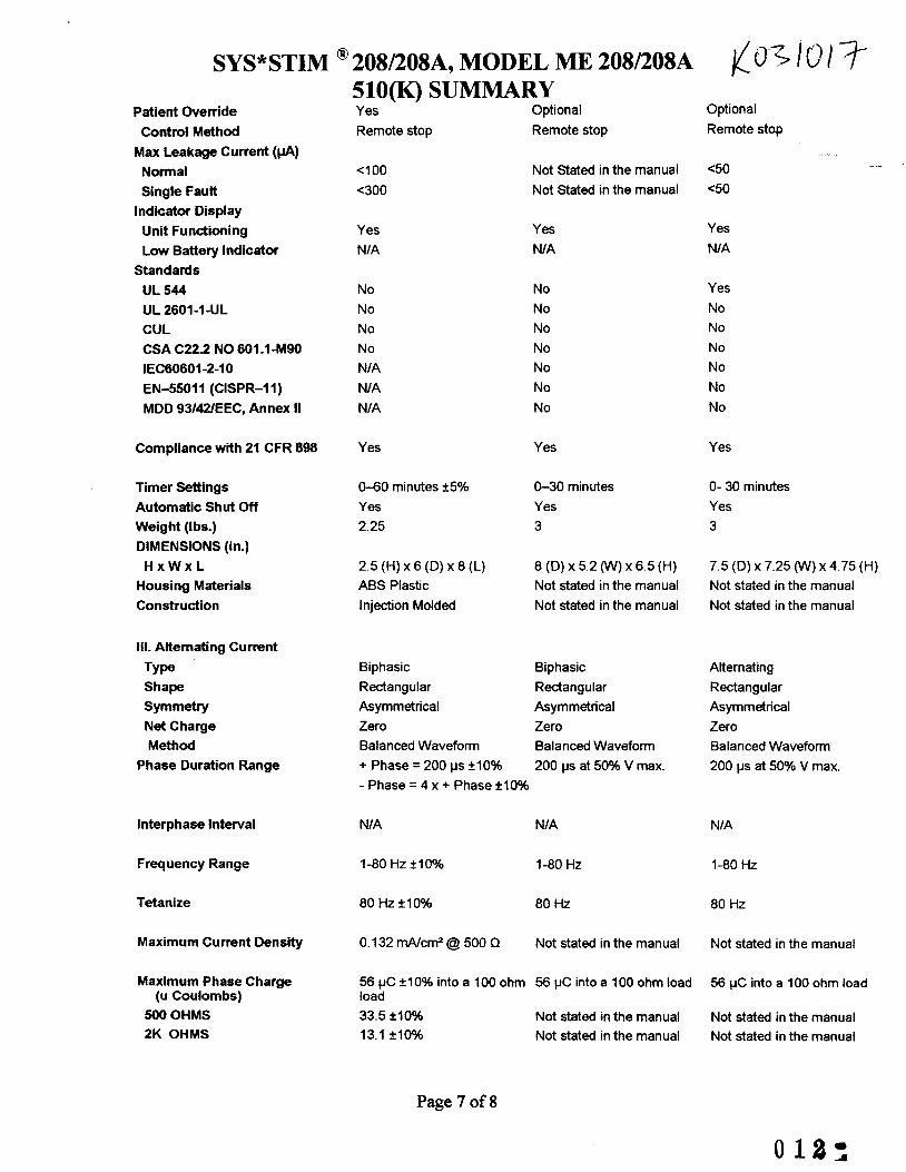
Patient Override Control Method
Max Leakage Current (PA) Normal Single Fault
Unit Functioning Low Battery Indicator
Standards UL 544 UL 2601-1-UL CUL CSA C22.2 NO 601 -1490 IEC60601-2-10 EN45011 (CISPR-11)
Indicator Display
MDD 93/42/EEC. Annex II
Compliance with 21 CFR 898
Timer Settings Automatic Shut Off Weight (I bs.) DIMENSIONS (in.)
H x W x L Housing Materials Construction
111. Alternating Current
Type Shape
Symmetry Net Charge Method
Phase Duration Range
Interphase Interval
Frequency Range
Tetanize
Maximum Current Density
Maximum Phase Charge (u Coulombs)
500 OHMS 2K OHMS
Optional 510(K) SUMMARY Yes Optional Remote stop Remote stop Remote stop
4 0 0 <300
Yes NIA
No No No No N/A NIA NIA
Not Stated in the manual Not Stated in the manual
6 0 4 0
Yes NIA
No No No No No No No
Yes NIA
Yes No No No No No No
Yes Yes Yes
0-60 minutes +5% 0-30 minutes Yes Yes 2.25 3
0- 30 minutes Yes 3
2.5 (H) x 6 (D) x 8 (L) ABS Plastic Injection Molded
8 (D) x 5.2 (W) x6.5 (H) Not stated in the manual Not stated in the manual
7.5 (D) x 7.25 (W) x 4.75 (H) Not stated in the manual Not stated in the manual
Biphasic Biphasic Alternating Rectangular Rectangular Rectangular Asymmetrical Asymmetrical Asymmetrical Zero Zero Zero Balanced Waveform Balanced Waveform Balanced Waveform + Phase = 200 ps &lo% 200 ps at 50% V max. - Phase = 4 x + Phase &lo%
200 ps at 50% V max.
NIA NIA NIA
1-80 Hz +lo% 1-80 HZ 1-80 HZ
80 Hz *IO% 80 Hz 80 Hz
0.132 W c m Z @ 500 0 Not stated in the manual Not stated in the manual
56 pC +IO% into a 100 ohm 56 pC into a 100 ohm load load 33.5 *lo% Not stated in the manual 13.1 &lo% Not stated in the manual
56 pC into a 100 ohm load
Not stated in the manual Not stated in the manual
Page 7 of 8

SYS*STIM @ 208/208A, MODEL ME 208/208A 510(K) SUMMARY
) c ~ - ~ l ~ [ 7 10K OHMS 3.4 ?lo% Not stated in the manual Not stated in the manual
Formula q = l x t Not stated in the manual Not stated in the manual
Maximum Power Density 0.012 W l M @ 500 Q Not stated in the manual Not stated in the manual
Amplitude Modulation Options Surge Frequency On Times Off Times Recip Frequency On Times Off Times
Modulation Options a) May Be Selected
Independently Or Together
b) Simultaneously For Each Channel Pair
c) Independent Controls For Each Channel
80 HZ +lo% 80 Hz 80 Hz 0.375 to 3.75 seconds 210% 0.375 to 3.75 seconds 0.375 to 3.75 seconds +looh 0.375 to 3.75 seconds
0.375 to 3.75 seconds 0.375 to 3.75 seconds
80 Hz ?lo% 80 Hz 80 Hz 0.375 to 3.75 seconds +lo% 0.375 to 3.75 seconds 0.375 to 3.75 seconds r10% 0.375 to 3.75 seconds
0.375 to 3.75 seconds 0.375 to 3.75 seconds
NIA NIA NIA
NIA
NIA
NIA
NIA
NIA
NIA
Note 1: The Current density and Power density have been calculated using Average Current. Average Current = (Pulse Width I Pulse Frequency ) * Peak Current where Pulse Width and Pulse Frequency is in microseconds Pulse Width = 182 microseconds @ 500 Ohms, Observed on CRO Pulse Frequency = 12500 microseconds (80 Hz - Maximum Frequency)
equation for maximum phase charge
Current = ( Output Voltage I 500 Ohms) Phase Charge = Pulse Width x Current (peak to peak)
equation for maximum current density resistance)
Current Density = (Pulse On period I Total Pulse period) x (Voltage /
equation for Power Denslty Power Density = Current Density x Output Voltage
Page 8 of 8
0132

DEPARTMENT OF HEALTH & HUMAN SERVICES Public Health Service
Food and Drug Administration 9200 Corporate Boulevard Rockville MD 20850
Mr. Robert E. Fleming Director, QNRA Official Correspondent Mettler Electronics Corp. 1333 South Claudina Street Anaheim, California 92805
Re: KO31017 Trade/Device Name: Sys*Stim@ 208 and 208A Regulation Number: 2 1 CFR 882.5890, 890.5850 Regulation Name: Transcutaneous electrical nerve stimulator for pain relief, Powered
Regulatory Class: I1 Product Code: IPF, GZJ Dated: March 28,2003 Received: March 3 1,2003
muscle stimulator
Dear Mr. Fleming:
We have reviewed your Section 5 1 O(k) premarket notification of intent to market the device referenced above and have determined the device is substantially equivalent (for the indications for use stated in the enclosure) to legally marketed predicate devices marketed in interstate commerce prior to May 28, 1976, the enactment date of the Medical Device Amendments, or to devices that have been reclassified in accordance with the provisions of the Federal Food, Drug, and Cosmetic Act (Act) that do not require approval of a premarket appcoval application (PMA). You may, therefore, market the device, subject to the general controls provisions of the Act. The general controls provisions of the Act include requirements for annual registration, listing of devices, good manufacturing practice, labeling, and prohibitions against misbranding and adulteration.
If your device is classified (see above) into either class I1 (Special Controls) or class I11 (PMA), it may be subject to such additional controls. Existing major regulations affecting your device can be found in the Code of Federal Regulations, Title 21, Parts 800 to 898. In addition, FDA may publish fwrther announcements concerning your device in the Federal Register.
Please be advised that FDA's issuance of a substantial equivalence determination does not mean that FDA has made a determination that your device complies with other requirements of the Act or any Federal statutes and regulations administered by other Federal agencies. You must comply with all the Act's requirements, including, but not limited to: registration and listing (2 1 CFR Part 807); labeling (21 CFR Part 801); good manufacturing practice requirements as set
Page 2 - Mr. Robert E. Fleming
forth in the quality systems (QS) regulation (2 I CFR Part 820); and if applicable, the electronic product radiation control provisions (Sections 53 1-542 of the Act); 2 1 CFR 1000- 1050. This letter will allow you to begin mprketing your device as described in your Section 5 1 O(k) premarket notification. The FDA finding of substantial equivalence of your device to a legally marketed predicate device results in a classification for your device and thus, permits your device to proceed to the market.
If you desire specific advice for your device on our labeling regulation (2 1 CFR Part 80 l), please contact the Office of Compliance at (301) 594-4659. Also, please note the regulation entitled, "Misbranding by reference to premarket notification" (21 CFR Part 807.97). You may obtain other general information on your responsibilities under the Act from the Division of Small Manufacturers, International and Consumer Assistance at its toll-free number (800) 63 8-204 1 or (30 1) 443-6597 or at its Internet address http://www.fda.gov/cdrh/dsmddsmamain.htnd
Sincerely yours,
/&d*~ I) Celia M. Witten, Ph.D., M.D.
Director Division of General, Restorative
and Neurological Devices Office of Device Evaluation Center for Devices and
Radiological Health
Enclosure

Attachment Ib
Pare of
5 10(k) Number (if known): KO31017
Device Name: Svs*Stim 208 ME208)
Indications For Use:
1.
2. 3. 4. 5. 6. 7.
Symptomatic relief of chronic intractable pain, acute post traumatic pain or acute post surgical pain Temporary relaxation of muscle spasm Prevention of post-surgical phlebc+thrombosis through immediate siimulation of calf muscles Increasing local blood circulation Prevention or retardation of disuse atrophy Muscle re-education Maintaining or increasing range of motion
(PLEASE DO NOT WRITE BELOW THIS ____-__
and Neurdc,r::a! L/pvrices
Prescription Use J (Per 21 CFR 801.109)
5 1 O(k) Number & 0 ~ I S l ~ ver-T e- oun er Use OR
(Optional Format I -2-%)

Attachment 1 b
Page of
5 lO(k) Number (if known): KO3 10 17
Device Name: Svs+Stim 208A Mf3208A)
Indications For Use:
1. Symptomatic relief of chronic intractable pain, acute post traumatic pain or acute post surgical
2. Temporary relaxation of muscle spasm 3. Prevention of post-surgical phlebo-thrombosis through immediate &mulation of calf muscles 4. Increasing local blood circulation 5. Prevention or retardation of disuse atrophy 6. Muscle re-education 7. Maintaining or increasing range of motion
pain
(PEASE DO NOT WRITE BELOW THIS LINE - CONTINUE ON ANOTHER PAGE IF NEEDED) __._I____._____-_-______________________--------
and Neurological Devices
Prescription Use .$ (Per 21 CFR 801.109)
5 1 O(k) Number OR Over-The-Counter Use
(Optional Format 1 -2-%)