
Syllabus - Meerut Institute of Technology - Meerutmitmeerut.ac.in/Docs/M.D-I final Tutorial and...
16
Syllabus NME-501 : MACHINE DESIGN-I UNIT I Introduction Definition, Design requirements of machine elements, Design procedure, Standards in design, Selection of preferred sizes, Indian Standards designation of carbon & alloy steels, Selection of materials for static and fatigue loads. 3 Design for Static Load Modes of failure, Factor of safety, Principal stresses, Stresses due to bending and torsion, Theory of failure. UNIT II Design for Fluctuating Loads Cyclic stresses, Fatigue and endurance limit, Stress concentration factor, Stress concentration factor for various machine parts, Notch sensitivity, Design for finite and infinite life, Soderberg, Goodman & Gerber criteria. Riveted Joints Riveting methods, materials, Types of rivet heads, Types of riveted joints, Caulking and Fullering, Failure of riveted joint, Efficiency of riveted joint, Design of boiler joints, Eccentric loaded riveted joint. UNIT III Shafts Cause of failure in shafts, Materials for shaft, Stresses in shafts, Design of shafts subjected to twisting moment, bending moment and combined twisting and bending moments, Shafts subjected to fatigue loads, Design for rigidity. Keys and Couplings Types of keys, splines, Selection of square & flat keys, Strength of sunk key, Couplings, Design of rigid and flexible couplings. UNIT IV Mechanical Springs Types, Material for helical springs, End connections for compression and tension helical springs, Stresses and deflection of helical springs of circular wire, Design of helical springs subjected to static and fatigue loading. Power Screws Forms of threads, multiple threads, Efficiency of square threads, Trapezoidal threads, Stresses in screws, Design of screw jack Note: Design data book is allowed in the examination Books and References
Transcript of Syllabus - Meerut Institute of Technology - Meerutmitmeerut.ac.in/Docs/M.D-I final Tutorial and...
Syllabus
NME-501 : MACHINE DESIGN-I
UNIT I
Introduction Definition, Design requirements of machine elements, Design procedure, Standards in
design, Selection of preferred sizes, Indian Standards designation of carbon & alloy steels, Selection of
materials for static and fatigue loads. 3 Design for Static Load Modes of failure, Factor of safety,
Principal stresses, Stresses due to bending and torsion, Theory of failure.
UNIT II
Design for Fluctuating Loads Cyclic stresses, Fatigue and endurance limit, Stress concentration factor,
Stress concentration factor for various machine parts, Notch sensitivity, Design for finite and infinite life,
Soderberg, Goodman & Gerber criteria.
Riveted Joints Riveting methods, materials, Types of rivet heads, Types of riveted joints, Caulking and
Fullering, Failure of riveted joint, Efficiency of riveted joint, Design of boiler joints, Eccentric loaded
riveted joint.
UNIT III
Shafts Cause of failure in shafts, Materials for shaft, Stresses in shafts, Design of shafts subjected to
twisting moment, bending moment and combined twisting and bending moments, Shafts subjected to
fatigue loads, Design for rigidity.
Keys and Couplings Types of keys, splines, Selection of square & flat keys, Strength of sunk key,
Couplings, Design of rigid and flexible couplings.
UNIT IV
Mechanical Springs Types, Material for helical springs, End connections for compression and tension
helical springs, Stresses and deflection of helical springs of circular wire, Design of helical springs
subjected to static and fatigue loading.
Power Screws Forms of threads, multiple threads, Efficiency of square threads, Trapezoidal threads,
Stresses in screws, Design of screw jack
Note: Design data book is allowed in the examination Books and References

UNIT-I
MEERUT INSTITUTE OF TECHNOLOGY MEERUT
B.Tech (Mechanical) (V semester)
Subject-Machine Design-1
Assignment No-1
1. What is Machine Design? What are the steps in Machine Design process?
2. What do you mean by need analysis? Write its importance in design. (U.P.T.U
2008-09)
3. Explain the brain storming. What are their rules?
4. What is standardization? Give the advantages of standardization. (U.P.T.U
2007-08)
5. What is interchangeability?
6. Explain Concurrent Engineering.
7. What is preferred number? Derive the R-10 series.
8. Explain the importance of preferred size in design process. (U.P.T.U
2004-05)
9. Find out the number of R-20/4 (10…100) derived series.
10. Discuss the effect of silicon, manganese, sulphur and phosphorus on cast iron.
11. Designate the following materials
(a) Grey cast iron with minimum tensile strength of 300 N/mm2.
(b) Designate plain carbon steel with 0.5 % carbon and 0.85 manganese
(c) Carbon= 0.35 - 0.45 %, chromium= 0.90 - 1.1 %.
(d) Carbon 0.12 - 0.20 % , Ni= 0.8 -1.2 %, Cr= 0.6 – 1.0 %
(e) C=0.15 -0.25 %, Si=0.10 – 0.50 %, Mn= 0.3 – 0.5 %, Ni=2.5 – 3.5 %, Cr= 18-
24 %
(f) 50Cr1V23 U.P.T.U 2005-06)
12. Define these definitions
(a) Ductility (b) Brittleness (c) Creep (d) Fatigue (e) Elasticity (f) Plasticity (g)
Toughness (h) Resilience
13. What are the reasons for the use of alloy steel in machine parts? (U.P.T.U
2004-05)
14. What are the three basic mode of failure of mechanical component?
15. What is factor of safety? Why is it necessary to use factor of safety.
16. What are the factors to be considered for deciding the magnitude of factor of safety?
17. Explain different types of theories of failure in machine design.
18. Explain the importance of material selection decision in machine design. (U.P.T.U
2008-09)
19. Discuss the factors which are considered in the selection of a material for a machine
component.
20. Enumerate advantages and disadvantages of plastic material over metals. (U.P.T.U
2007-08)
UNIT-II

MEERUT INSTITUTE OF TECHNOLOGY MEERUT
B.Tech (Mechanical) (V semester)
Subject-Machine Design-1
Tutorial No-1
1. A forged steel bar 50 mm in diameter is subjected to
reversed bending stress of 250 N/mm2. The bar is made
of steel 40C8 (Sut=600 N/mm2). Calculate the life of the
bar for a reliability of 90 %. Ans=23736 Cycle
2. A rotating beam made of steel 45C8 (Sut=630 N/mm2) is
subjected to completely reversed bending stress. The
corrected endurance limit of the bar is 315 N/mm2.
Calculate the fatigue strength of the bar for a life of
90,000 cycle.
3. A machine component is subjected to a flexural stress
which fluctuates between + 300 MN/m2 and – 150
MN/m2. Determine the value of minimum ultimate
strength according to 1. Gerber relation; 2.Goodman
relation; and 3. Soderberg relation. Take yield strength
= 0.55 Ultimate strength; Endurance strength = 0.5
Ultimate strength; and factor of safety = 2.
4. A bar of circular cross-section is subjected to alternating
tensile forces varying from a minimum of 200 kN to a
maximum of 500 kN. It is to be manufactured of a
material with an ultimate tensile strength of 900 MPa
and an endurance limit of 700 MPa. Determine the
diameter of bar using safety factors of 3.5 related to
ultimate tensile strength and 4 related to endurance limit
and a stress concentration factor of 1.65 for fatigue load.
Use Goodman straight line as basis for design.
5. Determine the thickness of a 120 mm wide uniform
plate for safe continuous operation if the plate is to be
subjected to a tensile load that has a maximum value of
250 kN and a minimum value of 100 kN. The properties
of the plate material are as follows: Endurance limit
stress is 225 MPa, and Yield point stress is 300 MPa.
The factor of safety based on yield point may be taken
as 1.5.
6. Determine the diameter of a circular rod made of
ductile material with a fatigue strength (complete
stress reversal), σe = 265 MPa and a tensile yield
strength of 350 MPa. The member is subjected to a
varying axial load from Wmin = –300×103 N to
Wmax=700×103
N and has a stress concentration
factor = 1.8. Use factor of safety as 2.0.
7.
8.
7. A steel rod is subjected to a reversed axial load of
180 kN. Find the diameter of the rod for a factor
of safety of 2. Neglect column action. The
material has an ultimate tensile strength of 1070
MPa and yield strength of 910 MPa. The
endurance limit in reversed bending may be
assumed to be one-half of the ultimate tensile
strength. Other correction factors may be taken as
follows:For axial loading = 0.7; For machined
surface = 0.8 For size = 0.85 ; For stress
concentration = 1.0.
8. A circular bar of 500 mm length is supported
freely at its two ends. It is acted upon by a central
concentrated cyclic load having a minimum value
of 20 kN and a maximum value of 50 kN.
Determine the diameter of bar by taking a factor
of safety of 1.5, size effect of 0.85, surface finish
factor of 0.9. The material properties of bar are
given by : ultimate strength of 650 MPa, yield
strength of 500 MPa and endurance strength of
350 MPa.
9. A piston rod of circular cross section is subjected
to a cyclic load fluctuating between 15 kN in
compression to 25 kN in tension. The endurance
limit for the piston rod material is 360 N/mm2.
While yield strength is 400 N/mm2. The impact
factor is 1.25 while fos is 1.5. The surface finish
factor and stress concentration factor are 0.88 and
2.25 respectively. Determine the diameter of
piston rod. d=20.70 mm
10. A 50 mm diameter shaft is made from carbon
steel having ultimate tensile strength of 630 MPa.
It is subjected to a torque which fluctuates
between 2000 N-m to – 800 N-m. Using
Soderberg method, calculate the factor of safety.
Assume suitable values for any other data Needed
11. A simply supported beam has a concentrated load
at the centre which fluctuates from a value of P to
4 P. The span of the beam is 500 mm and its
cross-section is circular with a diameter of 60
mm. Taking for the beam material an ultimate
stress of 700 MPa, a yield stress of 500 MPa,
endurance limit of 330 MPa for reversed bending,
and a factor of safety of 1.3, calculate the
maximum value of P. Take a size factor of 0.85
and a surface finish factor of 0.9.
UNIT-III

MEERUT INSTITUTE OF TECHNOLOGY MEERUT
B.Tech (Mechanical) (V semester)
Subject-Machine Design-1
Tutorial No-2
1. A solid shaft is transmitting 1 MW at 240 r.p.m.
Determine the diameter of the shaft if the maximum
torque transmitted exceeds the mean torque by 20%.
Take the maximum allowable shear stress as 60 MPa.
. Ans: d=160 mm
2. A cylindrical shaft made of steel of yield strength
700 MPa is subjected to static loads consisting of a
bending moment of 10 kN-m and a torsional moment
of 30 kN-m. Determine the diameter of the shaft
using two different theories of failure and assuming a
factor of safety of 2. Ans. 100 mm
3. Find the diameter of a solid steel shaft to transmit 20
kW at 200 r.p.m. The ultimate shear stress for the
steel may be taken as 360 MPa and a factor of safety
as 8.If a hollow shaft is to be used in place of the
solid shaft, find the inside and outside diameter when
the ratio of inside to outside diameters is 0.5.
Ans: d=50 mm do = 50mm di=25 mm
4. A line shaft rotating at 200 r.p.m. is to transmit 20
kW. The shaft may be assumed to be made of mild
steel with an allowable shear stress of 42 MPa.
Determine the diameter of the shaft, neglecting the
bending moment on the shaft . Ans: d=50 mm
5. A solid circular shaft is subjected to a bending
moment of 3000 N-m and a torque of 10 000 N-m.
The shaft is made of 45 C 8 steel having ultimate
tensile stress of 700 MPa and a ultimate shear stress
of 500 MPa. Assuming a factor of safety as 6,
determine the diameter of the shaft. Ans: d=90 mm
6. A line shaft rotating at 200 r.p.m. is to transmit 20
kW. The allowable shear stress for the material of the
shaft is 42 MPa. If the shaft carries a central load of
900 N and is simply supported between bearing 3
metre apart, determine the diameter of the shaft. The
maximum tensile or compressive stress is not to
exceed 56 MPa. Ans. d=50 mm
7. A propeller shaft is required to transmitted 45 KW
power at 500 r.p.m. its hollow shaft having an inside
diameter 0.6 times of outside diameter. It’s made of
plain carbon steel and the permissible shear stress is
84 N/mm2. Calculate the inside and outside diameter
of the shaft. Ans: di=23.47 mm do=39.12 mm
8. Derived the diameter of a hollow shaft with a ratio of
of 0.8, capable of transmitting 300 KW at 225
rev/min. when subjected to a maximum bending
moment of 5500 Nm, the load is suddenly applied with
minor shock for torsional moment the bending moment
is steady and the allowable shearing stress is 56 MPa.
Ans: di=120 mm do=150 mm
9. A shaft made of mild steel is required to transmit 100
kW at 300 r.p.m. The supported length of the shaft is 3
meters. It carries two pulleys each weighing 1500 N
supported at a distance of 1 metre from the ends
respectively. Assuming the safe value of stress,
determine the diameter of the shaft. Ans: d=70 mm
10. A hollow circular shaft of outer and inner diameter of
do and di respectively is subjected to a torsional
moment of M over a length l. The permissible angle of
twist is θ degree. Proved that the shaft diameter is
given by.
d0 =
11. A rotating shaft 40 mm in diameter, is made of steel
FeE 580 (Syt=580 N/mm2). It is subjected to a steady
torsional moment of 250 N-m and bending moment of
1250 N-m. Calculate the factor of safety available
based on Ans. (i) 2.89, (ii) 2.86
(i) Maximum principal stress theory
(ii) Maximum shear stress theory
12. A Propeller shaft is required to transmit 50 kW power
at 600 rpm. It is hollow shaft. Having inside diameter
0.8 times of the outer diameter. It is made of steel (Syt
= 380 N/mm2) and the factor of safety is 4. Calculate
the inside and outside diameter of the shaft.
13. Two 400 mm diameter pulleys are keyed to a simply
supported shaft 500 mm apart. Each pulley is 100 mm
from its support and has horizontal belts, tension ratio
being 2.5. If the shear stress is to be limited to 80 MPa
while transmitting 45 kW at 900 r.p.m., find the shaft
diameter if it is to be used for the input-output belts
being on the same or opposite sides. Ans. 40 mm
14. A line shaft is driven by means of a motor placed
vertically below it. The pulley on the line shaft is 1.5
metre in diameter and has belt tensions 5.4 kN and 1.8
kN on the tight side and slack side of the belt
respectively. Both these tensions may be assumed to be
vertical. If the pulley be overhang from the shaft, the
distance of the centre line of the pulley from the centre
line of the bearing being 400 mm, find the diameter of
the shaft. Assuming maximum allowable shear stress
of 42 MPa Ans: d=78mm
15. A shaft is supported by two bearings placed 1 m apart.
A 600 mm diameter pulley is mounted at a distance of
300 mm to the right of left hand bearing and this drives
a pulley directly below it with the help of belt having
maximum tension of 2.25 kN. Another pulley 400 mm
diameter is placed 200 mm to the left of right hand
bearing and is driven with the help of electric motor
and belt, which is placed horizontally to the right. The
angle of contact for both the pulleys is 180° and µ =
0.24. Determine the suitable diameter for a solid shaft,
allowing working stress of 63 MPa in tension and 42
MPa in shear for the material of shaft. Assume that the
torque on one pulley is equal to that on the other
pulley. Ans: d=51.7mm
16. A transmission shaft with keyway is subjected to a
maximum torsional moment of 750 M-m and
maximum bending moment of 1200 N-m.the loads are
suddenly applied minor shocks are encountered, and
the allowable shear stress is 42 MPa. Find the shaft
diameter Ans: d=68.3 mm
17. A mild steel shaft transmits 20 kW at 200 r.p.m. It
carries a central load of 900 N and is simply supported
between the bearings 2.5 meters apart. Determine the
size of the shaft, if the allowable shear stress is 42 MPa
and the maximum tensile or compressive stress is not
to exceed 56 MPa. What size of the shaft will be
required, if it is subjected to gradually applied loads?
Ans: d=53.4 mm, d=57.7 mm
18. Design a shaft to transmit power from an electric motor
to a lathe head stock through a pulley by means of a
belt drive. The pulley weighs 200 N and is located at
300 mm from the centre of the bearing. The diameter
of the pulley is 200 mm and the maximum power
transmitted is 1 kW at 120 r.p.m. The angle of lap of
the belt is 180° and coefficient of friction between the
belt and the pulley is 0.3. The shock and fatigue factors
for bending and twisting are 1.5 and 2.0 respectively.
The allowable shear stress in the shaft may be taken as
35 MPa. Ans: d=51.1 mm
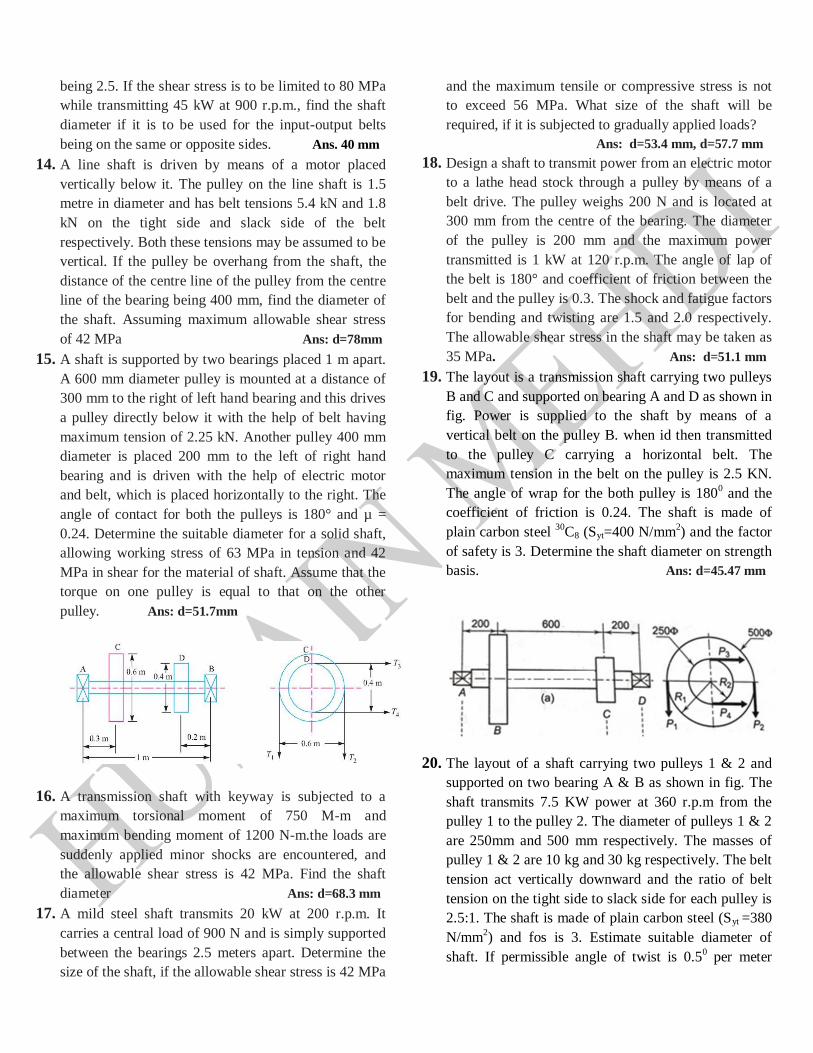
19. The layout is a transmission shaft carrying two pulleys
B and C and supported on bearing A and D as shown in
fig. Power is supplied to the shaft by means of a
vertical belt on the pulley B. when id then transmitted
to the pulley C carrying a horizontal belt. The
maximum tension in the belt on the pulley is 2.5 KN.
The angle of wrap for the both pulley is 1800 and the
coefficient of friction is 0.24. The shaft is made of
plain carbon steel 30
C8 (Syt=400 N/mm2) and the factor
of safety is 3. Determine the shaft diameter on strength
basis. Ans: d=45.47 mm
20. The layout of a shaft carrying two pulleys 1 & 2 and
supported on two bearing A & B as shown in fig. The
shaft transmits 7.5 KW power at 360 r.p.m from the
pulley 1 to the pulley 2. The diameter of pulleys 1 & 2
are 250mm and 500 mm respectively. The masses of
pulley 1 & 2 are 10 kg and 30 kg respectively. The belt
tension act vertically downward and the ratio of belt
tension on the tight side to slack side for each pulley is
2.5:1. The shaft is made of plain carbon steel (Syt =380
N/mm2) and fos is 3. Estimate suitable diameter of
shaft. If permissible angle of twist is 0.50 per meter

length. Calculate the shaft diameter on the basis of
torsional rigidity. Assume G=79300 N/mm2.
Ans: d=41.37 mm Ans:41.37 mm
21. A line shaft supporting two pulleys A and B as shown.
Power is supplied to the shaft by means of a vertical
belt on the pulley A. Which is then transmitted to the
pulley B carrying a horizontal belt. The ratio of the belt
tension on tight and loose sides is 3:1. The limiting
value of tension in the belt is 2.7 kN. The shaft is made
of plain carbon steel 40
C8 (Sut=650 N/mm2) and
(Syt=380 N/mm2). The pulleys are keyed to the shaft.
Determine the diameter of the shaft according to the
ASME code if Kb=1.5and kt=1.0 Ans: d=42.53mm
22. A steel spindle transmits 4 kW at 800 r.p.m. The
angular deflection should not exceed 0.250 per meter of
the spindle. If the modulus of rigidity for the material
of the spindle is 84 GPa. Find the diameter of the
spindle and the shear stress induced in the spindle.
. Ans: d=35 mm, τ=5.67 N/mm2
23. A line shaft rotating at 200 r.p.m is required to transmit
25 kW. It carries a central load of 900 N and is simply
supported between bearing 3 meter apart. The
allowable tensile and shear stress for the shaft are 56
N/mm2 and 42 N/mm
2 respectively. Determine the
diameter of the shaft. If Kt=1.25 and Km= 1.5 Ans: d=63.5 mm
24. The layout of intermediate shaft of a gear box
supporting two spur gears B and C as shown. The shaft
is mounted on two bearing A and D. The pitch circle
diameters of gears B and C are 900 and 600 mm
respectively. The material of the shaft is steel FeE 580
(Sut=770 N/mm2) and (Syt=580 N/mm
2). The factor
Kb and Kt of ASME code are 1.5 and 2.0 respectively
Determine the shaft diameter. Assume that the gears
are connected to the shaft by means of keys .
. Ans: d=68.59 mm
25. The armature shaft of 40 kW, 720 rpm electric motor.
Mounted on two bearing A and B as shown. The total
magnetic pull on the armature is 7 kN and it can be
assumed to be uniformly distributed over a length of
700 mm midway between the bearing. The shaft is
made of steel with ultimate tensile strength of 770
N/mm2 and yield strength of 580 N/mm
2Determine the
shaft diameter using ASME code if kb=1.5and kt=1.0
Ans: d=45.13 mm
26. Figure shows a shaft carrying a pulley A and a gear B
and supported in two bearings C and D. The shaft
transmits 20 kW at 150 r.p.m. The tangential force F
on the gear B acts vertically upwards as shown. The
pulley delivers the power through a belt to another
pulley of equal diameter vertically below the pulley A.
The ratio of tensions T 1 /T2 is equal to 2.5. The gear
and the pulley weigh 900 N and 2700 N respectively.
The permissible shear stress for the material of the
shaft may be taken as 63 MPa. Assuming the weight of
the shaft to be negligible in comparison with the other
loads, determine its diameter. Take shock and fatigue
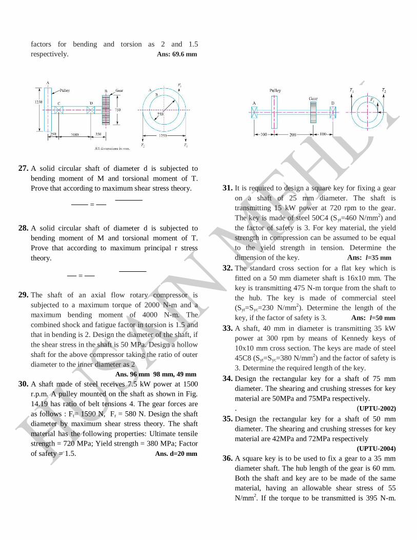
factors for bending and torsion as 2 and 1.5
respectively. Ans: 69.6 mm
27. A solid circular shaft of diameter d is subjected to
bending moment of M and torsional moment of T.
Prove that according to maximum shear stress theory.
=
28. A solid circular shaft of diameter d is subjected to
bending moment of M and torsional moment of T.
Prove that according to maximum principal r stress
theory.
=
29. The shaft of an axial flow rotary compressor is
subjected to a maximum torque of 2000 N-m and a
maximum bending moment of 4000 N-m. The
combined shock and fatigue factor in torsion is 1.5 and
that in bending is 2. Design the diameter of the shaft, if
the shear stress in the shaft is 50 MPa. Design a hollow
shaft for the above compressor taking the ratio of outer
diameter to the inner diameter as 2
Ans. 96 mm 98 mm, 49 mm
30. A shaft made of steel receives 7.5 kW power at 1500
r.p.m. A pulley mounted on the shaft as shown in Fig.
14.19 has ratio of belt tensions 4. The gear forces are
as follows : Ft= 1590 N, Fr = 580 N. Design the shaft
diameter by maximum shear stress theory. The shaft
material has the following properties: Ultimate tensile
strength = 720 MPa; Yield strength = 380 MPa; Factor
of safety = 1.5. Ans. d=20 mm
31. It is required to design a square key for fixing a gear
on a shaft of 25 mm diameter. The shaft is
transmitting 15 kW power at 720 rpm to the gear.
The key is made of steel 50C4 (Syt=460 N/mm2) and
the factor of safety is 3. For key material, the yield
strength in compression can be assumed to be equal
to the yield strength in tension. Determine the
dimension of the key. Ans: l=35 mm
32. The standard cross section for a flat key which is
fitted on a 50 mm diameter shaft is 16x10 mm. The
key is transmitting 475 N-m torque from the shaft to
the hub. The key is made of commercial steel
(Syt=Syc=230 N/mm2). Determine the length of the
key, if the factor of safety is 3. Ans: l=50 mm
33. A shaft, 40 mm in diameter is transmitting 35 kW
power at 300 rpm by means of Kennedy keys of
10x10 mm cross section. The keys are made of steel
45C8 (Syt=Syc=380 N/mm2) and the factor of safety is
3. Determine the required length of the key.
34. Design the rectangular key for a shaft of 75 mm
diameter. The shearing and crushing stresses for key
material are 50MPa and 75MPa respectively.
. (UPTU-2002)
35. Design the rectangular key for a shaft of 50 mm
diameter. The shearing and crushing stresses for key
material are 42MPa and 72MPa respectively
(UPTU-2004)
36. A square key is to be used to fix a gear to a 35 mm
diameter shaft. The hub length of the gear is 60 mm.
Both the shaft and key are to be made of the same
material, having an allowable shear stress of 55
N/mm2. If the torque to be transmitted is 395 N-m.
Determine the minimum dimension of key cross
section. Ans: b=6.84 mm, h=6.84 mm
37. Design a square key for fixing a gear on the shaft
having 25mm diameter. The gear rotates at 550 rpm
and transmits 12 kW power to the meshing gear. The
key is made of steel having yield stress in tension as
400 N/mm2. The yield stress in compression and
tension may be taken equal to each other. Assume
factor of safety is 2.5. (UPTU-2005) Ans:l=34mm
38. A standard splined connection 8x52x60 mm is used
for the gear and the shaft assembly of a gearbox. The
splines transmit 20 kW power at 300 rpm. The
dimension of the splines are as follow
Major diameter= 60 mm, Minor diameter = 52 mm
Number of splines = 8, Permissible normal pressure
on splines is 6.5 N/mm2. The coefficient of friction is
0.06. Calculate (i) Length of the hub (ii) The forced
require for shifting the gear.
Ans: l=110 mm, F= 1364.19 N
39. A steel shaft has a diameter of 25 mm. The shaft
rotates at a speed of 600 r.p.m. and transmits 30 kW
through a gear. The tensile and yield strength of the
material of shaft are 650 MPa and 353 MPa
respectively. Taking a factor of safety 3, select a
suitable key for the gear. Assume that the key and
shaft are made of the same material. Ans. l = 102 mm
40. A kennedy keys are used to transmit 30 kW power at
500 rpm from 40 mm diameter shaft to the hub. The
keys are made of steel 55C8 with yield strength of
400MPa and ultimate tensile strength of 700 MPa.
Ifnthe factor of safety required is 3 and over load
factor is 1.5, design the key. .
Ans: b=10 mm, h=10 mm l= 23 mm
41. Design a muff coupling which is used to connect two
steel shafts transmitting 40 kW at 350 rpm. The
material for the shaft and the key is plain carbon steel
for which allowable shear and crushing stresses may
be taken as 40 MPa and 80 MPa respectively. The
material for the muff is cast iron for which the
allowable shear stress may be assumed as 15 MPa.
42. Design of a muff coupling, which is used to connect
two steel shafts transmitting 25 kW power at 360
rpm. The shaft and key are made of plain carbon
steel 30C8 (Syt = Syc=400 N/mm2). The sleeve is
made of grey cast iron FG 200 (Sut=200 N/mm2).
The factor of safety for the shaft and key is 4. For
sleeve the fos is 6 based on ultimate strength.
43. Design a muff coupling to connect two mild steel
shafts to transmit 35 kW at 1440 r.p.m. The C.I
sleeve connects the shaft through two mild steel sunk
keys. The maximum torque transmitted is 25 %
greater than the average torque.Allowable shear
stress for C.I and mild steel are 15 N/mm2 and 65
N/mm2.and the allowable crushing stress for mild
steel= 160 N/mm2.
Ans: d=29 mm , D= 58 mm, L=102 mm, l=51 mm
44. Design a muff coupling to connect two shafts
transmitting 40 kW at 120 r.p.m. The permissible
shear and crushing stress for the shaft and key
material (mild steel) are 30 MPa and 80 MPa
respectively. The material of muff is cast iron with
permissible shear stress of 15 MPa. Assume that the
maximum torque transmitted is 25 per cent greater
than the mean torque.
45. It is required to design a split muff coupling to
transmit 50 kW power at 120 rpm. The shaft, key and
clamping bolts are made of plain carbon steel 30C8
(Syt =400n/mm2). The yield strength in compression
is 150% of tensile yield strength. The factor of safety
for the shaft, key and bolts is 5. The number of
clamping bolts is 8. The coefficient of friction
between halves and the shaft is 0.3.
46. Design a cast iron protective flange coupling to
connect two shafts in order to transmit 7.5 kW at 720
r.p.m. The following permissible stresses may be
used:
Permissible shear stress for shaft, bolt and key
material = 33 MPa, Permissible crushing stress for
bolt and key material = 60 MPa, Permissible shear
stress for the cast iron = 15 MPa
47. The shaft and flange of a marine engine are to be
designed for flange coupling in which the flange is
forged on the end of the shaft. The following
particulars are to considered in the design
Power of engine= 3MW
Speed of engine= 100 rpm
Permissible shear stress in bolt and shaft = 60 Mpa,
No of bolts used=8
Pitch circle diameter of bolts = 1.6 x diameter of
shaft. Find Diameter of shaft, diameter of bolts
Thickness of flange, diameter of flange.

48. Design a clamp coupling to connect two plain carbon
steel shafts to transmit 60 kW power at 500 r.p.m.
The C.I muff halves are clamped by four alloy steel
bolts. The key used has same material as that of the
shaft. The maximum torque transmitted is 20 %
greater than the average torque. Allowable shear
stress for shaft and key material are 55MPa and
allowable crushing stress for shaft and key material
=155 MPa.
Allowable crushing stress for C.I muff = 150 MPa,
Allowable Tensile stress for alloy steel bolts =130
MPa
49. Design a Cast Iron protective type flange coupling to
transmit 15 kW at 900 r.p.m from an electric motor
to a compressor. The service factor may be assumed
as 1.35. The following permissible stresses may be
used.
Shear stress for shaft, bolt and key = 40 MPa
Crushing stress for bolt and key = 80MPa
Shear stress for Cast Iron = 8 MPa
50. Two 35 mm shaft are connected by a flange
coupling. The flanges are fitted with 6 bolts on 125
mm bolt circle. The shaft transmits a torque of 800
N-m at 350 RPM. For the safe stresses mentioned
below, Calculate (i) diameter of bolts (ii0 thickness
of flanges (iii) Key dimension (iv) hub length and (v)
Power transmitted.
Safe shear stress for shaft material = 63 MPa
Safe stress for bolt material = 56 MPa
Safe stress for cast iron coupling = 10 MPa
Safe stress for key material = 46 MPa
51. Design a cast iron flange coupling for a mild steel
shaft transmitting 90 kW at 250 rpm. The allowable
shear stress in the shaft is 40 MPa and the angle of
twist is not to exceed 10 in a length of 20 diameters.
The allowable shear stress in the coupling bolts is 30
MPa.
52. A flexible coupling is used to transmit 15 kW power
at 100 rpm. There are six pins and their pitch circle
diameter is 200 mm. The effective length of the bush
(lb). The permissible shear and bending stress are 35
and 152 N/mm2
respectively Calculate the pin
diameter by shear consideration.
53. Design a bushed-pin type flexible coupling for
connecting a motor shaft to a pump shaft for the
following service conditions, Power to be transmitted
= 40 kW; speed of the motor shaft = 1000 r.p.m. ;
diameter of the motor shaft, = 50 mm; diameter of
the pump shaft = 45 mm. The bearing pressure in the
rubber bush and allowable stress in the pins are to be
limited to 0.45 N/mm2 and 25 MPa respectively
54. Design a Cast Iron protective type flange coupling to
connect two shaft of 36 mm diameter, transmitting at
720 r.p.m. The over load capacity 1.25 times the
average torque. The bolt and key are made of C20
steel and the flanges are made of Cast Iron. Assume
missing data suitable, if any U.P.T.U 2007-08)
55. Design a cast iron protective flange coupling to
connect two shafts in order to transmit 7.5 kW at 720
r.p.m. The following permissible stresses may be
used
Permissible shear stress for shaft, bolt and key
material = 33 MPa, Permissible crushing stress for
bolt and key material = 60 MPa, Permissible shear
stress for the cast iron = 15 MPa.

UNIT-IV
MEERUT INSTITUTE OF TECHNOLOGY MEERUT
B.Tech (Mechanical) (V semester)
Subject-Machine Design-1
Tutorial No-3
1. A compression coil spring made of an alloy steel is
having the following specifications :
Mean diameter of coil = 50 mm; Wire diameter = 5
mm; Number of active coils = 20. If this spring is
subjected to an axial load of 500 N; calculate the
maximum shear stress (neglect the curvature effect) to
which the spring material is subjected.
2. A helical spring is made from a wire of 6 mm
diameter and has outside diameter of 75 mm. If the
permissible shear stress is 350 MPa and modulus of
rigidity 84 kN/mm2, find the axial load which the
spring can carry and the deflection per active turn.
3. Design a spring for a balance to measure 0 to 1000 N
over a scale of length 80 mm. The spring is to be
enclosed in a casing of 25 mm diameter. The
approximate number of turns is 30. The modulus of
rigidity is 85 kN/mm2. Also calculate the maximum
shear stress induced.
4. A mechanism used in printing machinery consists of a
tension spring assembled with a preload of 30 N. The
wire diameter of spring is 2 mm with a spring index of
6. The spring has 18 active coils. The spring wire is
hard drawn and oil tempered having following
material properties:Design shear stress = 680 MPa,
Modulus of rigidity = 80 kN/mm2
Determine: 1. the initial torsional shear stress in the
wire; 2. spring rate; and 3. the force to cause the body
of the spring to its yield strength.
5. Design a helical compression spring for a maximum
load of 1000 N for a deflection of 25 mm using the
value of spring index as 5. The maximum permissible
shear stress for spring wire is 420 MPa and modulus
of rigidity is 84 kN/mm2.
6. Design a close coiled helical compression spring for a
service load ranging from 2250 N to 2750 N. The
axial deflection of the spring for the load range is 6
mm. Assume a spring index of 5. The
permissible shear stress intensity is 420 MPa and
modulus of rigidity, G = 84 kN/mm2.
Neglect the effect of stress concentration.
7. Design a valve spring of a petrol engine for the
following operating conditions
Spring load when the valve is open = 400 N
Spring load when the valve is closed = 250 N
Maximum inside diameter of spring = 25 mm
Length of the spring when the valve is open = 40
mm
Length of the spring when the valve is closed = 50
mm
Maximum permissible shear stress = 400 MPa
8. Design a helical spring for a spring loaded safety
valve (Ramsbottom safety valve) for the
following conditions :
Diameter of valve seat = 65 mm ; Operating
pressure = 0.7 N/mm2; Maximum pressure when
the valve blows off freely = 0.75 N/mm2;
Maximum lift of the valve when the pressure rises
from 0.7 to 0.75 N/mm2 = 3.5 mm ; Maximum
allowable stress = 550 MPa
Modulus of rigidity = 84 kN/mm2; Spring index =
6.
9. A safety valve of 60 mm diameter is to blow off at
a pressure of 1.2 N/mm2. It is held on its seat by a
close coiled helical spring. The maximum lift of
the valve is 10 mm. Design a suitable
compression spring of spring index 5 and
providing an initial compression of 35 mm. The
maximum shear stress in the material of the wire
is limited to 500 MPa. The modulus of rigidity for
the spring material is 80 kN/mm2.
Calculate: 1. Diameter of the spring wire, 2. Mean
coil diameter, 3. Number of active turns, and 4.
Pitch of the coil.
10. Its required to design a helical compression spring
subjected to a maximum force of 1250 N. The
deflection of the spring corresponding to the
maximum force should be approximately 30 mm.
The spring index can be taken as 6. The spring is
made of patented and cold drawn steel. The
ultimate tensile strength and modulus of rigidity
of the spring material are 1090 and 81370 N/mm2
respectively. The permissible shear stress for the
spring wire should be taken as 50 % of the
ultimate strength. Design the spring and calculate.
Wire diameter, mean coil diameter, Number of
active coil, free length of the spring, pitch of the
coil
11. It’s required to design a helical compression
spring for the mechanism. The axial force acting
on the spring is 300 N when the valve is open and
150 when the valve is closed. The length of the
spring is 30 mm when the valve is open and 35
mm when the valve is closed. The spring is made
of oil-hardened and tempered valve spring wire
and the ultimate tensile strength is 1370 N/mm2.
The permissible shear stress for spring wire
should be taken as 30% of the ultimate tensile
strength. The modulus of rigidity is 813770
N/mm2.Tyhe spring is fitted over a valve rod the
minimum inside diameter of the spring should be
20 mm Calculate:
Wire diameter, mean coil diameter, No of active
coil, total no of coil, free length of the spring,
pitch of the coil
(a) A helical tension spring is used in the spring
balance to measure the weights. One end of the
spring is attached to the rigid support while the
outer end, which is free, carries the weights to be
measured. The maximum weight attached to the
spring balance is 1500 N and the length of the
scale should be approximately 100 mm. The
spring index can be taken as 6. The spring is made
of oil hardened and tempered steel wire with
ultimate tensile strength opf 1360 N/mm2 and
modulus of rigidity of 81370 N/mm2. The
permissible shear stress in the spring wire should
be taken as 50 % of the ultimate tensile strength
Calculate : Wire diameter, mean coil diameter, no
of active coil, spring rate, actual spring rate
12. A helical compression spring made of oil
tempered carbon steel is subjected to a load which
varies from 400 N to 1000 N. The spring index is
6 and the design factor of safety is 1.25. If the
yield stress in shear is 770 MPa and endurance
stress in shear is 350 MPa, find: 1. Size of the
spring wire, 2. Diameters of the spring, 3. Number
of turns of the spring, and 4. free length of the
spring.
The compression of the spring at the maximum
load is 30 mm. The modulus of rigidity for the
spring material may be taken as 80 kN/mm2.
13. A helical compression spring of a cam-
mechanism is subjected to an initial preload of 50
N. The maximum operating force during the load
cycle is 150 N. The wire diameter is 3 mm, while
the mean coil diameter is 18 mm. The spring is
made of oil-hardened and tempered valve spring
wire of Grade-VW (Sut=1430 N/mm2). Determine
the FOS used in the diagram on the basis of
fluctuating stresses.
14. A closely coiled helical spring is made of 10 mm
diameter steel wire, the coil consisting of 10
complete turns with a mean diameter of 120 mm.
The spring carries an axial pull of
200 N. Determine the shear stress induced in the
spring neglecting the effect of stress
concentration. Determine also the deflection in the
spring, its stiffness and strain energy stored by it
if the modulus of rigidity of the material is 80
kN/mm2.