Sybex Autodesk Revit Architecture 2012 Essentials
374
-
Upload
anatolie-cuaresma-amper -
Category
Documents
-
view
64 -
download
5
description
new
Transcript of Sybex Autodesk Revit Architecture 2012 Essentials


Table of Contents
Cover
Title Page
Credits
Copyright
Publisher's Note
Dedication
Acknowledgments
About the Authors
IntroductionWho Should Read This BookWhat Is Covered in This BookThe Essentials SeriesContacting the Authors
Chapter 1: Introducing Revit and the User InterfaceUnderstanding the Revit InterfaceUnderstanding the Interface WorkflowUsing Common Modifying Tools
Chapter 2: Schematic DesignWorking from a SketchModeling In-Place MassesCreating Mass FloorsScheduling Mass FloorsUpdating the Massing Study
Chapter 3: Walls and Curtain WallsCreating Generic Walls

Creating Numerous Wall ConfigurationsModifying WallsCreating Curtain WallsModifying Curtain WallsUnderstanding Basic Wall Parts and Parameters
Chapter 4: Floors, Roofs, and CeilingsCreating FloorsLaying Out RoofsAdding Ceilings
Chapter 5: Stairs, Ramps, and RailingsCreating Numerous Stair ConfigurationsDesigning RampsBuilding Railings for Level and Sloped ConditionsWorking with Parts, Parameters, and Properties
Chapter 6: Adding FamiliesUnderstanding Different Family TypesLoading FamiliesPlacing Families
Chapter 7: Modifying FamiliesEditing View Display and Detail LevelChanging the Family CategoryModifying Family Geometry
Chapter 8: Groups and PhasingUsing GroupsUsing Phasing
Chapter 9: Rooms and Color Fill PlansTagging Spaces with Room TagsCreating Room KeysGenerating Color Fill Room Plans
Chapter 10: WorksharingEnabling WorksharingCreating Central and Local FilesAdding WorksetsAssigning Elements to Worksets

Saving to the Central FileCreating New ElementsUsing Workset Display FiltersUsing Worksharing to Work with ConsultantsUsing Guidelines for Worksharing
Chapter 11: Details and AnnotationsCreating DetailsAnnotating Your DetailsLegends
Chapter 12: Creating Drawing SetsCreating SchedulesPlacing Views on SheetsPrinting Documents
Chapter 13: Workflow and Other Revit EssentialsUnderstanding a BIM WorkflowModeling SiteDetailing in RevitPerforming Quality Control on Your Revit Model
Chapter 14: Tips, Tricks, and TroubleshootingOptimizing PerformanceUsing Best PracticesFixing File CorruptionLearning Tips and ShortcutsFinding Additional Resources
Appendix: Revit Certification
Index
Advertisement


Senior Acquisitions Editor: Willem KnibbeDevelopment Editor: Laurene SorensenTechnical Editor: Adam ThomasProduction Editor: Dassi ZeidelCopy Editor: Liz WelchEditorial Manager: Pete GaughanProduction Manager: Tim TateVice President and Executive Group Publisher: Richard SwadleyVice President and Publisher: Neil EddeBook Designer: Happenstance Type-O-RamaCompositor: Craig W. Johnson, Happenstance Type-O-RamaProofreader: Publication Services, Inc.Indexer: Ted LauxProject Coordinator, Cover: Katie CrockerCover Designer: Ryan SneedCover Image: _spacegroup

Copyright © 2011 by Wiley Publishing, Inc., Indianapolis, IndianaPublished simultaneously in Canada
ISBN: 978-1-118-01683-1
No part of this publication may be reproduced, stored in a retrieval system or transmitted in any form or by anymeans, electronic, mechanical, photocopying, recording, scanning or otherwise, except as permitted under
Sections 107 or 108 of the 1976 United States Copyright Act, without either the prior written permission of thePublisher, or authorization through payment of the appropriate per-copy fee to the Copyright Clearance Center,
222 Rosewood Drive, Danvers, MA 01923, (978) 750-8400, fax (978) 646-8600. Requests to the Publisher forpermission should be addressed to the Permissions Department, John Wiley & Sons, Inc., 111 River Street,
Hoboken, NJ 07030, (201) 748-6011, fax (201) 748-6008, or online at http://www.wiley.com/go/permissions.
Limit of Liability/Disclaimer of Warranty: The publisher and the author make no representations or warranties withrespect to the accuracy or completeness of the contents of this work and specifically disclaim all warranties,
including without limitation warranties of fitness for a particular purpose. No warranty may be created orextended by sales or promotional materials. The advice and strategies contained herein may not be suitable for
every situation. This work is sold with the understanding that the publisher is not engaged in rendering legal,accounting, or other professional services. If professional assistance is required, the services of a competent
professional person should be sought. Neither the publisher nor the author shall be liable for damages arisingherefrom. The fact that an organization or Web site is referred to in this work as a citation and/or a potentialsource of further information does not mean that the author or the publisher endorses the information the
organization or Web site may provide or recommendations it may make. Further, readers should be aware thatInternet Web sites listed in this work may have changed or disappeared between when this work was written and
when it is read.
For general information on our other products and services or to obtain technical support, please contact ourCustomer Care Department within the U.S. at (877) 762-2974, outside the U.S. at (317) 572-3993 or fax (317) 572-
4002.
Wiley also publishes its books in a variety of electronic formats. Some content that appears in print may not beavailable in electronic books.
Library of Congress Cataloging-in-Publication Data
Read, Phil, 1965– Autodesk Revit architecture essentials / Phil Read, Eddy Krygiel, James Vandezande. — 1st ed. p.cm. ISBN 978-1-118-01683-1 (pbk.) ISBN: 978-1-118-09732-8 (ebk.) ISBN: 978-1-118-09734-2 (ebk.) ISBN: 978-1-
118-09733-5 (ebk.) 1. Architectural drawing—Computer-aided design. 2. Architectural design—Data processing. 3.Autodesk Revit. I. Krygiel, Eddy, 1972- II. Vandezande, James, 1972- III. Title. NA2728.R39 2011
720.28’40285536—dc22 2011008887
TRADEMARKS: Wiley, the Wiley logo, and the Sybex logo are trademarks or registered trademarks of John Wiley &Sons, Inc. and/or its affiliates, in the United States and other countries, and may not be used without written
permission. Autodesk and Revit are registered trademarks of Autodesk, Inc. All other trademarks are the propertyof their respective owners. Wiley Publishing, Inc., is not associated with any product or vendor mentioned in this
book.
10 9 8 7 6 5 4 3 2 1

Dear Reader,Thank you for choosing Autodesk Revit Architecture 2012 Essentials. This book is part of a family of premium-quality Sybex books, all of which are written by outstanding authors who combine practical experience with a giftfor teaching.
Sybex was founded in 1976. More than 30 years later, we’re still committed to producing consistentlyexceptional books. With each of our titles, we’re working hard to set a new standard for the industry. From thepaper we print on, to the authors we work with, our goal is to bring you the best books available.
I hope you see all that reflected in these pages. I’d be very interested to hear your comments and get yourfeedback on how we’re doing. Feel free to let me know what you think about this or any other Sybex book bysending me an email at [email protected]. If you think you’ve found a technical error in this book, please visithttp://sybex.custhelp.com. Customer feedback is critical to our efforts at Sybex.
Best regards,
Neil Edde
Vice President and Publisher
Sybex, an Imprint of Wiley

To Justine:Thanks again for letting me work with Eddy and James. I promise not to blow all my earnings (like I didlast year) at the Mix Lounge in Vegas. I had no idea that a round of drinks would require a second mortgage.To Harrison:You’ve come a long way this year and you’re braver than you know. If you’ll go pick up the Legos
strewn all over your bedroom floor, I’ll make you a hot chocolate.To Millicent: The world is a tough place, but especially for a girl. Don’t trust everyone. Be honest, fair, strong, and
nice. But not too nice.To Jasper:You’re capable of the best Mr. Hankey, Conky, and Gumby impersonations I know. It’s seems silly, but it
means you’re capable of careful observation. Please keep up the great work at school and keep writing thosebooks.
To everyone else:Choose meaning over money. Don’t ever work for someone that you can’t deeply respect;especially when he’s sharply-dressed, sharply-elbowed, sharply-tongued, but not sharply-minded. You’re holding
back human progress.—Phil
Small monkeys. It’s good to have you around. You’ve seen that life is a lot of work and can be full of challenges. I’mproud of you for rising to meet them. It’s a hard thing to do.
—EddyFor my late father-in-law, Bill. You are missed every day and I know you would appreciate—but not necessarily
understand—these books we’re writing.—James

AcknowledgmentsAh, acknowledgments. While all the glory of writing a book is consumed by the authoring team, it takes so manymore people than the three of us to make this book happen. Just like building design, the process of writing andpublishing a book is truly a team sport and without the hard work, dedication, and willingness to put up with theauthoring team, this book would never have happened.
First, we’d like to thank all the fine folks at Autodesk Revit because without their excellent software wewouldn’t have a topic to write about. While it’s not possible to name them all, the work of the product designers,quality assurance team, and all the others doesn’t go unrecognized or unappreciated. Thank you, gals and guys, fortaking a tough job and doing it with a great attitude. Thank you to the development team for putting up with all ofour continued requests to make the product better.
Second, a big thanks to our technical team. They dot our i’s, cross our t’s, and berate us every time we turn insomething late. Their work and effort makes sure that we as authors can produce something that you the readercan actually comprehend. Thank you to Laurene, Liz, Dassi, and the rest of our editing team for translating oursentence fragments into the Queen’s English and not allowing us to use words like “this” and “they” and “it” asregular nouns; Pete, for keeping time; Adam, the guy who checks all of our Revit work; and our excellent supportteam at Sybex, who helped us develop and focus the content. As always, a special thanks to Willem Knibbe, for hiscontinually positive attitude in the face of deadlines, misspellings, and the general chaos that comes with workingon any of our projects.
—Phil Read, Eddy Krygiel, and James Vandenzande

About the Authors
Phil Read is the founder of Arch | Tech as well as one of the driving forces behind the original Revit software. He’salso a blogger, a speaker, and a popular presenter at Autodesk University. After working in both civil engineeringand architecture, he downloaded Revit version 1.0 (at the suggestion of an ArchiCAD reseller) and was hooked.Less than a year later, he began working for Revit Technology and then Autodesk as a project implementationspecialist, where he had the honor and pleasure of working with some of the most remarkable people and designfirms around the world. He’s a regular speaker, blogger, and Tweeter and relishes the role of change agent as longas it makes sound business sense. Phil holds degrees in communications and architecture, as well as a master’sdegree in architecture.

Eddy Krygiel is a senior project architect, a LEED Accredited Professional, and an Autodesk Authorized Author atHNTB Architects headquartered in Kansas City, Missouri. He has been using Revit since version 5.1 to completeprojects ranging from single-family residences and historic remodels to 1.12-million-square-foot office buildings.Eddy is responsible for implementing BIM at his firm and also consults for other architecture and contracting firmsaround the country looking to implement BIM. For the last four years, he has been teaching Revit to practicingarchitects and architectural students in the Kansas City area and has lectured around the nation on the use of BIMin the construction industry. Eddy also coauthored Mastering Autodesk Revit Architecture2011 with Phil Read andJames Vandezande (Sybex, 2010).
James Vandezande is a registered architect and a senior associate at HOK in New York City, where he is a memberof the firm-wide BIM leadership and is managing their buildingSMART initiatives. After graduating from the NewYork Institute of Technology in 1995, he worked in residential and small commercial architecture firms performingservices ranging from estimating to computer modeling to construction administration. In 1999, he landed at SOMand transformed his technology skills into a 10-year span as a digital design manager. In this capacity, he pioneeredthe implementation of BIM on such projects as One World Trade Center, a.k.a. Freedom Tower. James has beenusing Revit since version 3.1 and has lectured at many industry events, including Autodesk University, VisMastersConference, CMAA BIM Conference, McGraw_Hill Construction, and the AIANYS Convention. He is a cofounder and

president of the NYC Revit Users Group and is an adjunct lecturing professor at the NYU School for Continuing andProfessional Studies as well as the Polytechnic Institute of NYU.

Introduction
Welcome to AutodeskRevit Architecture 2012 Essentials, based on the Revit Architecture 2012 release.What you are holding in your hands is the first Revit book in a new series. When we authors first sat down to
learn Revit (eons ago), each of us was put into a room with a trainer, and over the course of four days, we clickedthrough all the buttons and functionality to learn the software. Once initiated, we walked away with someanswers, some questions, and a general understanding of what Revit does and how we could use it to leveragebuilding design, documentation, and construction.
Our aim with this book is to replicate that training experience. The book is divided into training “days” with theidea that each chapter should take you a couple of hours to complete and four chapters equal a full day of training.Once you’ve made it through the book, in the final two chapters we offer a half day’s worth of tips and tricks tohelp you leverage those skills on real projects.
When we sat down to plan this book, we looked to serve the needs of individuals who were fresh to Revit aswell as those who had taken training so long ago they needed a solid refresher. We hope you will find that ourefforts to meet that need were successful. We designed the book in a nonlinear fashion with the intention that thechapters would be freestanding, so the reader could take almost any chapter and learn its topics rather thanhaving to work through the book from beginning to end.
We wanted to write a book that is as much about architectural design and practice as it is about software.Architecture is a way of looking at the world and the methods that inspire creatively solving the problems of thebuilt world. The book follows real-life workflows and scenarios and is full of practical examples that explain how toleverage the tools within Revit. We hope you’ll agree that we’ve succeeded.
Who Should Read This Book
This book is written for architects, designers, students, and anyone else who needs their first exposure to Revit orhas had an initial introduction and wants a refresher on the program’s core features and functionality. It’s forarchitects (and those who’d like to be) of any generation—you don’t need to be a computer wizard to understandor appreciate the content. We’ve designed the book to follow real project workflows and processes to help makethe tools easy to follow, and the chapters are full of handy tips to make Revit easy to leverage. This book can alsobe used to help prepare for Autodesk’s Certified Associate and Certified Professional exams. For more informationon certification, please visit www.autodesk.com/certification.
What You Will LearnThis book is designed to help you grasp the basics of Revit using real-world examples and techniques you’ll use ineveryday design and documentation. We’ll explain the Revit interface and help you find the tools you need as wellas help you understand how the application is structured. From there we’ll show you how to create and modify theprimary components in a building design. We’ll show you how to take a preliminary model and add layers ofintelligence to help analyze and augment your designs. We’ll demonstrate how to create robust and accuratedocumentation, and then guide you through the construction process.
As you are already aware, BIM is more than just a change in software; it’s a change in architectural workflowand culture. To take full advantage of both BIM and Revit in your office structure, you’ll have to make somechanges to your practice. We’ve designed the book around an ideal, integrated workflow to aid in this transition.
Once you’ve mastered the content in each chapter, we include a section called “The Essentials and Beyond”where you can continue to hone your skills by taking on more challenging exercises.
What You NeedTo leverage the full capacity of this book, we highly recommend that you have a copy of Revit installed on acomputer strong enough to handle it. To download the trial version of Revit Architecture, go to

www.autodesk.com/revitarchitecture, where you’ll also find complete system requirements for running Revit.From a software standpoint, the exercises in this book are designed to be lightweight and not computationally
intensive. This way, you avoid long wait times to open and save files and perform certain tasks. That said, keep inmind that the Autodesk-recommended computer specs for Revit are far more than what you need to do theexercises in this book but are exactly what you need to work on an architectural project using Revit.
If you’re working from a 32-bit OS, you’ll need the following:Microsoft Windows 7 32-bit Enterprise, Ultimate, Professional, or Home Premium; Microsoft WindowsVista 32-bit (SP2 or later) Enterprise, Ultimate, Business, or Home Premium; or Microsoft Windows XP(SP2 or later) Professional or Home
Intel Pentium 4 or AMD Athlon dual core, 3.0 GHz (or higher) with SSE2 technology for MicrosoftWindows 7 32-bit or Microsoft Windows Vista 32-bit (SP2 or later). Intel Pentium 4 or AMD Athlon dualcore, 1.6 GHz (or higher) with SSE2 technology for Microsoft Windows XP (SP2 or later)
3 GB of RAM
5 GB of free disk space
1280 × 1024 monitor with true color
Display adapter capable of 24-bit color for basic graphics; 256 MB DirectX 9–capable graphics card withShader Model 3 for advanced graphics
Microsoft Internet Explorer 7.0 (or later)
Microsoft Mouse–compliant pointing device
Download or installation from DVD
Internet connectivity for license registration
If you’re working from a 64-bit version (which is preferred for project work due to how much RAM you canleverage), you’ll need the following:
Microsoft Windows 7 64-bit Enterprise, Ultimate, Professional, or Home Premium; Microsoft WindowsVista 64-bit (SP2 or later) Enterprise, Ultimate, Business, or Home Premium; or Microsoft Windows XPProfessional x64 edition (SP2 or later)
Intel Pentium 4 or AMD Athlon dual core, 3.0 GHz (or higher) with SSE2 technology for MicrosoftWindows 7 64-bit or Microsoft Windows Vista 64-bit (SP2 or later). Intel Pentium 4 or AMD Athlon dualcore, 1.6 GHz (or higher) with SSE2 technology for Microsoft Windows XP Professional x64 edition (SP2 orlater)
3 GB of RAM
5 GB of free disk space
1280 × 1024 monitor with true color
Display adapter capable of 24-bit color for basic graphics; 256 MB DirectX 9–capable graphics card withShader Model 3 for advanced graphics
Microsoft Internet Explorer 7.0 (or later)
Microsoft Mouse–compliant pointing device
Download or installation from DVD
Internet connectivity for license registration
What Is Covered in This Book

Revit is a building information modeling (BIM) application that has quickly emerged as the forerunner in the designindustry. Revit is as much a change in workflow (if you come from a 2D or CAD environment) as it is a change insoftware. In this book, we’ll focus on using real-world workflows and examples to guide you through learning thebasics of Revit 2012—the Essentials.
Autodesk Revit Architecture 2012 Essentials is organized to provide you with the knowledge needed to gainexperience in many different facets of the software. The book is broken down into 14 chapters, which representthe content you would cover if you were to attend a 3–4 day training class.
Day 1This section is designed to be an introduction to the software, the user interface, and the basic components thatyou will use every day.
Chapter 1, “Introducing Revit and the User Interface,” introduces to you the user interface and gets youacquainted with the tools and technology—the workflow—behind the software.
Chapter 2, “Schematic Design,” introduces you to situations that would happen on a real project; say, a designerhas given you a sketch and now you need to take this basic building design and model it.
Chapter 3, “Walls and Curtain Walls,” helps you build on that initial learning by establishing some of the basicbuilding blocks in architecture: walls.
Chapter 4, “Floors, Roofs, and Ceilings,” rounds out the first day of training by introducing you to the otherbasic building blocks: floors, roofs, and ceilings. By the end of the first four chapters, you will know how easy it is tocreate a building form; apply walls, floors, roofs, and ceilings to that form; and easily quantify how much space andarea are in your designs.
Day 2With the basic building forms established, you spend Day 2 of training augmenting that form with componentsthat help building form interact with reality. These components are what we interact with every day—things likestairs, windows, doors—and help establish the design.
Chapter 5, “Stairs, Ramps, and Railings,” begins by explaining the basics of stairs, ramps, and railings. These corecomponents are versatile and using them can be a bit tricky, so we’ll guide you through the process of creatingseveral types of stairs and railings.
Chapter 6, “Adding Families,” shows you how to add a core element to your project: families. You use familiesto create most of your content, and Revit by default comes with a robust supply.
Chapter 7, “Modifying Families,” shows you how to take these families, modify them, or create your own,making the library of your content limitless.
Finally, in Chapter 8, “Groups and Phasing,” you’ll learn techniques for taking families and repeating them in themodel in ways you can use to augment your design.
Day 3With two days of training under your belt, you’ll have most of the tools you need to create building designs inRevit. What we will focus on for the next four chapters is taking that design and documenting it so you can sharethe building design with owners, contractors, or anyone on your project team.
Chapter 9, “Rooms and Color Fill Plans,” shows you how to add room elements to your spaces, assigninformation to them, and create colorful diagrams based on space, department, or any other variable you need.
Chapter 10, “Worksharing,” discusses how to take your Revit file into a multiperson working environment.Worksharing allows several people within your office or project team to work on the same Revit filesimultaneously.
In Chapter 11, “Details and Annotations,” we focus on adding annotation to explain your designs. You’ll learnhow to add detail to your model in the form of dimensions, text, keynotes, and tags, and how to embellish your 3Dmodel with additional detailing.
Chapter 12, “Creating Drawing Sets,” shows you how to take all this information and place those drawings andviews onto sheets so they can be printed and distributed to your project stakeholders.
Day 4

The final two chapters in this book are designed to build on the skills you have just learned and give you someadditional resources to leverage your new talent.
Chapter 13, “Workflow and Other Revit Essentials,” provides the basics on how to take your office from a CADenvironment to one that works with BIM. This chapter explores tools for every level of the project team—from thenew staff to project managers. Understanding the process and workflow will be key to the success of your firstRevit project.
The final chapter, Chapter 14, “Tips, Tricks, and Troubleshooting,” is chock-full of useful tips and tricks, andyou’ll learn how to troubleshoot your Revit project.
The Essentials SeriesThe Essentials series from Sybex provides outstanding instruction for readers who are just beginning to developtheir professional skills. Every Essentials book includes these features:
Skill-based instruction with chapters organized around projects rather than abstract concepts or subjects
Suggestions for additional exercises at the end of each chapter, where you can practice and extend yourskills
Digital files (via download) so you can work through the project tutorials yourself. Please check the book’sweb page at www.sybex.com/go/revit2012essentials for the companion downloads.
Contacting the AuthorsWe welcome your feedback and comments. You can find the three of us on our blog,www.architecture-tech.com, or email us at [email protected]. We hope you enjoy thebook.

Chapter 1
Introducing Revit and the User Interface
After one decade in the architecture, engineering, and construction (AEC) space, Autodesk Revit Architecturecontinues to be unique in its holistic building information modeling (BIM) approach to design integration. Sure,there are other BIM-ish tools that allow you to design in 3D. And 10 years ago, 3D might have been adifferentiator, but today 3D is a commodity!
Revit provides the unique ability to design, manage, and document your project information from within asingle file, something that no other BIM tool will allow you to do. Because all your data resides in a single projectfile, you can work in virtually any view to edit your model—plan, section, elevation, 3D, sheets, details, and even aschedule. To begin the journey in learning Revit, we will help you become comfortable with the user interface andthe basic principles of a Revit project.
In this chapter, you learn the following skills:Understanding the Revit interface
Understanding the interface workflow
Using common modifying tools
Understanding the Revit InterfaceThe user interface (UI) of Revit is similar to other Autodesk products such as AutoCAD, Inventor, and 3ds Max. Youmight also notice that it is similar to other Windows-based applications such as Microsoft Word or Mindjet’sMindManager. All of these applications are based on the “ribbon” concept—where a set of toolbars are placed ontabs in a tab bar, or ribbon, and are contextually updated based on the content on which you’re working. We willcover the most critical aspects of the UI in this section, but we will not provide an exhaustive review of all toolbarsand commands. You will gain experience with the common tools as you read through the chapters and exercises inthis book.
Figure 1-1 shows the Revit Architecture 2012 UI. To illustrate some different project views, we’ve tiled fourdifferent view windows: Plan, Elevation, 3D, and Camera.
Figure 1-1: Revit 2011 User Interface
Let’s begin by examining just a few important parts of the UI. As you progress through the remaining chaptersin this book, you’ll gradually become more familiar with the other basic parts of the UI.
Properties PaletteThe Properties palette is a floating palette that can remain open while you work within the model. The palette canbe docked on either side of your screen, or it can be moved to a second monitor. You can open the Propertiespalette in one of three ways:
Clicking the Properties icon in the Properties panel of the Modify tab in the ribbon
Selecting Properties from the right-click context menu
Pressing Ctrl+1 on your keyboard, as you would in AutoCAD
As shown in Figure 1-2, the Properties palette contains the Type Selector at the top of the palette. When youare placing elements or swapping types of elements you’ve already placed in the model, the palette must be opento access the Type Selector.
Figure 1-2: The Properties palette allows you to set instance parameters for building elements and views.

When no elements are selected, the Properties palette displays the properties of the active view. If you need tochange settings for the current view, simply make the changes in the Properties palette and the view will beupdated. For views, you may not even need to use the Apply button to submit the changes.
Finally, you can also use the Properties palette as a filtering method for selected elements. When you select alarge number of disparate objects, the drop-down list below the Type Selector will display the total number ofselected elements. Open the list and you will see the elements listed per category, as shown in Figure 1-3. Selectone of the categories to modify the parameters for the respective elements. This is different from the Filter tool inthat the entire selection set is maintained, allowing you to perform multiple modifying actions without reselectingelements.
Figure 1-3: Use the Properties palette to filter selection sets.
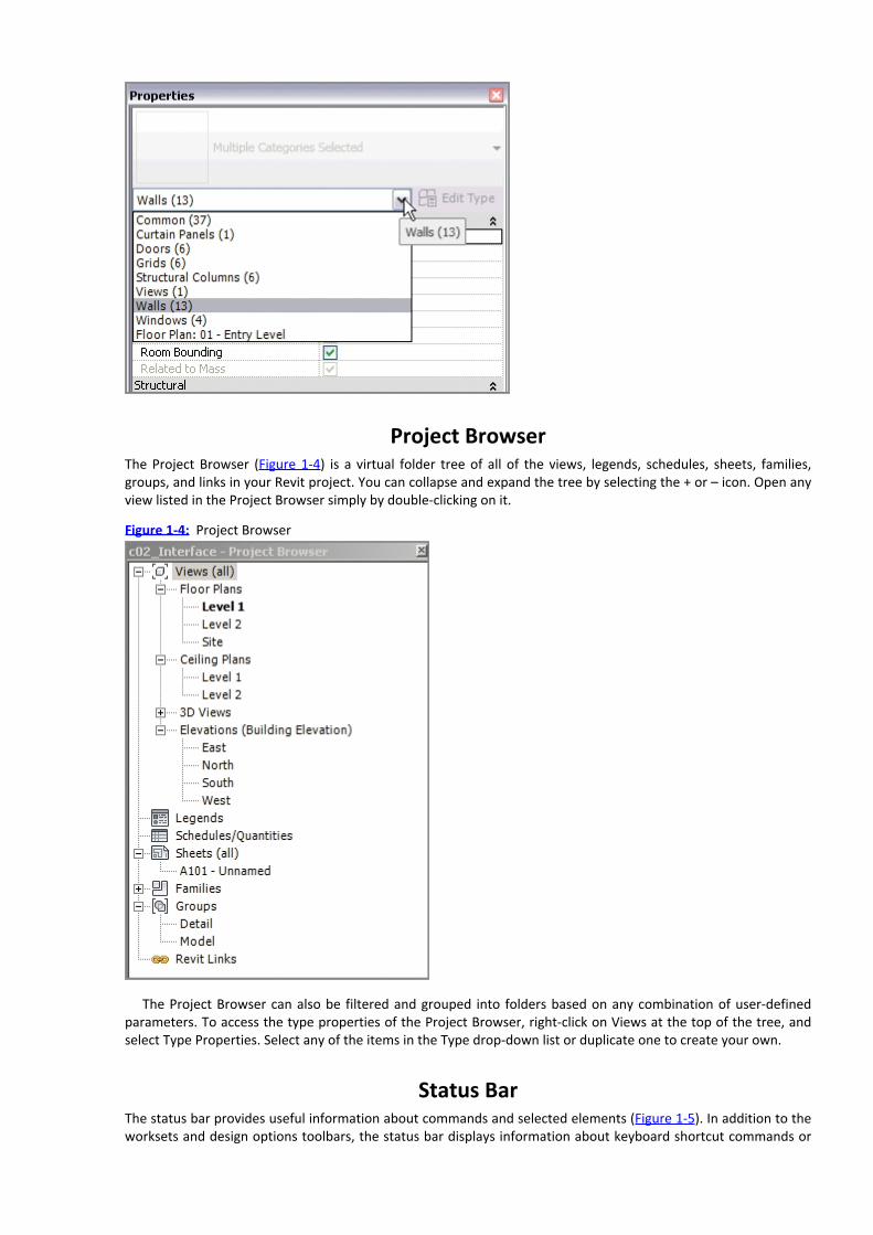
Project BrowserThe Project Browser (Figure 1-4) is a virtual folder tree of all of the views, legends, schedules, sheets, families,groups, and links in your Revit project. You can collapse and expand the tree by selecting the + or – icon. Open anyview listed in the Project Browser simply by double-clicking on it.
Figure 1-4: Project Browser
The Project Browser can also be filtered and grouped into folders based on any combination of user-definedparameters. To access the type properties of the Project Browser, right-click on Views at the top of the tree, andselect Type Properties. Select any of the items in the Type drop-down list or duplicate one to create your own.
Status BarThe status bar provides useful information about commands and selected elements (Figure 1-5). In addition to theworksets and design options toolbars, the status bar displays information about keyboard shortcut commands or

simply lists what object you have selected. It is also particularly useful for identifying when you are about to selecta chain of elements.
Figure 1-5: The status bar is located at the bottom of the Revit application window.
View Control Bar
The View Control Bar is at the bottom of every view and will have different icons depending on the type of view inwhich you are working (Figure 1-6).
Figure 1-6: The View Control Bar gives you quick access to commonly used view properties.
From left to right you have Scale, Detail Level, Visual Style, Sun Path (On/Off), Shadows (On/Off), RenderingShow/Hide (only in 3D Views), Crop On/Off, Show/Hide Crop, Lock 3D View (only in 3D views), TemporaryHide/Isolate, and Reveal Hidden Elements. Note that some of these buttons will access view properties you canalso set in the Properties palette.

ViewCubeAs one of several navigation aids in Revit, you’ll find the ViewCube in 3D views. You can orbit your model byclicking and dragging anywhere on the ViewCube. You can also click on any face, corner, or edge of the ViewCubeto orient your view.
Hovering over the ViewCube will reveal the Home option (the little “house” above the ViewCube), which willbring you back to your home view. Right-clicking the ViewCube will open a menu that will allow you to set, recall,and orient your view, as shown in Figure 1-7.
Figure 1-7: Right-click on the ViewCube to access more view orientation options.
Options BarThe Options Bar is a context-sensitive area that gives you feedback as you create and modify content. This is animportant UI feature when you are creating model content. For example, when you use the Wall command, theOptions Bar displays settings for the height, the location line, offset, and chain modeling options, as shown inFigure 1-8. Even when you place annotations, the Options Bar provides you with choices for leaders and otheradditional context.
Figure 1-8: The Options Bar provides immediate input of options related to a selected object or command.
Understanding the Interface WorkflowIn this section we will dive into the workflow of the Revit interface with some basic modeling exercises. Theselessons can be applied to just about every tool and function throughout the program.
Activating a command in Revit is a simple and repeatable process that takes you from a tool in the ribbon tooptions and properties and into the drawing window to begin placing an element. In the following exercise, youwill create a simple layout of walls using some critical components of the UI as well as a few common modifyingtools.

Creating a Simple LayoutBegin by downloading the file c01-Interface.rvt or c01-Interface-Metric.rvt from this book’s companion webpage: www.sybex.com/go/revit2012essentials. You can open a Revit project file by dragging it directly into theapplication or by using the Open command from the Application menu. You can even double-click on a Revit file,but be aware that if you have more than one version of Revit installed on your computer, the file will open in thelast version of Revit you used.
Once the project file is open, you will notice in the Project Browser that the active view is {3D}. This is thedefault 3D view, which you can always access by clicking the icon in the Quick Access toolbar (QAT) (which lookslike a little house). Note that the view name of the active view is always shown as bold in the Project Browser. Let’sbegin by placing some walls on some predetermined points in a plan view:
1. In the Project Browser, locate the Floor Plans category, expand it, and double-click on Level 1. This will openthe Level 1 floor plan view.2. From the ribbon, select the Home tab and click the Wall tool.3. In the Options Bar located just below the ribbon, change the Height to Level 2 and set Location Line to FinishFace: Exterior. Also make sure the Chain option is checked.4. At the top of the Properties palette, you will see the Type Selector. Click on it to change the wall type to BasicWall: Exterior - Brick on Mtl. Stud. Also find the parameter named Top Offset and change the value to 3´-0˝[1000 mm].Before you begin modeling, notice the Draw panel in the ribbon (Figure 1-9). You can choose from a variety of geometry options as you create 3D and 2D elements in the drawing area.
Figure 1-9:
Select geometry options from the Draw panel in the ribbon.
5. You are now ready to begin modeling wall segments. In the drawing area, click through each of the layoutmarkers from 1 through 6. Note how you can use automatic snapping to accurately locate the start and end ofeach segment. At point 3, place your mouse pointer near the middle of the circle to use the center snap point.6. After you click the last wall segment at point 6, press the Esc key once to stop adding new walls. You willnotice that the Wall command is still active and you can continue adding new walls if you choose. You can evenchange the wall type, options, and properties before continuing.7. Press the Esc key again to return to the Modify state. You can also click the Modify button at the left end ofthe ribbon.Your layout of walls should look like the image shown in Figure 1-10.
Figure 1-10: Your first layout of walls in a plan view
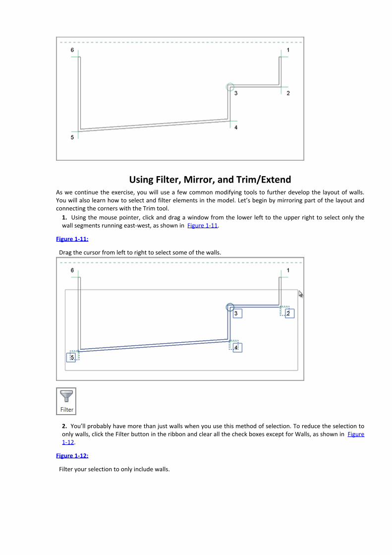
Using Filter, Mirror, and Trim/ExtendAs we continue the exercise, you will use a few common modifying tools to further develop the layout of walls.You will also learn how to select and filter elements in the model. Let’s begin by mirroring part of the layout andconnecting the corners with the Trim tool.
1. Using the mouse pointer, click and drag a window from the lower left to the upper right to select only thewall segments running east-west, as shown in Figure 1-11.
Figure 1-11:
Drag the cursor from left to right to select some of the walls.
2. You’ll probably have more than just walls when you use this method of selection. To reduce the selection toonly walls, click the Filter button in the ribbon and clear all the check boxes except for Walls, as shown in Figure1-12.
Figure 1-12:
Filter your selection to only include walls.

3. From the Modify tab in the ribbon, click the Mirror – Pick Axis tool and then click on the dashed linerepresenting the reference plane in the plan view. Mirrored copies of the selected walls will appear opposite thereference plane, as shown in Figure 1-13.
Figure 1-13:
Mirrored copies of the selected walls


Figure 1-16: Use the Switch Windows command to see what views you have activated.
Changing Element TypesNext you will change the properties for some of the elements you’ve already created using the Properties palette.You will also change some walls from one type to another. In the previous exercise, you created additional levels,thus increasing the overall desired height of your building. In the following steps, you will adjust the top constraintof the exterior walls and swap a few walls for a curtain wall type:
1. Activate the default 3D view. Remember, you can click the Default 3D View in the QAT or double-click the{3D} view in the Project Browser.2. Click the Close Hidden Views button in the QAT and then activate the South view under Elevations (BuildingElevation) in the Project Browser.3. From the View tab in the ribbon, locate the Windows panel and then click the Tile button. The two activeviews (default 3D view and South elevation) should now be seen side by side.4. In either view, find the Navigation bar, click the drop-down arrow under the Zoom icon, and then click ZoomAll To Fit, as shown in Figure 1-17.
Figure 1-17:
Use Zoom All To Fit when you are using tiled windows.

.
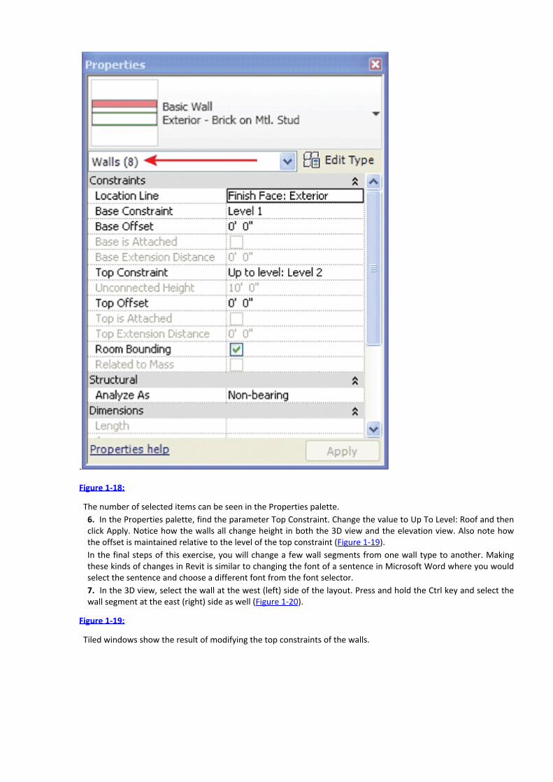
Figure 1-18:
The number of selected items can be seen in the Properties palette.6. In the Properties palette, find the parameter Top Constraint. Change the value to Up To Level: Roof and thenclick Apply. Notice how the walls all change height in both the 3D view and the elevation view. Also note howthe offset is maintained relative to the level of the top constraint (Figure 1-19).In the final steps of this exercise, you will change a few wall segments from one wall type to another. Makingthese kinds of changes in Revit is similar to changing the font of a sentence in Microsoft Word where you wouldselect the sentence and choose a different font from the font selector.7. In the 3D view, select the wall at the west (left) side of the layout. Press and hold the Ctrl key and select thewall segment at the east (right) side as well (Figure 1-20).
Figure 1-19:
Tiled windows show the result of modifying the top constraints of the walls.

Figure 1-20:
Use the Ctrl key to manually select multiple items in your model.
8. At the top of the Properties palette is the Type Selector. Click it to open the list of available wall types withinthe project. Scroll down to the bottom of the list and select the type Curtain Wall: Exterior Glazing. You may geta warning when you make this change; if so, just select Unjoin Walls or whatever the recommended action is.Your result should look like the image in Figure 1-21.9. Remember to save your project file before continuing with subsequent lessons.
Figure 1-21: Wall segments have been changed to a different type.


8. In the plan view, click on each of the two interior walls you just created. You will see one dimension appearbetween the two walls, but the command is still active. Keep going to the next step.9. Hover the mouse pointer over one of the two exterior walls and you will notice that the centerline of the wallis the default reference. Press the Tab key until you see the inside face of the wall highlight, as shown in Figure1-24, and then click to add the dimension. Repeat this process for the exterior wall on the other side.
Figure 1-24:
Use the Tab key to toggle between wall references before you place a dimension.


Now try moving each of the exterior walls again. Observe how the constrained dimensions are preserving yourintent to keep the outer rooms at their defined dimension.
Aligning ElementsIn the following exercise, you will use dimensions to precisely place two more walls. You will then learn how to usethe Align tool to preserve a dimensional relationship between two model elements. The Align tool can be used injust about any situation in Revit and is therefore a valuable addition to your common toolbox.
To begin this exercise, you will use temporary dimensions to place a wall segment. Elements in Revit can beinitially placed in specific places using temporary dimensions or you can place them and then modify theirpositions using temporary or permanent dimensions as you learned in the previous exercise.
Before you begin this exercise, you will need to adjust the settings for temporary dimensions. Switch to theManage tab in the ribbon and click Other Settings and then Temporary Dimensions. Change the setting for Walls toFaces and the setting for Doors And Windows to Openings, as shown in Figure 1-26.
Figure 1-26: Modifying the settings for temporary dimensions

1. Add a wall using Interior - Partition Type A2 to the main layout area. Continue to use the Finish Face: Interiorlocation line option; however, use a temporary dimension to place each wall exactly 8´-0˝ [2.5 m] from thenearest wall intersection, as shown in Figure 1-27. Repeat this process for the opposite side.2. Press the Esc key or click the Modify button in the ribbon to exit the Wall command. Select one of the wallsyou created in step 1. You will see a string of temporary dimensions appear. Drag the grip on the far left of thedimension string so that it aligns with the outside edge of the other wall, as shown in Figure 1-28.3. Click the dimension icon just below the length shown in the temporary dimension to convert it into a regulardimension string. Select the dimension string and click the lock symbol to establish a constraint, as shown inFigure 1-29.
4. Zoom out so you can see both new interior wall segments. From the Modify tab in the ribbon, select the Aligntool.
Figure 1-27:
Place an interior wall using temporary dimensions.
Figure 1-28:
Adjust references of temporary dimensions by dragging grips.

Figure 1-29:
A temporary dimension has been converted and locked.
5. As illustrated in Figure 1-30, click the face of the wall that has been constrained in step 3 (a), click thecorresponding face of the other new wall (b), and then click the lock to constrain the alignment (c).
Figure 1-30: Use the Align tool to create an alignment and constrain the relationship.
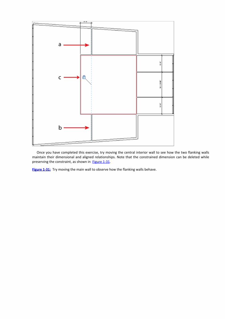
Once you have completed this exercise, try moving the central interior wall to see how the two flanking wallsmaintain their dimensional and aligned relationships. Note that the constrained dimension can be deleted whilepreserving the constraint, as shown in Figure 1-31.
Figure 1-31: Try moving the main wall to observe how the flanking walls behave.


5. Use the Component tool again and choose Chair-Desk from the Type Selector. Press the spacebar until thechair orients properly with the desk (Figure 1-33).
Figure 1-33:
Place a chair with the desk in the main space.
6. Repeat this process for the desk in the east wing, but add two additional chairs on the opposite side of thedesk (Figure 1-34).7. Select the desk and chair in the main space and click the Create Group command in the Create panel of thecontextual ribbon. Name the group Desk-Chair-1.
Figure 1-34:
Place three chairs with the desk in the east wing.

8. Repeat the process for the desk and chairs in the east wing. Name the group Desk-Chair-3.9. Select the group Desk-Chair-3 and click the Copy command in the ribbon. Set the Constrain and Multipleoptions in the Options Bar and begin to copy the group into each of the three spaces in the east wing.10. With the Copy command still active, uncheck the Constrain option and place a copy of the group in thespace at the north side of the layout. Your copied furniture should look like the image in Figure 1-35.
Figure 1-35:
Create copies of the group with multiple chairs.


In this exercise, you created a simple group of furniture elements. Groups can be a powerful tool for managingrepeatable layouts within a design, but they can cause adverse performance if they are abused. There are far toomany opinions and best practices for using groups to be listed in this chapter; however, there are just a fewimportant tips to be aware of. Groups should be kept as simple as possible and they shouldn’t be mirrored. Youshould also avoid putting hosted elements in groups—but you’ll learn more about these types of elementsthroughout this book.
Aligned Copying and Group EditingOne powerful and essential tool in Revit is the copy-to-clipboard command known as Paste Aligned. As you’ve seenthroughout this chapter so far, this is yet another tool that can be used on just about any kind of model or draftingelement. In the following exercises, you will take the interior content you developed in the previous exercises andreplicate it on other levels within the building.
1. Activate the Level 1 Furniture floor plan from the Project Browser.2. Select all the interior walls, doors, and furniture seen in the floor plan.3. In the Clipboard panel of the ribbon, click the Copy To Clipboard tool. You could also press Ctrl+C on yourkeyboard.
4. Also in the Clipboard panel of the ribbon, click the Paste drop-down button and select Aligned To SelectedViews. You will be prompted with a dialog box to select levels to which the selected content will be copied inexactly the same position (Figure 1-38). Select Level 2 and Level 3 using the Ctrl key to make multiple selections.
Figure 1-38:
Use Paste Aligned To Selected Levels to create duplicate floor layouts.

5. Activate the view 3D Cutaway from the Project Browser to view the results of the aligned copying (Figure 1-39).
Figure 1-39: The 3D Cutaway view uses a section box to display the inside of a building.
Now that you have created many copies of the furniture group on several levels, you can harness the power ofthe group by making changes to the group and observing how the overall design is updated.
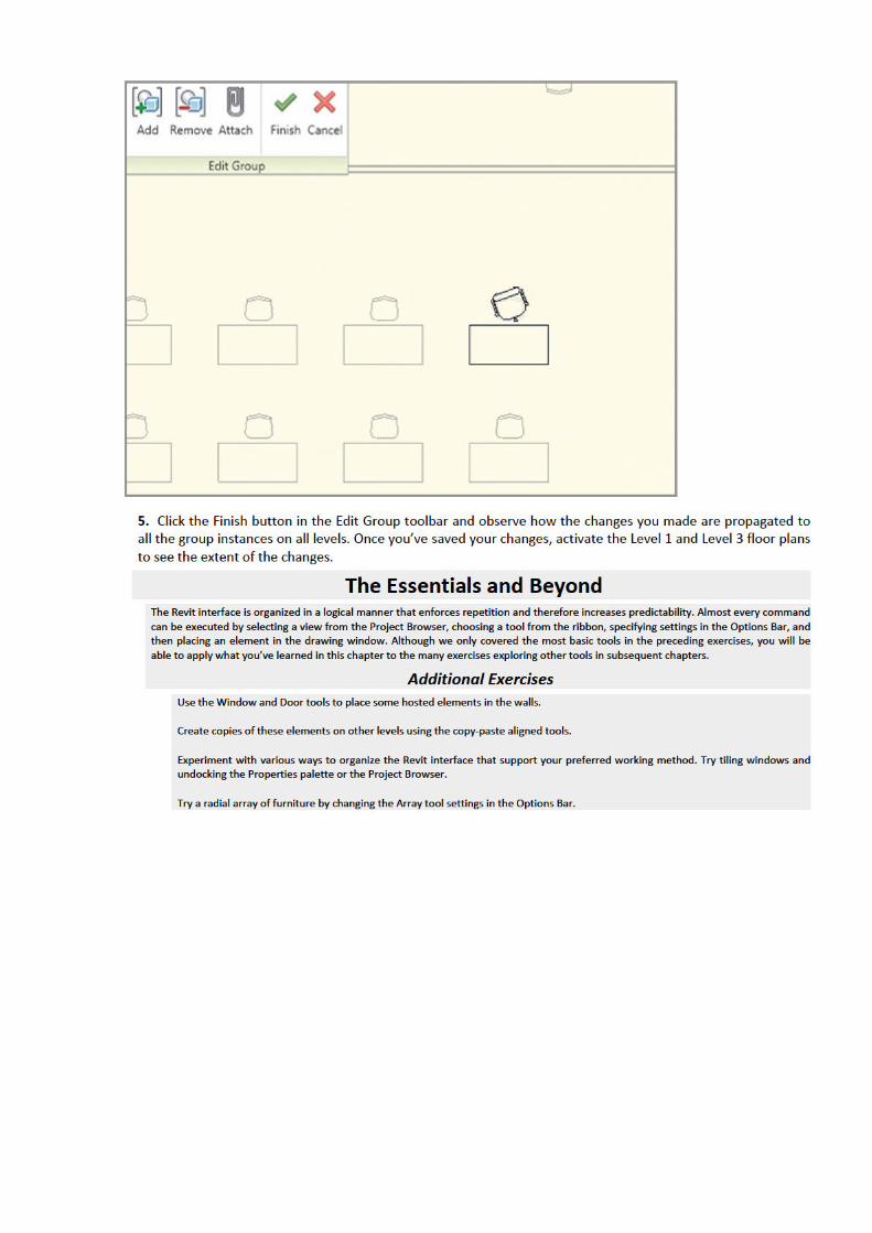
1. Activate the Level 2 floor plan from the Project Browser.2. Select one of the Desk-Chair-1 furniture groups in the main space. Click on the Edit Group button from thecontextual ribbon. The view window will turn a light shade of yellow and a temporary toolbar will appear at theupper left of the view area.3. Select the chair in the group and from the Type Selector, change it to Chair-Executive.4. Rotate the chair 20 degrees using the Rotate tool (Figure 1-40).
Figure 1-40:
The view window will enter a temporary group editing mode.

Chapter 2
Schematic Design
Design inspiration comes from many sources. For example, some designers still like to sketch by hand, but thesketch needs to align with the building program. Many of our modern sketches now happen digitally to make thistransition easier.
When you begin migrating your conceptual design from the sketch to the computer, don’t start with buildingelements (walls, floors, and so forth). Start with more primal elements, a process called massing in Revit, to makesure your program is correct. Once you’ve confirmed that the mass contains the required building program, you’llbe able to start placing building elements with far more confidence. While massing is capable of much morecomplex form-making than you’ll see in this chapter, it’s a great starting point for learning Revit.
In this chapter, you learn the following skills:Working from a sketch
Modeling in-place masses
Creating mass floors
Scheduling mass floors
Updating the massing study
Working from a SketchSketches can be a great source for starting design massing in Revit. In certain cases, hand drawings can be scannedfrom physical pen and paper drawings. In some design workflows, sketching directly within a computer applicationis becoming increasingly common. To support this digital workflow, in 2010 Autodesk released a tool for Apple’siPad called SketchBook Pro (Figure 2-1) that allows you to sketch directly on the iPad or iPhone using a stylus oreven your finger.
The sketch in Figure 2-1 was created on the iPad, but this example will work for any scanned sketchdesign—even one on tracing paper. In our sample scenario for this chapter, the designer has created sketches of aproposed building form and would like you to import each of the orientations into Revit and use them as contextfor a quick massing study. The building program allows a maximum building height of about 800′ [244 m] andrequires a gross area of 3.5 million square feet [325,000 square meters].
Figure 2-1: A hand sketch from Autodesk’s SketchBook Pro for the iPad.

Importing Background ImagesLet’s look at how you can combine the design’s sketches with Revit’s massing tools to help deliver preliminaryfeedback about the design. When you open Revit for the first time, you’ll find yourself at the Revit home screen.This screen keeps a graphic history of the recent projects and families that you’ve worked on.
1. From the home screen, select New to open the default Revit template. Open the South elevation by double-clicking on it in the Project Browser.2. On the Insert tab, select the Import panel and click the Image tool (Figure 2-2).
Figure 2-2:
Select the Image tool on the Import panel.
3. Select the Ch 2 Massing Sketch.png file from the Chapter 2 folder on this book’s web page(www.sybex.com/go/revit2012essentials). Once you select the image, you will be put back in the Southelevation view.4. You’ll see a large, empty-looking box with an X through it. This is the Image Placement tool. Place the image
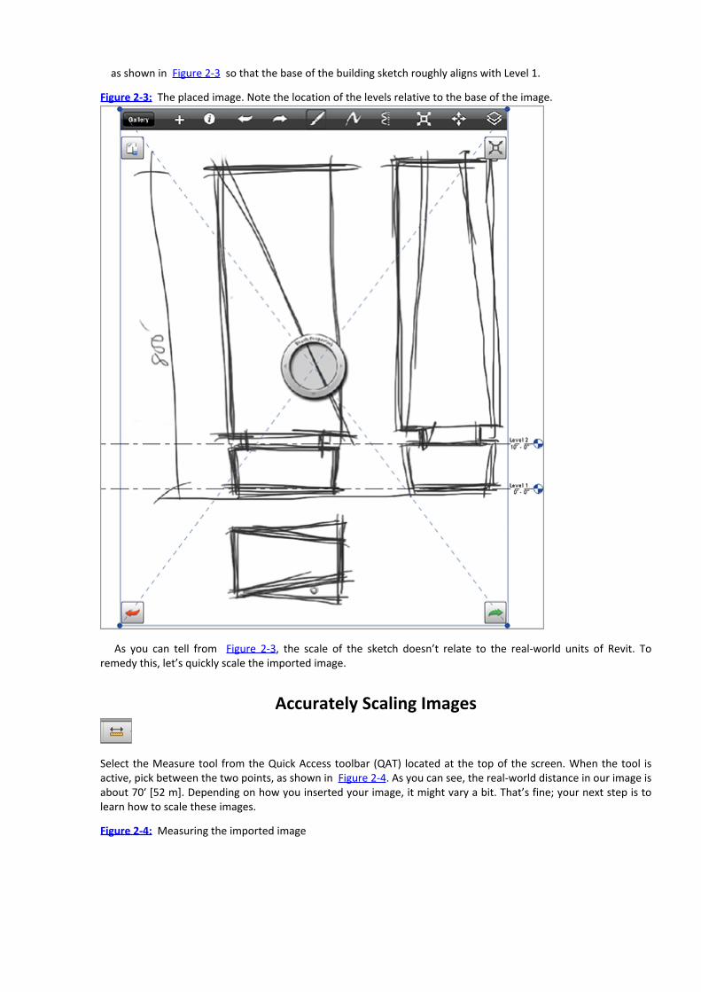
as shown in Figure 2-3 so that the base of the building sketch roughly aligns with Level 1.
Figure 2-3: The placed image. Note the location of the levels relative to the base of the image.
As you can tell from Figure 2-3, the scale of the sketch doesn’t relate to the real-world units of Revit. Toremedy this, let’s quickly scale the imported image.
Accurately Scaling Images
Select the Measure tool from the Quick Access toolbar (QAT) located at the top of the screen. When the tool isactive, pick between the two points, as shown in Figure 2-4. As you can see, the real-world distance in our image isabout 70′ [52 m]. Depending on how you inserted your image, it might vary a bit. That’s fine; your next step is tolearn how to scale these images.
Figure 2-4: Measuring the imported image

You know the desired distance is 800′ [243 m] between the two points you just measured. One way to changethe image size is to select the image and manually enlarge it by dragging the corner grips until the distance iscorrect—and in many cases this might be close enough. However, we’ll show you a more precise method:
1. Select the image and look at the Properties palette on the left. Notice the current dimension for the Heightfield is 85′-4″ [26 m] in our example. To modify the image size, you need to increase the Height value with regardto the desired and actual dimensions.2. To determine this value, first divide 800′ [243 m] (the desired height) by 70′ [52 m] (the measured distance).Then multiply the result by 85′-4″ [26 m] (the current height) and enter the quotient. Using Revit’s built-indatabase functionality, you can do the math right in the Properties palette!3. Type the formula shown in Figure 2-5. Be sure to add the = sign at the beginning of the formula. The heightof the image will increase significantly (over 975′ [2,735 m]). But now the imported image has proportionallyincreased the correct amount.
Figure 2-5:
A formula for adjusting the image height

4. Move the lower edge of the sketch to align with Level 1 again. Also, increase the scale of the view to 1″ = 30′-0″ [1:500] so that the level’s symbols are more visible (Figure 2-6).
Figure 2-6: The resulting image
Reference Planes and Levels
Reference planes are one of the most useful tools in Revit. The planes are represented in Revit as green dashedlines, and they will display in any view perpendicular to the reference plane. They don’t print in your drawingsheets, but they are handy as a tool to align elements that are coplanar. Think of them as levels and grids exceptthat you don’t need to show them on your sheets.

In our example, it’s important to use reference planes as guides to help you create the masses in other viewssince the image you imported will only be visible in the imported view. Reference planes are like guidelines thatcan be seen across many views. They will be extremely helpful when you line up the sketch in the South elevationand then in the North elevation or plan view.
To begin, click the Home tab, and on the Work Plane panel, select the Ref Plane tool. Next, create referencelines that correspond with the edges of the sketch by tracing over the edges. The dimensions in Figure 2-7 havebeen added as a reference for you. You don’t need to add dimensions—just add the reference planes as shown.We also adjusted the scale of the view so that the level symbols are easy to read.
Figure 2-7: Dimensioned reference planes
Now let’s add some levels to the sketch that will be useful for determining the limit of the three masses you’lladd:
1. Move Level 2 to 20′-0″ [6 m] by selecting the 10′-0″ [3 m] value and typing in the new elevation, as shown inFigure 2-8.
Figure 2-8:
Enter the new elevation.


1. First, select Level 10. The Modify | Levels menu becomes active. Select the Array tool from the Modify panel.2. Since Level 10 is at an elevation of 150′-0″ [45 m], you need to create an array with the options shown inFigure 2-10. These options can be adjusted in the Options Bar below the context menu. The Options Bar willdynamically change based on the tools you have selected.
Figure 2-10:
Array options
3. Select the second Move To option in the Options Bar, and pick a location that is directly 12′-0″ [3.6 m] aboveLevel 10. Change the value of the Number field to 55. Once you click to place the 5th level, the additional 55levels at 12′-0″ [3.6 m] will be created, and your final level (Level 64) appears at 798′-0″ [243 m]. That’s prettyclose to our goal of 800′-0″ [243 m]!The final step before creating the mass is to add the sketched image to the East elevation and Level 1, which
you’ll do in a moment. Before you add the final elevation, let’s discuss a change management tip. No design workis ever static (it’s always changing), so it’s important to understand how to keep up with those iterations in Revit.In this case, you want to be able to manage the ability to update the images in case the designer gives you somenew sketches. Keep in mind that if the image changes in size or shape, you’d probably want all the images tochange as well. Here is where groups come in handy. A group is similar to what in AutoCAD is called a block or inMicroStation, a cell. Groups are collections of Revit elements that you want to move or repeat as a single unit, butyou want to have the ability to subdivide or “ungroup” if needed. Let’s explore a few uses for groups, and then addour final elevation.
Creating and Placing GroupsIn this exercise, we’re going to create a group and explore potential uses for the Group command.
1. Select the image you inserted earlier in the South elevation and then select the Group tool from the Createpanel on the Modify tab.2. When the Create Detail Group dialog opens, name the group Massing Sketch 1, as shown in Figure 2-11, andclick OK.
Figure 2-11:
Create Detail Group dialog
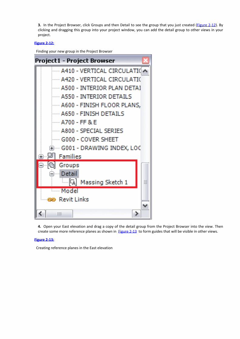
3. In the Project Browser, click Groups and then Detail to see the group that you just created (Figure 2-12). Byclicking and dragging this group into your project window, you can add the detail group to other views in yourproject.
Figure 2-12:
Finding your new group in the Project Browser
4. Open your East elevation and drag a copy of the detail group from the Project Browser into the view. Thencreate some more reference planes as shown in Figure 2-13 to form guides that will be visible in other views.
Figure 2-13:
Creating reference planes in the East elevation

5. Drag a final copy of the detail group into your Level 1 view and center it within the South and East viewreference planes you created, as shown in Figure 2-14. Now you have the three views necessary for massing thebuilding.
Figure 2-14: Reference planes in the Level 1 view
Images and GroupsEach image that you import in Revit can only be seen in the view that it is placed within. In other words, an image placed in the Southelevation view will only be seen in that elevation view. In our example, we’re trying to assemble a 3D context for modeling geometry and

we’ll need to place the image in multiple views.
When you change the scale or proportion of one of the images, you’ll likely want to change all of them. Groups are used in Revit tomaintain relationships between collections of elements. When one group changes, all the groups change. This is very helpful forcollections of components that are compiled into units, such as like furniture layouts, hotel rooms, and apartment types.
Modeling In-Place MassesNow that you’ve imported the designer’s sketch and drawn the appropriate reference planes for added context,you can start creating the massing elements that will represent the building. You will do so using a tool called In-Place Masses. Consider masses as families in Revit that are created directly within the project. This tool allows youto model within the context of the project you’re actively working in.
Modeling the Base MassTo model the base mass, follow these steps:
1. Open your Level 1 floor plan view by double-clicking Level 1 in the Project Browser.
2. Select the Massing & Site tab on the ribbon and select the In-Place Mass tool.3. Revit displays a dialog telling you that it has now enabled the Show Mass option in the current view. ClickClose.4. The Name dialog appears. For this exercise, let’s use the default name, which is Mass 1 (see Figure 2-15).Click OK.
Figure 2-15:
Use the default mass name.
5. Now you’re in a special, in-place editor for creating masses in Revit. You’ll notice the menu options havechanged. Select the Rectangle tool.6. Using the Rectangle tool, sketch lines as shown in Figure 2-16. These lines should cover the form and beplaced along the reference planes you created earlier.
Figure 2-16:

Sketching a rectangular form
7. Select the lines and then select the Create Form tool from the Form panel.The results aren’t immediately obvious since you’re looking at a solid form in plan. To view the results from
another angle, return to the South elevation. Select the top of the form by clicking on it and use the grip arrows, asshown in Figure 2-17, to increase the form’s height until it aligns with Level 8. The edge of the forms will “stick” tothe level when you’re close and snap itself into place.
Figure 2-17: Increasing the height of the mass

Sketching MassesThe type of mass that you’re creating in this exercise is called an extrusion. There are many other configurations of masses, includingblends, sweeps, swept blends, and revolves. After you’ve created the initial mass, it’s possible to edit the form dramatically; you can evenuse voids to “carve” away at your initial form.
We don’t have the space to go into that level of complexity. But modeling more complex masses is something that you’ll likely want tolearn. Check out http://au.autodesk.com/?nd=class_listing.
Modeling the Middle MassThe next step is to model the middle mass form:
1. Return to the Level 1 plan view. Set the view to Wireframe, as shown in Figure 2-18 (so you can see throughthe mass you’ve just created). The Wireframe button is located in the View Control Bar at the bottom of thescreen.
Figure 2-18:
Setting View to Wireframe
2. Using the same workflow, sketch another rectangle as shown in Figure 2-19. Then select the rectangle andclick Create Form.
Figure 2-19:
Sketching the second rectangle

3. Once again, open the South elevation and use the grip arrows to move the second mass form so that theupper face aligns with Level 10 and the lower face aligns with Level 8, as shown in Figure 2-20. Don’t forget thatyou can set the view display to Wireframe if you need to see through the first mass to the second mass. Changesto one view won’t be reflected in every view.
Figure 2-20: Second mass in place
Modeling the Upper MassThe process of creating the third (and uppermost) mass starts the same as for the first two masses:
1. Return to Level 1 and create a rectangular sketch that connects the outermost reference planes, as shown in

Figure 2-21. Then select the lines and click Create Solid. Extend the upper and lower faces to align with Levels 64and 10, respectively.
Figure 2-21:
Creating the third sketch and mass form
2. Return to the South elevation and use the grip arrows to extend the top and bottom of the form.You could continue to work in 2D views, but it’ll be more helpful if you can see what you’re doing in 3D.
Working in 3D
Select the Default 3D View icon from the QAT. Doing so allows you to see the working mass more completely, asshown in Figure 2-22.
Figure 2-22: Default 3D view of the completed mass

You likely noticed from the imported sketches that the East façade of the mass should taper in elevation. Thebase and the top are different widths. By adding an edge to each face (both North and South), you’ll be able toadjust the upper form appropriately:
1. First, hover over the South face of the upper form and select the face by clicking on it. Doing so activates the
Add Edge tool on the Form Element panel.2. The Add Edge tool divides one plane on the mass by adding another edge that can be adjusted independentlyof the other edges. Add the edge at the front, lower corner of the upper mass, as shown in Figure 2-23.
Figure 2-23:
Adding the South face edge

3. Rotate the model to expose the North face. Do so by selecting the intersection of the ViewCube between theright, back, and top sides. The model will spin around, zoom extents, and center.4. Select the North or Right face to add an edge.5. Open the East elevation from the Project Browser. Use the grip arrows to adjust this face of the upper mass.As you hover your mouse pointer over the intersection, a vertex control will appear as a purple dot at the upper-right corner where you added a face (Figure 2-24).
Figure 2-24:
Selecting the vertex

6. Select this control and then use the grip arrows to move it to the intersection of the uppermost level andright reference plane. Next, do the same thing to the west side of the mass. The result will resemble Figure 2-25.
Figure 2-25:
Resulting South elevation and 3D view
7. Your mass is nearly complete, but first you need to join all the mass geometry together. From the Modify tabselect the Join tool on the Modify panel. Then select the lower and middle forms to join them. Repeat thisprocess for the middle and upper forms.8. Now that the forms have been joined together, select the Finish Mass tool from the In-Place Editor panel. It’s
the big, green check mark , meaning you’re done!Congratulations! You’ve just created your first massing study!
Joining Masses

Each mass is an independent object. Masses can even be scheduled independently from each other. You’ll find this functionality helpfulfor creating separate masses for programming purposes (such as convention space or meeting rooms). But be careful if you haveoverlapping masses.
If overlapping masses are not properly joined, Revit will create overlapping mass floors and your schedules will be incorrect. Furthermore,if you create real floors from the mass floors, the floors will overlap rather than create a single element.
Creating Mass Floors
Floor area faces are incredibly useful for getting a sense of the gross area of a building mass at any intersectinglevel. Furthermore, the results can be quickly and easily scheduled. Any changes to the massing study will updatethe schedules and all views in real time.
Select the completed mass and then click the Mass Floors tool in the Model panel. You’ll be given the option toselect all the levels in your project. You want to select them all, but rather than select them one at a time, selectLevel 1, and then scroll down. While pressing Shift, select Level 64. Now all of the levels are selected. Check anybox, and all of the boxes will automatically be checked. Click OK.
Your mass has now been bisected with mass floors (faces with no geometry), as shown in Figure 2-26.
Figure 2-26: The mass has been bisected with mass floors.
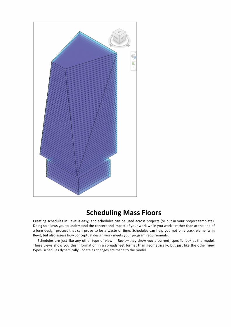
Scheduling Mass FloorsCreating schedules in Revit is easy, and schedules can be used across projects (or put in your project template).Doing so allows you to understand the context and impact of your work while you work—rather than at the end ofa long design process that can prove to be a waste of time. Schedules can help you not only track elements inRevit, but also assess how conceptual design work meets your program requirements.
Schedules are just like any other type of view in Revit—they show you a current, specific look at the model.These views show you this information in a spreadsheet format than geometrically, but just like the other viewtypes, schedules dynamically update as changes are made to the model.

1. To begin the mass schedule, select the View tab from the ribbon. Then select the Schedules drop-down in theCreate panel. Click Schedules/Quantities.2. In the New Schedule dialog, select the Mass Floor option from the column on the left and leave the otherfields (Schedule Name and Phase) at their default values. Click OK.3. The next dialog contains a series of tabs. We’ll step through some of these to set up the schedule. On theFields tab, select level and floor areas by double-clicking them in the Available Fields list or by selecting a fieldand then clicking the Add button (Figure 2-27).
Figure 2-27:
Selecting the scheduled fields
4. On the Sorting/Grouping tab, change Sort By to Level. Also, choose Title, Count, And Totals from the drop-down next to Grand Totals, as shown in Figure 2-28.
Figure 2-28:
Selecting the Sorting/Grouping fields

5. On the Formatting tab, select the Floor Area field and then click the Calculate Totals option (Figure 2-29).Click OK.
Figure 2-29: Calculating totals
Figure 2-30 shows the resulting schedule. With a total of 63 floor levels, Revit is calculating a gross floor area ofjust over 4.5 million square feet [418,000 square meters].
Figure 2-30: Gross floor area

Unfortunately, we know from the program (at the beginning of this section) that the gross floor area needs tobe closer to 3.5 million square feet [325,000 square meters]. So let’s get back to that massing study and tweak theform to get it closer to the program’s results.
Updating the Massing Study
Begin by selecting the mass in the default 3D view and then clicking the Edit In-Place button on theModel panel. Doing so returns you to In-Place editing mode and allows you to have specific control over massgeometry.
You’re going to modify the east and west faces, moving each face 40′-0″ [12 m] to the center. Hovering overand selecting the east face of the upper mass displays a temporary dimension and the shape handles.
Select this dimension and, by clicking on the blue text, change the value from 300′-0″ [91 m] to 260′-0″ [80 m].Do the same for the middle and lower east faces. Now the gross floor area is closer to 3.25 million square feet(Figure 2-31), or about 302,000 square meters. We quickly and easily got the program where it needs to be.
Figure 2-31: Resulting gross floor area
We also need the program to be closer to 3.5 million square feet. A quick discussion with the designer revealsthat the base of the building is meant to hold important meeting and conference spaces. So you’ll extend theeastern base of the building to 300′ [91 m]. Once again, you do so by repeating the previous steps of selecting themass and returning to In-Place editing mode. Make certain that the base element is 300′ deep and then finish themass.
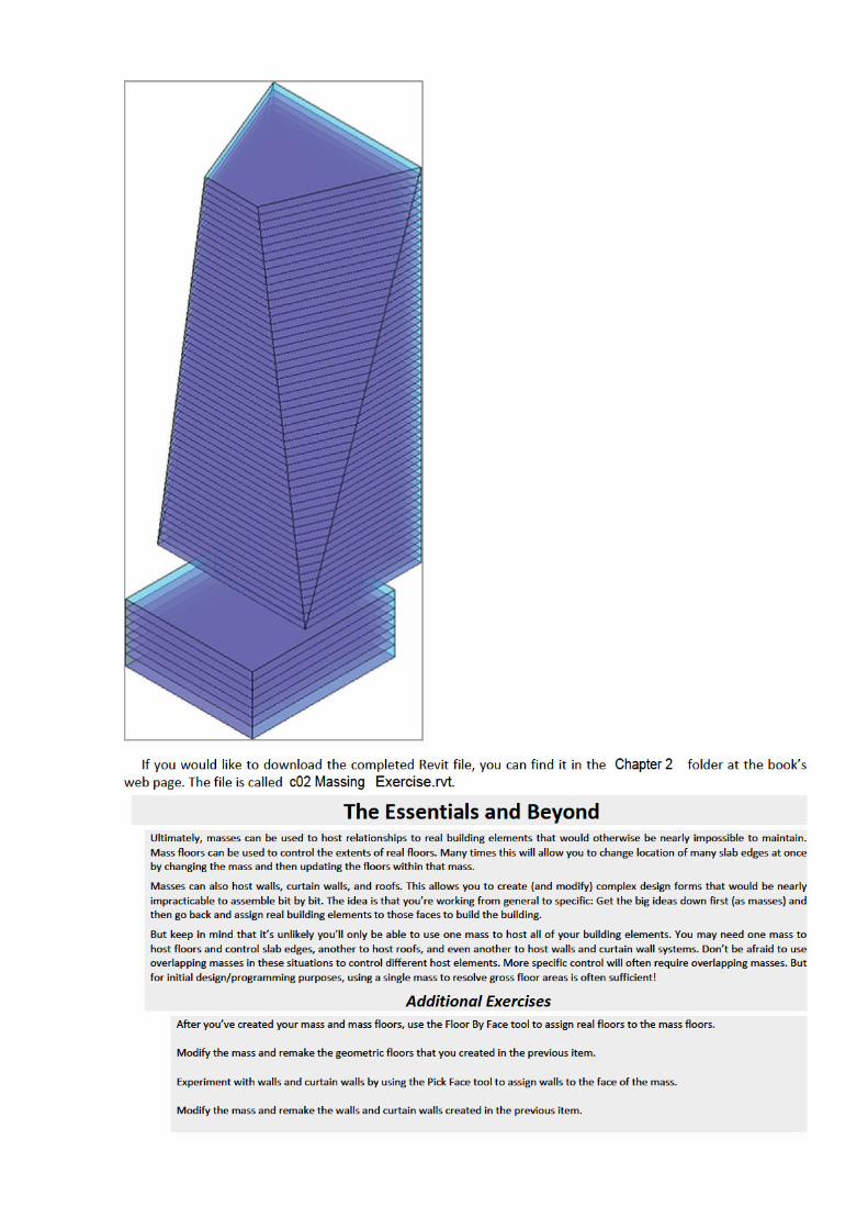
Once this is done, the mass will look like Figure 2-32 and the gross floor area will be within the requiredprogram.
Figure 2-32: Final mass


Chapter 3
Walls and Curtain Walls
Walls in Revit can range a great deal in complexity. Early in the design process, walls and curtain walls can be moregeneric, vertical containers for space and function. But they can also be associated to masses in order to createincredibly complex shapes. As the design progresses, these generic walls and curtain walls can be swapped out formore specific vertically compound walls that indicate a range of materials as well as geometric sweeps and reveals.
In this chapter, you learn the following skills:Creating generic walls
Creating numerous wall configurations
Modifying walls
Creating curtain walls
Modifying curtain walls
Understanding basic wall parts and parameters
Creating Generic Walls
The first thing you want to do is understand how walls generally work and how you should modify them. Thechallenge is that during the design process there’s a lot that is not known (and probably can’t be known), whichcan lead to a lot of unnecessary confusion.
Revit uses a system of “Generic” walls that in most cases are not made of anything specific. They’re simplyabout the right thickness for the eventual condition. We recommend using these generic walls during the designprocess, and then swapping out these walls for more specific geometry later.
By default, the generic walls that have no specific structure are visually identical to walls that contain structureand finish layers. So it’s a great idea to make your design walls visually unique. This way, you’ll know what has tobe swapped out for more specificity later. And there are also some more advantages, such as giving your wallstransparency, that will help you quickly and easily visualize your design.
Let’s start by giving our generic walls a material assignment that can be used to distinguish them from morespecific wall types:
1. Go to the Home tab on the ribbon and select the Wall tool from the Build panel (Figure 3-1).
Figure 3-1:
Choose the Wall tool from the Build panel.
2. Now select Basic Wall Generic – 6˝ from the Properties menu (Figure 3-2) and sketch a west to east 20´-0˝(6.1 meters) portion of a wall. Don’t worry about any of the other settings for the time being. When you’re done,

go to the Default 3D View, from the Quick Access toolbar.
Figure 3-2:
Generic 6˝ wall from the menu and the wall in 3D
3. Select the wall and look at the properties. As you can see, there are a lot of values that apply to this particularpiece of wall. You can change its height, constraints, and many other values (we’ll get to most of them later). Fornow, let’s create a unique Type property for the wall’s material.4. Select the Edit Type option to open the Type Properties dialog box for the wall. To the right of the Structurelabel, click the Edit button. Select the <By Category> field, as shown in Figure 3-3.
Figure 3-3:
Select the Material Field.

5. Rather than create a material from scratch, let’s duplicate something that is close and then modify it. Scrolldown to the Default Wall material and then select the Duplicate option, as shown in Figure 3-4. Name theMaterial Generic Material and then click OK.
Figure 3-4:
Duplicating the wall material

6. Once you click OK, you will have a new material that you’ll be able to replace with other rendered and shadedvalues. Click the Replace button on the Render Appearance tab. On the Graphics tab, set the Shading value asshown on the left in Figure 3-5 by selecting the colored panel. Then select the Appearance tab in Figure 3-5 toassign a newly rendered material, as shown on the right in Figure 3-5. This material will be useful for any designelements (floors, ceilings, roofs, etc.) that are used to resolve the design intent when you’re not sure of thespecific design content.
Figure 3-5: Assigning the material
Designing Generic ElementsGeneric elements play a large part in Revit. When you’re creating your design, it’s not practical to use lines to represent ideas when youcan use content. But if you select something that’s too specific, you might become frustrated. A design that is too specific too early hasthe tendency to be “exactly wrong.”

“Design” elements and materials help convey the intent of your design with the added benefit of scheduling, so that the data about aproject is headed in the right direction without distracting anyone. They’ll help you emphasize “where” something is as well as some of“what” something is without getting into the detail of how it’s supposed to be assembled—until the time is right. Most of the frustrationin design comes from working specifically to generally, rather than the other way around. Design elements will help you avoid this trap.
The Shading and Rendered values don’t need to be the same. And in this case it’s really helpful if they’re not.When you use a white rendered material, you’ll get a neutral, matte rendering. But changing the Shading value willhelp you quickly distinguish between design intent and more specific resolved elements.
Click OK in all open dialog boxes until you’re back in the project environment. Set the view to Shaded WithEdges, as shown in Figure 3-6. Now you can quickly and easily tell your design elements from more specificselections.
Figure 3-6: Shaded With Edges
Creating Numerous Wall ConfigurationsNow let’s return to our Level 1 Floor Plan view and start creating a number of wall configurations. Pick the Wallcommand and you’ll notice that a number of configurations are available for creating walls (Figure 3-7).
Figure 3-7: Configuring walls
Sketching WallsWalls are sketched by drawing the various configurations. These options are available in Figure 3-8. Take amoment to go through each of the sketching and editing options so that you become familiar with theresults—particularly when drawing curved sections. The option to keep concentric is very important. Creatingtangent arcs takes particular care as well.
Figure 3-8: Wall configurations that can be sketched
Creating Elliptical WallsSince creating elliptical walls often comes up, we’ll get it out of the way and give you the answer in two parts. First, elliptical walls can’t besketched as a singular element. And second (more importantly), they can be created via other workarounds (like creating elliptical masses

and then picking the face of the mass to create elliptical walls).
The reason is that documenting the elliptical walls is difficult. There’s no center to locate, and the arcs are continually changing in plan.
So what’s a better way? Create the ellipse from a series of tangent arcs. Doing so will give you an approximation that is indistinguishablefrom an actual ellipse, and you’ll be able to guide a more exact construction.
And if you don’t know how to create an ellipse, just look around the office and ask for the person who used to design buildings withpencils. And after they tell you how, expect them to walk away snickering a bit at your expense.
Picking WallsYou can also create walls by picking lines. This approach is helpful if you have a CAD file that needs to be convertedto a BIM model, or if the designer has created a single line design in another tool (like SketchUp) and expects youto use the exported results to start from in Revit.
Start by creating a few model lines. Click the Model Line tool, as shown in Figure 3-9.
Figure 3-9: Picking model lines
Now draw a series of lines that resembles Figure 3-10. Now that you have a few lines in your project, you cancreate walls using these lines with the Pick Lines tool (highlighted in Figure 3-10).
Figure 3-10: Sketching model lines
You have two options. You can create walls by picking single lines one at a time. Or, you can hover over one lineand then press and release the Tab key. Doing so will highlight the chain of lines, as shown in Figure 3-11. Nowyou can pick the entire chain of lines to create a chain of walls.
Figure 3-11: Selecting a chain of lines

Hosting Elements in WallsWalls can host elements that are meant to create openings. As long as the walls exist, the elements they arehosting will exist as well. Doors and windows are two common hosted elements.
Placing a door in a wall is very easy and can be done in plan, elevation, or 3D views. In this exercise, you’ll placedoors from the Level 1 view. You’ll use the very first wall that you created at the beginning of this chapter. Fromthe Home tab, select the Door tool from the Build panel.
As you hover over walls, you’ll notice that you’re able to place doors in them. You’re also shown temporarydimensions that will help you place the door closer to its correct location. Go ahead and place two doors as shownin Figure 3-12. Notice that by default Revit will tag the door number for you.
Figure 3-12: Hosting Doors in Walls
As mentioned earlier, walls can also host windows. Start by selecting the Window tool from the Home tab onthe Build panel. Hover over the same wall and place a window as shown. As with any hosted elements, you’ll onlybe able to place them within a host (Figure 3-13).
Figure 3-13: Hosted window
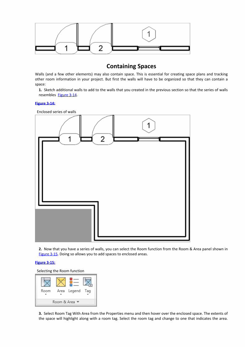
Containing SpacesWalls (and a few other elements) may also contain space. This is essential for creating space plans and trackingother room information in your project. But first the walls will have to be organized so that they can contain aspace:
1. Sketch additional walls to add to the walls that you created in the previous section so that the series of wallsresembles Figure 3-14.
Figure 3-14:
Enclosed series of walls
2. Now that you have a series of walls, you can select the Room function from the Room & Area panel shown inFigure 3-15. Doing so allows you to add spaces to enclosed areas.
Figure 3-15:
Selecting the Room function
3. Select Room Tag With Area from the Properties menu and then hover over the enclosed space. The extents ofthe space will highlight along with a room tag. Select the room tag and change to one that indicates the area.

Then place the room and tag in the space (Figure 3-16).
Figure 3-16: Placing the room and room tag
What’s really great is that when the shape of the room changes, the area reported will immediately update toreflect the new space. Return to the Wall tool and use the Fillet Arc tool to fillet the lower-right intersection of thewalls. The room area will update as shown in Figure 3-17.
Figure 3-17: Room tag with updated area
Modifying WallsNow that you’ve created a few wall configurations, it’s important to understand how you can modify them.Sometimes this is done simply by selecting the wall and dragging a wall end or a shape handle to a new position. In

other cases, you want to be more exact and assign a specific value.Your approach depends on where you are in the design process. Just remember that you can update design
decisions and all your views, schedules, tagging, and so forth will update. So don’t get too concerned with beingtoo “exact” early in your design.
Start by sketching another straight segment of a wall, but this time as you draw the wall, type 40 (or 12meters). Depending on the default units, typing 40 will create a 40´ segment. Notice that you didn’t have toindicate the units “feet.” If you wanted to indicate “inches,” you’d only have to put a space between the first andsecond values. So 40´-6˝ can easily be entered as “40(space)6”.
To modify the length, select the wall. You’ll notice there are three options (Figure 3-18). You can type in a newvalue by selecting the temporary dimension, or you can simply drag either wall end to a new location.
Figure 3-18: Modifying the wall length
Now let’s go to the Default 3D View and look at some other options. The highlighted areas of Figure 3-19 arecalled shape handles. You can press and drag them to adjust the top and bottom locations of a wall. As you dragthe shape handle, the new location will be shown, whereas the existing location will be “ghosted” until you releasethe Shape Handle.
Figure 3-19: Wall shape handles

Instance ParametersIn many cases you’ll want to enter more exact values, or just have more specific control over a particular wallinstance. You can do this through the Instance Parameters menu (Figure 3-20). Select the wall and look at theproperties.
Location Line The location line is the “origin” of the wall, and if you swap one wall for another, the location linewill be maintained.
Base Constraint The base constraint is the bottom of the wall. Be careful! Deleting a constraint (in this caseLevel 1) also deletes what is associated to the constraint!
Base Offset The base offset is the value above or below the base constraint. So if you wanted a wall associatedto Level 1 but 3´-0˝ (1 meter) below, the value would be –3´–0˝.
Base Is Attached The Base Is Attached value will allow you to automatically attach the bottom of a wall to thetop of another wall, floor or roof.
Figure 3-20: Instance Parameters
Unconnected Height The Unconnected Height value is the height of the wall. You can type in a specific value,but in this case the value is pretty irregular because we’ve manually dragged the shape handle to the newposition.
Top Constraint The top constraint is presently shown as Unconnected. It can also be associated to Level 2, forexample. This way, the wall will move vertically up or down if the level moves. For example, setting the TopConstraint to Level 2, the Unconnected Height will immediately reset to that value.
Top Is Attached Top Is Attached allows you to automatically attach the top of the wall to the underside of awall, floor, or roof.
Room Bounding The last value you should be aware of is the Room Bounding option. Walls often are meant tocontain space and remain space aware. This is what happened when you placed the Room tag in a previousexercise. But if you have a situation where you don’t want walls to define a space, you can deselect this optionand the Room tag will ignore the walls.
Editing and Resetting ProfilesOf course not all walls are rectilinear in elevation. For these situations you can edit the profile of a wall. Note thatyou’ll only be able to edit the profile of a straight wall, not curved walls.
1. Start by selecting the 40´ wall and selecting Edit Profile from the Modify | Walls tab (Figure 3-21).

Figure 3-21:
Editing the profile for walls
2. From a South Elevation view, create the internal sketch as shown in Figure 3-22. Don’t worry aboutdimensioning the sketch. We’re just showing the dimensions for reference. Now delete the top line and fillet thetwo side sketch lines (Figure 3-22). Note that the reference lines indicating the extents of the original wall willremain.
Figure 3-22:
Adding new sketch lines
3. When you are done, click Finish Sketch Mode.
Attaching and Detaching Top and Base
We’ve previously attached the top of a wall to a roof. But walls can also be attached to the top or bottom of otherwalls. Let’s do this with a copy of the wall from the edit elevation example.
1. Copy the wall off to the side, select it, and then click Edit Profile. Modify the exterior sketch as shown inFigure 3-23. Don’t forget to trim and delete unnecessary sketch lines. Then finish the sketch.
Figure 3-23:
Edited wall profile

2. Now return to your Level 1 Plan View and sketch another wall right on top of the same location of the wallyou just edited. But in this case, use a Generic 12˝ wall. The walls will overlap and that’s okay.3. Select the lower 12˝ wall and then click Attach Top/Base (Figure 3-24). Now select the wall with the profilethat we just edited. This will attach the top of the 12˝ wall to the underside of the other wall, as shown on theright side of the figure.The great thing about this technique is that relationships between the two walls are maintained if you edit the
elevation profile of the upper wall. Performing these steps is a lot faster than having to edit the elevation profile ofboth walls!
Figure 3-24: Attach Top/Base
Resetting ProfilesOne last thing about editing wall profiles: If you need to remove the edited condition, don’t reenter Edit Profilemode and manually remove the sketches. Select the wall and click Reset Profile in the Mode panel on the Modify |Walls tab. Doing so will reset the extents and remove any interior sketches.
Cutting Openings

Openings can be cut in both straight and curved walls. But the command tends to get used in curved walls becauseyou already have the option to edit the elevation profile in straight walls. And when you cut an opening, you’re notable to sketch beyond the extents of the wall boundary or create shapes that are not rectilinear. Here are the stepsto create a rectilinear opening in a curved wall:
1. Start by creating a curved wall segment and then go to your Default 3D View and select the wall.2. The Wall Opening option will then appear on the Modify | Walls tab, as shown in Figure 3-25 on the left.Select this command and then hover over the wall; you’ll be prompted to create a rectilinear opening, as shownon Figure 3-25 on the right. To delete an opening, hover over the opening, select it, and then press the Deletekey.
Figure 3-25: Creating wall openings
Splitting WallsSometimes after you’ve created walls you realize that you don’t need an inner segment—or you need to change asegment to another wall type. Having to delete and re-create walls would be tedious. Revit allows you to splitwalls, effectively breaking them up into smaller pieces. This can be done along both horizontally and vertical edgesof either curved or straight walls.
Let’s experiment with this technique by creating a plan configuration of walls, as shown in Figure 3-26. Thedimensions are shown for reference.
Figure 3-26: Configuration of walls
In this case the section of wall between the two parallel walls is not needed. But rather than delete the wall andcreate three new walls, let’s split the wall twice and delete the inner wall.
1. Select the Split Element command from the Modify tab.2. Hover over the location of the wall that you intend to split. You’ll be prompted with a reference line thathelps indicate to you which wall you’re splitting. Split the wall twice at each intersection.

3. Delete the inner segment. Your wall will now resemble Figure 3-27.
Figure 3-27: Using the Split Element command
Swapping Walls
Swapping walls keeps you from having to delete them and start over. You can do the same thing when changingwalls from one type to another. Doing so is as easy as selecting a wall and then selecting the new type from theProperties palette.
1. We’ll use the wall from the section, “Attaching and Detaching Top and Base.” Select the lower wall and thenassociate it to a new type.2. Change the lower wall to Generic – 12˝ Masonry. Once you select the new wall type, the result will resemblethe wall in Figure 3-28. Note that the patterns of the individual CMU courses are shown on the new wall’ssurface.
Figure 3-28: Selecting a new wall type
Creating Curtain Walls
Curtain walls are created in much the same way as regular walls: by selecting the type of curtain wall and then

sketching the desired shape. But the available parameters are rather different. Let’s start by creating a 40´-0˝ (12meter) section, using Curtain Wall 1 as the wall type.
Grid LinesBefore adding mullions, we need to add grid lines to the curtain panel to which the mullions can associate.
1. Select the Curtain Grid tool from the Build panel (Figure 3-29).
Figure 3-29:
Curtain Grid tool
2. As you hover over the edge of the curtain panel, Revit will prompt you with a dashed line that indicates thegrid location. Also notice that the grid location gets kind of “sticky” at the 1⁄2 and 1⁄3 lengths along the edge3. Place two evenly spaced grid lines in the horizon and vertical edge. When you’re finished, the curtain panelwill look like Figure 3-30.
Figure 3-30: Completed grid lines

Adding Mullions
Now that you’ve added grid lines, you can add mullions to the curtain panel:1. Select the Mullion tool from the Build panel. You’ll be given three different options to place those mullions:You can place a mullion continuously along a grid line, a segment of a grid line, or even on all empty grids on apanel (including the boundary). Let’s select the third option (Figure 3-31).
]
Figure 3-31:
Selecting the Mullion toolThe default mullion is fine for this exercise, but note that there are several mullions in the default template. Youcan even create mullions with user-defined profiles.2. Hover over the curtain panel and left-click, and the mullion will be assigned to all empty grids.3. To modify an element in the curtain panel, hover over the location and press and release the Tab key (don’tjust hold the Tab key down). Doing so will sequentially select the mullion, the grid line, the nearest panel, or theentire curtain system.4. Selecting the grid line and temporary dimensions allows you to enter exact values (or even press and drag tomove the grid), as shown in Figure 3-32.
Figure 3-32: Moving the grid line

Curved Curtain PanelsCurved curtain wall panels that you create will appear “flat” until you add the vertical grid lines. But specifying exact grid locations duringthe design process is often tedious—and difficult to correct. You can create a “design” panel from a specially created wall that is very thinand transparent. Use this wall to figure out the design, and then swap it out for a curtain wall later. The wall can even have a pattern fileassociated to it that will visually help it to read as a curtain panel. Don’t worry—we’ll put a sample in the file that will be available at theend of the chapter.
Embedding Curtain WallsCurtain walls can also be embedded in walls. Follow these steps:
1. Create a 40´-0˝ section (12 meters) of a Generic 6˝ Wall.2. Sketch a 30´-0˝ (9 meters) section of a Storefront type curtain wall inside the wall. This curtain wall type hasgrid and mullion definitions as part of the wall (see Figure 3-33).As you can see, the curtain wall will automatically imbed itself in the generic wall.
Figure 3-33: Embedding curtain walls

Modifying Curtain WallsIt’s very seldom that our design ends up exactly where we started. So let’s experiment with modifying ourembedded curtain wall. This is a very important step not only in grasping how certain functionality works in Revit,but also in understanding the flexibility in your workflow and how Revit will accommodate it.
Editing the Elevation ProfileComplete the following steps to modify the elevation profile of a curtain system—even one embedded in a wall:
1. Select the entire system by hovering over the outer edge of the curtain panel and selecting it. Now you canmodify the elevation profile.2. Click Edit Profile and modify the sketch of the curtain wall as shown in Figure 3-34.
Figure 3-34:
Modifying the sketch lines

3. Trim the side sketch lines and delete the top sketch line before finishing the sketch. Then click OK.4. When you attempt to finish the sketch, Revit will warn you that some of the mullions in the original systemcan’t be maintained. This is fine, because some of the mullions are outside the sketch area. Click DeleteElements to continue.Revit has already “healed” the outer generic wall to match the new boundary condition.
Adding and Modifying Grids and Mullions
Now let’s add some additional grids that are not part of this defined system:1. First, select the grid tool and hover over the curtain system, as shown in Figure 3-35.
Figure 3-35:
Adding a new grid and mullion

2. When the grid line is evenly spaced between the upper and lower mullions, place the new grid line, which willresemble the one in Figure 3-35.Because this type of curtain system already has a defined mullion, Revit will automatically add the mullion whenyou place the grid line.
Unpinning and Toggling MullionsNow we need to exchange a door for one of the panels. Let’s start by deleting one of the added mullions:
1. Zoom into the curtain system and hover over the mullion. When it highlights, select the mullion.2. Notice the “pin” icon just above the mullion in Figure 3-36. The mullion is “pinned” because it’s part of adefined system (in the type properties of the curtain panel).3. You need to “unpin” the mullion before you can delete it. Select the pin icon and it will “unlock.”4. Now unpin and delete the mullion below the previous one. This gives you room for our curtain wall door.
Figure 3-36: Unpinning the mullion
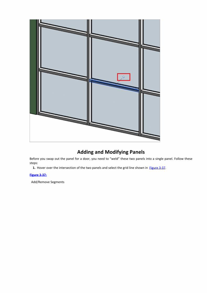
Adding and Modifying PanelsBefore you swap out the panel for a door, you need to “weld” these two panels into a single panel. Follow thesesteps:
1. Hover over the intersection of the two panels and select the grid line shown in Figure 3-37.
Figure 3-37:
Add/Remove Segments

2. Click Add/Remove Segments and then select the grid line that separates the two curtain panels.Now you have a single panel rather than two panels, because the two panels have been welded together.You can swap out the single panel with another panel; when you do so, the entire element is replaced. If you
had not welded these two panels together, only the upper or lower panel would have been replaced individually.
Adding and Modifying the Curtain Panel DoorBefore you swap out the glazed panel for curtain wall doors, let’s load the appropriate family into the project.There’s little point in getting ready to exchange the panel if you don’t have the new panel ready to go!
1. From the Insert tab, select the Load Family option on the Load From Library palette. From the Doors folder,select the Curtain Wall Dbl Glass family. The family is now loaded into our project and you can exchange it forthe default curtain panel.2. You’ll exchange the panel by first selecting the panel that you want to replace. Right away, you can see thatthe panel is also “pinned” since it’s being defined by the type properties for the curtain wall system—just likethe mullions. As you’ll recall, pinned elements can’t be exchanged until they’re unpinned. The same holds truefor this panel.3. Select the panel and unpin the panel. Now you can select a new option from the Properties pallet and replacethe panel with a door, as shown in Figure 3-38.
Figure 3-38: Exchanging the panel for a door

The curtain panel doors automatically expand to fill the space of the entire panel that preceded it. These arespecial doors that are really a curtain panel category. If you want a “real” door, you can swap out the curtain panelfor a wall (even a wall made only of glass), and then place the door in the wall.
Understanding Basic Wall Parts and ParametersWithout going into too much detail, let’s take a moment and discuss some of the various wall types that areavailable in Revit. We don’t think it would be a good idea to have you make all of these now. But it’s good to knowwhat is in the box so that as your design progresses you won’t get the sense that you’ll be backed into a corner.The idea is that once you get the basics down, you’ll want to begin experimenting with more complex wall types.
There are basically three types of walls in Revit: basic, stacked, and curtain walls. Let’s discuss each of thesetypes in a bit more detail.
Basic WallsMany basic walls have no defined vertical information. They’ll be monolithic—like the generic wall type that we’vebeen using for most of these exercises. But in some cases they’ll be specific types of monolithic walls. In thesecases, the structural region is defined.
Select the Generic – 8˝ Masonry wall type and then open the wall’s type properties. Click Preview and selectthe Section view type. In Figure 3-39, the structural region of this wall is defined by a diagonal crosshatch pattern.This is a basic wall with only one pattern defining the wall’s material.
Figure 3-39: Masonry structural region

However, basic walls may show far more vertical information and detail. Select the wall type Exterior - Brick onMtl. Stud and you’ll see the difference (Figure 3-40). Notice that there are numerous values that control thefunction, material, and thickness for this wall type. These values help you coordinate your project informationacross views and schedules. If the wall you select is right anywhere, it’s right everywhere!
Basic walls can even have profiles associated to them. Profiles can be used to add or remove geometry in yourwalls. Take a look at the wall type Exterior - Brick and CMU on MTL. Stud. Note the parapet cap at the top of thewall (Figure 3-41). This is a profile associated to the basic wall type. So while you can manually add profiles to wallsin your project on a case-by-case basis, we think you’ll find adding them to the wall definition makes creating andupdating wall types easy and quick.
Figure 3-40: Vertically compound walls

Figure 3-41: Wall sweep as part of a wall
Stacked Walls
So what are stacked walls? They’re your basic wall types, but in a single defined type. So any of your basic wallscan be used to create a stacked wall.

Look at the wall type Exterior - Brick Over CMU w Metal Stud, shown in Figure 3-42. It’s defined by twodifferent basic walls, but you can add more. However, you can’t combine stacked walls (talk about confusing!) orcurtain walls into your stacked wall.
Figure 3-42: Stacked wall section
Curtain Wall TypesCurtain walls can have complete type definitions (Figure 3-43). The definition will include the mullion type(horizontal and vertical) for the interior and border conditions. But you can also control the horizontal and verticalspacing in the type definition as a type, which is very handy. But what’s really cool is that you can also assign paneltypes to the curtain system type.
Figure 3-43: Curtain wall type definitions

Just One More ThingWalls and curtain walls can be far more complex than the examples you’ve created in this chapter. If you want toexamine all the types, go to the Chapter 3 folder at this book’s web page atwww.sybex.com/go/revit2012essentials and download 03_Walls_and_Curtainwalls.rvt.
First, there’s the option to create walls by picking a face (Figure 3-44). Essentially you create a mass and thenassign walls to the face of the mass. If the mass is modified, you can reassign walls to the modified faces. As youcan see in Figure 3-44, the results can be complex.
Figure 3-44: Walls created by picking a face


Chapter 4
Floors, Roofs, and Ceilings
We’ve approached this chapter by grouping together horizontal host elements that make up your building.Although the initial creation of a floor, roof, or ceiling is somewhat different, the tools used to edit the initialdesign element have a lot of overlap and similarity.
In this chapter, you learn the following skills:Creating floors
Laying out roofs
Adding ceilings
Creating Floors
There are quite a few ways to create floors in Revit. But we honestly don’t have the space to dig deep into all thesevariations! Quite frankly they’re not important for early design iteration.
What’s important is that you understand what the various approaches to a single floor type will do and whatkind of relationships they’ll make. So let’s get started!
Sketching
First, let’s create floors by sketching the desired shape in the Level 1 floor plan view. The floor type that we’ll beusing is Generic – 12ʺ. Start by selecting the Floor tool on the Build panel of the Home tab. You’ll enter Sketchmode, which will allow you to create a sketch that will eventually be used to define the boundary of your floor.
Let’s create a simple sketch for the floor, 15ʹ × 30ʹ [4.5 m × 9 m]. The dimensions are shown for referenceonly. Even though this is a simple shape, what’s more important is how you’ll be able to manipulate the shape.
Finish the sketch and select your default 3D view. Now select the Floor tool and your floor will resemble the onein Figure 4-1.
Figure 4-1: Our finished floor

Editing the BoundaryNote that you’re able to see a couple of things right away in the instant properties: metadata about the floor(location, area, volume, etc.) as well as the ability to revise the geometry via sketching or spot elevations. Let’sselect Edit Boundary and return to the Level 1 floor plan.
Add additional sketch lines to generate the shape at the bottom right of Figure 4-2. Don’t forget to trim backany intersecting lines.
Once this is done and there are no overlapping lines, finish the sketch by clicking the green check button. Selectthe floor and you’ll notice that the options and metadata have already updated, as shown in Figure 4-3.
Now let’s create another floor of the same type and same initial dimensions: 15ʹ× 30ʹ [4.5 m × 9 m], justabove the first floor. Leave some space between the two floors. Offset the floor 1ʹ-0ʺ [300 mm] above Level 1 byentering this distance into the Properties palette. Finish the sketch to complete the floor (Figure 4-4).
Figure 4-2: Modifying the floor sketch
Figure 4-3: The modified floor

Figure 4-4: New floor 1ʹ-0ʺ above Level 1
Sloped Arrows and FloorsNot all floors are flat, and many have large openings. Let’s investigate both options. We’ll begin by bridginganother sloped floor between the first two. Sketch another floor between the two previous floors, filling the gapbetween the two (Figure 4-5).
Figure 4-5: New floor at Level 1
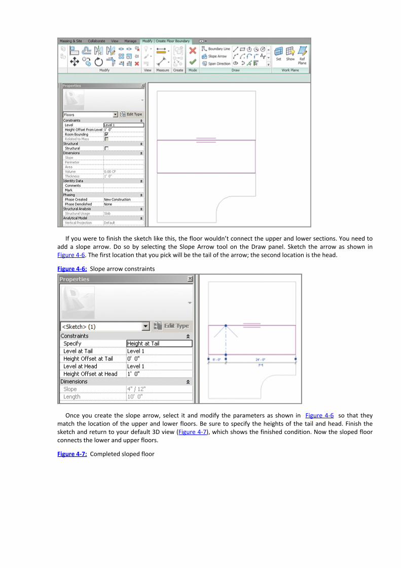
If you were to finish the sketch like this, the floor wouldn’t connect the upper and lower sections. You need toadd a slope arrow. Do so by selecting the Slope Arrow tool on the Draw panel. Sketch the arrow as shown inFigure 4-6. The first location that you pick will be the tail of the arrow; the second location is the head.
Figure 4-6: Slope arrow constraints
Once you create the slope arrow, select it and modify the parameters as shown in Figure 4-6 so that theymatch the location of the upper and lower floors. Be sure to specify the heights of the tail and head. Finish thesketch and return to your default 3D view (Figure 4-7), which shows the finished condition. Now the sloped floorconnects the lower and upper floors.
Figure 4-7: Completed sloped floor

Sloped Floors via Shape EditingSlightly sloped floors and depressions could be created with slope arrows and separate floors—but this approach isprobably too complex since you’d have to create a lot of separate pieces of geometry. For these kinds ofconditions, you have the Shape Editing tools.
Let’s start by returning to Level 1 and selecting the upper floor. Now you can see the Shape Editing tools in theShape Editing panel. Let’s suppose that this entire floor is at the right level, except for one small portion that needsto be slightly depressed in order to accommodate a loading area.
First, let’s define the upper and lower boundaries of this depressed area by selecting the Add Split Line optionfrom the Shape Editing panel. Add the spline lines as shown in Figure 4-8. Dimensions are shown for reference.
Figure 4-8: Adding split lines
Now that you’ve added the proper locations to break the slope, you’ll modify the points at the ends of the linesto change the slope of the floor. Start by returning to your Default 3D View.
As you hover over the endpoint of the line, Revit highlights the shape handles. Press the Tab key to highlight aspecific handle and then select it (Figure 4-9). Now you can adjust the elevation of the shape handle. In this casewe’re depressing the floor, so the value will have to be negative. But you could also increase the elevation in asmall area by using a positive value.
Change the value as shown in Figure 4-9. Then do the same for the shape handle to the right. When you’redone, the depressed area will resemble Figure 4-10.
Figure 4-9: Editing the shape handle

Figure 4-10: The finished depression
Creating Openings by SketchingFor the occasional or irregular opening in a floor, it’s easy to add a secondary opening using the Opening tool.
From the Home tab, select the By Face tool from the Opening panel. Then select an edge of the sloped floorslab you created to enter Sketch mode. Now sketch an opening 10ʹ× 3ʹ [3 m × 1 m] in the center floor panel.
When you finish the sketch, the result will resemble Figure 4-11. There’s no limit to the number of interiorsketches that you can create. You can also edit sketches previously created.
Figure 4-11: The finished opening
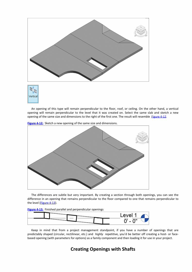
An opening of this type will remain perpendicular to the floor, roof, or ceiling. On the other hand, a verticalopening will remain perpendicular to the level that it was created on. Select the same slab and sketch a newopening of the same size and dimensions to the right of the first one. The result will resemble Figure 4-12.
Figure 4-12: Sketch a new opening of the same size and dimensions.
The differences are subtle but very important. By creating a section through both openings, you can see thedifference in an opening that remains perpendicular to the floor compared to one that remains perpendicular tothe level (Figure 4-13).
Figure 4-13: Finished parallel and perpendicular openings
Keep in mind that from a project management standpoint, if you have a number of openings that arepredictably shaped (circular, rectilinear, etc.) and highly repetitive, you’d be better off creating a host- or face-based opening (with parameters for options) as a family component and then loading it for use in your project.
Creating Openings with Shafts

For openings that occur from level to level with vertical regularity (like a shaft or elevator core), you can use theShaft tool. This tool allows you to create an opening in numerous floors, roofs, and ceilings quickly and easily. Startby adding a few more levels to your project so that you have 10 levels that are evenly spaced.
Select all three floors on Level 1 and copy them by pressing Ctrl+C. Now the geometry is ready to be pasted toeach of the levels. The best way to do this is by using the Paste tool, which allows you to select all the levels towhich you intend to paste the floors. Select Paste from the Clipboard palette and then select Aligned To SelectedLevels (Figure 4-14).
Now you’ll be given the option to select all the levels. Select levels 2–10 (Figure 4-15). The resulting floors areshown in the same figure. Return to the Level 1 view and select the Shaft tool from the Opening panel. Once again,you’ll enter Sketch mode. Create a new rectangle perpendicular to the last two you just drew. Be sure to modifythe top constraint so that the shaft goes up to Level 10. Also be certain to assign a Top Offset value since the upperfloor is slightly above the level (Figure 4-15).
Figure 4-14: Pasted geometry

Figure 4-15: Creating a multistory shaft

Figure 4-16 shows the resulting shaft in 3D. All the floors were automatically cut. Any ceilings, roofs, andadditional floors that may be added in the future will automatically be cut as well.
Figure 4-16: The finished multistory shaft
Picking WallsSelecting walls defines a visual boundary that has been created during the design process; you can also use walls tocreate floors by using this boundary made by the bordering walls. Let’s start by creating a series of walls on Level 1that resembles Figure 4-17.
Figure 4-17: Creating a chain of walls

Now select the Floor tool to enter Sketch mode. But this time, you don’t want to sketch the boundary of thefloor manually. There’s an easier way. Select the Pick Wall tool from the Draw palette. Doing so allows you toselect an individual wall or an entire chain of walls.
Hover over one of the wall edges and then press and release the Tab key. Your selection will “cycle” from onewall to the series of walls. When all of the walls highlight, select them with one pick. Note that the edge of the newfloor will be constructed where your mouse clicks when you pick the wall in reference to the interior or exterior ofthe wall. The floor goes to the outside of the wall; in order to do that, you have to pick the outside edge of thewall—otherwise, the floor aligns with the interior. The entire chain of lines will be created that correspond to all ofthe walls.
If you move the walls that were used to determine the floor sketch, the boundary of the floor will automaticallyupdate. This is incredibly powerful for a multistory building, where updating one floor at a time would be nearlyimpossible. As soon as one update would complete, the design would have likely changed, requiring you to startover.
Laying Out RoofsYou create roofs much like you do floors: from a sketch resulting from either drawn lines or picked walls. And aswith floors, if you pick the exterior walls as a reference, then moving the walls will move the corresponding edgesof the roof. Roofs can also be created in elevation (which we’ll get to in a bit).
Roofs tend to slope, for a lot of good reasons. Let’s create some roofs and investigate a few slope options.
Picking WallsLet’s start by adding a roof to the same walls you used in the previous floor exercise. First, return to your Level 1plan view. Select the Roof tool and choose Roof By Footprint. At this point, Revit will automatically ask you toselect levels this roof is going to be associated with; select Level 3.
Once again, you don’t have to pick all the walls individually or sketch all the roof boundary lines. Select the PickWalls option. Then hover over one of the exterior walls and press the Tab key to select the entire chain. When youselect the entire chain of walls at once, all of the roof boundary lines will be created.

Note the icon with the double arrows. Clicking this icon will flip the boundary lines to the inside or outside ofthe wall face. Click this icon to move all the boundary lines to the inside of the wall’s faces.
Since this will be a sloped roof, you can make the slope perpendicular to the left edge by deselecting theDefines Slope check box for all the other lines. Now define the slope of the left edge with a 1/12 rise over run(about 8 percent).
Finish the sketch and look at the project in 3D. While the roof begins at Level 3 and has the proper slope, it’simmediately obvious that the walls don’t extend beyond the roof.
Revit excels here at helping your team during the design process. Rather than not anticipate a potential conflict,you’re able to identify conflicts earlier rather than later so you can resolve them before other design issues createcircular conflicts.
Select all the walls (using the Tab key to select the entire chain) and set Top Constraint to Level 4 in theProperties palette. The results will resemble Figure 4-18.
Figure 4-18: Adjusting the wall height
Select the roof and reenter Sketch mode. Another option to determine the slope of a roof is using slope arrows.Slope arrows allow you to specify a slope, and they will also allow you to specify the levels of the arrow at both thehead and tail.
The tail of the slope arrow must reside on the boundary of the sketch. But the head of the slope arrow maypoint in practically any direction! Add a slope arrow as shown in Figure 4-19. Note the Height Offset At Head value
is set to 6ʹ [ 2m]. Make sure you uncheck the Define Slope option for the edges of the roof to see the fulleffect of using the Slope Arrow.
Figure 4-19: Sloping the roof

When you finish the sketch, you’ll notice that a single slope proceeds across the roof. A single slope in thisdirection would be nearly impossible to specify without slope arrows.
You can create roof slopes using multiple slope arrows. This technique is incredibly helpful when you want tocreate sloped conditions where two perpendicular slopes must meet at exactly the same location. Again, this issomething that’s difficult to do without slope arrows.
Let’s explore this topic by reentering Sketch mode with the previously created roof. Delete the existing slopearrow by editing the sketch. Now sketch two new slope arrows so that the heads of the arrows meet at the upper-left corner of the roof. The Slope Arrow should have the following properties:
Head Offset At Tail: 0ʺHead Offset At Head: 6ʹ [2 m]Make sure that Height Offset is the same for both Tails and Heads. When you finish the sketch, the results will
resemble Figure 4-20.
Figure 4-20: Sketching two slope arrows

Another common condition in residential-styled roofs is one of multiple slopes that are perpendicular to theirmany edges. To create this condition, you’ll reenter Sketch mode for the previously created roof and start bydeleting both the slope arrows.
Now select all the lines that represent the roof sketch. You can do this by holding down Ctrl and selecting thelines individually or by clicking on one and pressing Tab to highlight the rest of the lines. Once you have themselected, in the Options Bar, enter 3ʹ [1 m] for the overhang. Now select the Defines Slope option for all theboundary edges from the Properties palette. Also modify the Slope property for a slope of 9/12. The roof in Sketchmode should look like Figure 4-21. Finish the sketch.
Figure 4-21: Offsetting the roof sketch and defining slopes
Initially the edges of the wall extend beyond the overhang of the roof. Select all the exterior walls (use the Tabkey) and then select the Attach Top/Base option on the Modify | Wall tab. The result will resemble Figure 4-22.
Figure 4-22: Attaching the walls to the roof
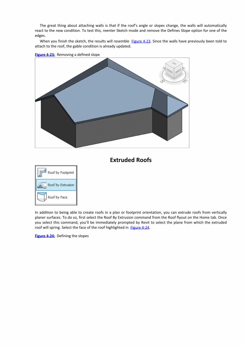
The great thing about attaching walls is that if the roof’s angle or slopes change, the walls will automaticallyreact to the new condition. To test this, reenter Sketch mode and remove the Defines Slope option for one of theedges.
When you finish the sketch, the results will resemble Figure 4-23. Since the walls have previously been told toattach to the roof, the gable condition is already updated.
Figure 4-23: Removing a defined slope
Extruded Roofs
In addition to being able to create roofs in a plan or footprint orientation, you can extrude roofs from verticallyplaner surfaces. To do so, first select the Roof By Extrusion command from the Roof flyout on the Home tab. Onceyou select this command, you’ll be immediately prompted by Revit to select the plane from which the extrudedroof will spring. Select the face of the roof highlighted in Figure 4-24.
Figure 4-24: Defining the slopes

Now you’ll be prompted to associate the roof to the appropriate level. This step is important for schedulingpurposes and you can modify the value later. For now select Level 3 since it’s closest to the base of the extrudedroof.
Next, you’ll create the sketch for the extruded roof. The sketch line will not be a closed loop. It’s just a line (orseries of connected lines) that defines the top of the extruded roof. For this example, you’ll create an arc. Select
the Arc tool from the Draw panel .Now create the arc approximately as shown in Figure 4-25. The important detail is that we’re going to set the
Extrusion End to 20ʹ-0ʺ [6 m].
Figure 4-25: Creating the sketch
When you complete the sketch, the roof is springing from the arc that you created. But it’s not reaching backand connecting to the roof face. This issue is easy to resolve. First, select the roof and then select the Join/UnjoinRoof option on the Geometry panel. Then, hover over the rear edge of the extruded roof, as shown in the leftimage of Figure 4-26. Finally, select the face of the previously created roof that you want to connect the extrudedroof.
Figure 4-26: Attaching the Roof

The extruded roof will now extend back to meet the face of the other roof (Figure 4-27). If either roof ismodified, Revit will do its best to maintain this connected relationship.
Figure 4-27: Joined roofs
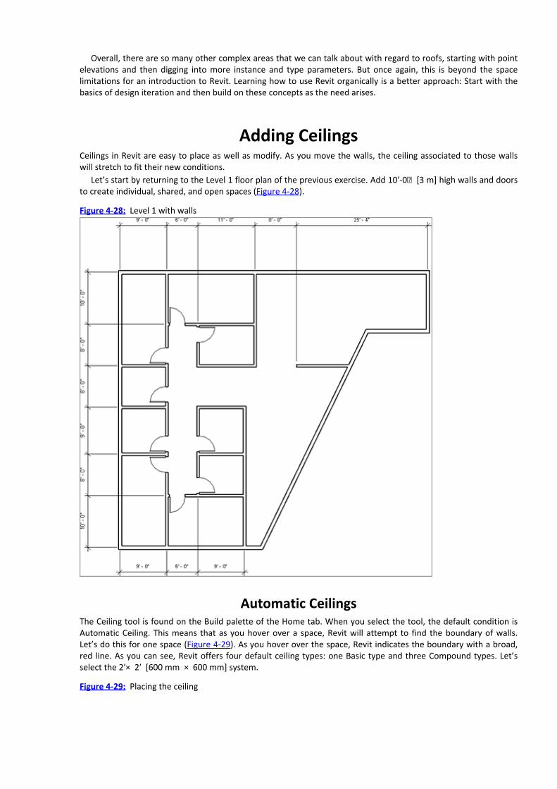
Overall, there are so many other complex areas that we can talk about with regard to roofs, starting with pointelevations and then digging into more instance and type parameters. But once again, this is beyond the spacelimitations for an introduction to Revit. Learning how to use Revit organically is a better approach: Start with thebasics of design iteration and then build on these concepts as the need arises.
Adding CeilingsCeilings in Revit are easy to place as well as modify. As you move the walls, the ceiling associated to those wallswill stretch to fit their new conditions.
Let’s start by returning to the Level 1 floor plan of the previous exercise. Add 10ʹ-0ʺ [3 m] high walls and doorsto create individual, shared, and open spaces (Figure 4-28).
Figure 4-28: Level 1 with walls
Automatic CeilingsThe Ceiling tool is found on the Build palette of the Home tab. When you select the tool, the default condition isAutomatic Ceiling. This means that as you hover over a space, Revit will attempt to find the boundary of walls.Let’s do this for one space (Figure 4-29). As you hover over the space, Revit indicates the boundary with a broad,red line. As you can see, Revit offers four default ceiling types: one Basic type and three Compound types. Let’sselect the 2ʹ× 2ʹ [600 mm × 600 mm] system.
Figure 4-29: Placing the ceiling

As you place the first ceiling in the Floor plan view, you’ll get a warning. This happens frequently and for goodreason. You’ve placed the ceiling but you can’t see it. As a rule, you should not ignore warnings. We’ve seenpeople click and click only to find that they’ve repeatedly placed ceilings in the same space.
Go to the proper view in the Project Browser to see the ceiling—in this case the ceiling plan for Level 1. Nowyou can plainly see the ceiling that you’ve created. Let’s automatically place the remaining ceilings as shown inFigure 4-30. Notice that Revit will center the grid based on the space that you’ve selected.
Figure 4-30: Resulting ceiling

Sketching CeilingsNext, you’ll place ceilings in the upper-left corner of the ceiling plan for Level 1, but this time you’ll share theceiling between the two spaces. This practice is common in interior projects. The partitions only extend to theunderside of the ceiling (rather than connect to the structure above). Begin by selecting Sketch Ceiling on theCeiling panel. Add sketch lines as shown in the first image in Figure 4-31. The result is shown in the second image.
Figure 4-31: Sketching the ceiling

Now let’s place a ceiling in the upper right of the plan, but this time you’ll sketch a 2ʹ× 4ʹ [1.2 m × 600 m]system (Figure 4-32). Choose this new system from the Type Selector before you finish the sketch of the ceiling.
Figure 4-32: 2ʹ× 4ʹ ceiling
And finally, create a GWB on Mtl. Stud Ceiling for the area shown in Figure 4-33.
Figure 4-33: Creating a GWB on Mtl. Stud Ceiling

By default, the GWB material doesn’t have a surface pattern. While this material would be too graphically busyfor walls, it will be fine for ceilings. So let’s create a new material for GWB associated to ceilings and give it apattern.
Select an edge of the ceiling and click Edit Type. Then click the Structure button to open the Edit Assemblywindow. Select the Gypsum Wall Board material option and duplicate the existing material. Name the newmaterial Gypsum Ceiling Board. Now associate a surface pattern called Sand to the material. Click OK until youclose all the dialog boxes and return to the Ceiling plan view. The result is shown in Figure 4-34. You can nowdistinguish the ceiling from the open areas that have no ceiling.
Figure 4-34: Assigning materials to a ceiling

Bulkhead ConditionsCreating a bulkhead to separate two ceilings is straightforward. To begin, place the walls that will act as thebulkhead, as shown in Figure 4-35. Be sure to set the Base Offset value of the walls to 7ʹ-9ʺ [2.3 m] and theUnconnected Height value to 2ʹ-3ʺ [700 cm]. This will create two walls above head height.
Figure 4-35: Creating a bulkhead

It requires a bit of finesse to delete or edit a placed ceiling. Most beginners simply select the grid. But youactually need to select the edge of the ceiling to edit it. Hover over the edge of the ceiling and use the Tab key tocycle through options until the edge of the ceiling is highlighted. Then select it and choose Edit Boundary. Modifythe ceiling as shown in Figure 4-36. Sketch a new GWB ceiling that is 9ʹ-0ʺ [2.7 m] and finish the sketch. Thesecond image in Figure 4-36 shows the finished ceiling.
Figure 4-36: Editing the boundary

To get a better idea of the finished configuration in 3D, go to a 3D view and orient a section box of the Level 1plan view. Right-click the ViewCube and from the Floor Plans flyout of the context menu, select Level 1. Use thegrip arrows to pull the boundaries of the section box to resemble Figure 4-37. You’ll find that working this way ishelpful because having both 2D and 3D views aids in communicating the design issues.
Figure 4-37: Orienting the section box to the 3D view

Adding Lights and Rotating the GridAdding lights is easy and since they’re hosted by the ceiling, lights will often create openings for you. Let’s begin byloading one of the lighting families.
From the Insert tab, select Load Family from the Load From Library panel. Open the Lighting Fixtures folderand double-click on the family Ceiling Light – Linear Box.rfa.
You’ll be prompted to place the first family type of the family in your ceiling, but be sure to select the 2ʹ× 4ʹtype from the Type Selector. You’ll place lighting fixtures into the 2ʹ× 4ʹ ceiling in the upper-right ceiling plan.
As you will notice, the insertion point for the light is the center of the light. So place the first light and then usethe Align tool to get the first one into the right spot. Then copy the first light based on the intersection of theceiling grid. All of the lights are shown in Figure 4-38 on the left. To rotate the grid, select any grid line and usethe Rotate tool rotate the grid line. In this case, we specified a 10-degree angle. You’ll notice the lights haverotated as well.
Now press and drag the ceiling grid lines to better center the lights in the overall space. Again, the lights havemoved with the grid. This technique is incredibly helpful for maintaining design coordination. The finishedcondition is in Figure 4-38 on the right.
Figure 4-38: Placing lights and rotating the grid

Changing the CeilingCeiling types often change in the design process. Again, where most beginners struggle is mistakenly selecting theceiling grid (which is actually selecting the material). But you need to select the geometry of the ceiling, which youdo by selecting the edge of the ceiling.
Select the edge of the ceiling and then you’ll be able to pull down the Properties menu to select the GWBoption for this ceiling (Figure 4-39). The result is shown in the second image in Figure 4-39.
Figure 4-39: Selecting ceiling geometry
Sloping the CeilingWe can even slope the ceiling by placing a slope arrow while editing the boundary of the ceiling. This is basically


Chapter 5
Stairs, Ramps, and Railings
Revit is capable of creating wonderfully complex and elegant stairs, ramps, and railings. But to get started, youneed to understand the basic functionality so that you can confidentially resolve design intent. Then once thedesign intent is resolved, you’ll have plenty of time to go back and modify the stair and revise the entire designquickly and easily!
In this chapter, you learn the following skills:Creating numerous stair configurations
Designing ramps
Building railings for level and sloped conditions
Working with parts, parameters, and properties
Creating Numerous Stair ConfigurationsStairs contain many, many parameters, but not all of the parameter controls are going to be equally importantduring the design process. Design is often about the intent of what something is as well as where it is meant to go.Once the intent is resolved, it’s necessary to go back and revise the specifics of how something will be carefullyassembled.
Let’s first simplify the default railing that is associated to the stairs. The default railing is very busy from a designstandpoint. It contains lots of balusters, which are graphically distracting. It’s important that you indicate thehandrail and nothing more.
Creating the “Generic” Railing
Open the default template and expand the Family tree in the Project Browser. As you can see, four railingdefinitions exist in the project: Guardrail – Pipe through Handrail – Rectangular. There are also two types of stairfamilies in the default template: the Monolithic stair family and the 7 Max Riser 11ʺ Tread stair family.
Let’s start by creating a railing that is useful from a design standpoint. Too much specificity too soon can cause alot of confusion, so you’ll simplify the geometry. You’ll do this by duplicating a railing definition that’s close to whatyou need and then modify it to suit your purposes.
Here are the steps to duplicating and creating your own custom handrail that you’ll use for designing stairs. Forthese exercises, you’re going to work from the c05_Stairs_Ramps_Railings.rvt file found on the book’scompanion web page, www.sybex.com/go/revit2012essentials.
1. Right-click on Handrail – Pipe and select Duplicate.2. Right-click on the duplicated handrail and select Rename. Rename the duplicate handrail to Handrail –Design.3. Select the handrail that you’ve just created and drag it into your Level 1 view. Doing so initiates the Railingcommand and allows you to draw a portion of the railing that you’ve selected.4. Create a 24ʹ [7.3 m] long segment.5. Select the Finish command and go to your 3D view. As you can see in Figure 5-1, there are balusters and railsbelow the handrail portion of the railing; you’ll simplify this area to create your design railing.
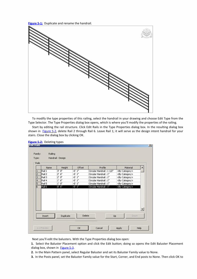
Figure 5-1: Duplicate and rename the handrail.
To modify the type properties of this railing, select the handrail in your drawing and choose Edit Type from theType Selector. The Type Properties dialog box opens, which is where you’ll modify the properties of the railing.
Start by editing the rail structure. Click Edit Rails in the Type Properties dialog box. In the resulting dialog boxshown in Figure 5-2, delete Rail 2 through Rail 6. Leave Rail 1; it will serve as the design intent handrail for yourstairs. Close the dialog box by clicking OK.
Figure 5-2: Deleting types
Next you’ll edit the balusters. With the Type Properties dialog box open:1. Select the Baluster Placement option and click the Edit button; doing so opens the Edit Baluster Placementdialog box, shown in Figure 5-3.2. In the Main Pattern panel, select Regular Baluster and set its Baluster Family value to None.3. In the Posts panel, set the Baluster Family value for the Start, Corner, and End posts to None. Then click OK to

close the Edit Baluster Placement dialog box and click OK again to close the Type Properties dialog box. Theimage shows a railing with a handrail only, but for design purposes, this is exactly what you need in order toexpress design intent.
Figure 5-3: Edit Baluster Placement settings
Now let’s start creating our “design” stair.
Creating Your Design StairBy default, there are two types of stairs in your Revit project. Let’s duplicate the 7” Max Riser 11ʺ Tread stairfamily type in the Project Browser and name the duplicate Stair-Design. This is the stair that you’ll use to createnumerous configurations.
Straight RunLet’s start by creating a straight run stair. Select the Stairs tool from the Circulation panel of the Home tab on theribbon. Or, drag the component name into the project view to activate the Stairs tool.
1. From the Level 1 plan view, pick a point to the left and then move your cursor to the right. As you do, you’llnotice that Revit is telling you how many treads remain to complete a stair that starts on Level 1 through Level 2(Figure 5-4).
Figure 5-4:
Sketching the straight run stair

2. Select the Railings Type option in the Tools palette. Specify the Handrail – Design type that you createdearlier, as shown in Figure 5-5. This will be the default handrail that Revit will use whenever you create this stairuntil you specify another type.
Figure 5-5:
Specifying the railings type
3. Finish the Sketch mode. The resulting stair is shown in Figure 5-6.
Figure 5-6: The resulting stair

Straight Run with Landing
What you just created is the most basic type of stair: a straight run with a pair of railings. However, it’s importantto understand how to create a variety of stair types, including stairs with landings. Follow these steps to start yourfirst straight run of stairs.
1. Let’s start the sketch this time from the ribbon. Choose the Home tab, and then click the Stairs button in theCirculation panel. Doing so starts your stair in Sketch mode. Begin by drawing a straight run, but stop abouthalfway through the run.2. Start the second run of stairs, as shown in Figure 5-7. When you finish the second run of stairs, you’ll noticethat Revit creates the landing between the two runs automatically.

Figure 5-7:
A second run of stairs and landing
3. Finish the sketch and the stair will resemble Figure 5-8.
Figure 5-8: Complete stairs with a middle landing
Multistory RunsFor multistory runs, Revit is able to take a stair that only goes between two levels and repeat it continuously. Butthis will only work if all of the level-to-level heights are identical. Let’s turn one of the stairs that we’ve created intoa multistory stair. It’s easy!

1. First, you need to create some additional levels. As shown in Figure 5-9, open the South elevation and clickthe Level tool on the Datum panel of the Home tab. Click on the elevation and drag the mouse from left to rightto place the level, taking care that the heights are equally spaced.As discussed earlier, you can change the level heights by clicking the blue elevation text. For this example, werepeated the levels at 10ʹ-0ʺ [3 m] increments—up to 40ʹ-0ʺ [15m)].Figure 5-9shows several stair types, including the ones you’ve created.
Figure 5-9:
Adding additional levels to the model
2. Select any of the stairs you’ve created. Highlight one of the stair runs and look at its properties in theProperties palette. You’ll see there’s an option to designate the Multistory Top Level. Set it to Level 5, as shownin Figure 5-10.
Figure 5-10:
Changing the properties for a multistory stair
3. Once you complete the multistory stair, the stair will quickly propagate across all levels (Figure 5-11). If youedit the stair or railings associated to the multistory stair, the entire multistory configuration changes as well.
Figure 5-11: The completed multistory stair
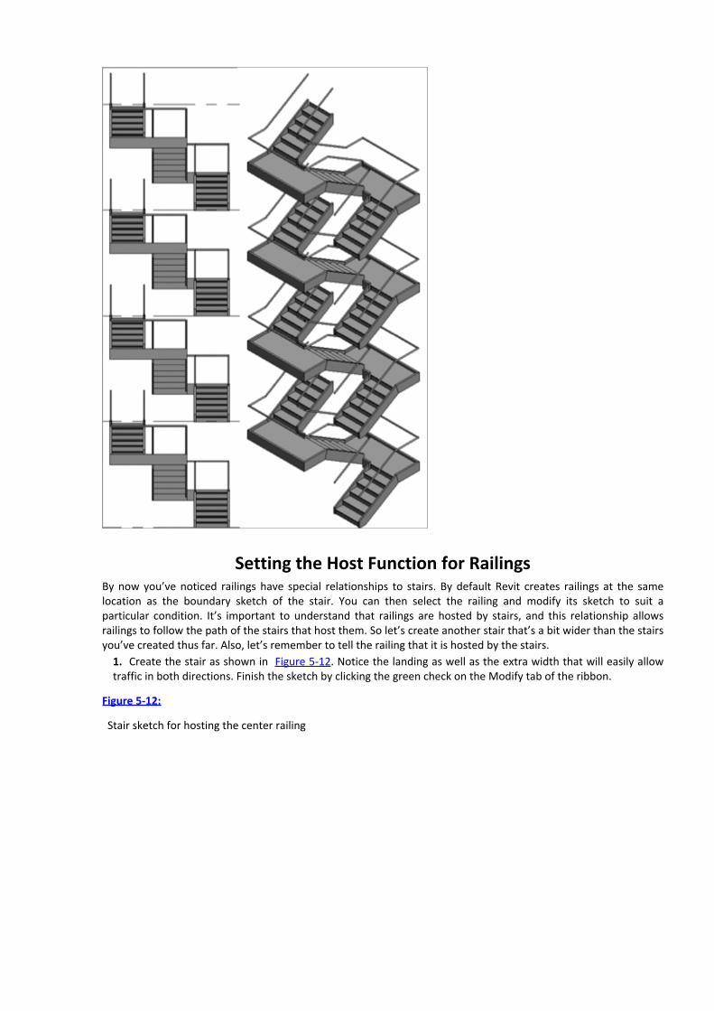
Setting the Host Function for RailingsBy now you’ve noticed railings have special relationships to stairs. By default Revit creates railings at the samelocation as the boundary sketch of the stair. You can then select the railing and modify its sketch to suit aparticular condition. It’s important to understand that railings are hosted by stairs, and this relationship allowsrailings to follow the path of the stairs that host them. So let’s create another stair that’s a bit wider than the stairsyou’ve created thus far. Also, let’s remember to tell the railing that it is hosted by the stairs.
1. Create the stair as shown in Figure 5-12. Notice the landing as well as the extra width that will easily allowtraffic in both directions. Finish the sketch by clicking the green check on the Modify tab of the ribbon.
Figure 5-12:
Stair sketch for hosting the center railing

2. Add two separate railing sketches: one for the lower run and another for the upper run. And while you’re atit, you’ll also include the handrail extensions.3. Drag the Handrail – Design railing type into the project view. Revit will initiate the Railing tool for you andselect the railing. Sketch the lower railing as shown in Figure 5-13. Add the extensions shown as separate sketchlines.
Figure 5-13:
Lower railing sketch
4. Before you complete the sketch, be sure to set the stair as the host for the railing. Click the Pick New Hosticon on the Tools palette; then select the stair. It will highlight when you hover over the stair.5. Finish the stair and the view will resemble the left side of Figure 5-14. Now create the second sketch for theupper railing. Don’t forget to extend the railing beyond the lower treads and add the extension. The results willresemble the image on the right of Figure 5-14. Don’t forget to set the host each time you create a new railing!
Figure 5-14: Handrail extensions

One final note: not only is hosting important for railings and stairs, but it’s also something that you’ll deal withwhen creating ramps as well as sloped floors.
Designing RampsNow that you’re familiar with designing a number of stair configurations, ramps will come easy. It’s the same basicprocess of sketching a desired shape and then completing the sketch—with one major difference: far morefrequent landings and a shallower slope.
You access the Ramp tool from the Circulation panel on the Home tab or by dragging the desired ramp from thelist of families in the Project Browser. For the following exercises, let’s just use Ramp 1.
Keep in mind that ramps have different constraints than stairs. We’ll cover some details of these constraints atthe end of this chapter. For now, just understand that the maximum length of a ramp in one section is 30ʹ-0ʺ[9m)] and a 1:12 slope (8 percent). These parameters can be changed, but by default they correlate to commoncode requirements.
Straight RunsLet’s start by creating a straight run. Because we’re traversing Level 1 to Level 2 (and they are 10ʹ [3 m] apart), thiswill require a ramp length of 120ʹ [36.5 m] at a maximum 1:12 slope, not including landings. You’ll be limited toruns of 30ʹ [9 m] in length. So right off the bat, you know that four runs will be required with three landings.
1. Sketch the straight runs as shown in Figure 5-15.
Figure 5-15:
Straight runs of ramps

2. Note that the run lines that indicate slope versus landings are different. Blue lines indicate slope whereasblack lines indicate level landings.3. Finish the sketch. You’ll see something like Figure 5-16, which displays the results in 3D.
Figure 5-16: Straight runs of ramps
The process is the same as that for all the other stair configurations you’ve created. Multistory rules arepermitted, and you must use the Set Host function when creating additional railings.
Editing Boundary ConditionsEditing boundary conditions of both stairs and ramps typically modify the railings associated with those elements.Let’s test this now with the ramp you just created.
1. Return to Level 1, select the ramp, and enter Sketch mode.2. Delete the boundary lines that represent the landings, as shown in Figure 5-17.
Figure 5-17:

Straight runs of ramps
3. Select the Boundary tool and then choose the Tangent Arc tool.
4. Create the new boundaries shown in Figure 5-18 by picking one boundary edge and then the other. Thenfinish the sketch. The finished ramp in 3D is shown on the right in Figure 5-18. Notice that Revit has alreadymodified the railings to accommodate the new boundary.
Figure 5-18: Modified ramp with curved boundary
Building Railings for Level and Sloped Conditions
Railings are created much like stairs and ramps; you select the tool, enter Sketch mode, create your linework, andthen finish the sketch. The Railing tool can be found on the Circulation panel of the Home tab in the ribbon, or youcan drag the desired railing type from the Project Browser into the project view window.
Sketches for railings can consist of a series of connected lines, but sketches with gaps or overlapping lines aren’tpermitted. Sketches that cross or fail to intersect properly will also produce an error message. Both sketches in

shown in Figure 5-19 would not be completed.
Figure 5-19: A doesn’t join; B crosses itself.
If you attempt to complete railings like either of the ones in Figure 5-19, you’ll get the warning shown in Figure5-20.
Figure 5-20: You’ll see this error message.
Floors can also be sloped, so let’s create this condition as well.1. Start by creating a floor as shown in Figure 5-21 from the Build panel of the Home tab. If you need to reviewhow to create floors, please refer to Chapter 4, “Floors, Roofs, and Ceilings.”
Figure 5-21:
Creating a floor
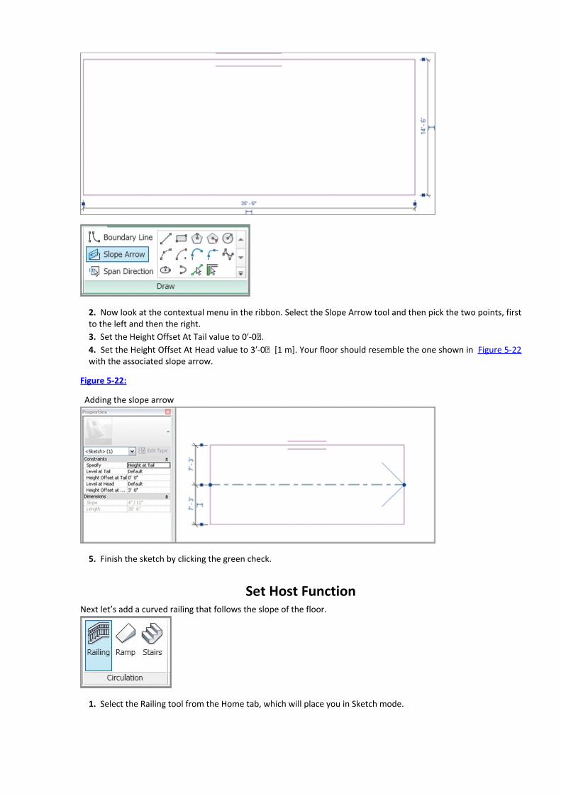
2. Now look at the contextual menu in the ribbon. Select the Slope Arrow tool and then pick the two points, firstto the left and then the right.3. Set the Height Offset At Tail value to 0ʹ-0ʺ.4. Set the Height Offset At Head value to 3ʹ-0ʺ [1 m]. Your floor should resemble the one shown in Figure 5-22with the associated slope arrow.
Figure 5-22:
Adding the slope arrow
5. Finish the sketch by clicking the green check.
Set Host FunctionNext let’s add a curved railing that follows the slope of the floor.
1. Select the Railing tool from the Home tab, which will place you in Sketch mode.

2. Select Pick New Host and then select the floor you just created.3. Create a curved sketch for the railing, as shown in Figure 5-23. Then finish the sketch by clicking the greencheck. That’s all there is to it! The railing will now follow the path of the floor, even if you change theconfiguration of the railing sketch or the slope direction of the floor.
Figure 5-23: Curved railing sketch in elevation view
Working with Parts, Parameters, and PropertiesSo far you’ve been getting familiar with sketching various configurations for generic stairs, ramps, and railings.Now let’s dig a little deeper to explore the properties of these three system families so you’ll know how they affectthese families. We’ll begin with stairs.
Stair Parameters
Start by creating a section through the U-Shaped in our Revit file. The Section tool can be found in the QAT toolbaror in the View tab.
Open the section by double-clicking the blue section head. Adjust the section so that you can see the full flightof stairs. Select the stair and take a look at the instance parameters in the Properties palette. These are essentiallyself-explanatory and deal with the stair materiality, nosing overhang, and some other basic stair properties. Youcan try adjusting some of them to visualize the changes here in section.
Next, look at the type properties. With the stair still selected, click Edit Type to open the Type Properties dialogbox for the stairs, shown in Figure 5-24. Let’s step through some of the key ones and explain what you need to do

to change them.
Figure 5-24: The stair type properties
Extend Below Base Extend Below Base will continue the structure of the Stringer below the base level of thestair. Set the value to –1ʹ-0ʺ [30 cm] and the results should be easy to see in section.
Monolithic Stairs Checking the Monolithic Stairs option will activate the next two options. They don’t apply forthis particular stair since we’re only going up one level. For more information on Monolithic stairs, review thesection “Creating the ‘Generic’ Railing,” earlier in this chapter.
Function The Function option allows you to designate the stair as an interior or exterior type. It doesn’t changethe geometry in any way; it’s more of a scheduling function.
Break Symbol The Break Symbol option controls the graphic break line. If checked, the condition on the right ofFigure 5-25 is shown. If unchecked, the break symbol disappears and it is represented as a single line.
Figure 5-25: Break Symbol option

Text Size and Text Font The Text Size and Text Font options refer to the “UP” or “DOWN” text. (This reports thedirection of the stair.)
Material and Finishes The Material and Finishes options control the shaded and rendered material assignmentsfor the stairs.
Treads Figure 5-26 indicates the corresponding dimensions from the Treads section. The Nosing Profile (ifapplied) is associated to the front of the tread, but can also be associated to either side, or even all three sides.
Figure 5-26: Changing stair nosings
Risers The Risers function allows you to control the absence or presence of a riser, as well as what type (straightor slanted). Extending the tread under the riser will result in the image on the left of Figure 5-27, whereasextending the riser behind the tread will result in the image on the right.
Figure 5-27: Extending the riser location

Stringers Stringer properties control the properties of both left and right stringers. Stringer Height is the depthof the stringer as measured from edge to parallel edge (Figure 5-28).
Figure 5-28: Stringer Height
Stair Carriages Stair Carriages are simply the structural framing that supports the treads and landings.
Carriage Heights Carriage Heights are dimensional clearances between the carriage to the treads and landings.
Ramp ParametersAs with stairs, the type parameters of ramps contain most of the information you’ll need to set the rules of theramp. To view the properties, follow these steps:
1. Create a section of the first ramp in the same way you created the section of the stair.2. Open the section and select the ramp.3. Select Type Properties from the Properties palette. The dialog box shown in Figure 5-29 appears.
Figure 5-29: Type Properties for the ramp

We’re most concerned with two values. The first is Maximum Incline Length. This value determines themaximum continuous length that will be allowed before you have to create a landing. The second value is RampMax Slope, and it is expressed as a rise-to-run ratio or percentage based on your project settings.
Railing ParametersAfter stairs, railing parameters are probably the most unfamiliar part of Revit for new users, so let’s investigatewhat the parameters control. Since many of these values don’t do anything clearly noticeable for stand-alongrailings, we’ll use the same U-Shaped stair that we used to understand important stair parameters.
First, select the inner railing and click Edit Type in the Properties palette. Look at the Rail Structure and BalusterPlacement fields.
Rail Structure The Rail Structure option controls all the horizontal sweeps that are associated with a railing. Arailing can have many, many horizontal sweeps.
Balusters The balusters are any vertical elements, and they can be specified depending on location of use. Thefour options that Revit gives you are Start Post and End Post, Main Baluster Pattern, and Corner Post.
Baluster Offset The Baluster Offset value controls all baluster positions to the left or right of the sketched linethat creates the baluster. It’s convenient to be able to move all the balusters to the left or right from thisparameter. But another reason is that there are frequently conditions where the sketched line must reside ona host (like on stairs or a ramp). Yet the actual baluster geometry may need to reside on the stringer or beyondthe edge of the ramp.
Landing Height Adjustment The Landing Height Adjustment value raises or lowers the height of the railing basedon the value given (and whether the box is checked). Figure 5-30 shows the unchecked result.
Figure 5-30: No Landing Height Adjustment
Figure 5-31 shows the checked result with a value of 1ʹ-0ʺ [30 cm]. Notice that with the landing heightadjustment selected, the railings have moved up in elevation.
Figure 5-31: With Landing Height Adjustment
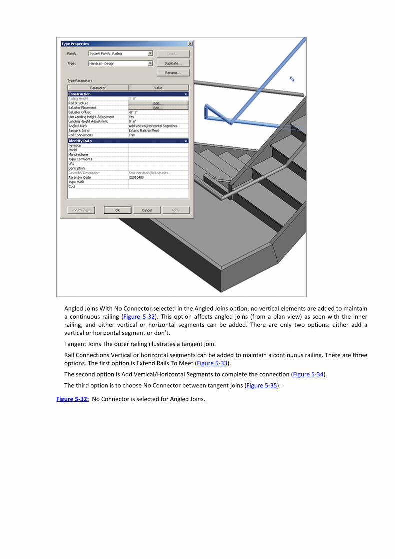
Angled Joins With No Connector selected in the Angled Joins option, no vertical elements are added to maintaina continuous railing (Figure 5-32). This option affects angled joins (from a plan view) as seen with the innerrailing, and either vertical or horizontal segments can be added. There are only two options: either add avertical or horizontal segment or don’t.
Tangent Joins The outer railing illustrates a tangent join.
Rail Connections Vertical or horizontal segments can be added to maintain a continuous railing. There are threeoptions. The first option is Extend Rails To Meet (Figure 5-33).
The second option is Add Vertical/Horizontal Segments to complete the connection (Figure 5-34).
The third option is to choose No Connector between tangent joins (Figure 5-35).
Figure 5-32: No Connector is selected for Angled Joins.
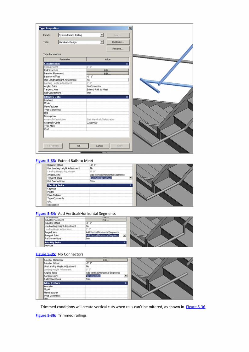
Figure 5-33: Extend Rails to Meet
Figure 5-34: Add Vertical/Horizontal Segments
Figure 5-35: No Connectors
Trimmed conditions will create vertical cuts when rails can’t be mitered, as shown in Figure 5-36.
Figure 5-36: Trimmed railings

But if Weld is selected, Revit will try to join the railings as close as possible to a mitered condition (Figure 5-37).
Figure 5-37: Welded railings
If you would like to download the completed Revit file that was created during this chapter, you can downloadit from the book’s companion web page. The file is named c05_Stairs_Ramps_Railings.rvt.
Just One More ThingKeep in mind that what you start with can be quickly and easily swapped out with more complex configurationsand designs later. The important thing during design is that you resolve what something is and where it is. Thenafter the initial design is approved you can return to your intent and begin to specifically resolve the details andhow it will be assembled.
Revit can be used to create incredibly complex and compelling stairs and railings! Creating these types ofsystem families are discussed in depth in Mastering Autodesk Revit Architecture by Krygiel, Read, andVandezande (Sybex 2011).
Again, don’t get ahead of yourself. Concentrate on the basics. Once you have those down you’ll be able tocreate far more detailed stairs, ramps, and railings.
Stairs and railings can not only be architectural works of art, but equally creative in Revit if you really leveragethe tools available. Below is an example of what you can create if you stretch the limits of the Stairs tool. Yourstairs can be elegant and versatile. The image on the bottom left is a very creative use of the stair tool—as anelevated railing system! The bollards hold up the track (which is the railing).


Chapter 6
Adding Families
Revit includes quite a few family categories. Becoming familiar with the various categories will help you developthe right lexicon of terms and understanding. There are families in the project environment (system families) likeWalls, Floors, and Roofs—basically anything that is defined and created directly in the project. But there are otherfamilies created outside the project in the Family Editor. These are referred to as component families. In thischapter, we’ll be dealing only with component families.
In this chapter, you learn the following skills:Understanding different family types
Loading families
Placing families
Understanding Different Family Types
There are various family types and many behave somewhat similarly. In some cases you can change the familydefinition from one category to another. But in other cases, the behavior is unique to a family, and families can’tbe changed to another category.
There are only two important things to remember. First, schedules are based on family categories. So when youcreate a schedule, you’ll be scheduling inside a single category as shown in Figure 6-1.
Figure 6-1: Schedule categories

Second, you load families into your project based on their category. The Revit library is organized intoreal-world categories, so even if you’ve never used Revit before today, finding the right content (or at least a goodplaceholder during design iteration) should be straightforward (Figure 6-2).
Figure 6-2: Loading families by category
Now let’s discuss some of the family categories in Revit. We’re not going to do this alphabetically (as shown inthe list in Figure 6-2). We’ll progress with regard to how things behave and whether they’re one-, two-, or three-dimensional.
Loading Families
You load component families into your project by selecting the Insert tab, and on the Load From Library panel,clicking Load Family. If the family that you’re looking for isn’t in the default Revit library, don’t panic. You can alsotry Autodesk Seek, an online repository of content in many different formats. Type your search term in theAutodesk Seek panel (Figure 6-3) or go to http://seek.autodesk.com/.
Figure 6-3: Autodesk Seek
Another great website for user-created content (Figure 6-4) is RevitCity (www.revitcity.com). Sometimesdownloading a good placeholder during design is much faster than modeling it from scratch!
Figure 6-4: RevitCity offers user-created content.

Remember that whenever you place any content in your project (particularly from nonofficial Autodesksources), you should take a moment to review the family components. It could be overly detailed or contain non-native Revit elements, and by using it you run the risk of slowing down your project’s performance.
Placing FamiliesPlacing families in your project is easy to do. Be aware that a family’s category will determine from where it isloaded and how it can be placed. Once the family has been placed, its relationship to other elements in the modelwill determine how it continues to behave as your project evolves.
In this section, we’ll investigate how you place families of different categories in your project.
AnnotationsAnnotations are graphics that are used in your project. Some are intended for use across all project disciplines,such as Area Tag, Callout Head, and Centerline. Other annotations are discipline specific to architecture, structure,mechanical, and so forth. Architecture, for example, includes Casework Tag, Ceiling Tag (with or without Height),and Stair Tag.
The default project template has many annotations preloaded (Figure 6-5). If you don’t have the rightannotation loaded and you try to use one, Revit prompts you to load the correct category.
Figure 6-5: Preloaded annotations
Let’s look at an example. Place the desk (one is already preloaded in the template) in your project. Then selectthe Tag panel on the Annotate tab and click Tag By Category.
Now select the desk. Because no furniture tag annotation has been loaded, Revit prompts you to load one fromthe appropriate category.

To do so, first select the Annotations folder. Then select the Architectural folder and click Furniture SystemTag (Figure 6-6). Click the Open button to load the tag into your project.
Figure 6-6: Selecting the Furniture system tag
Now you can tag the desk with the correct annotation. You can even select a custom tag end (like an arrowheador heavy tick). When you fill out the value of the tag, every element of the same type will be immediately updated(Figure 6-7).
Figure 6-7: Tagging the desk

Don’t worry when you select other views in your project and don’t see the tag in those views. With fewexceptions, all 2D elements, including annotations, are specific to each view.
ProfilesMany profiles are preloaded in the Revit template (Figure 6-8). These profile families are a single loop of lines thatare created in 2D. Once they are loaded in a project, they can be associated with other system families.
Figure 6-8: Preloaded profiles
Profiles aren’t used in a stand-alone fashion; they’re used in combination with other components. For example,a profile family defines the cross section of a handrail. The parapet cap shown in Figure 6-9 is defined by a profile.
Figure 6-9: Parapet cap profile

Detail ComponentsDetail components are 2D objects that are used to complete your details. Sometimes they’re 2D representations of3D objects, like the bond beam shown in Figure 6-10. Go ahead and load this family into your project.
Figure 6-10: Bond Beam detail component

Detail components are a lot like blocks in AutoCAD. While you could draft all of your details manually, detailcomponents help coordinate all the repetitive 2D elements that complete an assemblage. To place a detailcomponent, click the Component button on the Detail panel of the Annotate tab.
Detail components can also be parametric, which means that a single component can have parameters thatallow many types to be created from a single family (Figure 6-11). For example, once you load the Bond Beamcomponent, you’ll see that it helps you coordinate your project.
Figure 6-11: Parametric types
In other cases, the detail component is just a graphic element, like the break line shown in Figure 6-12. Thebreak line is used to mask the geometry beyond the view and serves as a graphic convention that lets you knowthe element continues beyond the view boundaries.
Figure 6-12: Break line detail component

Repeating DetailsRepeating details are based on component families that are given rules to repeat based on some defined interval(Figure 6-13). Brick and mortar will repeat three times in 8ʺ [200mm]. A rule can be applied to this so the brickdetail can be drawn like a line—lengthened and shortened while keeping a consistent pattern. The old method ofdoing this was to draw one brick and array it in a straight line. Changes to that line meant redoing the array, so thisis much easier. You’ll find repeating details on the Component flyout of the Detail panel on the Annotate tab.
Figure 6-13: Selecting a repeating detail component
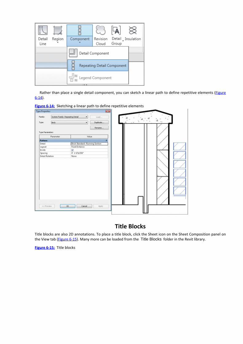
Rather than place a single detail component, you can sketch a linear path to define repetitive elements (Figure6-14).
Figure 6-14: Sketching a linear path to define repetitive elements
Title BlocksTitle blocks are also 2D annotations. To place a title block, click the Sheet icon on the Sheet Composition panel onthe View tab (Figure 6-15). Many more can be loaded from the Title Blocks folder in the Revit library.
Figure 6-15: Title blocks

Level BasedWhen you place a family in your project, it usually has a relationship to something else in your project. But this isnot necessarily a relationship to another piece of geometry. In many cases, the family will be constrained to thelevel on which it was placed. The level constraint is reflected in the instance parameters of the desk you placedearlier, as shown in Figure 6-16.
Many objects in Revit are constrained by their level. You want to be especially careful when dealing with levelconstraints. If you delete a constraint—in this case, the level—the objects constrained by that level will also bedeleted. Revit displays the warning shown in Figure 6-17.
Figure 6-16: Level constraint for the desk
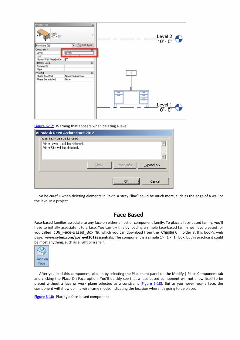
Figure 6-17: Warning that appears when deleting a level
So be careful when deleting elements in Revit. A stray “line” could be much more, such as the edge of a wall orthe level in a project.
Face BasedFace-based families associate to any face on either a host or component family. To place a face-based family, you’llhave to initially associate it to a face. You can try this by loading a simple face-based family we have created foryou called c06_Face-Based_Box.rfa, which you can download from the Chapter 6 folder at this book’s webpage, www.sybex.com/go/revit2012essentials. The component is a simple 1ʹ× 1ʹ× 1ʹ box, but in practice it couldbe most anything, such as a light or a shelf.
After you load this component, place it by selecting the Placement panel on the Modify | Place Component taband clicking the Place On Face option. You’ll quickly see that a face-based component will not allow itself to beplaced without a face or work plane selected as a constraint (Figure 6-18). But as you hover near a face, thecomponent will show up in a wireframe mode, indicating the location where it’s going to be placed.
Figure 6-18: Placing a face-based component

An interesting thing about face-based families is that if their constraint is deleted, the element remains in theproject (even if the constraint is a level). When you select the component, Revit prompts you to pick a new face toassociate with the element (click the Pick New button on the Work Plane panel of the Modify | Generic Modelstab).
HostedA hosted family has a specific relationship to a specific host category, such as Floors, Walls, Roofs, or Ceilings.Without the host, the hosted family can’t be placed. For example, a wall-hosted family will only allow itself to beplaced in a wall.
Furthermore, if the host is removed, the hosted families are also deleted. Keep in mind that you will not bewarned when the hosted elements are being deleted. Here are examples of commonly hosted relationshipsbetween system and component families:
Walls: Windows and Doors
Curtain Walls: Curtain Panels and Mullions
Ceilings: Lighting Fixtures
Railings: Balusters
You can see how this feature works by creating a 10ʹ-0ʺ [3 m] length of a Generic - 6ʺ wall. Then go to yourdefault 3D view.

Select the Door tool from the Build panel of the Home tab, and you’ll notice that you can’t place a door untilyou hover over the host wall. Place a door as shown in Figure 6-19. Then place some windows in the same wallsection, as shown in Figure 6-20.
Figure 6-19: Placing a door
Figure 6-20: Placing two windows


Chapter 7
Modifying Families
Now that you have added a number of families to your Revit project and the design has progressed, you’ll oftenfind it necessary to modify the families. Sometimes swapping out a less-detailed family component for one that ismore exact and correct is the best solution (and in some cases opening it and modifying it slightly). In other cases,it’s simply a matter of opening the component family that you started with and tweaking the geometry to better fityour design. Either solution is viable—which you choose depends on the result that is better for your designprocess.
In this chapter, you learn the following skills:Editing view display and detail level
Changing the family category
Modifying family geometry
Editing View Display and Detail LevelAdding content is pretty straightforward, but learning to modify it will take a bit more time. We’ll use the lastexercise from Chapter 6, “Adding Families” as a starting point for the exercises in this chapter. Open your finishedproject file now, or download the file c06_Adding_Families.rvt from the book’s web page.
To download the project and content you create during this chapter, go towww.sybex.com/go/revit2012essentials. From there you can download the project filec07_Modifying_Families.rvt. You can also download the family files c07_Three_Light_Fixed.rfa andc07_L_Shaped_Handrail.rvt.
One of the first things that you want to consider when loading a family into your project is the level of detailthat the family displays at different orientations and scales. It’s not likely that every part of a component familyneeds to display at all scales. It’s more likely that too much detail will be confusing (particularly at smaller scales).Just a decade or so ago when we used pencils, knowing when to stop drawing detail was pretty easy. But high-resolution computer displays that give you the ability to zoom in and out as well as modern printing technologieshave allowed us to create far more detail than is necessary (or meaningful). So how do you display just the rightlevel of detail in Revit?
First, go to the South elevation of our project. Create a copy of the desk to the right of the first one. You canzoom to fit by right-clicking in the view and selecting Zoom To Fit. But this only shows you everything in yourview—it doesn’t give you a sense of what is going to legibly print (Figure 7-1).
Figure 7-1: Zoom To Fit

A great way to tell what is going to be graphically legible when you print is to select the Zoom Sheet Size optionfrom the Navigation bar on the right side of the view. Doing so will take the scale of the view into account whenzooming in (or out). The difference is shown in Figure 7-2. If you find yourself needing to see what’s important in aview (and you don’t want to get too carried away with details that don’t yet matter), this is a great tool.
Figure 7-2: Zoom Sheet Size
Something that you’ll notice from both of the previous figures is that the hardware on the desk is completelyvisible in both views—which is reasonable to expect. But let’s see what happens when the view scale changes.

Figure 7-3 illustrates the same desk in elevation at dramatically different scales (1ʹ= 50ʹ [1:50], 1ʹ=20ʹ [1:20], and1ʹ=10ʹ [1:10], respectively).
Figure 7-3: Elevation at different scales
View Display
As you can see, all of the geometry of the desk—drawers and hardware—is visible at all view scales. But it doesn’thave to be this way. Our rule of thumb is that if two lines are overlapping to the point that they’ll print like a singleline, they probably don’t need to be seen. Nor do you want Revit to spend processing power displaying, printing,and exporting information that isn’t important. Revit has built-in settings for displaying information at differentscales. You can find them in the Additional Settings option of the Settings panel on the Manage tab, as shown inFigure 7-4.
Figure 7-4: View Scale-to-Detail Level Correspondence settings
Based on the scale of the view, Revit will automatically display or hide elements, which is a powerful way ofmanaging visibility. But to take advantage of this power, you must make sure the content in your project has theappropriate view scale-to-detail level correspondence.

Let’s look at another common example. Create a default stair run, as shown in Figure 7-5. Then look at the stairin the South elevation at a couple of different scales (Figure 7-6).
Figure 7-5: Default stair run (plan)
Figure 7-6: Default stair run (elevation)
Figure 7-6 illustrates three scales (1ʹ=100ʹ [1:100], 1ʹ=50ʹ[1:50], and 1ʹ=10ʹ[1:10]). As you can see, the balustersare showing up at every level of detail—even to the point that they’re displaying as a solid black line! This isn’t theright kind of graphic communication that you want from your Revit project.
Level of DetailLet’s modify the view display and level of detail for both the stair and the desk:
1. Select the desk and choose Edit Family from the Modify menu, or right-click and choose Edit Family from the

context menu.
2. Select the hardware (the drawer pulls) and then click the Visibility Settings button on the Modify ribbon toopen the Family Element Visibility Settings dialog box.
This dialog box allows you to determine the visibility for both the orientation and level of detail for thehardware. As you can see, the hardware is already set to not show up in plan.3. The hardware is showing up at all levels of detail (Coarse, Medium, and Fine). Change the settings so that itonly shows up at a Fine level of detail. Do the same for the hardware on the other side of the desk (Figure 7-7).
Figure 7-7:
Editing levels of detail for hardware
4. Let’s modify the detail level for the faces of the drawers. Change the visibility settings so they show up at theMedium and Fine levels of detail (but not Coarse).5. Reload the desk family into the project. The results are shown at the same detail levels as before (Figure 7-8),but legibility has been increased.
Figure 7-8:
The level of detail corresponds to scale.

6. Next we’ll do the same for the stairs. The trick is that the balusters are not available by selecting the stairs.The stairs are a system family, so you’ll have to select the nested family from the Project Browser. In the ProjectBrowser, expand the Families tree, then Railings. Right-click on Baluster-Square and choose Edit to open theelement in the Family Editor.7. Once you have opened the baluster family, select the element on the screen and, using the Propertiespalette, open the Visibility/Graphic Overrides dialog box. Uncheck the Coarse detail level. Note that thePlan/RCP views are already unchecked, meaning the baluster will not display by default in those views.8. Reload the family into the project and the balusters will display only at the Medium and Fine levels of detail.You will now see results in a much cleaner graphic display.
Changing the Family Category
Family components schedule according to their category, which is determined when you start to model a newfamily component. When you’re creating a new family component, Revit first prompts you to select theappropriate template.
But in many cases, you’ll realize afterward that you need to change this category to another. You may have to

do this for a family component that you created as well as ones you’ve downloaded. Changing categories is easy todo.
Editing the FamilyFor this exercise, select the face-based box that we provided from the previous chapter. It’s been placed on thetop of the desk.
1. Right-click the face-based box and choose Edit Family from the context menu.2. When the family opens, you’ll notice the box is resting on a large platform. Don’t worry about this—it’s thecontext for the “face” of the face-based family (Figure 7-9). Face-based and hosted families already havegeometric context (along with critical parameters and reference planes) in their templates so you can model incontext and test parametric behavior.
Figure 7-9: Editing the face-based family
Family Category and ParametersWhen you modeled this component, you didn’t know what the category would be, so you just left it as a GenericModel. But now the design has progressed and the component needs to schedule as Specialty Equipment. Not aproblem!
1. Select Family Category And Parameters from the Properties palette on the Home tab.
2. The dialog box shown in Figure 7-10 opens. The current category is selected. Select Specialty Equipment andclick OK.
Figure 7-10:
Changing the family category

3. Reload the family into the project environment; select the option to override the existing version. If you werein CAD, this step would be just like reloading a block—you’re simply updating the element with the newinformation. The family will not appear to have changed, but it will now schedule according to its new category.
Editing the Insertion PointThe other thing that often occurs is the insertion point of a family will need to change. This issue arises for one oftwo reasons. First, a family will flex about its insertion point. So when the family expands or contracts, theinsertion point is maintained. The second reason is that when you replace one family for another of the samecategory, they will swap at the same insertion point. So if you have a family with an insertion point that is at acorner but upon reflection needs to flex or swap out at another location, you’ll have to edit the insertion point.
1. For this example, go to the Level 1 plan view. Load a chair into your project by choosing Place A Componentfrom the Home tab.

2. From the Place Component context menu, click the Load Family button and under the Furniture folder,choose the Chair-Executive.rfa family. Place it as shown in the left image in Figure 7-11. Then place the chairunderneath the desk, as shown in the middle and right images. Note that the chair is centered under the desk’sopening.
Figure 7-11:
Loading and placing the chair in the project
3. Now select the desk and change the size from 60ʺ×30ʺ [150cm×75cm] to 72ʺ×36ʺ [180cm×90cm]. The deskhas grown from the upper-right corner; the chair is no longer centered and will have to be moved. If there weremany chairs and desks in this situation (like an office layout), this task would be very tedious! Let’s change theinsertion point of the desk to avoid this situation in future design iterations.4. Select the desk and open it in the Family Editor. Open the Ground Floor, Floor Plan View. Designate the tworeference planes indicated with arrows as the insertion point for the family. Select both reference planes andthen check the Defines Origin box in the Properties menu (Figure 7-12).
Figure 7-12:
Editing the origin of a family
5. Reload the family into the project, and select Overwrite The Existing Version. The family will initially move toalign the old insertion point with the new insertion point effectively relocating the desk. Select the desk andmove it back relative to the chair. Now you can test different desk sizes, and you’ll notice that the family will flexwith respect to the location of the chair (Figure 7-13).
Figure 7-13: Different-sized desks

Modifying Family GeometryNow comes the tricky part. Even though you’re just starting out with Revit and you won’t be expected to createnew content from scratch, it’s likely that you’ll be expected to modify existing content that’s become part of yourproject (think of this as completing red lines in Revit).
As the design progresses, generic elements that have been used as meaningful placeholders will in many casesneed to be modified to include more detail. In other cases, existing context will be exchanged for components thatare already detailed. So let’s start editing components of different categories.
Editing the Family
Let’s start by modifying a 2D element from the previous chapter. Suppose that according to your firm’s graphicstandards, the Furniture tag should have rounded sides. Go to the South elevation to see the Furniture tag. Thechair has been temporarily hidden for clarity (Figure 7-14).
Figure 7-14: Editing the Furniture tag
Rather than create another Furniture tag for the project, let’s modify this one. You’ll start by changing the nameto reflect its eventual shape.
1. Highlight the name in the Project Browser and rename Boxed to Rounded. Now open the tag from theProject Browser or by selecting the tag and selecting Edit Family.2. Add arc lines to either side of the tag and delete the vertical lines, as shown in the middle image in Figure 7-14. Then reload the tag into the project and overwrite the existing tag. It’s really that easy. Every tag throughoutthe entire Revit project will have updated (see the right image in Figure 7-14).You’ve just seen one reason you don’t need to have figured out all your standards and settings in order to begin
your first Revit project. It’s that easy to update your entire project as it develops!

Editing ProfilesNow let’s revisit the default handrail profile that was created with our stair. The profiles are located in the ProjectBrowser.
1. Find the Rectangular Handrail family and right-click it. Choose Edit from the context menu and RectangularHandrail will open in the Family Editor. Since you want to keep your existing handrail profile intact, choose SaveAs and name the new profile L Shaped Handrail.2. There are some parameters that you’ll want to maintain in this family. To make them visible, go to theVisibility/Graphic Overrides dialog box (type VG on your keyboard) and select the Annotation Categories tab.Then check all the options, as shown in Figure 7-15.The profile view will then resemble the image inFigure 7-16.3. Add new profile lines to resemble Figure 7-17. Note that the parameters for Width and EQ have beenretained. Now load the profile into your Revit project. The L Shaped Handrail profile family will now be listed inyour Project Browser along with the various types.
Figure 7-15:
Adjusting Visibility/Graphic Overrides of the profile
Figure 7-16:
The modified baluster

Figure 7-17:
New handrail profile

4. Now let’s create a new railing and then associate the railing to the existing stair. Start by duplicating therailing that is already in use by the stair in the project and then rename the duplicate as L Shaped Handrail.5. You need to modify the properties of the railing to include the new handrail profile. To do so, right-click onthe Railing type in the Project Browser and select Type Properties.6. In the Type Properties dialog box, select Edit from the Rail Structure option. Doing so opens the Edit Railsdialog box (Figure 7-18). Pull down the profile menu and select the handrail, as shown in Figure 7-18.
Figure 7-18:
Editing the type properties of the railing

7. The new profile has been associated to the duplicate railing. All you need to do is swap out the present stairrailing for the new one! Select the handrails and then select the new railing from the Properties Pallet (Figure 7-19).
Figure 7-19: Selecting the new railing
Now let’s edit some detail components!
Detail ComponentsHere’s the scenario: You’re working to integrate your office standards into your Revit template and the break linein this project doesn’t match the graphic standards of your office. You need to get this consistent, so begin byopening the break line family in the family editor and we’ll step through how to make the changes.
1. Browse to the callout of Section 1 or select it in the Project Browser under Detail Items. Then, select EditBoundary from the Mode palette.This element is not a line (seeFigure 7-20). It’s actually a masking region (kind of like a white solid hatch) that is used to obscure geometry in your project.

Some of the boundary line styles are Medium and some are Invisible.
Figure 7-20:
Editing the detail component break line
2. Select the edge of the masking region and click Edit Boundary again. Edit or delete the inner lines and addnew ones, as shown in Figure 7-21. Be sure to use the Medium line style.
Figure 7-21:
Editing and reloading the break line
3. Finish the sketch and reload the break line into your project. It will update in all views, as shown here:

Repeating DetailsAs mentioned in the previous chapter, repeating details are based on component families that are given rules torepeat with, based on a defined interval. As an example, elements like brick or CMU in a wall section or fence postsare elements that repeat typically on a regular interval. Rather than have you create an array to draw theseelements in 2D and have to redefine the array if you make changes, Revit allows you to create rules for thesecomponents. They will automatically repeat based on the rule structure. It’s quite a handy feature. If we place thebrick repeating detail on the vertically compound wall, it looks nearly correct (Figure 7-22). What’s missing is amortar joint between courses. This joint will also help obscure the hatch pattern of the wall.
Figure 7-22: You’ll edit the brick repeating detail.

Because the brick repeating detail is based on a single component that is being nested, you need to go to theoriginal family. You can also find the original component family in the Detail Items drop-down in the ProjectBrowser. Open the family by right-clicking on the component name, Brick Standard, in the Project Browser andselecting Edit from the context menu.
Figure 7-23 shows the default component. Let’s add a filled region between the brick and the upper line:
Figure 7-23: The default component
1. Choose Transfer Project Standards in the Settings panel on the Manage tab.2. You will transfer in the fill patterns from our open Revit project into the brick family (which has only a fewpatterns available). Deselect all the options in the Select Items To Copy dialog box except for Fill Patterns andclick OK.

3. A dialog box asks if you want to overwrite all the existing patterns in the family. Select New Only.4. The fill pattern that you need to indicate a mortar joint is now loaded in this family. Select the Filled Regioncommand from the Detail panel on the Home tab to begin sketching the new boundary that will represent themortar joint.5. Draw the boundary as shown using detail lines (Figure 7-24). Before you finish the family, you should assign anew filled pattern to this sketch. Select Edit Type from the Properties palette.
Figure 7-24:
Sketching the filled region
6. Choose Duplicate and name the new filled region Mortar Joint. Next, select the area labeled DiagonalCrosshatch [Drafting] and in the Fill Patterns dialog box select Sand - Dense as the new fill pattern associatedwith your sketched area (Figure 7-25). Click OK until you close all the dialogs and then finish the sketch.7. Load the modified family into your project by clicking the Load Family button on the ribbon. Overwrite theexisting version in your project when prompted.
Figure 7-25: Creating a new filled region

Now that the family has been modified, the repeating detail that is associated with the same family has beenmodified as well (Figure 7-26). You can complete the section by adding individual detail components or addadditional repeating details.
Figure 7-26: The repeating detail associated with the same family has been modified.
Now let’s investigate editing other 2D annotations by modifying the default title block family.
Title Blocks

Title blocks are also 2D elements. For pilot projects, it’s fine to start with the default title block (just select thecorrect overall size) and then modify it later. Grids are helpful when you’re organizing views on title blocks, but asyou’ve noticed by now, the default title block doesn’t have a grid. So let’s add one.
You’ll find title blocks under Sheets in the Project Browser (above the Families node). Double-click the sheetA101 in the Project Browser to open the view. Then follow these steps:
1. Select the sheet, and then choose Edit Family from the context ribbon.
2. Before going any further, let’s create a new line type to associate to the grid. It will have a slight color or tintin order to easily distinguish it from the rest of the graphics on the title block as well as any project views. Fromthe Manage tab, select Object Styles on the Settings panel.3. When the Object Styles dialog box opens, click New under Modify Subcategories. Use the New Subcategorydialog box to create a new line called Grid Lines, as shown in Figure 7-27. From the Subcategory Of drop-down,select Title Blocks. Then click OK.
Figure 7-27:
Adding a new subcategory
4. Select the Line Color option (Figure 7-27) and then modify the color to a light blue.5. Now you’re ready to draw the grid lines. Select the Line tool from the Detail panel of the Home tab to openthe Modify | Place Lines tab. Select the subcategory Grid Lines.6. Now draw five vertical lines and four horizontal lines (Figure 7-28). Dimension them as well with a continuousdimension (the dimensions will not show up in the project environment). Select the EQ option, and all the lineswill become equally spaced.
Figure 7-28:
Adding and dimensioning grid lines

If you were to reload this sheet in the project, you’d be able to control the visibility of the grid like any otherobject: via Visibility/Graphic Overrides. But it’s useful to be able to turn the visibility of the grid on and offthroughout the project. You can do this by associating a type parameter to the grid lines that you’ve justcreated. Then when you’re done using the grid line to set up your project views, you can turn it off with oneclick!7. Select all the grid lines that you just created. In the Properties palette, select the small button to the right ofthe Visible check box.8. Now you can add a new parameter to associate with these lines. Click Add Parameter to open the ParameterProperties dialog box. In the Name field, type Grid Visibility. Click the Type radio button and set GroupParameter Under to Graphics, as shown in Figure 7-29.
Figure 7-29:
Creating a visibility parameter
9. When you’re finished, click OK. Reload the title block into your project, overwriting the parameters of theexisting title block.10. Select the title block in the project and click Edit Type in the Properties palette to open the Type Propertiesdialog box (Figure 7-30). If you uncheck the Grid Visibility parameter, it will turn off the grid throughout yourproject (rather than just one view at a time).

Figure 7-30:
The Grid Visibility parameter in the Properties palette
11. Deselect the parameter. When you click OK, the grid will no longer be visible in the title block.Now that you’ve modified 2D family components, let’s experiment with editing 3D elements. You’ve already
modified the geometry of a nonhosted element (the desk in an earlier exercise). So let’s modify a hostedcomponent next.
Hosted ComponentsAs mentioned in the previous chapter, a hosted family has a specific relationship to a specific host category, suchas a Floor, Wall, Roof, or Ceiling. Without the host, the hosted family can’t be placed. A wall-hosted family will onlyallow itself to be placed in a wall, and so on.
For this exercise, we’re going to modify the generic fixed window that is part of the default Revit template.Select the window from the Project Browser and click Edit Family to open the family in the Family Editor (Figure 7-31). You want to keep the existing type, so begin by renaming the family via Save As.
Figure 7-31: Window opened in the Family Editor

At the moment, the host part of the family is not visible. Let’s turn this on via Visibility/Graphic Overrides (theleft image in Figure 7-32). Make sure that all the boxes are checked as shown. The 3D view will now resemble theimage on the right of Figure 7-32.
Figure 7-32: Visibility/Graphic Overrides for the host wall

You need to be able to see the existing reference planes in the family. Select the Exterior Elevation view (theleft image in Figure 7-33). Reference planes serve as guides that allow the geometry to flex. As you can see, thewindow geometry has not been given parameters. The parameters are associated to the reference planes. Thegeometry is also associated to the planes.
Figure 7-33: Reference planes and parameters
For this example, you’ll start by adding another horizontal reference plane. To keep this reference plane equallyspaced with regard to the overall window height, you’ll also dimension the reference plane and then set the valueto EQ (the right image in Figure 7-33). No matter what the window height, the new reference plane will remaincentered.
This process is an important part of modifying existing content! This window family is full of dimensionparameters that control different types. These parameters are extremely useful—you don’t want to delete them!
You don’t need to create new geometry from scratch; you can modify what is already in the family. Thisapproach may seem like “cheating,” but in fact this is usually how content is modified in Revit: by editing what isalready there. In addition to this process being efficient, the geometry that you modify is likely going to continue to“remember” existing relationships to reference planes and parameters.
1. Start by selecting the Frame/Mullion Extrusion. Once the frame is selected (Figure 7-34), you can choose theEdit Extrusion tool from the Mode palette. Now sketch new internal lines as shown to split the window intothree panels. Delete any segments between the new lines before you finish the sketch.
Figure 7-34:
Editing the existing window frame

2. After the sketch is finished, it’s important to “flex” the family to make sure that the different sizes will behavebefore you load the family into the project. Select the Family Types command to open a dialog box of all thevarious family types. Select a few different types, and click Apply after each type is specified (Figure 7-35).
Figure 7-35:
Flexing the modified window family

3. Close the dialog box and look at the window in 3D. Everything is working. But the window pane is still onepiece of glazing. Let’s modify that now. Select the glazing, and then choose the Edit Extrusion option. Return tothe exterior elevation and add sketch lines with regard to your previously modified window trim (see Figure 7-36).
Figure 7-36: Modifying the window glazing
Finish the sketch and then repeat the previous process of testing a few different family type parameters in


Chapter 8
Groups and Phasing
Overall project management is a large part of the design development process. Much of the time, managing designis a process of managing change. Projects often develop as moving targets; communicating the program results inneeding to answer questions that no one anticipated.
So the more the program develops, the more change management is required—sometimes in an exponentialfashion. And although managing this kind of change becomes practically untenable in CAD, Revit allows you tomanage multiple, simultaneous relationships faster than in any other application.
Groups and phasing is all about quickly and easily managing change in your project. Modifying one familycomponent will update throughout a project. But groups can contain multiple host and family components.Phasing applies to views (filtered to show only a slice of a project’s timeline) as well as geometry.
Will design get any easier in the process? It depends on your perspective. You’ll be able to make designdecisions faster and from nearly anywhere in the project. You’ll also be able to find conflicts and poor designdecisions far earlier in the process. And in many cases Revit will compel you to resolve them well before you’reaccustomed to doing in a 2D, CAD-centric world.
In this chapter, you learn the following skills:Using groups
Using phasing
Using GroupsThere are many different kinds of elements in a Revit project. With regard to geometry, there are host families(which are created directly within the project environment) and component families (which are created in theFamily Editor).
We like to describe a building as fundamentally assembled from “repetitive relationships.” Things areconnected. Pieces become parts, and parts become assemblages, and assemblages become architecturalconstructs. The ability to edit the properties of either type of component (host or family) is incredibly elegant, asdoing so will in turn have an immediate effect on your entire project.
This is where groups come into play. Groups are created in the project environment and contain collections ofcomponent families, host families, or perhaps a combination of both. As a matter of fact, collections of groups canbecome other groups.
We can’t cover every possible bit of obscure functionality in groups. But we do want to make sure that you gainthe confidence to use groups in the way that they’re most often used.
Creating GroupsWe’ll start by opening the file c08_Groups_and_Phasing_Start.rvt. It’s available for download at this book’sweb page, www.sybex.com/go/revit2012essentials. It’s been preloaded with content and context for this typicalscenario. As you can see, we’ve gone ahead and loaded all the furniture you’ll use for these exercises in the project(Figure 8-1).
Figure 8-1: Groups and phasing file

Let’s start by adding a collection of furniture to one of the offices. First, go to the Level 1 Floor Plan view. Thenadd the components shown in Figure 8-2. We’ve added the following components:
Executive Chair (1)
Breuer Chair (2)
Shelf (1)
Desk (1)
Figure 8-2: Adding furniture to the office
Now imagine that you need to copy this configuration through a few offices. You can accomplish this copying

easily, but what if one of the elements had to change? That could not be so easily managed; you’d have tomanually locate all the components that had to be modified and then change them one by one.
So let’s create a group of all these elements. To do this, select all the furniture that you’ve just added and thenselect the Create Group tool, as shown in Figure 8-3.
Figure 8-3: Creating the group
Revit will prompt you to name the group. To avoid a project full of confusing default names, name the groupOffice Furniture 1 (see Figure 8-4). Leave the check box Open In Group Editor deselected and click OK.
Figure 8-4: Naming the group
When the group is finished, you’ll see all its elements surrounded by a dashed line as well as an insertion pointfor the group (Figure 8-5). The insertion point is the location that the group will maintain when you exchange onegroup for another.
Figure 8-5: Group with the default insertion point
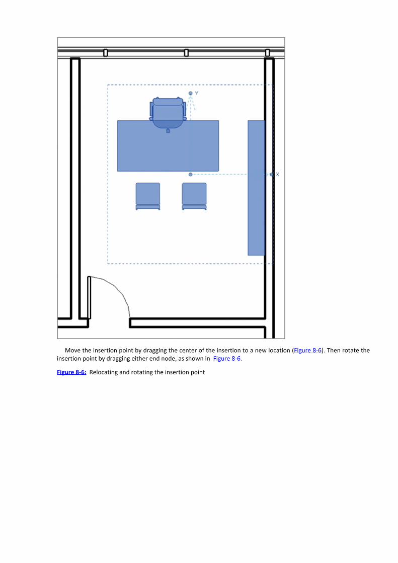
Move the insertion point by dragging the center of the insertion to a new location (Figure 8-6). Then rotate theinsertion point by dragging either end node, as shown in Figure 8-6.
Figure 8-6: Relocating and rotating the insertion point

Copying GroupsNow let’s copy this group to a few new locations. You have a couple of good options. If there’s already an instanceof the group in the view that you’re working in, select the group and then click Copy (highlighted on the left inFigure 8-7) or Create Similar (highlighted on the right).
Figure 8-7: The Copy and Create Similar tools
The other option you have is to drag an instance from the Project Browser just like any other element. Thegroup that we’ve just created is shown in Figure 8-8.
Figure 8-8: Our new group appears in the Project Browser.

Choose whichever option you like and copy the group around the floor plan as shown in Figure 8-9. You’ll alsoneed to rotate the copies in order to orient them properly.
Figure 8-9: Creating copies of groups
Duplicating GroupsIn many cases you’ll start with one group and then create permutations of that group as the design progresses.You can accomplish this easily by duplicating one of the groups in the Project Browser. Another useful option is toselect one of the groups that you want to edit and then duplicate it via the Edit Types dialog (Figure 8-10).
Figure 8-10: Duplicating the group

First, select the Office Furniture 1 group; then click Edit Type. Now you’ll be able to duplicate the group. Namethe new group Office Furniture 2. The new group will show up in the Project Browser (Figure 8-11).
Figure 8-11: The new group in the Project Browser, ready to be edited
Now let’s edit this new group.
Editing GroupsSelect the group shown in Figure 8-12. On the Group panel of the contextual Modify | Model Groups tab is theEdit Group option. Select this tool and you’ll enter Edit Group mode.
Figure 8-12: Selecting Edit Group mode
Everything in the group that you’re editing is now shown as usual, while everything not in the group is given atemporary sepia tone (see Figure 8-13).
Figure 8-13: In Edit Group mode, everything not in the group is given a temporary sepia tone.
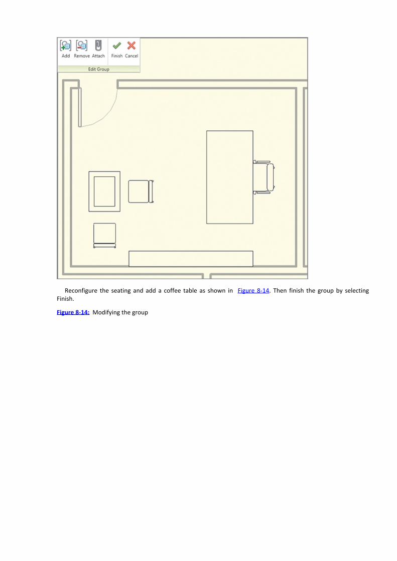
Reconfigure the seating and add a coffee table as shown in Figure 8-14. Then finish the group by selectingFinish.
Figure 8-14: Modifying the group

Now copy another instance of the group in your project, as shown in Figure 8-15. Keep in mind that with everycopy of a group, all your other project views and schedules will be updating in real time!
Figure 8-15: Copying the group

Exchanging GroupsAny group can be exchanged for any other group. Before you exchange one group for another, you may want tocheck that the insertion points of the two groups are properly located in order to keep the replaced group fromshifting its location.
To replace a group, select it and then click the pull-down menu in the Properties window. You’ll see all the othergroups in the same category. Model groups may contain geometry and datums, whereas Detail groups will onlycontain 2D elements like detail items. Exchange the group as shown in Figure 8-16.
Figure 8-16: Exchanging groups

Saving GroupsWith very large or complex groups, it may be helpful to work on them outside the project environment and thenreload them into your project. To save a group, select the group name from the Project Browser, right-click, andselect Save Group, as shown in Figure 8-17.
Figure 8-17: Saving the group

By default, you’ll then be prompted to save the group with the same name (Figure 8-18). The file is saved as aRevit project (*.rvt) and you can open the file and modify it as required.
Figure 8-18: Group saved with .rvt extension
Loading GroupsWhen you’re finished editing the group, you can easily reload it by selecting the group name, right-clicking, andchoosing Reload from the context menu (Figure 8-19).
Figure 8-19: Reloading the group
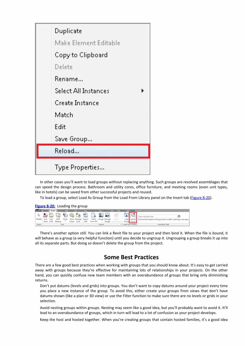
In other cases you’ll want to load groups without replacing anything. Such groups are resolved assemblages thatcan speed the design process. Bathroom and utility cores, office furniture, and meeting rooms (even unit types,like in hotels) can be saved from other successful projects and reused.
To load a group, select Load As Group from the Load From Library panel on the Insert tab (Figure 8-20).
Figure 8-20: Loading the group
There’s another option still. You can link a Revit file to your project and then bind it. When the file is bound, itwill behave as a group (a very helpful function) until you decide to ungroup it. Ungrouping a group breaks it up intoall its separate parts. But doing so doesn’t delete the group from the project.
Some Best PracticesThere are a few good best practices when working with groups that you should know about. It’s easy to get carriedaway with groups because they’re effective for maintaining lots of relationships in your projects. On the otherhand, you can quickly confuse new team members with an overabundance of groups that bring only diminishingreturns.
Don’t put datums (levels and grids) into groups. You don’t want to copy datums around your project every timeyou place a new instance of the group. To avoid this, either create your groups from views that don’t havedatums shown (like a plan or 3D view) or use the Filter function to make sure there are no levels or grids in yourselection.
Avoid nesting groups within groups. Nesting may seem like a good idea, but you’ll probably want to avoid it. It’lllead to an overabundance of groups, which in turn will lead to a lot of confusion as your project develops.
Keep the host and hosted together. When you’re creating groups that contain hosted families, it’s a good idea

to keep the host and hosted together. Otherwise, you have to remember to create the host on which one of thegrouped elements depends. Deleting the host (outside the group) that has a relationship to elements within thegroup can lead to project errors
Avoid attached relationships with walls. For example, if a wall is attached to a top level and then added to agroup, everything will be fine as long as all the levels are equally spaced. But if one of the levels moves, all theother walls in the group will try to update accordingly. Because the levels they’re associated to have not moved,you’ll get errors and strange wall overlaps.
Create left and right options when necessary. While mirroring CAD files (or even 3D components) seems fine inprinciple, a lot of content doesn’t get manufactured in left and right options. Unfortunately, content in Revitdoesn’t have an option to “disallow mirroring,” so if someone mirrors a component, it may look fine in the plan.But in reality, they’re indicating to another team member (like an engineer) that a piece of equipment is goingto be serviced on a side that doesn’t exist. For example, mirroring can put the hot water on the right and thecold on the left. So, we suggest you create left and right options. Yes, updating two options will take a bit moretime—but doing so will help you avoid expensive field changes that result from someone unknowingly mirroringfixtures, furniture, and equipment.
Using Phasing
Phasing allows your project to express the component of time. All project geometry has a phase component (whencreated and demolished). And all views have a component in order to allow you to filter within a specific range oftime. Let’s take the previous exercise and continue to create a phasing exercise. But if you haven’t finished theprevious exercise, you can start with the file 08_Groups_and_Phasing_Middle.rvt from the book’s web page.
Geometry PhasesFirst of all, let’s look at the phasing properties for some of the walls in the project. Select the wall, as shown Figure8-21. Note that there are properties for Phase Created and Phase Demolished. As a matter of fact, all the elementsin this file present when we first started this chapter (all the walls, doors, curtain walls, and so forth) were createdon the Existing phase. All the furniture and groups were placed on the Proposed phase. Imagine a scenario whereyou have an existing tenant space that is empty and needs to be configured for a new use, and you’ll get the ideaof where this exercise is headed.
Figure 8-21: Geometry phases

At the moment, there are only two phases in the project (Existing and Proposed), and these properties can beassigned to any geometry. Don’t worry about having a distinct Demolition phase, as demolition occurs duringeither Existing or Proposed.
View PhasesViews have phases as well. These phases allow you to filter views so that you can isolate geometry based on whenit’s created, demolished, or proposed. Figure 8-22 shows the present view phase of the Phase filter.
First of all, it’s important to note that the phase of the view is the same phase that will be assigned to thegeometry that you create in that view. So if View Phase is set to Existing, the geometry will be considered existing;if View Phase is set to Proposed, the geometry will be given the Proposed phase. But don’t worry if you get thiswrong or need to change a phase property later—this property is easily modified.
Figure 8-22: View phases
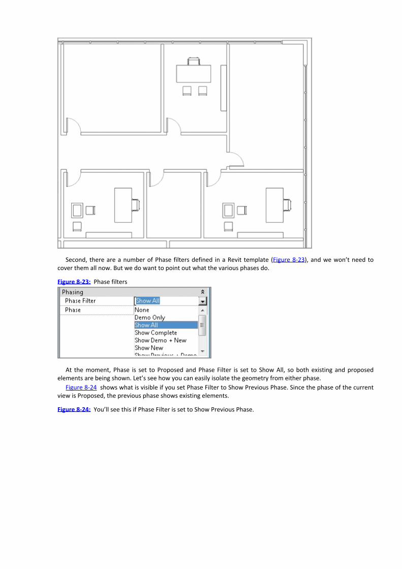
Second, there are a number of Phase filters defined in a Revit template (Figure 8-23), and we won’t need tocover them all now. But we do want to point out what the various phases do.
Figure 8-23: Phase filters
At the moment, Phase is set to Proposed and Phase Filter is set to Show All, so both existing and proposedelements are being shown. Let’s see how you can easily isolate the geometry from either phase.
Figure 8-24 shows what is visible if you set Phase Filter to Show Previous Phase. Since the phase of the currentview is Proposed, the previous phase shows existing elements.
Figure 8-24: You’ll see this if Phase Filter is set to Show Previous Phase.

Now select Show New. Now only the new, or proposed, elements are shown, as you can see in Figure 8-25.If you choose Previous + New, the existing and proposed elements will be shown (Figure 8-26).
Figure 8-25: Phase Filter set to Show New
Figure 8-26: Geometry phases

Now set the view back to Show All for the remaining exercises.
Demolition and Proposed ElementsAs part of this scenario, we’re going to turn these two separate tenant spaces into a single space. We’ll do so bydemolishing a few elements and adding proposed elements.
Start by selecting the Manage tab and clicking the Demolish tool in the Phasing panel (Figure 8-27). Now youcan demolish a few elements.
Figure 8-27: Demolition tool
Next, select the two doors and walls shown in Figure 8-28. Notice as you select the elements for demolitionthey’re given a dashed representation in plan (a common graphic convention to indicate demolition).
Figure 8-28: Demolished elements

If you look at the view in 3D, the demolished walls are indicated by a red color. And if you look closely, you’llnotice that Revit has replaced the demolished door with a new wall (Figure 8-29).
Figure 8-29: Demolished view in 3D
Now you need to reconfigure this office to accommodate passage to the other space. Start by moving thefurniture group to the right and add a new wall and door to complete the revised office space (Figure 8-30). Besure that the new walls have a height of 10ʹ to match the existing walls.
Figure 8-30: Proposed elements in 2D

You’ll notice that Revit has automatically demolished the portion of the existing wall that needs toaccommodate the proposed door (Figure 8-31).
Figure 8-31: Proposed elements in 3D
Finally, you need to use the Split Element tool to split the upper wall at the intersection of the new wall so youcan demolish only a portion of the existing wall (Figure 8-32).
Figure 8-32: Split Element tool
Split the wall at the location shown in Figure 8-33.
Figure 8-33: Splitting the wall

Now demolish the two left walls as shown in Figure 8-34. Note that the door (a hosted element) has beenautomatically demolished as well. This makes sense as the door would not be able to exist without the wall.
Figure 8-34: Demolishing the walls
Now split the lower wall as shown in Figure 8-35.
Figure 8-35: Splitting the lower wall
When using the phasing tools, you’ll often have to clean up wall conditions between the intersection of existingwalls that remain and their demolished walls. First, select the demolished wall. You’ll notice that blue nodesindicate each endpoint of the wall. By default, the wall attempts to automatically join the other walls.
To modify this condition, right-click on the blue node and select Disallow Join from the context menu (Figure 8-

36). Now you can drag the wall away from the undesirable joined condition. Once you do this the remaining wallswill join properly.
Repeat the process for all the intersections marked in Figure 8-37.
Figure 8-36: Splitting the wall
Figure 8-37: Cleaning wall joins
We think it’s a good idea to resolve wall joins periodically as you work, rather than put them off to do at the lastminute.
Completed ViewsNow go back to your 3D view and let’s see what the different stages of existing we need to complete look like.First, set Phase to Existing and Phase Filter to Show New. That way, you will see only the existing elements (beforeany demolition or proposed furniture), as shown in Figure 8-38.
Figure 8-38: Existing phase

Now set Phase to Proposed and Phase Filter to Show Previous + Demo. None of the proposed elements areshown, but the existing elements are displayed along with the elements that will be demolished (Figure 8-39).
Now set Phase Filter to Show Complete. The existing walls remain along with the newly proposed elements(Figure 8-40).
Figure 8-39: Existing and demolition shown
Figure 8-40: Show Complete filter


Chapter 9
Rooms and Color Fill Plans
The ability to add spaces to rooms has terrific implications. Keeping room names and areas coordinated freeshours of manual effort for more productive and meaningful design-related tasks. Once rooms are tagged, you’ll beable to create coordinated color fill plans that automatically reflect the data in the room’s space. Any changes tothe space are immediately reflected throughout the entire Revit project.
In this chapter, you learn the following skills:Tagging spaces with room tags
Creating room keys
Generating color fill room plans
Tagging Spaces with Room TagsStart by opening the Revit file that you completed at the end of Chapter 8, “Groups and Phasing.” If you haven’tyet completed the chapter, you can go to the book’s web page and download the Revit filec09_Rooms_and_Color_Fills_Start.rvt. Figure 9-1 shows a view of the Level 1 floor plan when you open thefile. Set the scale to 1⁄4ʺ = 1ʹ-0ʺ [1:50].
Figure 9-1: Level 1 floor plan

When you’ve finished the exercises in this chapter, you can inspect the file in its finished state on the book’sweb page at www.sybex.com/go/revit2012essentials. Download the file titledc09_Rooms_and_Color_Fills_Finish.rvt.
Room TagsRooms and room tags are two different things and the distinction is important. The room is the spatial object thatcontains all the metadata about the space. The tag merely reports those values. In many cases you can edit the tagand the room values will update (and vice versa). But whereas deleting the room will delete the tag, the oppositeis not true. You can delete a tag, and the room will remain. This makes sense, as the room will not be tagged in allviews.
To add a room to your project, select Room tool on the Room & Area palette of the Home tab. Two options areavailable: Room and Room Separation Line. Select the Room option.
Now the context menu that lets you modify and place rooms becomes available. As you hover over enclosedspaces, the room boundary will highlight, indicating the space you’re about to tag (Figure 9-2). You don’t have totag rooms as you place them, but by default this option is selected.

Figure 9-2: Adding a room and room tag
The tag that has been selected only indicates the room name and number (Figure 9-3), but more options areavailable. If you select the room tag and pull down the Properties menu for the tag, you’ll see that the same tagcontains several parameters.
Figure 9-3: Room tag
Select the Room Tag With Area option. Once the option is selected, the room tag will show the area based onyour project units (Figure 9-4). In this case, the room is 274 square feet. This feature is incredibly helpful if youwant to create rooms as your design develops that allow you to constantly confirm that your design programparameters are being maintained.
Figure 9-4: Room Tag With Area

Select the room and the properties for the space will display in the Properties Pallet. You can quickly and easilymodify both the room number and name here (Figure 9-5).
Figure 9-5: Changing the room number and name

Room BoundariesNow let’s see what happens if you move a wall that defines this space. Select the wall at the right as shown inFigure 9-6 and move it 2ʹ [600 mm]. The moment that you release the wall, the space updates with the newinformation, which is immediately reported by the room tag (Figure 9-7).
Figure 9-6: Moving the wall

Figure 9-7: Updated room space and tag
Let’s continue to add spaces and tags as shown in Figure 9-8.
Figure 9-8: Adding rooms and tags
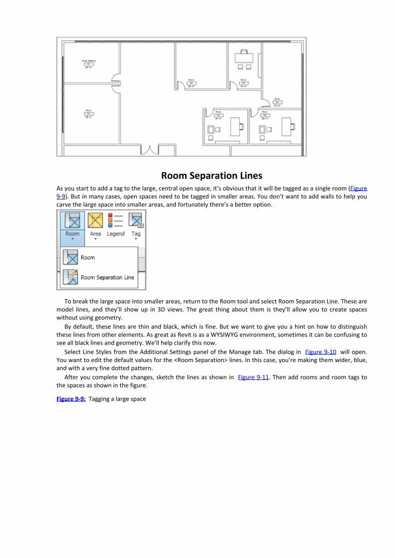
Room Separation LinesAs you start to add a tag to the large, central open space, it’s obvious that it will be tagged as a single room (Figure9-9). But in many cases, open spaces need to be tagged in smaller areas. You don’t want to add walls to help youcarve the large space into smaller areas, and fortunately there’s a better option.
To break the large space into smaller areas, return to the Room tool and select Room Separation Line. These aremodel lines, and they’ll show up in 3D views. The great thing about them is they’ll allow you to create spaceswithout using geometry.
By default, these lines are thin and black, which is fine. But we want to give you a hint on how to distinguishthese lines from other elements. As great as Revit is as a WYSIWYG environment, sometimes it can be confusing tosee all black lines and geometry. We’ll help clarify this now.
Select Line Styles from the Additional Settings panel of the Manage tab. The dialog in Figure 9-10 will open.You want to edit the default values for the <Room Separation> lines. In this case, you’re making them wider, blue,and with a very fine dotted pattern.
After you complete the changes, sketch the lines as shown in Figure 9-11. Then add rooms and room tags tothe spaces as shown in the figure.
Figure 9-9: Tagging a large space

Figure 9-10: Editing room separation line properties
Figure 9-11: Adding room separation lines

Creating Room KeysYou could certainly continue editing all the room names manually (and this is regularly done during early design).But in many cases—and particularly on larger projects—the program is very specific about room names and othervalues given to spaces. Another factor is that rooms are often identically and repeatedly named. If multiple roomnames need to be edited, this can be a time-consuming and tedious process.
A better option is to quickly create a room key. This key will contain all the values for the rooms in your roomprogram. The key value is then associated to one or many rooms. And in the event of a change, you only need toedit the value in the key, and all the rooms update instantly.
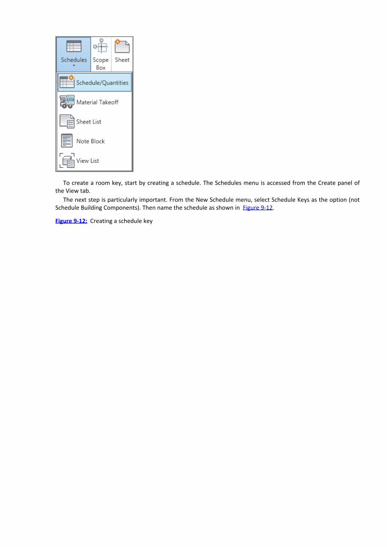
To create a room key, start by creating a schedule. The Schedules menu is accessed from the Create panel ofthe View tab.
The next step is particularly important. From the New Schedule menu, select Schedule Keys as the option (notSchedule Building Components). Then name the schedule as shown in Figure 9-12.
Figure 9-12: Creating a schedule key

The Key Name field is already selected by default. The only other field you want to add is Name, which willcontain the name of the room in the key (Figure 9-13). When you finish the dialog by clicking OK, nothing willschedule and you’ll have no line items. This is because you didn’t create a schedule; you created a schedule key.You’ll add the key fields in the next step.
Figure 9-13: Adding fields to the room key

Creating Key Fields
From the Rows panel on the context menu, select the New option. Now you can add rows to your schedule key.Add a total of six rows.
At this point, you can edit the fields in the schedule key as shown in Figure 9-14. The key description will notshow up in your room tag. (Hint: Use a real-world description that helps the design team understand the contextof the tag beyond a one-word name.) Finally, add numbers to the prefix of the key descriptions as an orderingdevice.
Figure 9-14: Room name key
Now go back to the Floor plan view of Level 1, select the room, and assign a key value from the Room Styledrop-down. You’ll see something like Figure 9-15.
Figure 9-15: Assigning a key value to the room
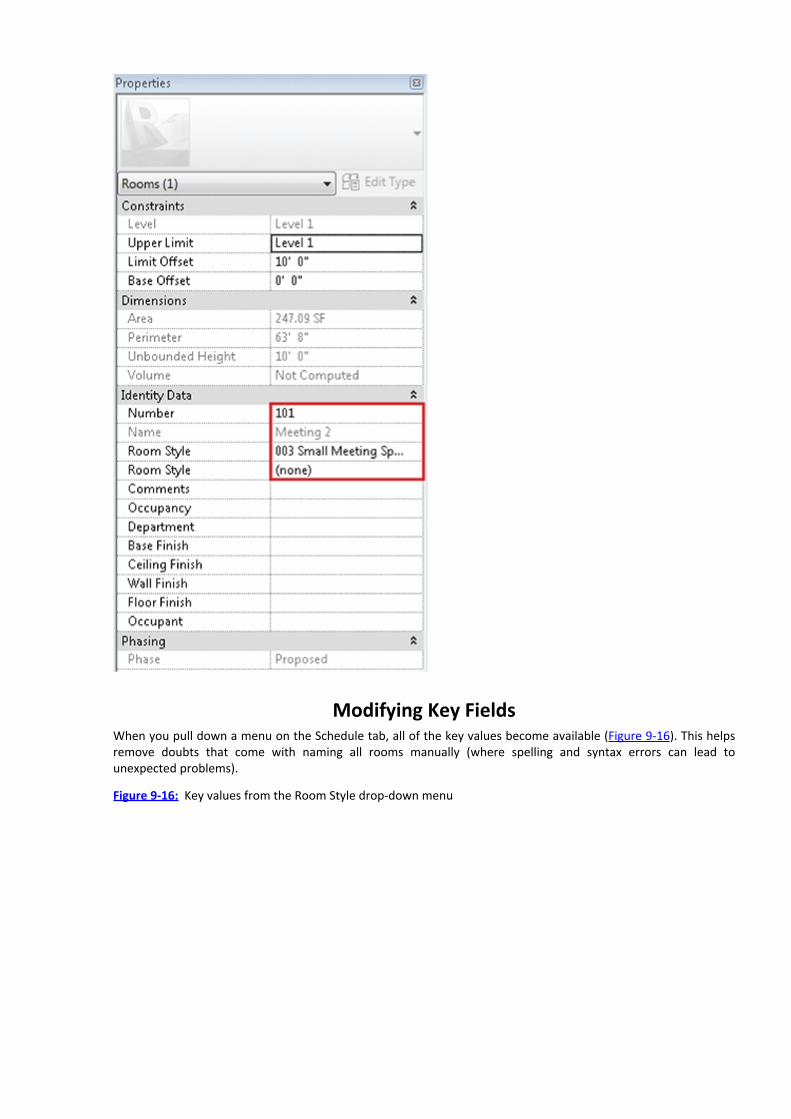
Modifying Key FieldsWhen you pull down a menu on the Schedule tab, all of the key values become available (Figure 9-16). This helpsremove doubts that come with naming all rooms manually (where spelling and syntax errors can lead tounexpected problems).
Figure 9-16: Key values from the Room Style drop-down menu

The great thing about this is that if the room names need to change, you only need change them in onelocation—the room key. In Figure 9-17, we’ve changed the Name fields for Office 1 and Office 2. This change isimmediately reflected throughout the project.
Figure 9-17: Updating the room key
Generating Color Fill Room Plans
Creating color fill plans in Revit is easy to do and once again, color fill plans constantly update as existinginformation is modified or new information is added. This allows you to focus on communicating rather thancoordinating your design information—as if resolving your design isn’t already hard enough!
Adding a Color Legend

To create a color fill plan, select the Room And Area panel of the Home tab, and then select the Legend tool. Placethe start location for the legend as shown in Figure 9-18. You’ll then be shown a dialog that allows you to selectthe space type and color scheme. In this case you’re creating a Room type with a color scheme based on the nameof the space.
Figure 9-18: Defining the space type and color
Keep in mind that these values don’t have to exactly correspond. For example, you could show room names inthe tag, while the color fill illustrated the department or other value of the space in the fill plan.
Once these values are defined, the color fill is automatically generated. And by default, only the values in theview are indicated. For example, if you had many more room styles in the project but not in the view, this couldget confusing. The default parameter is to only create colors for values that are shown (Figure 9-19).
Figure 9-19: Updating the room Legend
To edit the default color assignments, select the color fill legend in the plan view. You’ll then be able to selectthe Edit Scheme tool from the Scheme panel in the context menu.
Selecting the Edit Scheme tool opens the Edit Color Scheme dialog. All the values are available for editing(Figure 9-20). You can edit the color as well as the fill pattern. Doing so is helpful if you want to create an analyticfill pattern for a black and white or grayscale print.
Figure 9-20: Edit Color Scheme dialog

Modifying Color LegendsLet’s edit the color of the Circulation fill. Select the Color field and another dialog will open. Modify the values to R255, G 128, and B 128. When you complete the changes, Revit automatically updates the fill color to reflect yourchanges (Figure 9-21).
Figure 9-21: Resulting color fill
As you can tell, Revit created a color fill in the project view based on all the room names that were assigned tothat view. So what would happen if you created a new room? Well, let’s find out.
Start by modifying the room key as shown in Figure 9-22. In this scenario, you’re adding a new style toaccommodate a director’s office. Just add another field to the key and then edit as shown.
Figure 9-22: Adding a new key value
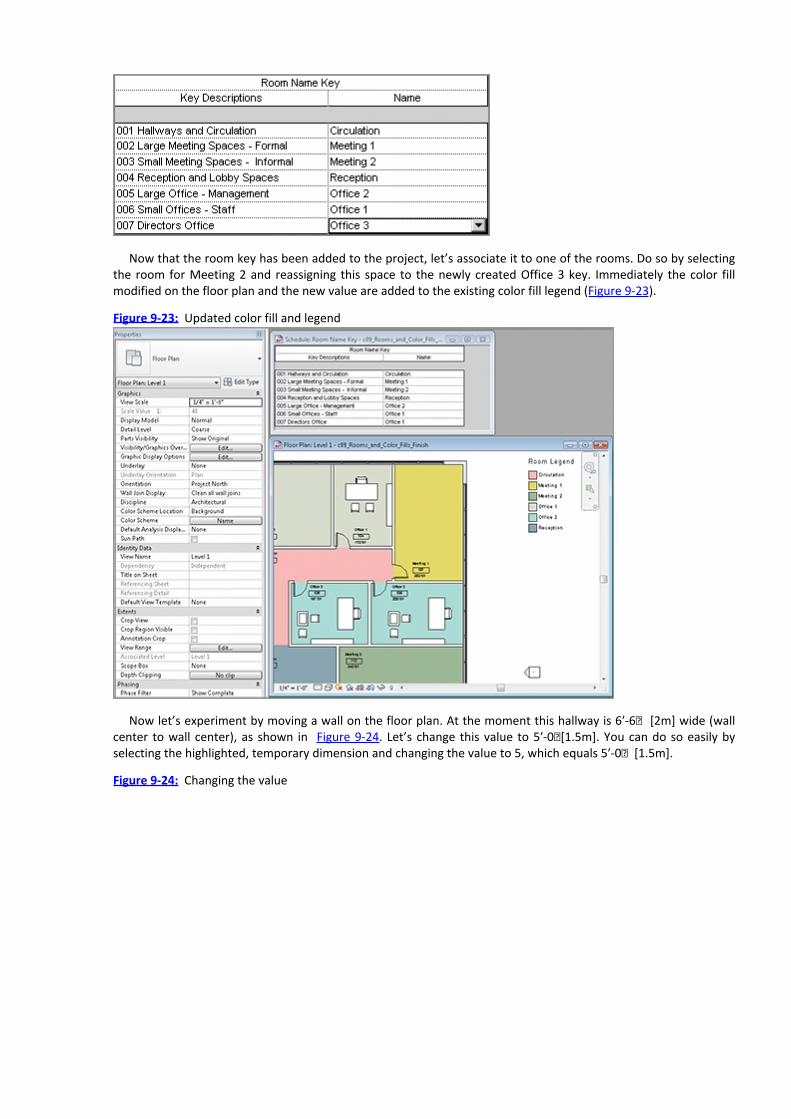
Now that the room key has been added to the project, let’s associate it to one of the rooms. Do so by selectingthe room for Meeting 2 and reassigning this space to the newly created Office 3 key. Immediately the color fillmodified on the floor plan and the new value are added to the existing color fill legend (Figure 9-23).
Figure 9-23: Updated color fill and legend
Now let’s experiment by moving a wall on the floor plan. At the moment this hallway is 6ʹ-6ʺ [2m] wide (wallcenter to wall center), as shown in Figure 9-24. Let’s change this value to 5ʹ-0ʺ[1.5m]. You can do so easily byselecting the highlighted, temporary dimension and changing the value to 5, which equals 5ʹ-0ʺ [1.5m].
Figure 9-24: Changing the value

The room tags immediately update to reflect their new area and the color fills update to reflect their newboundary condition (Figure 9-25).
Let’s take this exercise one step further. Room information in section is incredibly helpful for communicatingyour design intent.
Figure 9-25: Updated color fill
Adding Tags and Fill Colors in SectionWe’ll start by creating a section across the project plan view (Figure 9-26). Then double-click the section head toopen the new view.
Figure 9-26: Creating the building section

Figure 9-27 illustrates the new building section. While all the geometry is shown correctly, it would certainlyhelp to tag the spaces with their room names.
Figure 9-27: Resulting building section
You have two options to tag the room spaces. If you select Room Tag, you’ll be able to place each tag manually.This approach is fine for a small project, but on a larger project it would take a considerable amount of time.
For this exercise, let’s select Tag All Not Tagged. Selecting this option will open allow you to tag numerouselement categories in a view all at once. But you only need to tag rooms. Select the Room Tags category as shownin Figure 9-28. Then click OK.
Immediately the view is populated with room tags (Figure 9-29). Keep in mind that Revit will center the tags inthe room, so you will need to move their location slightly if the tag is overlapping geometry and unclear.
So what about color fills? Well, let’s find out. Select the Legend tool and place the legend in the section view.The rooms are immediately filled with the same pattern and color in section as the color fill in plan (although thisdoesn’t have to be the case), as shown in Figure 9-30. Again, there’s no reason the fill in section couldn’t describeDepartment or other values, while the room tags displayed the room name.
Figure 9-28: Adding room tags to the section view


Chapter 10
Worksharing
Understanding multiuser workflow is essential to completing your pilot project in Revit. There’s plenty of work togo around between the design, development, and eventual documentation of a building project.
If you’ve never used Revit before, what you’re probably used to is CAD. Multiuser workflow in CAD is a verydifferent animal, so you may need to suspend your expectations of what it’ll be like in Revit.
Whereas CAD projects are typically divided along the lines about what needs to be drawn (plan, section,elevation at various levels of detail), Revit envelops you in the entire process. 2D, 3D, schedules, and so on are in asingle database waiting for the input and direction of your team.
The great thing is that this is a far more elegant and efficient process than manually managing 2D files (whichonly one person can work on at a time). If anything, expect a large CAD-based project that would require 5–6 staffworking in CAD to require about half that number working in Revit.
In this chapter, you learn the following skills:Enabling worksharing
Creating central and local files
Adding worksets
Assigning elements to worksets
Saving to the central file
Creating new elements
Using workset display filters
Using worksharing to work with consultants
Using guidelines for worksharing
Enabling Worksharing
The first thing that you’ll need to do is open the file from the end of Chapter 9, “Rooms and Color Fill Plans.” If youdon’t have the file, go to the book’s web page at www.sybex.com/go/revit2012essentials and downloadc10_Worksharing_Start.rvt.
Saving the FileWe’d strongly suggest that before you enable worksharing, you create a new copy of the file in order to back upyour old work. For example, you may have been doing some schematic design planning in Revit and now it’s timeto add more people to the project in order to meet a deadline. Creating a copy of your old file (before enablingworksharing) is just good practice in case you need to return to your previous work.
In this case, we’re preparing for this file to be the central file by naming it c10_Worksharing_Central.rvt(Figure 10-1).
Figure 10-1: Saving a copy of the file

Once the file is open, go to the Collaborate tab. The tool to enable and access worksets is on the Worksetspalette of the Collaborate tab.
When you select the Worksets tool, the following dialog box appears telling you three important things:Worksharing can’t be undone (aren’t you glad you saved a copy?).
Datum is moving to a workset called Shared Levels and Grids.
Project content that is not view specific (geometry and rooms) is all being assigned to Workset1.
All of this is fine and will allow you to enable worksharing. Click OK to continue (Figure 10-2).
Figure 10-2: The initial worksharing dialog box
Next the dialog box shown in Figure 10-3 will display. Your workset username will appear in the Owner field. Atpresent, you own everything in the project. No one else can work on the project without your permission.
Figure 10-3: Worksets dialog box

Creating Central and Local FilesIf this were a real project, you would likely want to save the central file on a local server so that your other teammembers can have access to the file. They’re not going to work directly in the central file, but they’ll need to haveaccess to it in order to make their own local copies, and so that those local copies can communicate to the centralfile from a central location.
Creating the Central FileIt’s a good idea to save the project, which will establish it as the central file (Figure 10-4). Select the desiredlocation for the central file. Be aware that you can’t just move it after the fact. It’s a bit more complicated, becausemoving a central file will create a local copy. We don’t want to get into all the details now—just know that youwant to save the file in the desired location.
Now close the central file and let’s create our local copy.
Figure 10-4: Saving the central file
Creating the Local File
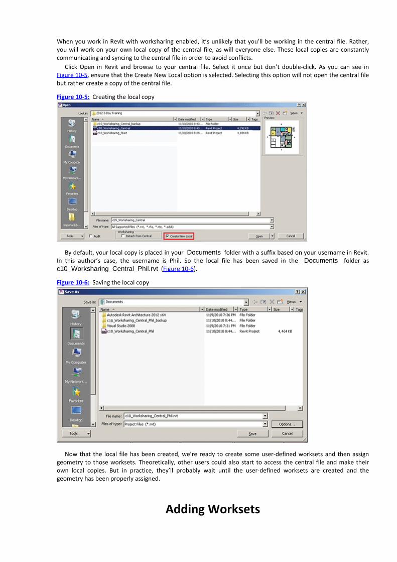
When you work in Revit with worksharing enabled, it’s unlikely that you’ll be working in the central file. Rather,you will work on your own local copy of the central file, as will everyone else. These local copies are constantlycommunicating and syncing to the central file in order to avoid conflicts.
Click Open in Revit and browse to your central file. Select it once but don’t double-click. As you can see inFigure 10-5, ensure that the Create New Local option is selected. Selecting this option will not open the central filebut rather create a copy of the central file.
Figure 10-5: Creating the local copy
By default, your local copy is placed in your Documents folder with a suffix based on your username in Revit.In this author’s case, the username is Phil. So the local file has been saved in the Documents folder asc10_Worksharing_Central_Phil.rvt (Figure 10-6).
Figure 10-6: Saving the local copy
Now that the local file has been created, we’re ready to create some user-defined worksets and then assigngeometry to those worksets. Theoretically, other users could also start to access the central file and make theirown local copies. But in practice, they’ll probably wait until the user-defined worksets are created and thegeometry has been properly assigned.
Adding Worksets

Open the Worksets dialog box by using the same Workset tool we used to activate worksharing previously. ClickNew and then create three additional worksets, as shown in Figure 10-7. Keep in mind that worksets are not“layers” and a lot of granularity isn’t required. Basically worksets are for broad collections of objects based on theirrelationship to the project.
The project that we’re using for this exercise is fairly modest. Interior, exterior, and core worksets are sufficient.If this were a multistory project, you would likely create interior worksets for each building level, as well as anotherworkset for the roof and roof-related elements (such as equipment and skylights). Once you’ve created theworksets, click OK.
Figure 10-7: Creating additional worksets
Now let’s open the Visibility/Graphic Overrides dialog box for the view (press VG on the keyboard). As you cansee in Figure 10-8, there’s an additional tab for worksets. This tab didn’t exist before worksharing was enabled.This tab allows you to turn off elements based on their workset assignment.
Figure 10-8: The Worksets tab
Workset VisibilityYou’re about to begin assigning portions of the project to your user-defined worksets. As you do this, you want to

be able to clear the view of elements that have already been assigned to one of your newly created worksets.Basically, you want to work “subtractively” by removing elements.
To do this, set the Visibility Setting column for the active view to Hide, as shown in Figure 10-8. As geometry isassigned to each of those worksets, it will disappear from view and keep you from accidentally selecting it again.
By the way, don’t delete Workset1 from your project. It’s a great place to put content when you’re not surewhich workset something is supposed to belong to. Also, we’ve encountered many projects that midstream wereintroduced to staff who had minimal Revit experience. Rather than have them obsess over which workset shouldbe active as they work, we told them to put all their work in Workset1 and that we’d move things around later.This also helped us isolate and review their work.
Now you can begin assigning elements to your user-defined worksets.
Assigning Elements to WorksetsAssigning elements to worksets is easily done. Just be sure of what you’re selecting. You will often use the Filtertool and may work in more than one view. Except for rooms, it’s often easier to select elements in 3D views. Butfor this exercise, we’ll keep it simple by working from the 2D Level 1 floor plan view.
Start by selecting the elements shown in Figure 10-9:—the walls in the lower-left corner of the plan.
Figure 10-9: Assigning user-defined worksets
On the Properties palette you’ll now see a field that indicates the workset assignment. Change this value fromWorkset1 to Core. Once you do so, the elements assigned to the core workset will no longer be visible in this view.Don’t be alarmed! If you’ll recall from the previous step, we turned off the visibility for this (and other) worksets,so this should be expected.

Now let’s select all the interior elements and move them all to a new workset rather than selecting one elementat a time. To select all the elements described, draw a selection window starting at the lower right to the upperleft inside the exterior walls. Windowing from this direction will include every element you’ve crossed or includedwithin the window you drew. Should you have windowed left to right, it would have selected only the elementsthat were fully contained within the selection box.
All of the selected elements can’t be assigned to user-defined worksets, so you’ll need to use the Filter tool todeselect some of the elements you’ve selected. Click the Filter tool from the Modify menu. In the Filter dialog box,deselect Room Tags and Views, as shown in Figure 10-10.
Figure 10-10: Deselecting elements with the Filter tool

Now assign these elements to the interior workset. Once again, don’t be alarmed when those elements seem todisappear.
For the final selection, select all the remaining walls that are visible in the view and then select the Filter toolagain. This time, only select Walls in the Category list (Figure 10-11). Elements like curtain panels, grids, andmullions automatically belong to their parent workset of walls.
Now all the geometry and rooms will not be visible in your project. So open the Visibility/Graphic Overridesdialog box for the view and reset the visibility settings as shown in Figure 10-12. All the elements will once againbe visible in your view. At this point, you can save your project and synchronize it with the central file.
Figure 10-11: Isolating walls with the Filter tool
Figure 10-12: Resetting the visibility settings

Saving to the Central File
When you want to save your work to the central file, there are a number of options to fit your workflow. On theSynchronize panel of the Collaborate tab, you can click Synchronize With Central to see the first two ways to save:Synchronize And Modify Settings and Synchronize Now.
Synchronize And Modify Settings is a more explicit process by way of the dialog box shown in Figure 10-13,which gives you options to relinquish worksets, compact the central file, and save your local file after the sync withthe central file is complete.
Figure 10-13: Synchronize And Modify Settings
The Synchronize Now option is probably the more frequently used option. Consider creating a keyboardshortcut so you don’t have to return to this tab as you work and want to save to Central. This option will save yourlocal copy and sync with the central file as well as update your file with any changes from the central file. Anyborrowed elements are also relinquished. But if you have any workset checked out or editable, it’s not checkedback in. It will still be editable by you.
The Reload Latest option allows you to reload the latest version of the central file in your local project.However, it doesn’t publish any of your work in the central file.
Finally, the Relinquish All Mine option allows you to check back in elements that you may have borrowed butnot changed. If you’ve made changes, you either have to sync them with the central file or discard the changeswithout saving. You cannot relinquish elements in a file that has been modified.
So what do you do if you’ve made changes that you want to get rid of? The only way to do this is to close thefile and select the Do Not Save The Project option (Figure 10-14). This will close the project without saving yourwork or syncing with the central file.
Figure 10-14: Closing the file without saving changes

If you select this option, Revit will ask you what to do with the elements that you’ve borrowed or worksets thatyou have enabled (Figure 10-15). If you relinquish the elements and worksets, other people will be able to modifythem in their local files. If you keep ownership, the changes you’ve made will be lost, but you’ll still have theelements and worksets enabled.
Figure 10-15: Relinquishing elements and worksets
When you have no elements or worksets enabled in a project, you can confirm this by opening the Worksetsdialog box in Figure 10-16.
Let’s continue by adding new elements to our local file.
Figure 10-16: Relinquished elements and worksets

Creating New ElementsWhen worksharing is enabled, you’ll want to make sure that any new geometry or rooms you’re adding are beingassigned to the right workset. You’re going to add some new furniture to the project, so you’ll want to make theinterior workset active.
First let’s copy a group of furniture from room 105 to room 103, as shown in Figure 10-17. Since the activeworkset is interior, the elements in the group are assigned to this workset.
Figure 10-17: Copying a group
It’s not possible to have elements in a workset assigned to a different workset as the group. Revit automaticallyassigns the elements within a workset to the same workset as the group.
Now let’s duplicate an existing component and create a new type, and then use this new type in our project.

Start by duplicating the table. In the Project Browser, right-click 72ʺ×30ʺ [180cm×75cm] and choose Duplicatefrom the context menu (Figure 10-18).
Figure 10-18: Duplicating an existing type
Next, modify the duplicated table. Select the table again in the Project Browser, right-click, and choose TypeProperties.
Rename the type to 144ʺx 48ʺ[350cm x 120cm] using the Rename button. Next, modify the dimensionalparameters as shown in Figure 10-19, changing the Height, Length, and Width values. This will create asignificantly larger table for use in our conference rooms. Click OK to finish editing the family.
Figure 10-19: Modifying the type parameters

Now you can place a new instance of the table in our project (Figure 10-20). Again, since interior is the activeworkset, the table has been assigned accordingly. Place chairs around the table, as shown in Figure 10-21.
Figure 10-20: Adding the table to the project

Figure 10-21: Adding chairs to the table
This grouping of furniture will be a useful addition to other meeting spaces in our project. But rather than copythem around as separate elements, it’ll be more helpful to create a group and then copy this group in the project.
Select all the elements and then select the Group tool. Name the model group Large Table and Chairs. Click OK.Note that the group has also been assigned to the active workset (Figure 10-22).
Figure 10-22: Workset assignment for the new group
Opening and Closing WorksetsAs you work on larger and larger projects (of even very dense small projects), worksets are a great way to help youisolate and focus on what you’re trying to accomplish. And while each view has its own visibility settings, when youwant to isolate (or hide) elements throughout your project, worksets offer helpful options.
Open your Worksets dialog box and you’ll notice that at the moment all the user-created worksets are set toOpened. This is fine if you need to see everything at once. But for larger projects or in cases where you want tolimit what you’re seeing across all project views, you can selectively open and close worksets. Do so now and clickOK to close the dialog box.
The results are immediate (Figure 10-23). Only the interior workset is shown in all your project views (3D,perspective, plan, elevation, section, etc.).
Now that you have a good understanding of how to place elements on an active workset as well as open andclose worksets selectively, let’s explore workset display filters.
Figure 10-23: Interior workset isolated

Using Workset Display FiltersWorkset filters are new to Revit 2012 and are a great way for visually understanding many things about yourproject. To create this scenario, all three authors are accessing this file at the same time. There’s a central file onthe server and we’re all working from our local copies.
Furthermore, all of us have borrowed elements in the central file. In the past, who had ownership of certainelements was difficult to see, and this issue often created workflow problems when borrowed elements weremodified.
In Figure 10-24, you can see in the Worksets dialog box that no worksets are editable but that other users haveborrowed elements.
Figure 10-24: Borrowed elements in the Worksets dialog box
Now let’s look at the worksharing display options settings, which are available from the lower portion of the
Revit project window . Select the Settings option.Figure 10-25 illustrates the four sets of settings available for worksharing display in our project: Ownership
Status, Individual Owners, Updates, and Worksets. Notice that the settings are based on the particular parametersin our project (number of worksets, active users, and so forth). Let’s make some of these options active one at atime and view the results. Start with the Ownership Status tab. Ownership status helps you distinguish betweenelements that are owned by you, others, or no one.
Figure 10-25: Ownership Status visibility

To activate any of these settings, click the icon and choose one of the menu items from the list. Doing so willtoggle your visibility settings and apply an orange border to the view you’re in, alerting you that you’ve engagedthe settings. To turn them back off, choose the Worksharing Display Off option. Individual owners will help youvisualize exactly which elements belong to which users (Figure 10-26).
Finally, the Workset Assignments tab helps you visualize elements based on the workset to which they’reassociated (Figure 10-27).
We’re really glad these worksharing improvements have made it into Revit!
Figure 10-26: Individual Owners
Figure 10-27: Workset visibility
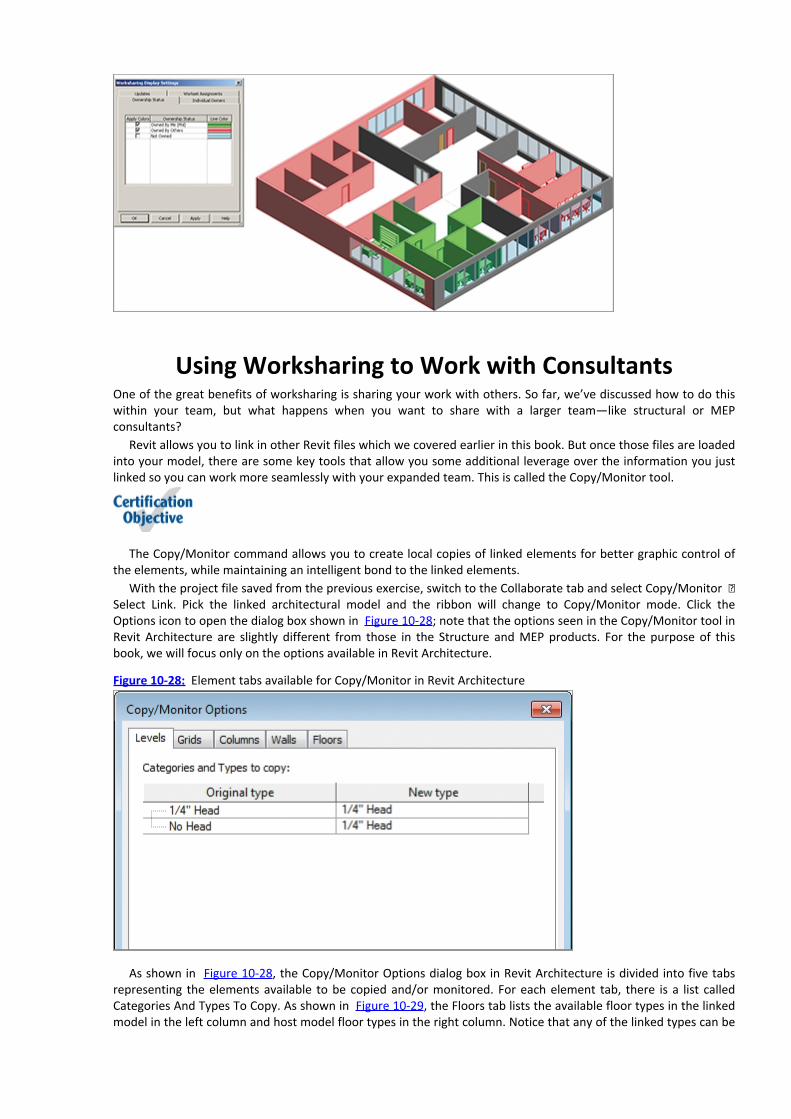
Using Worksharing to Work with ConsultantsOne of the great benefits of worksharing is sharing your work with others. So far, we’ve discussed how to do thiswithin your team, but what happens when you want to share with a larger team—like structural or MEPconsultants?
Revit allows you to link in other Revit files which we covered earlier in this book. But once those files are loadedinto your model, there are some key tools that allow you some additional leverage over the information you justlinked so you can work more seamlessly with your expanded team. This is called the Copy/Monitor tool.
The Copy/Monitor command allows you to create local copies of linked elements for better graphic control ofthe elements, while maintaining an intelligent bond to the linked elements.
With the project file saved from the previous exercise, switch to the Collaborate tab and select Copy/Monitor ⇒Select Link. Pick the linked architectural model and the ribbon will change to Copy/Monitor mode. Click theOptions icon to open the dialog box shown in Figure 10-28; note that the options seen in the Copy/Monitor tool inRevit Architecture are slightly different from those in the Structure and MEP products. For the purpose of thisbook, we will focus only on the options available in Revit Architecture.
Figure 10-28: Element tabs available for Copy/Monitor in Revit Architecture
As shown in Figure 10-28, the Copy/Monitor Options dialog box in Revit Architecture is divided into five tabsrepresenting the elements available to be copied and/or monitored. For each element tab, there is a list calledCategories And Types To Copy. As shown in Figure 10-29, the Floors tab lists the available floor types in the linkedmodel in the left column and host model floor types in the right column. Notice that any of the linked types can be
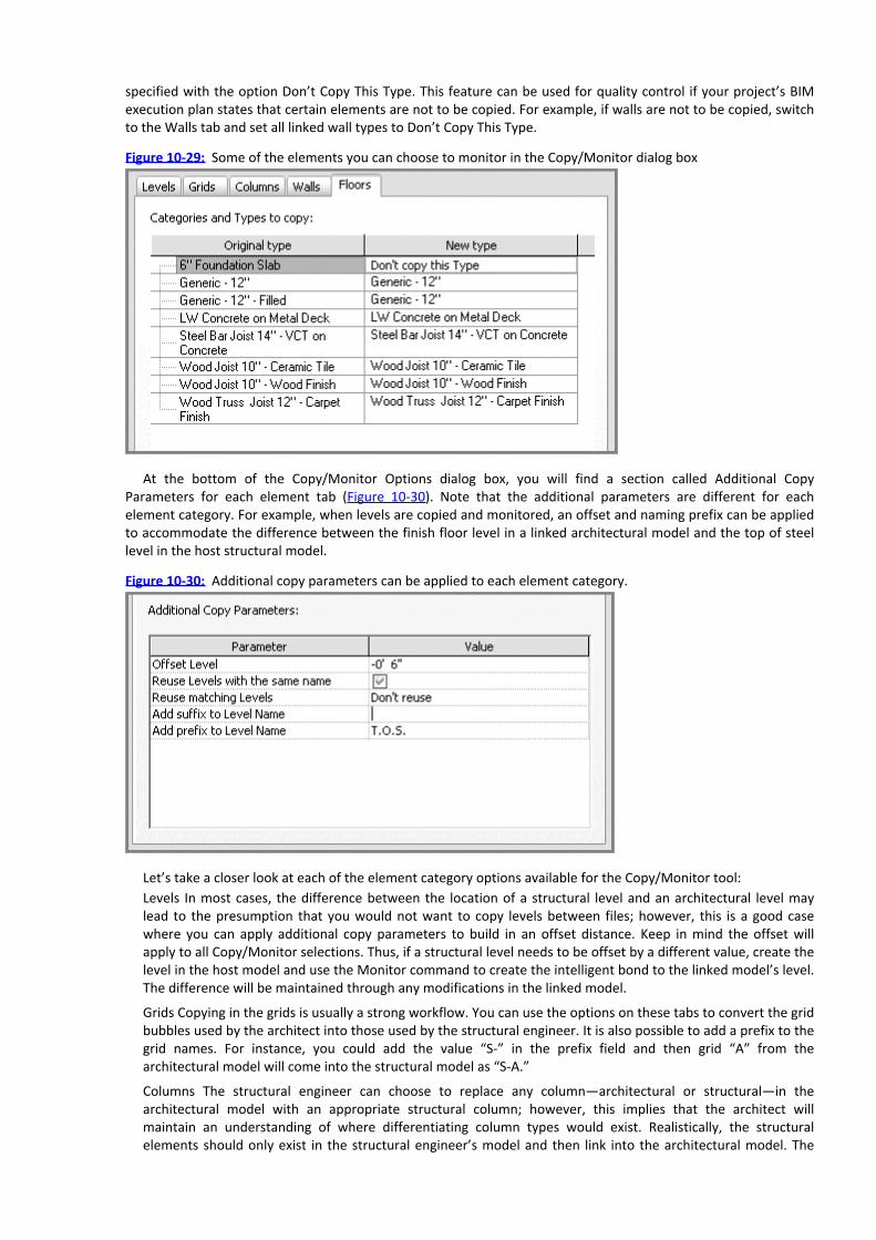
specified with the option Don’t Copy This Type. This feature can be used for quality control if your project’s BIMexecution plan states that certain elements are not to be copied. For example, if walls are not to be copied, switchto the Walls tab and set all linked wall types to Don’t Copy This Type.
Figure 10-29: Some of the elements you can choose to monitor in the Copy/Monitor dialog box
At the bottom of the Copy/Monitor Options dialog box, you will find a section called Additional CopyParameters for each element tab (Figure 10-30). Note that the additional parameters are different for eachelement category. For example, when levels are copied and monitored, an offset and naming prefix can be appliedto accommodate the difference between the finish floor level in a linked architectural model and the top of steellevel in the host structural model.
Figure 10-30: Additional copy parameters can be applied to each element category.
Let’s take a closer look at each of the element category options available for the Copy/Monitor tool:Levels In most cases, the difference between the location of a structural level and an architectural level maylead to the presumption that you would not want to copy levels between files; however, this is a good casewhere you can apply additional copy parameters to build in an offset distance. Keep in mind the offset willapply to all Copy/Monitor selections. Thus, if a structural level needs to be offset by a different value, create thelevel in the host model and use the Monitor command to create the intelligent bond to the linked model’s level.The difference will be maintained through any modifications in the linked model.
Grids Copying in the grids is usually a strong workflow. You can use the options on these tabs to convert the gridbubbles used by the architect into those used by the structural engineer. It is also possible to add a prefix to thegrid names. For instance, you could add the value “S-” in the prefix field and then grid “A” from thearchitectural model will come into the structural model as “S-A.”
Columns The structural engineer can choose to replace any column—architectural or structural—in thearchitectural model with an appropriate structural column; however, this implies that the architect willmaintain an understanding of where differentiating column types would exist. Realistically, the structuralelements should only exist in the structural engineer’s model and then link into the architectural model. The


Chapter 11
Details and Annotations
As you’ve seen so far, you can use Revit to create walls, doors, roofs, and floors; to define space; and to bring yourarchitectural ideas into three-dimensional form. In each of these cases, the geometry is typically modeled basedon a design intent, meaning that your goal isn’t to model everything but enough to demonstrate what the buildingis going to look like. To this end, it becomes necessary to embellish parts of the model or specific views withdetailed information to help clarify what you’ve drawn. This embellishment takes the shape of 2D detail elementsin Revit that you will use to augment views and add extra information.
In this chapter, you learn the following skills:Creating details
Annotating your details
Legends
Creating DetailsEven when you’re creating details, Revit provides a variety of parametric tools that allow you to leverage workingin a BIM model. You can use these tools to create strictly 2D geometry or to augment details you’re trying tocreate from 3D plans, sections, or callouts. To become truly efficient at using Revit to create the drawingsnecessary to both design and document your project, you must become acquainted with these tools—you’ll findyourself using them over and over again throughout your project.
All of these view-based tools are located on the Detail panel of the Annotate tab (Figure 11-1). This small butvery potent toolbox is what you will need to familiarize yourself with in order to create a majority of the 2Dlinework and components that will become the details in your project. To better understand how these tools areused, let’s quickly step through each of them.
Figure 11-1: The Detail panel of the Annotate tab
Detail Line
The Detail Line tool is the first tool located on the Detail panel of the Annotate tab. This tool is the closest thingyou’ll find to CAD drafting. It allows you to create view-specific linework using different lineweights, tools fordrawing different line shapes, and many of the same manipulation commands you would find in a CAD program.
Detail lines are view specific—they will only appear in the view in which they’re drawn. They also have anarrangement to their placement, meaning that you can layer them underneath or on top of other objects. Thisfeature is especially important when you begin using regions, detail lines, and model content to create yourdetails.

Using the Detail Line tool is fairly easy. Selecting the tool will change your ribbon tab to look like Figure 11-2.This new tab will have several panels that allow you to add and manipulate linework.
Figure 11-2: The Detail Line toolset
This new tab contains three panels: Modify, Draw, and Line Style. The Modify panel has the host of tools you’veused so far for your walls, doors, and other elements. Here you can copy, offset, move, and perform other tasks.The Draw panel allows you to create new content and define shapes, and the Line Style drop-down allows you tochoose the line style you’d like to draw with.
Regions
The next tool on the Detail panel of the Annotate tab is the Region tool. Regions are areas of any shape or sizethat you can fill with a pattern. This pattern (much like a hatch in AutoCAD) will dynamically resize with the regionboundary. Regions layer just like detail lines do and can be placed on top of, or behind, linework and modelobjects. Regions also have an opacity and can be completely opaque (covering what they are placed on) ortransparent (letting the elements show through).
There are two types of regions: filled regions and masking regions. Filled regions allow you to choose from avariety of hatch patterns to fill the region. They are commonly used in details to show things like rigid insulation,concrete, plywood, and other material types. Masking regions, on the other hand, come in only one flavor. Theyare white boxes that can have (or not have) discernable borders to them. Masking regions are typically used to“hide” or mask certain content from a view that you don’t want shown or printed.
ComponentsThe Component drop-down menu allows you to insert a wide array of component types into your model. Theseare 2D detail components, or collections of detail components in the case of a repeating detail. Detail componentsare schedulable, taggable, keynotable 2D families that allow an additional level of standardization within yourmodel. Some examples of when you’d use detail components are blocking in section, steel shapes, and metal studsin plan or section—just about any replicated 2D element that comes in a standardized shape.
Detail ComponentsDetail components are 2D families that can be made into parametric content. In other words, a full range ofshapes can be available in a single detail component. Because they are families, they can also be stored in youroffice library and shared easily across projects.

To add a detail component to your drawing, select Detail Component from the Component drop-down listlocated on the Annotate tab and use the Type Selector to choose from ones that are already inserted into themodel. If you don’t see a detail component you want to insert in the Type Selector, click the Load Families buttonon the Modify | Place Detail Component tab and insert one from the default library or your office library.
Creating a DetailMaking a detail component is much like creating a 2D family. Let’s step through making a simple 2D detailcomponent.
From the book’s web page (www.sybex.com/go/revit2012essentials), download the Detail-Start.rvt file andopen the view Exterior Detl, Typ . You’ll create some detail components and regions to get started with a typicalwindow detail. The first thing you’ll want to do is use the Callout tool to create a new detail of the window sill.Create a new callout and name it Exterior Window Sill, Typ. The starting view will look like Figure 11-3.
Figure 11-3: The window sill detail before embellishment
Now, let’s make the detail:1. You’ll notice that you have some detail elements that can’t exist in real-life construction. For example, you’dnever run the sheetrock back behind the floor slab, and there’s no room for flashing or blocking below thewindow. You’ll need to modify this view to rectify these conditions. Let’s start with the floor slab and fix thesheetrock. To do this, you’ll cover a portion of this area with a filled region. So to begin, select the Filled Regionbutton from the Annotate tab.2. Set the line style to invisible and create a box bounding the floor slab (Figure 11-4). You’ll notice three of thebound lines are on cut planes: the top and bottom edges of the box. Select these edges and use the Line Style

drop-down to change the lineweight to Medium.
Figure 11-4:
Modifying the boundary of the filled region
3. Click the Edit Type button in the Properties palette to open the Type Properties dialog box. Since there is nodefined region type that is identical to existing materials, you’ll need to make one. Click Duplicate, name thenew region type 00 Existing, and click OK.4. Now you need to modify the settings:
Fill Pattern: Set this field to Drafting and choose ANSI31.Background: OpaqueLine Weight: 1Color: Black
Click OK when you’re done.
5. Now that the region is defined, click the green check mark to complete the sketch. Your finishedfilled region will look like Figure 11-5.
Figure 11-5:
Adding the filled region
6. As part of the window sill condition, say you know you have a 1ʺ [25 mm] gap between the bottom of thewindow sill and the existing masonry opening. This gap isn’t reflected in the window detail currently because thewindow family was created to cut a square opening just big enough for the window. For this detail, you need tocreate a masking region under the window sill so you can add some other components like blocking. Choose theMasking Region tool from the Region flyout on the Annotate tab.7. With Line Style set to Thin Lines, create a box 1ʺ [25 mm] deep under the window sill (Figure 11-6).

Figure 11-6:
Adding a masking region
8. With the box created, click the green check to complete the sketch. The finished sill will look like Figure 11-7.
Figure 11-7: The completed sketch
The next step is to add some detail components for blocking and trim. Click the Application menu, choose File ⇒New ⇒ Family, and choose Detail Component.rft. When creating detail components, as with any other family,you’ll start with two reference planes crossing in the center of the family. This crossing point is the defaultinsertion point of the family. The first family, blocking, is straightforward:
1. Start by selecting the Masking Region tool on the Home tab and drawing a box with the lower-left corner atthe origin. The box should be 1ʺ [25 mm] high and 3ʺ [75 mm] wide. You’re using the Masking Region insteadof the Lines tool so you can have a clean, white box that you will be able to use to layer over other elements youmight not want to see.2. On the Home tab, click the Lines tool and draw a line across the box denoting blocking. The family should looklike Figure 11-8.
Figure 11-8:
Creating a blocking detail component

3. With the drawing finished, click the Application menu, select Save As ⇒ Family, and name the family 06Blocking. Place it in a folder with the Jenkins model.4. With the family named, click the Load Into Project button to add the family to the Jenkins model.5. On the Annotate tab, click the Detail Component button. The component you insert will be the one that willbecome the default component, and you will be able to see the name 06 Blocking in the Type Selector. Insert apiece of blocking at the left, right, and center of the sill (Figure 11-9).
Figure 11-9:
Inserting and placing the blocking
6. With the blocking inserted, you want to make one more detail component for the baseboard. Create a detailcomponent using the same steps as earlier measuring 1ʺ [25 mm] wide by 6ʺ [150 mm] high and called 06Baseboard. The reason you want to create these elements as families and not just as filled regions is so thatlater in the detailing process you can annotate them using the Revit Keynote tool. Families will have a lot morefunctionality and versatility later down the line for faster documentation. With the baseboard added, the detaillooks like Figure 11-10.
Figure 11-10:
The sill detail with base

7. Not all of the detailing will be able to be completed using components. Sometimes, it is easier and moreeffective to simply use linework to create the necessary features in a detail. For these purposes, you want tocreate some flashing at the window sill. To do so, you’ll use the Detail Line tool. Choose the tool and selectMedium Lines from the Line Style drop-down menu.8. Using the Detail Line tool, draw in some flashing for the window sill (Figure 11-11).
Figure 11-11: Adding flashing using detail lines
Arranging Elements in the View
So far you have created all of the content in order and have not had to change the arrangement of any of the

elements. However, knowing how to change arrangement is an important part of detailing so you don’t have todraw it all in exact sequence. Arrangement allows you to change the position of an element, such as a line or adetail component relative to another element. Much like layers in Photoshop or arrangement in PowerPoint, Revitallows you to place some elements visually in front of or behind others. Once an element or group of elements isselected and the Modify menu appears, on the far right you’ll see the Arrange panel.
From here, you can choose among four options of arrangement: Bring To Front, Bring Forward, Send To Back,and Send Backward. Using these tools will help you get your layers in the proper order.
Repeating Detail Component
Repeating elements are common in architectural projects. Masonry, metal decking, and wall studs are somecommon elements that repeat on a regular interval in architectural projects. Revit’s tool to help create andmanage these types of elements is called the Repeating Detail Component and is located in the Component flyouton the Annotate tab.
This tool allows you to place a detail component in a linear configuration where the detail component repeatson a set interval. This allows you to draw a “line” that then becomes your repeating component. The default Revitrepeating detail is common brick repeating in section. Creating elements like this not only lets you later tag andkeynote the materials, but also allows you some easy flexibility over arraying these elements manually. Choose theRepeating Detail Component tool and draw a section of brick (the default tool).
Before you create a repeating detail component, we’ll cover the properties behind one so you can get a betteridea of how they work. Selecting the Brick component and choosing Properties gives you the Type Propertiesdialog box shown in Figure 11-12.
Figure 11-12: Type Properties dialog box for a repeating detail
Here’s a brief description of what each of these settings does:Detail This setting allows you to select the detail component to be repeated.

Layout This option offers four modes:
Fixed Distance This represents the path drawn between the start and end point when the repeating detail isthe length at which your component repeats at a distance of the value set for spacing.Fixed Number This mode sets the number of times a component repeats itself in the space between thestart and end point (the length of the path).Fill Available Space Regardless of the value you choose for Spacing, the detail component is repeated on thepath using its actual width as the Spacing value.Maximum Spacing The detail component is repeated using the set spacing, and the number of repeatedcomponents is set so that only complete components are drawn. Revit creates as many copies of thecomponent as will fit on the path.
Inside This option adjusts the start point and end point of the detail components that make up the repeatingdetail.
Spacing This option is active only when Fixed Distance or Maximum Spacing is selected as the method ofrepetition. It represents the distance at which you want the repeating detail component to repeat. It doesn’thave to be the actual width of the detail component.
Detail Rotation This option allows you to rotate the detail component in the repeating detail.
With these settings in mind, you need to create a custom repeating detail for the sill detail you’ve been workingon. The exterior of the building is terracotta brick and will have visible joint work every 8ʺ [200 mm].
1. Begin by selecting a new Detail Component family. Click the Application menu, select New ⇒ Family, andchoose Detail Component.rft from the list.2. Create a masonry joint 6ʺ long and 3⁄8ʺ [10 mm] high with a strike on one of the short ends (Figure 11-13)using a filled region. Save the family as 04 Grout and load it into the project.
Figure 11-13:
The grout detail component
3. Now, back in the project, choose the Repeating Detail Component tool. Choose Edit Type from the Propertiespalette and Duplicate from the Type Properties menu. Name the new type 04 Terracotta Grout and click OK.4. You need to change the properties of this new type to reflect the detail component you just created and itsspacing. Change the following fields:
Detail: Set this field to 04 Grout, the family you just created.Spacing: Set this value to 8ʺ [200 mm].
You can leave the rest of the fields alone. Click OK when you’re finished. The Type Properties dialog box will looklikeFigure 11-14.
Figure 11-14:
The repeating detail’s type properties

5. Since you’re still in the Repeating Detail command, you can simply begin drawing a “line” with the repeatingdetail. Starting at the base of the view, draw a line all the way up the left edge, placing the new joint over theterracotta exterior.6. You can further finesse the appearance by placing one of the joints directly below the window sill. This willappear placed on top of the flashing you drew earlier, so select the flashing detail line and choose Bring ToFront. The completed detail will look like Figure 11-15.
Figure 11-15: The finished window sill detail
Although this detail still needs annotations before you could think about placing it onto a sheet, you can beginto see how you have used the 3D geometry of the model and were able to quickly add some embellishment to it inorder to create a working project detail. For now, save this detail. You’ll return to it later in the chapter.
Insulation

The best way to think of the Insulation tool is like a premade repeating detail. You’ll find this tool on the Detailpanel of the Annotate tab.
Selecting this tool allows you to draw a line of batt insulation, much like a repeating detail. When selecting theinsulation tool, you can modify the width of the inserted insulation from the Options Bar (Figure 11-16). Theinsulation is inserted using the centerline of the line of batt, and you can shorten, lengthen, or modify the widtheither before or after inserting it into your view.
Figure 11-16: Modifying the Insulation width in the Options Bar
Detail GroupsDetail groups are similar to blocks in AutoCAD and are a quick alternative to creating detail component families.These are collections of 2D graphics and can contain detail lines, detail components, or any collection of 2Delements. While you will probably want to use a detail component to create something like blocking, if you plan tohave the same blocking and flashing conditions in multiple locations, you can then group those conditions and beable to quickly replicate them in other details. Like blocks in AutoCAD, manipulating one of the detail groups willchange all of them consistently.
There are two ways to make a detail group. Probably the most common is to create the detail elements you’dlike to group and then select all of them. In the Modify context tab that shows up, click the Create Group button.When you’re prompted for a group name, name the group something clear rather than accepting the default nameRevit wants to give it (Group 1, Group 2, and so on).
The other way to create a detail group is by clicking the Create Group button in the Detail Group flyout on theAnnotate tab. You will then be prompted for the type of group (Model or Detail) and a group name before you canselect any elements for the group.
When selecting the elements, you’ll be taken into Edit Group mode. Your view will have a yellow transparencyoverlaid on top of it, and elements within the view will appear gray. To add elements to the group, select EditGroup and then click the Add button (Figure 11-17). Here you can also remove unwanted elements from yourgroup. When you’re finished, simply click the Finish check.
Figure 11-17: The Edit Group panel
You can place any group you’ve already made using the Place Detail Group button from the Detail panel of theAnnotate tab. Groups insert like families, and you can choose the group you’d like to insert from the Type Selector

on the Properties palette.
Linework
Although not part of the Annotate tab, the Linework tool is an important feature in creating good lineweights foryour details. Revit does a lot to help manage your views and lineweights automatically, but it doesn’t cover all therequirements all the time. Sometimes the default Revit lines are heavier or thinner than you’d desire for yourdetails. This is where the Linework tool comes in handy; it allows you to modify existing lines in a view-specificcontext.
To use the Linework tool, choose the Linework button from the View panel on the Modify tab. Doing so will addthe familiar Line Styles Type Selector panel on the right of the tab and allow you to select a line style from the list.Simply choose the style you want a particular line to look like and select that line in the view. The lines you pick canbe almost anything; cut lines of model elements, families, components, whatever. Selecting the line or boundary ofan element will change the line style from whatever it was to whatever you have chosen from the Type Selector.Figure 11-18 shows a before and after of your sill detail with the linework touched up.
Figure 11-18: Before and after the Linework tool
You can also choose to remove lines using this tool. By selecting the <Invisible> line type, you can make somelinework disappear. This is a good alternative to having to cover unwanted linework with a masking region.
Annotating Your Details
Notes are a critical part of communicating design and construction intent to owners and builders. No drawing set iscomplete without descriptions of materials and the work. Now that you’ve created a detail, you need to add thefinal touches of annotations to communicate size, location, and materiality. The tools you will use for annotationare found on the same Annotate tab that you used to create your details. These are the Dimension, Text, and Tagpanels shown in Figure 11-19.
Figure 11-19: Revit’s annotation tools
Dimensions

In our detail, we have made some modifications that you might notice. We’ve added some detail to the windowfamily to reflect some of the details needed for construction. Using this revised detail, let’s begin by addingdimensions to the detail you just created. The dimension tool you will use the most often is the Aligned dimensiontool located on the left side of the Dimension panel and highlighted in Figure 11-19. It can also be found on the
QAT bar .1. To begin, select either of the Aligned dimension tools and place a dimension string from the grid line to thecenterline of the wall, as shown in Figure 11-20.
Figure 11-20:
Adding a dimension string
2. Now that you’ve placed the dimension, you realize it’s in the wrong location and you want the left side at theexterior wall. Dimensions are dynamic in Revit and easy to relocate. By highlighting the dimension string, youwill see two sets of blue dots on either side. One set controls the length of the witness line, and the other one(the one that overlaps the tick mark) controls that witness line’s location. Select this blue dot and drag it to theexterior of the wall. You’ll notice the dimension automatically updates.3. Add another dimension string from the grid line to the back of the window jamb.4. Once you’ve added this dimension, you’ll notice it doesn’t read very well since it’s located over the windowsill. You need the dimension located there, but you can relocate the text. Grab the blue dot under the text anddrag the text string to the right. You’ll notice once the dimension text is outside of the dimension string, Revitwill add an arc associating the text to the dimension (Figure 11-21).
Figure 11-21:
Modifying the text location
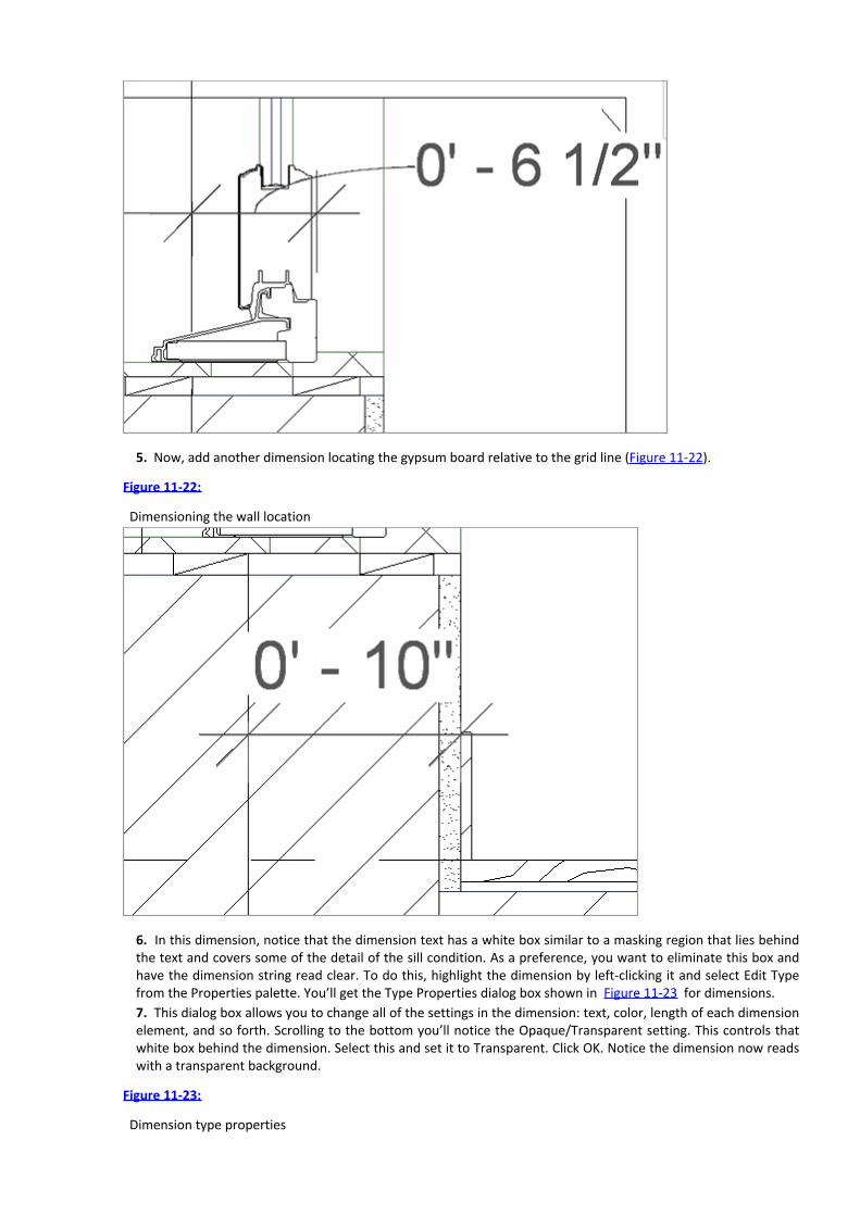
5. Now, add another dimension locating the gypsum board relative to the grid line (Figure 11-22).
Figure 11-22:
Dimensioning the wall location
6. In this dimension, notice that the dimension text has a white box similar to a masking region that lies behindthe text and covers some of the detail of the sill condition. As a preference, you want to eliminate this box andhave the dimension string read clear. To do this, highlight the dimension by left-clicking it and select Edit Typefrom the Properties palette. You’ll get the Type Properties dialog box shown in Figure 11-23 for dimensions.7. This dialog box allows you to change all of the settings in the dimension: text, color, length of each dimensionelement, and so forth. Scrolling to the bottom you’ll notice the Opaque/Transparent setting. This controls thatwhite box behind the dimension. Select this and set it to Transparent. Click OK. Notice the dimension now readswith a transparent background.
Figure 11-23:
Dimension type properties

8. Let’s add one final dimension string. Add a dimension locating the window sill relative to the floor, as shownin Figure 11-24.
Figure 11-24:
Dimensioning the window sill
9. Notice that this dimension is an awkward number and probably not something we want to include in the CDset. Remember that in Revit, dimensions simply report the relative location of objects—they cannot be forcedwith values. So to change the dimension string, you’ll need to change the location of one of the two objectsyou’ve dimensioned. Since the floor is probably not going to move, you can reposition the window slightly. Byselecting the window, notice that the dimension string turns blue and the numbers get very small (Figure 11-25).
Figure 11-25:
To change the dimension string value, change the location of the objects dimensioned by selecting the window.

10. Here you can key in a more reasonable value. Select the blue text and type 1 4 [400 mm] in the text box(Figure 11-26). Press Enter and the window will push up just a bit and reset the dimension string.11. With all the dimensions on the detail, it should look like Figure 11-27.
Figure 11-26: Keying a value into a dimension string
Figure 11-27: The dimensioned detail
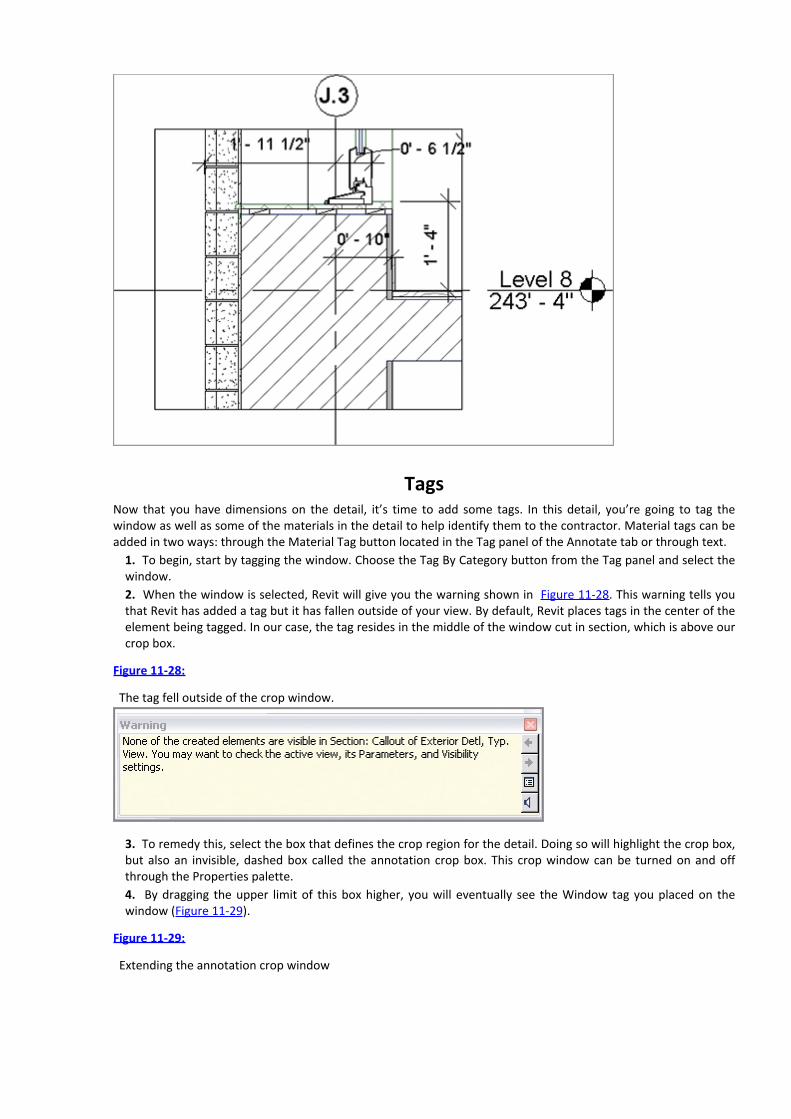
TagsNow that you have dimensions on the detail, it’s time to add some tags. In this detail, you’re going to tag thewindow as well as some of the materials in the detail to help identify them to the contractor. Material tags can beadded in two ways: through the Material Tag button located in the Tag panel of the Annotate tab or through text.
1. To begin, start by tagging the window. Choose the Tag By Category button from the Tag panel and select thewindow.2. When the window is selected, Revit will give you the warning shown in Figure 11-28. This warning tells youthat Revit has added a tag but it has fallen outside of your view. By default, Revit places tags in the center of theelement being tagged. In our case, the tag resides in the middle of the window cut in section, which is above ourcrop box.
Figure 11-28:
The tag fell outside of the crop window.
3. To remedy this, select the box that defines the crop region for the detail. Doing so will highlight the crop box,but also an invisible, dashed box called the annotation crop box. This crop window can be turned on and offthrough the Properties palette.4. By dragging the upper limit of this box higher, you will eventually see the Window tag you placed on thewindow (Figure 11-29).
Figure 11-29:
Extending the annotation crop window

5. Notice that the tag has a leader line associated with it. You’ll want to move the tag, but also remove theleader line. To do so, highlight the tag, and in the Options Bar, deselect the Leader check box (Figure 11-30).Doing so will allow you to drag the tag down—leader free—and place it within the crop region.
Figure 11-30:
Removing the leader from the Window tag
6. With the Window tag in place, now let’s add a Material tag. Choose the Material Tag button from the Tagpanel. You’ll be prompted to load the family, so navigate to Annotations ⇒ Architectural again and chooseMaterial Tag.rfa. Material tags allow you to tag materials consistently through out the model. This means if youtag something like Concrete once in the model, the material will remember the tag you used and will show thatsame tag every time you tag it in any other view. Once the tag is selected, mouse over the vertical panel shownin Figure 11-31. The material there has been prepopulated with 5/8ʺ GYPSUM BD as a tag. Select the materialand place the tag.
Figure 11-31:
Using the Material tag

7. With the tag placed, you’ll notice that by default there is no arrowhead. Select the tag and choose Edit Typefrom the Properties palette. Here you can give the tag an arrowhead. Choose 30 Degree Arrow and click OK(Figure 11-32).
Figure 11-32: Adding an arrowhead to the tag
In the same way, you can populate the remainder of the materials in the detail. For materials that aren’t alreadyspecified, Revit will provide you with a question mark. Simply click on the question mark and you can enter the textdescribing that material. Once entered, all other materials of that type within the model will automatically showwhat you just typed. Changes made to this material will also be broadcast through the model.
TextNot all elements in Revit have materiality to them and there are times when tags are not the best way to conveyinformation. For the rest of the information you want to communicate, use Text. The Text tool is located on theText palette of the Annotate tab. When you’re using text in your model, it’s important to remember that text is notlinked to any element or material. Labeling something with text or using text to call out notes doesn’t dynamicallyupdate as elements change within the model.
1. In our example detail, the shims you placed as part of the window family do not have a way to tag a materialand need to be called out using text. Choose the Text command from the Annotate tab. Doing so opens theModify | Text tab and you’ll see the tools on the Format panel. These tools control the leaders, leader location,justification, and font formats, respectively.For now, leave the selections at the defaults, choose a location on the screen, and click the left mouse button.This begins a text box. Type 1/2ʺSHIMS (Figure 11-33).
Figure 11-33:

Adding text to the detail
2. Once you’ve added text to the box, you’ll notice that the Modify menu has changed. You now have the optionto add and remove leaders. To add a leader, click the Add Leader button at the upper left of the Format panel
.With the leader added, you can move the text and leader into position with the other notes. In this way, you
can complete the annotations on the detail (Figure 11-34) and begin the next one.
Figure 11-34: Finishing the detail
Legends
Legends are unique views in Revit as they are the only view type you can place on more than one sheet. These canbecome great tools for things like general notes, key plans, or any other view type that you will want to haveconsistent across several sheets. It’s also important to note that anything you place inside a legend view—doors,walls, windows, and so on—will not appear or be counted in any schedules. Legend elements live outside of anyquantities present in the model.
The Legend tool is located on the View tab. There are two types of legends you can create from this menu: a
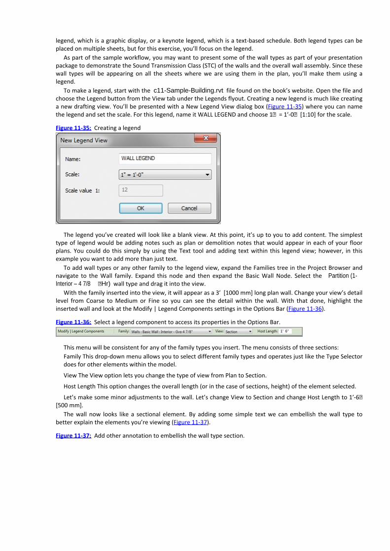
legend, which is a graphic display, or a keynote legend, which is a text-based schedule. Both legend types can beplaced on multiple sheets, but for this exercise, you’ll focus on the legend.
As part of the sample workflow, you may want to present some of the wall types as part of your presentationpackage to demonstrate the Sound Transmission Class (STC) of the walls and the overall wall assembly. Since thesewall types will be appearing on all the sheets where we are using them in the plan, you’ll make them using alegend.
To make a legend, start with the c11-Sample-Building.rvt file found on the book’s website. Open the file andchoose the Legend button from the View tab under the Legends flyout. Creating a new legend is much like creatinga new drafting view. You’ll be presented with a New Legend View dialog box (Figure 11-35) where you can namethe legend and set the scale. For this legend, name it WALL LEGEND and choose 1ʺ = 1ʹ-0ʺ [1:10] for the scale.
Figure 11-35: Creating a legend
The legend you’ve created will look like a blank view. At this point, it’s up to you to add content. The simplesttype of legend would be adding notes such as plan or demolition notes that would appear in each of your floorplans. You could do this simply by using the Text tool and adding text within this legend view; however, in thisexample you want to add more than just text.
To add wall types or any other family to the legend view, expand the Families tree in the Project Browser andnavigate to the Wall family. Expand this node and then expand the Basic Wall Node. Select the Partition (1-Interior – 4 7/8 ʺHr) wall type and drag it into the view.
With the family inserted into the view, it will appear as a 3ʹ [1000 mm] long plan wall. Change your view’s detaillevel from Coarse to Medium or Fine so you can see the detail within the wall. With that done, highlight theinserted wall and look at the Modify | Legend Components settings in the Options Bar (Figure 11-36).
Figure 11-36: Select a legend component to access its properties in the Options Bar.
This menu will be consistent for any of the family types you insert. The menu consists of three sections:Family This drop-down menu allows you to select different family types and operates just like the Type Selectordoes for other elements within the model.
View The View option lets you change the type of view from Plan to Section.
Host Length This option changes the overall length (or in the case of sections, height) of the element selected.
Let’s make some minor adjustments to the wall. Let’s change View to Section and change Host Length to 1ʹ-6ʺ[500 mm].
The wall now looks like a sectional element. By adding some simple text we can embellish the wall type tobetter explain the elements you’re viewing (Figure 11-37).
Figure 11-37: Add other annotation to embellish the wall type section.


Chapter 12
Creating Drawing Sets
While the industry continues to move toward a 3D BIM model as a construction deliverable, today we still need toproduce 2D documents for a construction set. Fortunately because of Revit, we can create these sets with moreaccuracy and dependability than in the past. In this chapter, you will work on taking the elements and creatingdocumentation.
In this chapter, we’re going to introduce a scenario that will mimic what might happen on a real project inpreliminary design. You’ll be using the Residence.rvt model from the book’s web page(www.sybex.com/go/revit2012essentials) in the Chapter 12 folder.
Here’s the story: You have recently completed some design work in advance of your upcoming pricing packagefor a residential design project. You will need to lay the plans, elevations, and perspectives out on some sheets forthe package. But you want to help the contractor with some quantities, so you also want to include someschedules. With this scenario in mind, you need to lay out the views already created onto sheets, create someschedules, and then get the drawing set printed.
In this chapter, you learn the following skills:Creating schedules
Placing views on sheets
Printing documents
Creating SchedulesSchedules are lists and quantities of elements and element properties within the model. They itemize objects,including building families such as walls, doors, and windows; calculate quantities, areas, and volumes; andquantify elements such as the number of sheets, keynotes, and so on. They are another way to view a Revit model.Once created, they are dynamically kept up-to-date with any changes that occur to the model itself.
Understanding Schedules
In a project workflow, creating schedules of objects, areas, or quantities is usually one of the most laborious tasksfor architects. When this process is performed manually, it can take a very long time and typically results in errorsrequiring much checking and rechecking of the information. In Revit, all the elements have information about theirproperties defined within the model. You also have the option to add information or categories to any existingelement. For example, in Revit, doors have properties such as size, material, fire rating, and cost. All of thisinformation can be scheduled and quantified. As those doors are changed within Revit, the properties update inthe schedule.
Revit lets you schedule elements based on the element’s properties. This means that almost anything placed ina Revit model can be scheduled and quantified. Because the schedule is simply viewing the elements within themodel in a nongraphical way, making change to the elements in a schedule view makes changes to the element inthe model, and vice versa.

Revit has several types of schedules. They can all be accessed from the Create panel of the View tab. TheSchedule flyout is shown in the margin. There are five primary types of schedules you can create using Revit. Let’slook at each:
Schedule/Quantity This is the most commonly used schedule type in Revit. This schedule allows you to list andquantify all the element category types in Revit. You would use this type to make door schedules, wallschedules, window schedules, and so on. These schedule types are limited to scheduling properties within thesame category.
Material Takeoff This type of schedule lists all the materials and subcomponents of any Revit family category.You can use a material takeoff to schedule any material that is placed in a component or assembly. Forexample, you might want to know the cubic yardage of concrete within the model. Regardless of whether theconcrete is in a wall or floor or column, you can tell the schedule to report the total amount of that material inthe project. Material takeoffs will report material properties across multiple categories.
Sheet List This schedule allows you to create a list of all the sheets in the project.
Note Block This schedule lists the notes that are applied to elements and assemblies in your project. You canalso use a note block to list the annotation symbols (centerlines, north arrows) used in a project.
View List This schedule shows a list of all the views in the Project Browser and their properties.
Each of these schedule types has a host of categories that you can mix and match to make schedules and trackelements within the model. All of these schedules are broken down into some common elements that allow you tobuild and customize your schedules. Let’s step through these elements and see how they can be used.
To begin a schedule, select Schedule/Quantity since it is the most widely used of schedule types. Selecting anyof these schedule types will give you the New Schedule dialog box (Figure 12-1).
Figure 12-1: Creating a new schedule

This dialog box allows you to choose the category you would like to schedule. As you move through the list onthe left, you can see a host of different schedule categories, as listed here:
Areas (Gross and Rentable) Casework Ceilings
Curtain Panels Curtain Systems Curtain Wall Mullions
Doors Electrical Equipment Electrical Fixtures
Fascias Floors Furniture
Furniture Systems Gutters Lighting Fixtures
Mass Mass Floors Mechanical Equip.
Parking Planting Plumbing Fixtures
Property Line Seg. Property Lines Railings
Ramps Roofs Rooms
Site Slab Edges Specialty Equipment
Stairs Structural Columns Structural Foundations
Structural Framing Topography Wall Sweeps
WallsWind

ows
If there aren’t enough categories for you to choose from to create customized schedules, Revit provides avenue to add additional options. At the bottom-left corner of the New Schedule dialog box is the Show CategoriesFrom All Disciplines check box. Selecting this check box gives you the ability to schedule elements from MEP andStructural categories. This option can be useful when you have those disciplines supplying Revit files to you andyou are linking them into your architectural model.
Revit also gives you the opportunity to create schedules that span categories. The first option in the dialog boxin Figure 12-1 is the Multi-Category schedule. You might want to schedule all the casework and furnishings in aproject simultaneously. Or perhaps you want to schedule all the windows and doors if they are being ordered fromthe same manufacturer. A Multi-Category schedule allows you to combine a number of categories into oneschedule. One of the limits of this schedule type is that you cannot schedule host elements (walls, floors, ceilings,and so on) but only their materials and family components.
With this description in mind, let’s look at the other options when creating a schedule. Choose Walls and clickOK. Doing so opens a new dialog box called Schedule Properties. Here, you can set the various properties of aschedule that define not only how it looks, but what information it reports.
There are five tabs across the top: Fields, Filter, Sorting/Grouping, Formatting, and Appearance. Each of thesecontrols different aspects of the schedule. Let’s step through each of these tabs and see how they affect the lookand reporting of the schedule:
Fields The Fields tab (Figure 12-2) lets you select the data that will appear in your schedule. For the wallschedule, it shows all the properties available in the wall family (we chose Family And Type, Type Mark, andVolume). The list of available fields on the left will vary based on the family you chose to schedule. If you’veadded any project-based parameters to those family categories, they will be available here as well. Also noticeat the lower-left corner is the option Include Elements In Linked Files. Enabling this option allows you toschedule across multiple files and can be a great tool on larger projects.
Figure 12-2: The Fields tab
Filter On the Filter tab (Figure 12-3), you can filter out the data you don’t wish to show in your schedule. Filterswork like common database functions. For example, you can filter out all the sheets in a set that don’t beginwith the letter A. Or you can filter a material list so that it shows only items containing Concrete.
Figure 12-3: The Filter tab

Sorting/Grouping The Sorting/Grouping tab (Figure 12-4) lets you control the order in which information isdisplayed and which elements control that order. For instance, if you are creating a sheet index you can chooseto sort by Sheet Number or Sheet Name, depending on how you’d like the information displayed. You can alsodecide whether you want to show every instance of an item or only the categories for a family by using theItemize Every Instance check box at the bottom.
Figure 12-4: The Sorting/Grouping tab
Formatting The Formatting tab (Figure 12-5) controls the display heading for each field and whether the field isvisible on the schedule. It also controls other elements of the field, such as justification, display name, and

orientation of the header. This tab also allows you to use the Calculate Totals check box. Not all Revit fields willcalculate their total values at the bottom of the schedule. By highlighting the field on the left, you can check theCalculate Totals box and show a sum at the bottom for any numerical column.
Figure 12-5: The Formatting tab
Appearance The Appearance tab (Figure 12-6) controls the graphical aspects of the schedule, such as font sizeand style of text for each of the columns and headers in the schedule. It also allows you to turn the schedulegrid lines on and off, as well as modify the line thickness for the grid and boundary lines.
Figure 12-6: The Appearance tab
Once you’ve established the fields and look of your schedule, clicking OK gives you a preliminary layout. Thislayout can be modified at any time during the project, but it gives you a basis from which to begin. To modify the

schedule at any time, simply click the Element Properties button or right-click and choose Element Properties fromthe context menu.
Schedules have their own special tab on the ribbon that is active when you are viewing the schedule outside ofa sheet. The tab (Figure 12-7) allows you to select the properties, add and delete rows, and show or hide columnswithin the schedule.
Figure 12-7: The Schedule tab buttons
Another key feature of this menu bar is Highlight In Model. This button allows you to select any element in theschedule from any cell and locate that element in the model. Let’s say you want to locate a particular door fromyour door schedule. Highlight the door in the schedule and click the Highlight In Model button, and Revit will takeyou to a different view with that door highlighted. This feature can be a useful way to locate elements in themodel, especially for larger models.
Now that you have an idea of the elements that compose a schedule, let’s return to our demonstrationworkflow and create a Rentable Area schedule based on the areas we’ve defined earlier in this chapter.
Making Schedules
Now that we’ve discussed some of the features of the Schedule tool, let’s open the Residence.rvt model andmake a couple of schedules. When you first open the model, you’ll notice that there are several views and sheetsalready created. This model is a work in progress—it’s a private residence of 1,230 square feet. The project is arenovation of a 1890s two-story brick. In the design, all the interior walls have been eliminated and put on a“demo” phase, which keeps the 19ʹ clear span as open as possible. All new interior walls have been added and theentire interior refreshed within the historic shell. Since the renovation is so substantial, the designer chose toreplace all the existing original windows with new insulated, wood windows. To assist the window manufacturerwith the custom sizes, you need to create a window schedule. To begin, choose the Schedule/Quantity buttonfrom the Schedule drop-down menu on the View tab.
The New Schedule dialog box (shown earlier in Figure 12-1) opens. Here you’ll make a series of selections tocreate the schedule. Follow these steps:
1. From the Categories list, select Window at the bottom. Since this project has multiple phases, you want tomake sure the phase is set to New Construction—you don’t need to schedule the windows you’re removing.Click OK when you’ve finished.2. We’re now going to step through the five tabs in the Schedule Properties dialog box. This will help you formatthe schedule and choose what you’d like to see. Starting with the Fields tab, choose the following fields:
Type This represents the family type or, in our case, the window name.Type Mark This is the letter that you’ll use on the elevations to define the window type in your document.Width Specify the window width.

Height Specify the window height.Count Specify the number of times a window type appears in the model.
Choose these fields from the Fields list on the left and, using the Add button, move them to the right (Figure 12-8). You can use the Move Up or Move Down button to change the order of the fields.
Figure 12-8:
Adding fields to our Window schedule
3. Choose the Sorting/Grouping tab. From the Sort By drop-down, choose Type.4. In our schedule, you want to make the window count read as it would in a spreadsheet: right-justified.Choose the Formatting tab and select Count from the list on the left. Change the Alignment setting to Right(Figure 12-9). In the same way, you can choose the Type Mark field and choose to center-justify it so all theletters will align nicely.
Figure 12-9:
Formatting the schedule

5. We’re going to leave the rest of the schedule at the defaults, so click OK. Revit will follow the directions youhave given it to display the schedule that appears in Figure 12-10. Note that you can also change any of theheading names by simply typing inside the box. Since Type Mark isn’t a value that most people relate to, we’vesimplified it to Type and made the rest of the field names all uppercase.
Figure 12-10: The Window schedule
Following these simple guidelines, you can create all kinds of schedules in your project.
Creating a Room ScheduleCreating other schedule types is fairly simple if you follow the guidelines we just went over and step through thetabs in the Schedule Properties dialog box. Since you have one schedule under your belt, let’s try anotherone—this time, you’ll create a room schedule. To do this, begin by choosing the Schedule/Quantity button fromthe Schedule drop-down on the View tab, and then follow these steps:
1. Choose Rooms from the New Schedule dialog box and click OK.2. Choose the following fields from the Schedule Properties dialog box:
Number
Name
Floor Finish

North Wall
East Wall
South Wall
West Wall
Area
Comments
When you’re done, click OK.3. On the Sorting tab, choose Number.4. On the Formatting tab, choose Area and justify to the right. Click OK to get the schedule you see in Figure 12-11.
Figure 12-11: Our Room schedule
Now, let’s do something slightly different with this schedule. Since four of our columns are dealing with wallfinishes, let’s add a header to those columns so you can group them under one header, Wall Finishes. To do so,start by selecting the four headers as shown in Figure 12-12. Grab one with your mouse and holding down the leftmouse button, drag across to select all four.
Figure 12-12: Selecting the wall finishes
With the four columns selected, choose the Group button from the Headers panel. This will give you a new rowabove your existing headers. Now you can type Wall Finishes to complete your schedule (Figure 12-13).
Figure 12-13: The Room schedule

Once this schedule is complete, you’ll notice that some of the fields already have data in them. This is due tothe fact that some of this information is generated automatically by Revit (like room areas) and some of it wasadded earlier in this process by adding room numbers to the plans or room names. Remember, schedules are justa nongraphical way of viewing the model—changes to the schedule will alter what you see in the model.
Creating a Sheet List
Sheet List is a different schedule type that you can create in Revit. The Sheet List schedule allows you to create alist of sheets in your project that are found within the Project Browser. This can be handy, especially on largerprojects where the sheet list can tend to get long. This tool is also located in the Schedules flyout on the View tab.
This schedule has a feature that allows you to create placeholders for sheets that are not yet created or will notbe a part of your discipline’s drawings. You can use this feature to create full sheet schedules including allconsultant drawings. It also allows you to create placeholder entries in the sheet schedule before you’ve createdthe sheets.
In our sample workflow, you have created several drawings and sheets, and you want to schedule them so youcan add a sheet list to your drawings. To do so, begin by selecting the Sheet List tool from the Schedules flyout.
1. You’ll see the now familiar Revit schedule dialog box starting with the Fields tab. From this tab, you need toselect two fields from the categories on the left and move them to the column on the right. Select the SheetNumber and Sheet Name categories (Figure 12-14).
Figure 12-14:
Creating the sheet list

2. On the Sorting/Grouping tab, choose to sort by Sheet Number and make sure the Itemize Every Instancecheck box is checked (Figure 12-15).
Figure 12-15:
Sorting by Sheet Number
3. Now, choose the Filter tab. You’ll be creating a sheet index for your presentation sheets, so you don’t want toinclude all the sheets in the set. You already have some of the construction documentation sheets in the file (theA series sheets), and you don’t want those reported in your schedule. You want to filter out all the sheets thatdon’t begin with the letter K (for the Kitchen sheets in this set).4. On the Filter tab, choose to filter by Sheet Number.5. From the next drop-down, choose Begins With.

6. In the third field, enter the letter A. The filter should look like Figure 12-16.7. Be sure to use an uppercase A, as the Boolean queries in Revit are case sensitive. When you’re done, click OK.What you should have is a schedule with nothing in it but sheet numbers that begin with the letter A. Now youneed to populate the rest of the sheet list.
8. To begin adding sheets to the sheet list, select the New Sheet button from the Create panel. This will give youa row with a blank for both of your headings, Sheet Number and Sheet Name.9. To your sheet list, you’ll add one of the two sheets you need for this set. You need a Plan sheet – A100.Clicking the New Sheet button will give you the New Sheet dialog box so you can add a sheet to the set (Figure12-17).
Figure 12-16:
Filtering out sheets
Figure 12-17:
Adding sheets to the list

10. Choose the 22×34 Sheet CD – C1 sheet and click OK. This will add a sheet to your project browser. Bydefault, the sheets are added in sequential order, so whichever sheet was added the most recently will be thenext sheet in the list. In this example, it will appear as A051, right after the A050 sheet. Right-click the sheet andchoose Rename from the context menu. Rename the sheet to A100 – Floor Plans. You’ll see a blank sheet inyour view window. Closing this view will take you back to the schedule view with your new sheet in the list(Figure 12-18).
Figure 12-18: Adding sheets to the set
Placing Views on SheetsThroughout this book, you have created several different kinds of views, from plans to elevations to perspectives.Eventually, you will need to lay out those views onto sheets so they can be printed or converted to PDF format andsent to clients or team members for review.
Creating sheets in Revit is very easy. As you’ve already seen, they can be created through a Sheet List schedule.You can also create sheets by right-clicking the Sheet node in the Project Browser and selecting New Sheet fromthe context menu. Regardless of which method you use to create them, let’s walk through laying these views out

on sheets and see how each view can be further manipulated once it’s placed on a sheet.
Adding Floor Plans to the Sheet
Since you have already created a series of views, let’s use the sheet you’ve just made for this purpose. Open theA100 – Floor Plans sheet in the view window by double-clicking it in the Project Browser. Now, let’s add our firstview: the Basement floor plan. To begin, drag and drop the plan from the Project Browser and onto the sheet. Theview will show at the proper scale and with a View Title already established. You can then drag the view across thesheet to place it where you’d like to have it (place it on the left side—you’ll add more). Figure 12-19 shows theview placed on the sheet.
Now, since we have a bit more space left on the sheet, let’s add a couple of other views. Add Level 1 and Level 2by dragging and dropping them from the Project Browser and on to the sheet. You should notice when you’replacing your second and third views on the sheet that you will be presented with an outline of the plan view with adashed line in the center of the view. This is an alignment tool; Revit is assuming that you want the plans to alignon the sheet and it is intelligent enough to aid you in this process. You can casually drag the views around on thesheets enough to find the alignment lines and to ensure that all your plans will line up (Figure 12-20). Your sheetfull of views should look like Figure 12-21.
Figure 12-19: Placing the view on a sheet
Figure 12-20: Aligning views on sheets

Figure 12-21: All the views placed on the sheet
Once the views are placed on a sheet, there will inevitably be a bit of cleanup you’ll want to do to the drawingsto get everything placed properly and looking good. First of all, by default, Revit will place the View tag in roughlythe same place for each view, and that might not be the location you ultimately want it to be in. Revit will alsonumber the views sequentially (1, 2, 3,…) in order of placement.

Let’s adjust the view tags a bit on the sheets. To adjust the text in the tags, start by selecting the viewitself—not the tag. To adjust the tag location, you’ll want to select the tag itself.
1. Start by selecting the view for the Basement. The tag will highlight in blue. You want to change two things onthe tag: the number and the length of the line.2. Select the number 1 and change it to A1 to reference the ConDoc drawing system—letters vertically along theside of the sheet and numbers across the bottom of the sheet. Move the detail to the location on the lower-leftcorner of the detail on the drawing sheet.3. Next, using the blue grips on the view tag line, drag the right grip closer to the end of the Basement text. Yourtag will look like Figure 12-22.
Figure 12-22:
The edited view tag
4. Now, clearly you can’t leave the view tag there as it’s falling off the left edge of the sheet—you need to moveit to a better position. Click off the tag, anywhere in the view, to deselect the tag. You can also press the Esc keytwice or select the Modify arrow at the upper left. Then, select the tag itself. It will highlight blue again, butwithout the grips on the line. Now, you can click and drag the tag to any location on the sheet (Figure 12-23).
Figure 12-23:
Moving the view tag
5. Do the same to the other two views. Rename Level 1 to A6 and Level 2 to A11 to match their location onthe sheet as shown, shortening the view tag lines to a more appropriate length (Figure 12-24).
Figure 12-24: Laying out the rest of the sheet views

To finish organizing your sheet, you want to add a few lines to divide the different views. You can do so easily by
using the Detail Line tool , which can be found on the Annotate tab.1. Choose Detail Line from the Detail Panel.2. Doing so activates the Modify | Place Detail Lines context menu. From the Line Style panel on the far right,choose Wide Lines from the drop-down.
3. Once the desired line style is selected, you’re ready to start drawing lines. By default, the straight line tool isactive, and you can select one of the nodes on the sheet between views and draw a vertical line between theBasement and Level 1 and between Level 1 and Level 2 (Figure 12-25).
Figure 12-25: Adding lines to the sheet

With these dividing lines in place, you notice that one of your annotations in the Basement view is a little tooclose to the drafting line (Figure 12-26). You want to adjust it.
To do this, you could simply open the view and adjust the text box, but you wouldn’t have the sheet as areference. Instead, you’re going to use a command called Activate View.
Figure 12-26: Adjusting text in the sheet view
Activating a view is like working in model space through paperspace in CAD. You’re working on the actual view
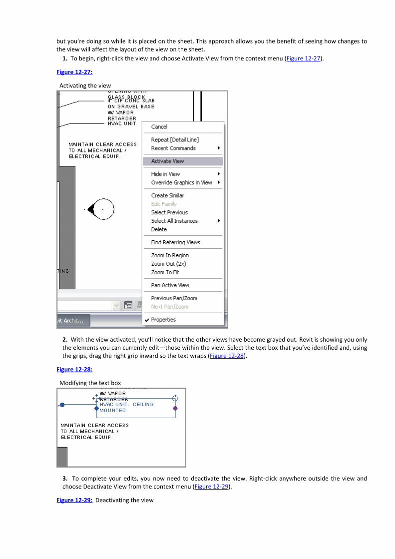
but you’re doing so while it is placed on the sheet. This approach allows you the benefit of seeing how changes tothe view will affect the layout of the view on the sheet.
1. To begin, right-click the view and choose Activate View from the context menu (Figure 12-27).
Figure 12-27:
Activating the view
2. With the view activated, you’ll notice that the other views have become grayed out. Revit is showing you onlythe elements you can currently edit—those within the view. Select the text box that you’ve identified and, usingthe grips, drag the right grip inward so the text wraps (Figure 12-28).
Figure 12-28:
Modifying the text box
3. To complete your edits, you now need to deactivate the view. Right-click anywhere outside the view andchoose Deactivate View from the context menu (Figure 12-29).
Figure 12-29: Deactivating the view

Adding the SchedulesWith your A100 sheet laid out and ready to print, you can quickly finish your sheet set by adding the Windowschedule you created earlier. Adding a schedule is just like adding any other view—you simply drag and drop itfrom the Project Browser onto the sheet.
1. Open sheet G000 Cover Sheet by double-clicking it in the Project Browser (Figure 12-30).2. Grab the Window schedule from the Project Browser and drag and drop it into the open area on the sheet.
Figure 12-30: G000 Cover Sheet
With the schedule on the sheet, it looks like it needs a bit of adjustment. You can redefine the column spacingso you can make any visual adjustments to the schedule while it is on the sheet to help it read better. Suchadjustments do not change the actual schedule but just its appearance on the sheet itself.
To do so, highlight the schedule by selecting it. The schedule will turn blue and you’ll have a few new grips tohelp you make changes (Figure 12-31). The blue inverted triangles at the top of each column allow you to modifythe column widths. Grab one and drag it left or right to change the column sizing.
Figure 12-31: Modifying the schedule on the sheet

You’ll also notice a blue cut symbol . This cut symbol allows you to break the schedule into partswhile on the same sheet. This can be especially handy if you have a long schedule like a room or door schedule andit has too many rows to fit on your sheet vertically. Selecting this tool breaks the schedule in half (and you canbreak it into half again and again) so that you can take advantage of the horizontal real estate on your sheet. If youchoose to separate your schedule in this fashion, it still retains all the necessary information and all the portionscontinue to automatically fill themselves out dynamically as a single schedule would. You also have theopportunity to change the overall height of the schedule once it is broken up by grabbing the grips at the bottomof the schedule and dragging up and down.
With your schedule on the sheet and the columns properly formatted, you can drag the schedule around on thesheet until it’s located where you’d like to have it. To move it around, click and hold the left mouse button downon the schedule. As you move it around on the sheet, you’ll notice that like other views in Revit, the schedule willjustify with the other schedules on the sheet and give you a light green dashed line to help align the two. Yourfinished sheet will look like Figure 12-32.
Figure 12-32: The finished sheet G000
Printing DocumentsWith all of your documents and sheets laid out, you will eventually need to get the sheets out of Revit and into a

printed format. If you’ve been working in the Windows environment, you’ll find that printing from Revit isstraightforward, because it’s similar to other Windows-based applications.
The Print Dialog BoxTo print, you do not need to be in any particular view or sheet. Select the Application menu and choose Print ⇒Print to open the dialog box shown in Figure 12-33. All the features for printing are found here. Let’s step throughthis dialog box and explore each element.
Figure 12-33: Print dialog box
The drop-down menu at the top of this dialog box allows you to select the printer or plotter you wish to printto. This can be a physical printer or a virtual one (like Adobe Acrobat Distiller). You add printers to this list usingyour Windows Printer control panel. Most of the controls you need to use can be found at the bottom of thisdialog box in the Settings section on the right and the Print Range on the left.
Print SettingsThe printing environment is set up using the Print Setup dialog box (Figure 12-34). Here you set up a printer andsettings for printing. You can save these settings with a name so that you can reuse them in later Revit sessions.These settings can also be transferred to other Revit projects if need be, using the Transfer Project Standards toollocated on the Manage tab. Let’s take a look at some of the printing options available to you.
Hidden Lines ViewsViews in Revit can be displayed in four graphic modes: Wireframe, Hidden Line, Shaded, and Shaded With Edges.The most commonly used type is Hidden Line. You’ll choose this type for floor plans, sections, and elevations, andsometimes even for 3D.
Revit lets you select whether you wish to print this type of view with vector processing or raster processing ofthe hidden lines. Vector is faster; however, you need to be aware of some nuances when working with hidden lineviews. For example, transparent materials (like glass) print transparent with raster processing but opaque withvector processing.
Figure 12-34: The Print Setup dialog box

OptionsThe Options pane is at the lower left in the Print Setup dialog box. The pane includes these options:
View Links In Blue View links are hyperlinked tags that lead you from one view to another or from a sheet to aview. They appear blue in Revit and print black by default, but you can specify to print them in blue, which ishow they appear on the screen.
Hide Ref/Work Planes; Hide Scope Boxes; Hide Crop Boundaries These three check boxes let you decidewhether to print various Revit-specific graphics, including reference planes, scope boxes, and crop boundaries.
Hide Unreferenced View Tags During the course of a project, you may create a lot of elevation tags, sectionflags, or detail callouts for working purposes that you don’t wish to be printed in the final documents or placedon any sheet. These view tags are referred to as unreferenced, and Revit gives you the option to not print them.
Once all of your options are set, you have the ability to save the settings so you can quickly reuse them onfuture prints. Choose the Save As button on the right, name the setting 11×17, and click OK. Now, click OK to closethis dialog box. This will take you back to the Print dialog box.
Print RangeThe other important part of the Print dialog box is the Print Range. In this section, you can define exactly whatareas, sheets, or views you want to print. It includes these options:
Current Window This option prints the full extent of the open view, regardless of what extents of that view arevisible currently on your screen.
Visible Portion Of Current Window This option prints only what you see in the frame of the open windowframed for the sheet size you’ve selected.
Selected Views/Sheets This option allows you to define a reusable list of views, sheets, or any combinations ofviews and sheets. This way, you can essentially batch-print a job by sending large quantities of sheets to theprinter in one shot and save these selections for later print jobs.
This dialog box lets you pick any view or sheet to include in the View/Sheet Set. If you only want to includesheets in a set, use the Show options at the bottom of the dialog box to shorten the visible list. Doing so allows

you to select only sheets or only views if you so choose.
This is a great tool to help define print lists. Some examples of what you might want to use these selections forwould be a 100 percent construction document package or a specific set of presentation sheets.
1. In our example, you want to print a set of sheets. Deselect the View check box at the bottom of this dialogbox and Revit will display a list of the sheets you’ve created to date.2. Next, check the A series sheets, the D100 sheet, and the G000 sheet you just added the schedule to (Figure12-35).3. Since you will more than likely want to print this set again, choose Save As from the menu on the right andname the set Set 1. This will keep your current collection of sheets together, and if you want to reprint this set,grab the set name from the drop-down menu. Remember, if you add more drawings to the set, by default theywon’t be added to this print set. You’ll need to revisit this dialog box, add the sheets, and click the Save button.For now, click OK to close this dialog box.
Figure 12-35:
Checking the desired sheets
4. Our final dialog box looks like Figure 12-36. Clicking OK here will print the six selected drawings to the printerlisted at the top. Clicking Close saves your print setup and closes the dialog box.
Figure 12-36: Finishing the prints
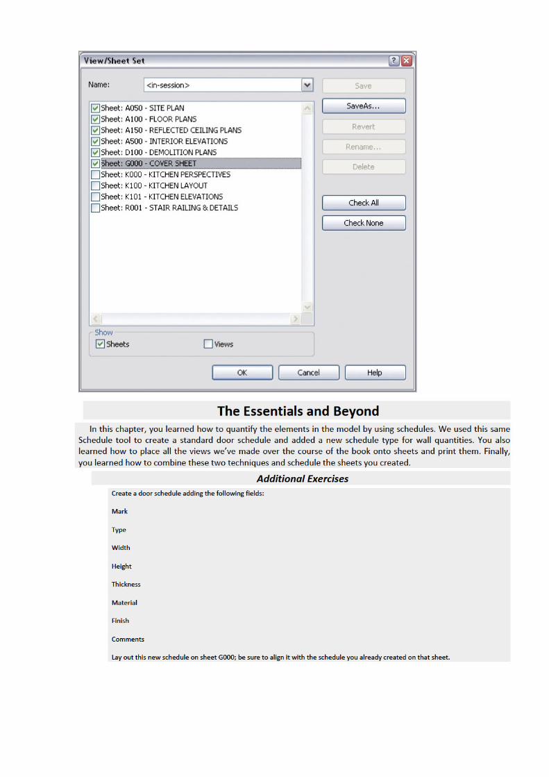

Chapter 13
Workflow and Other Revit Essentials
Understanding Revit and how to use the software is not a difficult challenge. The real challenge is determining howusing Revit and BIM changes your organization’s culture and your project’s workflow—especially if you’re comingfrom a CAD-based environment. Revit can be more than just a different way to draw a line. In this chapter, we’llfocus on what those changes are and provide some tools on how to manage the transition.
In this chapter, you learn the following skills:Understanding a BIM workflow
Modeling site
Detailing in Revit
Performing quality control on your Revit model
Understanding a BIM WorkflowRegardless of the workflow you have established, moving to Revit is going to be a change. You’ll still need sometools to help transition from your current workflow to one using Revit. To begin, we’ll cover some of the coredifferences between a CAD-based system and a BIM-based one.
Moving to BIM is a shift in how designers and contractors look at the design and documentation processthroughout the entire life cycle of the project, from concept to occupancy. In a traditional CAD-based workflow,represented in Figure 13-1, each view is drawn separately with no inherent relationship between drawings. In thistype of production environment, the team creates plans, sections, elevations, schedules, and perspectives andmust coordinate any changes between files manually.
Figure 13-1: A CAD-based workflow

In a BIM-based workflow, the team creates a 3D, parametric model and uses this model to automaticallygenerate the drawings necessary for documentation. Plans, sections, elevations, schedules, and perspectives areall by-products of creating an embellished a BIM model, as shown in Figure 13-2. This enhanced documentationmethodology not only allows for a highly coordinated drawing set but also provides the basic model geometrynecessary for analysis such as daylighting studies, energy, material takeoffs, and so on.
Using Revit becomes more than a change in software; it becomes a change in workflow and methodology. Asvarious design specializations interact and create the building model (Figure 13-3), you can see how structure,mechanical, energy, daylight, and other factors inform design direction. You can also draw relationships betweensome of these elements that might not have been as obvious in a more traditionally based approach. Althoughsome of these specialties (such as structure and mechanical) are historically separate systems, by integrating theminto a single design model, you can see how they interact in relation to other systems with a building. Analysis suchas daylighting can inform your building orientation and structure. Depending on your glazing, it can also affect yourmechanical requirements (as solar gain). You can see some of these effects through a computational fluiddynamics (CFD) model (used to calculate airflow). Geographic information system (GIS) data will give you yourrelative location globally and allow you to see how much sunlight you will be receiving or what the localtemperature swings will be during the course of a day. As you can see, all of these variables can easily affectbuilding design.
Figure 13-2: A BIM workflow
As with any methodological change, you’ll have success if you address all the factors. Project success happenson more than a financial or chronological level. It is also determined by a team’s ability to replicate successfulresults. A difficult aspect of transitioning to BIM is predictability. Any system or method, even if it is inherentlyinefficient, is at some level successful if the system is predictable. If you can say that x effort + y time will yield zresult, there is an established comfort level with that system even if it is an inefficient system. When you move toBIM, the system automatically becomes unpredictable because team members need to experience the newsystem to establish a comfort level with the given results. No longer does x effort + y time yield z; instead, theresult is unknown.
Figure 13-3: The integrated design model
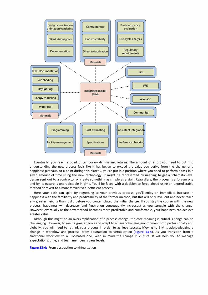
Eventually, you reach a point of temporary diminishing returns. The amount of effort you need to put intounderstanding the new process feels like it has begun to exceed the value you derive from the change, andhappiness plateaus. At a point during this plateau, you’re put in a position where you need to perform a task in agiven amount of time using the new technology. It might be represented by needing to get a schematic-leveldesign sent out to a contractor or create something as simple as a stair. Regardless, the process is a foreign oneand by its nature is unpredictable in time. You’ll be faced with a decision to forge ahead using an unpredictablemethod or revert to a more familiar yet inefficient process.
Here your path can split. By regressing to your previous process, you’ll enjoy an immediate increase inhappiness with the familiarity and predictability of the former method, but this will only level out and never reachany greater heights than it did before you contemplated the initial change. If you stay the course with the newprocess, happiness will decrease (and frustration consequently increases) as you struggle with the change.However, eventually as the new method becomes more predictable and comfortable, your happiness can achievegreater value.
Although this might be an oversimplification of a process change, the core meaning is critical. Change can bechallenging. However, to realize greater goals and adapt to an ever-changing environment both professionally andglobally, you will need to rethink your process in order to achieve success. Moving to BIM is acknowledging achange in workflow and process—from abstraction to virtualization (Figure 13-4). As you transition from atraditional workflow to a BIM-based one, keep in mind the change in culture. It will help you to manageexpectations, time, and team members’ stress levels.
Figure 13-4: From abstraction to virtualization

Staffing a BIM projectAs you rethink the process of design and documentation, one of the semantic changes you will need to address isstaffing. A common misconception of project management when teams are first moving from CAD to BIM is thatstaffing the project will be the same in both workflows. This couldn’t be further from the truth. When theworkflow changes, staffing allocations, time to complete tasks, and percentage of work by phase are all affected asa by-product of the change of method.
In a CAD-based project, the level of effort during each of the phases is fairly well known. The industry has beenusing some metrics over the past several years that should be fairly familiar. There is modest effort and staffing inconceptual design and schematic design phases, and this effort builds until it crescendos during constructiondocumentation. At this phase, a CAD project can greatly increase the number of staff in an effort to expedite thecompletion of the drawing set. This staff increase can be effective because the CAD drawings are typically separatefiles and moving lines in one drawing won’t dynamically change another.
In a BIM-based framework, there is still a gradual increase of staffing and effort through conceptual design andinto the schematic phase, but the effort during schematic design is greater using BIM than in CAD. Duringschematic design and design development, the project team is still performing all the same tasks that occur in anydesign process: testing design concepts, visualizations, or design iteration. The increase in effort during the earlydesign phases allows the team to use the parametric nature of the model to significantly reduce the effort laterduring construction documents, allowing for a decrease in the overall effort over the project cycle.
Project Roles Using RevitWith such a significant change in the effort behind a BIM-based project flow, it’s also important to understand howthis can change the various roles and responsibilities for the project team. The changes in traditional roles canbecome a barrier to many projects successfully adopting BIM. Project managers need to be able to predict staffingand time to complete tasks throughout the project phases and have relied on past precedent of staff and projecttypes to do this. Since a BIM-based project can significantly alter the project workflow, many of the historictimetables for task completion are no longer valid. However, a BIM-based project can be broken down into a fewprimary roles that will allow you some level of predictability through the various project phases. Although thespecific effort and staffing will vary between offices (and even projects), there are some general roles that willneed to be accounted for on every project.
There are three primary roles on every BIM project:Architect Deals with design issues, code compliances, clear widths, wall types, and so on
Modeler Creates content in 2D or in 3D

Drafter Deals with annotations, sheet layout, view creation, and detail creation
These roles represent efforts and general tasks that you need to take into account on any Revit project. On alarge project, these roles could also represent individual people, whereas on a smaller project they might be all thesame person or one person might carry multiple roles. We’ll now cover each of these in a bit more detail anddiscuss how these roles interact with the project cycle.
ArchitectThe role of the architect is to deal with the architectural issues revolving around the project. As the model is beingcreated, you will naturally have to solve issues like constructability and wall types, set corridor widths, deal withdepartment areas, and deal with other issues involving either codes or the overall architectural design. This rolewill be the one applying standards to the project (as in wall types, keynotes, and so on) and organizing thedocument set. This role will need to be present on the project from the beginning to ensure consistency of thevirtual building creation and isn’t necessarily limited to only one person. This role also might or might not be a“designer.” Although it is possible to do early design in Revit, many project teams prefer to utilize other tools suchas Google SketchUp or even pencil and trace paper. The job of the architect is steering the creation of the buildingwithin Revit. Tasks for this role include the following:
Leading the creation of architectural elements and building from within the model
Designing around code requirements and other building logistics
Constructability and detailing aspects of the design
ModelerThe role of the modeler is to create all the 2D and especially the 3D content needed in the project. This contentincludes all the parametric families for elements such as windows, doors, casework, wall types, stairs, railings, andfurnishings. Typically, this role is the responsibility of less experienced staff, who might not be able to fulfill therole of architect. These less experienced positions tend to have longer periods of undisturbed time, making thembetter suited to deal with some of the longer, more involved tasks in modeling content. Finally, they also tend tohave some 3D experience coming out of school. They might not have worked with Revit directly but possibly withAutodesk 3ds Max or Google SketchUp, and are thereby familiar with working in a 3D environment. Tasks for thisrole include:
DrafterThe role of the drafter is to create sheets and views and embellish those views with annotations or other 2Dcontent. This role will be doing the bulk of the work needed to document the project. In earlier stages of theproject, this role is typically assumed by either the architect or the modeler, but as documentation gets movinginto high gear, it can quickly become the role of multiple people on a larger project. Tasks for this role include thefollowing:
Keynoting
Dimensioning
Setting up sheets and views
Creating schedules
From a staffing planning purpose, we are discussing the ideal times to bring in some of these various roles intothe project. At the inception of a project design, a modeling role will be of the best use. This person can helpcreate building form, add conceptual content, and get the massing for the building established. If you’re using theconceptual modeling tools, the modeler can even do some early sustainable design calculations.
Once the project begins to take a more established form and you complete conceptual design, you’ll need anarchitect role to step into the project. As in a typical project, you’ll have to mold the form into a building byapplying materials, applying wall types, and validating spatial requirements and the owner’s program.
During schematic design, you’ll need to include the role of the drafter to begin laying out sheets and creatingviews. These sheets and views don’t have to be for a construction document set yet, but you’ll have to establishviews for any schematic design submittals. If these views are set up properly, they can be reused later for design

development and construction document submittals as the model continues to gain a greater level of detail.What you’d like to avoid for your project staffing, if possible, is adding staff during the construction document
phase. In a BIM/Revit workflow, this can sometimes cause more problems than it solves and slow down the teamrather than get work done faster.
Adding Team Members to Fight FiresIn many projects, there comes a time when the schedule gets tight and project management wants to add morestaff to a project to meet a specific deadline. When in a 2D CAD environment, new team members would be addedto help meet a deadline and would have the burden of trying to learn the architecture of the building, the thoughtsbehind its design, and how its various systems interact. In a Revit project, they have that same obligation, but theyhave the additional task of learning how the model goes together. The model will have constraints set againstvarious elements (such as locking a corridor width) as well as various digital construction issues (such as how floorsand walls might be tied together, what the various family names are, or workset organization). This “ramping-up”period consumes additional time.
Regardless of planning, deadlines escape the best of architects and project managers. It’s a good idea to knowwhen and how you can staff to make sure you meet deadlines. Keeping in mind that any team members new tothe project have to learn about both the design and the model they have been thrown into, follow thesesuggestions so new staff can help production and don’t accidentally break anything along the way:
Create content, content, content. You will find that you will be making model families or detail componentsuntil the end of the project. This process will help get the newbie engaged in a specific part of the project andalso isolate them enough until they learn more about how the model has gone together.
Put them into a drafting role. Even if this isn’t their ultimate role on the project, having staff new to the designhelp create views and lay out sheets will get them familiar with the architecture while still allowing the team toprogress on the document set.
Start them to work on detailing. Every project can always use someone who knows how to put a buildingtogether. If you have someone new to the project and possibly even new to Revit, let them embellish some ofthe views already created and laid out on sheets. These views can be layered with 2D components, linework,and annotations.
Modeling SiteIn the previous sections of this chapter, you learned about the fundamental tools for editing and modifying modelelements. Another set of tools you should become familiar with are the site tools. They allow you to create acontext within which your building models can be situated. For example, a toposurface will create a hatched areawhen you view your building in a section, and it will function as a hosting surface for site components such astrees, shrubs, parking spaces, accessories, and vehicles (Figure 13-5).
Figure 13-5: A toposurface can host components such as trees, entourage, and vehicles.

The site tools in Revit are only intended to be used for the creation of basic elements, including topography,property lines, and building pads. Although editing utilities are available to manipulate the site elements, thesetools are not meant to be used for civil engineering like the functionality found in AutoCAD Civil 3D.
In the following sections you’ll learn about the different ways to create and modify a toposurface, how togenerate property lines with tags, and how to model a building pad within a toposurface.
Using a Toposurface
As its name suggests, a toposurface is a surface-based representation of the topography context supporting aproject. It is not modeled as a solid in Revit; however, a toposurface will appear as if it were a solid in a 3D viewwith a section box enabled (Figure 13-6).
Figure 13-6: Toposurfaces will appear as a solid in a 3D view only if a section box is used.

You can create a toposurface in three different ways: by placing points at specific elevations, by using a linkedCAD file with lines or points at varying elevations, or by using a points file generated by a civil engineeringapplication. We’ll examine these techniques in the following exercises.
Creating a Toposurface from Imported DataA common workflow you may encounter involves the use of CAD data generated by a civil engineer. In this case,the engineer must create a file with 3D data. Blocks, circles, or contour polylines must exist in the CAD file at theappropriate elevation to be used in the process of generating a toposurface in Revit.
In the following exercise, you will download a sample DWG file with contour polylines. You must link the fileinto your Revit project before creating the toposurface.
1. Create a new Revit project using the default.rte or DefaultMetric.rte template.2. Download the file c13-Site-Link.dwg from this book’s web page.3. Activate the Site plan in the Project Browser.
4. Go to the Insert tab in the ribbon and click the Link CAD button. Select the c13-Site-Link.dwg file and setthe following options:
Current View Only: Unchecked
Import Units: Auto-Detect
Positioning: Auto - Center To Center
Place At: Level 1
5. Click Open to close the dialog box and complete the insertion of the CAD link. Open a default 3D view toexamine the results (Figure 13-7).
Figure 13-7:
Linked CAD file as seen in a 3D view

6. From the Massing And Site tab in the ribbon, click the Toposurface button. In the Tools panel on the Modify |Edit Surface ribbon, select Create From Import and then Select Import Instance.7. Pick the linked CAD file, and the Add Points From Selected Layers dialog box will appear (Figure 13-8). Clickthe Check None button and then select the layers C-TOPO-MAJR and C-TOPO-MINR.
Figure 13-8:
Select only the layers containing 3D contour information.
8. Click OK to close the dialog box. It may take a few seconds to generate the points based on the contourpolylines in the linked file, but they will appear as black squares when they have all been placed.9. If you would like to use fewer points to define the toposurface, click the Simplify Surface button in thecontextual ribbon and enter a larger value such as 1ʹ-0ʺ [250 mm].10. Click the Finish Surface button in the contextual ribbon to complete the toposurface. Change the visual styleof the view to Consistent Colors to examine your results.
Creating a Building Pad

A building pad in Revit is a unique model element that resembles a floor. It can have a thickness and compoundstructure, it is associated with a level, and it can be sloped using slope arrows while you’re sketching its boundary.The building pad is different from a floor because it will automatically cut through a toposurface, defining theoutline for your building’s cellar or basement.
The process to create a building pad is virtually identical to that of creating a floor. Let’s run through a quickexercise to create a building pad in a sample project:
1. Open the file c13-Site-Pad.rvt, which can be downloaded from this book’s web page.2. Activate the floor plan named Site in the Project Browser. You will see an existing topographic surface andproperty line. Notice that reference planes were created to demarcate the required zoning setbacks from theproperty line. Foundation walls have been created within these reference planes.Note that you don’t have to create a property line and walls before creating a building pad. You might create abuilding pad before any other building elements. Just realize that you can utilize the Pick Walls mode toassociate the boundary of the building pad with the foundation walls.3. Activate the Cellar floor plan from the Project Browser.4. Go to the Massing And Site tab in the ribbon and click the Building Pad button. In the Properties palette,change the Height Offset From Level value to 0.5. Switch to Pick Walls mode in the Draw panel of the contextual ribbon and then pick the inside edges of thefour foundation walls. You can use the Tab-Select method to place all four lines at once.6. Click the Finish Edit Mode button in the contextual ribbon to complete the sketch and then double-click thesection head in the plan view to examine your results. Notice the top of the building pad is at the Cellar level andthe poche of the topographic surface has been removed in the space of the cellar (Figure 13-9).
Figure 13-9: This section view illustrates how the building pad adjusts the extents of the topographic surface.
Adjusting the Section Poche for Topographic SurfacesIf you would like to customize the settings for the fill pattern and depth of poche, locate the small arrow at the bottom of the Model Sitepanel in the Massing And Site tab of the ribbon. Clicking on it will open the Site Settings dialog box as shown here:

As you can see in this dialog box, you can change the Section Cut Material and the Elevation Of Poche Base settings. Note that theelevation value is in relation to the Revit project base point. You can also adjust the display format of contour lines shown on topographicsurfaces as well as the units displayed by property lines.
Detailing in RevitSince you can create the same details and sheet views using a few different methods, it becomes important tounderstand when to use each of these detail methodologies. Knowing when to use each will depend on how yourmodel was constructed, the scale of your view, and ultimately your comfort level and experience with Revit. Tochoose the right type of workflow to use, ask yourself these three simple questions:
How many times will you see the detail in the model?There are many detail conditions within the model environment that you will see a variety of times. Knowing howoften you will see that condition will help you gauge whether it is worth taking the time to model in 3D or whetherit will be better as a simple, 2D detail. As a general rule of thumb, if you are going to see the condition more thanonce, it will probably be worth your time to model it. If you will see the condition only once, it will probably be agood idea to simply draft it as a 2D detail. You will have many doorjamb conditions within the model, but you’llneed to see the detail condition only once. In this case, it’s probably better to simply draft that detail in 2Dbecause you’ll never see the exposed conditions within the doorjamb beyond this detail. As another example, ifyou are working on a window detail (the whole window, not the head or sill or jamb), you will see this window cutin several plan locations and several sectional location—so many times with the document set. Because of all thesecuts, it makes more sense to model the window once and set the parametric conditions to reflect the level ofdetail needed for the scale of the drawing.
What scale are you drawing your detail in?The scale you are drawing in will have a large impact on whether to model the elements or draft them. A good rule

of thumb is to draft all your details 1ʺ = 1ʹ-0ʺ [1:10] and larger. Obviously, the smaller the scale, the more likelyyou are to see the building elements within the context of the rest of the model and of other components. So, awall section at 3⁄8ʺ = 1ʹ-0ʺ [1:25] scale would include a lot of the modeled building context, while our doorjambcondition would show very little of the building context.
How good are you at using Revit?This is a critical question for modeling and detailing. Using Revit is an iterative process—you cannot expect tomaster the entire application the first time you model a building. So, it’s important to be honest with your skilllevel so you don’t bite off more than you can chew in any phase of the project. If it is your first use of Revit and thedeadline is short and modeling the detail is complicated, draft it. You’ll still be able to take advantage of manyother key elements of the application, like its ability to organize your sheet set, automatic section cuts, and detailflags, among other things. You can take on modeling the complex detail in the next project when you have moreexperience with the application.
Performing Quality Control on Your Revit ModelIn any project process, you should always maintain a level of quality control to ensure a solid workflow. Whenworking in a BIM environment, good model maintenance is an imperative part of the process. A well-maintainedmodel will open quickly and be responsive when changing views or manipulating content. A model that is not wellmaintained can have a very large file size, take a long time to open or save, or even become corrupted. Letting thequality control of your model suffer can negatively impact the team’s overall production and lead to frustrationbecause team members cannot be as efficient as they’d like to be. The model size will grow, it will take a long timeto save locally or synchronize with central (SWC), and the file can suffer corruption or crashes.
Maintaining a good, healthy model is not a hard thing to accomplish. Doing so takes about as much effort asregularly changing the oil in your car. The important thing, as with your car, is doing the regular maintenance soyou don’t have to fix a big problem that could have been avoided. In the following sections, we’ll discuss simplethings you can do and watch using tools already built into Revit that will help flag whether a problem exists.
Keeping an Eye on File SizeWatch the size of your file. The size of your file is a good metric for general file stability. A typical Revit file size fora project in construction documents will be between 100 MB and 250 MB—250 MB is on the high side of file sizes.Beyond that, you will find that the model will be slow to open and hard to rotate in 3D views, and other views,such as building elevations and overall plans, will also be slow to open.
Should your file become large or unwieldy, you have several ways you can trim your file down and get yourmodel lean and responsive again.
Purging Unused Families and GroupsOn the Manage tab is a command called Purge Unused. This command removes all the unused families and groupsfrom your model by deleting them. There are many times within a design process when you will change windowtypes or wall types or swap one set of families for another. Even if those elements are not being used in theproject, they are being stored within the file, and therefore when the file is opened, they are being loaded intomemory. Depending on the stage of your project, you should periodically delete these elements from the model tokeep your file size down. Don’t worry—if you find you need a family you’ve removed, you can always reload it.
Select the Manage tab and choose Purge Unused from the Settings panel. Depending on the size of your modeland how many families you have loaded, it might take Revit a few minutes to complete this command.
After Revit is done thinking, it will provide you with a list of all the families and groups in the file that are notactively within a view (Figure 13-10). At this point, you have the option to select the elements you want to deleteor to keep and remove the rest.
Figure 13-10: The Purge Unused dialog box

We don’t recommend that you use this command in the early stages of design, mainly because your file sizewon’t be that large early on and purging at this stage would eliminate any preloaded families that you might haveincluded in your template. During schematic design and design development, you are typically going throughdesign iteration and will likely be adding and removing content regularly. It can become a hassle to have toconstantly load or reload families into the model. If your model is not suffering from performance issues or the filesize isn’t unruly, it’s not necessary to perform a Purge Unused.
Cutting Down on the Number of ViewsThe ability to quickly create views within a model is one of the fast and easy benefits of using Revit. This ability canalso be a detriment, though, if it is not managed. Beyond the hassle of having to sort through many views to findthe one you need, having too many views in Revit can also impact your performance and file size.
Obviously, a number of views are needed within the model to create the construction documentation. Beyondthose views, you will find yourself creating additional views to study the design, deal with model creation, orsimply view the building or project from a new angle. These types of “working views” will never make it to thesheet set, and some will be used for only brief periods.
How Many Working Views Is too Many?How many working views is too many to have in your model? The obvious answer is when performance begins to suffer, you need to startlooking at ways to make the model lean and speed up response times. We had a project team new to Revit, and they were complainingabout the file being slow to open and manipulate. When reviewing their model, we saw their file size was around 800 MB! We weresurprised they were even able to do any work at all.

One of the first things we did to get the file size down was look at all the views that were not on sheets. We found they had more than1,200 views not being used. Deleting those views, paired with a File ⇒ Save (with the Compress box checked), brought the file size downto 500 MB. Although the result was still high, you can see the impact too many views has on your file size.
Finding Errors and Warnings
A seemingly obvious way to troubleshoot your model is to use the Errors And Warnings tool. Although this tool willdo very little to affect your overall file size, the Errors And Warnings box will alert you to problems within themodel that should regularly be addressed to ensure file stability. To locate this dialog box, on the Inquiry panel ofthe Manage tab, click the Errors And Warnings button.
Clicking this button opens the dialog box shown in Figure 13-11, which lists all errors and warnings still active inyour project file.
Figure 13-11: The Errors And Warnings dialog box
Errors and warnings are essentially all types of issues Revit has resolving geometry, conflicts, or formulas thatdo not equate. Things that will appear in this dialog box are instances where you have multiple elements sittingdirectly on top of each other, thereby creating inaccurate schedule counts; wall joints that do not properly cleanthemselves up; wall and room separation lines overlapping; stairs that have the wrong number of risers betweenfloors; and so on. This dialog box shows you all the times the yellow warning box appeared at the bottom-rightcorner of the screen and you ignored it. Errors that go unchecked not only can compound to create other errorsbut can lead to inaccurate reporting in schedules or even file corruption. Check the Errors And Warnings dialog boxregularly as part of your periodic file maintenance and try to keep the number of instances to a minimum.
Notice that the Errors And Warnings dialog box has an Export feature. Use this feature to export your error list
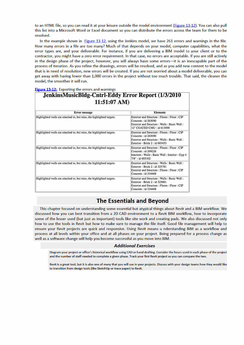
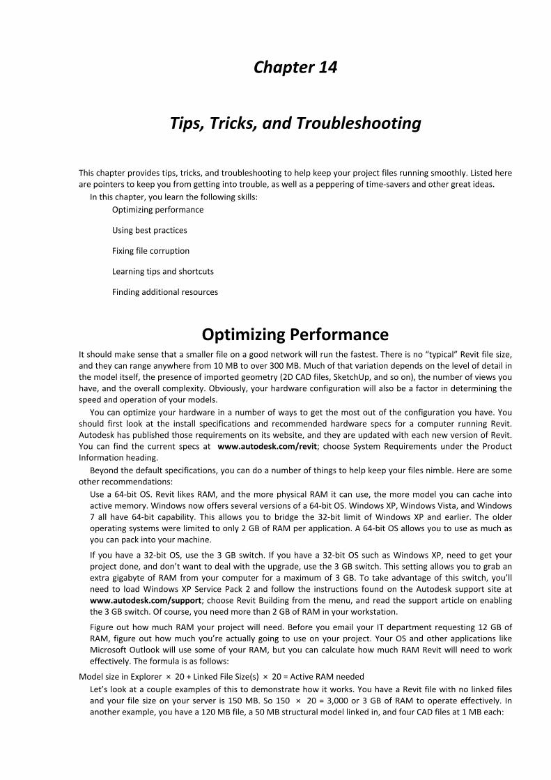
Chapter 14
Tips, Tricks, and Troubleshooting
This chapter provides tips, tricks, and troubleshooting to help keep your project files running smoothly. Listed hereare pointers to keep you from getting into trouble, as well as a peppering of time-savers and other great ideas.
In this chapter, you learn the following skills:Optimizing performance
Using best practices
Fixing file corruption
Learning tips and shortcuts
Finding additional resources
Optimizing PerformanceIt should make sense that a smaller file on a good network will run the fastest. There is no “typical” Revit file size,and they can range anywhere from 10 MB to over 300 MB. Much of that variation depends on the level of detail inthe model itself, the presence of imported geometry (2D CAD files, SketchUp, and so on), the number of views youhave, and the overall complexity. Obviously, your hardware configuration will also be a factor in determining thespeed and operation of your models.
You can optimize your hardware in a number of ways to get the most out of the configuration you have. Youshould first look at the install specifications and recommended hardware specs for a computer running Revit.Autodesk has published those requirements on its website, and they are updated with each new version of Revit.You can find the current specs at www.autodesk.com/revit; choose System Requirements under the ProductInformation heading.
Beyond the default specifications, you can do a number of things to help keep your files nimble. Here are someother recommendations:
Use a 64-bit OS. Revit likes RAM, and the more physical RAM it can use, the more model you can cache intoactive memory. Windows now offers several versions of a 64-bit OS. Windows XP, Windows Vista, and Windows7 all have 64-bit capability. This allows you to bridge the 32-bit limit of Windows XP and earlier. The olderoperating systems were limited to only 2 GB of RAM per application. A 64-bit OS allows you to use as much asyou can pack into your machine.
If you have a 32-bit OS, use the 3 GB switch. If you have a 32-bit OS such as Windows XP, need to get yourproject done, and don’t want to deal with the upgrade, use the 3 GB switch. This setting allows you to grab anextra gigabyte of RAM from your computer for a maximum of 3 GB. To take advantage of this switch, you’llneed to load Windows XP Service Pack 2 and follow the instructions found on the Autodesk support site atwww.autodesk.com/support; choose Revit Building from the menu, and read the support article on enablingthe 3 GB switch. Of course, you need more than 2 GB of RAM in your workstation.
Figure out how much RAM your project will need. Before you email your IT department requesting 12 GB ofRAM, figure out how much you’re actually going to use on your project. Your OS and other applications likeMicrosoft Outlook will use some of your RAM, but you can calculate how much RAM Revit will need to workeffectively. The formula is as follows:
Model size in Explorer × 20 + Linked File Size(s) × 20 = Active RAM neededLet’s look at a couple examples of this to demonstrate how it works. You have a Revit file with no linked filesand your file size on your server is 150 MB. So 150 × 20 = 3,000 or 3 GB of RAM to operate effectively. Inanother example, you have a 120 MB file, a 50 MB structural model linked in, and four CAD files at 1 MB each:
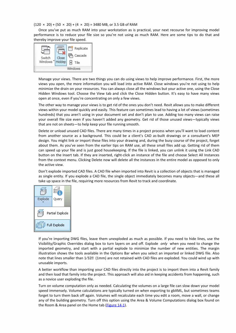
(120 × 20) + (50 × 20) + (4 × 20) = 3480 MB, or 3.5 GB of RAMOnce you’ve put as much RAM into your workstation as is practical, your next recourse for improving model
performance is to reduce your file size so you’re not using as much RAM. Here are some tips to do that andthereby improve your file speed.
Manage your views. There are two things you can do using views to help improve performance. First, the moreviews you open, the more information you will load into active RAM. Close windows you’re not using to helpminimize the drain on your resources. You can always close all the windows but your active one, using the CloseHidden Windows tool. Choose the View tab and click the Close Hidden button. It’s easy to have many viewsopen at once, even if you’re concentrating on only a few views.
The other way to manage your views is to get rid of the ones you don’t need. Revit allows you to make differentviews within your model quickly and easily. This feature can sometimes lead to having a lot of views (sometimeshundreds) that you aren’t using in your document set and don’t plan to use. Adding too many views can raiseyour overall file size even if you haven’t added any geometry. Get rid of those unused views—typically viewsthat are not on sheets—to help keep your file running smooth.
Delete or unload unused CAD files. There are many times in a project process when you’ll want to load contentfrom another source as a background. This could be a client’s CAD as-built drawings or a consultant’s MEPdesign. You might link or import these files into your drawing and, during the busy course of the project, forgetabout them. As you’ve seen from the earlier tips on RAM use, all these small files add up. Getting rid of themcan speed up your file and is just good housekeeping. If the file is linked, you can unlink it using the Link CADbutton on the Insert tab. If they are inserted, right-click an instance of the file and choose Select All Instancesfrom the context menu. Clicking Delete now will delete all the instances in the entire model as opposed to onlythe active view.
Don’t explode imported CAD files. A CAD file when imported into Revit is a collection of objects that is managedas single entity. If you explode a CAD file, the single object immediately becomes many objects—and these alltake up space in the file, requiring more resources from Revit to track and coordinate.
If you’re importing DWG files, leave them unexploded as much as possible. If you need to hide lines, use theVisibility/Graphic Overrides dialog box to turn layers on and off. Explode only when you need to change theimported geometry, and start with a partial explode to minimize the number of new entities. The marginillustration shows the tools available in the Options Bar when you select an imported or linked DWG file. Alsonote that lines smaller than 1⁄32ʺ (1mm) are not retained with CAD files are exploded. You could wind up withunusable imports.
A better workflow than importing your CAD files directly into the project is to import them into a Revit familyand then load that family into the project. This approach will also aid in keeping accidents from happening, suchas a novice user exploding the file.
Turn on volume computation only as needed. Calculating the volumes on a large file can slow down your modelspeed immensely. Volume calculations are typically turned on when exporting to gbXML, but sometimes teamsforget to turn them back off again. Volumes will recalculate each time you edit a room, move a wall, or changeany of the building geometry. Turn off this option using the Area & Volume Computations dialog box found onthe Room & Area panel on the Home tab (Figure 14-1).

Figure 14-1: Choose the area calculations to minimize unneeded computations.
Using Best PracticesGood file maintenance is critical to keeping your files running smoothly and your file sizes low. Here are some bestpractices and workflows identified in other areas of the book but consolidated here as a quick reference.
Manage the amount of information shown in views. Learn to manage the amount of information needed in agiven view. Don’t show more than you need to show in a view by working to minimize your view depth andlevel of detail. Here are some simple tips to keep your individual views working smoothly:
Minimize the level of detail. Set your detail level, found in the View Control Bar, relative to your drawingscale. For example, if you’re working on a 1⁄32ʺ (1:100) plan, you probably don’t need Detail Level set toFine. Doing so will cause the view to have a higher level of detail than the printed sheet can show, and you’llend up with not only black blobs on your sheets, but also views that are slow to open and print.Minimize view detail. Along with the amount of detail you turn on in the view using the Detail Level tool,make sure you’re not showing more than you need to. For instance, if you have wall studs shown in a 1⁄16ʺ(1:200) scale plan or the extruded aluminum window section shown in a building section, chances are it willnot represent correctly when printed. Turning off those elements in your view will keep things movingsmoother as well as printing cleaner.Minimize view depth. View depth and crop regions are great tools to enhance performance. As an example,a typical building section is shown in Figure 14-2. The default behavior causes Revit to regenerate all of themodel geometry the full depth of that view every time you open the view. To reduce the amount ofgeometry that needs to be redrawn, drag the section’s far clip plane (the green dashed line when youhighlight the section) in close to the cutting plane.
Figure 14-2: Minimizing the view depth

Model only what you need. While it is possible to model to a very small level of detail, don’t fall into the trap ofovermodeling. Be smart about what you choose to model and how much detail you plan to show. If it’s notconveying information about the project, maybe it’s not really needed. The amount of information you do or donot model should be based on your project size and complexity, your timeframe, and your comfort level withthe software.
How much to model: use these three rules of thumb. When trying to decide how much detail to put into amodel or even a family, there are three very good rules of thumb to help you make the right decision for theelement you’re looking to create.
Scale What scale will this detail be seen in? If it’s a very small-scale detail, it might be simpler to just draw itin 2D in a drafting view.Repetition How many times will this detail appear in the drawing set? If it will appear only in one location oronly one time, it might be easier to just draft it in 2D rather than try to model the element. If it will appearin several locations, modeling is probably the better solution. The more exposure an element has in themodel (the more views it shows in), the more reason you have to model it. For example, doors are good tomodel. They show in elevations and plans all over the sheet set.Quality How good at modeling families in Revit are you? Honestly? Don’t bite off more than you can chew. Ifyou’re new to Revit, keep it simple and use 2D components. The more projects you complete in Revit, thebetter you’ll understand the change to a BIM workflow.
Don’t overconstrain. Embedding user-defined constraints into families and the model help keep importantinformation constant. However, if you don’t need to lock a relationship, don’t do it. Overconstraining the modelcan cause problems later in the project process when you want to move or modify locked elements. Constrainonly when necessary. Otherwise, let the model be free.
Watch out for imported geometry. While Revit has the ability to use geometry from several other file sources,use caution when doing so. Remember that everything you link into Revit takes up about 20 times the file sizein your system’s RAM. So, linking a 60 MB NURBS-based ceiling design will equal 2 GB of RAM and more thanlikely slow down your model. Deleting unused CAD files, using linking rather than importing, and cleaning up theCAD geometry before insertion will help keep the problems to a minimum.
Purge unused files. You will find that you won’t use every family or every group you create in your model. Revithas a tool that will allow you to get rid of those unused elements to help keep your file sizes down to areasonable level. This tool, Purge Unused, can be found on the Manage tab on the Settings panel. If your file isvery large, it can take several minutes to run, but eventually you’ll be presented with a list (Figure 14-3) of allthe unused elements within your file.
Figure 14-3: Use the Purge Unused dialog box to reduce file size.

Using this tool is typically not recommended at the beginning of a project while you are still iterating variousdesign solutions and file sizes tend to be fairly small.
Model correctly from the beginning. As you refine your design, it’s critical to model correctly right from thebeginning, not taking shortcuts, so you don’t have to fix things later. If you can begin by thinking about howyour project will be assembled, it will save you a lot of time later in the process. It’s good practice to plan ahead,but remember that Revit will allow you to make major changes at any stage in the process and still maintaincoordination. If you are still in early phase of design and do not know the exact wall type, use generic walls tocapture your design intent; changing them later will be simple.
Manage workshared files. When employing worksharing on a project, there are additional tools and tips you’llwant to follow:
Make a new local copy once a week. In a workshared environment, your local copy can begin to performpoorly or grow in file size while the central file remains small and nimble. If this is the case, it might be timeto throw out the old local copy for a new one. As a general practice, if you’re accessing a project on a dailybasis, it’s a good idea to make a new local copy once a week.Divide your model. For larger projects or campus-style projects, you can break up your model into smallersubmodels that are linked together. You can also do this on a single, large building. Dividing up a modelhelps limit the amount of information you are loading into a project at one time.If you decide to divide your project, make your cuts along lines that make sense from a holistic-buildingstandpoint. Don’t think of the cuts as you would in CAD, but think about how the actual assemblies willinteract in the building. For example, don’t cut between floors 2 and 3 on a multistory building unless youhave a significant change in building form or program. Here’s a list of some good places to split a model:

At a significant change in building form or massing
At a significant change in building program
Between separate buildings on the site
At the building site
Fixing File CorruptionFrom time to time your project files will begin to experience duress and possible corruption. This can happen forany number of reasons; network problems, file size, too many errors, gremlins. If your file begins crashing, don’tpanic. There are a few things you can do before calling Revit Support. Here are some suggestions to help get youback on track:
Review warnings. Each time you create something that Revit considers a problem, a warning is issued. Warningswill accumulate if left unresolved. Think of all these errors as unresolved math calculations. The more there are,the more your computer will have to struggle to resolve them, and eventually you will have performance issuesor file instability. To review the warnings, click the Warning button on the Manage tab. You’ll get a dialog boxlike Figure 14-4, which will allow you to search for and resolve the problem objects.
Reduce your file size. Sometimes when file corruption occurs it’s due to a file that has grown beyond capacity ofthe machines using it. Reduce your file size using the previous tips to make the model more manageable andresolve some of the errors.
Figure 14-4: Resolving errors
Audit the file. Another way to deal with file corruption is to perform an audit on your file. You can find this toolin the lower-left corner of the File Open dialog box (Figure 14-5). Auditing a file will review the data structuresand try to correct any problems that have occurred. When the audit is completed, ideally you will have a fullyfunctioning file again.

Figure 14-5: Auditing a file
You can audit either a local file or the central file itself. Whenever you audit a file, you’ll want to make a newcentral copy and have all of your project team create new local copies. The last thing you want is have someonewith file corruption in a local copy synchronize those problems back to your newly fixed central file.
Learning Tips and ShortcutsBeyond all the things you can do to hone your Revit skills, you will begin to learn a number of tips and shortcuts asyour experience grows using Revit. Here is a compilation of some of those tips and tricks:
Let Revit do the math. Revit is like a big calculator and it’s very good at doing math correctly. Don’t want tospend the time trying to figure out what your room size is after you subtract a 3 5⁄8ʺ and 5⁄8ʺ piece of gypsumboard from an 11ʹ–2ʺ room? Don’t. If you need to modify a dimension, simply add an equal sign and a formula(Figure 14-6), and Revit will calculate the value for you.
Figure 14-6: Performing calculations in Revit
Add a sloped ceiling. You want to add a gypsum soffit to the bottom of a stair or you want a sloped ceiling?Well, you can’t do that with the Ceiling tool. But you can with a ramp. Make a gypsum board ramp and align itto the bottom of your stair or angle it to create your sloped ceiling plane.
Make elevators visible in your plans. You want to create a shaft that will penetrate all the floors of your buildingand put an elevator in it that will show in all your plans. You could do this with an elevator family and cut aseries of holes in the floors by editing floor profiles, but sometimes those holes stop aligning on their ownrecognizance. Fortunately, you can do both things at once using the Shaft tool found on the Opening panel ofthe Home tab. Here, you can not only cut a vertical hole through multiple floors as a single object, but you canalso insert 2D linework to represent your elevator in plan (Figure 14-7). Every time the shaft is cut, you’recertain to see the elevator linework.
Figure 14-7: Adding elevators to a shaft

Orient to view. Creating perspective views of isolated design elements can be quick and easy in plan or section,but let’s say you want to see that same element in 3D to be able to work out the details.
1. Create a plan region or section cut isolating the area in question. If you’re using a section, make sure to setyour view depth to something practical.2. Open the default 3D view or any axon of the project.3. Right-click the ViewCube, select Orient To View, and select your view from the context menu4. Now your 3D view will look identical to your section or plan region, but by rotating the view, you’ll be able tosee that portion in 3D.Tune your shortcuts. Revit now allows you to edit your keyboard shortcuts without the hassle of rootingthrough your hard drive looking for a TXT file. To edit your shortcuts, click the Application menu and selectOptions. Choose the User Interface tab and then the Customize button. The Keyboard Shortcuts dialog box(Figure 14-8) allows you to edit those shortcuts. Consider making common shortcuts the same letter. So,instead of pressing VG to get to your Visibility/Graphic Overrides dialog box, make the shortcut VV for quickeraccess.
Figure 14-8: Editing your keyboard shortcuts

Drag and drop families. You need to load a family into Revit, you have the Explorer window open, and you knowwhere the family is, but you don’t want to go through the laborious effort of navigating across your office’sserver environment to get there. No problem. You can drag and drop Revit families from Explorer directly intothe project file.
Copy a 3D view. You made the perfect 3D view in your last project, and you can’t figure out how to get it intoyour current project. Fortunately, there’s a way to copy views from one project to another. Open both files inthe same instance of Revit.
1. In your perfect view, right-click the 3D view in the Project Browser and choose Show Camera from thecontext menu.2. Press Ctrl+C to copy the selected camera.3. In your new model, use Ctrl+V to paste the camera and your view and all its settings are now there.Use a quick cut poche. Want to change everything that’s cut in a view without having to select every family andchange its properties? A quick cut poche is, well, quick:
1. Open the view you want to modify.2. Using a crossing window, select all the elements within the view.3. Right-click and choose Override Graphics ⇒ By View from the context menu. As shown in Figure 14-9, youcan choose any filled region in the project and assign it to anything that is cut within your model.
Figure 14-9: Using Override Graphics for a quick poche


Appendix: Revit Certification
Autodesk certifications are industry-recognized credentials that can help you succeed in your designcareer—providing benefits to both you and your employer. Getting certified is a reliable validation of skills andknowledge, and it can lead to accelerated professional development, improved productivity, and enhancedcredibility.
This Autodesk Official Training Guide can be an effective component of your exam preparation. Autodesk highlyrecommends (and we agree!) that you schedule regular time to prepare, review the most current exampreparation roadmap available at www.autodesk.com/certification, use Autodesk Official Training Guides, take aclass at an Authorized Training Center (find ATCs near you here: www.autodesk.com/atc), take an Assessmenttest, and use a variety of resources to prepare for your certification—including plenty of actual hands-onexperience.
To help you focus your studies on the skills you’ll need for these exams, the following tables show the objectiveand in what chapter you can find information on that topic—and when you go to that chapter, you’ll findcertification icons like the one in the margin here.
Table A-1 is for the Autodesk Certified Associate Exam and lists the topic, exam objectives, and chapter wherethe information is found. Table A-2 is for the Autodesk Certified Professional Exam. The topics and exam objectiveslisted in the table are from the Autodesk Certification Exam Guide.
These Autodesk exam objectives were accurate at press time; please refer to www.autodesk.com/certificationfor the most current exam roadmap and objectives.
Good luck preparing for your certification!
Table A-1 Certified Associate Exam Topics and ObjectivesTopic Exam Objectives Revit Essentials
Collaboration Use work sharing Chapter 10
Import DWG files into Revit Chapter 13
Documentation Create and modify filled regions Chapter 11
Place detail components and repeating details Chapter 11
Use dimension strings Chapter 11
Set the colors used in a color scheme legend Chapter 9
Elements Create a stacked wall Chapter 3
Differentiate system and component families Chapter 6
Modify an element’s type parameters Chapter 7
Use Revit family templates Chapter 6
Modeling Create a building pad Chapter 13
Define floors for a mass Chapter 2
Create a stair with a landing Chapter 5
Generate a top surface Chapter 13
Model railings Chapter 5

Edit a model element’s material (door, window,furniture)
Chapters 3, 7
Change a generic floor/ceiling/roof to a specific type Chapter 3
Attach walls to a roof or ceiling Chapter 3
Views Define element properties in a schedule Chapter 12
Control visibility Chapters 1, 7
Use levels Chapter 2
Create and manage legends Chapter 12
Manage view position on sheets Chapter 12
Move the view title independently of the view Chapter 12
Organize and sort items in a schedule Chapter 12
Table A-2 Certified Professional Exam Topics and ObjectivesTopic Exam Objectives Revit Essentials
Collaboration Copy and monitor elements in a linked file Not Covered
Import DWG files into Revit Chapter 13
Documentation Tag elements (doors, windows, etc.) by category
Chapter 6
Elements Change elements within a curtain wall (grids,panels, mullions)
Chapter 3
Create compound walls Chapter 3
Create a stacked wall Chapter 3
Create and modify family categories Chapters 6, 7
Create a new family type Chapter 7
Modeling Assess review warnings in Revit Chapters 13, 14
Define floors for a mass Chapter 2
Create a stair with a landing Chapter 5
Create elements such as floors, ceilings, or roofs
Chapters 3, 4
Generate a top surface Chapter 13
Model railings Chapter 5
Work with phases Chapter 8
Attach walls to a roof or ceiling Chapter 3
Views Control visibility Chapters 1, 7
Use levels Chapter 2

Create a duplicate view for a plan, section, ationelev, drafting view, etc.
Chapter 1
Create and manage legends Chapter 12
Table A-1 Certified Associate Exam Topics and Objectives (Continued)(Continues)
Table A-2 Certified Professional Exam Topics and Objectives (Continued)

Index
A
accessoriesActivate View commandactivating
commandsviews
active viewsdisplayingpropertiesvisibility
active worksetsAdd Edge toolAdd Leader buttonAdd Parameter optionAdd Points From Selected Layers dialog boxAdd/Remove Segments optionAdd Split Line optionAdd Vertical/Horizontal Segments option, railingsAdditional Copy Parameters settingsAdditional Settings option, viewsAdditional Settings panelAECbytes websiteAlign tool
dimensionslights
Aligned To Selected Levels optionAligned To Selected Views optionAligned toolaligning
copyingdimensionselementslightsshaftsviews on sheetswindows
Alignment settingAngled Joins optionAnnotation Categories tabannotations and Annotate tab
blockingcomponentsdimensionsfamiliesfilled regionsgroupsinsulationlines

regionsrepeating detailstagstext
Appearance tabscheduleswalls
Arc toolarchitects role in BIM workflowArchitectural annotationsArea & Volume Computations dialog boxArrange panelarranging elementsArray toolarrays
creatingoptions
arrowheads for tagsarrows, slope
building padsceilingsfloors
assigningelements to worksetsmaterials
associating linked filesAttach Top/Base optionattached relationships with wallsattaching walls
to rooftop and base
auditing filesAUGI (Autodesk User Group International)Autodesk Seek panelautomatic ceilingsautomatic snapping
B
background imagesBaluster Offset optionBaluster Placement optionBaluster-Square optionbalusters
editinglevel of detailsettings
Base Constraint parameterBase Is Attached parameterbase masses, modelingBase Offset setting
ceilingswalls
baseboards

basement floor plansBasic Wall Generic - 6” optionBasic Wall Nodebasic wallsbatt insulationBegins With filter conditionbest practicesBIM (building information modeling) approach
overviewproject rolesstaffingteam members
black colorlevelslinksramp linesseparation lines
blocksinserting and placingtitle
creatingplacing
for toposurfacesblue color
cut symbolsdimensionslevelslinksnodesramp linesschedulestags
Bond Beam detail componentBoolean queriesborrowed elements
central filesdisplaying
borrowing elementsboundaries
building padsceilingseditingfilled regionsfloorsrampsroomsschedules
Boundary toolbreak lines
detail componentseditingstairs
Break Symbol option

breaking schedulesBrick componentbrick and mortar componentsbrick repeating detailBrick Standard componentBring Forward optionBring To Front optionBuild panelBuilding Elevation viewbuilding information modeling (BIM) approach
overviewproject rolesstaffingteams members
building padsbulkhead conditionsBy Face toolBy View tool
C
CAD-based projectsCAD files
deleting and unloadingexploding
Calculate Totals optionmass floorsschedules
calculationsperformingvolume
Callout toolCarriage Heights optioncase sensitivity of queriescategories
familiesschedules
Categories And Types To Copy listCeiling toolceilings
automaticbulkhead conditionschanginglights and gridssketchingsloped
cellscentral files
avoidingcreatingsaving to
CFD (computational fluid dynamics) modelchain-select methodchains of elements

linesselectingwalls
chairs, placingChoose Space Type and Color Scheme dialog box, circles for toposurfacesCirculation fillclipboard, copying toClipboard panelClose Hidden optionClose Hidden Windows toolclosing
hidden windowsworksets
CMU elementCoarse detail levelcode requirements, architects forcoffee tableCollaborate tab
consultantssynchronizationworkset access
collections. See groupscolor
cut symbolsdashed linesdemolished wallsdimensionslevelslineslinksnodesramp linesschedulesseparation linestags
Color fieldcolor fill plans
legendssections
columnscommands, activatingcompleted viewsComponent menuComponent toolcomponents
detail. See details and detail levelsfamilies. See familieshosted. See hosted componentsinserting
Compress optioncomputational fluid dynamics (CFD) modelcomputations

performingvolume
conflicts, errors and warnings forConstrain optionconstraints
alignmentoverconstrainingwalls
consultantscontainers, worksets ascontent, team member additions forcontour polylines for toposurfacesCopy/Monitor Options dialog boxCopy/Monitor toolCopy tool
groupslevels
Copy To Clipboard toolcopying
3D viewsalignedcentral filesfill patternsgroupslevelslocal files
core worksetsCorner Post baluster optioncorrupted files
causesfixing
Count fieldCreate Detail Group dialog boxCreate Form toolCreate From Import optionCreate Group toolCreate New Local optionCreate Similar toolCreate Solid optioncrop regionsCrop toolcrop windows and tagscrossing railing linesCurrent Window optionCurtain Grid toolcurtain panel doorscurtain walls
elevation profilesembeddinggrid linesmasses for hostingmullionspanels

selectingtypes
curved curtain wall panelscut symbolscutting wall openings
D
dashed lines for planesdatums
adjustinggroups
daylightingDeactivate View commanddeactivating viewsdeadlinesDefault 3D View iconDefault Wall materialdefaults
3D viewceilingscolor assignmentshandrailsinsertion pointslinesmullionsnamesrailingsstair runstemplatestitle blockswall placement
Defines Origin optionDefines Slope optiondeleting
CAD filesconstraintshostslevelsmullionsschedule rowstagswall openings
Demolish tooldemolition elementsdepth, viewsdesks
family level of detailplacing
Detach From Central optiondetaching wall top and baseDetail Component familyDetail Component optionDetail Group menu

Detail Level toolDetail Line toolDetail Line toolsetDetail rotation optiondetails and detail levels
annotatingarranging elements in viewscomponentscreatingdimensionseditingfamilies
displayediting
groupsinsulationlegendslinework
descriptionworking with
minimizingmodeling decisionsregionsrepeating
creatingdescriptioneditingrules of thumb
scalingskills fortagsteam member additions fortext
Diagonal Crosshatch optiondimensions
addingaligningcurtain wallsdrafters forgrid linesreference planeswalls
Disallow Join optiondisplay filters
phaseschedules
descriptionSheet List
worksetsdividing linesdividing modelsDo Not Save The Project optionDon’t Copy This Type option

Door tooldoors
curtain paneldemolition elementsplacingin walls
Doors And Windows settingdrafters role in BIM workflowdrag and drop familiesDraw panel
arcsPick Lines iconshapesslope arrows
drawing setsplacing views
floor plansschedules
printing documentsschedules. See schedules
Duplicate optionduplicating
componentsgroupshandrailswalls
E
edgesceilingsmassesviews
Edit Assembly dialog boxceilingswalls
Edit Baluster Placement dialog boxEdit Boundary option
ceilingsfloors
Edit Color Scheme dialog boxEdit Extrusion tool
glazinghosted components
Edit Family optionlevel of detailtitle blocks
Edit Group modeEdit Group optionEdit Group panelEdit In-Place buttonEdit Profile option
elevationwall profiles

Edit Rails dialog boxEdit Rails optionEdit Scheme toolEdit Surface ribbonEdit Type option
detaildimensionsfilled regionsrailingsrepeating detailsstairstagswalls
editingceiling boundariesceilingscolor legendsdefault color assignmentsdetailsfamiliesfloor boundariesgroupsinsertion pointsrailsramp boundary conditionsrepeating detailsshortcutswall profiles
Element Properties optionelements
aligningarrangingassigning to worksetsborrowingchains of
linesselectingwalls
creatingdemolition and proposedtypeswall
Elevation Of Poche Base settingselevations
BIM modelscurtain wallsdatums forenteringpochesscales
elevatorselliptical wallsembedding curtain walls

enabling worksharingEnd Post baluster optionEQ setting
dimensionsgrid linesprofile linesreference planes
equal signs (=) in formulaserrors and warningsErrors And Warnings dialog boxErrors And Warnings toolEsc keyexchanging groupsExisting phaseexploding imported CAD filesExport featureexporting
errors and warningsto gbXML
Extend Below Base optionExtend Rails To Meet optionextensions, handrailExterior - Brick and CMU on Mtl. Stud wallExterior - Brick on Mtl. Stud wallExterior Elevation viewExterior wallsexterior worksetsextruded roofsExtrusion End settingextrusions
F
face-based familiesgeometric contextswith multiple hostsoverview
facesfloor areain-place masseswalls
familiesannotationscategories and parametersdetail componentsdetail level
displayediting
drag and dropeditingface-basedhosted
editingoverview
insertion pointslegendslevel-basedloadingoriginsparametersplacingprofiles
associatingediting
purgingrepeating details
descriptionediting
title blocksdescriptionediting
typesview displaywindow schedules
Family Category And Parameters dialog box, 164, Family Editor
balusterscomponent familiesdeskshosted componentsprofiles
Family Element Visibility Settings dialog box, 161, Family Types dialog boxfence postsfields and Fields tab
mass floorsroom keysschedules
Sheet Listwindowsworking with
File Open dialog boxfiles
associatingauditingcentral
avoidingcreatingsaving to
corruptedcausesfixing
deleting and unloadingexplodinglocal
creatingsaving

purgingsavingsize
Fill available Space modefill color
legendssections
Fill Patterns dialog boxFill Patterns optionFilled Region commandfilled regions
addingboundariesdescription
Fillet Arc toolfilling brick patternsFilter dialog box
wallsworksets
Filter tabpurposeSheet List
Filter toolfilters
phaseschedules
descriptionSheet List
wall selectionsworksets
Fine detail levelFinish Edit Mode buttonFinish Face settingFinish Mass toolFinish Sketch Mode optionfinishes
stairswalls
Fixed Distance modeFixed Number modeflashingflexing window typesFloor Area fieldFloor Plan optionfloor slabsFloor toolfloors
boundariescopying and monitoringfloor plansmass
creatingscheduling

monitoringopenings
with shaftsby sketching
sketchingsloped
creatingshape editing for
sloped arrowswalls for
Floors tabfonts
schedulestext
Formatting tabmass floorsschedules
formulascalculationserrors and warningsheight
foundation wallsFrame/Mullion Extrusion optionframes, windowsFunction parameter
stairswalls
furniture, overconstrainingFurniture System Tag optionFurniture tag
G
G000 Cover Sheetgaps
floorsrailingswindow sill
Generic - 12” floor typegeneric elements
designingrailingswalls
Generic Models tabGeographic information system (GIS) datageometric contextsgeometry
errors and warningsimportedroofs
Geometry panelgeometry phasesGIS (geographic information system) data

glazingBIM modelswindows
Google SketchUp toolGraphics tabgrayed out viewsgreen dashed linesGrid Visibility parametergrids
ceilingscopying and monitoringcurtain wallsdatums forgroupsrotatingschedulestitle blocks
gross floor areaGroup And Associate optionGroup Parameter Under optionGroup toolgroups
best practiceschairscopyingcreatingdefineddetailsduplicatingeditingexchangingand imagesloadingoverviewpurgingreplacingsavingschedules
groutGWB on Mtl. Stud Ceilinggypsum board
ceilingsdimensions
Gypsum Wall Board material
H
Handrail - Design settinghandrails
creatingprofiles
heightceilingsformulas

imagesmassesrailingsroofsstair elementsstringerswindows
Height fieldimageswindow schedules
Height Offset At Head settingceilingsrailingsroofs
Height Offset At Tail settingceilingsrailingsroofs
help, resources forHidden Line modehidden lineshidden windowsHide Crop Boundaries optionHide ref/Work planes optionHide Scope Boxes optionHide Unreferenced View tags optionHighlight In Model featureHome tab
ceilingscolor legendsdatumsdoorsfamiliesfill patternsfloorslevelslinesmasking regionsrailingsrampsreference planesroofsroom tagsshaftsstairsvolume computationwalls
Host Length optionhosted components
editinggeometric contextsgroupslegends

overviewrailingswall elements
hyphens (-) in names
I
Image Placement toolimages
backgroundand groupsscaling
Import Panelimported data
explodinggeometrytoposurfaces from
importing background imagesIn-Place Editor panelin-place masses
3Dbassmiddleupper
In-Place Masses toolInclude Elements In Linked Files optionIndividual Owners optioninserting and Insert tab
blockingCAD filescomponentscurtain panel doorsfamiliesgroupsimageslightslinks
insertion pointsfamiliesgroups
Inside option for repeating detailsinstance parametersinsulationInsulation toolinterface
Options BarProject BrowserProperties palettestatus barView Control BarViewCubeworkflow
datumslayout

modifying toolsInterior - Partition wallsinterior worksetsiPadiPhoneisolating wallsItemize Every Instance option
J
Jenkins modelJohnson, LukeJoin toolJoin/Unjoin Roof optionjoined roofsjoining massesjoins, railings
K
Key Name fieldkeyboard shortcutsKeyboard Shortcuts dialog boxkeynote legendskeynoting, drafters forkeys, roomsKhemlani, Lachmi
L
L Shaped Handrail profile familylabelingLanding Height Adjustment settinglandings
exercisessettingsstraight run with
layoutscreatingrepeating details
leaderstagstext
left and right options vs. mirroringLegend Components settingsLegend toollegends
addingcolor
lengthhostswalls
level of detail in familiesmodifyingoverview
level railingsLevel tool
sketchesstairs
levelsbuilding padsconstraintsdatums forgroupssketchesstairsworksharing
libraries for categorieslights, ceilingsLine Color optionLine Style optionLine Style panelLine Styles optionLine Styles Type Selector panelLine tool
blockingtitle blocks
linear paths for repeating detailslines
blockingdetailgrid. See gridshiddenrailingsrampsseparationsplittitle blocksviewswalls
Lines toollinework
descriptionworking with
Linework toollinked files, associatinglinksLoad As Group optionLoad Families buttonLoad Family optionLoad From Library panelLoad Into Project buttonloading
familiesgroups
local copieslimitingsaving

local filesLocation Line parameterLocation Line to Finish Face settingLock 3D View toollock symbollocking
alignmentdimensions
M
Main Baluster Pattern optionMake Plan View optionManage tab
aligning elementsdemolition elementserrors and warningsfill patternsprintingpurgesroom separation linestitle blocksviews
Masking Region toolmasking regionsmasonrymass floors
creatingscheduling
Mass Floors toolmasses
in-place3Dbassmiddleupper
joiningmassing studiessketching
Massing & Site tabMaterial Tag buttonMaterial tagsmaterials
stairstakeoff scheduleswalls
mathMaximum Incline Length settingMaximum Spacing modeMeasure toolmeasuring imported imagesMedium detail levelmemory requirements
determining

imported geometrymetal deckingmiddle mass modelingMirror - Pick Axis toolmirroring
limitationsprocess
Mode paletteModel Groups tabModel Line toolModel Site panelmodelers in BIM workflowmodeling
in-place masses3Dbassmiddleupper
sitesbuilding padstoposurfaces
models, dividingModify panelModify tab
aligning elementselevationsgroupsjoinslevelslineworkmirroringrailingssplitting
modifying toolsaligned copying and group editingaligning elementsdimensionsrotating, grouping, and arraying
modifying wallsMonitor commandMonolithic stair familymouse, zooming and panning withMove Down optionMove To optionMove Up optionmoving
grid linesribbonview tagswalls
Mullion toolmullions
adding

unpinning and togglingMulti-Category schedulesMultiple optionmultistory shaftsmultistory stair runsMultistory Top Level settingmultiuser workflow. See worksharing
N
Name dialog boxName fieldnames
groupshandrailsin-place masseslevelsroom keystypes
Navigation barnesting groupsNew Legend View dialog boxNew option for room keysNew Only optionNew Schedule dialog box
mass floorssettings
New Schedule menuNew Sheet dialog boxNew Sheet optionNew Subcategory dialog boxNo Connector optionNosing ProfilesnosingsNote Block schedulesnumber of views reductions
O
Object Styles dialog boxoffsets, balusterOpaque/Transparent settingOpen In Group Editoropening
projectsworksets
openingsfloors
with shaftsby sketching
wallsoperating systemsoptimizing performanceOptions Bar

Options pane for printingOrient To View optionorientation of familiesorigin of familiesoverconstraining
furnitureproblems from
overlapping lines for railingsoverlapping massesOverwrite The Existing Version optionownership status
P
panning with mouseParameter Properties dialog boxparameters
detail componentsrailingsrampsreference planesstairstitle blockswalls
parametric modelsparapet capsparking spacesPaste Aligned commandPaste toolperformance, optimizingperspectives in BIM modelsPhase Created propertiesPhase Demolished propertiesphasing
completed viewsdemolition and proposed elementsgeometryviews
Phasing panelPick Lines modePick Lines toolPick New Host toolPick Wall toolpicking wallspinned mullionsPlace A Component optionPlace Component menuPlace Component tabPlace Detail Component tabPlace Detail Group buttonPlace Detail Lines menuPlace Lines tabPlace On Face optionPlacement panel
placingblockingdesks and chairsfamiliestitle blocksviews on sheets
floor plansschedules
windowsPlan Views optionplans in BIM modelspoches, quick cutpolylines for toposurfacespredictability in BIM modelspreloaded annotationspreloaded profilesPrevious + New optionPrint commandPrint dialog box
hidden linesOptions panePrint Range
Print Range settingPrint Setup dialog boxPrinter control panelProduct Information headingprofiles
elevationfamilies
associatingediting
wallsProject Browserproject roles in BIM workflowproject templatesprojects, openingProperties palette
balustersbuilding padsconstraintscrop windowsdimensionsfamiliesfilled patternsgridsgroupslevelsoffsetsrailingsrampsregionsrepeated detailselected walls
slopesstairstagsType SelectorView Control Barwallswindowsworksets
proposed elementsProposed phasePurge Unused dialog boxPurge Unused toolpurging
families and groupsfiles
Q
QAT. See Quick Access toolbar (QAT)quality control
errors and warningsfile sizepurging unused families and groupsrules of thumbviews
Quick Access toolbar (QAT)3D viewsdimensionshidden windowsmeasurementssection tools
quick cut poches
R
Rail Structure optionRailing toolrailings
generichost functionlevel and sloped conditionsparametersprofilestools
Railings Type optionRAM requirements
determiningimported geometry
Ramp Max Slope settingRamp toolramps
boundary conditionsparametersstraight runs
raster processingRectangle toolRectangular Handrail familyred color for demolished wallsRef Plane toolreference planes
creatingdatums forhosted componentssketches
regionsfilled
addingboundariesdescription
maskingRelinquish All Mine optionrelinquishing elements and worksetsReload option for groupsReload Latest optionrenaming
handrailstypes
Render Appearance tabRendered setting for wallsRendering Show/Hide toolRepeating Detail commandRepeating Detail Component toolrepeating details
creatingdescriptioneditingrules of thumb
repetitive relationshipsreplacing groupsReset Profile optionresetting wall profilesresources, RevitReveal Hidden Elements toolRevit Help menuRevit ProfessionalsRevitCity siteribbonright and left options vs. mirroringRisers optionRoof By Extrusion commandRoof By Footprint optionRoof toolroofs
extrudedmasses for hostingwalls for
Room & Area palette

Room & Area panelRoom Bounding parameterRoom functionRoom Separation Line optionRoom Tag optionRoom Tag With Area optionRoom toolrooms
boundariescolor fill plans
legendssections
keysschedulesseparation linestagsand walls
Rotate toolrotating.rvt extension
S
Sand - Dense fill patternSave Group optionsaving
to central filefilesgroupslocal copiesprint settings
Scale toolscales and scaling
detailingelevationfamiliesimagesrules of thumbstair runs
Schedule Keys optionSchedule Properties dialog box
Appearance tabbuttonsFields tabFilter tabFormatting tabmass floorsroomsSorting/Grouping tabwindows
Schedule/Quantity buttonSchedule/Quantity schedulesSchedule tab
buttons

room fieldsschedules
adding to sheetsBIM modelsbreakingcategoriesdrafters forerrors and warningsfamily categories formass floorsroomsSheet Listtypeswindows
Schedules menuschematic design
drafters forin-place masses
3Dbassmiddleupper
mass floorsmassing studiessketches. See sketches
section boxesSection Cut Material optionSection toolsections
BIM modelsstairstags and fill colors in
Select All Instances optionSelect Import Instance optionSelect Items To Copy dialog boxSelect Levels dialog boxSelected Views/Sheets optionSend Backward optionSend To Back optionseparation linesseries of wallsSet Host function7 Max Riser 11” Tread stair familyShaded modeShaded With Edges modeShading settingShadows toolShaft tool
elevatorsfloors
shaftselevatorsfloors openings with

shape editing for sloped floorsShape Editing toolsshape handles
editingwalls
Sheet Composition panelSheet iconSheet List Properties dialog boxSheet List schedulesSheet Name, sorting bySheet Number, sorting bysheetrocksheets
drafters forplacing views on
floor plansschedules
shortcuts, keyboardShow All optionShow Camera optionShow Categories From All Disciplines optionShow Complete optionShow/Hide Crop toolShow Mass optionShow New optionShow Previous + Demo optionShow Previous Phase optionshrubsSimplify Surface buttonsite modeling
building padstoposurfaces
Site Settings dialog box64-bit OSsize
filesschedule text
Sketch mode for roofsSketchBook Pro toolsketches
background imagesceilingsfloors
creatingopenings
groupsmassesreference planes and levelsscaling imageswalls
Slope Arrow toolslope arrows
building pads

ceilingsfloors
sloped ceilingssloped floors
creatingshape editing for
sloped railingssloped roofssnappingsolar gain in BIM modelsSort By settingSorting/Grouping tab
mass floorsschedules
creatingsettingsSheet List
Sound Transmission Class (STC)spacing
repeated detailswalls
Spacing optionSpecialty Equipment optionSplit Element toolsplit linessplitting wallsstacked wallsstaffing BIM projectsStair Carriages optionstairs
balusterseditinglevel of detailsettings
exerciseslevel of detailmultistory runsparametersrailings
generichost function
scalingstraight runstraight run with landingtools
Stairs toolStart Post baluster optionstatus, ownershipstatus barStorefront curtain wallsstraight run rampsstraight run stairsstraight run with landing stairs

Stringer Height optionstringers, stairsstrings, dimensionsubscription supportSun Path toolswapping wallsSWC (Synchronize With Central)Switch Windows commandSynchronize And Modify Settings optionSynchronize Now optionSynchronize panelSynchronize With Central (SWC)Synchronize With Central dialog boxSystem Requirements option
T
Tab key for wall referencestables
coffeeplacing
Tag All Not Tagged dialog boxTag All Not Tagged optionTag By Category optionTag On Placement buttonTag paneltags
addingannotationsroomssectionstext in
Tangent Arc tooltangent arcs
creatingramps
Tangent Joins optionteams, BIMtemplates, projectTemporary Dimension Propertiestemporary dimensions
curtain wallssetting
Temporary Hide/Isolate tooltext
addingdimensionsschedulesstairstags
Text Font optionsText paletteText Size optionsText tab

Text toolthickness of building pads3 GB switch3D views
3D Cutawaycopyingin-place masses
30 Degree Arrow option32-bit OStiled windowstitle blocks
creatingplacing
toggling mullionstop and base of wallsTop Constraint parameter
roofwalls
Top Is Attached parameterTop Offset settingtoposurfaces
descriptionsfrom imported data
Transfer Project Standards tooltransparent backgrounds for dimensionsTreads optiontreesTrim toolTrim/Extend To Corner tooltrimmed railings2D annotationsType fieldType Mark fieldType Properties dialog box
dimensionsgridsnamesrailingsrampsregionsrepeating detailsstairswalls
Type Selectorblockingceilingsdetailslightswalls
U
Unconnected Height parameterunderscores (_) in names

ungrouping groupsUnjoin Walls optionunloading unused CAD filesunpinning mullionsunreferenced view tagsunused families and groupsunused filesUpdates optionupdating
color legendsmassing studiesroom keys
upper mass modelingUser Interface tab
V
vector processingvehiclesvertices for in-place massesView Control BarView Links in Blue optionView List schedulesView optionView Phase settingView/Sheet Set dialog boxViewCube
floor plansOrient To Viewrotating
views and View tabactivatingarranging elements incompleteddeactivatingdepthdisplayingdrafters forfamilieshidden viewshidden windowslegendslimitinglinesmanagingmass floorsphasesplacing on sheets
floor plansschedules
Plan Viewspropertiesvs. reference levelsroom keys

schedulestagstiled windowstitle blocksvisibility
visibility and Visibility/Graphic Overrides dialog boxbalusterselevatorsfamily parametersfamily profilesgridshosted componentslayersprint rangesshortcutsworksets
Visibility Setting columnVisible portion Of Current Window optionVisual Style toolvolume computation
W
Wall Centerlines settingWall Opening optionwall studsWall toolwalls
attached relationships withbasicchain-select methodconstraintscopying and monitoringcurtain. See curtain wallsdemolition elementsdimensionsellipticalfaces forfinishesfor floorsfoundationgenericheighthosting elementsinstance parametersisolatinglegendsmasses for hostingmodifyingmovingopeningspickingplacingprofiles

for roofsshape handlessketchingspacessplittingstackedswappingtop and basetype changes
Walls tabopeningsprofilesworksharing
warningsceilingsfindinglevel deletionsreviewingtags
welded railingsWide Lines optionwidth settings
family profilesinsulationwindow schedules
window sillcreatingdimensionsrepeating details
Window tagswindows
framesglazingplacingschedules
adding to sheetscreating
tiledin walls
Wireframe buttonWireframe modewireframesWork Plane panelworkflow
BIMoverviewproject rolesstaffingteam members
interfacedatumslayoutmodifying tools
working viewsWorkset Assignments tabworksets and Worksets dialog box
addingassigning elements toborrowed elementsas containersdisplay filtersopening and closingownership statussettingsvisibility
Worksets optionWorksets paletteworkshared filesworksharing
central filesavoidingcreatingsaving to
consultantsdisplay settingelementsenablingguidelineslocal files
creatingsaving
saving to central fileworksets. See worksets and Worksets dialog box
Worksharing dialog boxWorksharing Display Off optionWorksharing Display Setting dialog box
Y
YouTube
Z
zero error requirementsZoom All To Fit optionZoom Sheet Size optionZoom To Fit optionzooming with mouse