Switch Mode Power Supply S8VK-T (120/240/480/960 W · PDF fileSwitch Mode Power Supply S8VK-T...
18
1 New Product Switch Mode Power Supply S8VK-T (120/240/480/960 W Models) Worldwide 3-phase Power Supply Resistant in tough environments Easy and fast installation The most compact class on the market • Wide input range for worldwide applications: 380 to 480 VAC (320 to 576 VAC) • Possible for 2-phase input usage: 380 to 480 VAC (340 to 576 VAC) • DC input can be available*: 450 to 600 VDC (450 to 810 VDC) * Excluding 960 W • High efficiency 91% typ. at 480 W model • Wide operation temperature range: –40 to 70°C • Power Boost function at 120% • Meets LR maritime standards • EMS: Conforms to EN 61204-3 EMI: EN61204-3 Class B • RoHS Compliant Model Number Structure Model Number Legend Ordering Information Note: For details on normal stock models, contact your nearest OMRON representative. Power ratings Input voltage Output Voltage Output current Boost Current Model number 120 W 2-phase and 3-phase 380 to 480 VAC 450 to 600 VDC 24 V 5 A 6 A S8VK-T12024 240 W 24 V 10 A 12 A S8VK-T24024 480 W 24 V 20 A 24 A S8VK-T48024 960 W 2-phase and 3-phase 380 to 480 VAC 24 V 40 A 48 A S8VK-T96024 ! Refer to Safety Precautions for All Power Supplies and Safety Precautions on page 12. 1 2 S8VK- T@@@@@ 1. Power Ratings 120: 120 W 240: 240 W 480: 480 W 960: 960 W 2. Output voltage 24: 24 V
Transcript of Switch Mode Power Supply S8VK-T (120/240/480/960 W · PDF fileSwitch Mode Power Supply S8VK-T...

1
New Product
Switch Mode Power Supply
S8VK-T (120/240/480/960 W Models)
Worldwide 3-phase Power SupplyResistant in tough environmentsEasy and fast installationThe most compact class on the market
• Wide input range for worldwide applications: 380 to 480 VAC (320 to 576 VAC)
• Possible for 2-phase input usage: 380 to 480 VAC (340 to 576 VAC)
• DC input can be available*:450 to 600 VDC (450 to 810 VDC)* Excluding 960 W
• High efficiency 91% typ. at 480 W model• Wide operation temperature range: –40 to 70°C• Power Boost function at 120%• Meets LR maritime standards• EMS: Conforms to EN 61204-3
EMI: EN61204-3 Class B• RoHS Compliant
Model Number StructureModel Number Legend
Ordering InformationNote: For details on normal stock models, contact your nearest OMRON representative.
Power ratings Input voltage Output Voltage Output current Boost Current Model number
120 W 2-phase and 3-phase380 to 480 VAC450 to 600 VDC
24 V 5 A 6 A S8VK-T12024
240 W 24 V 10 A 12 A S8VK-T24024
480 W 24 V 20 A 24 A S8VK-T48024
960 W 2-phase and 3-phase380 to 480 VAC 24 V 40 A 48 A S8VK-T96024
! Refer to Safety Precautions for All Power Supplies and Safety Precautions on page 12.
1 2S8VK- T@@@@@
1. Power Ratings120: 120 W240: 240 W480: 480 W960: 960 W
2. Output voltage24: 24 V

S8VK-T
2
SpecificationsRatings, Characteristics, and Functions
*1. Do not use an inverter output for the Power Supply. Inverters with an output frequency of 50/60 Hz are available, but the rise in the internal temperature of the Power Supply may result in ignition or burning.
*2. For a cold start at 25C. Refer to Engineering Data on page 6 for details.
*3. If the output voltage adjuster (V. ADJ) is turned, the voltage will increase by more than 29.5 VDC of the voltage adjustment range.When adjusting the output voltage, confirm the actual output voltage from the Power Supply and be sure that the load is not damaged.
*4. A characteristic when the ambient operating temperature is between –25 to 70°C.
*5. Refer to Overvoltage Protection on page 8 for the time when input voltage shuts off and input turns on again.
*6. To meet safety standards, the S8VK-T must be protected with an external circuit-breaker or a fuse. Be sure to use an external circuit-breaker or a fuse. Refer to Precautions for Safe Use on page 13 for details.
*7. Model FAZ-C1/3, EATON INDUSTRIES (AUSTRIA) GMBH (E177451) and Model KLKD5, LITTELFUSE INC. (E10480) of the Supplementary Fuse/Circuit Breaker must be installed in accordance with NEC.
*8. Safety Standards for a DC InputThe following safety standards apply to a DC input: UL 60950-1, EN 50178, and EN 60950-1.
*9. In the case of using side-mounting bracket (S82Y-VK10S, S82Y-VK20S), Lloyd's Standards are not applicable.
*10.The value is when both rated output voltage and rated output current are satisfied.
*11.380 to 480 VAC input, in the range of 0 A to the rated output current
Power rating 120 W 240 WItem Output voltage 24 V 24 VEfficiency 3-phase, 400 VAC input *10 89% typ. 89% typ.
Input
Voltage range *13-phase, 380 to 480 VAC (allowable range: 320 to 576 VAC) 2-phase, 380 to 480 VAC (allowable range: 340 to 576 VAC)450 to 600 VDC (allowable range: 450 to 810 VDC) *8
Frequency *1 50/60 Hz (47 to 63 Hz)Current 3-phase, 400 VAC input *10 0.38 A typ. 0.69 A typ.Power factor - -Leakage current 3-phase, 400 VAC input 3.5 mA max./1.3 mA typ. 3.5 mA max./1.4 mA typ.Inrush current (for a cold start at 25°C) *2 3-phase, 400 VAC input 28 A typ. 29 A typ.
Output
Rated output current 5 A 10 ABoost current 6 A 12 AVoltage adjustment range *3 22.5 to 29.5 VDC (with V.ADJ) (guaranteed)Ripple & Noise voltage *4 3-phase, 400 VAC input *10 160 mV p-p max. at 20 MHz of bandwidth 190 mV p-p max. at 20 MHz of bandwidth
Input variation influence *10 0.5% max.Load variation influence *11 1.5% max.Temperature variation influence 3-phase, 400 VAC input 0.05%/°C max.
Start up time *2 3-phase, 400 VAC input *10 710 ms typ. 570 ms typ.Hold time *2 3-phase, 400 VAC input *10 30 ms typ. 20 ms typ.
Additional functions
Overload protection Yes, automatic reset Yes, automatic reset
Overvoltage protection Yes, 130% or higher of rated load current, power shut off (shut off the input voltage and turn on the input again) *5
Series operation Yes (For up to two Power Supplies, external diodes are required.)Parallel operation Yes (Refer to Engineering Data) (For up to two Power Supplies)Output indicator Yes (LED: Green), lighting from 80% to 90% or more of rated voltage
InsulationWithstand voltage
3.0 kVAC for 1 min. (between all input terminals and output terminals) cutoff current 20 mA2.5 kVAC for 1 min. (between all input terminals and PE terminal) cutoff current 20 mA1.0 kVAC for 1 min. (between all output terminals and PE terminal) cutoff current 30 mA
Insulation resistance 100 M min. (between all output terminals and all input terminals / PE terminal) at 500 VDC
Environment
Ambient operating temperature –40 to 70°C (Derating is required according to the temperature.) (with no condensation or icing)Storage temperature –40 to 85°C (with no condensation or icing)Ambient operating humidity 0% to 95% (Storage humidity: 0% to 95%)Vibration resistance 10 to 55 Hz, 0.375-mm half amplitude for 2 h each in X, Y, and Z directionsShock resistance 150 m/s2, 3 times each in ±X, ±Y, and ±Z directions
ConstructionWeight 700 g max. 1,000 g max.Degree of protection IP20 by EN / IEC 60529
Standards
Harmonic current emissions Conforms to EN 61000-3-2
EMIConducted Emission Conforms to EN 61204-3 Class B EN 55011 Class BRadiated Emission Conforms to EN 61204-3 Class B EN 55011 Class B
EMS Conforms to EN 61204-3 high severity levels
Approved Standards *6
UL Listed: UL 508 *7EN: EN 50178Lloyd’s Register *9ANSI/ISA 12.12.01 *7
UL Listed: UL 508 *7 UL UR: UL 60950-1 (Recognition)cUR: CSA C22.2 No.60950-1CSA: CSA C22.2 No.60950-1EN: EN 50178, EN 60950-1Lloyd’s Register *9ANSI/ISA 12.12.01 *7
Conformed StandardsSELV (EN 50178), PELV(EN 60204-1, EN 50178)Safety of Power Transformers (EN 61558-2-16)EN 50274 for Terminal parts
SELV (EN 60950-1/EN 50178/UL 60950-1)PELV (EN 60204-1, EN 50178)Safety of Power Transformers (EN 61558-2-16)EN 50274 for Terminal parts
SEMI Conforms to F47-0706 (380 to 480 VAC input)
S8VK-T
3
*1. Do not use an inverter output for the Power Supply. Inverters with an output frequency of 50/60 Hz are available, but the rise in the internal temperature of the Power Supply may result in ignition or burning.
*2. For a cold start at 25C. Refer to Engineering Data on page 6 for details.
*3. If the output voltage adjuster (V. ADJ) is turned, the voltage will increase by more than 29.5 VDC of the voltage adjustment range.When adjusting the output voltage, confirm the actual output voltage from the Power Supply and be sure that the load is not damaged.
*4. A characteristic when the ambient operating temperature is between –25 to 70°C.
*5. Refer to Overvoltage Protection on page 8 for the time when input voltage shuts off and input turns on again.
*6. To meet safety standards, the S8VK-T must be protected with an external circuit-breaker or a fuse. Be sure to use an external circuit-breaker or a fuse. Refer to Precautions for Safe Use on page 13 for details.
*7. Model FAZ-C4/3, EATON INDUSTRIES (AUSTRIA) GMBH (E177451) and Model KLKD10, LITTELFUSE INC. (E10480) of the Supplementary Fuse/Circuit Breaker must be installed in accordance with NEC.
*8. Safety Standards for a DC InputThe following safety standards apply to a DC input: UL 60950-1, EN 50178, and EN 60950-1.
*9. The value is when both rated output voltage and rated output current are satisfied.
*10.380 to 480 VAC input, in the range of 0 A to the rated output current
*11.The S8VK Power Supply conforms to EMI under the following conditions for 2-phase input.480 W: to conform to class B: rated output voltage, and 65% or less of rated output current/ to conform to class A: rated output voltage, and 65% to 100% of rated output current960 W: to conform to class B: rated output voltage, and 45% or less of rated output current/to conform to class A: rated output voltage, and 45% to 100% of rated output current
*12.The S8VK Power Supply conforms to EN 61000-3-2 under the following conditions for 2-phase input.480 W: rated output voltage, and 65% or less of rated output current 960 W: rated output voltage, and 45% or less of rated output current
*13.Use at 26.4 VDC or lower for 2-phase input.
Power rating 480 W 960 WItem Output voltage 24 V 24 VEfficiency 3-phase, 400 VAC input *9 91% typ. 92% typ.
Input
Voltage range *13-phase, 380 to 480 VAC (allowable range: 320 to 576 VAC) 2-phase, 380 to 480 VAC (allowable range: 340 to 576 VAC)450 to 600 VDC (allowable range: 450 to 810 VDC) *8
3-phase, 380 to 480 VAC (allowable range: 320 to 576 VAC) 2-phase, 380 to 480 VAC (allowable range: 340 to 576 VAC)
Frequency *1 50/60 Hz (47 to 63 Hz)Current 3-phase, 400 VAC input *9 1.2 A typ. 2.1 A typ.Power factor - -Leakage current 3-phase, 400 VAC input 3.5 mA max./1.0 mA typ. 3.5 mA max./1.2 mA typ.Inrush current (for a cold start at 25°C) *2 3-phase, 400 VAC input 28 A typ.
Output
Rated output current 20 A 40 ABoost current 24 A 48 AVoltage adjustment range *3 22.5 to 29.5 VDC (with V.ADJ) (guaranteed) 22.5 to 29.5 VDC (with V.ADJ) (guaranteed) *13Ripple & Noise voltage *4 3-phase, 400 VAC input *9 130 mV p-p max. at 20 MHz of bandwidth 90 mV p-p max. at 20 MHz of bandwidthInput variation influence *9 0.5% max.Load variation influence *10 1.5% max.Temperature variation influence 3-phase, 400 VAC input 0.05%/°C max.
Start up time *2 3-phase, 400 VAC input *9 470 ms typ. 720 ms typ.Hold time *2 3-phase, 400 VAC input *9 21 ms typ. 21 ms typ.
Additional functions
Overload protection Yes, automatic resetOvervoltage protection Yes, 130% or higher of rated load current, power shut off (shut off the input voltage and turn on the input again) *5Series operation Yes (For up to two Power Supplies, external diodes are required.)Parallel operation Yes (Refer to Engineering Data) (For up to two Power Supplies)Output indicator Yes (LED: Green), lighting from 80% to 90% or more of rated voltage
InsulationWithstand voltage
3.0 kVAC for 1 min. (between all input terminals and output terminals) cutoff current 20 mA2.5 kVAC for 1 min. (between all input terminals and PE terminal) cutoff current 20 mA1.0 kVAC for 1 min. (between all output terminals and PE terminal) cutoff current 30 mA
Insulation resistance 100 M min. (between all output terminals and all input terminals / PE terminal) at 500 VDC
Environment
Ambient operating temperature –40 to 70°C (Derating is required according to the temperature.) (with no condensation or icing)Storage temperature –40 to 85°C (with no condensation or icing)Ambient operating humidity 0% to 95% (Storage humidity: 0% to 95%)Vibration resistance 10 to 55 Hz, 0.375-mm half amplitude for 2 h each in X, Y, and Z directionsShock resistance 150 m/s2, 3 times each in ±X, ±Y, and ±Z directions
ConstructionWeight 1,600 g max. 2,700 g max.Degree of protection IP20 by EN / IEC 60529
Standards
Harmonic current emissions Conforms to EN 61000-3-2 *12
EMIConducted Emission Conforms to EN 61204-3 Class B EN 55011 Class B *11Radiated Emission Conforms to EN 61204-3 Class B EN 55011 Class B *11
EMS Conforms to EN 61204-3 high severity levels
Approved Standards *6
UL Listed: UL 508 *7 UL UR: UL 60950-1 (Recognition)cUR: CSA C22.2 No.60950-1CSA: CSA C22.2 No.60950-1EN: EN 50178, EN 60950-1Lloyd’s RegisterANSI/ISA 12.12.01 *7
Conformed Standards
SELV (EN 60950-1/EN 50178/UL 60950-1)PELV (EN 60204-1, EN 50178)Safety of Power Transformers (EN 61558-2-16)EN 50274 for Terminal parts
SEMI Conforms to F47-0706 (380 to 480 VAC input)

S8VK-T
4
ConnectionsBlock Diagrams
Voltagedetection circuit
Photocoupler
Rectifier/smoothing
circuit
L1
L2INPUT
L3
Drive control circuit
+V
−V
DC OUTPUT
Overvoltagedetection circuit
Noise filter
lnrush current
protection
Smoothing circuit
Overcurrentdetection circuit
Rectifier
S8VK-T12024 (120 W)S8VK-T24024 (240 W)
S8VK-T48024 (480 W)S8VK-T96024 (960 W)
Voltagedetection circuit
Photocoupler
Rectifier/smoothing
circuit
L1
L2INPUT
L3
Drive control circuit
+V
−V
DC OUTPUT
Overvoltagedetection circuit
Noise filter
lnrush current
protection
Smoothing circuit
Overcurrentdetection circuit
Rectifier

S8VK-T
5
Construction and NomenclatureNomenclature
*1. For wiring, refer to Wiring in Precautions for Safe Use on page 13. *2. This is the protective earth terminal specified in the safety standards. Always ground this terminal. *3. For parallel operation, refer to Parallel Operation in Precautions for Safe Use on page 15.*4. For 2-phase input, refer to 2-Phase Input Operation For 960 W Model in Precautions for Safe Use on page 15.
120 W Model 240 W Model 480 W ModelS8VK-T12024 S8VK-T24024 S8VK-T48024
960 W ModelS8VK-T96024
No. Name Function1 Input terminals (L1), (L2), (L3) Connect the input lines to these terminals. *12 Protective Earth terminal (PE) Connect the ground line to this terminal. *23 DC Output terminals (V), (+V) Connect the load lines to these terminals.4 Output indicator (DC ON: Green) Lights while a direct current (DC) output is ON.5 Output voltage adjuster (V.ADJ) Use to adjust the voltage.6 Operation Switch *3 *4 To operate in parallel or 2-phase input, set the switch to the "B" side. (960 W model only).
1 2
3
5
4
3
5
4
1 2
5
4
1 2 3
1 2 3
5
4
6Note: The switch is set to the "B" side when
shipped.

S8VK-T
6
Engineering DataDerating Curve120 W (S8VK-T12024)
Note: This is the guaranteed range for 3-phase and DC input. For 2-phase by –25°C
A. Standard mountingB. Face-up mounting at less than 480 VAC or 678 VDC C. Face-up mounting at less than 576 VAC or 810 VDC
240 W (S8VK-T24024)
Note: This is the guaranteed range for 3-phase and DC input. For 2-phase by –25°C
A. Standard mountingB. Face-up mounting at less than 480 VAC or 678 VDC C. Face-up mounting at less than 576 VAC or 810 VDC
480 W (S8VK-T48024)
Note: This is the guaranteed range for 3-phase and DC input. For 2-phase by –25°C
A. Standard mounting528 VAC and over: the derating is 0.21%/VAC746 VDC and over: the derating is 0.16%/VDC
B. Face-up mounting at less than 480 VAC or 678 VDCC. Face-up mounting at less than 576 VAC or 810 VDC
960 W (S8VK-T96024): Standard mounting
Note: This is the guaranteed range for 3-phase. For 2-phase by –25°C
A. 3-Phase (340 VAC or over to 576 VAC or lower) For less than 340 VAC, it is possible to use with output voltage at 28.5 VDC or lower and load rate 60% or lower.
B. 2-Pahse (380 VAC or over to 576 VAC or lower, and output voltage 26.4VDC or lower)
C. 2-Phase (360 VAC or over to 380 VAC or lower, and output voltage 28.5 VDC or lower)For 340 VAC or over to less than 360 VAC, it is possible to use with output voltage at 26.4 VDC or lower, and whichever is the smaller of the load rate 60% or lower or the value of C.
960 W (S8VK-T96024): Face-up mounting
Note: This is the guaranteed range for 3-phase. For 2-phase by –25°C
D. 3-Phase (340 VAC or over to 576 VAC or lower) For less than 340 VAC, it is possible to use with output voltage at 28.5 VDC or lower and load rate 60% or lower.
E. 2-Phase ( 380 VAC or over to 480 VAC or lower, and output voltage 26.4 VDC or lower)
F. 2-Phase (Over 480 VAC to 576 VAC or lower)For 340 VAC or over to less than 380 VAC, it is possible to use with output voltage at 26.4 VDC or lower, and whichever is the smaller of the load rate 60% or lower or the value of F.
−40 −25 −10 0 10 20 30 40 50 60 70 80
120
100
80
60
40
20
0
A
B
CLoad
rat
io (
%)
Ambient temperature (°C)
−40 −25 −10 0 10 20 30 40 50 60 70 80
120
100
80
60
40
20
0
A
B
CLoad
rat
io (
%)
Ambient temperature (°C)
−40 −25 −10 0 10 20 30 40 50 60 70 80
120
100
80
60
40
20
0
A
B
CLoad
rat
io (
%)
Ambient temperature (°C)
−40 −25 −10 0 10 20 30 40 50 60 70 80
120
100
80
60
40
20
0
B
C
A
Load
rat
io (
%)
Ambient temperature (°C)
−40 −25 −10 0 10 20 30 40 50 60 70 80
120
100
80
60
40
20
0
D
E
FLoad
rat
io (
%)
Ambient temperature (°C)

S8VK-T
7
Mounting
Overload ProtectionThe load and the power supply are automatically protected from overcurrent damage by this function.Overload protection is activated if the output current rises above 121% of the rated current.When the output current returns within the rated range, overload protection is automatically cleared.
Note: 1. Internal parts may occasionally deteriorate or be damaged if a short-circuited or overcurrent state continues during operation.
2. Internal parts may possibly deteriorate or be damaged if the Power Supply is used for applications with frequent inrush current or overloading at the load end. Do not use the Power Supply for such applications.
Power Boost FunctionFor All ModelsPower Boost is a function that can output the temporary repeated boost current larger than the rated current. However, it should meet the following four Boost current conditions.1. Time that the boost current flows: t12. The maximum value of the boost current: lp3. The average output current: lave4. The time ratio of the boost current flow: Duty
Note: Boost current conditions
Do not allow the boost current to continue for more than 10 seconds.Also, do not let the duty cycle exceed the boost current conditions.These conditions may damage the Power supply.
Ensure that the average current of one cycle of the boost current does not exceed the rated output current.This may damage the Power Supply.
Lessen the load of the boost load current by adjusting the ambient temperature and the mounting direction.
Power Boost Function is not possible for the S8VK-T 960 W at 2-phase input or in parallel operation.
(B) Face-up mounting(A) Standard (Vertical) mounting
The values shown in the above diagrams are for reference only.
0 50 100
Output current (%)
Out
put v
olta
ge (
V)
Intermittent operation
• t1 • Ip • lave
≤ 10 s≤ Rated boost current≤ Rated current
Duty= t1 + t2
t1 × 100 [%] ≤ 30%
[A]
Ip: Boost current
Rated current
lave: Average current
t2 t1 ou
tput
cur
rent

S8VK-T
8
Overvoltage ProtectionConsider the possibility of an overvoltage and design the system so that the load will not be subjected to an excessive voltage even if the feedback circuit in the Power Supply fails. If an excessive voltage that is approximately 130% of the rated voltage or more is output, the output voltage is shut OFF. Reset the input power by turning it OFF for at least five minutes and then turning it back ON again.
Note: Do not turn ON the power again until the cause of the overvoltage has been removed.
Inrush Current, Startup Time, Output Hold Time
Note: Twice the input current or above will flow during the parallel operation or redundant system.Therefore, check the fusing characteristics of fuses and operating characteristics of breakers making sure that the external fuses will not burn out and the circuit breakers will not be activated by the inrush current.
Reference Value
29.5 V
22.5 V
0 V
+30%(approx.)
Overvoltage protection operating
Variable rangeRated output voltage
Out
put v
olta
ge (
V)
The values shown in the above diagram is for reference only.
90% 96.5%
Startup time
AC input voltage
AC input current
Output voltage
Inrush current on input application
Input OFF Input ON
Hold time
Reliability (MTBF)
Value
3-phase model120 W: 390,000 h240 W: 350,000 h480 W: 280,000 h960 W: 260,000 h
Definition
MTBF stands for Mean Time Between Failures, which is calculated according to the probability of accidental device failures, and indicates reliability of devices.Therefore, it does not necessarily represent a life of the product.
Life expectancy 10 years. Min.
Definition
The life expectancy indicates average operating hours under the ambient temperature of 40°C and a load rate of 50%. Normally this is determined by the life expectancy of the built-in aluminum electrolytic capacitor.
S8VK-T
9
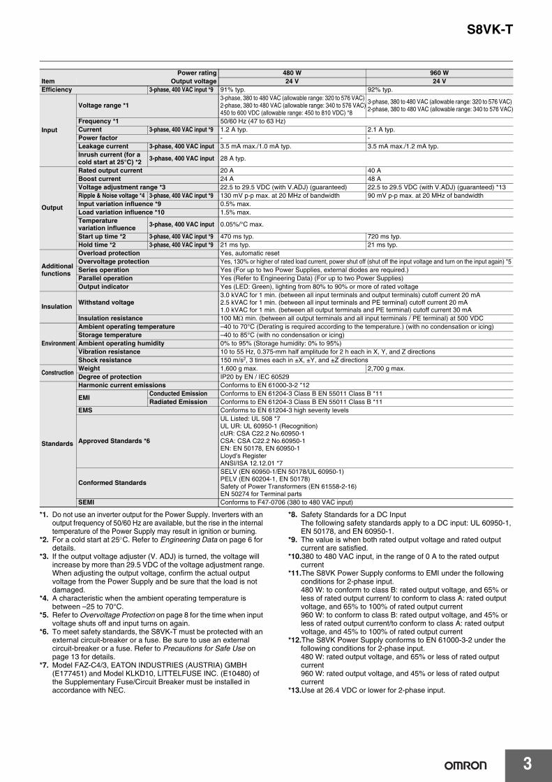
Dimensions (Unit: mm)
112.2
117.8
122.2
(10)
(4)(1)
125
4.7(Sliding: 7.5 max.)
104.6
6.35
40
Rail Stopper
6.35
19.8
S8VK-T12024 (120 W)
140
145.6
150
(10)
(4)(1)
125
4.7(Sliding: 7.5 max.)
104.6
6.35
60
6.35
19.8
Rail Stopper
S8VK-T24024 (240 W)
30 25
(26.8)19.8
140
145.6
150
(10)
(4)
125
4.7(Sliding: 7.5 max.)
95
6.35 6.35
(1)
52.3
Rail Stopper
S8VK-T48024 (480 W)
32.9541.78
10.16 10.16
(36.7)
19.8
135 170
175.6
180
(10)
(4)
125
(1)
47.9
Rail Stopper
4.7(Sliding: 7.5 max.)
S8VK-T96024 (960 W)

S8VK-T
10
DIN Rail (Order Separately)Note: All units are in millimeters unless otherwise indicated.
Mounting Rail (Material: Aluminum)PFP-100N PFP-50N
Mounting Rail (Material: Aluminum)PFP-100N2
End PlatePFP-M
Note: If there is a possibility that the Unit will be subject to vibration or shock, use a steel DIN Rail. Otherwise, metallic filings may result from aluminum abrasion.
4.5
15 25 2510 10
1,000 (500) *
25 25 15(5) *
35±0.3
7.3±0.15
27±0.15
1
* Values in parentheses are for the PFP-50N.
4.5
15 25 2510 10
1,000
25 25 15 1 1.5
29.2242735±0.3
16
1.3
4.8
35.5 35.51.8
1.8
106.2
1
50
11.5
10M4 spring washer
M4×8 pan-head screw

S8VK-T
11
Mounting Brackets
Note: Be sure to use the accessory screws.Mounting screw tightening torque (recommended): 4.43 to 5.31 lb-in (0.5 to 0.6 N·m)
Name Model Qty used
Front-mounting bracket (for 120, 240 and 480 W models) S82Y-VK10F 1
Front-mounting bracket (for 960 W model) S82Y-VK10F 2
Side-mounting bracket (for 120 W model) S82Y-VK10S 1
Side-mounting bracket (for 240 W model) S82Y-VK20S 1
Type Model Dimensions Appearance
Front-mounting bracket (for 120, 240, 480 W and 960 W models)
S82Y-VK10F
Side-mounting bracket (For 120 W model)
S82Y-VK10S
Side-mounting bracket (For 240 W model)
S82Y-VK20S
38
150140±0.1
25±0.1
4-4.5 dia.±0.1
5.464±0.1
t = 2.0
For 960W type
120 W model
960 W model
240 W model
140±0.1
50±0.1 15.5±0.1
150125
73
4-4.5 dia.±0.1
4940
t = 2.0
Left-side mounting Right-side mounting
140±0.1
50±0.1 15.5±0.1
150125
73
5940
4-4.5 dia.±0.1
t = 2.0
Left-side mounting Right-side mounting
S8VK-T
12
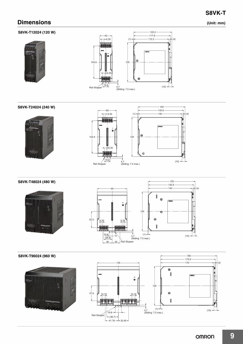
Safety PrecautionsWarning Indications
Meaning of Product Safety Symbols
!CAUTIONMinor electric shock, fire, or Product failure may occasionally occur. Do not disassemble, modify, or repair the Product or touch the interior of the Product.
Minor burns may occasionally occur. Do not touch the Product while power is being supplied or immediately after power is turned OFF.
Fire may occasionally occur. Tighten terminal screws to the specified torque.S8VK-T12024, S8VK-T24024, S8VK-T48024: 4.43 to 5.31 lb-in (0.5 to 0.6 N•m)S8VK-T96024: 10.62 to 13.28 lb-in (1.2 to 1.5 N•m)
Minor injury due to electric shock may occasionally occur. Do not touch the terminals while power is being supplied.
Minor electric shock, fire, or Product failure may occasionally occur. Do not allow any pieces of metal or conductors or any clippings or cuttings resulting from installation work to enter the Product.
If the external breaker or fuse is tripped, the equipment may have been seriously damaged.Do not turn ON the input again.
CAUTION
Indicates a potentially hazardous situation which, if not avoided, may result in minor or moderate injury or in property damage.
Precautions for Safe Use
Supplementary comments on what to do or avoid doing, to use the product safely.
Precautions for Correct Use
Supplementary comments on what to do or avoid doing, to prevent failure to operate, malfunction or undesirable effect on product performance.
Used to warn of the risk of electric shock under specific conditions.
Used to warn of the risk of minor injury caused by high temperatures.
Used for general mandatory action precautions for which there is no specified symbol.
Used to indicate prohibition when there is a risk of minor injury from electrical shock or other source if the product is disassembled.

S8VK-T
13
Wiring Connect the ground completely. A protective earthing terminal
stipulated in safety standards is used. Electric shock or malfunction may occur if the ground is not connected completely.
Minor fire may possibly occur. Ensure that input and output terminals are wired correctly.
Do not apply more than 75-N force to the terminal block when tightening it.
Be sure to remove the sheet covering the Product for machining before power-ON so that it does not interfere with heat dissipation.
To comply with safety standards and to ensure equipment safety, connect the input to the S8VK-T through one of the following Breakers or Fuses.
Recommended power circuit-breakers
Use the following material for the wires to be connected to the S8VK-T to prevent smoking or ignition caused by abnormal loads or phase failure.
Wire the input as shown in the following figures depends on your power distribution system. Do not connect the neutral line in a 3-phase, 4-wire system.
Recommended Wire Type/Cross-sectional Area and Stripping Length
The rated current, wire insertion hole, and applicable screwdriver of the terminal block are as follows.
* When output current exceeds the rated current per terminal, use more than two terminals each for +V and –V.
Installation Environment Do not use the Power Supply in locations subject to shocks or
vibrations. In particular, install the Power Supply as far away as possible from contactors or other devices that are a vibration source. For usage onboard a ship, always attach an End Plate (PFP-M) to both sides of the Power Supply to hold the Power Supply in place.
Install the Power Supply well away from any sources of strong, high-frequency noise and surge.
Operating Life The life of a Power Supply is determined by the life of the
electrolytic capacitors used inside. Here, Arrhenius Law applies,
i.e., the life will be cut in half for each rise of 10C or the life will be doubled for each drop of 10C. The life of the Power Supply can thus be increased by reducing its internal temperature.
Ambient Operating and Storage Environments Store the Power Supply at a temperature of 40 to 85C and a
humidity of 0% to 95%. Do not use the Power Supply in areas outside the derating curve
otherwise, internal parts may occasionally deteriorate or be damaged.
Use the Power Supply at a humidity of 0% to 95%. Do not use the Power Supply in locations subject to direct sunlight. Do not use the Power Supply in locations where liquids, foreign
matter, or corrosive gases may enter the interior of Products.
Precautions for Safe Use
Model Input Recommended power circuit-breakers
S8VK-T12024S8VK-T24024
3-phaseCircuit breaker Conforming UL/CE 480 V, 1 A, characteristic C, 3-pole, or equivalent breaker
2-phase/DC Fuse Conforming UL/CE 600 V, 5 A Fast Acting or identical function fuse
S8VK-T48024S8VK-T96024
3-phaseCircuit breaker Conforming UL/CE 480 V, 4 A, characteristic C, 3-pole, or equivalent breaker
2-phase/DC Fuse Conforming UL/CE 600 V, 10 A Fast Acting or identical function fuse
L1
TN-S
L2L3NPE
L1
TN-C
L2L3
PEN
L1FUSE
2-phase
L2(L3)PE
L1
TT
L2L3N
L1
IT
L2L3
+
DC
-PE
FUSE
ModelINPUT OUTPUT PE
Wire tripping LengthAmerican
Wire GaugeSolid Wire/Stranded Wire
AmericanWire Gauge
Solid Wire/Stranded Wire
AmericanWire Gauge
Solid Wire/Stranded Wire
S8VK-T12024 AWG22 to 10 0.35 to 6 mm2
/0.35 to 4 mm2 AWG18 to 10 0.75 to 6 mm2
/0.75 to 4 mm2
AWG14 to 10 2.5 to 6 mm2 /2.5 to 4 mm2 8 to 10 mmS8VK-T24024 AWG22 to 10 0.35 to 6 mm2
/0.35 to 4 mm2 AWG14 to 10 2.5 to 6 mm2
/2.5 to 4 mm2
S8VK-T48024 AWG20 to 10 0.5 to 6 mm2
/0.5 to 4 mm2 AWG12 to 10 4 to 6 mm2
/4 mm2
S8VK-T96024 AWG16 to 6 1.5 to 16 mm2
/1.5 to 16 mm2 AWG8 to 6 10 to 16 mm2
/10 to 16 mm2 AWG14 to 6 2.5 to 16 mm2 /2.5 to 16 mm2 13 to 16 mm
Model Rated current per terminal *
Wire Insertion Hole (Refer to the diagram on the right) Applicable Screwdriver
W L No. Driver Diameter Length
S8VK-T1202410 A 2.9 2.9 #2 4.9 mm max. 10 mm min.S8VK-T24024
S8VK-T48024S8VK-T96024 30 A 5.4 5 #2 5.1 mm max. 12 mm min. W
L

S8VK-T
14
Mounting Take adequate measures to ensure proper heat dissipation to
increase the long-term reliability of the Product. Be sure to allow convection in the atmosphere around devices when mounting. Do not use in locations where the ambient temperature exceeds the range of the derating curve.
When cutting out holes for mounting, make sure that cuttings do not enter the interior of the Products.
Improper mounting will interfere with heat dissipation and may occasionally result in deterioration or damage of internal parts. Use the Product within the derating curve for the mounting direction that is used.
Overload Protection Internal parts may possibly deteriorate or be damaged if a
short-circuited or overcurrent state continues during operation. Internal parts may possibly deteriorate or be damaged if the Power
Supply is used for applications with frequent inrush current or overloading at the load end. Do not use the Power Supply for such applications.
The DC ON indicator (green) flashes if the overload protection function operates.
Charging a BatteryIf you connect a battery as the load, install overcurrent control and overvoltage protection circuits.
Output Voltage Adjuster (V.ADJ) The output voltage adjuster (V.ADJ) may possibly be damaged if it
is turned with unnecessary force. Do not turn the adjuster with excessive force.
After completing output voltage adjustment, be sure that the output capacity or output current does not exceed the rated output capacity or rated output current.
DIN Rail MountingTo mount the Block on a DIN Rail, hook portion (A) of the Block onto the rail and press the Block in direction (B).
To dismount the Block, pull down portion (C) with a flat-blade screwdriver and pull out the Block.
Series OperationTwo power supplies can be connected in series.
Note: 1. The diode is connected as shown in the figure. If the load is short-circuited, a reverse voltage will be generated inside the Power Supply. If this occurs the Power Supply may possibly deteriorate or be damaged. Always connect a diode as shown in the figure. Select a diode having the following ratings.
2. Although Products having different specifications can be connected in series, the current flowing through the load must not exceed the smaller rated output current.
Making Positive/Negative Outputs The outputs are floating outputs (i.e., the primary circuits and
secondary circuits are separated). You can therefore make positive and negative outputs by using two Power Supplies.You can make positive and negative outputs with any of the models.If positive and negative outputs are used, connect Power Supplies of the same model as in the following figure. (Combinations with different output capacities or output voltages can be made. However, use the lower of the two maximum rated output currents as the current to the loads.)
Depending on the model, internal circuits may be damaged due to startup failure when the power is turned ON if loads such as a servomotor or operational amplifier may operate in series. Therefore, connect bypass diodes (D1, D2) as shown in the following figure.If the list of models that support series connection of outputs says that an external diode is not required, an external diode is also not required for positive/negative outputs.
*1. Convection of air*2. 75 mm min.*3. 75 mm min.*4. 20 mm min.*1 *3
*1 *2
*4
(B)
(A)
(C)
30 mm min.
Rail stopper
Type Schottky Barrier diode
Dielectric strength (VRRM) Twice the rated output voltage or above
Forward current (IF) Twice the rated output current or above
+V
−V
+V
−V
L1
L2
L3
L2
L1
L3
Load
+V
−V
+V
−V
+V
0 V
−V
L1
L2
L3
L2
L1
L3
Load
Load
+V
−V
+V
−V
L1
L2
L3
L2
L1
L3
Load
Load
Load
D2
D1
S8VK-T
15
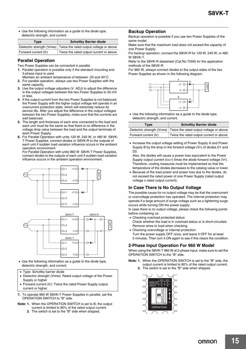
Use the following information as a guide to the diode type, dielectric strength, and current.
Parallel OperationTwo Power Supplies can be connected in parallel.1. Parallel operation is possible only if the standard mounting and
3-phase input is used.Maintain an ambient temperature of between -25 and 40°C.
2. For parallel operation, always use two Power Supplies with the same capacity.
3. Use the output voltage adjusters (V. ADJ) to adjust the difference in the output voltages between the two Power Supplies to 50 mV or less.
4. If the output current from the two Power Supplies is not balanced, the Power Supply with the higher output voltage will operate in an overcurrent protection state, which will extremely reduce its service life. After you adjust the difference in the output voltages between the two Power Supplies, make sure that the currents are well balanced.
5. The length and thickness of each wire connected to the load and each unit must be the same so that there is no difference in the voltage drop value between the load and the output terminals of each Power Supply.
6. For Parallel Operation with units 120 W, 240 W, or 480 W S8VK-T Power Supplies, connect diodes or S8VK-R to the outputs of each unit if sudden load variation influence occurs in the ambient operation environment.For Parallel Operation with units 960 W S8VK-T Power Supplies, connect diodes to the outputs of each unit if sudden load variation influence occurs in the ambient operation environment.
Use the following information as a guide to the diode type, dielectric strength, and current.
7. To operate 960 W S8VK-T Power Supplies in parallel, set the OPERATION SWITCH to "B" side.
Note: 1. When the OPERATION SWITCH is set to B, the output current is limited to 80% of the rated output current.
2. The switch is set to the "B" side when shipped.
Backup OperationBackup operation is possible if you use two Power Supplies of the same model.Make sure that the maximum load does not exceed the capacity of one Power Supply.For backup operation, connect the S8VK-R for 120 W, 240 W, or 480 W S8VK-T.Refer to the S8VK-R datasheet (Cat.No.T059) for the application methods of the S8VK-R.For 960 W, always connect diodes to the output sides of the two Power Supplies as shown in the following diagram.
Use the following information as a guide to the diode type, dielectric strength, and current.
Increase the output voltage setting of Power Supply A and Power Supply B by the drop in the forward voltage (VF) of diodes D1 and D2.Also, the diodes will cause a power loss equivalent to the Power Supply output current (IOUT) times the diode forward voltage (VF). Therefore, cooling measures must be implemented so that the temperature of the diodes decreases to the catalog value or lower.
Because of the load power and power loss due to the diodes, do not exceed the rated power of one Power Supply (rated output voltage x rated output current).
In Case There Is No Output VoltageThe possible cause for no output voltage may be that the overcurrent or overvoltage protection has operated. The internal protection may operate if a large amount of surge voltage such as a lightening surge occurs while turning ON the power supply.In case there is no output voltage, please check the following points before contacting us: Checking overload protected status:
Check whether the load is in overload status or is short-circuited. Remove wires to load when checking.
Checking overvoltage or internal protection: Turn the power supply OFF once, and leave it OFF for at least 5 minutes. Then turn it ON again to see if this clears the condition.
2-Phase Input Operation For 960 W ModelWhen using the S8VK-T 960 W at 2-phase input, make sure to set the OPERATION SWITCH to the "B" side.
Note: 1. When the OPERATION SWITCH is set to the "B" side, the output current is limited to 80% of the rated output current.
2. The switch is set to the "B" side when shipped.
Type Schottky Barrier diode
Dielectric strength (VRRM) Twice the rated output voltage or above
Forward current (IF) Twice the rated output current or above
Type: Schottky barrier diode Dielectric strength (VRRM): Rated output voltage of the Power
Supply or higher Forward current (IF): Twice the rated Power Supply output
current or higher
+V
−V
+V
−V
L1
L2
L3
L2
L1
L3
Load
+V
−V
+V
−V
L1
L2
L3
L2
L1
L3
Load
S8VK-RS8VK-T
S8VK-T
Type Schottky Barrier diode
Dielectric strength (VRRM) Twice the rated output voltage or above
Forward current (IF) Twice the rated output current or above
+V
A
B
D1
D2
−V
+V
−V
L2L1
L3 Load

S8VK-T
16

Read and Understand this Catalog
Please read and understand this catalog before purchasing the product. Please consult your OMRON representative if you have any questions or comments.
Warranty and Limitations of Liability
WARRANTY
OMRON's exclusive warranty is that the products are free from defects in materials and workmanship for a period of one year (or other period if specified) from date of sale by OMRON.
OMRON MAKES NO WARRANTY OR REPRESENTATION, EXPRESS OR IMPLIED, REGARDING NON-INFRINGEMENT, MERCHANTABILITY, OR FITNESS FOR PARTICULAR PURPOSE OF THE PRODUCTS. ANY BUYER OR USER ACKNOWLEDGES THAT THE BUYER OR USER ALONE HAS DETERMINED THAT THE PRODUCTS WILL SUITABLY MEET THE REQUIREMENTS OF THEIR INTENDED USE. OMRON DISCLAIMS ALL OTHER WARRANTIES, EXPRESS OR IMPLIED.
LIMITATIONS OF LIABILITY
OMRON SHALL NOT BE RESPONSIBLE FOR SPECIAL, INDIRECT, OR CONSEQUENTIAL DAMAGES, LOSS OF PROFITS OR COMMERCIAL LOSS IN ANY WAY CONNECTED WITH THE PRODUCTS, WHETHER SUCH CLAIM IS BASED ON CONTRACT, WARRANTY, NEGLIGENCE, OR STRICT LIABILITY.
In no event shall the responsibility of OMRON for any act exceed the individual price of the product on which liability is asserted.
IN NO EVENT SHALL OMRON BE RESPONSIBLE FOR WARRANTY, REPAIR, OR OTHER CLAIMS REGARDING THE PRODUCTS UNLESS OMRON'S ANALYSIS CONFIRMS THAT THE PRODUCTS WERE PROPERLY HANDLED, STORED, INSTALLED, AND MAINTAINED AND NOT SUBJECT TO CONTAMINATION, ABUSE, MISUSE, OR INAPPROPRIATE MODIFICATION OR REPAIR.
Application Considerations
SUITABILITY FOR USE
OMRON shall not be responsible for conformity with any standards, codes, or regulations that apply to the combination of the product in the customer's application or use of the product.
Take all necessary steps to determine the suitability of the product for the systems, machines, and equipment with which it will be used.
Know and observe all prohibitions of use applicable to this product.
NEVER USE THE PRODUCT FOR AN APPLICATION INVOLVING SERIOUS RISK TO LIFE OR PROPERTY WITHOUT ENSURING THAT THE SYSTEM AS A WHOLE HAS BEEN DESIGNED TO ADDRESS THE RISKS, AND THAT THE OMRON PRODUCT IS PROPERLY RATED AND INSTALLED FOR THE INTENDED USE WITHIN THE OVERALL EQUIPMENT OR SYSTEM.
PROGRAMMABLE PRODUCTS
OMRON shall not be responsible for the user's programming of a programmable product, or any consequence thereof.
Disclaimers
CHANGE IN SPECIFICATIONS
Product specifications and accessories may be changed at any time based on improvements and other reasons. Consult with your OMRON representative at any time to confirm actual specifications of purchased product.
DIMENSIONS AND WEIGHTS
Dimensions and weights are nominal and are not to be used for manufacturing purposes, even when tolerances are shown.
PERFORMANCE DATA
Performance data given in this catalog is provided as a guide for the user in determining suitability and does not constitute a warranty. It may represent the result of OMRON's test conditions, and the users must correlate it to actual application requirements. Actual performance is subject to the OMRON Warranty and Limitations of Liability.

Authorized Distributor:
In the interest of product improvement, specifications are subject to change without notice.
Cat. No. T061-E1-01-X 0314 (0314)
© OMRON Corporation 2014 All Rights Reserved.
OMRON Corporation Industrial Automation Company
OMRON ELECTRONICS LLCOne Commerce Drive Schaumburg,IL 60173-5302 U.S.A.Tel: (1) 847-843-7900/Fax: (1) 847-843-7787
Regional HeadquartersOMRON EUROPE B.V.Wegalaan 67-69-2132 JD HoofddorpThe NetherlandsTel: (31)2356-81-300/Fax: (31)2356-81-388
Contact: www.ia.omron.comTokyo, JAPAN
OMRON ASIA PACIFIC PTE. LTD.No. 438A Alexandra Road # 05-05/08 (Lobby 2), Alexandra Technopark, Singapore 119967Tel: (65) 6835-3011/Fax: (65) 6835-2711
OMRON (CHINA) CO., LTD.Room 2211, Bank of China Tower, 200 Yin Cheng Zhong Road, PuDong New Area, Shanghai, 200120, ChinaTel: (86) 21-5037-2222/Fax: (86) 21-5037-2200