Switch Mode Power Supply S8VK-G Datasheet
24
1 New Product Switch Mode Power Supply S8VK-G (15/30/60/120/240/480-W Models) Reliable and Easy Operation-Worldwide Power Supply Resistant in tough environments Easy and fast installation The most compact class on the market • Universal input for worldwide applications: 100 to 240 VAC (85 to 264 VAC) • DC input can be available: 90 to 350 VDC • Possible for 2-phase input usage. • Wide operation temperature range: –40 to 70 °C • Power Boost function at 120% • Safety standards: UL508/60950-1, CSA C22.2 No. 107.1/60950-1 EN50178, EN60950-1. Lloyd’s standards, EN60204-1 PELV Safety of Power Transformers: EN61558-2-16 • ANSI/ISA 12.12.01 (excluding 480-W models) • CSA C22.2 No.213 (excluding 480-W models) • 15-W,30-W, and 60-W models conform to UL Class 2 output Standards • EMS: EN 61204-3 EMI: EN 61204-3 Class B • Three years Warranty *1 *1. Refer to Period and Terms of Warranty on page 22. ! Refer to Safety Precautions for All Power Supplies and Safety Precautions on page 17.
Transcript of Switch Mode Power Supply S8VK-G Datasheet

1
New Product
Switch Mode Power Supply
S8VK-G (15/30/60/120/240/480-W Models)
Reliable and Easy Operation-Worldwide Power SupplyResistant in tough environmentsEasy and fast installationThe most compact class on the market
• Universal input for worldwide applications: 100 to 240 VAC (85 to 264 VAC)
• DC input can be available: 90 to 350 VDC• Possible for 2-phase input usage.• Wide operation temperature range: –40 to 70 °C• Power Boost function at 120%• Safety standards:
UL508/60950-1, CSA C22.2 No. 107.1/60950-1 EN50178, EN60950-1. Lloyd’s standards, EN60204-1 PELV Safety of Power Transformers: EN61558-2-16
• ANSI/ISA 12.12.01 (excluding 480-W models)• CSA C22.2 No.213 (excluding 480-W models)• 15-W,30-W, and 60-W models conform to
UL Class 2 output Standards• EMS: EN 61204-3
EMI: EN 61204-3 Class B• Three years Warranty *1
*1.Refer to Period and Terms of Warranty on page 22.
! Refer to Safety Precautions for All Power Supplies and Safety Precautions on page 17.

S8VK-G
2
Model Number StructureModel Number LegendNote: Not all combinations are possible. Refer to List of Models in Ordering Information, below.
Ordering InformationNote: For details on normal stock models, contact your nearest OMRON representative.
Power ratings Input voltage Output Voltage Output current Boost Current Model number
15 W
Single phase 100 to 240 VAC 90 to 350 VDC
5 V 3 A 3.6 A S8VK-G01505
12 V 1.2 A 1.44 A S8VK-G01512
24 V 0.65 A 0.78 A S8VK-G01524
30 W
5 V 5 A 6 A S8VK-G03005
12 V 2.5 A 3 A S8VK-G03012
24 V 1.3 A 1.56 A S8VK-G03024
60 W12 V 4.5 A 5.4 A S8VK-G06012
24 V 2.5 A 3 A S8VK-G06024
120 W 24 V 5 A 6 A S8VK-G12024
240 W24 V 10 A 12 A S8VK-G24024
48 V 5 A 6 A S8VK-G24048
480 W24 V 20 A 24 A S8VK-G48024
48 V 10 A 12 A S8VK-G48048
1 2 3 4S8VK- @@@@@@-@
1. Input voltage typeG: Single phase
2. Power Ratings015: 15 W030: 30 W060: 60 W120: 120 W240: 240 W480: 480 W
3. Output voltage05: 5 V12: 12 V24: 24 V48: 48 V
4. OptionNone: Standard model400: Coationg

S8VK-G
3
SpecificationsRatings, Characteristics, and Functions
*1. Do not use an inverter output for the Power Supply. Inverters with an output frequency of 50/60 Hz are available, but the rise in the internal temperature of the Power Supply may result in ignition or burning.
*2. For a cold start at 25°C. Refer to Engineering Data on page 9 to 11 for details.*3. If the output voltage adjuster (V. ADJ) is turned, the voltage will increase by more than +15% of the voltage adjustment range. When adjusting the output voltage, confirm
the actual output voltage from the Power Supply and be sure that the load is not damaged. *4. A characteristic when the ambient operating temperature is between –25 to 70°C.*5. Refer to Overvoltage Protection on page 10 for the time when input voltage shuts off and input turns on again.*6. The value is when both rated output voltage and rated output current are satisfied.*7. 100 to 240 VAC input, in the range of 0 A to the rated output current*8. This is the maximum variation in the output voltage when the input voltage is gradually changed within the allowable input voltage range at the rated output voltage and rated output current.*9. Refer to Recommended Replacement Periods and Periodic Replacement for Preventive Maintenance on page 22 for details.*10. Safety Standards for a DC Input
The following safety standards apply to a DC input: UL 60950-1, cUR (CSA C22.2 No. 60950-1), EN 50178, EN 60950-1, and Lloyd’s. For a DC input, safety is ensured by an external fuse. Select an external fuse that meets the following conditions.S8VK-G015@@: 350 VDC min, 3 AS8VK-G030@@: 350 VDC min, 4 A
*11. Clamp filter “ZCAT2035-0930” manufactured by TDK Corporation. or equivalent should be installed in the cable connected to the input - output terminals of S8VK-G series. Noise filter “FN2080-10-06” manufactured by SCHAFFNER Corporation. or equivalent should be connected to the Input terminals of S8VK-G series.
*12. At −40 to −25°C, time will be required before the rated output voltage is output after the input voltage is input.Also, the ripple noise value may exceed the value shown in the above table.
Power rating 15 W 30 WItem Output voltage 5 V 12 V 24 V 5 V 12 V 24 VEfficiency 230 VAC input *6 77% typ. 77% typ. 80% typ. 79% typ. 82% typ. 86% typ.
Input
Voltage range *1 Single-phase, 85 to 264 VAC, 90 to 350 VDC *10Frequency *1 50/60 Hz (47 to 450 Hz)
Current 115 VAC input *6 0.32 A typ. 0.3 A typ. 0.31 A typ. 0.5 A typ. 0.57 A typ. 0.58 A typ.230 VAC input *6 0.2 A typ. 0.21 A typ. 0.2 A typ. 0.32 A typ. 0.37 A typ. 0.36 A typ.
Power factor 230 VAC input, 100% load 0.42 min. 0.43 min. 0.42 min. 0.43 min.
Leakage current 115 VAC input 0.14 mA typ. 0.13 mA typ.230 VAC input 0.25 mA typ. 0.24 mA typ.
Inrush current *2 (for a cold start at 25°C)
115 VAC input 16 A typ 16 A typ230 VAC input 32 A typ. 32 A typ.
Output
Rated output current 3 A 1.2 A 0.65 A 5 A 2.5 A 1.3 ABoost current 3.6 A 1.44 A 0.78 A 6 A 3 A 1.56 AVoltage adjustment range *3 –10% to 15% (with V.ADJ) (guaranteed)Ripple & Noise voltage *4
100 to 240 VAC input, 100% load *6
60 mVp-p max. at 20 MHz of bandwidth
50 mVp-p max.at 20 MHz of bandwidth
30 mVp-p max. at 20 MHz of bandwidth
30 mVp-p max. at 20 MHz of bandwidth
30 mVp-p max. at 20 MHz of bandwidth
30 mVp-p max. at 20 MHz of bandwidth
Input variation influence *8 0.4% max. 0.4% max.Load variation influence *7 0.8% max. 0.8% max.Temperature variation influence 115 to 230 VAC input 0.05%/°C max. 0.05%/°C max.
Start up time *2115 VAC input *6 530 ms typ. 520 ms typ. 580 ms typ. 550 ms typ. 550 ms typ. 600 ms typ.230 VAC input *6 330 ms typ. 400 ms typ. 400 ms typ. 430 ms typ. 490 ms typ. 480 ms typ.
Hold time *2115 VAC input *6 28 ms typ. 29 ms typ. 32 ms typ. 33 ms typ. 36 ms typ. 23 ms typ.230 VAC input *6 134 ms typ. 138 ms typ. 134 ms typ. 177 ms typ. 170 ms typ. 154 ms typ.
Additional functions
Overload protection Yes, automatic reset Yes, automatic resetOvervoltage protection *5 Yes, 130% or higher of rated output voltage, power shut off (shut off the input voltage and turn on the input again) Series operation Yes (For up to two Power Supplies, external diodes are required.)Parallel operation Yes (Refer to Safety Precautions) (For up to two Power Supplies)Output indicator Yes (LED: Green), lighting from 80% to 90% or more of rated voltage
InsulationWithstand voltage
3.0 kVAC for 1 min. (between all input terminals and output terminals), current cutoff 20 mA2.0 kVAC for 1 min. (between all input terminals and PE terminals), current cutoff 20 mA1.0 kVAC for 1 min. (between all output terminals and PE terminals), current cutoff 20 mA
Insulation resistance 100 MΩ min. (between all output terminals and all input terminals/PE terminals) at 500 VDC
Environment
Ambient operating temperature *12 –40 to 70°C (Derating is required according to the temperature. Refer to Engineering Data) (with no condensation or icing)Storage temperature –40 to 85°C (with no condensation or icing)Ambient operating humidity 0% to 95% (Storage humidity: 0% to 95%)Vibration resistance 10 to 55 Hz, 0.375 mm half amplitude for 2 h each in X, Y, and Z directionsShock resistance 150 m/s2, 3 times each in ±X, ±Y, and ±Z directions
ReliabilityMTBF 135,000 hrs min.Life expectancy *9 10 years min.
ConstructionWeight 150 g max. 195 g max.Cooling fan NoDegree of protection IP20 by EN/IEC 60529
Standards
Harmonic current emissions Conforms to EN 61000-3-2
EMIConducted Emissions Conforms to EN 61204-3 Class B, EN 55011 Class BRadiated Emissions Conforms to EN 61204-3 Class B, EN 55011 Class B
EMS Conforms to EN 61204-3 high severity levels
Approved Standards
UL Listed: UL 508 (Listing, Class2 Output: Per UL 1310)UL UR: UL 60950-1 (Recognition)cUL: CSA C22.2 No.107.1 (Class2 Output: Per CSA C22.2 No.223)cUR:CSA C22.2 No.60950-1EN/VDE: EN 50178, EN 60950-1ANSI/ISA 12.12.01
Conformed StandardsPELV (EN 60204-1, EN 50178)EN 61558-2-16
Marine Standards Lloyd’s register *10 *11SEMI Conforms to F47-0706 ( 200 to 240 VAC input)

S8VK-G
4
*1. Do not use an inverter output for the Power Supply. Inverters with an output frequency of 50/60 Hz are available, but the rise in the internal temperature of the Power Supply may result in ignition or burning.
*2. For a cold start at 25°C. Refer to Engineering Data on page 9 to 11 for details.*3. If the output voltage adjuster (V. ADJ) is turned, the voltage will increase by more than +15% of the voltage adjustment range. When adjusting the output voltage, confirm
the actual output voltage from the Power Supply and be sure that the load is not damaged. *4. A characteristic when the ambient operating temperature is between –25 to 70°C.*5. Refer to Overvoltage Protection on page 10 for the time when input voltage shuts off and input turns on again.*6. The value is when both rated output voltage and rated output current are satisfied.*7. 100 to 240 VAC input, in the range of 0 A to the rated output current*8. This is the maximum variation in the output voltage when the input voltage is gradually changed within the allowable input voltage range at the rated output voltage and rated output current.*9. Refer to Recommended Replacement Periods and Periodic Replacement for Preventive Maintenance on page 22 for details.*10. Safety Standards for a DC Input
The following safety standards apply to a DC input: UL 60950-1, cUR (CSA C22.2 No. 60950-1), EN 50178, EN 60950-1, and Lloyd’s. For a DC input, safety is ensured by an external fuse. Select an external fuse that meets the following conditions.S8VK-G060@@: 350 VDC min, 6 AS8VK-G12024: 350 VDC min, 5 A
*11. Clamp filter “ZCAT2035-0930” manufactured by TDK Corporation. or equivalent should be installed in the cable connected to the input - output terminals of S8VK-G series. Noise filter “FN2080-10-06” manufactured by SCHAFFNER Corporation. or equivalent should be connected to the Input terminals of S8VK-G series.
*12. At −40 to −25°C, time will be required before the rated output voltage is output after the input voltage is input.Also, the ripple noise value may exceed the value shown in the above table.
Power rating 60 W 120 WItem Output voltage 12 V 24 V 24 VEfficiency 230 VAC input *6 85% typ. 88% typ. 89% typ.
Input
Voltage range *1 Single-phase, 85 to 264 VAC, 90 to 350 VDC *10
Frequency *1 50/60 Hz (47 to 450 Hz) 50/60 Hz (47 to 63 Hz)
Current 115 VAC input *6 1.0 A typ. 1.1 A typ. 1.3 A typ. 230 VAC input *6 0.6 A typ. 0.7 A typ. 0.7 A typ.
Power factor 230 VAC input, 100% load 0.46 min. 0.45 min. 0.94 min.
Leakage current 115 VAC input 0.16 mA typ. 0.24 mA typ.230 VAC input 0.30 mA typ. 0.38 mA typ.
Inrush current *2 (for a cold start at 25°C)
115 VAC input 16 A typ. 16 A typ. 230 VAC input 32 A typ. 32 A typ.
Output
Rated output current 4.5 A 2.5 A 5 A Boost current 5.4 A 3 A 6 A Voltage adjustment range *3 −10% to 15% (with V. ADJ) (guaranteed)Ripple & Noise voltage *4
100 to 240 VAC input, 100% load *6
150 mVp-p max. at 20 MHz of bandwidth
50 mVp-p max. at 20 MHz of bandwidth
150 mVp-p max. at 20 MHz of bandwidth
Input variation influence *8 0.4% max. 0.4% max.Load variation influence *7 0.8% max. 0.8% max.Temperature variation influence 115 to 230 VAC input 0.05%/°C max. 0.05%/°C max.
Start up time *2115 VAC input *6 570 ms typ. 650 ms typ. 790 ms typ. 230 VAC input *6 430 ms typ. 500 ms typ. 750 ms typ.
Hold time *2115 VAC input *6 26 ms typ. 25 ms typ. 42 ms typ. 230 VAC input *6 139 ms typ. 129 ms typ. 42 ms typ.
Additional functions
Overload protection Yes, automatic reset Yes, automatic resetOvervoltage protection *5 Yes, 130% or higher of rated output voltage, power shut off (shut off the input voltage and turn on the input again) Series operation Yes (For up to two Power Supplies, external diodes are required.)Parallel operation Yes (Refer to Safety Precautions) (For up to two Power Supplies)Output indicator Yes (LED: Green), lighting from 80% to 90% or more of rated voltage
InsulationWithstand voltage
3.0 kVAC for 1 min. (between all input terminals and output terminals), current cutoff 20 mA2.0 kVAC for 1 min. (between all input terminals and PE terminals), current cutoff 20 mA1.0 kVAC for 1 min. (between all output terminals and PE terminals), current cutoff 20 mA
Insulation resistance 100 MΩ min. (between all output terminals and all input terminals/PE terminals) at 500 VDC
Environment
Ambient operating temperature *12 −40 to 70°C (Derating is required according to the temperature. Refer to Engineering Data) (with no condensation or icing)Storage temperature −40 to 85°C (with no condensation or icing)Ambient operating humidity 0% to 95% (Storage humidity: 0% to 95%)Vibration resistance 10 to 55 Hz, 0.375 mm half amplitude for 2 h each in X, Y, and Z directionsShock resistance 150 m/s2, 3 times each in ±X, ±Y, ±Z directions
ReliabilityMTBF 135,000 hrs min.Life expectancy *9 10 years min.
ConstructionWeight 260 g max. 620 g max.Cooling fan NoDegree of protection IP20 by EN/IEC 60529
Standards
Harmonic current emissions Conforms to EN 61000-3-2
EMIConducted Emissions Conforms to EN 61204-3 Class B, EN 55011 Class BRadiated Emissions Conforms to EN 61204-3 Class B, EN 55011 Class B
EMS Conforms to EN 61204-3 high severity levels
Approved Standards
UL Listed: UL 508 (Listing, For 60 W only Class2 Output: Per UL 1310 )UL UR: UL 60950-1 (Recognition)cUL: CSA C22.2 No.107.1 (For 60 W only Class2 Output: Per CSA C22.2 No.223)cUR: CSA C22.2 No.60950-1EN/VDE: EN 50178, EN 60950-1ANSI/ISA 12.12.01
Conformed StandardsPELV (EN 60204-1, EN 50178)EN 61558-2-16
Marine Standards Lloyd’s register *10 *11SEMI Conforms to F47-0706 (200 to 240 VAC input)

S8VK-G
5
*1. Do not use an inverter output for the Power Supply. Inverters with an output frequency of 50/60 Hz are available, but the rise in the internal temperature of the Power Supply may result in ignition or burning.*2. For a cold start at 25°C. Refer to Engineering Data on page 9 to 11 for details.*3. If the output voltage adjuster (V. ADJ) is turned, the voltage will increase by more than +15% of the voltage adjustment range. When adjusting the output voltage, confirm
the actual output voltage from the Power Supply and be sure that the load is not damaged. *4. A characteristic when the ambient operating temperature is between –25 to 70°C.*5. Refer to Overvoltage Protection on page 10 for the time when input voltage shuts off and input turns on again.*6. The value is when both rated output voltage and rated output current are satisfied.*7. 100 to 240 VAC input, in the range of 0 A to the rated output current*8. This is the maximum variation in the output voltage when the input voltage is gradually changed within the allowable input voltage range at the rated output voltage and rated output current.*9. Refer to Recommended Replacement Periods and Periodic Replacement for Preventive Maintenance on page 22 for details.*10. Safety Standards for a DC Input
The following safety standards apply to a DC input: UL 60950-1, cUR (CSA C22.2 No. 60950-1), EN 50178, EN 60950-1, and Lloyd’s. For a DC input, safety is ensured by an external fuse. Select an external fuse that meets the following conditions.S8VK-G240@@: 350 VDC min, 8 AS8VK-G480@@: 350 VDC min, 12 A
*11. Clamp filter “ZCAT2035-0930” manufactured by TDK Corporation. or equivalent should be installed in the cable connected to the input - output terminals of S8VK-G series. Noise filter “FN2080-10-06” manufactured by SCHAFFNER Corporation. or equivalent should be connected to the Input terminals of S8VK-G series.
*12. At −40 to −25°C, time will be required before the rated output voltage is output after the input voltage is input.Also, the ripple noise value may exceed the value shown in the above table.
Power rating 240 W 480 WItem Output voltage 24 V 48 V 24 V 48 VEfficiency 230 VAC input *6 92% typ. 93% typ.
Input
Voltage range *1 Single-phase, 85 to 264 VAC, 90 to 350 VDC *10 Frequency *1 50/60 Hz (47 to 63 Hz)
Current 115 VAC input *6 2.4 A typ. 4.7 A typ. 230 VAC input *6 1.3 A typ. 2.3 A typ.
Power factor 230 VAC input, 100% load 0.9 min. 0.97 min.
Leakage current 115 VAC input 0.23 mA typ. 0.3 mA typ.230 VAC input 0.33 mA typ. 0.49 mA typ.
Inrush current *2 (for a cold start at 25°C)
115 VAC input 16 A typ. 16 A typ. 230 VAC input 32 A typ. 32 A typ.
Output
Rated output current 10 A 5 A 20 A 10 A Boost current 12 A 6 A 24 A 12 A Voltage adjustment range *3 −10% to 15% (with V.ADJ) (guaranteed)Ripple & Noise voltage *4
100 to 240 VAC input, 100% load *6
180 mVp-p max. at 20 MHz of bandwidth
350 mVp-p max. at 20 MHz of bandwidth
230 mVp-p max. at 20 MHz of bandwidth
470 mVp-p max. at 20 MHz of bandwidth
Input variation influence *8 0.4% max. 0.4% max.Load variation influence *7 0.8% max. 0.8% max.Temperature variation influence 115 to 230 VAC input 0.05%/°C max. 0.05%/°C max.
Start up time *2115 VAC input *6 250 ms typ. 290 ms typ. 380 ms typ. 230 VAC input *6 250 ms typ. 290 ms typ. 260 ms typ.
Hold time *2115 VAC input *6 44 ms typ. 43 ms typ. 40 ms typ. 230 VAC input *6 44 ms typ. 50 ms typ.
Additional functions
Overload protection Yes, automatic reset Yes, automatic resetOvervoltage protection *5 Yes, 130% or higher of rated output voltage, power shut off (shut off the input voltage and turn on the input again)Series operation Yes (For up to two Power Supplies, external diodes are required.)Parallel operation Yes (Refer to Safety Precautions) (For up to two Power Supplies)Output indicator Yes (LED: Green), lighting from 80% to 90% or more of rated voltage
InsulationWithstand voltage
3.0 kVAC for 1 min. (between all input terminals and output terminals), current cutoff 20 mA2.0 kVAC for 1 min. (between all input terminals and PE terminals), current cutoff 20 mA1.0 kVAC for 1 min. (between all output terminals and PE terminals), current cutoff 20 mA
Insulation resistance 100 MΩ min. (between all output terminals and all input terminals/PE terminals) at 500 VDC
Environment
Ambient operating temperature *12 −40 to 70 °C (Derating is required according to the temperature. Refer to Engineering Data) (with no condensation or icing)Storage temperature −40 to 85°C (with no condensation or icing)Ambient operating humidity 0% to 95% (Storage humidity: 0% to 95%)Vibration resistance 10 to 55 Hz, 0.375 mm half amplitude for 2 h each in X, Y, and Z directionsShock resistance 150 m/s2, 3 times each in ±X, ±Y, ±Z directions
ReliabilityMTBF 135,000 hrs min.Life expectancy *9 10 years min.
Construction
Weight 900 g max. 1,500 g max.Cooling fan NoDegree of protection IP20 by EN/IEC 60529
Standards
Harmonic current emissions Conforms to EN 61000-3-2
EMIConducted Emissions Conforms to EN 61204-3 Class B, EN 55011 Class BRadiated Emissions Conforms to EN 61204-3 Class B, EN 55011 Class B
EMS Conforms to EN 61204-3 high severity levels
Approved Standards
UL Listed: UL 508 (Listing)UL UR: UL 60950-1 (Recognition)cUL: CSA C22.2 No.107.1cUR: CSA C22.2 No.60950-1EN/VDE: EN 50178, EN 60950-1ANSI/ISA 12.12.01
Conformed StandardsPELV (EN 60204-1, EN 50178)EN 61558-2-16
Marine Standards Lloyd’s register *10 *11
SEMI Conforms to F47-0706 (200 to 240 VAC input)

S8VK-G
6
ConnectionsBlock Diagrams
Voltage detection circuit
Photocoupler
Rectifier/smoothing
circuit
AC (L)
INPUT
AC (N)
Drive control circuit
+V
+V
−V
−V
DC OUTPUT
Fuse:250 VAC 3.15 A HBC
Overvoltage detection circuit
Noise filter
Inrush current
protection
Rectifier Smoothing circuit
Overcurrent detection circuit
S8VK-G015@@ (15 W)
Voltage detection circuit
Overcurrentcircuit
Current detection circuit
Photocoupler
Rectifier/smoothing
circuit
AC (L)
INPUT
AC (N)
Drive control circuit
Fuse:250 VAC 4.0 A HBC
Overvoltage detection circuit
Noise filter
Inrush current
protectionRectifier Smoothing
circuit
Overcurrent detection circuit
+V
+V
−V
−V
−V
DC OUTPUT
S8VK-G030@@ (30 W)
Voltage detection circuit
Photocoupler
Rectifier/smoothing
circuit
AC (L)
INPUT
AC (N)
Drive control circuit
Fuse:250 VAC 6.3 A HBC
Overvoltage detection circuit
Noise filter
Inrush current
protectionRectifier Smoothing
circuit
Overcurrent detection circuit
+V
+V
−V
−V
−V
DC OUTPUT
Overcurrentcircuit
Current detection circuit
S8VK-G060@@ (60 W)

S8VK-G
7
Photocoupler
Noise filter
AC (L)
INPUT
AC (N)
Fuse:250 VAC 5.0 A HBC
Rectifier Inrush current protection circuit
Smoothing circuit
Harmonic current suppression circuit (Power factor improvement)
Drive control circuit
Rectifier/smoothing circuit
Voltage detection circuit
Overvoltage detection circuit
+V
+V
−V
−V
−V
DC OUTPUT
Overcurrent detection circuit
S8VK-G12024 (120 W)
Photocoupler
Noise filter
AC (L)
INPUT
AC (N)
Fuse:250 VAC 8.0 A HBC
Rectifier Inrush current protection
Smoothing circuit
Harmonic current suppression circuit (Power factor improvement)
Drive control circuit
Rectifier/smoothing circuit
Voltage detection circuit
Overvoltage detection circuit
+V
+V
−V
−V
−V
DC OUTPUT
Overcurrentcircuit
Current detection circuit
Overcurrent detection circuit
S8VK-G240@@ (240 W)
Photocoupler
Noise filter
AC (L)
INPUT
AC (N)
Fuse:250 VAC 12.0 A HBC
RectifierInrush current protection circuit
Smoothing circuit
Harmonic current suppression circuit (Power factor improvement)
Drive control circuit
Rectifier/smoothing circuit
Voltage detection circuit
Overvoltage detection circuit
+V
+V
−V
−V
−V
DC OUTPUT
Overcurrentcircuit
Current detection circuit
Overcurrent detection circuit
S8VK-G480@@ (480 W)

S8VK-G
8
Construction and NomenclatureNomenclature
*1. The fuse is located on the (L) side. It is not user-replaceable. For a DC input, connect the positive voltage to the L terminal.*2. This is the protective earth terminal specified in the safety standards. Always ground this terminal.
15-W Models 30-W Models 60-W ModelsS8VK-G015@@ S8VK-G030@@ S8VK-G060@@
120-W Models 240-W Models 480-W ModelsS8VK-G12024 S8VK-G240@@ S8VK-G480@@
No. Name Function1 Input terminals (L), (N) Connect the input lines to these terminals. *12 Protective Earth terminal (PE) Connect the ground line to this terminal. *23 DC Output terminals (−V), (+V) Connect the load lines to these terminals.4 Output indicator (DC ON: Green) Lights while a direct current (DC) output is ON.5 Output voltage adjuster (V.ADJ) Use to adjust the voltage.
3
1 2
4
5
3
1 2
5
4
3
1 2
5
4
1 2
3
5
4
1 2
5
4
3
1 2 3
5
4

S8VK-G
9
Engineering DataDerating Curve15, 30, 240 W (S8VK-G015@@, S8VK-G030@@, S8VK-G240@@)
Note: 1. At less than 90 VAC, the derating is 2.5%/V2. For a DC power input, reduce the load given in the above
derating curve by multiplying the following coefficients.S8VK-G015@@: 1.0S8VK-G030@@: 0.9S8VK-G240@@: 0.8
3. This is the guaranteed value for startup.
A. Standard mountingB. Face-up mounting / Side mounting (15W only)
60 W (S8VK-G060@@)
Note: 1. At less than 90 VAC, the derating is 2.5%/V2. For a DC power input, reduce the load given in the above
derating curve by multiplying the following coefficients.S8VK-G060@@: 0.9
3. This is the guaranteed value for startup.
A. Standard mountingB. Face-up mounting
120 W (S8VK-G12024)
Note: 1. At less than 90 VAC, the derating is 2.5%/V2. For a DC power input, reduce the load given in the above
derating curve by multiplying the following coefficients.S8VK-G12024: 0.9
3. This is the guaranteed value for startup.
A. Standard mountingB. Face-up mounting
480 W (S8VK-G480@@)
Note: 1. At less than 90 VAC, the derating is 2.5%/V2. For a DC power input, reduce the load given in the above
derating curve by multiplying the following coefficients.S8VK-G480@@: 0.8
3. This is the guaranteed value for startup.
A. Standard mountingB. Face-up mounting
−40 −25 −10 0 10 20
A
B
30 40 50 60 70 80
120
100
80
60
40
20
0
Load
rat
io (
%)
Ambient temperature (°C)
−40 −25 −10 0 10 20
A
B
30 40 50 60 70 80
120
100
80
60
40
20
0
Load
rat
io (
%)
Ambient temperature (°C)
−40 −25 −10 0 10 20
A
30 40 50 60 70 80
120
100
80
60
40
20
0
B
Load
rat
io (
%)
Ambient temperature (°C)
−40 −25 −10 0 10 20
A
B
30 40 50 60 70 80
120
100
80
60
40
20
0
Load
rat
io (
%)
Ambient temperature (°C)

S8VK-G
10
Mounting
Side mounting is only for S8VK-G015@@. Use a mounting bracket (S82Y-VK15P, sold separately) when the product is mounted horizontally. Heat dissipation will be adversely affected. When the product is mounted facing horizontally, always place the side with label facing upward.
Overload ProtectionThe load and the power supply are automatically protected from overcurrent damage by this function.Overload protection is activated if the output current rises above 121% of the rated current.When the output current returns within the rated range, overload protection is automatically cleared.
Note: 1. Internal parts may occasionally deteriorate or be damaged if a short-circuited or overcurrent state continues during operation.
2. Internal parts may possibly deteriorate or be damaged if the Power Supply is used for applications with frequent inrush current or overloading at the load end. Do not use the Power Supply for such applications.
Overvoltage ProtectionConsider the possibility of an overvoltage and design the system so that the load will not be subjected to an excessive voltage even if the feedback circuit in the Power Supply fails. If an excessive voltage that is approximately 130% of the rated voltage or more is output, the output voltage is shut OFF. Reset the input power by turning it OFF for at least three minutes and then turning it back ON again.
Note: Do not turn ON the power again until the cause of the overvoltage has been removed.
Inrush Current, Startup Time, Output Hold Time
Note: Twice the input current or above will flow during the parallel operation or redundant system.Therefore, check the fusing characteristics of fuses and operating characteristics of breakers making sure that the external fuses will not burn out and the circuit breakers will not be activated by the inrush current.
(B) Face-up mounting(A) Standard (Vertical) mounting
(C) Side mounting only for 15 W
Side with label
S82Y-VK15P
The values shown in the above diagrams are for reference only.
0 50 100
Output current (%)
Out
put v
olta
ge (
V)
Intermittent operation
+15%
−10%
0 V
+30%(approx.)
Overvoltage protection operating
Variable rangeRated output voltage
Out
put v
olta
ge (
V)
The values shown in the above diagram is for reference only.
90% 96.5%
Startup time
AC inputvoltage
AC inputcurrent
Outputvoltage
Inrush current on input application
Input OFFInput ON
Hold time

S8VK-G
11
Two phases application for Single phase modelsFor All Single phase Models, S8VK-GBasically OMRON single phase power supply can be used on two-phases of a 3–phase-system when some of conditions satisfy like below.
1. The supplying voltage is below the maximum rated input.OMRON Power supply allows the input voltage equivalent or less than 240 VAC+10%. Please confirm the input voltage between two lines if the input voltage satisfies this condition before connecting.
2. The external protector is needed on N input line to secure a safety. N line has no protection of a fuse internally. An appropriate fuse or circuit breaker should be connected on N input line like the following.
Reference Value
Reliability (MTBF)
Value
Single phase model15 W: 600,000 hrs30 W: 580,000 hrs60 W: 590,000 hrs120 W: 450,000 hrs240 W: 360,000 hrs480 W: 230,000 hrs
Definition
MTBF stands for Mean Time Between Failures, which is calculated according to the probability of accidental device failures, and indicates reliability of devices.Therefore, it does not necessarily represent a life of the product.
Life expectancy 10 yrs. Min.
Definition
The life expectancy indicates average operating hours under the ambient temperature of 40°C and a load rate of 50%. Normally this is determined by the life expectancy of the built-in aluminum electrolytic capacitor.
An external fuse or a circuit breaker
max. 240 VAC+10%
Internal Fuse
Power Supply
NL
L1 L2 L3 PE
S8VK-G
12
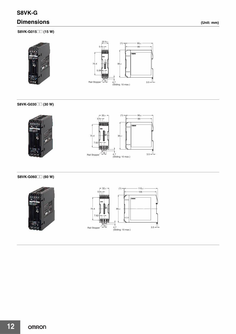
Dimensions (Unit: mm)
5
(1)
3.5
5.08
16
22.5±1
Rail Stopper
86
75.4 90±1
4.7(Sliding: 10 max.)
90±1
S8VK-G015@@ (15 W)
5
(1)
3.5
7.62
16
32±1
Rail Stopper
86
75.4 90±1
4.7(Sliding: 10 max.)
90±1
S8VK-G030@@ (30 W)
110±1
1065
7.62
16
32±1
Rail Stopper
75.4
4.7(Sliding: 10 max.)
(1)
3.5
90±1
S8VK-G060@@ (60 W)

S8VK-G
13
117.8
122.2±1(1)
(10)
112.2 (4)
6.35
6.35
40±1
104.6 125±1
19.8Rail Stopper 4.7
(Sliding: 7.5 max.)
S8VK-G12024 (120 W)
(1)
140
145.6
(10)
(4)6.35
6.35
19.8Rail Stopper
150±1
4.7(Sliding: 7.5max.)
104.6
60±1
125±1
S8VK-G240@@ (240 W)
(10)
(4)140
145.6
(1)
6.35 6.35
30 25
19.8
Rail Stopper
52.3
95±1
150±1
125±1
4.7(Sliding: 7.5 max.)
S8VK-G480@@ (480 W)

S8VK-G
14
DIN Rail (Order Separately)Note: All units are in millimeters unless otherwise indicated.
Mounting Rail (Material: Aluminum)PFP-100N PFP-50N
Mounting Rail (Material: Aluminum)PFP-100N2
End PlatePFP-M
Note: If there is a possibility that the Unit will be subject to vibration or shock, use a steel DIN Rail. Otherwise, metallic filings may result from aluminum abrasion.
4.5
15 25 2510 10
1,000 (500) *25 25 15(5) *
35±0.3
7.3±0.15
27±0.15
1
* Values in parentheses are for the PFP-50N.
4.5
15 25 2510 10
1,000
25 25 15 1 1.5
29.2242735±0.3
16
1.3
4.8
35.5 35.51.8
1.8
106.2
1
50
11.5
10M4 spring washer
M4×8 pan-head screw

S8VK-G
15
Mounting Brackets
Note: Be sure to use the accessory screws.Mounting screw tightening torque (recommended): 4.43 to 5.31 lb-in (0.5 to 0.6 N·m)
Name Model
Front-mounting bracket (for 15, 30 and 60 W models) S82Y-VS10F
Front-mounting bracket (for 120, 240 and 480 W models) S82Y-VK10F
Side-mounting bracket (for 15 W models) S82Y-VK15P
Side-mounting bracket (for 30 and 60 W models) S82Y-VS10S
Side-mounting bracket (for 120 W models) S82Y-VK10S
Side-mounting bracket (for 240 W models) S82Y-VK20S
Type Model Dimensions Appearance
Front-mounting bracket (For 15, 30 and 60 W models)
S82Y-VS10F
Front-mounting bracket (For 120, 240 and 480 W models)
S82Y-VK10F
Side-mounting bracket (For 15 W Models)
S82Y-VK15P
41
35±0.1
4050
4.5 dia.±0.1
35 25
107.3
t = 1.0
25±0.1
140±0.1
150
38
4.5 dia.±0.1 5.4
t = 2.0
(For 120 W types) (For 240 W types)
3.5
15
7.10.5 102.2±0.1
12.5±0.1
86.415 15
28
3.5 dia.±0.1
90.4
22.5
t = 0.8
Right-side mounting

S8VK-G
16
* You can mount the side of the Power Supply to a DIN Rail by removing the DIN Rail Back-mounting Bracket and then attaching a Side-mounting Bracket to the Power Supply.
Type Model Dimensions Appearance
Side-mounting bracket(For 30 and 60 W models)
S82Y-VS10S
Side-mounting bracket (For 120 W models)
S82Y-VK10S
Side-mounting bracket (For 240 W models)
S82Y-VK20S
3564
t = 2.0
80 60±0.1
55±0.1 13
4.5 dia.±0.1Left-side mounting Right-side mounting
140±0.1
50±0.1 15.5±0.1
150125
73
4.5 dia.±0.1
4940
t = 2.0
Left-side mounting Right-side mounting
Left-side mounting(DIN Rail) *
Right-side mounting(DIN Rail) *
140±0.1
50±0.1 15.5±0.1
150125
73
5940
4.5 dia.±0.1
t = 2.0
Left-side mounting Right-side mounting
Left-side mounting(DIN Rail) *
Right-side mounting(DIN Rail) *

S8VK-G
17
Safety PrecautionsWarning Indications
Meaning of Product Safety Symbols
!CAUTIONMinor electric shock, fire, or Product failure may occasionally occur. Do not disassemble, modify, or repair the Product or touch the interior of the Product.
Minor burns may occasionally occur. Do not touch the Product while power is being supplied or immediately after power is turned OFF.
Fire may occasionally occur. Tighten terminal screws to the specified torque (0.5 to 0.6 N·m).
Minor injury due to electric shock may occasionally occur. Do not touch the terminals while power is being supplied. Always close the terminal cover after wiring.
Minor electric shock, fire, or Product failure may occasionally occur. Do not allow any pieces of metal or conductors or any clippings or cuttings resulting from installation work to enter the Product.
CAUTION
Indicates a potentially hazardous situation which, if not avoided, may result in minor or moderate injury or in property damage.
Precautions for Safe Use
Supplementary comments on what to do or avoid doing, to use the product safely.
Precautions for Correct Use
Supplementary comments on what to do or avoid doing, to prevent failure to operate, malfunction or undesirable effect on product performance.
Used to warn of the risk of electric shock under specific conditions.
Used to warn of the risk of minor injury caused by high temperatures.
Used for general mandatory action precautions for which there is no specified symbol.
Use to indicate prohibition when there is a risk of minor injury from electrical shock or other source if the product is disassembled.
S8VK-G
18
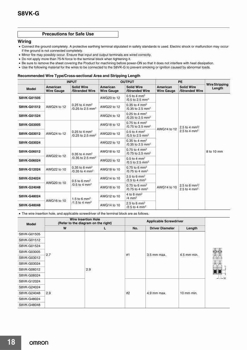
Wiring• Connect the ground completely. A protective earthing terminal stipulated in safety standards is used. Electric shock or malfunction may occur
if the ground is not connected completely.• Minor fire may possibly occur. Ensure that input and output terminals are wired correctly.• Do not apply more than 75-N force to the terminal block when tightening it.• Be sure to remove the sheet covering the Product for machining before power-ON so that it does not interfere with heat dissipation. • Use the following material for the wires to be connected to the S8VK-G to prevent smoking or ignition caused by abnormal loads.
Recommended Wire Type/Cross-sectional Area and Stripping Length
• The wire insertion hole, and applicable screwdriver of the terminal block are as follows.
Precautions for Safe Use
INPUT OUTPUT PEWire Stripping
LengthModel AmericanWire Gauge
Solid Wire/Stranded Wire
AmericanWire Gauge
Solid Wire/Stranded Wire
AmericanWire Gauge
Solid Wire/Stranded Wire
S8VK-G01505
AWG24 to 12 0.25 to 4 mm2
/0.25 to 2.5 mm2
AWG20 to 12 0.5 to 4 mm2
/0.5 to 2.5 mm2
AWG14 to 12 2.5 to 4 mm2/2.5 to 4 mm2
8 to 10 mm
S8VK-G01512 AWG22 to 12 0.35 to 4 mm2
/0.35 to 2.5 mm2
S8VK-G01524 AWG24 to 12 0.25 to 4 mm2
/0.25 to 2.5 mm2
S8VK-G03005
AWG24 to 12 0.25 to 4 mm2
/0.25 to 2.5 mm2
AWG18 to 12 0.75 to 4 mm2
/0.75 to 2.5 mm2
S8VK-G03012 AWG20 to 12 0.5 to 4 mm2
/0.5 to 2.5 mm2
S8VK-G03024 AWG22 to 12 0.35 to 4 mm2
/0.35 to 2.5 mm2
S8VK-G06012AWG22 to 12 0.35 to 4 mm2
/0.35 to 2.5 mm2
AWG18 to 12 0.75 to 4 mm2
/0.75 to 2.5 mm2
S8VK-G06024 AWG20 to 12 0.5 to 4 mm2
/0.5 to 2.5 mm2
S8VK-G12024 AWG22 to 10 0.35 to 6 mm2
/0.35 to 4 mm2 AWG18 to 10 0.75 to 6 mm2
/0.75 to 4 mm2
AWG14 to 10 2.5 to 6 mm2/2.5 to 4 mm2
S8VK-G24024AWG20 to 10 0.5 to 6 mm2
/0.5 to 4 mm2
AWG14 to 10 2.5 to 6 mm2
/2.5 to 4 mm2
S8VK-G24048 AWG18 to 10 0.75 to 6 mm2
/0.75 to 4 mm2
S8VK-G48024AWG16 to 10 1.5 to 6 mm2
/1.5 to 4 mm2
AWG12 to 10 4 to 6 mm2
/4 mm2
S8VK-G48048 AWG14 to 10 2.5 to 6 mm2
/2.5 to 4 mm2
ModelWire Insertion Hole
(Refer to the diagram on the right) Applicable Screwdriver
W L No. Driver Diameter Length
S8VK-G01505
2.7
2.9
#1 3.5 mm max. 4.5 mm min.
S8VK-G01512
S8VK-G01524
S8VK-G03005
S8VK-G03012
S8VK-G03024
S8VK-G06012
S8VK-G06024
S8VK-G12024
2.9 #2 4.9 mm max. 10 mm min.
S8VK-G24024
S8VK-G24048
S8VK-G48024
S8VK-G48048
W
L

S8VK-G
19
Installation Environment• Do not use the Power Supply in locations subject to shocks or
vibrations. In particular, install the Power Supply as far away as possible from contactors or other devices that are a vibration source. For usage onboard a ship, always attach an End Plate (PFP-M) to both sides of the Power Supply to hold the Power Supply in place.
• Install the Power Supply well away from any sources of strong, high-frequency noise and surge.
Operating Life• The life of a Power Supply is determined by the life of the
electrolytic capacitors used inside. Here, Arrhenius Law applies, i.e., the life will be cut in half for each rise of 10°C or the life will be doubled for each drop of 10°C. The life of the Power Supply can thus be increased by reducing its internal temperature.
Ambient Operating and Storage Environments • Store the Power Supply at a temperature of −40 to 85°C and a
humidity of 0% to 95%.• Do not use the Power Supply in areas outside the derating curve
otherwise, internal parts may occasionally deteriorate or be damaged.
• Use the Power Supply at a humidity of 0% to 95%.• Do not use the Power Supply in locations subject to direct sunlight.• Do not use the Power Supply in locations where liquids, foreign
matter, or corrosive gases may enter the interior of Products.
Mounting• Take adequate measures to ensure proper heat dissipation to
increase the long-term reliability of the Product. Be sure to allow convection in the atmosphere around devices when mounting. Do not use in locations where the ambient temperature exceeds the range of the derating curve.
• When cutting out holes for mounting, make sure that cuttings do not enter the interior of the Products.
• Improper mounting will interfere with heat dissipation and may occasionally result in deterioration or damage of internal parts. Use the Product within the derating curve for the mounting direction that is used.
• Use a mounting bracket when the Product is mounted facing horizontally.
• Heat dissipation will be adversely affected. When the Product is mounted facing horizontally, always place the side with the label facing upward.
DIN Rail MountingTo mount the Block on a DIN Rail, hook portion (A) of the Block onto the rail and press the Block in direction (B).
To dismount the Block, pull down portion (C) with a flat-blade screwdriver and pull out the Block.
Power Boost FunctionFor All ModelsPower Boost is a function that can output the temporary repeated boost current larger than the rated current. However, it should meet the following four Boost current conditions.1. Time that the boost current flows: t12. The maximum value of the boost current: lp3. The average output current: lave4. The time ratio of the boost current flow: Duty
Note: Boost current conditions
• Do not allow the boost current to continue for more than 10 seconds.Also, do not let the duty cycle exceed the boost current conditions.These conditions may damage the Power supply.
• Ensure that the average current of one cycle of the boost current does not exceed the rated output current.This may damage the Power Supply.
• Lessen the load of the boost load current by adjusting the ambient temperature and the mounting direction.
Overcurrent Protection• Internal parts may possibly deteriorate or be damaged if a
short-circuited or overcurrent state continues during operation. • Internal parts may possibly deteriorate or be damaged if the Power
Supply is used for applications with frequent inrush current or overloading at the load end. Do not use the Power Supply for such applications.
• The DC ON indicator (green) flashes if the overload protection function operates.
Charging a BatteryIf you connect a battery as the load, install overcurrent control and overvoltage protection circuits.
Output Voltage Adjuster (V.ADJ)• The output voltage adjuster (V.ADJ) may possibly be damaged if it
is turned with unnecessary force. Do not turn the adjuster with excessive force.
• After completing output voltage adjustment, be sure that the output capacity or output current does not exceed the rated output capacity or rated output current.
*1. Convection of air*2. 20 mm min.
*1
*1*2
(B)
(A)
(C)
30 mm min.
Rail stopper
• t1• Ip• lave
≤ 10 s≤ Rated boost current≤ Rated current
Duty=t1 + t2
t1 × 100 [%] ≤ 30%
[A]
Ip: Boost current
Rated current
lave: Average current
t2t1
outp
ut c
urre
nt
S8VK-G
20
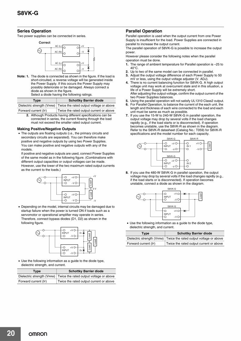
Series OperationTwo power supplies can be connected in series.
Note: 1. The diode is connected as shown in the figure. If the load is short-circuited, a reverse voltage will be generated inside the Power Supply. If this occurs the Power Supply may possibly deteriorate or be damaged. Always connect a diode as shown in the figure. Select a diode having the following ratings.
2. Although Products having different specifications can be connected in series, the current flowing through the load must not exceed the smaller rated output current.
Making Positive/Negative Outputs• The outputs are floating outputs (i.e., the primary circuits and
secondary circuits are separated). You can therefore make positive and negative outputs by using two Power Supplies.You can make positive and negative outputs with any of the models.If positive and negative outputs are used, connect Power Supplies of the same model as in the following figure. (Combinations with different output capacities or output voltages can be made. However, use the lower of the two maximum rated output currents as the current to the loads.)
• Depending on the model, internal circuits may be damaged due to startup failure when the power is turned ON if loads such as a servomotor or operational amplifier may operate in series. Therefore, connect bypass diodes (D1, D2) as shown in the following figure.
• Use the following information as a guide to the diode type, dielectric strength, and current.
Parallel OperationParallel operation is used when the output current from one Power Supply is insufficient for the load. Power Supplies are connected in parallel to increase the output current.The parallel operation of S8VK-G is possible to increase the output power.However please consider the following notes when the parallel operation must be done. 1. The range of ambient temperature for Parallel operation is –25 to
40°C.2. Up to two of the same model can be connected in parallel.3. Adjust the output voltage difference of each Power Supply to 50
mV or less, using the output voltage adjuster (V. ADJ).4. There is no current balancing function for S8VK-G. A high output
voltage unit may work at overcurrent state and in this situation, a life of a Power Supply will be extremely short.After adjusting the output voltage, confirm the output current of the two Power Supplies balances.
5. Using the parallel operation will not satisfy UL1310 Class2 output.6. For Parallel Operation, to balance the current of the each unit, the
length and thickness of each wire connected to the load and each unit must be same as much as possible.
7. If you use the 15-W to 240-W S8VK-G in parallel operation, the output voltage may drop by several volts if the load changes rapidly (e.g., if the load starts or is disconnected). If operation becomes unstable, use the S8VK-R as shown in the diagram. Refer to the S8VK-R datasheet (Catalog No.: T059) for S8VK-R specifications and the model number for each capacity.
8. If you use the 480-W S8VK-G in parallel operation, the output voltage may drop by several volts if the load changes rapidly (e.g., if the load starts or is disconnected). If operation becomes unstable, connect a diode as shown in the diagram.
• Use the following information as a guide to the diode type, dielectric strength, and current.
Type Schottky Barrier diode
Dielectric strength (VRRM) Twice the rated output voltage or above
Forward current (IF) Twice the rated output current or above
Type Schottky Barrier diode
Dielectric strength (VRRM) Twice the rated output voltage or above
Forward current (IF) Twice the rated output current or above
+V
−V
+V
−V
CorrectAC (L)
AC (N)
AC (L)
AC (N)
INPUT+V +V
0 V
−V
−V
INPUT+V
−V
Load
Load
INPUT+V
D2
D1
−V
INPUT+V
−V
Load
Load
Load
Type Schottky Barrier diode
Dielectric strength (VRRM) Twice the rated output voltage or above
Forward current (IF) Twice the rated output current or above
+V
−VINPUT
S8VK-G S8VK-R
S8VK-G
INPUT
IN 1
IN 2
Load
+V
−V
+V
−V
+V
−V
+V
−VLo
ad
INPUT
INPUT
S8VK-G
S8VK-G

S8VK-G
21
Backup OperationBackup operation is possible if you use two Power Supplies of the same model.Even if one Power Supplies fails, operation can be continued with the other Power Supply.Make sure that the maximum load does not exceed the capacity of one Power Supply.For backup operation, connect the S8VK-R as shown in the figure.
Refer to the S8VK-R datasheet (Catalog No.: T059) for S8VK-R specifications and the model number for each capacity.
In Case There Is No Output VoltageThe possible cause for no output voltage may be that the overcurrent or overvoltage protection has operated. The internal protection may operate if a large amount of surge voltage such as a lightening surge occurs while turning ON the power supply.In case there is no output voltage, please check the following points before contacting us:• Checking overload protected status:
Check whether the load is in overload status or is short-circuited. Remove wires to load when checking.
• Checking overvoltage or internal protection: Turn the power supply OFF once, and leave it OFF for at least 3 minutes. Then turn it ON again to see if this clears the condition.
Audible Noise at Power ON(120-W, 240-W, and 480-W Models)A harmonic current suppression circuit is built into the Power Supply. This circuit can create noise when the input is turned ON, but it will last only until the internal circuits stabilize and does not indicate any problem in the Product.
+V
−VINPUT
S8VK-G S8VK-R
S8VK-G
INPUT
IN 1
IN 2
Load
+V
−V
+V
−V

S8VK-G
22
Period and Terms of WarrantyWarranty PeriodThe product warranty is valid for a period of three years from the date of shipment from the factory.
Terms of WarrantyThe warranty is valid only for the following operating conditions.1. Average ambient operating temperature of the product: 40°C max.2. Average load rate: 80% max.
3. Mounting method: Standard mounting* The maximum ratings must be within the derating curve.
If the product fails for reasons attributable to OMRON within the above warranty period, OMRON will repair or replace the faulty part of the product at the place of purchase or the place where the product delivered without charge.This warranty does not cover the following types of failures.
Recommended Replacement Periods and Periodic Replacement for Preventive MaintenanceThe recommended replacement period for preventive maintenance is greatly influenced by the application environment of the product. As a guideline, the recommended replacement period is 7 to 10 years.*To prevent failures or accidents that can be caused by using a product beyond its service live, we recommend that you replace the product as early as possible within the recommended replacement period.However, bear in mind that the recommended replacement period is for reference only and does not guarantee the life of the product.
Many electronic components are used in the product and the product depends on the correct operation of these components to achieve the original product functions and performance.However, the influence of the ambient temperature on aluminum electrolytic capacitors is large, and the service life is reduced by half for each 10°C rise in temperature (Arrhenius law).When the capacity reduction life of the electrolytic capacitor is reached, the product failures or accidents may occur.We therefore recommend that you replace the product periodically to minimize product failures or accidents in advance.* The recommended replacement period applies under the following
conditions: rated input voltage, load rate of 50% max., ambient temperature of 40°C max., and the standard mounting method.
This product model is designed with a service life of 10 years minimum under the above conditions.
(1) Failures that result from handling or operation of the product under conditions or in environments that are not given in this document and not given in any other specifications exchanged between OMRON and the customer
(2) Failures that originate in causes other than the delivered product itself(3) Failures caused by disassembly, modification, or repair of the product by anyone other than OMRON(4) Failures caused by applications or uses for which the product was not originally intended(5) Failures caused by factors that could not be anticipated with the scientific or technical knowledge available when the product was shipped(6) Failures caused by other causes for which OMRON is not responsible, such as natural disasters and other acts of God
This warranty is limited to the individual product that was delivered and does not cover any secondary, subsequent, or related damages.
Terms and Conditions AgreementRead and understand this catalog.
Please read and understand this catalog before purchasing the products. Please consult your OMRON representative if you have any questions or comments.
Warranties.(a) Exclusive Warranty. Omron’s exclusive warranty is that the Products will be free from defects in materials and workmanship
for a period of twelve months from the date of sale by Omron (or such other period expressed in writing by Omron). Omron disclaims all other warranties, express or implied.
(b) Limitations. OMRON MAKES NO WARRANTY OR REPRESENTATION, EXPRESS OR IMPLIED, ABOUT NON-INFRINGEMENT, MERCHANTABILITY OR FITNESS FOR A PARTICULAR PURPOSE OF THE PRODUCTS. BUYER ACKNOWLEDGES THAT IT ALONE HAS DETERMINED THAT THE PRODUCTS WILL SUITABLY MEET THE REQUIREMENTS OF THEIR INTENDED USE.
Omron further disclaims all warranties and responsibility of any type for claims or expenses based on infringement by the Products or otherwise of any intellectual property right. (c) Buyer Remedy. Omron’s sole obligation hereunder shall be, at Omron’s election, to (i) replace (in the form originally shipped with Buyer responsible for labor charges for removal or replacement thereof) the non-complying Product, (ii) repair the non-complying Product, or (iii) repay or credit Buyer an amount equal to the purchase price of the non-complying Product; provided that in no event shall Omron be responsible for warranty, repair, indemnity or any other claims or expenses regarding the Products unless Omron’s analysis confirms that the Products were properly handled, stored, installed and maintained and not subject to contamination, abuse, misuse or inappropriate modification. Return of any Products by Buyer must be approved in writing by Omron before shipment. Omron Companies shall not be liable for the suitability or unsuitability or the results from the use of Products in combination with any electrical or electronic components, circuits, system assemblies or any other materials or substances or environments. Any advice, recommendations or information given orally or in writing, are not to be construed as an amendment or addition to the above warranty.
See http://www.omron.com/global/ or contact your Omron representative for published information.
Limitation on Liability; Etc.OMRON COMPANIES SHALL NOT BE LIABLE FOR SPECIAL, INDIRECT, INCIDENTAL, OR CONSEQUENTIAL DAMAGES, LOSS OF PROFITS OR PRODUCTION OR COMMERCIAL LOSS IN ANY WAY CONNECTED WITH THE PRODUCTS, WHETHER SUCH CLAIM IS BASED IN CONTRACT, WARRANTY, NEGLIGENCE OR STRICT LIABILITY.
Further, in no event shall liability of Omron Companies exceed the individual price of the Product on which liability is asserted.
Suitability of Use.Omron Companies shall not be responsible for conformity with any standards, codes or regulations which apply to the combination of the Product in the Buyer’s application or use of the Product. At Buyer’s request, Omron will provide applicable third party certification documents identifying ratings and limitations of use which apply to the Product. This information by itself is not sufficient for a complete determination of the suitability of the Product in combination with the end product, machine, system, or other application or use. Buyer shall be solely responsible for determining appropriateness of the particular Product with respect to Buyer’s application, product or system. Buyer shall take application responsibility in all cases.
NEVER USE THE PRODUCT FOR AN APPLICATION INVOLVING SERIOUS RISK TO LIFE OR PROPERTY OR IN LARGE QUANTITIES WITHOUT ENSURING THAT THE SYSTEM AS A WHOLE HAS BEEN DESIGNED TO ADDRESS THE RISKS, AND THAT THE OMRON PRODUCT(S) IS PROPERLY RATED AND INSTALLED FOR THE INTENDED USE WITHIN THE OVERALL EQUIPMENT OR SYSTEM.
Programmable Products.Omron Companies shall not be responsible for the user’s programming of a programmable Product, or any consequence thereof.
Performance Data.Data presented in Omron Company websites, catalogs and other materials is provided as a guide for the user in determining suitability and does not constitute a warranty. It may represent the result of Omron’s test conditions, and the user must correlate it to actual application requirements. Actual performance is subject to the Omron’s Warranty and Limitations of Liability.
Change in Specifications.Product specifications and accessories may be changed at any time based on improvements and other reasons. It is our practice to change part numbers when published ratings or features are changed, or when significant construction changes are made. However, some specifications of the Product may be changed without any notice. When in doubt, special part numbers may be assigned to fix or establish key specifications for your application. Please consult with your Omron’s representative at any time to confirm actual specifications of purchased Product.
Errors and Omissions.Information presented by Omron Companies has been checked and is believed to be accurate; however, no responsibility is assumed for clerical, typographical or proofreading errors or omissions.

OMRON Corporation Industrial Automation Company
OMRON ELECTRONICS LLC2895 Greenspoint Parkway, Suite 200 Hoffman Estates, IL 60169 U.S.A.Tel: (1) 847-843-7900/Fax: (1) 847-843-7787
Regional HeadquartersOMRON EUROPE B.V.Wegalaan 67-69, 2132 JD HoofddorpThe NetherlandsTel: (31)2356-81-300/Fax: (31)2356-81-388
Contact: www.ia.omron.comKyoto, JAPAN
OMRON ASIA PACIFIC PTE. LTD.No. 438A Alexandra Road # 05-05/08 (Lobby 2), Alexandra Technopark, Singapore 119967Tel: (65) 6835-3011/Fax: (65) 6835-2711
OMRON (CHINA) CO., LTD.Room 2211, Bank of China Tower, 200 Yin Cheng Zhong Road, PuDong New Area, Shanghai, 200120, China Tel: (86) 21-5037-2222/Fax: (86) 21-5037-2200
Authorized Distributor:
In the interest of product improvement, specifications are subject to change without notice.
CSM_6_1_0616 Cat. No. T056-E1-03 0616 (0213)
© OMRON Corporation 2013-2016 All Rights Reserved.