SWIMMING POOL & SPA HEAT PUMPS …shop.solardirect.com/pdf/pool-heaters/heat-pumps/...a Division of...
16
MEMBER Pool Heat Pump Manufacturers Association MEMBER INSTALLATION MANUAL SWIMMING POOL & SPA HEAT PUMPS WARNING: Specifications may change without notice. NATIONAL POOL & SPA INSTITUTE V6.0-AT-A © 2001 Aquatherm Heat Pumps a division of Calorex U.S.A. LLC SWIMMING POOL & SPA HEAT PUMPS OFF OFF OFF OFF POOL SPA WATER IN WATER OUT ELEC. PANEL WARNING: Specifications may change without notice. Intended for licensed factory authorized installers only! Users should review separate owners operational manual. INFORMATION PLACEMENT PLUMBING ELECTRICAL Model AT800 AT600 & AT400 “BLACK CABINET” with ANALOG PROLOGIC CONTROL SERIES ONLY PROLOGIC CONTROL PROLOGIC CONTROL PROLOGIC CONTROL NOTICE: UNIT REQUIRES TWO, 2 INCH FEMALE ADAPTORS FOR PLUMBING CONNECTIONS !
-
Upload
nguyenphuc -
Category
Documents
-
view
220 -
download
1
Transcript of SWIMMING POOL & SPA HEAT PUMPS …shop.solardirect.com/pdf/pool-heaters/heat-pumps/...a Division of...

HEATING
POOLSPA
OFF
POWER
FAULT
NO WATERFLOW
PROLOGIC CONTROL
6060
6565
70707575
8080
8585
9090
9595
100100
105105
6060
6565
70707575
8080
8585
9090
9595
100100
105105
MEMBER
PoolHeatPumpManufacturersAssociationM
EM
BE
R
INSTALLATION MANUAL
SWIMMING POOL & SPAHEAT PUMPS
WARNING: Specifications may change without notice.
NATIONALPOOL & SPAINSTITUTE
V6.0-AT-A © 2001 Aquatherm Heat Pumps a division of Calorex U.S.A. LLC
SWIMMING POOL & SPAHEAT PUMPS
OFF
OFF
OFF
OFF POOLSPA
WATERIN
WATEROUT
ELEC.PANEL
WARNING: Specifications may change without notice. Intended for licensed factoryauthorized installers only! Users should review separate owners operational manual.
INFO
RMAT
ION
PLA
CEM
ENT
PLU
MBI
NG
ELEC
TRIC
AL
Model AT800 AT600 & AT400“BLACK CABINET” with ANALOG PROLOGIC CONTROL SERIES ONLY
HEATING
POOLSPA
OFF
POWER
FAULT
NO WATERFLOW
PROLOGIC CONTROL
6060
6565
70707575
8080
8585
9090
9595
100100
105105
6060
6565
70707575
8080
8585
9090
9595
100100
105105
HEATING
POOLSPA
OFF
POWER
FAULT
NO WATERFLOW
PROLOGIC CONTROL
6060
6565
70707575
8080
8585
9090
9595
100100
105105
6060
6565
70707575
8080
8585
9090
9595
100100
105105
HEATING
POOLSPA
OFF
POWER
FAULT
NO WATERFLOW
PROLOGIC CONTROL
60
60
65
65
70
70
75
75
80
80
85
85
90
90
95
95
100
100
105
105
60
60
65
65
70
70
75
75
80
80
85
85
90
90
95
95
100
100
105
105
NOTICE: UNIT REQUIRES TWO,2 INCH FEMALE ADAPTORSFOR PLUMBING CONNECTIONS !

Written & Illustrated by Michael Glore
Table of Contents
A. Introduction ............................................................................................1. Unit Description2. Explanation of Heat Pump Heat Transfer3. Efficiency Comparisons
B. Unit Placement .........................................................................................1. Placement Requirements2. Air Flow Clearances & Service Access3. Gutters, Overhangs & Sprinklers
C. Plumbing- Water Connections ................................................................1. Basic Plumbing2. Chlorinator & Chemical Feeder Requirements3. Freezing Condition Plumbing Requirements4. External Bypass Requirements Over 70 G.P.M.5. Pool/Spa Combination Plumbing6. Plumbing with Solar7. Plumbing Above or Below Water Level8. Optional Flow Switch Installation
D. Electrical Connections .............................................................................1. Supply Wiring, Single Phase, 240V2. Wire & Breaker Size Requirements3. Bonding Requirements4. 208 Supply Voltage Transformer Wiring Change5. Factory Specification Chart6. Wiring Diagrams - Single & 3 Phase7. Interfacing with External Controls, Jandy & Compool
E. Control Panel Information & Operation & Description ...........................1. Heater Controls2. Indicator Light Explanations
3. Operation Sequence & Troubleshooting Flow Chart
Page 3
Pages 4
Pages 5 - 7
Page 8 - 13
Page 14 - 15
a Division of Calorex USA L.L.C.2213 Andrea Lane Ft. Myers FL 33912
888-297-3826 941-482-0606www.aquathermheatpumps.com
www.calorexusa.com
HEAT PUMPS

HEATING
POOLSPA
OFF
POWER
FAULT
NO WATERFLOW
PROLOGIC CONTROL
6060
6565
70707575
8080
8585
9090
9595
100100
105105
6060
6565
70707575
8080
8585
9090
9595
100100
105105
Page 3
Unit Description AIR DISCHARGE FANWARNING: ROTATING BLADE KEEP
HANDS & HAIR CLEAR!
THERMOSTATCONTROLSPOOL/SPA
STATUSINDICATOR
LIGHTS
WATER OUT2” THREADED
MALE PIPE
REFRIGERANTSERVICE VALVESDO NOT OPEN !
WATER IN2” THREADED
MALE PIPE
SERIALNUMBER
PLATE
ELECTRICALSUPPLY WIRINGACCESS PANEL
“KEEP OUT”
ELECTRICALINSTALLATION
PORTS
POOL/OFF/SPASELECT SWITCH
DANGER FROM ELECTRICALSHOCK & ROTATING FAN !
SHUT OFF ALL POWERBEFORE SERVICING !
CAUTION: MORE THAN ONEDISCONNECTION MAY BE
REQUIRED TO ELIMINATE ALLPOWER TO THIS UNIT INCLUDINGPOWER TO THE OPTIONAL TIME
CLOCK OVERRIDE !
WARNING
A swimming pool & spa pump utilizes proven refrigerant technology to capture the heat in theoutside air and transfers it to the pool water. Refrigerant is used because of its ability to absorb andtransfer heat energy. The fan circulates air through the outer evaporator air coil that acts as a heatcollector. The liquid refrigerant in the air coil absorbs theavailable heat in the ambient air, transforming it into agas. The refrigerant gas is thenpumped into the compressor.When this warmed gas is com-pressed, it intensifies or concen-trates the heat, like a magnifyingglass in the sun.This intensely hot gas is thenpumped into the heat ex-changer condenser, where theactual heat transfer takes place.As the pool water passesthrough the heat exchanger, thehot gas gives up its heat to the cooler pool wa-ter. The refrigerant returns to a liquid state andis pumped through the expansion valve theninto the evaporator air coil to start the process allover again.
How Does A Heat Pump Warm My Pool ?
How Efficient Is It ?This graph is a operational cost comparison for equalamounts of pool heat. As you can see heat pump isthe most efficient way to heat your pool.
Compared to L.P. gas heaters, a heat pump produces5 to 6 times more heat for every $1.00 you spendon operation.
FAN
WARMAIR
COOLAIR
COMPRESSOR
POOL
WATERPUMP
FILTER
HEAT EXCHANGERCONDENSER
EXPANSIONVALVE
EVAPORATORAIR COIL
WARMEDGAS
NOTICE: UNIT REQUIRES TWO, 2 INCHFEMALE ADAPTORS FOR PLUMBINGCONNECTIONS

1. To allow for proper condensation drain-age, use a level slab to elevate the heat pumpto at least the same height as the pool filtersystem slab or 2 to 3 inches “minimum” abovegrade.
2. Allow the minimum air flow clearanceson top and the sides as shown here. Makesure the unit can “breathe” well. Do not in-stall indoors or where the discharge air canaccumulate and be drawn back through theheater. Make sure the front is accessiblefor future service.
3. Keep sprinkler heads at least 6 feet awayfrom the heat pump. Do not allow the sprin-kler to spray the unit in any way to preventdamage.
4. If the unit is installed under a sharp roofpitch or under a roof valley without a gutter,a gutter or diverter should be fitted to pre-vent excessive water from rushing through theunit.
5. Keep all plants and shrubs trimmed awayfrom the heater to the minimum clearancesshown here to prevent air coil damage.
6. If the heater is installed above or belowthe pool water level by more than 3 feet youmay require an external water flow switch.See the bottom of page 7 for more informa-tion.
BASECONCRETE OR
PREFAB
Minimum Air Flow& Access Clearances
Heat Pump Placement & Clearances
AIR COILAIR FLOW INON 3 SIDES
FAN DISCHARGEAIR FLOW OUT
HEATING
POOLSPA
OFF
POWER
FAULT
NO WATERFLOW
PROLOGIC CONTROL
6060
6565
70707575
8080
8585
9090
9595
100100
105105
6060
6565
70707575
8080
8585
9090
9595
100100
105105
WATER IN-OUT PORTINDICATOR LABEL
Page 4
2” THREADED MALEPIPING CONNECTIONS

Page 5
Plumbing & Water Connections - 2” Threaded MaleFor a simple pool only or spa only, install the plumbing piping as shown:Connections from factory are 2” threaded male pipe, requiring 2 inch female adaptors, see diagram.Use teflon tape and pipe sealer. Tighten hand tight plus 1/2 snug tight with pliers.Water IN on the RIGHT, Water OUT on the LEFT,PLUMB AFTER the FILTER & BEFORE any CHLORINATORS or CHEMICAL FEEDERS
Be sure to install a CHECK VALVE & CHEMICAL TRAP LOOP as shown. The loop should be at least6 to 8 inches above the chlorinator/feeder top to prevent chlorine backup into the heater when thewater pump is off. Install a 2# check valve on the heater side of the loop as shown above toprevent chlorine from damaging it. All feeders should be installed at the same or below theheater piping elevation to prevent chemical back up into the heater.DO NOT : Install the heater down stream from any chemical feeders.DO NOT : Allow chemical feeders on the suction side of the water pump.DO NOT : Allow any chemicals or chlorine to be fed through the skimmer.DO NOT : Allow the pool water pH to go below 7.4. DO NOT allow the alkalinity to go below 90 p.p.m.DO NOT : Allow the chlorine to go above 5 p.p.m. for extended periods. Chemical damage is not coveredby and may void warranty.
Bypass for Flow Rates Over 70 G.P.M.Typically the automatic internal water by-pass can handle up to a 1.5 H.P. waterpump or 70 G.P.M. If the water pump ex-ceeds 1.5 H.P. then install either of the op-tional bypasses as shown below.
Plumb multiple units as shown below. Use flowmeters on each WATER OUT line if two or moreunits are plumbed together.
Freezing Condition PlumbingIn areas where extended freezing conditions exist, the heater must beplumbed as shown so it can be winterized. Water left inside the heaterwill freeze and cause damage. Plumb in a union, shut off valve, a boilerdrain and a air petcock valve on the water in and water out lines asshown here. Isolate the heater with the shut off valves and use pressur-ized air to clear the heat exchanger of all water. In areas where freezingconditions are temporary, the water pump should be set to run 24 hoursto prevent freezing. Freeze damage will void warranty.
Multi Unit Water Connections
OFF
Ball Valve orJandy™ 3-Way
The installation of a flow meter on the WATEROUT line is suggested. Adjust the bypass todivert a minimum of 40 to 50 G.P. M. throughthe heater. Flow meters should be installed perthe manufacturers instructions.
Use ball valves to balance the water flow through eachunit. Using T’s, caps and a minimum 6 inch pipe exten-sion on the plumbing manifold will help equalize thewater flow better than 90˚’s. Flow meters should be in-stalled per the manufacturers instructions.
See page 6 for pool/spaplumbing diagrams.

Page 6
For a separate pool and spa not con-nected, and does not have a spill-over. Where the pool and the spahave separate pump & filter systemsbut using the same heater. If the waterpump exceeds 1.5 H.P. then installeither of the optional bypasses asshown on page 5.
OFF
OFF
OFF
OFF
OFF
OFF
OFF POOLSPA
Plumbing & Water Connections for Pool/Spa CombinationsFor a connected pool and spa, where the spa has a spill over type waterfall into the pool. Whereone pump and one heater is used for either the pool or the spa. If the water pump exceeds 1.5H.P. then install either of the optional bypasses as shown on page 5.
Plumbing & Water Connections for Separate Pool & Spa
SEE CHLORINATOR LOOP & CHECKVALVE REQUIREMENT ON PAGE 5.
SEE CHLORINATOR LOOP & CHECKVALVE REQUIREMENT ON PAGE 5.

Page 7
1
2
3
4
5
6
7
8
9
10
11
12
1
2
3
4
5
6
7
8
9
10
11
12 .1 8
LOAD
1
2
5
3
4
6
Plumbing & Water Connections with SolarPlumbing for a system where asolar pool heater is installed. It isstrongly advised that an auto-matic solar control device beused when used with the heatpump.
The heat pump and solar can beoperated together. The heatpump will share the heating loadwith the solar. If there is no heatcoming from the solar panels, thesolar control device will turn offthe solar by rotating the motorvalve, otherwise it should beturned off manually. The heatpump will then maintain thepool/spa temperature.
To use the heat pump as a backupto the solar, set the heat pumpthermostat 2 to 4 degrees belowthe solar’s target temperature set-ting. Therefore, if the solar is notmaintaining water temperature,the heat pump will come on toassist the solar. Some thermostatfine tuning may be required bythe user.
If you install the heat pump above or below the pool or spa water level by more than 3 feet, the internalwater pressure switch may be effected by the static pressure of the pool water. In some cases it maybe necessary to install a water FLOW switch. The water flow switch is not effected by changes inwater pressure but only water movement. We suggest installing the Grid Brand Model 20 or 25, externalflow switch and disabling the internal water pressure switch. Plumb in the flow switch as shown here.Then run a THREE wire insulated cable from the flow switch into the heater and attach to the existingwater pressure switch leads located behind the large service panel and wire as shown below.REVIEW PAGE 8 FOR SIMILAR ACCESS TO LARGE ELECTRICAL SERVICE COMPARTMENT BE-FORE CONTINUING. REVIEW UNIT WIRING DIAGRAM ON PAGE 10 & 11 ALSO !
Plumbing & Water Connections for Above or Below Water Level
INOU
T
OFF
OFF
JAND
Y ™
If the water pump exceeds 1.5 H.P. theninstall either of the optional bypasses asshown on page 5.
NOTE: If the solar is operated on cloudy days, whileraining, at night or at low air temperatures, it may coolthe pool or spa. A automatic solar control will shut thesolar off when there is no solar activity, otherwise itshould be shut off manually during these times.

Electrical Connections & Wiring for Analog Control Models
BREAKER SIZE RECOMMENDATIONMODEL AT800 & A T600: 50 AMPS
MODEL AT400: 40 AMPSMINIMUM WIRE SIZE for ALL MODELS
#8 A.W.G. COPPER STRANDED OR LARGER
TRANSFORMER WIRING CHANGE FOR 208 VOLTAGENOTE: If the power supply is 208 and not 220 volts, youmust make a simple wiring change to the low voltageside of the transformer. See diagram on transformer.
WARNING ! 3 Phase Compressor Models Are RotationSensitive! Use Refrigerant Gages! Do Not Go By Fan Ro-tation Since It Will Always Be Single Phase! *SEE PAGE11 FOR THREE PHASE WIRING DIAGRAM*
The AT800, AT600 & AT400 re-quire a MINIMUM of #8 A.W.G.copper stranded wire, (orlarger if needed.)
You must increase the wire sizeunder low voltage, high ampdraw, and/or long-run condi-tions as required by NationalElectrical Code.
You must bond the heater ex-ternally to the pool/spa steel asrequired by local codes. Abonding lug is located on thebottom front exterior of the unit.NOTE : See wiring diagrams onpages 10 & 11
See page 9 for factory specifi-cation listings also.
DANGER FROM ELECTRICAL SHOCK & ROTATING FAN !SHUT OFF ALL POWER BEFORE REMOVING ANY PANELS !CAUTION: MORE THAN ONE DISCONNECTION MAY BEREQUIRED TO ELIMINATE ALL POWER TO UNIT INCLUD-ING POWER TO THE OPTIONAL TIME CLOCK OVERRIDE !
This unit is equipped with astart-up time delay on thecompressor only. Wheneverthe unit is started or re-started, there will be a 5 to 7minute delay before thecompressor will operate.
Page 8

* Optimum output & efficiency typical of Florida conditions. Ratingsoutside the scope of P.H.P.M.A. heat pump pool heater certificationprogram. ** Rated and certified in accordance with A.S.H.R.A.E.standard 146-1998 and P.H.P.M.A. addendum test procedure.
Factory Specifications
MEMBER
NATIONALPOOL & SPAINSTITUTE
PoolHeatPumpManufacturersAssociationM
EM
BE
R
3 Phase Compressor Is Rogation Sensitive! Use Refrigerant Gages!Do Not Go By Fan Rotation Since It Will Always Be Single Phase!
WARNING: THREE PHASE MODELS:
Model NumberBTU Output
Coefficient of PerformanceCopeland Scroll™ Compressor
Heat Exchanger CondenserAir Coil Evaporator
Fan MotorAir Flow
Kilowatt InputElectrical (208/240v/60Hz)
Typical Running AmpsMinimum Circuit Ampacity
Min/Max Breaker SizeMin. Copper Stranded Wire Size
Min/Max Water FlowWater Plumbing
Refrigerant ChargeCabinet Construction
Ship WeightDimensions
AT600 AT400108,000*/102,000** 92,000*/84,000**6.0*/4.9** 6.4*/5.5**ZR67 w/ Receiver Tank ZR54 w/ Receiver Tank Cupronickel Alloy-Water / Copper-Exterior Oversized: Copper Tube w Lanced Fin 1/4 H.P. @ 1.6 Amps 4000 C.F.M. w/ Cowling Venturi5.8 Kw/Hour 4.4 Kw/HourSingle Phase Single Phase27.4 Amps 20.4 Amps37 Amps 35 Amps40/50 Amps 35/40 Amps#8 A.W.G.or Larger #8 A.W.G.or Larger20/70 GPM, Over 70 G.P.M. or 1.5 H.P. Add External Bypass 2” Full Flow w Internal Automatic BypassR22 R22 Corrosion Proof Molded ABS305 Lbs. 279 Lbs.35H x 31W x 34L 29H x 31W x 34L
Page 9
Model NumberBTU Output
Coefficient of PerformanceCompressor
Heat Exchanger CondenserAir Coil Evaporator
Fan MotorAir Flow
Kilowatt InputElectrical (208/240v/60Hz)
Typical Running AmpsMinimum Circuit Ampacity
Min/Max Breaker SizeMin. Copper Stranded Wire Size
Min/Max Water FlowWater Plumbing
Refrigerant ChargeCabinet Construction
Ship WeightDimensions
AT800112,000*/104,000**6.3*/5.3**Copeland Scroll™ ZR67 w/ Receiver TankCupronickel Alloy-Water / Copper-ExteriorOversized Mt. Holly Gold™ Polyester Clad1/4 H.P. @ 1.6 Amps4200 C.F.M. with Built In Cowling Venturi5.5 Kw/HourSingle & Three Phase26.1 Amps / (18.5 Amps @ 3 Phase)37.8 Amps / (25.4 Amps @ 3 Phase)40/50 Amps / (25/35 Amps @ 3 Phase)#8 A.W.G. or Larger20/70 GPM Over 70 G.P.M. or 1.5 H.P. Add External Bypass2” Full Flow w Internal Automatic BypassR22Corrosion Proof Molded ABS324 Lbs.37H x 31W x 36L
a Division of Calorex USA L.L.C.2213 Andrea Lane Ft. Myers FL 33912
888-297-3826 941-482-0606www.aquathermheatpumps.com
www.calorexusa.com
HEAT PUMPS
Specifications may change without notice.© 2001 Aquatherm Heat Pumps

Wiring Diagram AT800, AT600 & AT400 “Prologic”Analog Control ModelsSingle Phase, 208/240 Volts, 60 Hz.
Wiri
ng d
iagr
ams
may
cha
nge
with
out n
otic
e.
Page 10

Page 11
WARNING: THREE PHASE MODELS: 3 Phase Compressor Is Rotation Sensitive! Use RefrigerantGages! Do Not Go By Fan Rotation Since It Will Always Be Single Phase!
Wiring Diagram for “3-Phase” Model AT800 & AT600, 208/240 Volts, 60 Hz,with “Prologic” Analog Control
Wiri
ng d
iagr
ams
may
cha
nge
with
out n
otic
e.

To interface the “Prologic” analog control heat pump models with the Jandy™ AquaLink RSseries or Compool, run a 2 wire (16 A.W.G. or larger) insulated cable from the device to the heatpump. If you are using a Jandy AquaSwitch or JI2000 control use a 3 wire cable. Review wiringdiagram on page 10.
Remove the 6 screws from the heaters front service access panel and open. Look for a white,two position wire terminal located inside the top portion of the electrical compartment and ismounted on the rear wall. (Do not confuse it with the 4 position, white terminal blockabove it !) Locate, remove and discard the orange wire loop attached at the bottomend of this terminal. Then, attach the 2 wire cable coming from the AquaLink RS or the Compoolcontrol to the 2 position terminal where the orange loop was prior, see page 13.
NOTE for AquaLink RS andCompool: Turn both heater ther-mostats all the way up and setthe mode selector switch topool and do not use the heatercontrols as the Jandy orCompool now has thermostatcontrol over the heater.
For AquaSwitch and JI2000:The heater’s thermostats still con-trol the heater and should bepreset to the desired pool andspa temperature. The pool/spaselect switch should be left onpool mode and will be inactiveas the AquaSwitch or JI2000 hasswitching control over theheater.
Page 12
Interfacing “Prologic” Analog Control Models with:Jandy™ AquaLink RS, AquaSwitch, JI 2000 & Compool™
1
25
3
46
1
25
3
46
E10
E6
OR
OR
OR
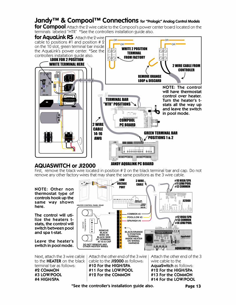
Jandy™ & Compool™ Connections for “Prologic” Analog Control Models
for AquaLink RS Attach the 2 wirecable to positions #1 and position # 2on the 10 slot, green terminal bar insidethe AquaLink’s power center. *See thecontrollers installation guide also.
for Compool Attach the 2 wire cable to the Compool’s power center board located on theterminals labeled “HTR” *See the controllers installation guide also.
Attach the other end of the 3wire cable to theAquaSwitch as follows:#12 For the HIGH/SPA#13 For the COMMON#14 For the LOW/POOL
AQUASWITCH or JI2000First, remove the black wire located in position # 2 on the black terminal bar and cap. Do notremove any other factory wires that may share the same positions as the 3 wire cable.
Next, attach the 3 wire cableto the HEATER on the blackterminal bar as follows:#2 COMMON#3 LOW/POOL#4 HIGH/SPA
Attach the other end of the 3 wirecable to the JI2000 as follows:#10 For the HIGH/SPA#11 For the LOW/POOL#12 For the COMMON
*See the controller’s installation guide also. Page 13
OR
OR
OR
OR
12 11 10 9 8 7 6 5 4 3 2 1
1
2
3
4
5
6
7
8
9
10
11
12
NOTE: Other nonthermostat type ofcontrols hook up thesame way shownhere.
The control will uti-lize the heaters t-stats, the control willswitch between pooland spa t-stat.
Leave the heater’sswitch in pool mode.
NOTE: The controlwill have thermostatcontrol over heater.Turn the heater’s t-stats all the way upand leave the switchin pool mode.

TEMPERATURE CONTROLS: The top Thermostat controls the pool temperature. Thebottom Thermostat controls the spa temperature. If you do not have a spa you can usethe two thermostats as a high and low temperature preset.
THERMOSTAT/OFF SWITCH- POOL/OFF/SPA: The Thermostat/Off Switch determineswhich thermostat is active, up for pool, down for spa. You can disable the heater byplacing the selector switch in the center “OFF” position.
GREEN POWER LIGHT: This light indicates that the heater has control power. WARN-ING: This is not a line power indicator and caution should be used since more than onepower disconnection may be required to isolate the heater electrically. WARNING: Ifthe optional Time Clock Override is installed, you must shut off the water pumps mainpower disconnect as well.
BLUE HEATING LIGHT: This light indicates that the unit is heating and the compressoris running. The compressor starts after a 5 to 7 minute time delay. NOTE: The waterpump must be running at the same time in order for the heater to run.
AMBER NO WATER FLOW LIGHT: This light indicates there is no water flow through theheater. The heater is designed to shut off whenever the water pump is not pumpingwater through the heater. If this light is on while the water pump is running, the waterpump may not be supplying enough flow for the heater to operate properly. Duringnormal operation the heater turns off and on with the water pump, (as long as thethermostat is calling for heat).
RED FAULT LIGHT: This light indicates that the internal safety control system has dis-abled the heater. If either the high or low refrigerant pressure switch has tripped thislight will come on. NOTE: During cold weather where the air temperature dropsbelow approximately 45 to 50 degrees (depending on humidity), the low refrig-erant pressure switch (or defrost control), is designed to disable the heater. Inthis “defrost mode” the fan and compressor will shut off. When the defrostswitch resets for whatever reason the fan will restart, then after a 5 to 7 minutetime delay the compressor will attempt to restart. In some case where the airtemperature are in a borderline range, the heater my cycle on & off in an at-tempt to reset. The heater should be shut off when the air temperature is ex-pected to drop below the operational range for an extended period. The highrefrigerant pressure switch is designed to shut the compressor and fan off if a heatbuildup occurs for what ever reason. Typically the high refrigerant pressure switch willtrip if the water flow through the heater is restricted. It may also trip if the air flow isrestricted through the heater.
NOTES: The heater will never run without water running through it from the filter pump.The heater will not heat faster if you turn the thermostat knob up higher.
“Prologic” Analog Control Panel Information
Page 14

Operational Sequence & Troubleshooting Flow Chartfor “Prologic” Analog Control Models
Page 15
Water PumpStarts Flowing
Water FlowThrough
Heater Confirmed
Heater Stays Off
Fault Check OKFault Light Off
No Water FlowLight On
Heater Off
Heater SystemFault Check
220V PowerTo Heater On
Power Light On
Water Rises ToSet Temp
Water NotFlowing Through
Heater
Water Pump TimerMay Be Off
Turn On Water Pump
5 to 7 Min.Time Delay Period
Activated
Heater Shuts Off Heating Light Off
Water PumpTimer Activates
Compressor DoesNot Activate
After Delay Period
Water Temperatureis Below Setting
Water Temperatureis Above Setting
Fault Found, RedFault Light On
Heater BlowsCooled
Air From Top
Heater ProducesCondensationif Air is Humid
Clean Pool FilterCheck Water Valves
Pool or SpaLooses Temp.
ThermostatActivates
Allow Time DelayTo Cycle5 Times
Callfor
Service
CompressorStarts, Blue
Heating Light ON
ThermostatDetermines
Pool/Spa Temp
Fan StartsRunning
Unit RestartsHeating Light ON
Unit Shuts Offor Fan Restarts
or HeaterStays Offor Cycles
Low Water FlowThrough Heater
In Defrost ModeBelow Approx.45-50˚F Air Temp
Clean PoolFilters & CheckWater Valves
Wait for Air Tempto Rise &Try Again
5-7 Min. DelayCompressor RestartsBlue Heating Light On
Call forService
“If Then”Heater Will NotStart or Cycles

MEMBER
NATIONALPOOL & SPAINSTITUTE
PoolHeatPumpManufacturersAssociationM
EM
BE
R
a Division of Calorex USA L.L.C.2213 Andrea Lane Ft. Myers FL 33912
888-297-3826 941-482-0606www.aquathermheatpumps.com
www.calorexusa.com
HEAT PUMPS
Specifications may change without notice.© 2001 Aquatherm Heat Pumps a Division of Calorex USA L.L.C.