Swimming 5 - Colorado Time Systems
86
Swimming 5 For The System 5 Sports Timer Software User Guide F506 Rev. 0698 1551 East Eleventh Street Loveland, Colorado 80537-5056 Customer Service Department Phone: 970-667-1000 ext. 256 Toll Free U.S. and Canada 800-287-0653 Fax: 970-667-1032
Transcript of Swimming 5 - Colorado Time Systems

Swimming 5
For The System 5 Sports TimerSoftware User Guide
F506 Rev. 0698
1551 East Eleventh StreetLoveland, Colorado 80537-5056
Customer Service DepartmentPhone: 970-667-1000 ext. 256Toll Free U.S. and Canada 800-287-0653Fax: 970-667-1032

Federal Communications CommissionR.F. Interference Statement
NOTE:
This equipment has been tested and found to comply with the limits for a Class A digital device, pursuant to Part 15 of the FCCRules. These limits are designed to provide reasonable protection against harmful interference when the equipment is operated in acommercial environment. This equipment generates, uses and can radiate radio frequency energy and, if not installed in accordancewith the instruction manual, may cause harmful interference to radio communications. Operation of this equipment in a residentialarea is likely to cause harmful interference in which case the user will be required to correct the interference at his/her own expense.
CAUTION TO USER:
Changes or modifications to the equipment not expressly approved by Colorado Time Systems, llc. could void the FCC complianceand the user's authority to operate the equipment.
INSTRUCTION TO USER:
To determine if this equipment is interfering with radio or television reception, turn it on and off while observing the radio or televi-sion receiver. If interference is observed, try to correct it with one or more of the following measures:
-Reorient the receiving antenna.-Move the equipment away from the receiver. -Plug the equipment into a different electrical outlet so that the equipment and receiver are on different branch circuits. -Ensure that card mounting screws, attachment connector screws, and ground wires are tightly secured. -Ensure that card slot covers are in place on any system unit used with the equipment.
If necessary, consult your dealer service representative for additional suggestions.
Colorado Time Systems
Corporate Office1551 East 11th StreetLoveland, CO 80537 USA
Sales : 800-279-0111 or +1 970-667-1000
Service: 1-800-287-0653 x256 or +1 970-667-1000 x256Service Fax: 970-667-1032
Web: www.coloradotime.comShop online: http://secure.coloradotime.comEmail: [email protected]
IBM is a registered trademark of IBM Corporation. Epson is a registered trademark of Epson America, Inc. Lime-A-Way is a registered trademarkof Benckiser Consumer Products, Inc.
Part Number F506, Rev. 0698©1998. Colorado Time Systems, llc. All rights reserved.

1 IntroductionDear Customer: . . . . . . . . . . . . . . . . . . . . . . . . . . . . . . . . . . . . . . 1-1Getting to Know Your System 5. . . . . . . . . . . . . . . . . . . . . . . . . . . 1-2
Scope of the Manual . . . . . . . . . . . . . . . . . . . . . . . . . .1-4Contents . . . . . . . . . . . . . . . . . . . . . . . . . . . . . . . . . . . . .1-4
2 Swimming System Hardware SetupGeneral Guidelines . . . . . . . . . . . . . . . . . . . . . . . . . . . . .2-1
Start Systems . . . . . . . . . . . . . . . . . . . . . . . . . . . . . . .2-1Finish Systems . . . . . . . . . . . . . . . . . . . . . . . . . . . . . .2-2System Layout Diagrams . . . . . . . . . . . . . . . . . . . . . .2-3System 5 I/O Panel . . . . . . . . . . . . . . . . . . . . . . . . . . .2-4
Scoreboard Configuration . . . . . . . . . . . . . . . . . . . . . . . .2-6Introduction . . . . . . . . . . . . . . . . . . . . . . . . . . . . . . . .2-6Single-Line Scoreboard . . . . . . . . . . . . . . . . . . . . . . . .2-6Multi-Line Scoreboard . . . . . . . . . . . . . . . . . . . . . . . .2-7System Test . . . . . . . . . . . . . . . . . . . . . . . . . . . . . . . . .2-9
3 Tutorial Some Assumptions . . . . . . . . . . . . . . . . . . . . . . . . . . . . . .3-1Before the Race . . . . . . . . . . . . . . . . . . . . . . . . . . . . . . . .3-1Starting the Race . . . . . . . . . . . . . . . . . . . . . . . . . . . . . . .3-2
Using the +Touch Key . . . . . . . . . . . . . . . . . . . . . . .3-2Using Split Arm . . . . . . . . . . . . . . . . . . . . . . . . . . . .3-3Using Finish Arm . . . . . . . . . . . . . . . . . . . . . . . . . . .3-4
Finishing the Race . . . . . . . . . . . . . . . . . . . . . . . . . . . . . .3-4
4 ReferenceBasic Operation . . . . . . . . . . . . . . . . . . . . . . . . . . . . . . .4-1
Self Test/Loading Swimming . . . . . . . . . . . . . . . . . . .4-1User Interface . . . . . . . . . . . . . . . . . . . . . . . . . . . . . . .4-2Warning Messages . . . . . . . . . . . . . . . . . . . . . . . . . . . .4-2Timing Problems . . . . . . . . . . . . . . . . . . . . . . . . . . . .4-2Modes of Operation . . . . . . . . . . . . . . . . . . . . . . . . . . .4-3Timing Corrections . . . . . . . . . . . . . . . . . . . . . . . . . . .4-4Relay Judging . . . . . . . . . . . . . . . . . . . . . . . . . . . . . . .4-5
Keyboard . . . . . . . . . . . . . . . . . . . . . . . . . . . . . . . . . . . . .4-6Lane On-Off . . . . . . . . . . . . . . . . . . . . . . . . . . . . . . . .4-6Finish Arm . . . . . . . . . . . . . . . . . . . . . . . . . . . . . . . . .4-6Split Arm . . . . . . . . . . . . . . . . . . . . . . . . . . . . . . . . . .4-6Start . . . . . . . . . . . . . . . . . . . . . . . . . . . . . . . . . . . . . .4-7Store/ Print . . . . . . . . . . . . . . . . . . . . . . . . . . . . . . . . .4-7Next Heat . . . . . . . . . . . . . . . . . . . . . . . . . . . . . . . . . .4-7Next Event . . . . . . . . . . . . . . . . . . . . . . . . . . . . . . . . .4-7Edit Event/Heat . . . . . . . . . . . . . . . . . . . . . . . . . . . . .4-8Event Mode . . . . . . . . . . . . . . . . . . . . . . . . . . . . . . . . .4-8Edit/DQ . . . . . . . . . . . . . . . . . . . . . . . . . . . . . . . . . . . .4-8+ Touch . . . . . . . . . . . . . . . . . . . . . . . . . . . . . . . . . . .4-8- Touch . . . . . . . . . . . . . . . . . . . . . . . . . . . . . . . . . . . .4-9Events . . . . . . . . . . . . . . . . . . . . . . . . . . . . . . . . . . . . .4-9Reset . . . . . . . . . . . . . . . . . . . . . . . . . . . . . . . . . . . . . .4-9
Numeric Keypad . . . . . . . . . . . . . . . . . . . . . . . . . . . . . . .4-10Enter . . . . . . . . . . . . . . . . . . . . . . . . . . . . . . . . . . . . . .4-10C/E . . . . . . . . . . . . . . . . . . . . . . . . . . . . . . . . . . . . . . .4-10
Console Keys . . . . . . . . . . . . . . . . . . . . . . . . . . . . . . . . . .4-10Enter . . . . . . . . . . . . . . . . . . . . . . . . . . . . . . . . . . . . .4-11
TOCi
Table of Contents

Quit . . . . . . . . . . . . . . . . . . . . . . . . . . . . . . . . . . . . . . .4-11Battery Check . . . . . . . . . . . . . . . . . . . . . . . . . . . . . . .4-11Help . . . . . . . . . . . . . . . . . . . . . . . . . . . . . . . . . . . . . .4-11
Softkeys . . . . . . . . . . . . . . . . . . . . . . . . . . . . . . . . . . . . . .4-12Print . . . . . . . . . . . . . . . . . . . . . . . . . . . . . . . . . . . . . .4-12Display . . . . . . . . . . . . . . . . . . . . . . . . . . . . . . . . . . . .4-14Scoreboard . . . . . . . . . . . . . . . . . . . . . . . . . . . . . . . . .4-15Setups . . . . . . . . . . . . . . . . . . . . . . . . . . . . . . . . . . . . .4-17Setups Softkey Menu . . . . . . . . . . . . . . . . . . . . . . . . .4-17Stored Data . . . . . . . . . . . . . . . . . . . . . . . . . . . . . . . .4-30Misc . . . . . . . . . . . . . . . . . . . . . . . . . . . . . . . . . . . . . . .4-34
Appendix A MaintenanceCustomer Service . . . . . . . . . . . . . . . . . . . . . . . . . . . . . . .A-1Factory Maintenance . . . . . . . . . . . . . . . . . . . . . . . . . . . .A-1Routine Maintenance . . . . . . . . . . . . . . . . . . . . . . . . . . . .A-2
System 5 . . . . . . . . . . . . . . . . . . . . . . . . . . . . . . . . . . .A-2Connectors . . . . . . . . . . . . . . . . . . . . . . . . . . . . . . . . .A-2Cables . . . . . . . . . . . . . . . . . . . . . . . . . . . . . . . . . . . . .A-3Start Systems . . . . . . . . . . . . . . . . . . . . . . . . . . . . . . .A-4Scoreboard . . . . . . . . . . . . . . . . . . . . . . . . . . . . . . . . .A-4Printer . . . . . . . . . . . . . . . . . . . . . . . . . . . . . . . . . . . .A-4
Troubleshooting . . . . . . . . . . . . . . . . . . . . . . . . . . . . . . .A-4Troubleshooting Chart . . . . . . . . . . . . . . . . . . . . . . . .A-6
References . . . . . . . . . . . . . . . . . . . . . . . . . . . . . . . . . . . .A-9Start System . . . . . . . . . . . . . . . . . . . . . . . . . . . . . . .A-9Finish System . . . . . . . . . . . . . . . . . . . . . . . . . . . . . .A-10Wiring System . . . . . . . . . . . . . . . . . . . . . . . . . . . . . .A-11
Appendix B Test/Programming MenuAccessing the Test/Programming Menu . . . . . . . . . . . . .B-1Running Tests . . . . . . . . . . . . . . . . . . . . . . . . . . . . . . . . .B-2
Test Descriptions . . . . . . . . . . . . . . . . . . . . . . . . . . . .B-2Program/Update . . . . . . . . . . . . . . . . . . . . . . . . . . . . . . .B-3
Loading New Programs . . . . . . . . . . . . . . . . . . . . . . .B-3
Appendix C Glossary Introduction . . . . . . . . . . . . . . . . . . . . . . . . . . . . . . . . . .C-1
TOCii

Dear Customer
1
IntroductionCongratulations on the purchase of your new System 5 Sports Timer! You have chosen the most advanced aquatics timer available, the latestin the line of revolutionary timers designed and produced by ColoradoTime Systems. Each new timer in the series has used the latest technol-ogy and has introduced new features to the aquatic sports community.
In the early 1970s, Colorado Time Systems offered the first practical dis-play timing and scoreboard system to the American marketplace. It fea-tured easy-to-read final time displays plus the first “split time” display available on a swim timer. Our Printing Timer system, which incorpora-ted a built-in paper strip printer, appeared a few years later. The Printing Timer provided an affordable, instantly printed split and final times at the end of each heat. It also included three buttons per lane backup timing with automatic comparison of touchpad and backup times. An optional standby battery system provided protection against loss of data in the event of an electrical power failure.
In the early 1980s, Colorado Time Systems introduced the third genera-tion timing system which revolutionized the industry with innovative features --the Swimming III timing system. New features included race memory to store previous race results, thereby speeding meet operation, a relay judging system and the use of a membrane keyboard with over-lays to replace obsolete button keyboards. The Swimming III timerquickly and easily converted to other aquatic sports simply by loading adifferent program cassette and changing the keyboard overlay. TheSwimming III timer earned recognition as the performance standard ofthe industry from 1981 through 1989.
In the late 1980s, Colorado Time Systems introduced the next genera-tion sports timer. The System 4000 included the industry’s first full-sized printer and meet management computer. A full range of sportstiming programs were available on programmable cards. Installing anew program became as simple as inserting a new card into the slot onthe System 4000 rear panel. The System 4000 set the pace in the sports tim-ing industry--until now.
The System 5 Sports Timer continues Colorado Time Systems’ tradition of using advanced technology to provide beneficial new features. A large LCD screen with contrast control enables the operator to see at a glance the entire race situation, including the status of each lane. The ease of operation built into the System 4000 has been further advanced in the System 5. Most keyboard operations require only a single keystroke.The System 5 also incorporates output for meet management softwareand expanded race memory with enough space to store the entire meet’sresults--all important innovations in swim timing. Meet efficiency bene-fits since a race can be started as soon as the previous race is completed.All race information can be printed in many different formats at theoperator’s convenience with an economical, full sized 81/2 by 11 inch lineprinter.
The System 5 Sports Timer incorporates a self-diagnostic system which 1-1

I/O Panel
Liquid CrystalDisplay (LCD) Screen
Battery Compartment
Note:
checks the timer’s internal circuitry and components. The diagnosticsprogram also runs circuitry checks on the cable harness, touchpads, pushbuttons and scoreboard cable when these items are properly con-nected.
New programs for other sports are provided on diskette and downloaded from your computer to the System 5’s internal memory. Once down-loaded, the new programs remain in your System 5, ready to be used ata single keystroke. New programs and program updates are easily incor-porated using this innovative system.
This full range of features built in to your new System 5 Sports Timer mean that it will be the industry leader for years to come.
After removing the System 5 from its shipping container and carrying case, take a few minutes to familiarize yourself with it. In particular, examine the areas discussed below.
A variety of output connectors are mounted on the I/O panel. Notice in particular those described below.
Inputs to the System 5 include:
! An external DC power supply! Near-end cable harness(es)! Far-end cable harness for 50 meter splits and far-end finishes! Diving I/O expansion port! Computer input for loading new software on your System 5
Outputs from the System 5 include:
! Scoreboards! Computer running meet management software! Printer
Turn on your System 5 and load the Swimming program (refer to Chapter 4 for loading instructions). The full-sized display screen pro-vides you with a wide range of display information to help run yourswim meets.
Figure 1-A Swimming LCD Screen
The screen always displays current race information including running time, the status of the race, event and heat numbers and more. The Swimming software keeps you in full control of the race situationat all times.
The battery compartment on the underside of the System 5 holds eight(8) standard alkaline D cell batteries.
Do not use rechargeable batteries in your System 5. The battery life gauge cannot accurately display the remaining life of rechargeable
1-2
Getting To Know Your System 5

Softkeys
Operating Modes
Keyboard Insert
batteries .
The softkeys located to the right of the display screen let you select from a variety of options. You can:
! Select the kind and format of printed race information.
! Print a sponsor’s message
! Display detailed race information including backup button input andrelay judging information.
! Access special scoreboard control features.
! Customize the Swimming software to meet your individual needs. All setup information can be stored in memory for future races.
! Program standard or special event sequences.
! Store and retrieve meet information for approximately 500 races.
! Control voltage delivered to the touchpads to help control contact corrosion.
! Upload all swimming setups, including Event Sequences, to your meet management computer.
The Swimming software provides three operating modes for trackingrace information:
! Write-in mode requires that you write the event and heat number on the race printout.
! Print-in mode prints the event and heat numbers entered before each race on the race printout and stores this information in race memory.
! Title mode prints the event and heat numbers and the race descrip-tion on the race printout. This information is also stored in race memory. Race descriptions can either be programmed into an event sequence and automatically displayed when the event counter is advanced, or entered from the keyboard before each race.
Each operating mode has its advantages. For more information, refer toChapter 4.
The keyboard insert helps you run meets efficiently. You can:
! Turn lanes on and off quickly with a single keystroke.! Quickly recover from missed or inadvertent touchpad hits.! Store and print race information with a single keystroke.! Edit times and enter DQ information.! Change the length of an event quickly and easily.
Figure 1-B Swimming Keyboard Insert
1-3

Scope Of This Manual
Chapter 1
Chapter 2
Chapter 3
Chapter 4
Appendix A
Appendix B
Appendix C
Index
Now that you are familiar with your System 5 Sports Timer andSwimming software we encourage you to continue reading this manualat your convenience. You will discover many additional features thatmake this the most exciting and revolutionary swim timing system everintroduced.
This manual is intended to address all issues related to the normal oper-ation of the System 5 with the Swimming software. It is written withthe beginning timer operator in mind, but it also contains detailed infor-mation on advanced operations which are of interest to the experiencedoperator. Use the index to locate specific information quickly.
A complete Maintenance section covers the most common problems thatare user correctable. For any repairs or problems not found in the man-ual, call Colorado Time Systems' Customer Service Department at, ext.256, 800-287-0653 (U.S. and Canada) or 970-667-1000 (International).
Contains introductory and background information on the System 5Sports Timer/Swimming software and the scope of the instruction man-ual.
Covers hardware setup of your total system in preparation for a swimmeet. The instructions relating to equipment other than the System 5are general in nature and are not intended to serve as a substitute forthe manual(s) accompanying your accessory software.
A step-by-step race tutorial, the purpose of which is to acquaint youwith commonly used features and options available in the Swimmingsoftware.
The single most important chapter in this manual, Chapter 4 is theReference section which describes in detail the operation of theSwimming software and the action of each key and option. This chapterincludes complete information on Setups and the keyboard insert.
Maintenance. A logically organized, step-by-step maintenance and trou-bleshooting reference that describes the symptoms, causes and cures forthe most frequently encountered user-serviceable problems.
Test/Programming Menu. A complete reference to your System 5 inter-nal testing and program downloading features. The internal test fea-tures allow you to check your System 5 for problems in a variety ofareas, including the LCD screen, memory, communications and key-board. The program downloading feature allows you to install new orupdated sports' software on your System 5.
Glossary. This appendix contains a glossary of terms relating to theSwimming software.
A complete index provides quick access to specific information. Theindex is cross-referenced and organized to make finding any informationin this manual fast and easy.
1-4
Contents

EnvironmentalTemperature: 0°C - 45°CHumidity: 90% (non-condensing)Altitude: 0 to 3000 m
ElectricalDC Supply: 12 VDC @ 750mABatteries: Type: 8 "D" Cell Alkaline, Non-rechargeableOperating Time: 35 hours of normal use
Input and Output ConnectionsPrimary/Backup/Far End: Input - 5V @3.5mACOM Ports 1 and 2: Input/Output - RS-232, ±12VJudges I/O Port: Input/Output - RS-232, ±12V, 12 VDC @ 0.5APrinter Port/Computer Port 3: Input/Output - 5 VDCSCBD Port: Output - RS-232, ±12VExternal Power: Input - 12 VDC @ 750mA
Installation/MaintenanceThis product is intended to be used in an indoor or outdoor swimmingpool environment. When the timer is operated in the US it must beused in accordance with the National Electric Code. When the timer isoperated elsewhere it must be used in accordance with all appropriatenational and local electrical codes and regulations for the country ofinstallation. When the System 5 is used in a location where it can getwet during use it should only be powered by the batteries. The ACpower adapter should never be used in a location where it can get wet.
The System 5 AC Power adapter must be used with a grounded outlet.This equipment is intended to be connected to a circuit protected by aground-fault circuit interrupter when used outdoors or near a pool. Thisproduct is equipped with a 3-wire grounding-type plug, a plug having athird (grounding) pin. This plug will only fit into a grounding-typepower outlet. This is a safety feature. If you are unable to insert theplug into the outlet, contact a qualified electrician to replace your obso-lete outlet. Do not defeat the purpose of the grounding-type plug.
Replacing of fuses or similar servicing shall be performed only while theunit is disconnected from the source of supply. Using the System 5Timer in a manner not specified by Colorado Time Systems may causethe protection provided by the equipment to be impaired.
Other than routine cleaning and replacement of batteries, as describedin the System 5 user manual, there are no user serviceable parts on theSystem 5 Timer.
Symbols
1-5
System 5 Specifications
Direct Current
Caution (refer to accom-panying documents)
On (Supply)
Off (Supply)

UmgebungTemperatur: 0°C - 50°CLuftfeuchtigkeit: 90% (nicht-kondensierend)Höhe: 0 bis 3000 m
ElektrizitätDC Verorgung: 12 VDC @ 750mABatterien: Typ: 8 "D" Zell Alkali, nicht-wiederaufladbarFunktion: 35 Stunden bei normalem Gebrauch
Eingänge und AusgängePrimär/Backup/Wendeseite: Eingang - 5V @3,5mACOM Ausgänge 1 und 2: Eingang und Ausgang - RS-232, ±12VKampfrichter I/O Ausgäng: Eingang und Ausgang - RS-232, ±12V, 12VDC @ 0,5ADrucker Ausgang /Computer Ausgang 3: Eingang und Ausgang - 5 VDCAnzeigetafelausgang: Ausgang - RS-232, ±12VExtern: Eingang - 12 VDC @ 750mA
Installation/WartungDieses Produkt ist für die Benutzung in Swimming Pools für innen undaußen bestimmt. Die Installation des System 5 Zeitmeßgerätes mußnach den landesüblichen Vorschriften erfolgen.
Das AC Stromversorgungskabel sollte geschütst und während desBetriebes nicht zugänglich sein.
Wenn das System 5 Zeitmeßgerät nicht so installiert wird wie von CTSspezifiziert, kann die Funktion beeinträchtigt werden.
Es gibt keine weiteren notwendigen Service-Wartungsarbeiten für denSystem 5 Timer als die routinemäßigen Reinigungsarbeiten und denBatteriewechsel wie es im System 5 Handbuch beschrieben wird.
Symbols
1-6
System 5 Spezifikationen
Gleichspannung
Achtung (siehebeiliegendeDokumentation)
Ein (Spannung)
Aus (Spannung)
Doppelt isoliert

Start Systems
Note:
The first part of this chapter describes in general terms the assembly ofthe various hardware components that make up the swimming system.The second part explains scoreboard module configuration in detail.
The following instructions provide a general, step-by-step check list forsetting up you swimming system. The large number of possible accesso-ry combinations make it impossible to provide detailed installationinstructions here. These instructions assume that your scoreboard,touchpad mounting brackets and other permanent equipment areinstalled as specified in the appropriate instruction manuals.
The most common start systems are button, loudspeaker and start pis-tol transducer.
Figure 2-A Start System Connections
The Loudspeaker Start System model SS2 is the standard start systemsupplied with swimming packages. Other start systems are shipped onlyby request.
1) To set up a loudspeaker start system, place the start console a safe distance from the pool and plug in the microphone. Route the loud speaker cable harness along the edge of the pool and connect the speaker(s) to the harness, as shown in Figure 2-G
2) Connect the cable from the button, start pistol transducer or loud-speaker start system to the start connection on the touchpad and but-ton A cable harness as shown in Figure 2-A, or to the start connector on your in-deck wiring system.
3) If you are using a backup start button, plug it into the connector marked backup start on the touchpad and button A cable harness. Refer to Figure A.
2-1
2
Swimming System Hardware Setup
General Guidelines
Backup Start Button
Start Button, Transducer, orLoudspeaker Start System
LoudspeakerStart System Detail of Connector
Touchpad andButton A CableHarness

Finish SystemsTouchpad Finish
Button Finish
1) Place your touchpads in the water, making sure that they are secure-ly in place on their brackets.
2) Route the input cable harness(es) along the pool deck as shown in Figure 2-E. Plug the touchpad connectors into the prime connectors on the touchpad and button A cable harness as shown in Figure 2-B. If you have in-deck connector plates, plug the touchpad connectors into the touchpad slot.
Figure 2-B Touchpad/1-Button Backup Finish
3) If you are using backup button(s), plug the backup button A connec-tors into the button A connectors on the touchpad and button A cable harness or in-deck wiring system as shown 2-B.
4) Connect the touchpad and button A cable harness or in-deck wiring system cable to the primary input connector on the I/O panel of your System 5. Figure 2-E shows a complete pad finish and one-button back-up system.
One Button: Route the input cable harness along the pool deck asshown in Figure 2-F. Plug the finish buttons into the prime connectorson the touchpad and backup button A cable harness. If you have in-deckconnector plates, plug the finish button into the touchpad connector.
Figure 2-C Button Finish Connections
2-2
Backup Start Button
Detail of Connector
Touchpad and Button ACable Harness
Touchpad
Second FinishButton
Detail of Connector
Touchpad and Button ACable Harness
Single FinishButton

B & C BackupButtons
System LayoutDiagrams
Touchpad Finish/1 Button Backup
Two Buttons: If you are using 2 finish buttons, plus the second but-tons into the A connectors on the touchpad and button A cable harnessas shown in Figure 2-C. If a 2 button finish is used, the finish time isthe average of the two button times recorded.
Three Buttons: If you are using 3 finish buttons, first route the B andC backup button cable harness along the pool deck. Then plug the thirdbutton into the B connectors on the cable harness.
1) Route the B and C backup button cable harness along the pool deck. Connect the B and C backup button to the correspondingly labeled connections on the cable harness or in-deck plates, as shown in figures 2-d and 2-G.
2) Connect the B and C backup cable harness or in-deck cable to the backup input connector on the I/O panel of your System 5.
Figure 2-D Backup Buttons B & C
The following three figures show sample layouts of standard swim tim-ing systems. Use them as general references when putting together yourswimming system.
This diagram shows an electronic start system (model SS2) and pad fin-ish with 1 button backup. On this type of system, the start softwaresetup should be set to automatic and the finish/buttons software setupshould be set to pad prime finish and one backup finish button. Refer toChapter 4 for more information on software setups.
Figure 2-E Touchpad Finish/1-Button Backup
2-3
Backup Button C
Detail of Connector
B and C Backup Button Cable Harness
Backup Button B
System 5 SportsTimer
1 Backup Button per Lane
Touchpads
Touchpad and Button ACable Harness

Single Button Finish
Full System
System 5 I/O Panel
Note:
Figure 2-F Single Button Finish
This diagram shows an electronic start system and a single button finishwithout backup buttons. On this type of system, the start softwaresetup should be set to automatic and the finish/buttons software setupshould be set to one button prime finish. Refer to Chapter 4 for moreinformation on software setups.
Figure 2-G Full System
This diagram shows a loudspeaker start system, RJP-1 relay judgingplatforms, touchpad finish with 3 backup buttons per lane, a printer, acomputer running meet management software, a 12VDC power supplyfor the System 5 and a scoreboard. On this type of system, the startsoftware setup should be set to pad prime finish and three backup finishbuttons. Refer to Chapter 4 for more information on software setups.
The System 5 I/O panel houses all Input and Output (I/O) connectors.This section describes the I/O panel connectors in order from left toright as viewed from the bottom. Refer to Figure 2-H for the locations ofthe items described below.
Turn power off before connecting or disconnecting any cables from theSystem 5 I/O panel. If you turn your System 5 over to connect the cables
2-4
System 5 SportsTimer
1 Finish Button per Lane
Touchpad and Button ACable Harness
Scoreboard
12 VDC Power Supply
Computer
LoudspeakerStart System
Loudspeaker CableHarness and Speakers
Button ARJP-1Touchpad and Button A Cable Harness RJP-1’s
B and C Backup Button Cable Harness

Contrast
Note:
Scbd
Power
External Power
Note:
Judges I/O
Printer Port
Computer Port 3
Primary Input
Backup Input
Far End Input
to the I/O panel, prevent damage to the LCD window by protecting it witha towel or other padding.
Figure 2-H System 5 I/O Panel
This adjustment controls the contrast of the System 5 LCD screen.Adjust for comfortable viewing.
If there is no display on the System 5 LCD, rotate the Contrast knob clock-wise to increase contrast. If the contrast is turned all the way down, therewill be no visible display on the System 5 LCD.
Connect the cable from your scoreboard here. Push the quarter-inchjack into the socket until it snaps firmly into place.
This is the main power on/off switch for the System 5. Do no turn offpower to your System 5 while timing a race.
Connect the DIN connector form the approved 12 volt power supplyhere. Use only the recommended power supply! Use of any otherpower supply may cause serious damage to your system.
Make sure the power supply is plugged into a working AC outlet to avoidunintentionally discharging the System 5's internal batteries.
This DIN connector accepts input from the Judging expansion hard-ware. It is also available for other expansion input/output devices forother sports made available by Colorado Time Systems.
This is a standard IBM PC parallel port. Attach the cable from yourprinter to this connector. Make sure the cable connector is firmly seatedand tighten the screws to make a secure connection.
This connector is used to download new or updated sports programs toyour System 5 Refer to Appendix B for instructions on downloading newor updated sports programs. Attach a standard parallel printer fromyour personal computer to Computer Port 3 before downloading.
Connect the cable from the near-end touchpads, start system and Abackup button here. Snap the wire bails into place on the cable connec-tor to ensure a secure connection.
Connect the cable from the near-end B and C backup buttons here ifusing 2-or 3-button backup. Snap the wire bails into place on the cableconnector to ensure a secure connection.
Connect the cable from the touchpads and backup buttons at the far endof the pool here. Snap the wire bails into place on the cable connector toensure a secure connection.
2-5

Com Port 1
Com Port 2
Introduction
Single-LineScoreboard
This 9-pin connector is a standard serial communication port whichallows the System 5 to communicate with a computer running swimmeet management software.
This is also a 9-pin serial communications port, but it is used for specialoperations only.
Colorado Time Systems' scoreboards offer great flexibility. We offer botha light-reflective display and a full-matrix LED display. Both optionsoffer a good alternative to the hassle of light bulbs. The scoreboardsthemselves are manufactured to withstand the rigors of the swimmingpool environment and give years of trouble-free service. No routinemaintenance is necessary.
The modular design of both the light reflective and LED displays allowyour scoreboard to grow with your program and to be easily arranged toaccommodate new sports. Adding new lines of to the display presents nodifficulty. Once the new lines are mounted, simply use the includedcables to chain the scoreboards together. The examples in this chaptershow many common and very useful digits arrangements for the lightreflective display and the templates for the LED displays.
Once you have the physical layout of your scoreboard in place, you canset the electronic configuration to display the desired information. Eachscoreboard line makes up a complete display module to which theSwimming software sends specific information. You determine whatinformation is displayed by setting the switches in each scoreboard lineto the channel on which those data are transmitted. For example, theSwimming software sends race information for lane 1 on channel 01. Todisplay that information on the first scoreboard line, as shown in theexample on page 2-8, set the switches in your first scoreboard line chan-nel 01. All other channels work the same way. Your scoreboard manualcontains detailed information on setting the channel switches. Refer tothe figures later in this chapter for example displays from each channel.
You can also redirect data from one channel to another using theSwimming software scoreboard setup feature. Information that isordinarily carried on one channel can be carried on another. For exam-ple, record splits information is received on channel 0B at the score-board. That information can be redirected to any channel, such as chan-nel 09 which is the scoreboard module used to display race informationfor lane 9. Your options are not limited. Any scoreboard information canbe sent to any scoreboard module. This feature allows you to customizeyour scoreboard display for special events or requirements. Refer toSetups in Chapter 4 for complete.
All race information can be displayed on a single-line scoreboard. TheSwimming software sequences race information as shown in Figure 2-I.You can set the exact sequence used before the meet begins. Refer toChapter 4 for more information on single-line scoreboard sequencing.
2-6
Scoreboard Configuration

Multi-LineScoreboard
Channel Selection
Figure 2-I Single-line Scoreboard Display Sequence
To use a single-line scoreboard display properly, the channel switchinside the scoreboard module must be set to channel 0F. Recommendedarrangement of the scoreboard digits and placement of signage is shownin Figure 2-J. No special actions are required to display race informationon a single-line scoreboard.
Figure 2-J Single-line Scoreboard Digits/Signage
To display race results and other information, your scoreboard must beproperly configured. Scoreboard configuration is a two-part process.First, the scoreboard must be installed and the digits and signagearranged to meet your needs. Refer to the figures in this section forexamples of proper scoreboard arrangement and refer to your score-board manual for instructions on moving digits and installing signage.Once the scoreboard is installed, the channel switches in each score-board module must be set to agree with the channel setting in theSwimming software. For example, channel 01 in the Swimming softwaresends information to the scoreboard module set to channel 01, channel02 in software sends information to the scoreboard module set to chan-nel 02, and so on. The Swimming software uses each channel to trans-mit specific race information. For example, channel 01 sends the placeand time information for Lane 1, channel 0C sends the event and heatinformation for the current race. To function properly, the switches ineach scoreboard module must be set to receive the proper information.
The Swimming software provides the option to redefine a scoreboardmodule by sending information from one channel to another. For exam-ple, you could redefine scoreboard module 0B, which ordinarily receivesrecord time information, to receive data from channel 06 which carriesplace and time information for lane 6. Refer to Chapter 4 under Setupsfor more details.
This section shows sample scoreboard module displays and the corre-
2-7
Team Scores
Start
Running Time
During Race
Lead Split
Finish
Lane, Place and Finish Time: Displayed by Place
Reset

Display Modules
sponding channel selections to produce them. Set the switches insideeach scoreboard module to agree with the channel number listed besideit as shown in Figure 2-K. No Swimming software configuration changesare necessary.
Note that channel 03 also displays the time of day when you press theTime of Day softkey on the Scoreboard softkey menu.
Figure 2-K Scoreboard Displays/Channel Numbers
*Channel 11 is a multi-purpose channel that displays time and placeinformation for lane 1 (channel 01) during the race. Following reset,team scores (channel 0D) are automatically displayed on the same score-board module.
**Channel 12 is a special purpose channel which is very useful for tele-vised broadcasts. It displays the running time, lead split time and win-ning finish time. Unlike channel 0F, this channel does not cycle throughall finish times, but displays only winning time until its reset.
When you are done setting the channel switches in your scoreboard,check the configuration. Press 2-Show definitions on scoreboard inthe Scoreboard Setup menu to display the module definitions on thescoreboard as shown in Figure 2-L. Refer to page 4-22 for more informa-tion.
2-8

System TestFigure 2-L Scoreboard Displaying Module Definitions
Before the first race of the meet begins, test all accessories for properoperation. Ensure that all System 5 self diagnostics check out properlywhen you turn on your timer. You should also use theTest/Programming menu to test your touchpads, pushbuttons, start sys-tem and scoreboard before the meet begins. Refer to Appendix B forinstructions on running these tests. Test the start system to ensure thatthe Swimming race timer starts as expected. Check all touchpads andbackup buttons for proper operation. Do not forget to check the System5's battery level before beginning the meet.
2-9

2-10

This chapter provides step-by-step instructions for timing a race usingthe Swimming software with your System 5 Sports Timer. The purposeof this chapter is to provide a basic understanding of the operation ofthe Swimming software under race conditions. Various aspects of theuser interface are addressed as are some commonly required operatorinputs. Although the race described her is hypothetical, the circum-stances covered are not uncommon in an actual race. Is is important tonote also that many possible occurrences are beyond the scope of thistutorial. Use this chapter only as an introduction to swim timing withthe Swimming software.
This tutorial assumes that all hardware, including touchpads, start sys-tem, scoreboard and printer are already installed and properly connect-ed to your System 5 Sports Timer. All of these operations are describedin the preceding chapter.
Our hypothetical race is a 200 yard freestyle relay event number 3, heat2. The hypothetical pool is a 10-lane, 25 yard pool. This race, however,uses only 6 lanes. The hardware configuration consists of an electronichorn start system, near-end touchpads, 1 backup button per lane, ascoreboard and a printer.
Before starting the race, turn on your System 5 and printer. Make sureyour printer is loaded with paper and is ready to print on a new page.
To load the Swimming software, press the softkey labeledSwimming/Diving from the Sports Menu. Swimming loads and isready to operate in write-in event mode. Press the event mode keyand select print-in from the softkey menu. The race printout willinclude the event and heat numbers, but you must enter the race dis-tance, event and heat numbers with the keyboard before the racebegins. For more information on event modes, refer to Chapter 4. Locatethe events keypad and press the key labeled 200. Press the next eventkey 3 times and the next heat key twice to enter the correct event andheat numbers. To help you locate these keys, a Swimming keyboardinsert is shown on page 4-6.
Notice that each time you press a key the System 5 beeps. If you press akey but do not hear a beep, the System 5 did not receive the keystrokeand you must press the key again.
3-1
3
Tutorial
Some Assumptions
Before The Race

Using The+Touch Key
Figure 3-A Display Screen Before the Race Begins
Since we are only using 6 of 10 lanes in the pool for this race, presslane on/off keys for lanes 7 through 10. The active lane indicator disap-pears in each of the lanes turned off.
The display screen is updated to reflect the data entered. Figure 3-Ashows a Swimming display when properly setup for this tutorial.
The Swimming software is in reset state and is ready to begin timing arace. The horn sounds, the timer starts simultaneously and the swim-mers are in the pool. Do not press the start key on the Swimming key-board unless the timer did not start. All 6 touchpads are inactive for 3seconds after the start, a feature which allows backstroke starts with-out interfering with race timing. As soon as the touchpads are ready toreceive a touch, the pad status display indicates armed.
The swimmers have made their turn at the far end of the pool and comein to touch at the near end. The swimmer in lane 3 touches first. Whenthe Swimming software receives the touch pulse, it beeps and displaysthe number of complete lengths completed in that lan, in this case 2.The pad status indicator in lane 3 goes blank for 15 seconds to indicatethe pad split delay time. During this time, the pad will not accept atouch. The System 5 beeps as each swimmer touches a pad.
As the operator, you notice that the second swimmer in lane 2 has start-ed, but the Swimming display does not indicate that the first swimmerin that lane touched the pad. Notice that there is no length display inlane 2 as in other lanes. Figure 3-B illustrates this situation as itappears on the display screen.
Figure 3-B Lane 2 Pad Touch Missed
3-2
Starting The Race
Using Split Arm
As sometimes happens, the first swimmer touched the wall beside thepad, which is a legal touch under swimming rules, but the Swimmingsoftware cannot register this as a touch.
To correct the missed pad touch, press the +touch key. The small win-dow shown in Figure 3-C appears on the display screen prompting youto enter the lane number to which the touch should be added. Use thenumeric keypad to type 2 and press enter.
Figure 3-C Using the +Touch Key
The display screen, Figure 3-D, now shows that 2 lengths have beencompleted in lane 2. The split time is not accurate, but all following splittimes, the finish time and place pick will be correct. Notice that it is notpossible to finish a race using the +touch key. Races must be finishedfrom the touchpads or backup buttons.
Figure 3-D Updated Lane Display
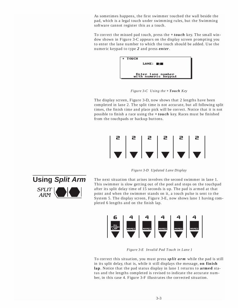
The next situation that arises involves the second swimmer in lane 1.This swimmer is slow getting out of the pool and steps on the touchpadafter its split delay time of 15 seconds is up. The pad is armed at thatpoint and when the swimmer stands on it, a touch pulse is sent to theSystem 5. The display screen, Figure 3-E, now shows lane 1 having com-pleted 6 lengths and on the finish lap.
Figure 3-E Invalid Pad Touch in Lane 1
To correct this situation, you must press split arm while the pad is stillin its split delay, that is, while it still displays the message, on finishlap. Notice that the pad status display in lane 1 returns to armed sta-tus and the lengths completed is revised to indicate the accurate num-ber, in this case 4. Figure 3-F illustrates the corrected situation.
3-3

Using Finish Arm
Figure 3-F Lane 1 Reset to 4 Lengths Completed
All swimmers touch at the end of the third leg of this race and the finalleg swimmers are in the pool. As the swimmers turn at the far end ofthe pool, you notice that lane 5 did not register a pad touch. Its lengthcount shows 4, its pad display is not F Armed and the warning messageLength is flashing over the lane indicator. Figure 3-G illustrates thissituation.
Figure 3-G Lane 5 Pad Touch Missed
To prepare the lane for the upcoming finish touch, press the finisharm key in lane 5. The length counter now displays 6 and the pad sta-tus display indicates that the pad is F Armed, as shown in Figure 3-H.The final split time is not accurate, but as demonstrated with the padtouch missed earlier in the race, the finish time and place pick will beaccurate.
Figure 3-H Updated Lane Display
All swimmers touch their pads successfully at the finish. The System 5beeps as each swimmer finishes and displays the place picks in high-lighted numbers above each lane as shown in Figure 3-I. As soon as therace is over, press the store/print key. As its name indicates, this keystores the race results in memory. A message appears on the displayscreen confirming that the results have been stored and printing ofresults begins immediately. If your printer does not respond within 1second of pressing the store/print key, make sure it is turned on andthat it is on-line. Notice when timing races, in print-in or title eventmode that the event and heat numbers are printed on the resultsprintout.
3-4
Finishing The Race

Figure 3-I Display at the End of the Race
Finally, press reset to prepare for the next race. After pressing reset,you can enter the race distance, event and heat numbers for the nextrace. Any other sequence of entering race data may not produce theresults intended.
3-5

3-6

Self-Test/LoadingSwimming
Summary
Operation
This chapter describes in detail the operation of the System 5 SportsTimer and Swimming software, the function of each key on theSwimming keyboard insert and all softkey functions.
This chapter is not meant to be read from beginning to end. It isdesigned to be used as a reference for specific features and functions ofthe Swimming software. When used in conjunction with the index at theend of this manual, this chapter provides quick access to specific,detailed information.
While it is not necessary to read the entire chapter, quickly skimmingthe first 18 pages will provide you with a good overview of the operationof the Swimming software, the function of the keyboard and the mean-ing of various items appearing on the display screen. More informationon using the Swimming software appears in Chapter 3 which includes acomplete race tutorial.
This section describes the basic operation of the System 5 Sports Timerand Swimming software. The different modes of operation and a basicexplanation of the behavior of the timing system are included.
The Self-Test screen is the first screen you see when you turn on yourSystem 5. After the self-test is complete, you can load any of the sportsprograms installed on your System 5.
When you turn on your System 5 it performs a series of self-tests. If anyof these tests fail, the Test/Programming menu is displayed along withan indication of which test failed. Follow the instructions on the screento conduct further tests and troubleshooting. Refer to Appendix B forcomplete instructions on using the Test/Programming menu. If a testfails after you have tried all the recommended remedies, call ColoradoTime Systems' Customer Service Department at 800-287-0653 (U.S. andCanada) or (970)667-1000 (international).
Figure 4-A System 5 Sports Menu
4-1
4
Reference
Basic Operation

User InterfaceSummary
Operation
Warning MessagesSummary
OperationPad
Length
Timing Problems
After the self-tests are completed, the Sports Menu appears. The SportsMenu displays the sports software available from Colorado TimeSystems and the sports programs currently installed in your System 5.Press the Swimming/Diving softkey. Swimming loads and is ready touse in write-in mode.
The System 5 Sports Timer/Swimming software user interface consistsof a full-size Liquid Crystal Display(LCD) and a membrane keyboardwith removable insert.
The Swimming program uses the LCD screen to communicate a widerange of information to you. The status of the current race is displayedat all times. Other important information displayed includes the run-ning time, the race number, whether the timer has been reset,event and heat numbers, the current operating mode, race distanceand type, lane status, battery level, and softkey functions avail-able. The locations of all these displayed items are indicated on the dis-play example, Figure 4-B.
4-B. Figure 4-B Swimming Display Screen
A. Running Time Display G. Place at Finish M. Pad Armed: Finish/SplitB. Battery Life Gauges H. Mode of Operation N. Pad Shorted WarningC. Softkeys I. Stored Race Information O. Pad Inactive After TouchD. Race #, Event, Heat J. Warning Message (On Finish Lap)E. Race Description K. Power Source in UseF. Lane Disqualification L. Lengths Completed
Two important warning messages can appear on the display screen,indicating a potential timing problem.
This message flashes continuously in the lane display whenever thetouchpad in that lane is closed. If no one is standing on the touchpad,this may indicate a shorted touchpad.
When this message flashes in the lane display, it indicates thatSwimming is expecting a pad touch in that lane. This message continuesto flash until either a pad touch is received or you press +touch to adda missed pad hit.
If timing problems are encountered during a race, such as touchpad andbackup button times that do not compare properly, the screen shown inFigure 4-C is displayed when you press store/print. Carefully check theresult(s) displayed in the highlighted lane(s). To use the backup timefor a problem lane, press the softkey labeled Use_lnX Backup with "X"replaced by the specific lane number as shown in Figure 4-B. Press theEdit/DQ softkey to edit the time(s) in question. Refer to the description
4-2

Modes of OperationSummary
Operation
Write-in Mode
Print-in Mode
Title Mode
of the Edit/DQ key later in this chapter for complete instructions.When you are satisfied that the results are accurate, press the OK toPrint softkey to store the results and continue the meet.
Figure 4-C Timing Problems Display and Softkey Menu
Your Swimming software provides three methods of keeping track ofrace information. Each method has advantages and is suited to certaintypes of meets and operator experience levels. Write-in mode requiresyou to keep track of all race-type information. Print-in mode promptsyou to enter the event and heat numbers which are printed on the dis-play screen and on the race printout. Title mode, with a programmedevent sequence, automatically updates all race information when youpress the next event key
When you first load the Swimming software, it is ready to operate inwrite-in mode. You must enter race distance manually from the key-board. The event and heat numbers, even if entered on the displayscreen, are not printed on the race printout, nor are they stored inmemory. You must write in the event and heat numbers on the raceprintout. All other race timing functions operate as usual.
Some reasons to use write-in mode: Write-in mode is well suited to the inexperienced timer operator.Simply turn on the System 5 and enter race distance to begin timing.When the race is done, write in the heat and event numbers on the raceprintout. When not in using meet management software or posting raceresults, write-in mode is completely adequate.
Print in mode prompts you to enter unique event and heat numbersbefore each race. You must also set the race distance manually from thekeyboard. Print-in mode prints the event and heat numbers on therace printout and stores them in memory. If at the start of the race, theevent and heat numbers duplicate those of a stored race in the samemeet, the event and heat display flashes you to remind you to enterunique event and heat numbers. The event and heat numbers must beunique for the current meet in order to avoid confusion when tabulatingresults.
Some reasons to use print-in mode:Print-in mode requires a more experienced timer operator. It producesvery professional looking race printouts and allows you to recall heatand event printouts from memory.
Title mode is most useful when you have programmed an event
4-3

Timing CorrectionsSummary
Operation
sequence in Setups. When you press next event, the race distance anddescription change to match the information you entered for that racein the event sequence. All race information is printed on race printouts.You do not need to write anything on the printouts. To change the racedescription, press any race distance key and build the new race descrip-tion by pressing the appropriate softkeys. Press enter when done. Thenew race information appears on the race printout, but the programmedevent sequence is not altered. Refer to Setups for event sequence pro-gramming instructions.
You can take advantage of title mode's versatility without a pro-grammed event sequence. To set the race distance and description, pressany race distance key. The prompt box allows you to enter the racedescription. Press the softkeys corresponding to the appropriate racetype and press enter when the description is complete. All informationentered appears on the race printout and is stored in memory.
Some reasons to use title mode:Title mode requires an experienced timer operator familiar with theprocess of programming an event sequence., but once the meet begins,this mode is easiest to use. Simply pressing next event updates all raceinformation. Races can be run in rapid succession without stressing thetimer operator.
The Swimming software is designed to correct timing inaccuracies intro-duced when automatic and manual timing methods are combined.
A start is considered manual when a person presses the start button tostart the timer when the strobe flashes or the starting gun or hornsounds. In this case, human reaction time is a factor. If the same personfires the starting gun or strobe light and presses the start button, thereis no human reaction time to compensate for. This last start type isessentially an automatic start. Keep this distinction in mind when con-figuring the Swimming software.
A start is considered automatic is the start systems sends an electronicpulse to the System 5 at the start of the race. A loudspeaker start sys-tem (e.g. model INFINITY) is an example of an automatic start system.
If you are using manual start and touchpad finish, or automatic startand button finish, Swimming compensates for the timing discrepancyincurred by human reaction time. Manual starts are corrected by adding0.15 seconds to the recorded start time. Manual finishes are correctedby subtracting 0.15 seconds from the recorded time.
The 0.15 second human factor has been determined to be the statisticalmedian delay incurred by manual start and finish timing . When bothstart and finish are manually determined, no correction factor isrequired because the late start is compensated for by the late finish ascompared to actual time. For a complete discussion of swim timing andthe statistical data and methods used to arrive at the standard correc-tion factor, refer to J. Killpatrick, Timing Accuracies for Swimming (1975 J. Killpatrick, Minneapolis, MN) and Timing and JudgingAccuracies for Swimming ( 1976 J. Killpatrick, Minneapolis, MN).
Refer to Start under Setups in this chapter for complete information onconfiguring the Swimming software for your start system.
4-4

Relay Judging
Automatic RelayJudging
Relay judging is a built-in Swimming feature. Relay judging is accom-plished automatically using model RJP relay judging platforms for eachlane.
To use Swimming's automatic relay judging feature, you must firstinstall and connect one model RJP for each lane. Refer to your RJPInstallation Guide for complete installation instructions. Refer to Figure2-G in chapter 2 for a full system diagram. After the relay judging plat-forms are installed and cabled, enable relay judging in the Swimmingsoftware by following these steps.
1) Press the Setups softkey. Press the Up or Down softkey until theselected setup is Printer as shown in Figure 4-D.
2) Press 3 on the numeric keypad to select Store/Print Format.
Figure 4-D Printer Setups Window
3) Press the Left or Right softkey to position the cursor at the point inthe printout sequence where you want the relay information to appear.press the Up or Down softkey until the selected item is RelayJudging Exchanges. Press enter. Repeat the process to select RelayExchange Summary. The completed setup is shown in Figure 4-E.
Figure 4-E Store/Print Format
4) Press quit, and then press the Record Setups and Yes softkeys tosave the new print setup. Press quit to exit Setups.
Refer to the Setups section in this chapter for complete information onSwimming setups.
4-5

Summary
Lane On-Off
Function
Operation
Finish ArmFunction
Operation
Split ArmFunction
Operation
This section describes the action of the keys on the Swimming keyboardinsert. The keys are described in order as they appear from left to righton the keyboard. Refer to the Index at the end of this manual to locate aspecific key description quickly. References to keyboard keys appearlower case bold italic type in this manual.
Figure 4-F Swimming Keyboard Insert
The lane on-off keys are located directly under the lane numbers onthe Swimming keyboard. These keys toggle output to the scoreboardand display screen from each lane on or off depending on current sta-tus.
If lane 10 is currently off, pressing the on-off key for lane 10 will tunethe lane on. Data are still collected from a lane when it is turned off,including running time, splits and finish time. The data collected arenot sent to the scoreboard unless the lane is turned on. When a lane isturned off, its number and its status are not displayed on the Swimmingscreen.
Press finish arm to arm the touchpad in the selected lane for a finishtouch. Use this key to arm a lane for a finish touch when the swimmermissed a split touch.
When you press this key, the Swimming display changes the lane statusto waiting for a finish touch. The display also updates the number oflengths to indicate the final lap. If pressed by mistake, you must pressthe -touch key to return the lane to its prior state.
This key allows you to rearm a touchpad for a split touch after aninvalid touch has occurred.
For example, in a relay race, the relay swimmer stands on the padbefore taking his or her mark. The pad registers a touch that is invalid.To rearm the pad for the proper split touch before the swimmer in thepool touches, press split arm immediately after the invalid pad touch,
4-6
Keyboard

StartFunction
Operation
Store/PrintFunction
Operation
Next HeatFunction
Operation
Next EventFunction
Operation
during the pad split delay time. After a touch, the pad remains inactivefor a user-definable period, normally 15 seconds.
This key is used as the final backup start in case the primary andsecondary systems fail.
Do not press this key before the primary start system has sounded(horn, start pistol transducer, etc.) The start key also allows the timingoperator to start swimmers when no other start system is used.
Stores the results of the race just completed in memory and prints theresults. Indicates that the race is over.
Press this key at the end of each race to tell the Swimming softwarethat the race is completed. The results of the current race are stored inmemory and printed according to the print setup.
If you press this key before all lanes have finished, or if a swimmermissed a finish touch, the display screen informs you that not all laneshave received a finish touch, If there was no swimmer in an unfinishedlane, turn that lane off and press store/print. If there was a swimmerin an unfinished lane, turn that lane off, press store/print and thenenter the last split or backup time for that lane using the edit/DQ key.
If a timing problem occurs, a window appears on the display screen asindicated on page 4-3 which indicates the problem lane(s). The lane(s) inquestion is displayed in reverse video. Press edit/DQ to edit the time ina highlighted lane. Enter the lane number and select the correct timefrom the softkey menu or enter a stopwatch time with the numeric key-pad. Refer to Setups to select the kinds of timing discrepancies theSwimming software is to check.
Advances the Heat counter by one (1).
Press this key before starting the next heat of an event. The heat num-ber displayed on the screen advances by one (1). The heat number isonly stored and printed when the Swimming software is operated inprint-in or title mode.
Advances Event counter by one (1). When operating the Swimming soft-ware in title mode with a programmed event sequence, the race descrip-tion corresponding to the new event number is automatically displayed.
Press this key before starting the next event on the meet schedule. Theevent number displayed on the screen advances by one (1). The eventnumber is only printed when the Swimming software is operated inprint-in or title mode. When using title mode with a programmedevent sequence, the race distance and type are displayed on the screen.In write-in mode, you are neither required or reminded to update theevent number. The event number is neither printed nor stored in memo-
4-7

Edit Event/Heat
Function
Operation
Event ModeFunction
Operation
Edit/DQFunction
Operation
+TouchFunction
Operation
Note:
ry when operating in write-in mode. Be sure to set the correct race dis-tance before starting the next race.
This key allows you to edit the currently displayed event and heat num-bers.
Press this key, type the desired event number with the numeric keypadand press enter. Then type the desired heat number and press enter. Ifthe last stored race was a false start, press the softkey labeled FalseStart and confirm the false start by pressing the softkey labeled Yes.The current race is invalidated in memory, allowing you to maintainunique event and heat numbers.
This key allows you to select the mode of operation.
Press this key to display the modes of operation softkey menu. Selectone of the three modes available. Refer to the discussion of modes ofoperation earlier in this chapter for details.
Allows you to edit times or disqualify swimmers from the last storedrace.
This key is only valid after pressing the store/print or reset. To edittimes, press this key and then press the Edit Time softkey. Type thelane number you want to edit and press enter. The window on thescreen displays the lane number and the recorded time. The softkeysdisplay the backup times and the last recorded split time. The top soft-key is labeled with the median time for 3-button backup systems or withthe average for 2-button backup systems. Press the softkey correspond-ing to the time you want to attach to that lane or press c/e and type thestopwatch time. Press enter when done. The Swimming software calcu-lates any changes in finish order based on the new time.
To disqualify a swimmer from the last stored race, press edit/DQ andthen press the DQ softkey. Type the lane number to DQ using thenumeric keypad and press enter to disqualify the swimmer in that lane.Repeat the procedure to un-DQ a disqualified swimmer.
This key allows you to add a pad touch when the swimmer in a givenlane missed a touch.
To add a pad touch to a selected lane, press this key, type the lane num-ber using the numeric keypad and press enter. The display is immedi-ately updated to indicate the added touch
A race cannot be finished from the keyboard. Therefore, this key is invalidon the finish lap.
4-8

-TouchFunction
Operation
Events
Function
Operation
ResetFunction
Operation
This key allows you to subtract a pad touch from the total in a givenlane. Used when an invalid pad touch is recorded. For example, when aswimmer on the pool deck steps on the lip of a touchpad, triggering aninvalid touch.
To remove a pad touch from a selected lane, press this key, type the lanenumber using the numeric keypad and press enter. The display screenis immediately updates to reflect the removed touch.
These keys allow you to enter the race distance.
Use the numbered keys in this category to set the race distance, eitherin yards or meters as defined in Setups. Press the key corresponding tothe distance desired. The race distance displayed changes to match thenew distance and the race status display is updated. Press more eventsto display more event lengths in yards or meters on the softkey menuthen press the softkey next to the desired race distance.
This key clears the Swimming display and prepares it for the start ofthe next race.
The reset key is composed of two keys placed side-by-side. Both keysmust be pressed simultaneously to reset the Swimming race display.Pressing these keys indicates that the race is over. The display is clearedand ready for the start of the next race. Do not press reset during avalid race.
Whenever you press reset, the race is over even if a swimmer has notfinished. The race is stored showing results only for the lanes that werefinished before reset was pressed.
If you press reset within 10 seconds of a start, the Swimming softwareassumes that there was a false start and no data is stored.
4-9

Function
Operation
EnterFunction
Operation
C/EFunction
Operation
This key allows you to enter numbers in response to a variety ofprompts. The numeric keypad is located to the right of the keyboardinsert on the System 5 lower console.
There are many instances during the operation of the Swimming soft-ware when it is necessary to enter numbers. Whenever a numeric entryis required, use the keypad to make the desired entry.
This key enters the numeric or other keyboard enter into the Swimmingsoftware.
After a keyboard entry, press enter to accept the entry.
This key allows you to clear an existing entry or clear an entry made inerror.
Press c/e to clear all data from a prompt line on the screen.
The console keys are located to the right of the LCD screen. The consolekeys are shown in Figure 4-G
Figure 4-G Console Keys
4-10
Numeric Keypad
Console Keys

EnterFunction
Operation
QuitFunction
Operation
Battery CheckFunction
Operation
Caution:
HelpFunction
Operation
This key enters a numeric or other keyboard entry into the Swimmingsoftware.
After typing information on the keyboard or numeric keypad, pressenter to accept the data. This key functions exactly the same as theenter key on the numeric keypad.
This key allows you to leave a function without saving data entered orto exit the current prompt when enter does not do so.
Press this key to exit a prompt after information has been entered. Thiskey also allows you to cancel an operation that requires an entry with-out changing the current settings. No information is entered if youpress quit before pressing enter.
This key displays the estimated operating time of the batteries in yourSystem 5.
Press this key to display the graphic battery life gauge for the batteries.The power source currently in use is also displayed. The battery liferemaining at present and maximum load is approximate. A low readingon this gauge indicates that the batteries must be replaced. Use onlyalkaline batteries to obtain the most accurate battery gauge indications.
If the Present Load gauge reads two (2) hours or less, replace the batter-ies at the first opportunity. Do not take a chance on losing the time for arace should the batteries go completely dead.
Your Swimming software included context sensitive help informationwhich is available at any time.
Press this key to display useful information on the screen. The help textcovers the currently active operation. Use help as a reminder for usinga Swimming feature not as a replacement for this manual. The informa-tion available in help is not intended to replace the manual.
4-11

Summary
Operation
PrintSummary
Operation
This section describes the operation of the Swimming softkeys. The soft-keys are the column of six unlabeled keys immediately to the right ofthe display screen. The function of each key changes depending on theoption selected. The screen displays the function currently availabledirectly to the left of each softkey. If no label appears next to the softkey,that key is inactive. In this manual, softkey names appear capitalizedand in Bold-Italic type. See figure 4-H for an example of the main soft-key menu.
Figure 4-H Main Softkey Menu
Each softkey's functions are organized in layers or levels. The first levelconsists of the six softkeys displayed when you first load Swimming soft-ware. When you press one of these softkeys, a second level providingmore specific choices is displayed. In general, pressing a second levelsoftkey executes an action or prompts you for entry of data.
If you press a softkey by mistake, or want to return to race timing modewhen done using a softkey, press quit. If you have not pressed enterafter making an entry, pressing quit exits without saving that entry.
The Print softkey allows you to print additional printouts from the laststored race organized in a variety of ways. Each item is printed in theorder in which you press the softkeys. Make sure your printer is on-lineand loaded with paper before beginning. Print samples appear later inthis chapter.
After pressing store/print, press the Print softkey to access the printmenus. The softkeys that make up the first print menu are shown inFigure 4-I. You may press any combination of keys available. Printingbegins immediately.
4-12
Softkeys

By LaneFunction
By PlaceFunction
Race SummaryFunction
Splits/SummaryFunction
Relay SummaryFunction
MoreFunction
Operation
Figure 4-I Print Softkey Menu 1
Prints an additional copy of race results stored by lane.
Prints an additional copy of race results stored by place.
Prints an additional copy of results sorted by lane and by place.
Prints the splits from the last stored race.
Prints a summary of the relay exchanges from the last stored race.
Toggles between the two Print softkey menus.
Press this softkey to display the other Print softkey menu. The secondPrint softkey menu is shown in Figure 4-J.
Figure 4-J Print Softkey Menu 2
4-13

W/Names By LaneFunction
W/Names By PlaceFunction
Sponsor’s MessageFunction
Top Of FormFunction
Form FeedFunction
Operation
More
DisplaySummary
Operation
Prints an additional copy of race results sorted by lane with a line foryou to write in the swimmers' name.
Prints an additional copy of race results sorted by place with a line foryou to write in the swimmers' names.
Prints the Sponsor's Message on the race printout. Refer to Setups forinstructions on building a sponsor's message.
Press this softkey when you have reset the paper in your printer to thetop of a new page. Swimming 5 needs to know that the printer is set atthe top of a new page to keep the printouts properly organized.
Advances the paper to the top of the next page. Provides page breaksbetween pages of race information.
Press this softkey at the point in the print sequence where you want toend a page. Any information printed after a form feed begins at the topof the next page.
Press this softkey to display the other Print softkey menu.
The Display softkey provides access to features that are displayed onthe Swimming display screen. The Display softkey menu is shown inFigure 4-L.
Press this softkey to display race information on-screen including thelast split or finish time for each active lane, the place or last length com-pleted, the backup buttons pressed and early relay exchanges as shownin Figure 4-K. Backup times are not displayed in this window.
Figure 4-K Lane Information Display Window
4-14

Time Of DayFunction
Operation
Display LanesFunction
Operation
Warning Messages On/OffFunction
Software VersionFunction
ScoreboardSummary
Operation
Figure 4-L Display Softkey Menu
Displays the time, day and date from the System 5's internal clock.
Press this softkey to display the time, day and date. Refer to Setups sec-tion later in this chapter for instructions on setting the time, day anddate.
Displays current race information on-screen including the last split orfinish time for each active lane, the place or last length completed, thebackup buttons pressed and early relay exchanges are shown in Figure4-K. Backup times are not displayed in this window.
Press this softkey to display current race information on-screen.
Toggles the warning messages that flash above the lane displays on oroff for the current race. These warnings, including Length, aredescribed earlier in this chapter.
Displays the version of the Swimming 5 software currently loaded andthe version of firmware installed in your System 5 Sports Timer.
This softkey provides access to special scoreboard control and displayfeatures.
Press this softkey to display the Scoreboard softkey menu.
Figure 4-M Scoreboard Softkey Menu
4-15

Step DataFunction
Clear LanesFunction
Operation
Scorebrd BlankFunction
Operation
Scorebrd OnFunction
Operation
Note:
Team ScoresFunction
Operation
Sequences again through the results of the last race. This key is activeonly if you are using a single-line scoreboard.
Clears the place and time area on each lane module. The next startreturns the scoreboard to normal display status.
Press this softkey to clear the time and place from all active lanes onmulti-line scoreboards. The lane number display is not cleared. Thisallows you to edit time and place in the event of an invalid pad hit, etc.Pressing Scbd On or the next start returns the scoreboard to normaldisplay status.
Pressed once, this softkey blanks the scoreboard and displays the time-of-day. Pressed twice in a row, this key blanks the entire score-board.
Press this softkey to blank the scoreboard and display the time-of-day.Press again immediately to blank all lines of the scoreboard. The entirescoreboard should be blanked when turning off the System 5. Press theScorebrd On softkey to return the scoreboard to normal display status.
Returns the scoreboard to normal display status.
Press this softkey to return the scoreboard to normal display statusafter pressing the Clear Lanes or Scorebrd Blank softkeys
If you have selected the Three-, Four-, or Five-Line Scoreboard option inScoreboard Setups, this softkey changes to Scorebrd On/Blank, combin-ing the features of these two softkeys. The second softkey on theScoreboard softkey menu now allows you to display race results for thealternate set of lanes.
Allows entry of up to four teams' scores to display point totals on thescoreboard.
Press the softkey labeled with the appropriate team type and enter thecurrent score. Teams available are Home, Guest 1, Guest 2 and Guest 3.You must keep track of team scores manually. Type the appropriatescore(s) as shown in Figure 4-N and press enter. The team scores areimmediately displayed on the scoreboard. Press quit instead of enteronly if you do not want to display new team scores.
Figure 4-N Team Scores Prompt
4-16

Record TimeFunction
Operation
SetupsSummary
Setups Softkey MenuSummary
StartFunction
Allows entry of the record time for the event.
Figure 4-O Record Time Prompt
Press this softkey, type the record time for the current event using thenumeric keypad as shown in Figure 4-O, and press enter. The timeentered is displayed on the optional Record Time scoreboard module(0B). Press quit to exit without displaying a new record time.
The Setups softkey provides access to features that allow you to cus-tomize the Swimming software. With the exception of Time/Date, setupchanges are made permanent only if you press the Record Setups soft-key after making changes. Otherwise, setup changes apply to the cur-rent session only and are lost when you turn off your System 5. Noticethe race information displayed in condensed form at the bottom of thedisplay screen. Pressing Setups does not interfere with race timing, butas a general rule, setup changes should only be made when theSwimming software is in reset state. Press quit to leave Setups.
The three softkeys shown in Figure 4-P are active from the main Setupsdisplay screen. Press the Up or Down softkey to move the arrow point-er to the desired setup option. If you want setup changes to be perma-nent, press the Record Setups softkey and then press the Yes softkeyto save. Use the numeric keypad to select a specific setup option.
Figure 4-P Setups Softkey Menu
There are three ways to start the Swimming 5 race timer. The mostaccurate method is to use an automatic (electronic) electronic start sys-
4-17

Operation
Note:
Finish/ButtonsFunction
Operation
Note:
tem such as a horn start or start pistol transducer. Manual button startis much less accurate. Refer to the discussion of Timing Corrections inthis chapter for more information. The final start method, which shouldonly be used if all other start systems fail, is to press the start key onthe Swimming keyboard.
Figure 4-Q Start Setups Window
Press 1 to select automatic start as the primary start method. Press 2to select a manual start button as the primary start method.
The Start setups affect automatic adjustments. If not set to agree with yourhardware configuration, inaccurate race timing could result.
This feature allows you to configure finish parameters to match yourhardware setup. The Swimming system uses either touchpads or but-tons for primary finish. The times produced by touchpad finish areextremely accurate. Alternatively, each lane can have up to three finishbuttons. If three buttons are used, the finish time is the median of thethree. If two two buttons are used, the finish time is the average of thetwo. Button finish times are less accurate because of human reactiontime. Refer to the discussion of Timing Corrections earlier in this chap-ter for more information on human reaction time.
Figure 4-R Finish/Buttons Window
If touchpads are the primary finish system, up to three buttons per lanecan be used to provide backup finish times. If you select option 8,Swimming 5 alerts you when the backup buttons are pushed more than0.3 seconds before the pad touch. Option 9 alerts you when the backupand pad times are not within 0.3 seconds of each other.
Options 1-4 allow you to select the prime finish type. If you selectoptions 2, 3 or 4, press 0 to select the input for the selected buttonprime finish. Options 5-7 let you set the number of backup buttons youare using. Option 8 alerts you on the race printout is a backup button ispressed before the pad is touched. Option 9 compares the pad and back-up button times. Note that pad must be selected as the prime finishtype to use automatic time comparison.
Any setup changes you make are stored in permanent memory only if you
4-18

Hardware SetupFunction
Operation
SplitsFunction
Operation
press the Record Setups softkey and then press the Yes softkey to save.If you do not press Record Setups, setup changes are lost when you turnoff your System 5.
Allows you to configure your System 5 internal speaker volume,Swimming touchpad voltage, whether or not to allow Setup informationto be downloaded from a PC and allows you to select the relay judgingmethod. The speaker volume should be set to an audible level. Thetouchpad voltage can be lowered to help fight pad connector corrosion.Running a swim meet with I/O voltage set to low may help reduce cor-rosion, but if you touchpad/backup button cable is long, for example, donot use this option.
Figure 4-S Hardware Setup Window
It is very important that you set the proper relay judging method. If youselect Relay Judging Using Buttons, Swimming 5 compensates forhuman reaction time by subtracting 0.15 seconds from the button judg-ing time. No timing correction is applied to relay judging platform.
Press 1 to set the System 5 internal speaker volume. Type 0 to turn thespeaker off, 1 for low volume, 2 for medium volume or 3 for highest vol-ume in the prompt box and press enter. Press 2 to select low voltagedelivered to the touchpads. Press 3 to enable the Allow Remote Setupoption. When enabled, this option allows you to edit all setup informa-tion on a PC using meet management software and then upload thatinformation to your System 5 through com port 1. This is especially use-ful for setting up event sequences. Press 4 to select relay judging usingeither Buttons or Platforms.
Controls split printing format. Splits printed by lap produce the runningtime of the lap just completed only. Cumulative splits print the totalrunning time of the race to that point.
Figure 4-T Splits Setup Window
Press 1 to print cumulative splits, or press 2 to print splits by lap. Youcan select both options.
4-19

TimingFunction
Operation
Note:
PoolFunction
Controls variable timing functions. The timing accuracy option selectsthe number of decimal places to which results are printed. Pad splitdelay time allows you to set the length of time the touchpads are inoper-ative after a touch, allowing relay swimmers to get out to of the poolwithout triggering a pad touch. The recommended delay time for bothnear- and far-end pads is 15 seconds. When time warning messages areenabled, the Swimming software predicts how long a swimmer shouldtake to complete a lap based on the previous lap's time. If the predictedlap time is exceeded, the Swimming software assumes that the swimmermissed a pad touch and posts a warning message on the display screen.You can then press +touch to update the race information if a padtouch was indeed missed. If the swimmers in a meet are erratic in theirlap times, disable this function to cancel the warning message. The paddelay at start time allows you to set the time all pads are inoperativeafter the start of a race. The last two options allow you to set the score-board or System 5 screen to count down the number of lengths in arace.
Figure 4-U Timing Setups Window
Press 1 or 2 to set the timing accuracy to .01 seconds or .001 secondsrespectively. Options 3 and 4 allow you to set the pad split delay time.Use the numeric keypad to type a new delay time and press enter.Option 5 toggles the time warning messages on and off. Press 6 to setthe pad delay at start time . Use the numeric keypad to type a new delaytime and press enter. Options 7 and 8 set length count down mode forthe scoreboard and System 5 screen.
Any setup changes you make are stored in permanent memory only if youpress the Record Setups softkey and then press the Yes softkey to save.If you do not press Record Setups , setup changes are lost when youturn off your System 5.
Controls the setup configuration information for your pool. In mostinstallations, the touchpad/backup button cables are set up with lane 1closest to the timer. If, however, lane 1 is at the far end of the cable,reverse the lane order with this setup to properly configure theSwimming software. If you have touchpads installed at the far end ofthe pool, enable far-end splits. Notice that if you enable far-end splitsand set the race distance to 1 length, the finish touch comes from thefar-end touchpad. If far-end splits are disabled, a 1-length race mustfinish at the near-end touchpads. This setup also allows you to enter thenumber of lanes in the pool, either 6,8 or 10.
Proper timer configuration requires that you enter the pool length onthis setup. For example, a 100 yard race in a 25 yard pool is 4 lengths,or 2 pad touches at the near end. A 100 meter race in a 50 meter pool is
4-20

Operation
ScoreboardFunction
2 lengths, or one touch at the near end to finish. Indicate also the unitof measurement, either yards or meters.
Figure 4-V Pool Setups Window
• Press 1 to select normal lane order-lane 1 nearest the timer. • Press 2 to reverse the order of the lanes. • Press 3, type the number of lanes in the pool with the numeric keypad
and press enter. Only 6, 8 and 10 lanes are valid. • Press 4 to enable touchpads at both ends of the pool. • Press 5 to indicate that the pool is 25 yards or meters in length. • Press 6 to indicate that the pool is 50 yards or meters.• Press 7 to indicate that the pool's length is measured in yards.• Press 8 to indicate that the pool's length is measured in meters.
Controls the parameters that affect your scoreboard. The data transmis-sion rate must be matched to the communication rate of your score-board. Set either at high(9600 baud) or low at (2400 baud) speed. Seeyour scoreboard manual for the communication rate of your scoreboard.Figure 4-W shows a sample Scoreboard Setup display window.
Self-tests checks all scoreboard digit segments by running a test patternon the scoreboard for 1 minute. The blank scoreboard module featureallows you to blank unused scoreboard modules.
Scoreboard Setups also allow you to define scoreboard modules.Scoreboard module definition is a complex operation whichshould not be attempted by an inexperienced operator. Carefullyread the Scoreboard section in chapter 2 before attempting to redefineany scoreboard modules. In the Swimming software all scoreboard mod-ule logical addresses default to the physical addresses. For example, thephysical of the scoreboard module displaying data for lane 1 is 01, so thelogical address is also 01. If you want the lane 1 (01) scoreboard moduleto display line 10's data set its logical address in this setup to 0A. On themodule definition window, as shown in Figure 4-X, the physical address-es appear on the left, the redefined logical addresses on the right.
Figure 4-W Scoreboard Setups Window
Option 5 allows you to display results from two lanes on one scoreboardline. The number of scoreboard lines available for this option is equal to
4-21

Operation
Note:
half the number of active lanes in your pool. For example, if you have a10-lane pool, this option allows you to display all race results on a 5-linescoreboard. At the end of a race, your scoreboard automatically displaysthe results for lane 1 through 5. To display lanes 6 through 10, press theScoreboard softkey and then the Display 6-10 softkey.
Options 6, 7 and 8 apply only to single-line scoreboards. Ordinarily, asingle-line scoreboard displays the race results by place at the end of therace and then displays the programmed sequence. This feature allowsyou to set the number of times this information is displayed. Thesequence time for each item also applies to the single-line scoreboard.
Select the time in seconds each item in the sequence is displayed. Thissetup also sets the minimum time that each result is displayed as theswimmers finish.
Options 9 and 0 allow you to choose the way race results sent to thescoreboard are sorted, either by lane order or by place order.
Press 1 to toggle between high speed-9600 baud and low speed-2400baud. See your scoreboard manual for communication rate of yourscoreboard.
Press 2 to self-test scoreboard modules. Press 3 to display or changescoreboard module definitions, press the Up or Down softkey until thearrow points at the desired physical address as shown in Figure 4-X,then press 1 and type the two-digit logical address in the prompt boxwith the numeric keypad (and with the softkey menu if a letter isrequired, as in 0A). Press 2 to display module definitions on the score-board. Press 2 again to clear definitions on the scoreboard.
Figure 4-X Scoreboard Module Definition Window
Scoreboard module numbers and sample displays appear in Chapter 2.
Press 4 to select Blank Module(s). Press the Up or Down softkeyuntil the arrow points at the desired module and press 1 to blank, asshown in Figure 4-Y. Repeat the procedure to un-blank a blanked mod-ule.
Figure 4-Y Blank Scoreboard Module Window
Press 5 to display the results from two lanes on one scoreboard line.The number of scoreboard lines available for this option is equal to half
4-22

Note:
PrinterFunction
the number of active lanes in your pool. For example, if you have a 10-lane pool, this options allows you to display all race results on a 5-linescoreboard. At the end of a race, your scoreboard automatically displaysthe results for lanes 1 through 5. To display lines 6 through 10, pressthe Scoreboard softkey and then the Display 6-10 softkey.
Press 6 to enter the number of times a single-line scoreboard is to stepthrough the results of the last race--type the desired number and pressenter. Press 7 to display the single-line scoreboard sequence timeprompt box. Type the time in seconds that each item is to be displayedon a single-line scoreboard and press enter.
Press 8 to define a single-line scoreboard sequence list, as shown inFigure 4-Z. Choose items to be added to the default by place sequenceon a single-line scoreboard. Press the Up or Down softkey until thearrow points at the desired item and press enter to add the selection tothe list. Press quit to exit this window.
Figure 4-Z Single-Line Scoreboard Sequence Window
Press 9 to display race results on the scoreboard in lane, place and timeorder. This is the typical sequence at U.S. pools. The signage on thescoreboard must be placed as shown on page 2-8 for results sorted bylane (LN, PL, TIME).
Press 0 to display race results on the scoreboard in place, lane and timeorder. This is the typical sequence at European pools where place orderis more popular than lane order. Note that the signage on the score-board must be placed in place, lane and time order (PL, LN, TIME).
Refer to Figure 4-W on page 4-21 for an example of the main Scoreboardsetups screen.
Any setup changes you make are stored in permanent memory only if youpress the Record Setups softkey and then press the Yes softkey to save.If you do not press Record Setups , setup changes are lost when youturn off your System 5.
The Swimming system can use any printer that has a standard parallelinterface and can print a minimum of 80 characters per line. Printersetups include the standard definitions for printers listed in the scrollbox. Be sure to select the printer you have from the list of printers inthe default printer scroll box. If your printer is not listed, you mustselect the user defined printer and enter the printer control codes forpica, elite and condensed print as listed in your printer's manual.
4-23

Operation
Figure 4-AA Printer Setups Display Window
This setup also allows you to customize the sequence of informationprinted when you press store/print. One of the items you can print oneach page of the race printout is a sponsor's message. Enter yourschool's name, meet name, team name or a sponsor's advertising mes-sage. One line of print is available for your sponsor's message.
You can also print the setups that affect race timing, including type offinish, backup compare options, etc. using the Print Setups softkey.The last four options on this setup menu allow you to set the pagelength for your printer and select the number of characters per inch(CPI) you want on your race printouts. Pica type prints 10 CPI, eliteprints 12 CPI and condensed 17 CPI. It is best to use the largest typesize possible for the number of lanes in use. For 6-lane pools, select picatype. For 8-lane pools, select elite type and for 10-lane pools, select con-densed type. If your printout is not properly formatted, with type wrap-ping from the previous line to the next line, select the next smaller typesize. You can select 8 lines of type per inch for use with condensed type.The last option on this setup allows you to have Swimming print raceresults immediately when you press store/print even if there are timingproblems. You can then mark the corrections on the printout. Refer topage 4-4 for more information on timing problems.
Press 1 to select your printer from the preprogrammed selections. Ifyour printer does not appear on the list, check your printer manual tosee if it can be made to emulate either an Epson
or IBM
printer. In
most cases, a printer will emulate one of these two printer types. If yourprinter does so, select the appropriate emulation on both the System 5and your printer. Press the Record Setups softkey after selecting thecorrect printer type.
If your printer does not emulate one of the available printer types, youmust select the user defined printer and enter the printer controlcodes for various print operations. Press 2 to define printer controlcodes for the user defined printer. Refer to your printer's manual for thespecific codes required. To enter printer control codes, have your printermanual open to the page(s) that show the control codes for pica, eliteand condensed print modes. Move the arrow pointer with the Up orDown softkey to the printer functions you want to define and pressenter as shown in Figure 4-AB.
Figure 4-AB Print Size Definition Window
4-24

On the next screen, shown in Figure 4-AC, move the arrow pointer tothe control character you want to use and press enter. Build the controlcode list exactly as it is shown in your printer's manual . For example, ifyou want to define elite print mode, 12 CPI, press the Down softkeyuntil the arrow points at elite print and press enter. The scrolling listof control characters then appears in the prompt box. Your printer man-ual defines elite print as ESC (16), so press the Down softkey until thearrow points at ESC and press enter. Press the Down softkey againuntil the arrow points at (16), and press enter. Use the Left, Right andDelete softkeys to edit the control code sequence. Press quit and youare done. The same procedure is used to enter any combination of print-er control codes.
Figure 4-AC Printer Control Codes Definition Window
Press 3 to define the print sequence for the store/print key, as shownin Figure 4-AD. Move the arrow pointer to the desired print item andpress enter to add that item to the list. Press quit to leave this screen.The best way to organize the print format is to end it with a form feed:after each printout is complete, the paper advances to the top of thenext page.
Figure 4-AD Store/Print Format Window
Press 4 to view or enter the sponsor's message, Figure 4-AE. To clearthe existing message, press c/e. Create the sponsor's message by movingthe arrow pointer to the desired letter or special character with the Upor Down softkey and pressing enter to select it. Repeat the processuntil the message is complete. The Jump Forward softkey displays thenext page of characters. Use the Left, Right and Delete softkeys to editthe sponsor's message. Press quit to exit.
4-25

Note:
Sample Printouts
Figure 4-AE Sponsor’s Print Message Window
Press 5 to set the page length for your printer. Select the desired pagelength with the softkeys. Press 6 pica, 7 elite or 8 condensed to selectthe number of characters per inch(CPI) you want on your race print-outs. Press 9 to select 8 lines of type per vertical inch. This option isonly recommended when using condensed type. Press 0 to print raceresults immediately when you press store/print even if there are timingproblems. You can then mark the corrections on the printout. This isthe default selection. Refer to page 4-2 for more information on timingproblems.
Any setup changes you make are stored in permanent memory only if youpress the Record Setups softkey and then press the Yes softkey to save.If you do not press Record Setups , setup changes are lost when youturn off your System 5.
These sample printouts show some of the possible print combinations,including results by lane and place, lap splits, cumulative splits, finishinformation and relay judging information.
Figure 4-AF Race Results by Lane and Place
Figure 4-AG Splits Summary Printout
4-26

Event SequenceFunction
Figure 4-AH Relay Judging Exch/Summary/Race History
This setup allows you to program a sequence of swimming events for upto six different types of meets, as shown in Figure 4-AI. The race typeand distance are attached to the event number so that each time youpress next event in title mode the race type and distance are updated.Select option 1 (None) to enter race information manually at the startof each race. Varying numbers of events can be entered in each meettype. The User Defined meets allow you to enter event numbersbetween 1 and 500. However, you cannot actually program 500 eventsbecause of memory limitations. After programming, select the desiredmeet type to sequence events automatically. Notice that events 2-7already have a programmed event sequence. You can use thesesequences as is or reprogram your own sequences for any of theseevents. Use the softkeys to edit, print, or delete event sequences.
4-27

Operation
Figure 4-AI Event Sequence Window
The Event Sequence softkey menu allows you to edit a sequence title,print, or delete an entire event sequence, as shown in Figure 4-AJ.Before printing, make sure your printer is connected, is online and isloaded with paper. If you choose to delete an event sequence, be sure toselect the sequence you want to delete before pressing the DeleteSequence softkey. A confirmation box prompts you to delete the select-ed event sequence. Press the Yes softkey to delete. Press the No softkeyto leave the sequence intact.
Figure 4-AJ Event Sequence Softkey Menu
To program an event sequence, press the number corresponding to thedesired meet type, then press 0 to view or edit the selected sequence.The Event Sequence Definition window shown in Figure 4-AK displaysthe events already defined, if any, and allows you to edit or add events.
Figure 4-AK Event Sequence Definition Window
The Define Event softkey menu, shown in Figure 4-AL, allows you toselect the event number to edit or add. Press the Up or Down softkeyuntil the arrow points at the event number you want to program, thentype the event length using the Events keys and press enter. Theremaining softkeys on this menu allow you to page up and downthrough the list of events, insert a blank event at the arrow, or deletethe selected event.
4-28

Note:
Figure 4-AL Define Event Softkey MenuPress the appropriate softkeys to build the race description, as shown inFigures 4-AM and 4-AN. Each (softkey) category contains a scrolling boxfrom which you can select the desired item, as shown in Figure 4-AN.To select the desired within a category, press the Up or Down softkeysuntil the arrow points at the desired item and press enter. The Editsoftkey allows you to edit the item description, using the standard textediting screen as shown in Figure 4-AE under Sponsor's Message. TheDelete softkey allows you to delete an item.
Figure 4-AM Event Type Softkey Menu
Figure 4-AN Race Description Window and Softkey Menu
Be careful when using the Edit or Delete softkeys on the Define EventSoftkey menu. All editing changes or deletions you make are global--edit-ing changes to, or deletions of, an item affect that item everywhere itappears in the Swimming program. For example, if you edit the swimmertype Mens, changing it to Seniors, every race description which containedMens will now read Seniors. If you delete, Mens, it will be deleted fromevery race description in which it appeared.
The available categories from which to build a race description areSwimmer Type, Age Group, Event Type and Bracket. Press the Delete
4-29

Time/DateFunction
Operation
Stored DataSummary
softkey to delete the item to the left of the cursor on a description line.Press the Copy/Opp Gender softkey to copy the currently selectedevent and description to the next line.
When finished entering the race description, press enter to completethe entry. Press the Up or Down softkey to select the next event num-ber to program and repeat the process. To delete an event, position thecursor on the desired line using the Up or Down softkey and press theDelete Event softkey. To insert a new event between events alreadydefined, position the cursor on the event number you want to add andpress the Insert Event softkey. All lines below the selected event arepushed down one position. The selected event line is blank and ready tobe programmed.
When done programming events, press quit. Press the Record Setupsand Yes softkeys to save the changes just made in permanent memory. Ifyou want to use the new event sequence for the current timing sessiononly, do not press Record Setups. When you turn off your System 5,the changes will be lost and the standard event sequence will appear thenext you use Swimming.
To run a meet using a programmed event sequence, press the numbercorresponding to the desired meet type. To operate the Swimming soft-ware in title mode without an event sequence, press 1 which selects noevent sequence.
The System 5 has an internal clock which it uses to stamp the time anddate on races and meets. Check the time and date before each meet andset them using this setup as necessary. The time and date are stored inpermanent memory as soon as you press enter. It is not necessary topress Record Setups to save a new time and date. This setup alsoallows you to select the time display format: 12-hour or 24-hour.
Figure 4-AO Time/Date Setups Window
Press 1 to set the time of day. Type the correct time in the prompt boxusing the numeric keypad and press enter. Follow the same procedureto set the day of the week and date. Press 4 to select 12-hour time dis-play format. Press 5 to select 24-hour time display format.
The Stored Data softkey provides access to race data from current andprevious meets. Swimming's memory capacity is approximately 500races. Storage is not selective. When you press store/print after a race,that race is added to the top of the list of races in memory. If the capaci-ty of memory has been reached, the oldest race in memory is automati-cally deleted to make room for the new race. For the purposes of StoredData, a “meet” begins when the timer is turned off. A three-day meetwould therefore appear as three separate meets in Stored Data if theSystem 5 is turned off at the end of each day’s racing.
4-30

Next RaceFunction
Previous RaceFunction
Next EventFunction
Previous EventFunction
Print RaceFunction
Operation
MoreFunction
Pressing the Stored Data softkey displays the results of the last racesaved. The race distance and type, race number, event and heat num-bers, race date and time, race print status, lane, place, pad and backuptimes, calculated backup times, and early relay starts (if RJP’s areinstalled) are displayed on the screen. The Event and Heat numbers aredisplayed if the race was run in print-in and title mode, other wise,these two items are left blank.
Figure 4-AP Stored Data Window and Softkey Menu
Displays the results of the next race number in the current meet. Whenthe most recently stored race is displayed, pressing the softkey resetsthe display to the bottom of the list, displaying the oldest race in thecurrent meet.
Displays the results of the previous race number in the current meet.When the oldest race in the meet is displayed, pressing this softkeyresets the display to the top of the list, displaying results from the mostrecently stored race.
Displays the results of the next event number in the current meet whenthat race was run in print-in or title mode. If a meet was run in write-in mode, this softkey functions exactly like Next Race.
Displays the results of the previous event number in the current meetwhen that race was run in print-in or title mode. If a meet was run inwrite-in mode, this softkey functions exactly like Previous Race.
Allows you to print the results of the race currently displayed.
Press this key to display the Print softkey menu. Press the appropriatesoftkeys to build a printout format. Printing begins immediately. Referto the discussion of the Print softkey earlier in this chapter for moredetailed instructions.
Displays the additional softkey functions available on this menu. Thenew key functions are explained below.
4-31

Print Yes/NoFunction
Operation
False StartFunction
Operation
Edit/DQFunction
Operation
Scorebrd PostFunction
Operation
Figure 4-AQ Stored Data Softkey Menu 2
Used in conjunction with the Print Meet softkey. Each race in memoryis automatically set to print when you press Print Meet, but it is some-times desirable not to print every race in a meet. For example, if a racewas used to test the touchpads then stored, it should not be printed.
To prevent the results of a given race from being printed, display thatrace on the screen and press the Print Yes/No softkey. The print statusof the displayed race is now set to off. This softkey acts as a toggleswitch.
Allows you to label a race in memory a false start. False start races arenot printed on any printout.
Display the desired race on the screen and press this softkey to mark itas a false start.
Allows you to edit the results of the races stored in memory.
Display the desired race on the screen and press this softkey to accessthe editing features. Press the Edit Time softkey and type the lanenumber you want to edit. Select the correct backup time from the soft-key menu or press c/e and type a stopwatch time. The Swimming soft-ware calculates any changes in finish order based on the new time.
To disqualify a swimmer, display the desired race on the screen andpress the Edit/DQ softkey. Press the DQ softkey , type the appropriatelane number and press enter. Repeat the procedure to un-DQ a dis-qualified swimmer.
Allows you to post the results of the currently selected race.
Press this softkey and select the desired options from the softkey menuto post the results of the currently selected race. The softkeys allow youto display results by lane, by place, with or without lane numbers and todisplay two race results on each scoreboard line if this option is enabledin Scoreboard Setups.
4-32

Print RaceFunction
Operation
MoreFunction
Next MeetFunction
Operation
Previous MeetFunction
Print MeetFunction
Operation
Allows you to print the results of the race currently displayed.
Press this softkey to display the Print softkey menu. Press the appro-priate softkeys to build a printout format. Printing begins immediately.Refer to the discussion of the Print softkey earlier in this chapter formore detailed instructions.
Displays the additional softkey functions available on this menu. Thenew key functions are explained below.
Figure 4-AR Stored Data Softkey Menu 3
Allows you to select the next meet stored in memory.
Remember that a “meet” as defined here begins when you turn on yourSystem 5 and ends when you turn it off. As a result, a three-day meetappears in Stored Data as three separate meets. When the most recentlystored meet is displayed, pressing this softkey resets the display to thebottom of the list, displaying the oldest race in memory.
Allows you to select the previous meet in the sequence in memory. Whenthe oldest meet in memory is displayed, pressing this softkey resets thedisplay to the top of the list, displaying results from the most recentlystored meet. See Next Meet above for a definition of “meet”.
Prints the results of all races in the current “meet” beginning with therace displayed on the screen to the end of the meet. Races with a printstatus of no are not printed.
To print an entire meet, press the Next Race or Next Event softkeyuntil the first valid race in the meet is displayed on the screen, thenpress the Print Meet softkey. Pressing this softkey displays the Printsoftkey menu. All races are printed in the format that you enter fromthe menu. Press the appropriate softkeys to build a printout format.Printing begins immediately. Refer to the discussion of the Print soft-key earlier in this chapter for more detailed instructions.
4-33

Meet-Mgr ReportFunction
Operation
Print RaceFunction
Operation
MoreFunction
MiscSummary
Pad Power On/OffFunction
Operation
This option allows you to test the data transfer connection between yourSystem 5 and meet management computer.
Press this softkey to display a window that shows the results of meetmanagement data transfers. All information was successfully trans-ferred if the Invalid Packets field displays “0”(zero). If any other num-ber appears in this field, there were problems in the data transferprocess. Check the cable connection between your meet managementcomputer and System 5 and attempt to transfer the data again. If youcontinue to receive “Invalid Packets”, call Colorado Time Systems’Customer Service Department.
Prints the results of the race currently displayed.
Press this softkey to display the Print softkey menu. Press the appro-priate softkeys to build a print format. Printing begins immediately.Refer to the discussion of the Print softkey earlier in this chapter formore detailed instructions.
Displays the first softkey menu again.
This softkey provides access to features that are not easily categorized.Currently, there are only two active features on this softkey menu.
Turns off power to the pads until the next start is received. This fea-ture is used to reduce connector corrosion between Swimming systemtest and the start of the first race of the meet.
Press this softkey to turn off power to the touchpads until the next startis received. All touchpads return to their normal state after the firststart.
Figure 4-AS Misc Softkey Menu
4-34

Run DivingFunction
Operation
Runs the Diving program is you have purchased and downloaded it toyour System 5.
Press this softkey to run the Diving program. A prompt box asks you toconfirm that you want to run the Diving program. Press the Yes softkeyto run Diving or press the No softkey to remain in Swimming.
4-35

4-36

Customer Service
Caution:
This appendix contains information to help you identify and correctproblems in your Swimming system without calling customer service orreturning equipment to the factory unnecessarily. To use this appendixeffectively, read the first six pages and perform any routine maintenanceas necessary.
If a problem persists, identify the system that is not functioning proper-ly, for example start system, finish system, scoreboard, printer, etc. Thenrefer to the Troubleshooting section, find the problem you are experi-encing and perform the suggested remedy and/or refer to the page refer-ence for further instructions. Try the suggested remedies exactly asgiven, one at a time and in the order listed. Be sure to record theremedies tried and their results for future reference.
If the problem you are experiencing is not described in this chapter, or aproblem defies solution, please call the Colorado Time Systems’Customer Service Department, ext. 256, toll-free in the US and Canadaat 800-287-0653 or at 970-667-1000 from all other countries.
The System 5 uses low-current CMOS components which make batteryoperation possible. Low current CMOS is extremely susceptible to staticelectricity. Therefore, do not remove the System 5 case. Refer all internalservicing to the factory. Improper servicing could seriously damage all ofthe sensitive components!
Return the System 5 to the factory every 5 to 7 years for the followingcalibration and testing:
1) The accuracy of the timing circuitry can vary with age. The System 5contains a high-quality crystal oscillator that is guaranteed to be accu-rate for five years. After five years of service, the oscillator could driftout of tolerance. To ensure accurate race timing, your System 5 shouldbe tested at the factory every five years.
2) The battery mounted on the main circuit board that powers theSystem 5’s continuous memory has a manufacturer-specified life span of10 years. To ensure the integrity of stored data, the battery should bereplaced every 5 to 7 years. Replacement of this battery must be per-formed at the factory.
3) The rear-panel connectors need to be inspected for corrosion anddamage and replaced if necessary.
A-1
Appendix A
Maintenance
Factory Maintenance

System 5Batteries
Connectors
Install new batteries once each year or as needed. Inspect the System 5battery contacts for rust and corrosion. Install new batteries afterinspection ensuring proper polarity. Use only alkaline batteries toensure accurate battery life display. Refer to Figure A-1 to replace bat-teries.
Figure A-1 Install Batteries as Shown
1) Place a towel or other protective material on the LCD window of yourSystem 5.
2) Turn your System 5 over to expose the battery cover. Remove batterycover.
3) Remove and dispose of old batteries properly.
4) Install the new batteries into the battery compartment, observing thepolarity as marked on the battery compartment.
5) Replace battery cover.
Inspect the cable connectors on the System 5 I/O panel every time yourplug the cable harness(es) into the connector(s). Clean as necessary.
To clean cable connectors, put two or three drops of alcohol on a cottonswab and insert the swab into the connector. Pull the swab straightout. Move the swab to the next section of the connector and repeat. Donot slide the cotton swab along the inside of the connector.Damage to the contacts could result. Rinse the connectors with a dampcotton swab, and then dry with a dry swab using the motion. Never usesteel wool to clean these connectors! See Figure A-2
Figure A-2 Clean Data Connectors as Shown
A-2
Routine Maintenance

LCD Window
Case
Keyboard Inserts
CablesCleaning
Touchpads andButtons
The LCD window is made of non-glare, scratch resistant plastic. Cleanregularly with any good cleaner made for clear plastic and a soft cloth.Do not use any cleaning products that contain ammonia. Do notunder any circumstances wipe the LCD window with a drycloth.
The System 5 case is made of high-impact plastic. Use any neutraldetergent to clean the case. Do not use alcohol, thinner or other sol-vents. These products can change the color or otherwise damage thecase.
The keyboard insert cover and upper overlay should be cleaned with amild detergent and water solution and wiped dry with a soft cloth asneeded. Install the keyboard insert carefully. Guide it into the keyboardpocket as straight as possible.
Inspect all cable and in-deck connectors for corrosion before use. Allconnectors must be corrosion-free if your timing system is to operateproperly.
To clean cable or in-deck connectors you need Lime-A-Way, siliconegrease and cotton swabs. Follow the instructions below and refer toFigure A-3 for reference.
Figure A-3 Clean Cable Connectors as Shown
1) Pour a few drops of Lime-A-Way into the cable or deck plate jacksand let it sit for several minutes to dissolve corrosion.
2) Insert a cotton swab into the jack and use a plunging motion to cleanthe jack. If the jack is not free of corrosion, repeat steps 1) and 2) asnecessary.
3) Rinse the jack with a damp cloth swab and dry it with a dry swab.
4) Apply a small amount of silicone grease to a clean cotton swab andinsert into the jack.
Make sure all connectors fit snugly into the cable harness. Connectorswith broken prongs do not fit properly. Refer to Figure 4-A. Check con-nector prongs for corrosion and clean or replace connectors as necessary.Refer to the Touchpad maintenance section in this chapter for detailedcare instructions.
A-3

Start Systems
Scoreboard
Printer
Theory Of Operation
Figure A-4 Inspect Touchpad and Button Connectors
Make sure all connectors fit snugly into the cable. Connector prongsthat are broken fit loosely. Refer to Figure A-4. Check connector prongsfor corrosion and clean or replace connectors as necessary. Alwayscharge the battery for 12 hours before using and turn the power switchoff after use.
Colorado Time Systems’ electromagnetic scoreboards require no periodicmaintenance. Do inspect the scoreboard data cable connectors for corro-sion and broken or frayed wires. Clean or replace as necessary.
Inspect the printer cable connectors for corrosion and broken or bentpins. Clean or replace as necessary. Consult your printer manual forinstructions on caring for your printer.
The Swimming system is made up of three component systems: input,output and the System 5. All three systems must be working properly tomake a functioning Swimming system. The input system includes astart system, relay judging, input computer and a finish system. Thestart system provides input data to the System 5 which tells theSwimming software to begin timing a race. The relay judging input pro-vides relay start information. The input computer is used to downloadnew/updated sports program to the System 5. The finish system pro-vides input data to the System 5 which tells the Swimming software torecord a given split or finish time.
Figure A-5 Swimming System Block Diagram
A-4
Proper appearance ofconnector prongs
Broken connector prongs Flattened connector prongs
Troubleshooting

The System 5 Sports Timer with Swimming software is the heart of thesystem. It receives and interprets input data and provides output in var-ious forms to a variety of output devices.
The output system receives interpreted data from the System5/Swimming software and provides these data in visual format. Thebasic output system consists of a line printer to provide a hard copy ofrace results and a scoreboard to display the results to spectators. A moreadvanced output system also includes a computer running MeetManagement software and a video output.
A-5

Find the problem you are experiencing on the left and follow the remedyinstructions in and notes to the right
A-6
Trouble Shooting ChartSystem 5/Swimming 5 Software
Notes
If Contrast is all the way off, there willbe no display.
Refer to page A-2 for battery replace-ment instructions
Only if you are using AC power.
If it still seems wrong, call CTSCustomer Service.
Refer to Chapter 2 or your start systemmanual for instructions.
Refer to pages A-2 - A-4
Refer to page A-11
Refer to page A-9 or start system man-ual.
Refer to Chapter 4 for complete instruc-tions.
Refer to Chapter 2.
Refer to pages A-2 - A-4.
Refer to page A-11
Refer to page A-10
Problem
No display at all when power isturned on.
A Swimming feature does not func-tion as expected.
Swimming race timer does not start.
Swimming software does not regis-ter pad or finish button/backup but-ton.
Remedy
1) Rotate Contrast knob on I/O panel.
2) Check the batteries, replace if nec-essary.
3) Check power adapter cable andwall outlet.
Refer to Chapter 4 for a completeexplanation of the feature in ques-tion.
1) Make sure start system cable isproperly and securely attached.
2) Clean connectors.
3) Check cabling.
4) Check start system.
1) The timer must be ready for a padhit. Ensure that the pad armed indi-cator is displayed in the appropriatelane(s).
2) Make sure touchpad and buttoncables are properly and securely con-nected.
3) Clean connectors.
4) Check cabling.
5) Check touchpad(s) or button(s).

This section addresses input system problems only.
A-7
Problem
Start system does not start race timer.
Finish system pad or finishbutton/backup button hits are not regis-tered on the Swimming display screen.
Early and late relay departures are notindicated on chatter splits printout.
Button A backup times not indicated ondisplay screen or printed on race print-out.
No Relay Judging Exchange orSummary printout.
Notes
Refer to Chapter 2 or start systemmanual for instructions.
Refer to pages A-2 - A-4
Refer to page A-11
Refer to page A-9 or start systemmanual.
Refer to Chapter 4 for a completeexplanation.
Refer to Chapter 2 for cablinginstructions.
Refer to pages A-2 - A-4.
Refer to page A-11
Refer to page A-9
Refer to Chapter 2 or RJP manualfor cabling instructions.
Refer to Chapter 2 or RJP manualfor cabling instructions.
Refer to Chapter 4 under Setupsfor complete instructions.
Remedy
1) Make sure start system cable isproperly and securely attached.
2) Clean connectors.
3) Check cabling.
4) Check start system.
1) Swimming software must be readyfor a pad hit. Ensure that the pad armindicator is displayed in the appropri-ate lane(s).
2) Make sure touchpad and buttoncables are properly and securely con-nected.
3) Clean connectors.
4) Check cabling.
5) Check touchpad(s) or button(s).
1) Ensure that the RJP interface cablein connected to the RJP and to theButton A connector on the touchpadcable harness.
1) Ensure that backup buttons are con-nected to the combination banana plugon the cable harness end of the RJPcable.
1) Ensure that the desired printoutoptions are listed in the print formatsetup.
Trouble Shooting ChartInput System

This section addresses output system problems only.
A-8
Problem
Printer does not print.
Scoreboard not working at all.
Scoreboard not showing expectedresults.
Event Sequence Download does notwork.
Remedy
1) Make sure printer is set On-Lineand is loaded with paper.
2) Make sure cable connections aresecure.
3) Clean printer cable connectors.
1) Make sure scoreboard has powerand is turned.
2) Make sure scoreboard is notblanked.
3) Make sure scoreboard cable isproperly connected.
4) Check scoreboard cable connectorsfor corrosion and clean or replace asnecessary.
1) Make sure scoreboard cable isproperly connected.
2) Check scoreboard cable connectorsfor corrosion and clean or replace asnecessary.
3) Ensure that scoreboard DIPswitches for each module are set tothe proper physical address.
4) Check logical addresses in theSwimming software.
1) Make sure Allow Remote Setupis enabled in Setups | HardwareSetup.
2) Exit Setups--you cannot down-load and event sequence ifSwimming 5 is in Setup mode.
3) Make sure meet managementcable is connected to Com Port 1 onyour System 5 I/O Panel.
4) Refer to your meet managementprogram manuals.
Notes
Refer to Chapter 2.
Refer to pages A-2 - A-4.
Refer to scoreboard manual.
Refer to the Scoreboard softkeyand scoreboard Setups sections inChapter 4.
Refer to Chapter 2.
Refer to scoreboard manual.
Refer to Chapter 2 and/or score-board manual for complete instruc-tions.
Refer to Setups in Chapter 4 or callColorado Time Systems’ CustomerService Department.
Refer to page 4-19 in this UserGuide.
Refer to pages 2-4 - 2-6 in this UserGuide.
Trouble Shooting ChartOutput System

Start System
System 5 Diagnostics
ST-15 Transducer
Electronic StartSystems
There are two types of start systems, the start pistol transducer ModelST-15 and electronic start systems, Model SS-1, SS2 and LS systems.Refer to the discussion of your start System below.
Many start system problems can be isolated using System 5 diagnostictest software. Refer to pages B-3 and B-4 for an overview of how to usethese test features. Use the following discussion of start system alongwith the System 5 diagnostic tests to help you isolate and repair specificstart system problems.
The ST-15 transducer fits on the end of a start pistol. Firing the pistolcauses the transducer to start the timer.
If the ST-15 transducer does not start the Swimming race timer, replaceit with a pushbutton that you know works. If the race timer starts,return the ST-15 to Colorado Time Systems for service. If the race timerdoes not start using the pushbutton, refer to the Wiring Systems sectionon page A-11.
An electronic system sounds a start blast for the swimmers over aspeaker and starts the Swimming race timer. Colorado Time Systemsmakes three kinds of electronic start systems: SS-1, SS2 and LS sys-tems.
There are four possible problem areas:
1) The start system does not start the timer. The start blast and the PAboth function.
This problem is usually the result of a faulty cable connection. Plug aworking pushbutton into the touchpad and button A cable harnessconnector labeled start and press the button. If the Swimming racetimer does not start, refer to the Wiring section beginning on page A-XX. If the timer does start, check the cable that goes to the start system.The cable plugs should fit tightly into the jacks and should be free ofcorrosion. Clean or replace as necessary and repeat process. If the cableand plugs are okay, plug the start system cable into the touchpad andbutton A cable harness and jumper the connector that normallyplugs into the start system with a paper clip. If the Swimming racetimer starts, the start system is defective and should be returned forservice.
2) No start blast but the PA works.
This is usually a problem with the microphone. Plug a working pushbut-ton into the button start jack on the start system and press the button.If the start blast sounds, the microphone is defective and should bereturned for service. If no start blast sounds, the control board insidethe start system is defective and must be returned for service.
3) No start blast or PA but the Swimming race timer starts properly.
This is usually a bad speaker or speaker cable harness. Plug the speakerdirectly into the speaker output to eliminate the cable. If you do not usea speaker cable, use an ohm meter to check the speaker. If it does notregister 8 ohms, the speaker is defective.
A-9
References

RJP JudgingPlatforms
Finish System
System 5 Diagnostics
Touchpads and Buttons
TouchpadPressure
4) No start blast, PA or start timer.This usually indicates a low battery, blown fuse or a bad control board.the battery can be checked with a volt meter, the fuse can be checkedwith an ohmmeter. If the battery and fuse are okay, return the controlboard to the factory for repair.
Your RJP platforms are very durable and are designed to last withoutrequiring routine maintenance. The only maintenance procedure thatmay necessary is cleaning the cable connector on each RJP with Lime-A-Way and a cotton swab if corrosion builds up, as described earlier inthis appendix. For Troubleshooting information, refer to your RJPInstallation and Operation manual, P/N F507. To obtain a replacementmanual, call Colorado Time Systems’ Customer Service Department.
There are two types of finish systems: touchpads (TP-60, TP-60G, TP-78,TP-78G, etc.) and pushbuttons (PB-6). Both are simply momentaryswitches. Touchpads are large switches that are mounted on the poolwall while pushbuttons are used by judges standing next to the pool.Both types use a cable to connect to the Swimming race timer.
When either a touchpad or pushbutton switch closes, a split or finishtime is recorded by the Swimming race timer. If a split or finish time isnot recorded, the finish system has failed. There are three potentialproblems areas in a finish system: the touchpad or button, the in-deckcable or wiring harness, and finally, the System 5 itself. Start by check-ing the pad or button and then the cable. Check the System 5 only as alast resort.
Many finish system problems can be isolated using the System 5 diag-nostic test software. Refer to pages B-2 and B-3 for an overview of howto use these test features. Use the following discussion of finish systemsalong with the System 5 diagnostic tests to help you isolate and repairspecific finish system problems.
These items can be checked easily with the touchpad button/tester(Model TPM-D) or ohm meter. Follow these steps:
1) Inspect the plugs for damage and corrosion. Clean or replace as nec-essary.
2) Plug the pad or button into the tester or attach one ohmmeter testlead to each connector pin on the pad or button cable.
3) Without touching the pad, the tester reads 0 to 20 or infinite resis-tance on an ohmmeter if the pad is good. Defective pads read 40 to 50 orshow measurable resistance on an ohmmeter. Touchpads that readbetween 20 and 40 on the touchpad tester or show measurable resis-tance on an ohmmeter should not be trusted. We recommend that theybe sent in for evaluation and possible replacement. Defective buttonscan generally be repaired at the factory.
4) Touch the pad. If the pad is working properly, the tester reads fullscale or an ohmmeter reads less than 100 ohms. Be sure the battery inyour touchpad or ohmmeter is properly charged. A weak battery yieldsinaccurate readings.
A touchpad is essentially a switch in a waterproof container. To preventthe pad from floating, most of the air is removed at the factory. Threegeneral rules for touchpad inflation apply:
A-10

Wiring SystemsSystem 5 Diagnostics
Cables Harness
In-Deck Cables
1) Touchpads should not be over inflated because they will float awayfrom the edge of the pool. A punctured touchpad allows air to enter dur-ing storage and must be returned to the factory for service.
2) Touchpads should not be under inflated. A properly inflated pad hasa slight air bubble inside the pad at the water line.
3) Pad inflation should need to be adjusted only very rarely.
Colorado Time Systems use two types of wiring systems: cable harnessand in-deck wiring. Refer to the appropriate section below for your typeof wiring system.
Many wiring system problems can be isolated using the System 5 diag-nostic test software. Refer to pages B-2 and B-3 for an overview of howto use these test features. Use the following discussion of wiring systemsalong with the System 5 diagnostic tests to help you isolate and repairspecific wiring problems.
The cable harness is simply a multi-conductor cable that runs across thepool deck. The most common problems with cables are corroded connec-tors. Cleaning solves most problems. Refer to the connector cleaninginstructions earlier in this chapter.
If suspected cable problems persist after cleaning the connectors, use avoltmeter to test the cable. Plug the suspect cable into the System 5 asdescribed in chapter 2 and turn on your System 5. Insert the voltmetertest leads into each touchpad and button position on the cable, takingcare to observe the polarity of each connector. The voltmeter shouldread 5 volts. Note that if the low pad voltage setup option is selected,the voltmeter will read 3 volts. If all cable connectors are okay, thetouchpad or button is defective. Refer to the Finish System section formore information.
Check an in-deck wiring system using the same procedure as outlinedabove for cable harnesses. Most in-deck wiring system problems arefound at the wall plate connectors. Inspect the connectors and clean orreplace as necessary.
A-11

A-12

This appendix provides a complete reference to your System 5 internaltesting and program downloading features. The internal test featuresallow you to check your System 5 for problems in a variety of areas,including the LCD screen, memory, communications and keyboard. Theprogram downloading feature allows you to install new or updatedsports software on your System 5.
If your System 5 fails any internal test, call Colorado Time Systems’Customer Service Department, ext. 256, at 800-287-0653 (U.S. andCanada) or 970-667-1000 (international).
There are two ways reach the Test/Programming menu. The first occursautomatically if any of the initial power-on self-tests fail. A descriptionof the failure is displayed along with instructions for running furthertests and troubleshooting. Follow all instructions carefully before callingCustomer Service.
Figure B-1 System 5 Sports Menu
The second way to access the Test/Programming menu is to press theTest/Program softkey from the Sports Menu as shown in Figure B-1.The Test/Programming menu appears as shown in Figure B-2.
Figure B-2 System 5 Test/Programming Menu
B-1
Appendix B
Test/Programming Menu
Accessing the Test/Programming Menu

Test DescriptionsDisplay
Keyboard
Interrupt Controller
Real Time Clock
Analog/DigitalConverter
Inputs (Pad, Button,Start)
Serial Communication
ParallelCommunications
Static Memory (RAM)
The available test allow you to initiate thorough checks of the followingitems:
! Display! Keyboard! Interrupt Controller! Real Time Clock! Analog/Digital Converter! Inputs (Pads, Button, Start)! Serial Communications! Parallel Communications! Static Memory! Flash Memory! Scoreboards and Reset Dot! Time in Use
To run a test, press the arrow softkeys to highlight the desired test andpress enter. The screen displays test information while the test is run-ning and a summary of the results when the test is completed.
When you are finished running tests, press the Sports Menu softkey toreturn to the Sports Menu.
This section briefly describes each test, including any user input neces-sary to complete the test.
Checks the display for defective pixels and tests all display memory.
Checks for shorted or inoperative keys. The test prompts you to pressevery key on the keyboard to test for key closure. If a key is shorted orpressed for more than five seconds, the test fails and indicates the loca-tion of the shorted key.
Checks all System 5 interrupts. If an interrupt fails, an explanation ofthe failure appears on the screen along with a list of the sports whichwill not operate correctly without the failed interrupts.
Checks the real time and date and asks you to reset these items if neces-sary. Also checks the Real Time Clock memory area and battery.
Checks the voltage or current levels at all inputs to the Analog Digitalconverter. Reports any out-of-range readings.
Checks all inputs and reports is any are shorted or intermittent.Messages indicate any problem inputs and include instructions for iso-lating the defective item.
Checks the Scoreboard, Judging I/O, Com Port 1 and Com Port 2 forcommunications failures. Additional special tests should only be per-formed at the factory.
Checks the printer port for communications failures. If a printer is con-nected, turned on and is online, you can run a test printout.
Checks the portion of static RAM used to store program data such asmeet results, etc.
B-2
Running Tests

Flash Memory(Prom)
Scoreboard and Reset Dot
Time In Use
Loading NewPrograms
Note:
Note:
Checks the program memory for programs installed and viability of thismemory area. This test takes from one to three minutes to complete.
Checks the scoreboard and reset dot for 30 seconds. Watch your score-board to ensure that all scoreboard definitions are correct and all seg-ments are operating properly.
Displays the cumulative amount of time your System 5 been turned on.This item is intended for use by factory service personnel.
This feature allows you to download new or updated sports softwarefrom the Colorado Time Systems distribution disk to your System 5.Each program need only be downloaded once.
To download a new or updated sports program to your System 5, followthese instructions carefully.
Make sure both your computer and System 5 are turned off before pro-ceeding.
1) With your computer and System 5 turned off, attach your parallelprinter cable to the parallel port on your computer and to ComputerPort 3 on your System 5 I/O Panel.
As an alternative, you can attach a serial cable to either COM1 or COM2on your computer and then Com Port 1 on your System 5.
2) Turn on your computer and System 5.
3) Press the Test /Program softkey from the Sports menu on yourSystem 5.
4) Press the Program/Update softkey from the Test/Programmingmenu on your System 5.
5) Insert the Colorado Time Systems distribution disk in to the diskdrive on your computer.
6) Type A: at the DOS prompt (or B: if you inserted the disk into the B:drive on your computer) and press enter.
7) Type loader at the A:> prompt and press enter.
B-3
Program/Update

Figure B-3 Loader Main Menu
8) When the loader software is ready, press any key to begin. The screenshown in Figure B-3 appears.
Figure B-4 Loader Main Menu
9) Press S or use the right or left arrow key on your computer key-board to highlight Select Port. Use the up- or down-arrow key tohighlight the desired communications port for downloading, usuallyLPT1 as shown in Figure B-4. Press enter when done selecting thecommunications port to be used.
B-4

Note:
10) Press I or use the left- or right-arrow key to highlight InstallPrograms and press enter to begin.
Figure B-5 Reminder Window
11) A window appears on the screen which reminds you to be sure youhave the appropriate number of disks labeled with the displayed serialnumber and to select Program/Update from the Test/Programmingmenu on your System 5 if you have not already done so before proceed-ing. Press enter to continue or Q to quit.
The serial number of your System 5 Sports Timer must match the first sixnumbers in the Version number on the distribution disk. If it does not, youwill not be able to load the new or updated programs on the disk. If youreceived disks with the wrong Version number, call Colorado TimeSystems’ Customer Service Department.
12) A window on the computer and System 5 screens keeps youinformed of the progress of the installation.
Figure B-6 Installation Progress Window
13) When the desired programs have been installed on your System 5,exit the loader program by pressing Q and remove the Colorado TimeSystems distribution disk from your computer’s disk drive. Turn offboth your computer and System 5 before detaching the downloadingcable. Your new sports program is ready to use.
B-5

B-6

Channel
Hardware
Inverse Video
Liquid CrystalDisplay (LCD)
Logical Address
Meet
Physical Address
Prompt Box
Race
Reset State
This Glossary contains definitions of all specialized terms used in thisinstruction manual. Terms are arranged alphabetically.
The hexadecimal code used in the Swimming software to direct informa-tion to a specific scoreboard destination or the hexadecimal code usedin the scoreboard which tells a given scoreboard module what informa-tion to display. The physical address is determined by the switch set-tings in each scoreboard line. Often used interchangeably for both logi-cal address and physical address. Channel is a less precise term whichmust be taken in the context used to determine if it refers to the logicaladdress, physical address, or both.
The physical equipment used to process information as opposed to thesoftware or programs, that perform specific tasks. The System 5 SportsTimer is a hardware device that can run many different software pro-grams. Swimming is a software program.
Light characters displayed against a dark background. Normal video dis-plays dark characters against a light background. Used interchangeablywith reverse video.
A solid-state, low-current device used for computer displays when spaceand power consumption are at a premium. In this case, the System 5Sports Timer display screen.
The hexadecimal code used in the Swimming software to direct informa-tion to a specific scoreboard destination. A logical address can be direct-ed to any physical address except 0F, which is reserved for single-linescoreboards.
For Swimming, a “Meet” begins when the System 5 Sports Timer isturned on, and ends when it is presently off. Meets are stored in thisway in Stored Data.
The hexadecimal code used in the scoreboard which tells a given score-board module what information to display. The physical address is deter-mined by DIP switch settings in each scoreboard line.
Appears on the Swimming display screen when the entry of informationis required.
For the Swimming software, a race begins when a start is received andcontinues until the next start is received. When store/print or reset ispressed, the race timing is completed, but the race just completed is stillconsidered the current race.
Reset state indicates that all swimmers have finished and that the cur-rent race is over. When you press reset, the Swimming software remainsin reset state until the next start. The Swimming software is in reset
C-1
Appendix C
GlossaryIntroduction

Reverse Video
Scoreboard Module
Signage
Software
Toggle
start when you first load it.
Light characters displayed against a dark background. Normal video dis-plays dark characters against a light background. Used interchangeablywith inverse video.
A scoreboard line set up to display specific information with DIP (DualInline Pin) switches mounted in the module. This term is often usedinterchangeably with physical address.
The labels placed on the scoreboard that indicate what type of informa-tion a given digit or series of digits displays.
A computer program designed to perform specific tasks. Swimming is anexample of software. Also known as program or software program.
Like a light switch, a software toggle turns a given function on if it ispresently off, or off if it is presently
C-2

BBackup Buttons 2-3, 4-18 Basic Operation 4-1 - 4-5
Modes of Operation 4-3 - 4-4Relay Judging 4-5Timing Corrections 4-4User Interface 4-2Warning Messages 4-2
Batteries 1-2, A-2Battery Check Key 4-11Battery Compartment 1-2, A-2Blank Scbd 4-16Button Finish 2-2 - 2-3, 4-18
CC/E (Clear Entry) Key 4-10Cables
Cleaning A-3Clear Lanes 4-16Console Keys 4-10 - 4-11
Battery Check 4-11Enter 4-11Help 4-11Quit 4-11
Customer Service 1-4, 4-1, A-1
DDisplay Softkey 4-14 - 4-15
Display Lanes 4-15Software Version 4-15Time of Day 4-15 Warning Messages On/Off 4-15
Downloading Sports Programs 1-2, B-3 - B-5
EEdit Event/Heat Key 4-8Edit/DQ Key 4-8Enter Key 4-10Event Sequence 4-3 - 4-4, 4-7, 4-27 - 4-30Event/Heat Mode Key 4-8Events Keys 4-9
FFalse Start 4-9, 4-32Finish Arm Key 3-3, 4-6Finish Systems
Backup Buttons 2-3, 4-18Button Finish 2-2 - 2-3, 4-18Touchpads 2-2, 4-18
HHardware Setup
Diagrams 2-1 - 2-4Finish Systems 2-2 - 2-4Start Systems 2-1, 4-18
Help Key 4-11
I I/O Panel 1-2, 2-4 - 2-6Internal Speaker Volume 4-19
KKeyboard 1-3, 4-6 - 4-10
C/E (Clear/Entry) 4-10Edit Event/Heat 4-8Edit/DQ 4-8Enter 4-10Event Heat Mode 4-8Events 4-9Finish Arms 3-3, 4-6Lane On/Off 4-6-Touch 4-9Next Event 4-7 - 4-8Next Heat 4-7+Touch 4-8Reset 4-9Split Arm 3-3, 4-6 - 4-7Start 3-2, 4-7Store/Print 3-4, 4-7
LLane On/Off Key 4-6Lane Order 4-21Lanes in Pool 4-20LCD Display 1-2, 4-2, C-1Length of Pool 4-20 - 4-21Length Warning 3-4, 4-2Logical Address C-1
MMeet Management Software 2-6, 4-19, 4-34-Touch Key 4-9Misc Softkey 4-34 - 4-35
Pad Power 4-34Run Diving 4-35
Modes of Operation 1-3, 4-3 - 4-4Print-In Mode 1-3, 4-3Title Mode 1-3, 4-3 - 4-4Write-In Mode 1-3, 4-3
NNext Event Key 4-7Next Heat Key 4-7Numeric Keypad 4-10
C/E (Clear Entry) Key 4-10Enter Key 4-10
PPad Warning 4-2Physical Address 4-21, C-1+Touch Key 4-8Print Softkey 4-12 - 4-14
INDi
Index

Print Softkey cont.By Lane 4-13By Place 4-13Form Feed 4-14Race Summary 4-13Relay Summary 4-13Splits/Summary 4-13Sponsor’s Message 4-14Top of Form 4-14W/Names by Lane 4-14W/Names by Place 4-14
Print-In Mode 1-3, 4-3Printing
Backup Times 4-18On Store/Print 4-7, 4-25Sample Printouts 4-26 - 4-27Setup Options 4-23 - 4-27Split Times 4-19Sponsor’s Message 4-25Stored Data 4-31 - 4-34Type Size 4-26
QQuit Key 4-11
RRecord Time 4-17Reducing Corrosion 4-19, A-3Relay Judging 4-5, 4-19
Sample Printouts 4-27Remote Setup 4-19Reset Key 3-5, 4-9Reset State C-1
SScbd Blank 4-16Scbd On 4-16Scoreboard Configuration
Blank Module(s) 4-22Channel 2-7 - 2-8, C-1Define Modules 4-21 - 4-23Logical Address C-1Module C-2Multi-Line Scbd 2-7 - 2-9One-Line Sequence 4-22 - 4-23Physical Address 4-21, C-1Self-Test 4-22Show Module Definitions 2-8, 4-22Single-Line Scbd 2-7, 4-21 - 4-22Single-Line Sequence 4-22 - 4-23Software Setup 4-22
Scoreboard Module C-2Scoreboard Softkey 4-15 - 4-17
Clear Lanes 4-16Display Alternate Lanes 4-16Record Time 4-17Scbd Blank 4-16Scbd On 4-16Scoreboard On/Blank 4-16Step Data 4-15
Team Scores 4-16Self-Test 4-1 - 4-2, B-1Setup
Allow Remote Setup 4-19Setups Softkey 4-17 - 4-30
Event Sequence 4-27 - 4-30Finish/Buttons 4-18Hardware Setup 4-19Pool 4-20 - 4-21Printer 4-23 - 4-27Scoreboard 4-21 - 4-23Splits 4-19Start 4-17 - 4-18Summary 4-17Time/Date 4-30Timing 4-20
Softkeys 1-3, 4-12 - 4-35Display 4-14 - 4-15Misc 4-34 - 4-35Print 4-12 - 4-14Scoreboard 4-15 - 4-17Setups 4-17 - 4-30Stored Data 4-30 - 4-34
Split Arm Key 3-3, 4-6 - 4-7Sponsor’s Message 4-14Sports Menu 3-1, 4-1Start Key 3-2, 4-7Start Systems
Hardware Setup 2-1Software Setup 4-17 - 4-18
Starting Swimming 4-2Step Data 4-16Store/Print Key 3-4, 4-7, 4-25Stored Data Softkey 4-30 - 4-34
Edit/DQ 4-32False Start 4-32Meet Mgr Report 4-34Next Event 4-31Next Meet 4-33Next Race 4-31Previous Event 4-31Previous Meet 4-33Previous Race 4-31Print Meet 4-33Print Race 4-31Print Yes/No 4-32Scoreboard Post 4-32, 4-33, 4-34
System Setup Diagram 2-1 - 2-4Finish Systems 2-2 - 2-4Start Systems 2-1, 2-4
System Test 2-9
TTeam Scores 4-16Test/Programming menu 2-9, 4-1, A-9, B-1 - B-3Time/Date 4-30Timing Corrections 4-4Timing Problems 4-7, 4-18Timing Problems Screen 4-3
INDii

T cont.Title Mode 1-3, 4-3 - 4-4Touchpad Split Delay 4-19Touchpads 2-2
UUser Interface 4-2
LCD Display 4-2
WWarning Messages
Length 3-4, 4-2Pad 4-2
Write-In Mode 1-3, 4-3
INDiii

INDiv