Surgical Technique CSLP-Cervical Spine Locking Plate.pdf · C4 C6 12° 12° Surgical Technique 1...
12
Surgical Technique CSLP-Cervical Spine Locking Plate. For anterior, cervical fixation.
Transcript of Surgical Technique CSLP-Cervical Spine Locking Plate.pdf · C4 C6 12° 12° Surgical Technique 1...

Surgical Technique
CSLP-Cervical Spine Locking Plate.For anterior, cervical fixation.
MT_0X6.000.062_AB_0X6.000.062_AB 17.02.10 09:28 Seite U1

MT_0X6.000.062_AB_0X6.000.062_AB 17.02.10 09:28 Seite U2

Indications 2
Surgical Technique 3
Bibliography 7
Table of Contents
Synthes CSLP-Cervical Spine Locking Plate Surgical Technique 1
Image intensifier control
WarningThis description alone does not provide sufficient background for direct use ofthe product. Instruction by a surgeon experienced in handling this product ishighly recommended.
Reprocessing, Care and Maintenance of Synthes InstrumentsFor general guidelines, function control and dismantling of multi-part instruments,please refer to: www.synthes.com/reprocessing
MT_0X6.000.062_AB_0X6.000.062_AB 17.02.10 09:28 Seite 1

Indications
Synthes CSLP-Cervical Spine Locking Plate Surgical Technique
The CSLP is used in anterior plating of the cervical spine (C2 –T2)for the internal fixation in the treatment of instabilities associa-ted with:
– fractures / dislocations– degenerative diseases– tumours– partial or total spondylectomy
MT_0X6.000.062_AB_0X6.000.062_AB 17.02.10 09:28 Seite 2

C4
C6
12°
12°
Surgical Technique
1Patient Positioning and Approach
The approach described by Southwick and Robinson is chosenfor plating the mid and lower cervical spine through T2. The patient is in supine position, with his/her head turned slightlyaway from the operator. If the plating is to extend over severalsegments, it is advisable to make a long incision along the anterior border of the M. sternocleidomastoideus. The approachto the spine is medial to this muscle and the neurovascularbundle, and lateral to the thyroid, trachea, and oesophagus. TheA. thyroidea inferior must be ligated as a rule.
When preparing the vertebral body, it is important to only remove or incise the anterior longitudinal ligament where the intervertebral disc is to be bridged by the fusion. Under no circumstances is the anterior longitudinal ligament to be trauma-tised in the neighbouring segments not involved in the fusion.
2Select Plate
When choosing the suitable plate size, it must be consideredthat the intervertebral discs in the neck region are slightly inclined from anterocaudal to posterocranial. Ensure that thescrews will remain totally in the vertebral body and will not penetrate the intervertebral discs. Make sure there will beenough space between the intact adjacent inter vertebral discsand the screws.
Once the correct plate size has been chosen, the alignmentof the plate is determinded. The 12° angled screw holes are, asa rule, positioned cranially to allow access to the cranial verte-brae. When directed caudally, the angled holes make instrumen-tation of T2 possible (possible insertion of screw in T2).
If the plate requires contouring, ensure that the holes remainunaltered. Distorted holes cannot be used for expansionheadscrews. The Bending Pliers (no. 324.065) are recommended togive the Cervical Spine Locking Plate its correct lordotic curva-ture.
Note: The plate must not be bent backward and forward asthis has a weakening effect.
MT_0X6.000.062_AB_0X6.000.062_AB 17.02.10 09:28 Seite 3

1
3
2
Synthes CSLP-Cervical Spine Locking Plate Surgical Technique
3Insert Drill Guide
Insert the Drill Guide 3.0 (no. 387.201) into a middle plate hole (1). Choose the correct alignment to hold the plate, pressthe handle to attach the plate to the drill guide (2) and slide the catch forward to lock the drill guide in its position (3).
4Position the Plate
The plate thus attached to the drill guide is inserted into theoperating area and aligned. Ensure that the screws will remaintotally in the vertebral body and will not penetrate the inter vertebral discs. Make sure there will be enough space bet-ween the intact adjacent intervertebral discs and the screws.
5Insert Fixation Pins
Using the self-holding Screwdriver Shaft 4.0/4.35 (no. 387.281)and Handle (311.430), a Fixation Pin (no. 387.595) is taken fromthe rack and inserted into one of the cranial plate holes. Theproximal end of the handle may be tapped on to facilitate thepenetration of the pin into the cortex. Screw the pin into thevertebral body. Insert a second fixation pin into the diagonallyopposite plate hole and remove screwdriver and drill guide (additional temporary fixation pins may be inserted if desired).An image intensifier may be used for a lateral view of the position of the fixation pins to indicate the potential positions ofthe screws.
MT_0X6.000.062_AB_0X6.000.062_AB 17.02.10 09:28 Seite 4

14 mm (387.220)
16 mm (324.160)
6Drill Holes for Expansionhead Screws
For Expansionhead Screws of 14 mm of length Drill Bit� 3.0 mm with Stop (387.220) and Drill Guide 3.0 are used todrill the holes no deeper than 14 mm. For this purpose insertDrill Guide 3.0 in the empty caudal hole. The drill guide must sitcorrectly in the plate hole so the screw head can later be fullysunk into the plate. For 16 mm colour-coded screws use the violet colour-marked Drill Bit with Stop (no. 324.160) to drill theholes no deeper than 16 mm.
Note: During drilling the drill guide must sit accurately in theplate hole and the handle has to be pressed to achieve a firmhold between the plate and the drill guide.
7Insert the First Expansionhead Screw
A self-tapping Expansionhead Screw appropriate in length anddiameter is taken from the screw rack by means of the self- holding Screwdriver Shaft 4.0/4.35 (no. 387.281) and inserted atthe given angle. The screw must not be fully tightened at first asthis could cause the opposite side of the plate to tilt.
Screw Types
� 4.0 mm 14 mm gold (no. 487.044) normal screw
� 4.0 mm 16 mm violet (no. 487.046) for special cases
� 4.35 mm 14 mm gold (no. 487.054) emergency screw for no. 487.044
� 4.35 mm 16 mm violet (no. 487.056) emergency screw for no. 487.046
Note: For long spans or poor bone quality: The surgeon is urged to consider the nature of such cases. The treatment mayrequire the use of longer screws (16 mm), and/or posterior fixa-tion for this kind of inherently unstable cases. The 4.35 mmscrew may be used as an emergency screw in cases where the4.0 mm screw has stripped the bone and a larger screw threadis required.
MT_0X6.000.062_AB_0X6.000.062_AB 17.02.10 09:28 Seite 5
Synthes CSLP-Cervical Spine Locking Plate Surgical Technique
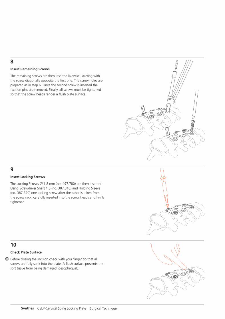
8Insert Remaining Screws
The remaining screws are then inserted likewise, starting withthe screw diagonally opposite the first one. The screw holes areprepared as in step 6. Once the second screw is inserted the fixation pins are removed. Finally, all screws must be tightenedso that the screw heads render a flush plate surface.
9Insert Locking Screws
The Locking Screws � 1.8 mm (no. 497.780) are then inserted.Using Screwdriver Shaft 1.8 (no. 387.310) and Holding Sleeve(no. 387.320) one locking screw after the other is taken fromthe screw rack, carefully inserted into the screw heads and firmlytightened.
10Check Plate Surface
Before closing the incision check with your finger tip that allscrews are fully sunk into the plate. A flush surface prevents thesoft tissue from being damaged (oesophagus!).
MT_0X6.000.062_AB_0X6.000.062_AB 17.02.10 09:28 Seite 6

Bibliography
Morscher E., Sutter F., Jenny H., Olerud S. (1986):Die vordere Verplattung der Halswirbelsäulemit dem Hohlschrauben-Plattensystem aus Titanium.Der Chirurg, 57, pp. 702–707
Jónsson H., Cesarini K., Petrén-Mallmin M., Rauschning W.(1991):Locking Screw-plate Fixation of Cervical Spine Fractureswith and without Ancillary Posterior Plating.Archives of Orthopaedic and Trauma Surgery, 111, pp. 1–12
Grubb M. R., Currier B. L., Bonin V., Grabowski J. J., Chao E. Y.S. (1992):Biomechanical Evaluation of Anterior Cervical Spine Stabilizationin a Porcine Model. Biomechanics Laboratory, Department ofOrthopedics, Mayo Clinic/Mayo Foundation, Rochester, MN55905
Rechtine G. R., Cahill D. W., Gruenberg M., Chrin A. M. (1994):The Synthes Cervical Locking Plate and Screw Systemin Anterior Cervical Fusion.Techniques in Orthopaedics, 9, 1, pp. 86–91
Johnston F. G., Crockard H. A. (1995):One-stage Internal Fixation and Anterior Fusion inComplex Cervical Spinal Disorders.Journal of Neurosurgery, 82, pp. 234–238
Stoll T. M., Morscher E. (1995):Anterior Interbody Fusion Using the Cervical SpineLocking Plate.Orthopaedics and Traumatology, 7, no. 2, pp. 71–83. Commentby M. Blauth, H. Tscherne; pp. 84–86.Response; pp. 86–88
Müller M. E., Allgöwer M., Schneider R., Willenegger H. (1996):Manual of Internal Fixation, 4th edition, Springer Verlag,New York
MT_0X6.000.062_AB_0X6.000.062_AB 17.02.10 09:28 Seite 7

Synthes CSLP-Cervical Spine Locking Plate Surgical Technique
MT_0X6.000.062_AB_0X6.000.062_AB 17.02.10 09:28 Seite 8

MT_0X6.000.062_AB_0X6.000.062_AB 17.02.10 09:28 Seite U3

0123All technique guides are available as PDF files at www.synthes.com/lit
Ö036.000.062öABwä
036.
000.
062
AB
510
5002
9 ©
02/
2010
Syn
thes
, Inc
. or
its a
ffili
ates
A
ll rig
hts
rese
rved
Sy
nthe
s is
a t
rade
mar
k of
Syn
thes
, Inc
. or
its a
ffili
ates
MT_0X6.000.062_AB_0X6.000.062_AB 17.02.10 09:28 Seite U4