Surgical echnique - Acumed | Innovation With Purpose echnique Acu-Loc ® 2 Volar Distal Radius...
36
Surgical Technique Acu-Loc ® 2 Volar Distal Radius Plating System
Transcript of Surgical echnique - Acumed | Innovation With Purpose echnique Acu-Loc ® 2 Volar Distal Radius...

Surgical Technique
Acu-Loc® 2 Volar Distal Radius Plating System

Acumed® is a global leader of innovative orthopaedic and medical solutions.
We are dedicated to developing products, service methods, and approaches that improve patient care.
Definition
Warning Indicates critical information about a potential serious outcome to the patient or the user.
Caution Indicates instructions that must be followed in order to ensure the proper use of the device.
Note Indicates information requiring special attention.
Acumed® Acu-Loc® 2 Volar Distal Radius Plating SystemThe Acu-Loc 2 Wrist Plating System offers plate families and screw technologies to treat multiple fracture patterns of the distal radius and distal ulna regions.
Acumed has introduced the Acu-Loc 2 Volar Distal Radius (VDR) Plating System as the next generation in plating fixation. The system presents several plate options, a unique two-piece locking compression screw, innovative instrumentation for fracture management, and plate placement tools.
Some products shown and/or described may not be available in your distribution area. Please contact your local authorized Acumed distributor for additional information.
Acumed® Acu-Loc® 2 Volar Distal Radius Plating System Surgical Technique
Table of Contents
Acu-Loc 2 System Features . . . . . . . . . . . . . . . . . . . . . . . . . . . . . . . . . . . . . . . . . . . . . . . . . . . . . . 2
Plate Placement Instrumentation . . . . . . . . . . . . . . . . . . . . . . . . . . . . . . . . . . . . . . . . . . . . . . . . . . 8
Instrument Overview . . . . . . . . . . . . . . . . . . . . . . . . . . . . . . . . . . . . . . . . . . . . . . . . . . . . . . . . . . . . 9
Surgical Technique Overview . . . . . . . . . . . . . . . . . . . . . . . . . . . . . . . . . . . . . . . . . . . . . . . . . . . . 12
Surgical Techniques . . . . . . . . . . . . . . . . . . . . . . . . . . . . . . . . . . . . . . . . . . . . . . . . . . . . . . . . . . . . 14
Acu-Loc 2 VDR . . . . . . . . . . . . . . . . . . . . . . . . . . . . . . . . . . . . . . . . . . . . . . . . . . . . . . . . . . . . . 14
Frag-Loc® Compression Screw . . . . . . . . . . . . . . . . . . . . . . . . . . . . . . . . . . . . . . . . . . . . . . . 19
Ordering Information . . . . . . . . . . . . . . . . . . . . . . . . . . . . . . . . . . . . . . . . . . . . . . . . . . . . . . . . . . .22
References . . . . . . . . . . . . . . . . . . . . . . . . . . . . . . . . . . . . . . . . . . . . . . . . . . . . . . . . . . . . . . . . . . . . 31

The standard Acu-Loc 2 Plate is designed to closely replicate the anatomical contours of the distal radius and may assist in restoring the original geometry.
System FeaturesAcu-Loc 2 Volar Distal Radius (VDR) Plates
K-wire holes to assess distal screw positioning relative
to radiocarpal joint
Targeted radial styloid screws angled at 53° and 41°
Suture holes aid in fixation of small articular fragments
Highly polished surface finish
K-wire hole to assess ulnar screw positioning relative to DRUJ
2.3 mm subchondral lunate facet support screw
1 mm increment lines for plate
adjustment
Lateral view of the Acu-Loc 2 VDR Plate showing screw trajectory
Wide, Left and Right Specific
Standard Left and Right Specific
Standard Long, Left and Right Specific
Narrow Long, Left and Right Specific
Narrow Left and Right Specific
25 mm
25 mm
22 mm
22 mm
29 mm
Acu-Loc 2 VDR Plate Options
51 mm68 mm 68 mm
51 mm 59 mm
Acumed® Acu-Loc® 2 Volar Distal Radius Plating System Surgical Technique
2

Acumed® Acu-Loc® 2 Volar Distal Radius Plating System Surgical Technique
3
VDR Proximal Plates are designed to sit approximately 2 mm more proximal than the silver colored plates.
K-wire holes to assess distal screw positioning relative to radiocarpal joint
Targeted radial styloid screws angled at 49° and 41°
Suture holes aid in fixation of small articular fragments
K-wire hole to assess ulnar screw positioning relative to DRUJ
2.3 mm subchondral lunate facet support screw
Locking divergent shaft screw hole
1 mm increment lines for plate adjustment
K-wire holes for provisional stability
System Features [continued]Acu-Loc 2 Volar Distal Radius (VDR) Proximal Plates
Wide, Left and Right Specific
Standard Left and Right Specific
Narrow Left and Right Specific
24 mm 21 mm27 mm
Acu-Loc 2 VDR Proximal Plate Options
49 mm 49 mm 57 mm
Standard Long, Left and Right Specific
24 mm
65 mm
Narrow Long, Left and Right Specific
21 mm
65 mm
Acumed® Acu-Loc® 2 Volar Distal Radius Plating System Surgical Technique
4
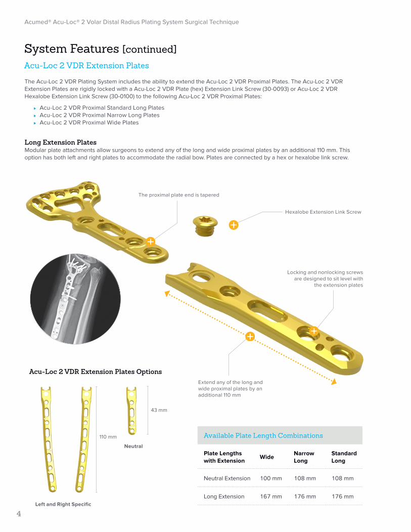
The Acu-Loc 2 VDR Plating System includes the ability to extend the Acu-Loc 2 VDR Proximal Plates. The Acu-Loc 2 VDR Extension Plates are rigidly locked with a Acu-Loc 2 VDR Plate (hex) Extension Link Screw (30-0093) or Acu-Loc 2 VDR Hexalobe Extension Link Screw (30-0100) to the following Acu-Loc 2 VDR Proximal Plates:
⊲ Acu-Loc 2 VDR Proximal Standard Long Plates ⊲ Acu-Loc 2 VDR Proximal Narrow Long Plates ⊲ Acu-Loc 2 VDR Proximal Wide Plates
Long Extension PlatesModular plate attachments allow surgeons to extend any of the long and wide proximal plates by an additional 110 mm. This option has both left and right plates to accommodate the radial bow. Plates are connected by a hex or hexalobe link screw.
Hexalobe Extension Link Screw
System Features [continued]Acu-Loc 2 VDR Extension Plates
The proximal plate end is tapered
Locking and nonlocking screws are designed to sit level with
the extension plates
Extend any of the long and wide proximal plates by an additional 110 mm
110 mm
43 mm
Left and Right Specific
Neutral
Available Plate Length Combinations
Plate Lengths with Extension
WideNarrow Long
Standard Long
Neutral Extension 100 mm 108 mm 108 mm
Long Extension 167 mm 176 mm 176 mm
Acu-Loc 2 VDR Extension Plates Options

Acumed® Acu-Loc® 2 Volar Distal Radius Plating System Surgical Technique
5
The Frag-Loc Compression Screw is a two-part cannulated compression screw designed to reduce dorsal fragments to the Acu-Loc 2 VDR Plates, Acu-Loc VDR Plates, and Acu-Loc EX Plates.
Note: The Frag-Loc Compression Screw may only be used for screw lengths of 16–24 mm and the long Frag-Loc Compression Screw, may be used for lengths of 20–28 mm.
A second 2.3 mm screw may be placed in an adjacent screw hole to prevent rotation of the dorsal bone fragment.
System Features [continued]Frag-Loc® Compression Screw
Frag-Loc Compression Screw(30-0371)
Frag-Loc Compression Screw, Long (30-0372)
Frag-Loc Compression Sleeve(30-0370)

Acumed® Acu-Loc® 2 Volar Distal Radius Plating System Surgical Technique
6
Acu-Loc 2 KickStand PostsWith the introduction of the next generation of distal radius fixation, the Acu-Loc 2 System offers a variety of innovative instrumentation. The KickStand Posts (80-07XX) are threaded plate posts designed to assist with distal radius volar tilt correction by lifting the proximal end of the plate away from the radial shaft to form a stable platform with which to achieve distal screw fixation.
Six different KickStand post angles are offered to assist with corrective osteotomies and dorsally displaced fractures. Five of the KickStand posts are offered in finite increments of 5°, 10°, 15°, 20°, and 25° osteotomy angles. A fully threaded option for fractures allows for volar tilt correction between 5 and 30 degrees.
During an osteotomy, the desired angular correction of the volar aspect of the distal radius determines which KickStand post is selected. A 10° KickStand post will lift the plate approximately 7.5 mm. The chosen KickStand post is threaded into the locking hole just proximal of the adjustment slot of the Acu-Loc 2 VDR Plate prior to plate placement.
System Features [continued] Key Instruments
KickStand Post 5° (80-0718)
KickStand Post 20° (80-0721)
KickStand Post 10° (80-0719)
KickStand Post 25° (80-0722)
KickStand Post 15° (80-0720)
KickStand Post 5–30° (80-0731)
Acumed® Acu-Loc® 2 Volar Distal Radius Plating System Surgical Technique
7
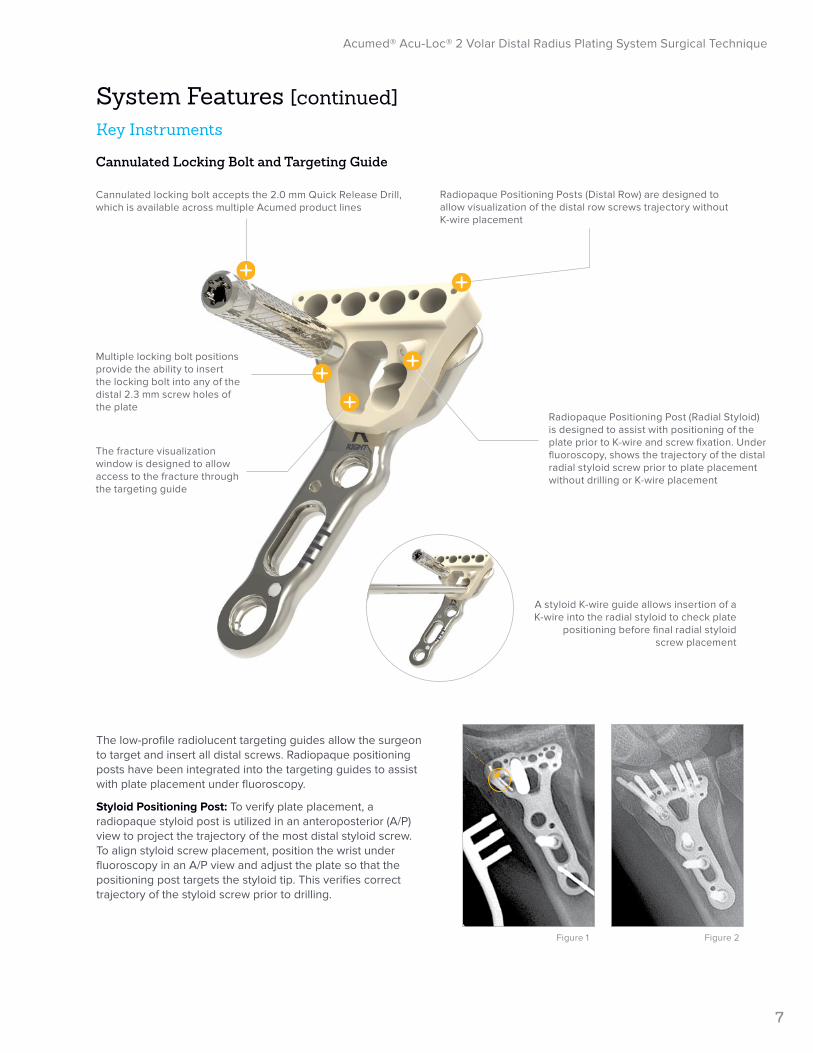
Cannulated Locking Bolt and Targeting Guide
Multiple locking bolt positions provide the ability to insert the locking bolt into any of the distal 2.3 mm screw holes of the plate
The fracture visualization window is designed to allow access to the fracture through the targeting guide
Radiopaque Positioning Posts (Distal Row) are designed to allow visualization of the distal row screws trajectory without K-wire placement
Radiopaque Positioning Post (Radial Styloid) is designed to assist with positioning of the plate prior to K-wire and screw fixation. Under fluoroscopy, shows the trajectory of the distal radial styloid screw prior to plate placement without drilling or K-wire placement
A styloid K-wire guide allows insertion of a K-wire into the radial styloid to check plate
positioning before final radial styloid screw placement
Cannulated locking bolt accepts the 2.0 mm Quick Release Drill, which is available across multiple Acumed product lines
The low-profile radiolucent targeting guides allow the surgeon to target and insert all distal screws. Radiopaque positioning posts have been integrated into the targeting guides to assist with plate placement under fluoroscopy.
Styloid Positioning Post: To verify plate placement, a radiopaque styloid post is utilized in an anteroposterior (A/P) view to project the trajectory of the most distal styloid screw. To align styloid screw placement, position the wrist under fluoroscopy in an A/P view and adjust the plate so that the positioning post targets the styloid tip. This verifies correct trajectory of the styloid screw prior to drilling.
Figure 1 Figure 2
System Features [continued] Key Instruments

The low-profile radiolucent targeting guides allow the surgeon to target and insert all distal screws. Radiopaque positioning posts have been integrated into the targeting guides to assist with plate placement under fluoroscopy.
Styloid Positioning Post (figures 1A and 1B): To verify plate placement, a radiopaque styloid post is utilized in an anteroposterior (A/P) view to project the trajectory of the most distal styloid screw. To align styloid screw placement, position the wrist under fluoroscopy in an A/P view and adjust the plate so that the positioning post targets the styloid tip. This verifies correct trajectory of the styloid screw prior to drilling.
Note: The .054" x 6" K-wire (WS-1406ST) can also be used to verify styloid screw trajectory by inserting the .054" K-Wire into .054" K-wire Guide (80-0688) through the targeting guide screw holes.
Distal Screw Placement (figures 2A and 2B): To verify plate placement from a lateral view, line up the two parallel radiopaque posts. A single plane is created by the goal posts beneath the subchondral bone, showing trajectory of the distal screw row. If the posts do not target into the joint, then the distal screw row will not either. This can be achieved by lifting the hand in neutral rotation so that the forearm is 20 degrees to the surgical table.
The distal K-wire holes in the targeting guides and Acu-Loc 2 VDR plates allow placement of K-wires to also verify plate placement. The K-wire holes are in line with the distal screws of all Acu-Loc 2 VDR plates, allowing the surgeon to verify screw placement.
The plate’s position can then be secured proximally with a .054" x 6" K-wire or Plate Tack (PL-PTACK) and distally with a .054" x 6" K-wire.
VDR Plate Positioning HandleThe VDR Plate Positioning Handle (80-0729) (Figure 3) assists with Acu-Loc 2 VDR plate placement while keeping the surgeon’s hands out of the fluoroscopy beam. Under fluoroscopy, the handle should line up with the center of the plate and radial shaft to show a true A/P view. This is used to help accurately place the proximal shaft of the plate in alignment with the center axis of the radial diaphysis.
Note: The design of the Acu-Loc 2 Plate Positioning Handle maintains access to the K-wire holes and 3.5 mm screw slot on the proximal end of the Acu-Loc 2 VDR plate.
VDR Plate Positioning Handle Assembly ⊲ The Locking Bolt 10–32 (80-0738) is threaded into the left
side of the keyhole of the plate positioning handle base. ⊲ Once engaged, the locking bolt toggles to fit left and
right plates. ⊲ Thread the locking bolt into the most distal 3.5 mm locking
hole on the shaft of any Acu-Loc 2 VDR plate.
Figure 3
Figure 1A Figure 1B
Figure 2A
Incorrect Placement
Figure 2B
Correct Placement
Acumed® Acu-Loc® 2 Volar Distal Radius Plating System Surgical Technique
8
Plate Placement InstrumentationAcu-Loc® 2 VDR Targeting Guides
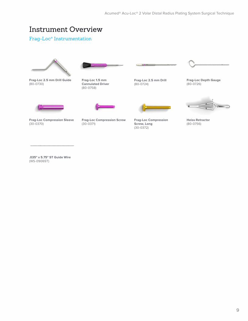
Frag-Loc® Instrumentation
Acumed® Acu-Loc® 2 Volar Distal Radius Plating System Surgical Technique
9
Instrument Overview
Frag-Loc 1.5 mm Cannulated Driver (80-0758)
Frag-Loc Compression Screw (30-0371)
Frag-Loc Depth Gauge (80-0726)
.035" x 5.75" ST Guide Wire (WS-0906ST)
Heiss Retractor (80-0756)
Frag-Loc Compression Screw, Long (30-0372)
Frag-Loc 2.5 mm Drill (80-0724)
Frag-Loc 2.5 mm Drill Guide (80-0730)
Frag-Loc Compression Sleeve (30-0370)
Acumed® Acu-Loc® 2 Volar Distal Radius Plating System Surgical Technique
10
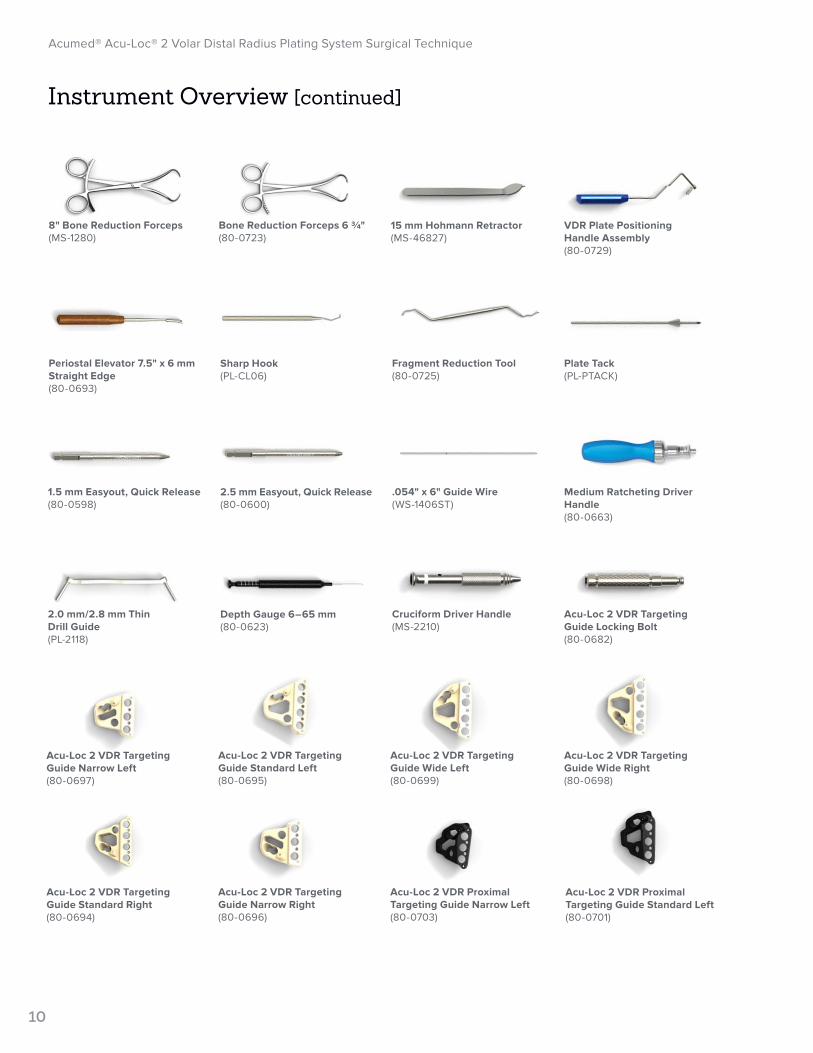
Instrument Overview [continued]
Acu-Loc 2 VDR Proximal Targeting Guide Standard Left(80-0701)
Depth Gauge 6–65 mm(80-0623)
Sharp Hook(PL-CL06)
Acu-Loc 2 VDR Targeting Guide Narrow Left(80-0697)
2.5 mm Easyout, Quick Release (80-0600)
Acu-Loc 2 VDR Targeting Guide Standard Right(80-0694)
15 mm Hohmann Retractor(MS-46827)
Medium Ratcheting Driver Handle (80-0663)
1.5 mm Easyout, Quick Release (80-0598)
Acu-Loc 2 VDR Targeting Guide Wide Right(80-0698)
VDR Plate Positioning Handle Assembly(80-0729)
Acu-Loc 2 VDR Targeting Guide Wide Left(80-0699)
Plate Tack(PL-PTACK)
Acu-Loc 2 VDR Proximal Targeting Guide Narrow Left (80-0703)
Fragment Reduction Tool(80-0725)
Acu-Loc 2 VDR Targeting Guide Standard Left(80-0695)
.054" x 6" Guide Wire(WS-1406ST)
Acu-Loc 2 VDR Targeting Guide Narrow Right(80-0696)
Bone Reduction Forceps 6 ¾"(80-0723)
Cruciform Driver Handle(MS-2210)
8" Bone Reduction Forceps(MS-1280)
2.0 mm/2.8 mm Thin Drill Guide(PL-2118)
Periostal Elevator 7.5" x 6 mm Straight Edge(80-0693)
Acu-Loc 2 VDR Targeting Guide Locking Bolt(80-0682)

Acumed® Acu-Loc® 2 Volar Distal Radius Plating System Surgical Technique
11
Instrument Overview [continued]
Drill Guide/Depth Gauge for 2.0 mm Drill(MS-DG23)
.054" K-wire Guide(80-0688)
2.0 mm Quick Release Drill(80-0318)
Distal Radius Probe(MS-DRPB)
T15 Stick Fit Hexalobe Driver(80-0760)
2.3 mm Screw Sleeve, Locking Tab(80-0727)
2.8 mm Locking Drill Guide 6–26 mm(80-2006)
2.0 mm Locking Drill Guide 4–32 mm(80-0249)
2.8 mm Quick Release Drill(80-0387)
1.5 mm Hex Driver Tip, Locking Groove(80-0728)
2.8 mm x 5" Quick Release Drill(80-2008)
2.8 mm Hexalobe Locking Drill Guide 6–65 mm(80-0668)
3.5 mm Locking Screw Bone Tap(80-2126)
Acu-Loc 2 VDR Proximal Targeting Guide Wide Left(80-0705)
Acu-Loc 2 VDR Proximal Targeting Guide Standard Right(80-0700)
Acu-Loc 2 VDR Proximal Targeting Guide Wide Right(80-0704)
Acu-Loc 2 VDR Proximal Targeting Guide Narrow Right(80-0702)
Optional

12
Acumed® Acu-Loc® 2 Volar Distal Radius Plating System Surgical Technique
Surgical Technique Overview
Acu-Loc 2 VDR Surgical Technique
ExposurePlate Selection and PlacementFracture Reduction
Frag-Loc® Compression Screw Surgical Technique
Drilling BicorticallFrag-Loc Sleeve Insertion
Drilling Unicortically
Measuring to Determine Screw Type
13
Acumed® Acu-Loc® 2 Volar Distal Radius Plating System Surgical Technique
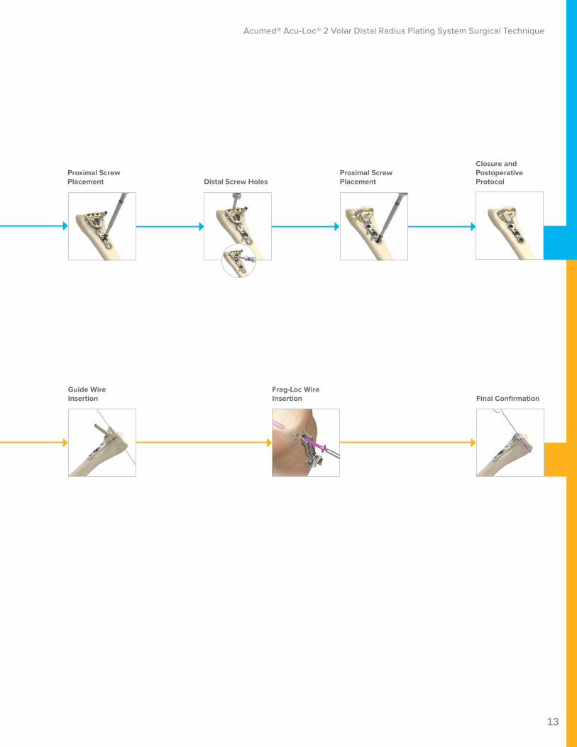
Distal Screw Holes
Closure and Postoperative Protocol
Proximal Screw Placement
Proximal Screw Placement
Guide Wire Insertion Final Confirmation
Frag-Loc Wire Insertion

14
Acumed® Acu-Loc® 2 Volar Distal Radius Plating System Surgical Technique
Acu-Loc 2 VDR Plate (70-03XX)
Fragment Reduction Tool (80-0725)
Figure 1
Figure 2
Figure 3
Figure 4 Figure 5
Acu-Loc 2 VDR Surgical TechniqueWilliam B. Geissler, MD David S. Ruch, MD Mr. Daniel J. Brown, FRCS 1 Exposure
Supinate the patient’s forearm to expose the surgical site. To maximize exposure, place a towel under the wrist, supporting it in extension. Make a longitudinal incision approximately 6 cm in length just radial to the flexor carpi radialis (FCR) tendon to protect against injury to the palmar cutaneous branch of the median nerve.
Open the sheath and retract the FCR tendon radially to protect the radial artery. Identify the flexor pollicis longus (FPL) muscle by passive flexion/extension of the thumb interphalangeal joint and retract ulnarly to protect the median nerve. Next, identify the pronator quadratus by its transverse fibers and release radially to ulnarly to expose the fracture site.
2 Fracture ReductionThe brachioradialis may need to be released from
its insertion on the radial styloid to facilitate reduction and visualization of the fracture. Reduce the fracture using manual techniques. Provisional stability can be achieved with K-wires and evaluated under fluoroscopy.
Fragment Reduction Tool (80-0725): Use this tool for articular reconstruction. A broad mallet (Figure 4) and narrow thin (Figure 5) tip provide the ability to lift and position articular fracture fragments through the plate window when possible.
Fixating Small Volar Ulnar Corner Fragments:This Technique uses the Acu-Loc 2 VDR Plate (70-03XX). The volar ulnar fragment is typically rotated with its capsular attachment and de-rotated under direct visualization. Multiple sutures are placed in the capsule, rotating the fragment back anatomically.
Once the fragment is de-rotated, the sutures are passed through the suture holes in the volar ulnar corner of the plate. A plate-specific nonlocking screw is placed through the oblong slot in the plate. The plate is positioned onto the distal radius, with the preferred placement confirmed using fluoroscopy. The sutures are tied, securing the volar ulnar fragment with the plate, and the remaining screws are placed.1
Acu-Loc 2 Plate Reference ChartSilver Colored VDR Plates offer more distal plate
coverage and subchondral support
Gold Colored VDR Proximal Plates are designed to sit approximately 2 mm more proximal than the Standard plates
15
Acumed® Acu-Loc® 2 Volar Distal Radius Plating System Surgical Technique
Acu-Loc 2 VDR Extension Plate(70-036X)
Acu-Loc 2 VDR Extension Link Screw (30-0XXX)
T15 Stick Fit Hexalobe Driver(80-0760)
Acu-Loc 2 VDR T-Guide Locking Bolt (80-0682)
VDR Plate Positioning Handle (80-0729)
2.5 mm Quick Release Hex Driver (HPC-0025)
Acu-Loc 2 VDR Targeting Guide(80-06XX)
Acu-Loc 2 VDR Proximal Targeting Guide(80-07XX)
Acu-Loc 2 VDR Surgical Technique [continued]
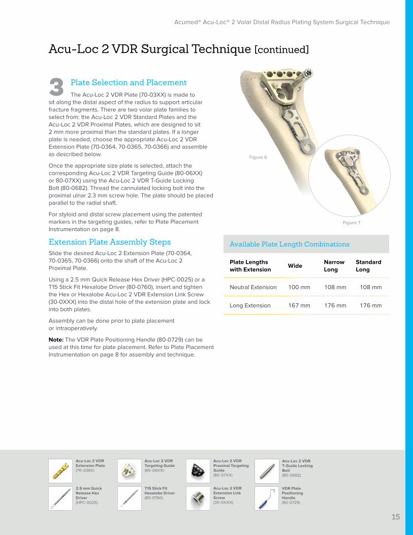
3 Plate Selection and PlacementThe Acu-Loc 2 VDR Plate (70-03XX) is made to
sit along the distal aspect of the radius to support articular fracture fragments. There are two volar plate families to select from: the Acu-Loc 2 VDR Standard Plates and the Acu-Loc 2 VDR Proximal Plates, which are designed to sit 2 mm more proximal than the standard plates. If a longer plate is needed, choose the appropriate Acu-Loc 2 VDR Extension Plate (70-0364, 70-0365, 70-0366) and assemble as described below.
Once the appropriate size plate is selected, attach the corresponding Acu-Loc 2 VDR Targeting Guide (80-06XX) or 80-07XX) using the Acu-Loc 2 VDR T-Guide Locking Bolt (80-0682). Thread the cannulated locking bolt into the proximal ulnar 2.3 mm screw hole. The plate should be placed parallel to the radial shaft.
For styloid and distal screw placement using the patented markers in the targeting guides, refer to Plate Placement Instrumentation on page 8.
Extension Plate Assembly Steps Slide the desired Acu-Loc 2 Extension Plate (70-0364, 70-0365, 70-0366) onto the shaft of the Acu-Loc 2 Proximal Plate.
Using a 2.5 mm Quick Release Hex Driver (HPC-0025) or a T15 Stick Fit Hexalobe Driver (80-0760), insert and tighten the Hex or Hexalobe Acu-Loc 2 VDR Extension Link Screw (30-0XXX) into the distal hole of the extension plate and lock into both plates.
Assembly can be done prior to plate placement or intraoperatively.
Note: The VDR Plate Positioning Handle (80-0729) can be used at this time for plate placement. Refer to Plate Placement Instrumentation on page 8 for assembly and technique.
Available Plate Length Combinations
Plate Lengths with Extension
WideNarrow Long
Standard Long
Neutral Extension 100 mm 108 mm 108 mm
Long Extension 167 mm 176 mm 176 mm
Figure 6
Figure 7
16
Acumed® Acu-Loc® 2 Volar Distal Radius Plating System Surgical Technique
.054" x 6" Guide Wire(WS-1406ST)Also used as a K-wire
2.8 mm Quick Release Drill(80-0387)
2.0 mm Drill Guide/Depth Gauge(MS-DG23)
2.0 mm/2.8 mm Thin Drill Guide(PL-2118)
Distal Radius Depth Probe(MS-DRPB)
3.5 mm Locking Screw Bone Tap(80-2126)
3.5 mm Nonlocking Hexalobe Screw(30-02XX)
3.5 mm Nonlocking Hex (Cortical) Screw(CO-31XX)
2.0 mm Quick Release Drill(80-0318)
Depth Gauge 6–65 mm(80-0623)
Acu-Loc 2 VDR Surgical Technique [continued]
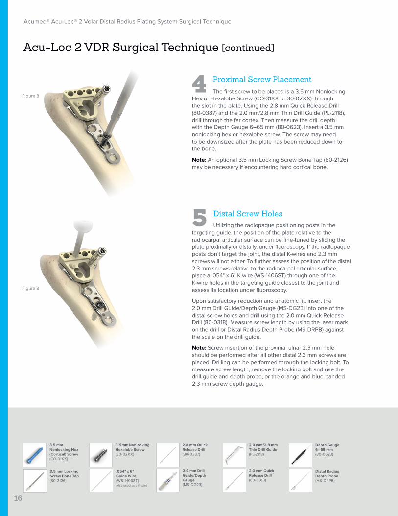
4 Proximal Screw PlacementThe first screw to be placed is a 3.5 mm Nonlocking
Hex or Hexalobe Screw (CO-31XX or 30-02XX) through the slot in the plate. Using the 2.8 mm Quick Release Drill (80-0387) and the 2.0 mm/2.8 mm Thin Drill Guide (PL-2118), drill through the far cortex. Then measure the drill depth with the Depth Gauge 6–65 mm (80-0623). Insert a 3.5 mm nonlocking hex or hexalobe screw. The screw may need to be downsized after the plate has been reduced down to the bone.
Note: An optional 3.5 mm Locking Screw Bone Tap (80-2126) may be necessary if encountering hard cortical bone.
5 Distal Screw HolesUtilizing the radiopaque positioning posts in the
targeting guide, the position of the plate relative to the radiocarpal articular surface can be fine-tuned by sliding the plate proximally or distally, under fluoroscopy. If the radiopaque posts don’t target the joint, the distal K-wires and 2.3 mm screws will not either. To further assess the position of the distal 2.3 mm screws relative to the radiocarpal articular surface, place a .054" x 6" K-wire (WS-1406ST) through one of the K-wire holes in the targeting guide closest to the joint and assess its location under fluoroscopy.
Upon satisfactory reduction and anatomic fit, insert the 2.0 mm Drill Guide/Depth Gauge (MS-DG23) into one of the distal screw holes and drill using the 2.0 mm Quick Release Drill (80-0318). Measure screw length by using the laser mark on the drill or Distal Radius Depth Probe (MS-DRPB) against the scale on the drill guide.
Note: Screw insertion of the proximal ulnar 2.3 mm hole should be performed after all other distal 2.3 mm screws are placed. Drilling can be performed through the locking bolt. To measure screw length, remove the locking bolt and use the drill guide and depth probe, or the orange and blue-banded 2.3 mm screw depth gauge.
Figure 8
Figure 9

17
Acumed® Acu-Loc® 2 Volar Distal Radius Plating System Surgical Technique
2.3 mm Locking Cortical Screws(CO-T23XX)
Frag-Loc Compression Screw(30-037X)
2.3 mmScrew Sleeve, the Locking Tab(80-0727)
2.3 mm Locking Cortical Pegs (CO-S23XX)
Cruciform Driver Handle (MS-2210)
2.3 mm Nontoggling Cortical Screws(CO-N23XX)
1.5 mm Hex Driver Tip, Locking Groove (80-0728)
2.0 mm Locking Drill Guide 4 mm–32 mm(80-0249)
2.8 mm Locking Drill Guide(80-0384 or 80-0668)
2.8 mm Quick Release Drill (80-0387)
Medium Ratcheting Driver Handle(80-0663)
3.5 mm Locking Screw Bone Tap (80-2126)
3.5 mm Locking Hex (Cortical) Screw (COL-30XX)
Acu-Loc 2 VDR Surgical Technique [continued]
Distal Screw Options: The four options of 2.3 mm screws that can be used distally are fully threaded Locking Cortical Screws (gold) (CO-T23XX), Locking Cortical Pegs (bronze) (CO-S23XX), Nontoggling Cortical Screws (silver) (CO-N23XX), and the Frag-Loc® Compression Screw (30-037X). All 2.3 mm screws are inserted using the 1.5 mm Hex Driver Tip, the Locking Groove (80-0728), the 2.3 mm Screw Sleeve, the Locking Tab (80-0727), and the silver Cruciform Driver Handle (MS-2210).
Styloid Screw Placement: The radial styloid screws are designed to specifically target and support the radial styloid. Insert the drill guide into either styloid hole located in the dual slot on the back of the targeting guide and continue the same screw measurement and placement process for both styloid screws.
Note: It is recommended that the entire distal row and the two radial styloid holes be filled with screws.
Note: An individual 2.0 mm Locking Drill Guide 4 mm–32 mm (80-0249) is available in the system as an alternative for drilling the distal holes. Screw length can be read using the depth probe or 2.3 mm screw depth gauge.
6 Proximal Screw PlacementInsert the threaded 2.8 mm Locking Drill Guide
(80-0384 or 80-0668) into the screw hole distal to the slot, drill with the 2.8 mm Quick Release Drill (80-0387), and measure with the depth gauge. Insert the proper length 3.5 mm Locking Hex or Hexalobe Screw (COL-30XX or 30-023X). Take care that the screw does not exit the bone dorsally. Using the same process, drill and place the final locking screw.
Note: 3.5 mm locking or nonlocking hex or hexalobe screws can be used in the proximal round locking holes. Depending on the bone quality of the patient and at the surgeon’s discretion, 3.5 mm nonlocking hex or hexalobe screws may be preferred to use in the round locking holes.
An optional 3.5 mm Locking Screw Bone Tap (80-2126) may be necessary if encountering hard cortical bone.
Figure 10
Figure 11
Figure 12
3.5 mm Locking Hexalobe Screw (30-023X)
18
Acumed® Acu-Loc® 2 Volar Distal Radius Plating System Surgical Technique
2.5 mm Hex Driver Tip (HPC-0025)
T15 Stick Fit Hexalobe Driver Tip (80-0760)
Medium Ratcheting Driver Handle(80-0663)
1.5 mm Hex Driver Tip, Locking Groove (80-0728)
Cruciform Driver Handle (MS-2210)
Acu-Loc 2 VDR Surgical Technique [continued]
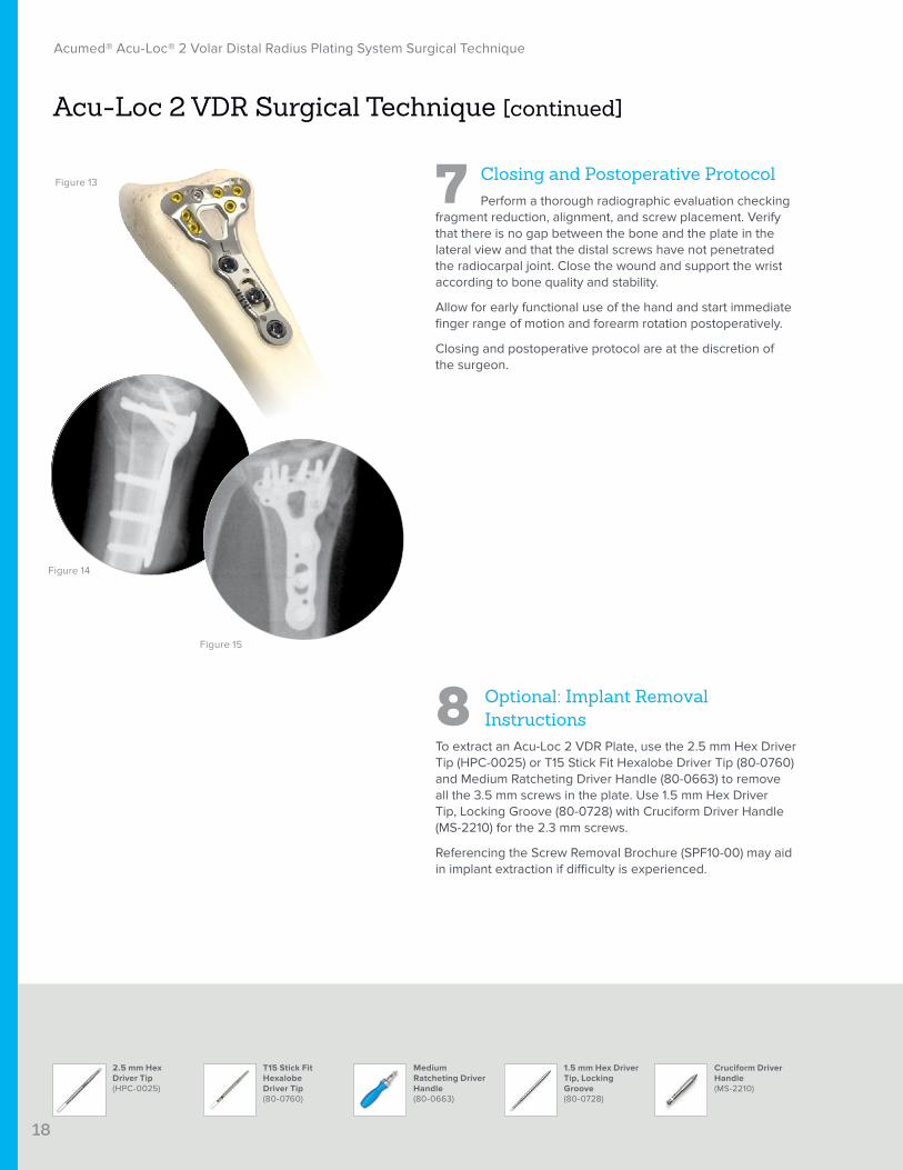
7 Closing and Postoperative ProtocolPerform a thorough radiographic evaluation checking
fragment reduction, alignment, and screw placement. Verify that there is no gap between the bone and the plate in the lateral view and that the distal screws have not penetrated the radiocarpal joint. Close the wound and support the wrist according to bone quality and stability.
Allow for early functional use of the hand and start immediate finger range of motion and forearm rotation postoperatively.
Closing and postoperative protocol are at the discretion of the surgeon.
8 Optional: Implant Removal Instructions
To extract an Acu-Loc 2 VDR Plate, use the 2.5 mm Hex Driver Tip (HPC-0025) or T15 Stick Fit Hexalobe Driver Tip (80-0760) and Medium Ratcheting Driver Handle (80-0663) to remove all the 3.5 mm screws in the plate. Use 1.5 mm Hex Driver Tip, Locking Groove (80-0728) with Cruciform Driver Handle (MS-2210) for the 2.3 mm screws.
Referencing the Screw Removal Brochure (SPF10-00) may aid in implant extraction if difficulty is experienced.
Figure 13
Figure 14
Figure 15
19
Acumed® Acu-Loc® 2 Volar Distal Radius Plating System Surgical Technique
Frag-Loc® Compression Screw Surgical Technique
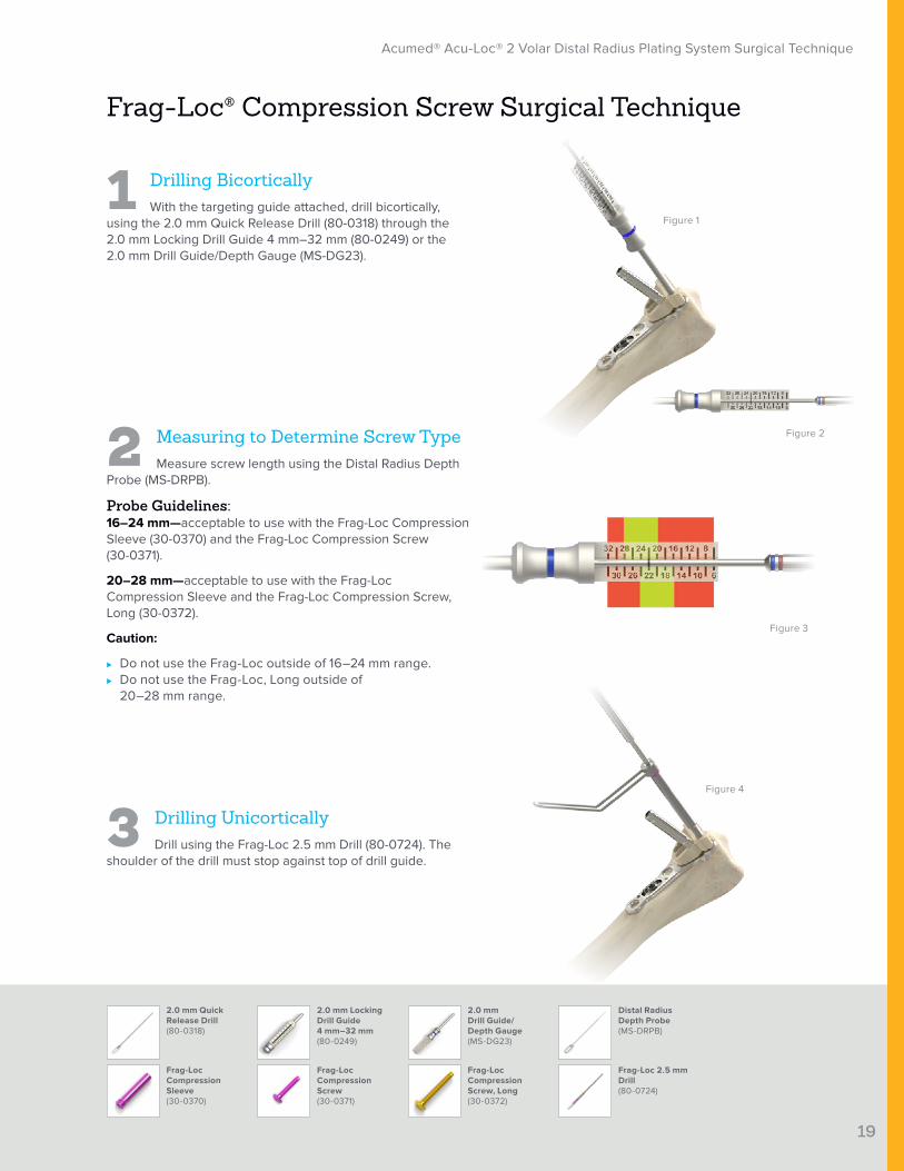
1 Drilling BicorticallyWith the targeting guide attached, drill bicortically,
using the 2.0 mm Quick Release Drill (80-0318) through the 2.0 mm Locking Drill Guide 4 mm–32 mm (80-0249) or the 2.0 mm Drill Guide/Depth Gauge (MS-DG23).
2 Measuring to Determine Screw TypeMeasure screw length using the Distal Radius Depth
Probe (MS-DRPB).
Probe Guidelines:16–24 mm—acceptable to use with the Frag-Loc Compression Sleeve (30-0370) and the Frag-Loc Compression Screw (30-0371).
20–28 mm—acceptable to use with the Frag-Loc Compression Sleeve and the Frag-Loc Compression Screw, Long (30-0372).
Caution:
⊲ Do not use the Frag-Loc outside of 16–24 mm range. ⊲ Do not use the Frag-Loc, Long outside of
20–28 mm range.
3 Drilling UnicorticallyDrill using the Frag-Loc 2.5 mm Drill (80-0724). The
shoulder of the drill must stop against top of drill guide.
Figure 1
Figure 4
Figure 2
Figure 3
Frag-Loc Compression Sleeve (30-0370)
2.0 mm Quick Release Drill (80-0318)
Frag-Loc Compression Screw, Long (30-0372)
2.0 mm Drill Guide/ Depth Gauge (MS-DG23)
Frag-Loc Compression Screw (30-0371)
2.0 mm Locking Drill Guide 4 mm–32 mm (80-0249)
Frag-Loc 2.5 mm Drill (80-0724)
Distal Radius Depth Probe (MS-DRPB)

4 Frag-Loc Sleeve InsertionInsert the Frag-Loc Compression Sleeve (30-0370)
into the plate using the silver Cruciform Driver Handle (MS-2210) with the 1.5 mm Hex Driver Tip and Locking Groove (80-0728).
5 K-wire InsertionInsert the .035" x 5.75" K-wire (WS-0906ST) through
the Frag-Loc Compression Sleeve and dorsal skin.
20
Acumed® Acu-Loc® 2 Volar Distal Radius Plating System Surgical Technique
Frag-Loc Compression Sleeve (30-0370)
Cruciform Driver Handle (MS-2210)
.035" x 5.75" Guide Wire(WS-0906ST)Also used as a K-wire
1.5 mm Hex Driver Tip, Locking Groove (80-0728)
Frag-Loc® Compression Screw Surgical Technique [continued]
Figure 5
Figure 6
Figure 7
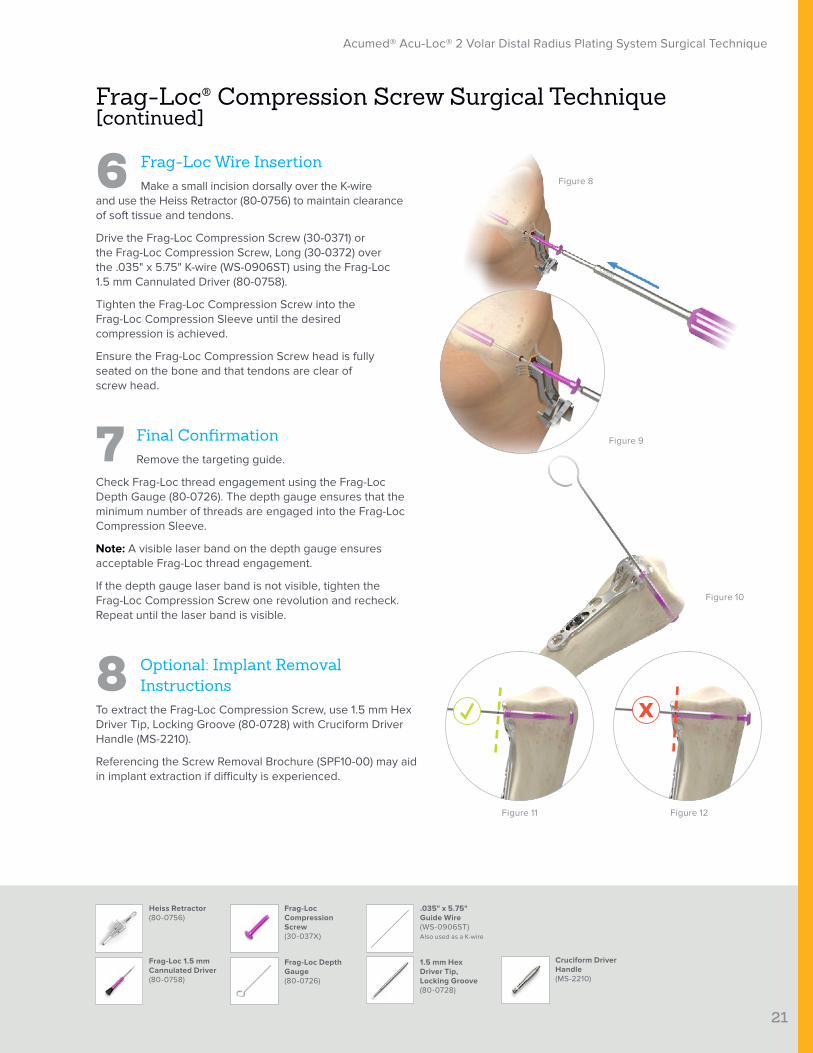
6 Frag-Loc Wire InsertionMake a small incision dorsally over the K-wire
and use the Heiss Retractor (80-0756) to maintain clearance of soft tissue and tendons.
Drive the Frag-Loc Compression Screw (30-0371) or the Frag-Loc Compression Screw, Long (30-0372) over the .035" x 5.75" K-wire (WS-0906ST) using the Frag-Loc 1.5 mm Cannulated Driver (80-0758).
Tighten the Frag-Loc Compression Screw into the Frag-Loc Compression Sleeve until the desired compression is achieved.
Ensure the Frag-Loc Compression Screw head is fully seated on the bone and that tendons are clear of screw head.
7 Final ConfirmationRemove the targeting guide.
Check Frag-Loc thread engagement using the Frag-Loc Depth Gauge (80-0726). The depth gauge ensures that the minimum number of threads are engaged into the Frag-Loc Compression Sleeve.
Note: A visible laser band on the depth gauge ensures acceptable Frag-Loc thread engagement.
If the depth gauge laser band is not visible, tighten the Frag-Loc Compression Screw one revolution and recheck. Repeat until the laser band is visible.
8 Optional: Implant Removal Instructions
To extract the Frag-Loc Compression Screw, use 1.5 mm Hex Driver Tip, Locking Groove (80-0728) with Cruciform Driver Handle (MS-2210).
Referencing the Screw Removal Brochure (SPF10-00) may aid in implant extraction if difficulty is experienced.
1.5 mm Hex Driver Tip, Locking Groove (80-0728)
21
Acumed® Acu-Loc® 2 Volar Distal Radius Plating System Surgical Technique
Frag-Loc® Compression Screw Surgical Technique [continued]
Figure 8
Figure 9
Figure 10
Figure 11 Figure 12
Heiss Retractor (80-0756)
Frag-Loc Depth Gauge (80-0726)
.035" x 5.75" Guide Wire (WS-0906ST)Also used as a K-wire
Frag-Loc 1.5 mm Cannulated Driver (80-0758)
Frag-Loc Compression Screw (30-037X)
Cruciform Driver Handle (MS-2210)
22
Acumed® Acu-Loc® 2 Volar Distal Radius Plating System Surgical Technique
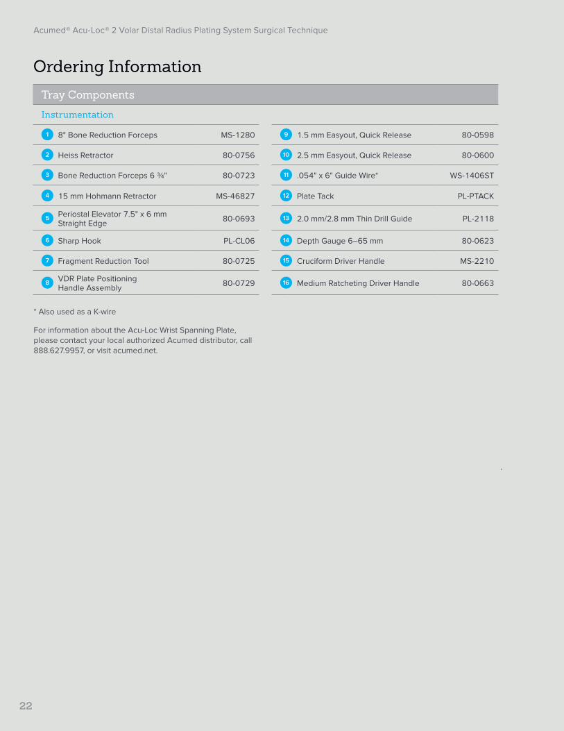
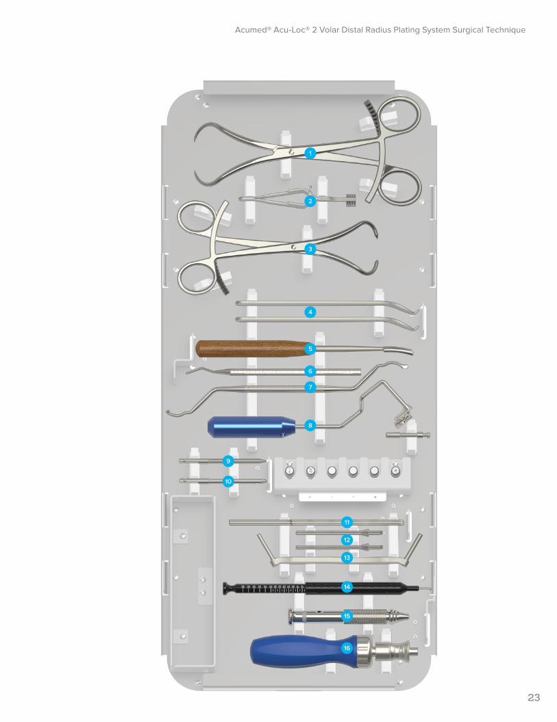
Ordering InformationTray Components
Instrumentation
1 8" Bone Reduction Forceps MS-1280 9 1.5 mm Easyout, Quick Release 80-0598
2 Heiss Retractor 80-0756 10 2.5 mm Easyout, Quick Release 80-0600
3 Bone Reduction Forceps 6 ¾" 80-0723 11 .054" x 6" Guide Wire* WS-1406ST
4 15 mm Hohmann Retractor MS-46827 12 Plate Tack PL-PTACK
5 Periostal Elevator 7.5" x 6 mm Straight Edge 80-0693 13 2.0 mm/2.8 mm Thin Drill Guide PL-2118
6 Sharp Hook PL-CL06 14 Depth Gauge 6–65 mm 80-0623
7 Fragment Reduction Tool 80-0725 15 Cruciform Driver Handle MS-2210
8 VDR Plate Positioning Handle Assembly 80-0729 16 Medium Ratcheting Driver Handle 80-0663
* Also used as a K-wire
For information about the Acu-Loc Wrist Spanning Plate, please contact your local authorized Acumed distributor, call 888.627.9957, or visit acumed.net.
Acumed® Acu-Loc® 2 Volar Distal Radius Plating System Surgical Technique
23
1
2
3
4
5
6
7
8
9
10
11
12
13
14
15
16
24
Acumed® Acu-Loc® 2 Volar Distal Radius Plating System Surgical Technique
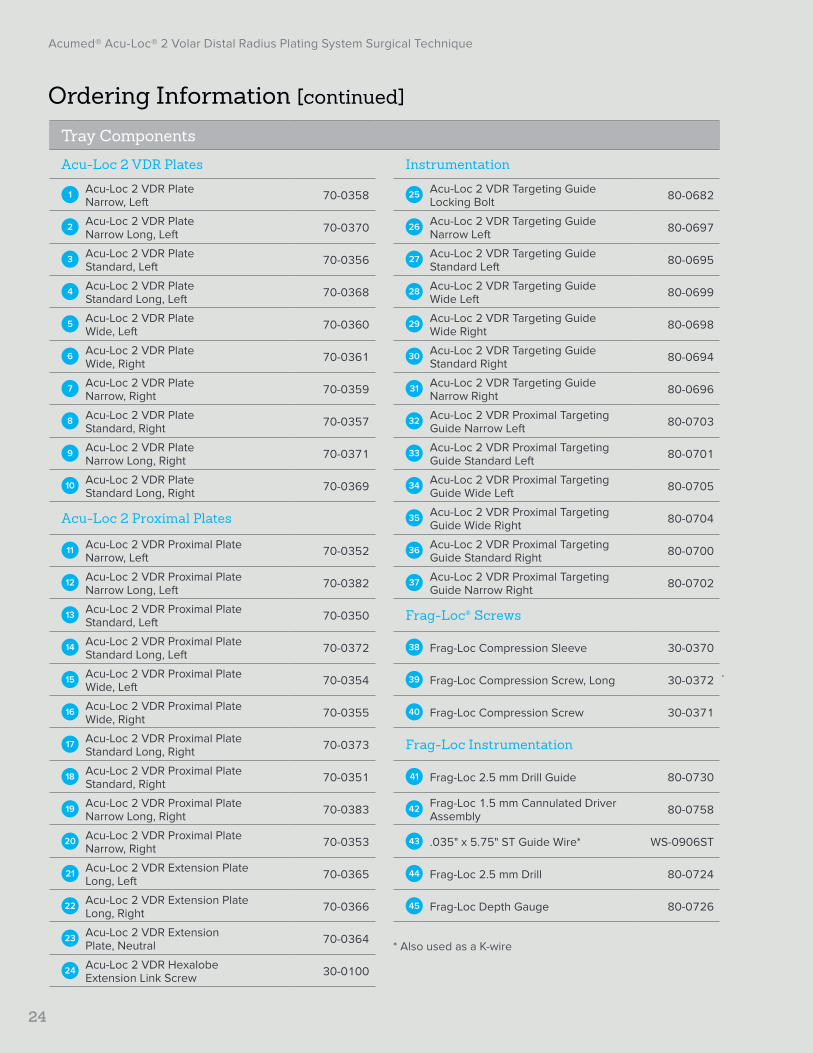
Ordering Information [continued]
Tray Components
Acu-Loc 2 VDR Plates Instrumentation
1 Acu-Loc 2 VDR Plate Narrow, Left 70-0358 25 Acu-Loc 2 VDR Targeting Guide
Locking Bolt 80-0682
2 Acu-Loc 2 VDR Plate Narrow Long, Left 70-0370 26 Acu-Loc 2 VDR Targeting Guide
Narrow Left 80-0697
3 Acu-Loc 2 VDR Plate Standard, Left 70-0356 27 Acu-Loc 2 VDR Targeting Guide
Standard Left 80-0695
4 Acu-Loc 2 VDR Plate Standard Long, Left 70-0368 28 Acu-Loc 2 VDR Targeting Guide
Wide Left 80-0699
5 Acu-Loc 2 VDR Plate Wide, Left 70-0360 29 Acu-Loc 2 VDR Targeting Guide
Wide Right 80-0698
6 Acu-Loc 2 VDR Plate Wide, Right 70-0361 30 Acu-Loc 2 VDR Targeting Guide
Standard Right 80-0694
7 Acu-Loc 2 VDR Plate Narrow, Right 70-0359 31 Acu-Loc 2 VDR Targeting Guide
Narrow Right 80-0696
8 Acu-Loc 2 VDR Plate Standard, Right 70-0357 32 Acu-Loc 2 VDR Proximal Targeting
Guide Narrow Left 80-0703
9 Acu-Loc 2 VDR Plate Narrow Long, Right 70-0371 33 Acu-Loc 2 VDR Proximal Targeting
Guide Standard Left 80-0701
10 Acu-Loc 2 VDR Plate Standard Long, Right 70-0369 34 Acu-Loc 2 VDR Proximal Targeting
Guide Wide Left 80-0705
Acu-Loc 2 Proximal Plates 35 Acu-Loc 2 VDR Proximal Targeting Guide Wide Right 80-0704
11 Acu-Loc 2 VDR Proximal Plate Narrow, Left 70-0352 36 Acu-Loc 2 VDR Proximal Targeting
Guide Standard Right 80-0700
12 Acu-Loc 2 VDR Proximal Plate Narrow Long, Left 70-0382 37 Acu-Loc 2 VDR Proximal Targeting
Guide Narrow Right 80-0702
13 Acu-Loc 2 VDR Proximal Plate Standard, Left 70-0350 Frag-Loc® Screws
14 Acu-Loc 2 VDR Proximal Plate Standard Long, Left 70-0372 38 Frag-Loc Compression Sleeve 30-0370
15 Acu-Loc 2 VDR Proximal Plate Wide, Left 70-0354 39 Frag-Loc Compression Screw, Long 30-0372
16 Acu-Loc 2 VDR Proximal Plate Wide, Right 70-0355 40 Frag-Loc Compression Screw 30-0371
17 Acu-Loc 2 VDR Proximal Plate Standard Long, Right 70-0373 Frag-Loc Instrumentation
18 Acu-Loc 2 VDR Proximal Plate Standard, Right 70-0351 41 Frag-Loc 2.5 mm Drill Guide 80-0730
19 Acu-Loc 2 VDR Proximal Plate Narrow Long, Right 70-0383 42 Frag-Loc 1.5 mm Cannulated Driver
Assembly 80-0758
20 Acu-Loc 2 VDR Proximal Plate Narrow, Right 70-0353 43 .035" x 5.75" ST Guide Wire* WS-0906ST
21 Acu-Loc 2 VDR Extension Plate Long, Left 70-0365 44 Frag-Loc 2.5 mm Drill 80-0724
22 Acu-Loc 2 VDR Extension Plate Long, Right 70-0366 45 Frag-Loc Depth Gauge 80-0726
23 Acu-Loc 2 VDR Extension Plate, Neutral 70-0364
24 Acu-Loc 2 VDR Hexalobe Extension Link Screw 30-0100
* Also used as a K-wire

Acumed® Acu-Loc® 2 Volar Distal Radius Plating System Surgical Technique
25
1 625
25
8 10
2
26
11
12
32 33 34
21
22
24 23
35 36 37
14 17 19
13 15 16 18 20
27 28 29 30 31
7
38
39 40
41
42 43 44 45
9
3
4
5
26
Acumed® Acu-Loc® 2 Volar Distal Radius Plating System Surgical Technique
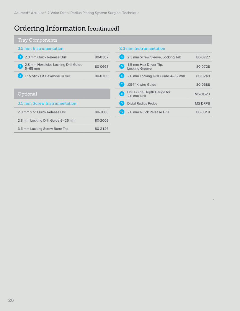
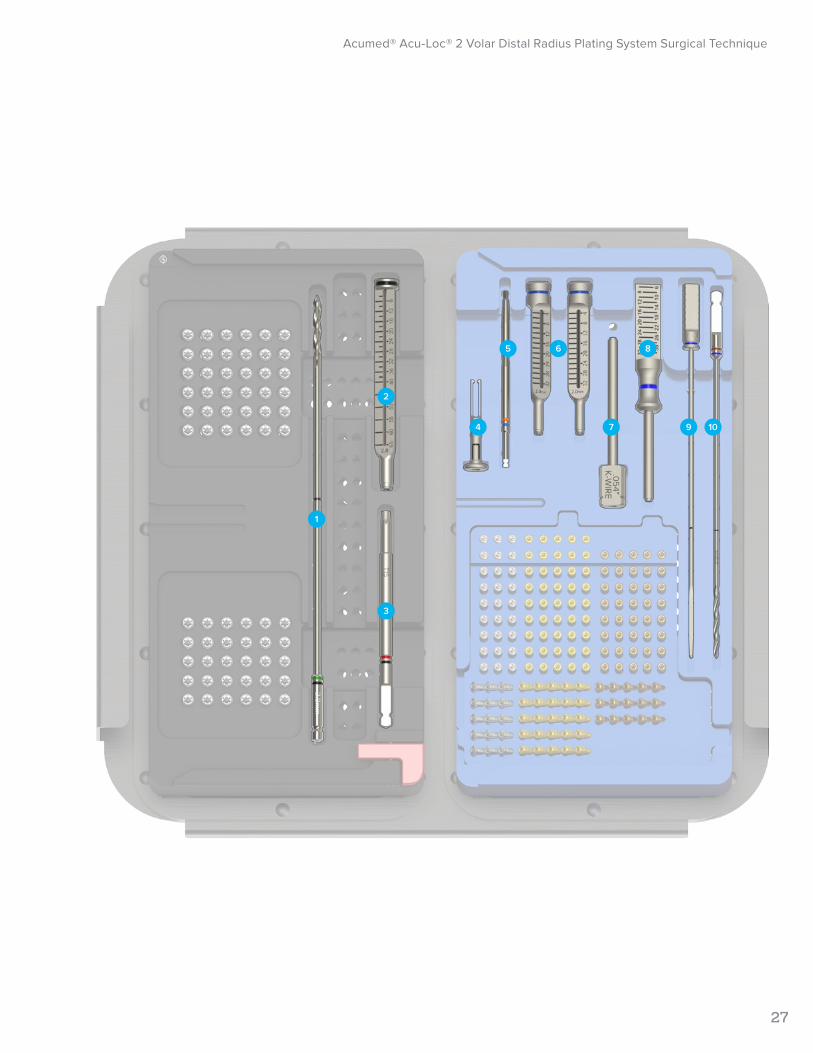
Ordering Information [continued]
Tray Components
3.5 mm Instrumentation 2.3 mm Instrumentation
1 2.8 mm Quick Release Drill 80-0387 4 2.3 mm Screw Sleeve, Locking Tab 80-0727
2 2.8 mm Hexalobe Locking Drill Guide 6–65 mm 80-0668 5 1.5 mm Hex Driver Tip,
Locking Groove 80-0728
3 T15 Stick Fit Hexalobe Driver 80-0760 6 2.0 mm Locking Drill Guide 4–32 mm 80-0249
7 .054" K-wire Guide 80-0688
Optional 8 Drill Guide/Depth Gauge for 2.0 mm Drill MS-DG23
3.5 mm Screw Instrumentation 9 Distal Radius Probe MS-DRPB
2.8 mm x 5" Quick Release Drill 80-2008 10 2.0 mm Quick Release Drill 80-0318
2.8 mm Locking Drill Guide 6–26 mm 80-2006
3.5 mm Locking Screw Bone Tap 80-2126
Acumed® Acu-Loc® 2 Volar Distal Radius Plating System Surgical Technique
27
1
2
3
4 7 9 10
5 6 8

28
Acumed® Acu-Loc® 2 Volar Distal Radius Plating System Surgical Technique
Ordering Information [continued]
2.3 mm Screws
2.3 mm Nontoggling Cortical Screws
2.3 mm x 8 mm Nontoggling Cortical Screw CO-N2308 2.3 mm x 24 mm Nontoggling
Cortical Screw CO-N2324
2.3 mm x 10 mm Nontoggling Cortical Screw CO-N2310 2.3 mm x 26 mm Nontoggling
Cortical Screw CO-N2326
2.3 mm x 12 mm Nontoggling Cortical Screw CO-N2312 2.3 mm x 28 mm Nontoggling
Cortical Screw CO-N2328
2.3 mm x 14 mm Nontoggling Cortical Screw CO-N2314 2.3 mm x 30 mm Nontoggling
Cortical Screw CO-N2330
2.3 mm x 16 mm Nontoggling Cortical Screw CO-N2316 2.3 mm x 32 mm Nontoggling
Cortical Screw CO-N2332
2.3 mm x 18 mm Nontoggling Cortical Screw CO-N2318 2.3 mm x 28 mm Nontoggling
Cortical Screw CO-N2328
2.3 mm x 20 mm Nontoggling Cortical Screw CO-N2320 2.3 mm x 30 mm Nontoggling
Cortical Screw CO-N2330
2.3 mm x 22 mm Nontoggling Cortical Screw CO-N2322 2.3 mm x 32 mm Nontoggling
Cortical Screw CO-N2332
2.3 mm Locking Cortical Pegs 2.3 mm Locking Cortical Screws
2.3 mm x 8 mm Locking Cortical Peg CO-S2308 2.3 mm x 8 mm Locking Cortical Screw CO-T2308
2.3 mm x 10 mm Locking Cortical Peg CO-S2310 2.3 mm x 10 mm Locking Cortical Screw CO-T2310
2.3 mm x 12 mm Locking Cortical Peg CO-S2312 2.3 mm x 12 mm Locking Cortical Screw CO-T2312
2.3 mm x 14 mm Locking Cortical Peg CO-S2314 2.3 mm x 14 mm Locking Cortical Screw CO-T2314
2.3 mm x 16 mm Locking Cortical Peg CO-S2316 2.3 mm x 16 mm Locking Cortical Screw CO-T2316
2.3 mm x 18 mm Locking Cortical Peg CO-S2318 2.3 mm x 18 mm Locking Cortical Screw CO-T2318
2.3 mm x 20 mm Locking Cortical Peg CO-S2320 2.3 mm x 20 mm Locking Cortical Screw CO-T2320
2.3 mm x 22 mm Locking Cortical Peg CO-S2322 2.3 mm x 22 mm Locking Cortical Screw CO-T2322
2.3 mm x 24 mm Locking Cortical Peg CO-S2324 2.3 mm x 24 mm Locking Cortical Screw CO-T2324
2.3 mm x 26 mm Locking Cortical Peg CO-S2326 2.3 mm x 26 mm Locking Cortical Screw CO-T2326
2.3 mm x 28 mm Locking Cortical Peg CO-S2328 2.3 mm x 28 mm Locking Cortical Screw CO-T2328
2.3 mm x 30 mm Locking Cortical Screw CO-T2330
2.3 mm x 32 mm Locking Cortical Screw CO-T2332

29
Acumed® Acu-Loc® 2 Volar Distal Radius Plating System Surgical Technique
Ordering Information [continued]
3.5 mm Screws
3.5 mm Locking Hexalobe Screws 3.5 mm Nonlocking Hexalobe Screws
3.5 mm x 8 mm Locking Hexalobe Screw 30-0232 3.5 mm x 10 mm Nonlocking
Hexalobe Screw 30-0256
3.5 mm x 10 mm Locking Hexalobe Screw 30-0233 3.5 mm x 12 mm Nonlocking
Hexalobe Screw 30-0257
3.5 mm x 12 mm Locking Hexalobe Screw 30-0234 3.5 mm x 14 mm Nonlocking
Hexalobe Screw 30-0258
3.5 mm x 14 mm Locking Hexalobe Screw 30-0235 3.5 mm x 16 mm Nonlocking
Hexalobe Screw 30-0259
3.5 mm x 16 mm Locking Hexalobe Screw 30-0236 3.5 mm x 18 mm Nonlocking
Hexalobe Screw 30-0260
3.5 mm x 18 mm Locking Hexalobe Screw 30-0237
Sterile 3.5 mm Screws
3.5 mm Locking Hexalobe Screws 3.5 mm Nonlocking Hexalobe Screws
3.5 mm x 9 mm Locking Hexalobe Screw 30-0218-S 3.5 mm x 9 mm Nonlocking
Hexalobe Screw 30-0224-S
3.5 mm x 11 mm Locking Hexalobe Screw 30-0219-S 3.5 mm x 11 mm Nonlocking
Hexalobe Screw 30-0225-S
3.5 mm x 13 mm Locking Hexalobe Screw 30-0220-S 3.5 mm x 13 mm Nonlocking
Hexalobe Screw 30-0226-S
3.5 mm x 15 mm Locking Hexalobe Screw 30-0221-S 3.5 mm x 15 mm Nonlocking
Hexalobe Screw 30-0227-S
3.5 mm x 17 mm Locking Hexalobe Screw 30-0222-S 3.5 mm x 17 mm Nonlocking
Hexalobe Screw 30-0228-S
3.5 mm x 19 mm Locking Hexalobe Screw 30-0223-S 3.5 mm x 19 mm Nonlocking
Hexalobe Screw 30-0229-S
These implants are available non-sterile or sterile-packed. Add -S to product number for sterile products. To order, contact your local authorized Acumed distributor.

30
Acumed® Acu-Loc® 2 Volar Distal Radius Plating System Surgical Technique
Ordering Information [continued]
Optional
3.5 mm Locking Cortical (Hex) Screws 3.5 mm Cortical (Hex) Screws
3.5 mm x 8 mm Locking Cortical Screw COL-3080 3.5 mm x 10 mm Cortical Screw CO-3100
3.5 mm x 10 mm Locking Cortical Screw COL-3100 3.5 mm x 12 mm Cortical Screw CO-3120
3.5 mm x 12 mm Locking Cortical Screw COL-3120 3.5 mm x 14 mm Cortical Screw CO-3140
3.5 mm x 14 mm Locking Cortical Screw COL-3140 3.5 mm x 16 mm Cortical Screw CO-3160
3.5 mm x 16 mm Locking Cortical Screw COL-3160 3.5 mm x 18 mm Cortical Screw CO-3180
3.5 mm x 18 mm Locking Cortical Screw COL-3180 Acu-Loc 2 VDR Extension Plates Screws
Instrumentation Acu-Loc 2 VDR Plate Extension Link Screw 30-0093
2.5 mm Quick Release Hex Driver HPC-0025
3.5 mm Screw Driver Sleeve MS-SS35

Acumed® Acu-Loc® 2 Volar Distal Radius Plating System Surgical Technique
31
1. Geissler WB, Clark SM. Fragment-specific fixation for fractures of the distal radius. J Wrist Surg. 2016;5(1):22–30.
References

32
Acumed® Acu-Loc® 2 Volar Distal Radius Plating System Surgical Technique
Notes:

33
Acumed® Acu-Loc® 2 Volar Distal Radius Plating System Surgical Technique
Notes:

Acumed Headquarters5885 NW Cornelius Pass RoadHillsboro, OR 97124 Office: +1.888.627.9957Office: +1.503.627.9957 Fax: +1.503.520.9618 www.acumed.net
Acumed®, Acu-Loc® 2, and Frag-Loc® are registered trademarks of Acumed LLC
HNW70-02-B | Effective: 2017/07 | © 2017 Acumed® LLC
These materials contain information about products that may or may not be available in any particular country or may be available under different trademarks in different countries. The products may be approved or cleared by governmental regulatory organizations for sale or use with different indications or restrictions in different countries. Products may not be approved for use in all countries. Nothing contained on these materials should be construed as a promotion or solicitation for any product or for the use of any product in a particular way which is not authorized under the laws and regulations of the country where the reader is located. Specific questions physicians may have about the availability and use of the products described on these materials should be directed to their particular authorized Acumed distributor. Specific questions patients may have about the use of the products described in these materials or the appropriateness for their own conditions should be directed to their own physician.