Supplementary Material for - Sciencescience.sciencemag.org/content/sci/suppl/2013/10/16/342...A...
12
www.sciencemag.org/content/full/342/6156/341/suppl/DC1 Supplementary Material for Electron-Hole Diffusion Lengths Exceeding 1 Micrometer in an Organometal Trihalide Perovskite Absorber Samuel D. Stranks, Giles E. Eperon, Giulia Grancini, Christopher Menelaou, Marcelo J. P. Alcocer, Tomas Leijtens, Laura M. Herz, Annamaria Petrozza, Henry J. Snaith* *Corresponding author. E-mail: [email protected] Published 18 October 2013, Science 342, 341 (2013) DOI: 10.1126/science.1243982 This PDF file includes: Materials and Methods Figs. S1 to S4 Tables S1 to S3
Transcript of Supplementary Material for - Sciencescience.sciencemag.org/content/sci/suppl/2013/10/16/342...A...
www.sciencemag.org/content/full/342/6156/341/suppl/DC1
Supplementary Material for
Electron-Hole Diffusion Lengths Exceeding 1 Micrometer in an Organometal Trihalide Perovskite Absorber
Samuel D. Stranks, Giles E. Eperon, Giulia Grancini, Christopher Menelaou, Marcelo J. P. Alcocer, Tomas Leijtens, Laura M. Herz, Annamaria Petrozza, Henry J. Snaith*
*Corresponding author. E-mail: [email protected]
Published 18 October 2013, Science 342, 341 (2013)
DOI: 10.1126/science.1243982
This PDF file includes:
Materials and Methods
Figs. S1 to S4
Tables S1 to S3
2
Materials and Methods
Perovskite precursor preparation
Methylamine iodide (MAI) was prepared by reacting methylamine, 33 wt% in
ethanol (Sigma-Aldrich), with hydroiodic acid (HI) 57 wt% in water (Sigma-Aldrich), at
room temperature. HI was added dropwise while stirring. Upon drying at 100oC, a white
powder was formed, which was dried overnight in a vacuum oven and recrystallized from
ethanol before use. To form the CH3NH3PbI3-xClx or CH3NH3PbI3 precursor solution,
methylammonium iodide and either lead (II) chloride (Sigma-Aldrich) or lead (II) iodide
(Sigma-Aldrich) were dissolved in anhydrous N,N-Dimethylformamide (DMF) at a 3:1
molar ratio of MAI to PbCl2/PbI2, with final concentrations 0.88M lead chloride/iodide
and 2.64M methylammonium iodide.
Substrate preparation
Glass substrates for absorption, TA and PL measurements were cleaned sequentially
in 2% hallmanex detergent, acetone, propan-2-ol and oxygen plasma. Devices were
fabricated on fluorine-doped tin oxide (FTO) coated glass (Pilkington, 7Ω □-1
). Initially
FTO was removed from regions under the anode contact, to prevent shunting upon
contact with measurement pins, by etching the FTO with 2M HCl and zinc powder.
Substrates were then cleaned and plasma-etched as above. A hole-blocking layer of
compact TiO2 was deposited by spin-coating a mildly acidic solution of titanium
isopropoxide in ethanol, and annealed at 500°C for 30 minutes. Spin-coating was carried
out at 2000rpm for 60 seconds.
Perovskite deposition
To form the perovskite layer for spectroscopy measurements, the non-stoichiometric
precursor was spin-coated on the substrate at 2000rpm in air. For CH3NH3PbI3-xClx, the
precursor was used as is; for the CH3NH3PbI3, the precursor was diluted in DMF at a 1:1
ratio of precursor to DMF. After spin-coating, the CH3NH3PbI3-xClx films were annealed
at 100°C for 45 minutes, and the CH3NH3PbI3 at 150°C for 15 minutes. The top
quenchers were then deposited in air via spin-coating chlorobenzene solutions with the
following conditions: poly(methylmethacrylate) (PMMA; Sigma-Aldrich) at 10mg/ml
and phenyl-C61-butyric acid methyl ester (PCBM; Solenne BV) at 30mg/ml, both spin-
coated at 1000rpm, and 2,2’,7,7’-tetrakis-(N,N-di-p-methoxyphenylamine)9,9’-
spirobifluorene (spiro-OMeTAD; Borun Chemicals) at 0.46M spin-coated at 2000rpm.
For devices, the perovskites were prepared by spin-coating in a nitrogen-filled
glovebox. The CH3NH3PbI3-xClx precursor was used as is and the CH3NH3PbI3 was spin-
coated from a precursor solution diluted to 3:5 ratio of precursor to DMF. After spin-
coating, films were left to dry at room temperature in the glovebox for 30 minutes. The
CH3NH3PbI3-xClx films were then annealed on a hotplate at 90°C for 2 hours, and the
CH3NH3PbI3 films at 170°C for 15 minutes. The spiro-OMeTAD hole-transporting layer
was then deposited in air from a 0.79M chlorobenzene solution containing additives of
lithium bis(trifluoromethanesulfonyl)imide and 4-tert-butylpyridine. Devices were then
left overnight in air. Finally, 60nm gold electrodes were thermally evaporated under
vacuum of ~10-6
Torr, at a rate of ~0.1nm/s, to complete the devices.
3
Characterization
A field emission scanning electron microscope (Hitachi S-4300) was used to acquire
SEM images. Sample thicknesses were measured using a Veeco Dektak 150 surface
profilometer.
Steady-state and transient absorption measurements
Steady-state absorption spectra were acquired with a Varian Cary 300 UV/Vis
spectrophotometer using an integrating sphere to account for optical losses outside of the
active layer. Nanosecond transient absorption measurements were carried out with a
LP920 laser flash spectrometer (Edinburgh Instruments). It is based on a standard
Transient Absorption setup where the sample is excited by a ns laser pulse and the time
evolution of the differential absorption changes induced by the pump is monitored by a
cw light source probe. The pump pulses are provided by a nanosecond tunable OPOLett-
355II laser (10 Hz repetition rate). The probe light is provided by a pulsed Xenon arc
lamp. The sample was kept at a 45° angle to the excitation beam. The beams are focused
onto the sample ensuring spatial overlap. The transmitted probe is spectrally filtered by a
monochromator and detected. Two different detection systems are used: a cooled ICCD
camera which enables us to detect the entire spectral range from 350 to 850 nm at once
and a set of photomultipliers (with both VIS and near-IR detection window) enabling one
to collect the single-wavelength kinetic with higher sensitivity. The signal is finally
recorded by a TDS 3032C digital signal analyzer. From the transmission change
following photoexcitation the variation in the absorption is thus derived as
( ) (
( )) (S1),
where Iprobe is the transmitted probe with excitation off and It is the transmitted probe
after laser excitation. The PL, which appears at ~770nm and is shifted relative to the
photobleach (~750nm), was removed by subtracting spectra recorded without the probe
beam. The system has a sensitivity of ~5∙10-4
and a temporal resolution of ~ 8 ns. The
excitation density was tuned from 4 J/cm2 to 40 J/cm
2 but negligible effects on the
dynamics were observed on these time scales. The data were fitted
with biexponential functions of the form A1exp(-t/τ1) + A2exp(-t/τ2), where A1 and A2 are
prefactors and τ1 and τ2 are time constants. The fitted parameters are presented in Table
S3. The quoted errors in the biexponential fits arise directly from the fitting procedure.
Photoluminescence measurements and fits
Steady-state and time-resolved PL measurements were acquired using a time-
correlated single photon counting (TCSPC) setup (FluoTime 300, PicoQuant GmbH).
Film samples were photoexcited using a 507nm laser head (LDH-P-C-510, PicoQuant
GmbH) pulsed at frequencies between 0.3-10MHz, with a pulse duration of 117ps and
fluence of ~30nJ/cm2. The samples were exposed to the pulsed light source for ~10-30
minutes prior to measurement to ensure stable sample emission. The PL was collected
using a high resolution monochromator and hybrid photomultiplier detector assembly
(PMA Hybrid 40, PicoQuant GmbH).
Parameters describing the photoluminescence dynamics in the absence of any
quencher are required inputs in the diffusion model. These were obtained by fitting the
4
background-corrected PL measured from PMMA-capped perovskite films with a
stretched exponential decay function of the form,
( ) ( )
(S2).
Errors in the fitting parameters were determined by examining the reduced χ2 surfaces
obtained by independently varying each fitting parameter. A cut-off value of χR2(p)/ χR
2 =
1.2 was used in each case to obtain limits at a confidence level of 68 %. For ease of
comparison of lifetimes between samples with different quenchers, τe is defined as the
time taken after excitation for the PL intensity to drop to 1/e of its peak intensity. The
error in the accuracy of this lifetime was taken to be the half of the range of points whose
mean value lies within one standard deviation of the 1/e line. The PL decay parameters
are summarised in Table S2.
Diffusion modeling
The PL decay dynamics were modeled by calculating the number and distribution of
excitations in the film n(x,t) according to the 1-D diffusion equation,
( )
( )
( ) ( ) (S3),
where D is the diffusion coefficient and k(t) is the PL decay rate in the absence of any
quencher material (22). The total decay rate, k = kf + knr = βτs-βst
βs-1, was determined by
fitting a stretched exponential decay to the PL data measured from perovskite layers with
PMMA and assumed independent of the capping material. The effect of the quenching
layer was included by assuming that all excitons which reach the interface are quenched
with unit efficiency (n(L,t)=0, where x=0 at the glass/perovskite interface and L is the
perovskite film thickness). As the excitation pulse was from the glass substrate side of the
samples, the initial distribution of excitons was taken to be n(x,0)=n0exp(-αx), where
=A/L (absorbance at 507 nm / perovskite layer thickness). Any deviation from this
distribution due to reflection of the laser pulse at the perovskite/quencher interface was
assumed to be negligible. In order to calculate the diffusion length LD, the diffusion
coefficient was varied to minimize the reduced chi-squared value,
( )∑( ( ) ( ))
( ) (S4),
where y(t) and yc(t) are the measured and calculated PL intensities at time t, n is the
number of data points and p is the number of fitting parameters (27). The equation was
solved numerically using the Crank-Nicholson algorithm and the number of excitons
integrated across the entire film in order to determine the total PL intensity at time t. Both
the stretched exponential and 1-D diffusion models were fit to the experimental TCSPC
data by iterative reconvolution with the instrument response function (IRF) which was
recorded separately, such that the observed PL intensity,
( ) ∫ ( ) ( ) (S5),

5
is the result of the real decay curve, f(t), convolved with the IRF, g(t)(27). The average
diffusion length LD is given by √ , where is the time taken for the PL to fall
to 1/e of its initial intensity in the absence of any quencher. The errors reported in the text
account for errors in the fitting procedure and in sample thickness, with the latter
providing the most significant contribution. The root-mean-square errors in the thickness
were determined to be ±40nm for the mixed halide and ±35nm for the triiodide using a
surface profilometer and atomic force microscopy (data not shown).
Solar cell characterization
The current density–voltage (J-V) curves were measured (2400 Series SourceMeter,
Keithley Instruments) under simulated AM 1.5 sunlight at 100 mWcm-2
irradiance
generated by an Abet Class AAB sun 2000 simulator, with the intensity calibrated with
an NREL calibrated KG5 filtered Si reference cell. The mismatch factor was calculated to
be less than 1%. The solar cells were masked with a metal aperture to define the active
area, typically 0.09cm2 (measured individually for each mask) and measured in a light-
tight sample holder to minimize any edge effects and ensure that the reference cell and
test cell are located in the same spot under the solar simulator during measurement.

6
Supplementary Text
Perovskite coverage
Figures S1 and S2 show SEM cross- and top-section images of the mixed halide and
triiodide perovskite samples, respectively. The top-view images show that the perovskite
coverage is >91% for the mixed halide and >85% for the triiodide as calculated using a
method shown elsewhere (26). Since the film thicknesses (~180nm and ~270nm) are
much smaller than the spacing between the areas without perovskite, the fraction of
excitations created near the “pore walls” that will diffuse laterally to the quencher on the
pore wall before reaching the top quencher will be negligible. Hence, our diffusion length
results are not affected by the incomplete coverage.

7
Fig. S1. Top: Cross-sectional SEM images of the measured ~270nm CH3NH3PbI3-xClx
films formed on glass, coated with the quenching/non-quenching layer as labelled.
Bottom: Top view SEM of the morphology of a pristine CH3NH3PbI3-xClx film formed on
glass.
Fig. S2. Top: Cross-sectional SEM images of the measured ~180nm CH3NH3PbI3films
formed on glass, coated with the quenching/non-quenching layer as labelled. Bottom:
Top view SEM of the morphology of a pristine CH3NH3PbI3 film formed on glass.

8
Fig. S3. Absorption spectra of the quenching samples under investigation comprised of
the (A) mixed halide CH3NH3PbI3-xClx, and (B) triiodide CH3NH3PbI3 perovskites. The
thicknesses L are also shown.
9
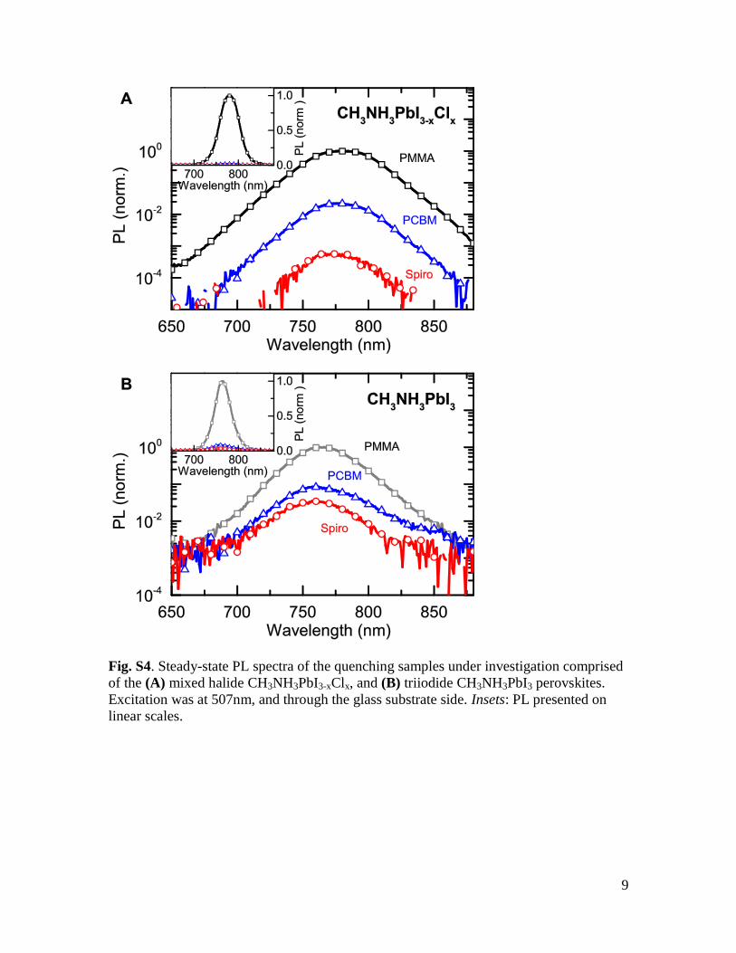
Fig. S4. Steady-state PL spectra of the quenching samples under investigation comprised
of the (A) mixed halide CH3NH3PbI3-xClx, and (B) triiodide CH3NH3PbI3 perovskites.
Excitation was at 507nm, and through the glass substrate side. Insets: PL presented on
linear scales.

10
Table S1. Table showing average device performance parameters extracted from current-
voltage characteristics for a batch of devices fabricated using the optimized protocols for
each perovskite. Devices were measured under 100mWcm-2
simulated AM1.5G
illumination. Errors represent the standard deviation in the batch.
Perovskite No. devices
Jsc (mAcm-2) Voc (V) Fill Factor PCE (%)
CH3NH3PbI3-xClx 9 13.1±4.3 0.89±0.10 0.59±0.14 7.8±4.0
CH3NH3PbI3 8 7.7±3.4 0.72±0.08 0.44±0.09 2.3±1.3
Table S2. Table summarizing the fitting parameters obtained from fits to the
photoluminescence data in Figure 2. τe is the time taken after excitation for the PL
intensity to drop to 1/e of the peak intensity, and τs and βs are parameters obtained from
stretched exponential fits to the PMMA data. The parameters and associated errors are
discussed in detail in the Materials and Methods section.
Perovskite Quencher τe (ns) τs (ns) βs
CH3NH3PbI3-xClx PMMA 272.65±6.95 285.7±11.7 0.833±0.032
PCBM 6.12±0.10 - - Spiro 5.12±0.06 - -
CH3NH3PbI3 PMMA 9.60±0.26 8.00±0.33 0.767±0.025 PCBM 3.17±0.03 - -
Spiro 4.22±0.06 - -
Table S3. Table summarizing the parameters obtained from fits to the transient
absorption data in Figure 1C using functions of the form A1exp(-t/τ1) + A2exp(-t/τ2). We
note that the photobleach decay curve is presented in Figure 1C as normalized O.D.,
while the photoabsorption decay remains as O.D.
Feature A1 τ1 (ns) A2 τ2 (ns)
Photobleach (750nm)
0.904±0.006 283.0±5.8 0.201±0.007 2337.7±117.3
Photoabsorption (550nm)
0.0074±0.0001 288.0±11.6 0.0049±0.0002 5863.9±698.4

References and Notes 1. S. Chu, A. Majumdar, Opportunities and challenges for a sustainable energy future. Nature
488, 294–303 (2012). doi:10.1038/nature11475 Medline
2. B. O'Regan, M. Gratzel, A low-cost, high-efficiency solar cell based on dye-sensitized colloidal TiO2 films. Nature 353, 737–740 (1991). doi:10.1038/353737a0
3. Z. He, C. Zhong, S. Su, M. Xu, H. Wu, Y. Cao, Enhanced power-conversion efficiency in polymer solar cells using an inverted device structure. Nat. Photonics 6, 593 (2012). doi:10.1038/nphoton.2012.190
4. R. A. J. Janssen, J. Nelson, Factors limiting device efficiency in organic photovoltaics. Adv. Mater. 25, 1847–1858 (2013). doi:10.1002/adma.201202873 Medline
5. T. Todorov, D. B. Mitzi, Direct liquid coating of chalcopyrite light-absorbing layers for photovoltaic devices. Eur. J. Inorg. Chem. 2010, 17–28 (2010). doi:10.1002/ejic.200900837
6. E. H. Sargent, Colloidal quantum dot solar cells. Nat. Photonics 6, 133–135 (2012). doi:10.1038/nphoton.2012.33
7. M. Graetzel, R. A. J. Janssen, D. B. Mitzi, E. H. Sargent, Materials interface engineering for solution-processed photovoltaics. Nature 488, 304–312 (2012). doi:10.1038/nature11476 Medline
8. G. Hodes, D. Cahen, All-solid-state, semiconductor-sensitized nanoporous solar cells. Acc. Chem. Res. 45, 705–713 (2012). doi:10.1021/ar200219h Medline
9. G. Yu, J. Gao, J. C. Hummelen, F. Wudl, A. J. Heeger, Polymer photovoltaic cells: Enhanced efficiencies via a network of internal donor-acceptor heterojunctions. Science 270, 1789–1791 (1995). doi:10.1126/science.270.5243.1789
10. O. V. Mikhnenko, H. Azimi, M. Scharber, M. Morana, P. W. M. Blom, M. A. Loi, Exciton diffusion length in narrow bandgap polymers. Energy Environ. Sci. 5, 6960 (2012). doi:10.1039/c2ee03466b
11. J. J. M. Halls, C. A. Walsh, N. C. Greenham, E. A. Marseglia, R. H. Friend, S. C. Moratti, A. B. Holmes, Efficient photodiodes from interpenetrating polymer networks. Nature 376, 498–500 (1995). doi:10.1038/376498a0
12. M. M. Lee, J. Teuscher, T. Miyasaka, T. N. Murakami, H. J. Snaith, Efficient hybrid solar cells based on meso-superstructured organometal halide perovskites. Science 338, 643–647 (2012). doi:10.1126/science.1228604
13. H.-S. Kim, C. R. Lee, J. H. Im, K. B. Lee, T. Moehl, A. Marchioro, S. J. Moon, R. Humphry-Baker, J. H. Yum, J. E. Moser, M. Grätzel, N. G. Park, Lead iodide perovskite sensitized all-solid-state submicron thin film mesoscopic solar cell with efficiency exceeding 9%. Sci. Rep. 2, 591 (2012). doi:10.1038/srep00591 Medline
14. J. H. Heo, S. H. Im, J. H. Noh, T. N. Mandal, C.-S. Lim, J. A. Chang, Y. H. Lee, H.- Kim, A. Sarkar, M. K. Nazeeruddin, M. Grätzel, S. I. Seok, Efficient inorganic-organic hybrid heterojunction solar cells containing perovskite compound and polymeric hole conductors. Nat. Photonics 7, 486 (2013). doi:10.1038/nphoton.2013.80

15. J. H. Noh, S. H. Im, J. H. Heo, T. N. Mandal, S. I. Seok, Chemical management for colorful, efficient, and stable inorganic-organic hybrid nanostructured solar cells. Nano Lett. 13, 1764–1769 (2013). Medline
16. J. M. Ball, M. M. Lee, A. Hey, H. J. Snaith, Low-temperature processed meso-superstructured to thin-film perovskite solar cells. Energy Environ. Sci. 6, 1739 (2013). doi:10.1039/c3ee40810h
17. J. Burschka, N. Pellet, S. J. Moon, R. Humphry-Baker, P. Gao, M. K. Nazeeruddin, M. Grätzel, Sequential deposition as a route to high-performance perovskite-sensitized solar cells. Nature 499, 316–319 (2013). doi:10.1038/nature12340 Medline
18. A. Abrusci, S. D. Stranks, P. Docampo, H. L. Yip, A. K. Jen, H. J. Snaith, High performance perovskite-polymer hybrid solar cells via electronic coupling with fullerene monolayers. Nano Lett. 13, 3124–3128 (2013). doi:10.1021/nl401044q Medline
19. M. Liu, M. B. Johnston, H. J. Snaith, Efficient planar heterojunction perovskite solar cells by vapour deposition. Nature 501, 395–398 (2013). doi:10.1038/nature12509 Medline
20. W. Zhang, M. Saliba, S. D. Stranks, Y. Sun, X. Shi, U. Wiesner, H. J. Snaith, Enhancement of perovskite-based solar cells employing core-shell metal nanoparticles. Nano Lett. 13, 4505–4510 (2013). doi:10.1021/nl4024287 Medline
21. A. Kojima, K. Teshima, Y. Shirai, T. Miyasaka, Organometal halide perovskites as visible-light sensitizers for photovoltaic cells. J. Am. Chem. Soc. 131, 6050–6051 (2009). doi:10.1021/ja809598r Medline
22. P. E. Shaw, A. Ruseckas, I. D. W. Samuel, Exciton diffusion measurements in poly(3-hexylthiophene). Adv. Mater. 20, 3516–3520 (2008). doi:10.1002/adma.200800982
23. T. Ishihara, Optical properties of PbI-based perovskite structures. J. Lumin. 60-61, 269–274 (1994). doi:10.1016/0022-2313(94)90145-7
24. K. Tanaka, T. Takahashi, T. Ban, T. Kondo, K. Uchida, N. Miura, Comparative study on the excitons in lead-halide-based perovskite-type crystals CH3NH3PbBr3 CH3NH3PbI3. Solid State Commun. 127, 619–623 (2003). doi:10.1016/S0038-1098(03)00566-0
25. M. Hirasawa, T. Ishihara, T. Goto, K. Uchida, N. Miura, Magnetoabsorption of the lowest exciton in perovskite-type compound (CH3NH3)PbI3. Physica B 201, 427–430 (1994). doi:10.1016/0921-4526(94)91130-4
26. G. E. Eperon, V. M. Burlakov, P. Docampo, A. Goriely, H. J. Snaith, Morphological control for high performance, solution-processed planar heterojunction perovskite solar cells. Advanced Funtional Materials, published online 9 September 2013 (10.1002/adfm.201302090).
27. J. R. Lakowicz, Principles of Fluorescence Spectroscopy (Springer London, Limited, 2007).