
Supplementary instructions: PROFIBUS® DP, …€“ Activating/deactivating remote configuration. n...
24
DULCOMETER ® Multi-parameter Controller diaLog DACa Supplementary instructions: PROFIBUS ® DP A1111 EN Target group: trained electronics technician 983739 BA DM 211 12/15 EN Please carefully read these operating instructions before use. · Do not discard. The operator shall be liable for any damage caused by installation or operating errors. The latest version of the operating instructions are available on our homepage.
Transcript of Supplementary instructions: PROFIBUS® DP, …€“ Activating/deactivating remote configuration. n...

DULCOMETER®
Multi-parameter Controller diaLog DACa
Supplementary instructions: PROFIBUS® DP
A1111
EN
Target group: trained electronics technician983739 BA DM 211 12/15 EN
Please carefully read these operating instructions before use. · Do not discard.The operator shall be liable for any damage caused by installation or operating errors.
The latest version of the operating instructions are available on our homepage.

In order to make it easier to read, this document uses the maleform in grammatical structures but with an implied neutral sense. Itis aimed equally at both men and women. We kindly ask femalereaders for their understanding in this simplification of the text.
Please read the supplementary information in its entirety.Information
This provides important information relating to the cor‐rect operation of the unit or is intended to make yourwork easier.
Safety InformationThe safety notes include detailed descriptions of the hazardous sit‐uation.The following symbols are used to highlight instructions, links, lists,results and other elements in this document:
More symbols
Symbol Description
Action, step by step
⇨ Outcome of an action
Links to elements or sections of these instructions or other applicable documents
n List without set order
[Taster] Display element (e.g. indicators)Operating element (e.g. button, switch)
‘Display /GUI’ Screen elements (e.g. buttons, assignment of function keys)
CODE Presentation of software elements and/or texts
General non-discriminatory approach
Supplementary information
Supplemental instructions
2
Table of contents1 Supplementary instructions PROFIBUS® DP....................... 4
1.1 Prerequisites................................................................. 41.2 Adjusting the controller................................................. 41.2.1 General...................................................................... 41.2.2 Configuring the PROFIBUS® DP............................... 41.3 Special features in active PROFIBUS® DP operation... 51.3.1 General...................................................................... 51.3.2 Display....................................................................... 51.3.3 LEDs on the PROFIBUS® DP module....................... 61.4 Installation..................................................................... 61.5 Operation...................................................................... 81.5.1 General...................................................................... 81.5.2 GSD file..................................................................... 81.5.3 Description of the data objects DACa........................ 91.6 Bit field definitions....................................................... 161.6.1 Status of the channel............................................... 161.6.2 Error of the channel................................................. 171.6.3 Warning of the channel............................................ 181.6.4 Potential-free relay................................................... 191.6.5 Settings of the channel configuration....................... 201.7 Diagnostic messages.................................................. 21
Table of contents
3

1 Supplementary instructions PROFIBUS® DP1.1 Prerequisites
Personnel must be familiar with the contents of the "Assembly andOperating Instructions for DULCOMETER® Multi-parameter Con‐troller diaLog DACa".
The controller must have a PROFIBUS® DP Module.
These supplementary instructions are only valid in combinationwith the operating instructions for the Multi-parameter ControllerdiaLog DACa.
1.2 Adjusting the controller1.2.1 General
The controller with PROFIBUS® DP functionality is adjusted in thesame way as the standard controller, with the addition of the busfunctionality.
Adjustment process cancelledIn the event of a pause longer than 60 s, the adjust‐ment process is cancelled.
1.2.2 Configuring the PROFIBUS® DPIn order to control the controller using the PROFIBUS® DP, youmust activate the PROFIBUS® DP in the controller operating menu(see the controller operating instructions).
While the PROFIBUS® DP is active, all external inputs will function.The external inputs lead to the expected reactions as in the case ofthe controller without PROFIBUS® DP functionality (see controlleroperating instructions). The controller sends corresponding infor‐mation over the PROFIBUS® DP to the master (PLC, PC etc.).Even if the fieldbus is set to inactive, the master is able to read-access the controller data defined in its GSD file.
If the PROFIBUS® DP is inactive or set to inactive, the settings forthe operating mode selected prior to "inactive" status are reloadedin the controller.If the controller is switched to another operating mode, it stops andcan only be restarted using the [Stop/Start] key.1. To access the ‘Menu’ : press the [Menu] key2. Use the cursor keys to select the menu item ‘Setup’ and
confirm with the [OK] key
ð The menu ‘Device setup’ appears.
Validity of the operating instructions
Supplementary instructions PROFIBUS® DP
4

3. Use the cursor keys to select the menu item ‘BusConfiguration ’ and confirm with the [OK] key
ð The ‘Configuration’ menu appears.
4. In the ‘Configuration’ menu, you can:n ‘Remote configuration’
– Activating/deactivating remote configuration.n ‘Address’
– Here you can set the address at which the controllerin the bus can be accessed.
n ‘Termination’– Here you can set whether the controller is the last
device in the bus and whether or not the terminatingresistance is activated.
1.3 Special features in active PROFIBUS® DP operation1.3.1 General
Setting and programmingIn PROFIBUS® DP operation, the controller cannot bemanually set or programmed. To set or programme thecontroller, set the PROFIBUS® DP to ‘inactive’ .
n When PROFIBUS® DP operation is selected, the settings fromthe last operating mode without PROFIBUS® DP are applied.By contrast, the settings made via the PROFIBUS® DP are notsaved. These only apply as long as the controller is linked tothe PROFIBUS® DP.
n If the controller is set to PROFIBUS® DP operation, it stops.The controller can be controlled again by pressing the [Stop/Start] key. The start command is given via the PRO‐FIBUS® DP module.
1.3.2 DisplayIn running PROFIBUS® DP operation there are further identifiers inthe operating indicator.
Common identifiersThe common identifiers are described in the controlleroperating instructions.
Supplementary instructions PROFIBUS® DP
5

1.3.3 LEDs on the PROFIBUS® DP module
Signal Cause
Off The module has no supply voltage or connection.
Green The module and the master are exchanging information.
Green flashing The module has been initialised.
Red flashing Error in pump parametrisation
Red flashing, double Error in PROFIBUS configuration
Signal Cause
Off The module has not been initialised.
Green The module has been initialised.
Green flashing The module has been initialised and there are diagnostic mes‐sages.
Red Serious exception error
1.4 InstallationAll devices that are members of the bus system, must be con‐nected in a line. There are up to 32 possible positions (master,slaves, repeaters).At both the beginning and end of the cable, the bus must be termi‐nated with a terminating resistance.
LED 1 (left) - module operating status
LED 2 (right) - module status
Bus installation
Supplementary instructions PROFIBUS® DP
6
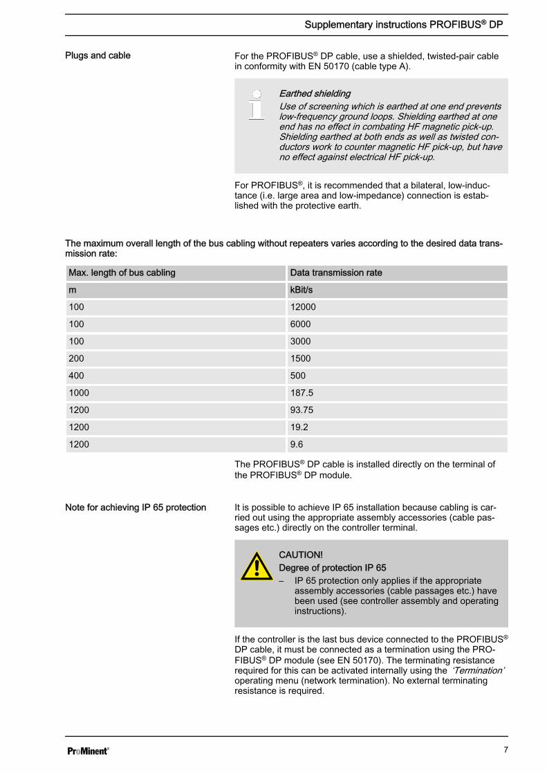
For the PROFIBUS® DP cable, use a shielded, twisted-pair cablein conformity with EN 50170 (cable type A).
Earthed shieldingUse of screening which is earthed at one end preventslow-frequency ground loops. Shielding earthed at oneend has no effect in combating HF magnetic pick-up.Shielding earthed at both ends as well as twisted con‐ductors work to counter magnetic HF pick-up, but haveno effect against electrical HF pick-up.
For PROFIBUS®, it is recommended that a bilateral, low-induc‐tance (i.e. large area and low-impedance) connection is estab‐lished with the protective earth.
The maximum overall length of the bus cabling without repeaters varies according to the desired data trans‐mission rate:
Max. length of bus cabling Data transmission rate
m kBit/s
100 12000
100 6000
100 3000
200 1500
400 500
1000 187.5
1200 93.75
1200 19.2
1200 9.6
The PROFIBUS® DP cable is installed directly on the terminal ofthe PROFIBUS® DP module.
It is possible to achieve IP 65 installation because cabling is car‐ried out using the appropriate assembly accessories (cable pas‐sages etc.) directly on the controller terminal.
CAUTION!Degree of protection IP 65– IP 65 protection only applies if the appropriate
assembly accessories (cable passages etc.) havebeen used (see controller assembly and operatinginstructions).
If the controller is the last bus device connected to the PROFIBUS®
DP cable, it must be connected as a termination using the PRO‐FIBUS® DP module (see EN 50170). The terminating resistancerequired for this can be activated internally using the ‘Termination’operating menu (network termination). No external terminatingresistance is required.
Plugs and cable
Note for achieving IP 65 protection
Supplementary instructions PROFIBUS® DP
7

Kommunikation Modul-PROFIBUS Kommunikation
Modul-LAN
optional: externer Anschluss Stecker M12x1 weiblich, 4-polig (D-codiert)
LAN-Netzwerk
Eingang Ausgang
Abschirm
ung
grün
rot Abschirm
ung
grün
rot
A1173
Fig. 1: Terminal diagram of the communication module
1.5 Operation1.5.1 General
Using the connected PROFIBUS® DP module, the PROFIBUS® DPcontroller represents a device with slave functionality in conformitywith DP V1. This means that the payload is transferred both cycli‐cally and acyclically.
1.5.2 GSD fileThe GSD file must be used for configuring the master. The GSDfile describes all of the features of the pump in PROFIBUS® DPoperation (keywords, diagnosis, modules, slots). The GSD file canbe downloaded from the PROFIBUS® website and from the ProMi‐nent website. The filename is clearly indicated: DACA0F4D.gsd .
Supplementary instructions PROFIBUS® DP
8

1.5.3 Description of the data objects DACaOutput data
Slot Index Name Module name Symbol Data type Bytecount
total:
Output data
Channel 1 ‘Channel 1’ 0xC0,0x80,0xC8
1 2 Measuredvalue
FLOAT 4
1 3 Controllercontrol var‐iable
INT16 2
1 4 Tempera‐ture
INT16 2 0.1 °C
1 5 Setpoint FLOAT 4
1 6 Externalinterfer‐ence vari‐able
UINT16 2 0.1 %
1 7 Channelstatus
UINT16 2 Ä Chapter1.6.1‘Status ofthe channel’on page 16
1 8 Warnings UINT16 2 Ä Chapter1.6.3‘Warning ofthe channel’on page 18
Channel 2 ‘Channel 2’ 0xC0,0x80,0xC8
2 2 Measuredvalue
FLOAT 4
2 3 Controllercontrol var‐iable
INT16 2
2 4 Tempera‐ture
UINT16 2 0.1 °C
2 5 Setpoint FLOAT 4
2 6 Externalinterfer‐ence vari‐able
UINT16 2 0.1 %
2 7 Channelstatus
UINT16 2 Ä Chapter1.6.1‘Status ofthe channel’on page 16
Supplementary instructions PROFIBUS® DP
9

Slot Index Name Module name Symbol Data type Bytecount
total:
2 8 Warnings UINT16 2 Ä Chapter1.6.3‘Warning ofthe channel’on page 18
Channel 3(differen‐tialchannel)
‘Channel 3’ 0x40,0xC3
3 1 Measuredvalue
FLOAT 4
3 2 Channelstatus
UINT16 2 Ä Chapter1.6.1‘Status ofthe channel’on page 16
3 3 Warnings UINT16 2 Ä Chapter1.6.3‘Warning ofthe channel’on page 18
mA output ‘mA Output’ 0x40,0xC2
4 1 Current(set) output1
UINT16 2 0.1 mA
4 2 Current(set) output2
UINT16 2 0.1 mA
4 3 Current(set) output3
UINT16 2 0.1 mA
Digitaloutput
‘digital output’ 0x40,0xC4
5 1 Relays UINT16 2 Ä Chapter1.6.4‘Potential-free relay’on page 19
5 2 MosFET 1 UINT16 2 Frequency
5 3 MosFET 2 UINT16 2 Frequency
5 4 MosFET 3 UINT16 2 Frequency
5 5 MosFET 4 UINT16 2 Frequency
Supplementary instructions PROFIBUS® DP
10
Slot Index Name Module name Symbol Data type Bytecount
total:
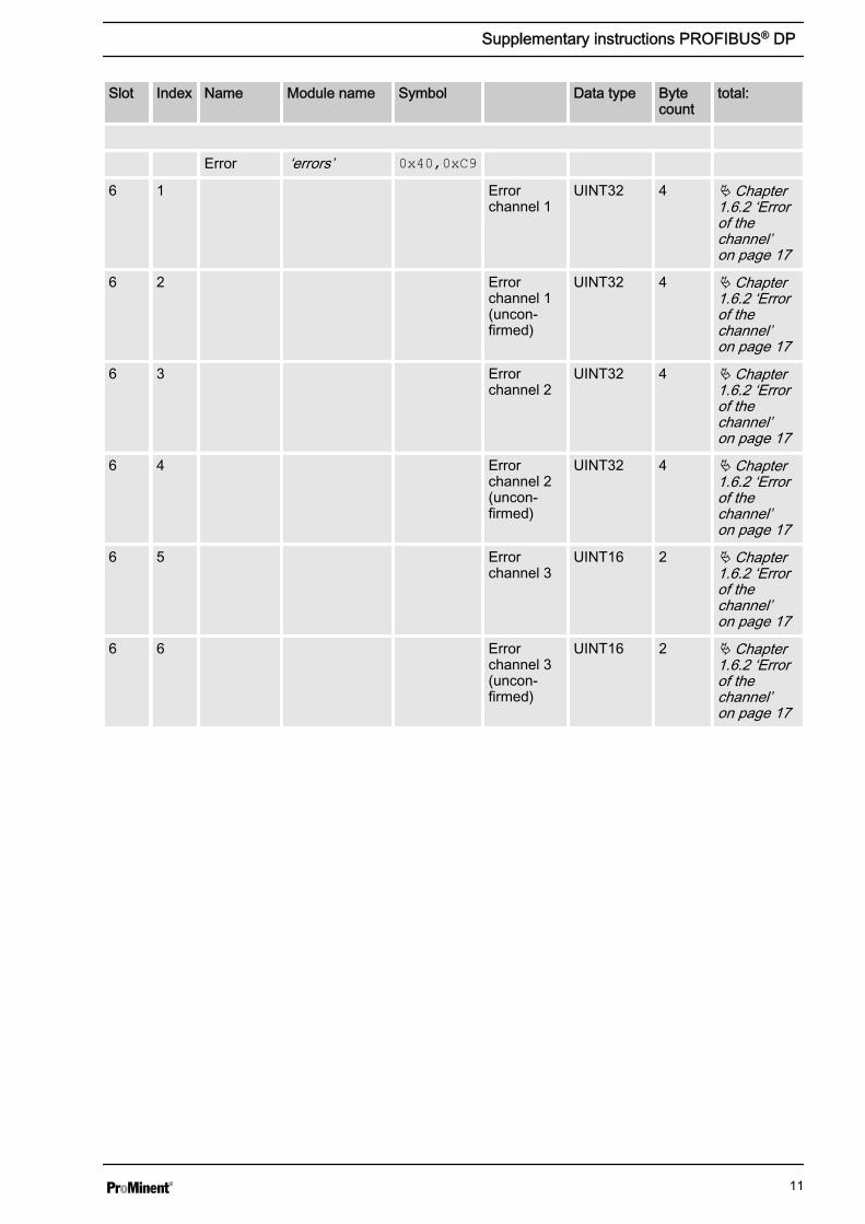
Error ‘errors’ 0x40,0xC9
6 1 Errorchannel 1
UINT32 4 Ä Chapter1.6.2 ‘Errorof thechannel’on page 17
6 2 Errorchannel 1(uncon‐firmed)
UINT32 4 Ä Chapter1.6.2 ‘Errorof thechannel’on page 17
6 3 Errorchannel 2
UINT32 4 Ä Chapter1.6.2 ‘Errorof thechannel’on page 17
6 4 Errorchannel 2(uncon‐firmed)
UINT32 4 Ä Chapter1.6.2 ‘Errorof thechannel’on page 17
6 5 Errorchannel 3
UINT16 2 Ä Chapter1.6.2 ‘Errorof thechannel’on page 17
6 6 Errorchannel 3(uncon‐firmed)
UINT16 2 Ä Chapter1.6.2 ‘Errorof thechannel’on page 17
Supplementary instructions PROFIBUS® DP
11
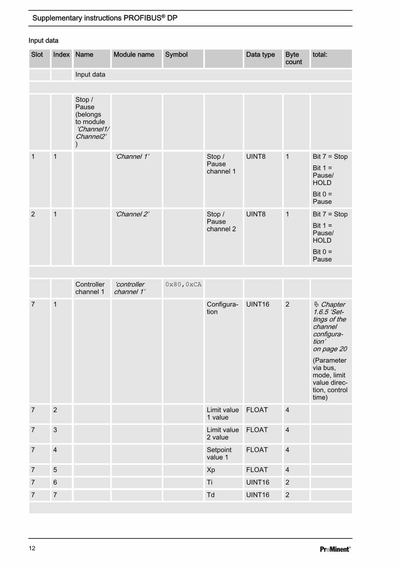
Input data
Slot Index Name Module name Symbol Data type Bytecount
total:
Input data
Stop /Pause(belongsto module‘Channel1/Channel2’)
1 1 ‘Channel 1’ Stop /Pausechannel 1
UINT8 1 Bit 7 = StopBit 1 =Pause/HOLDBit 0 =Pause
2 1 ‘Channel 2’ Stop /Pausechannel 2
UINT8 1 Bit 7 = StopBit 1 =Pause/HOLDBit 0 =Pause
Controllerchannel 1
‘controllerchannel 1’
0x80,0xCA
7 1 Configura‐tion
UINT16 2 Ä Chapter1.6.5 ‘Set‐tings of thechannelconfigura‐tion’on page 20(Parametervia bus,mode, limitvalue direc‐tion, controltime)
7 2 Limit value1 value
FLOAT 4
7 3 Limit value2 value
FLOAT 4
7 4 Setpointvalue 1
FLOAT 4
7 5 Xp FLOAT 4
7 6 Ti UINT16 2
7 7 Td UINT16 2
Supplementary instructions PROFIBUS® DP
12

Slot Index Name Module name Symbol Data type Bytecount
total:
Controllerchannel 2
‘controllerchannel 2’
0x80,0xCA
8 1 Configura‐tion
UINT16 2 Ä Chapter1.6.5 ‘Set‐tings of thechannelconfigura‐tion’on page 20(Parametervia bus,mode, limitvalue direc‐tion, controltime)
8 2 Limit value1 value
FLOAT 4
8 3 Limit value2 value
FLOAT 4
8 4 Setpoint 1 FLOAT 4
8 5 Xp FLOAT 4
8 6 Ti UINT16 2
8 7 Td UINT16 2
Controllerchannel 3
‘controllerchannel 3’
0x80,0xC4
9 1 Configura‐tion
UINT16 2 Ä Chapter1.6.5 ‘Set‐tings of thechannelconfigura‐tion’on page 20(e. g. limitvalue direc‐tion, controlstop in theevent oferror)
9 2 Limit value1 value
FLOAT 4
9 3 Limit value2 value
FLOAT 4
Error con‐firmation
‘errorconfirmation’
0x80,0xC4
Supplementary instructions PROFIBUS® DP
13

Slot Index Name Module name Symbol Data type Bytecount
total:
10 1 Errorchannel 1
UINT32 4 0xFFFFFFFF *=> allpendingerrors havebeen con‐firmedÄ Chapter1.6.2 ‘Errorof thechannel’on page 17
10 2 Errorchannel 2
UINT32 4 0xFFFFFFFF *=> allpendingerrors havebeen con‐firmedÄ Chapter1.6.2 ‘Errorof thechannel’on page 17
10 3 Errorchannel 3
UINT16 2 0xFFFF *=> allpendingerrors havebeen con‐firmedÄ Chapter1.6.2 ‘Errorof thechannel’on page 17
* These errors can also be deleted/confirmed individually.
Acyclic data
Controllerparameterchannel 1
‘controllerparameter ch1’
11 1 Additivebasic load
INT16 2
11 2 Controlvariablelimitation
UINT16 2
11 3 Delay afterstop
UINT16 2
11 4 Delay afterrestart
UINT16 2
Supplementary instructions PROFIBUS® DP
14

Slot Index Name Module name Symbol Data type Bytecount
total:
11 5 Setpoint 2 FLOAT 4 only withneutral zonecontrol
Controllerparameterchannel 2
‘controllerparameter ch2’
0x80,0xC5
12 1 Additivebasic load
INT16 2
12 2 Controlvariablelimitation
UINT16 2
12 3 Delay afterstop
UINT16 2
12 4 Delay afterrestart
UINT16 2
12 5 Setpoint 2 FLOAT 4 only withneutral zonecontrol
Deviceinforma‐tion
‘deviceinformation’
0x40,0xC7
13 1 Firmware UINT32 4 In hexadec‐imal format
13 2 FirmwareIOS
UINT32 4 In hexadec‐imal format
13 3 Deviceserialnumber
UINT32 4 In hexadec‐imal format
13 4 Revision UINT16 2 In hexadec‐imal format
13 5 RevisionIOS
UINT16 2 In hexadec‐imal format
Identitycode
‘identity code’ 0x40,0xCB
14 1 Identitycode0-3
UINT32 4
14 2 Identitycode4-7
UINT32 4
14 3 Identitycode8-11
UINT32 4
Supplementary instructions PROFIBUS® DP
15

Slot Index Name Module name Symbol Data type Bytecount
total:
14 4 Identitycode12-15
UINT32 4
14 5 Identitycode16-20
UINT32 4
14 6 Identitycode21-24
UINT32 4
1.6 Bit field definitions1.6.1 Status of the channelBit Description
15 1 = channel uses bus control parameters; 0 = channel uses internal parameters
14
13 1 = error exists; 0 = no error
12 1 = warning exists; 0 = no warning
11 1 = SD card full; 0 = SD card not full
10 1 = SD card free < 20%; 0 = SD card free ≧ 20%
9 1 = SD card exists; 0 = no SD card
8 1 = local control rate 2 active; 0 = local control rate 1 active
7
6
5
4
3
2
1 1 = local stop active; 0 = no local stop active
0 1 = channel active; 0 = channel inactive (or cannot be connected)
Supplementary instructions PROFIBUS® DP
16

1.6.2 Error of the channelBit Description
31 Error 99: There is a system error;[A system error exists]
30
29
28
27
26
25
24
23
22
21
20 Error 88: The connection to the extension module is faulty;[The connection to the expansion module is faulty ]
19 Error 34: Incorrect correction variable; [Incorrect correction variable ]
18 Error 19: The liquid level in storage tank 3 is too low; [The level in tank 3 is too low ]
17 Error 18: The liquid level in storage tank 2 is too low; [The level in tank 2 is too low ]
16 Error 17: The liquid level in storage tank 1 is too low; [The level in tank 1 is too low ]
15 Error 16: The mA input is overloaded; [The mA input is overloaded]
14 Error 15: The mA input supply is overloaded; [The mA input supply is overloaded]
13 Error 14: The status of the controller is pause / hold [PAUSE / HOLD];[The controller is in the state PAUSE / HOLD]
12 Error 13: The status of the controller is pause [PAUSE]; [The controller is in the state PAUSE]
11 Error 12: There is a sample water fault e.g. no flow; [Error sample water exists, e. g. no flow]
10 Error 11: After elapse of the delay period, a limit value error still exists;[After elapsing of the delay time a limit error still exists]
9 Error 10: The mA input current is less than 4 mA; [The mA input current is less than 4 mA ]
8 Error 9: The mA input current is greater than 20 mA;[The mA input current is greater than 20 mA ]
7 Error 8: The check time was infringed; [The checkout time was infringed]
6 Error 7: Check the mechanical condition (glass breakage) of the sensor;[Check the mechanical status of the sensor Glass break is possible]
5 Error 6: No sensor available; [No sensor is available ]
4 Error 5: Calibration error exists; [A calibration error exists]
3 Error 4: The temperature is too high; [The temperature is too high]
2 Error 3: The temperature is too low; [The temperature is too low ]
1 Error 2: The mV input voltage is too high; [The mV input voltage is too high ]
0 Error 1: The mV input voltage is too low; [The mV input voltage is too low ]
Supplementary instructions PROFIBUS® DP
17
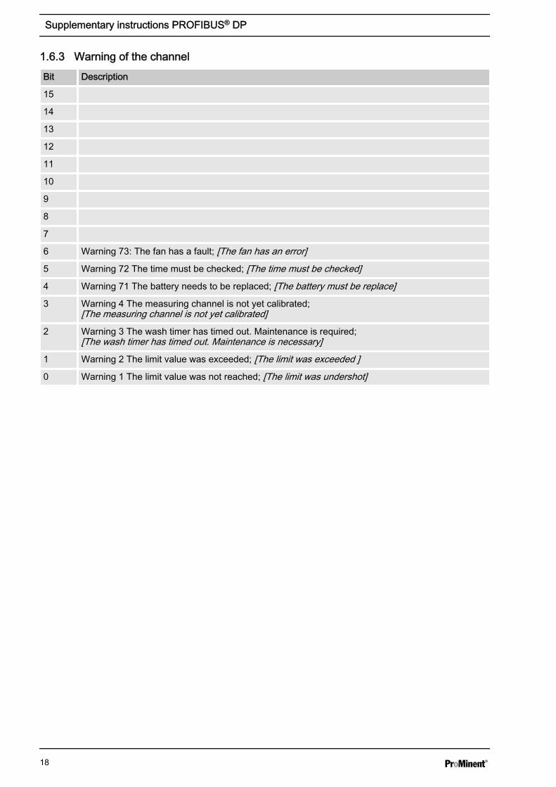
1.6.3 Warning of the channelBit Description
15
14
13
12
11
10
9
8
7
6 Warning 73: The fan has a fault; [The fan has an error]
5 Warning 72 The time must be checked; [The time must be checked]
4 Warning 71 The battery needs to be replaced; [The battery must be replace]
3 Warning 4 The measuring channel is not yet calibrated;[The measuring channel is not yet calibrated]
2 Warning 3 The wash timer has timed out. Maintenance is required;[The wash timer has timed out. Maintenance is necessary]
1 Warning 2 The limit value was exceeded; [The limit was exceeded ]
0 Warning 1 The limit value was not reached; [The limit was undershot]
Supplementary instructions PROFIBUS® DP
18
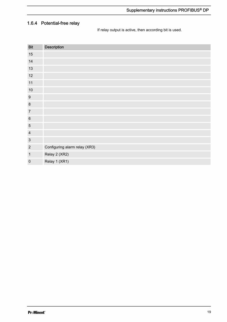
1.6.4 Potential-free relayIf relay output is active, then according bit is used.
Bit Description
15
14
13
12
11
10
9
8
7
6
5
4
3
2 Configuring alarm relay (XR3)
1 Relay 2 (XR2)
0 Relay 1 (XR1)
Supplementary instructions PROFIBUS® DP
19
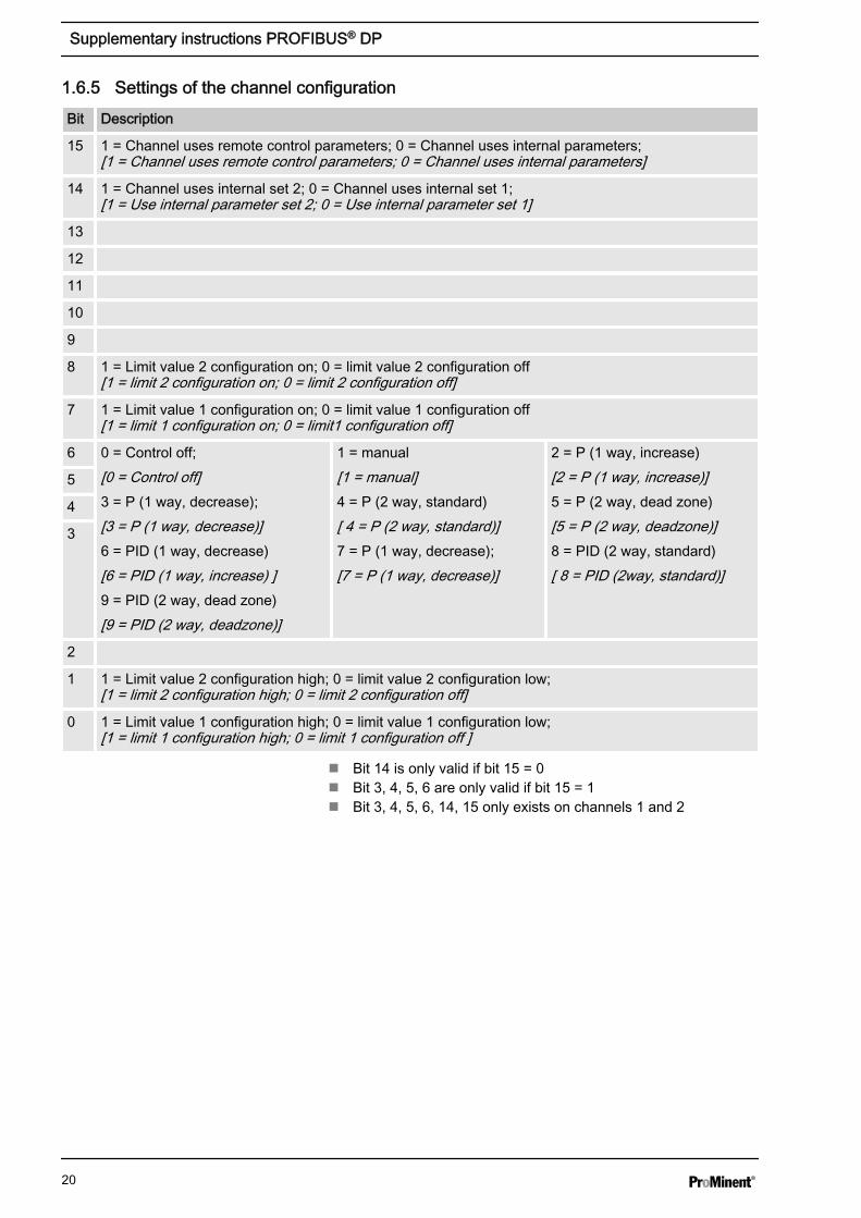
1.6.5 Settings of the channel configurationBit Description
15 1 = Channel uses remote control parameters; 0 = Channel uses internal parameters;[1 = Channel uses remote control parameters; 0 = Channel uses internal parameters]
14 1 = Channel uses internal set 2; 0 = Channel uses internal set 1;[1 = Use internal parameter set 2; 0 = Use internal parameter set 1]
13
12
11
10
9
8 1 = Limit value 2 configuration on; 0 = limit value 2 configuration off[1 = limit 2 configuration on; 0 = limit 2 configuration off]
7 1 = Limit value 1 configuration on; 0 = limit value 1 configuration off[1 = limit 1 configuration on; 0 = limit1 configuration off]
6 0 = Control off;[0 = Control off]3 = P (1 way, decrease);[3 = P (1 way, decrease)]6 = PID (1 way, decrease)[6 = PID (1 way, increase) ]9 = PID (2 way, dead zone)[9 = PID (2 way, deadzone)]
1 = manual[1 = manual]4 = P (2 way, standard)[ 4 = P (2 way, standard)]7 = P (1 way, decrease);[7 = P (1 way, decrease)]
2 = P (1 way, increase)[2 = P (1 way, increase)]5 = P (2 way, dead zone)[5 = P (2 way, deadzone)]8 = PID (2 way, standard)[ 8 = PID (2way, standard)]
5
4
3
2
1 1 = Limit value 2 configuration high; 0 = limit value 2 configuration low;[1 = limit 2 configuration high; 0 = limit 2 configuration off]
0 1 = Limit value 1 configuration high; 0 = limit value 1 configuration low;[1 = limit 1 configuration high; 0 = limit 1 configuration off ]
n Bit 14 is only valid if bit 15 = 0n Bit 3, 4, 5, 6 are only valid if bit 15 = 1n Bit 3, 4, 5, 6, 14, 15 only exists on channels 1 and 2
Supplementary instructions PROFIBUS® DP
20

1.7 Diagnostic messagesIn conformity with PROFIBUS® standard, the device makes theGet_Sl_Diag service available. The diagnostics data comprisestandard diagnostics information (6-Bytes according to PRO‐FIBUS® standard) and any possible diagnostics data specific to thedevice. A maximum of 63 bytes can be inserted for the device-spe‐cific diagnostics data. The first 4 bytes in the PROFIBUS® standardare specified from this:
Evaluate the byte sign_len as follows:
Length of the DU status including the header byte: 04..63Flags ‘device-related diagnostics’: 00 constant
Evaluate the byte status_type as follows:
Status type: 48 (manufacturer specific)Flags ‘Status’: 1 constant
Evaluate the byte slot_number as follows:
Slot number: 0 (because only slot 0 is being used)
Evaluate the byte specifier as follows:
Status specification: 00 constantReserved
59 bytes subsequently remain freely available (user_data):
Errors are indicated using the user_data fields.The user_data fields are each combined in blocks of 3 bytes andare interpreted as follows:1 - Service2 - Error type3 - Type of data access (read/write)
Thus up to 19 errors can be signalled.
Diagnostic telegrams
0 0
1 0 1 1 0 0 0 0
0 0 0 0 0 0 0 0
0 0
user_data
Supplementary instructions PROFIBUS® DP
21

Order Number Name
1 CHANNEL_1 STOP
2 CHANNEL_1 MEASUREMENT_VALUE
3 CHANNEL_1 CONTROLLER_VALUE
4 CHANNEL_1 TEMPERATURE
5 CHANNEL_1 SET_POINT
6 CHANNEL_1 DISTURBANCE
7 CHANNEL_1 STATES
8 CHANNEL_1 WARNINGS
21 CHANNEL_2 STOP
22 CHANNEL_2 MEASUREMENT_VALUE
23 CHANNEL_2 CONTROLLER_VALUE
24 CHANNEL_2 TEMPERATURE
25 CHANNEL_2 SET_POINT
26 CHANNEL_2 DISTURBANCE
27 CHANNEL_2 STATES
28 CHANNEL_2 WARNINGS
31 CHANNEL_3 STOP
32 CHANNEL_3 STATES
33 CHANNEL_3 WARNINGS
41 MA_OUTPUT_1
42 MA_OUTPUT_2
43 MA_OUTPUT_3
51 RELAY
52 PUMP_RELAY_1
53 PUMP_RELAY_2
54 PUMP_RELAY_3
55 PUMP_RELAY_4
61 CHANNEL_1 ERRORS_EXISTS
62 CHANNEL_1 ERRORS_NOTACKS
63 CHANNEL_2 ERRORS_EXISTS
64 CHANNEL_2 ERRORS_NOTACKS
65 CHANNEL_3 ERRORS_EXISTS
66 CHANNEL_3 ERRORS_NOTACKS
71 CHANNEL_1 REMOTE_CONFIGURATION
72 CHANNEL_1 REMOTE_LIMIT1
73 CHANNEL_1 REMOTE_LIMIT2
74 CHANNEL_1 REMOTE_SET_POINT
Encoding user_data
Supplementary instructions PROFIBUS® DP
22

Order Number Name
75 CHANNEL_1 REMOTE_XP
76 CHANNEL_1 REMOTE_TI
77 CHANNEL_1 REMOTE_TD
81 CHANNEL_2 REMOTE_CONFIGURATION
82 CHANNEL_2 REMOTE_LIMIT1
83 CHANNEL_2 REMOTE_LIMIT2
84 CHANNEL_2 REMOTE_SET_POINT
85 CHANNEL_2 REMOTE_XP
86 CHANNEL_2 REMOTE_TI
87 CHANNEL_2 REMOTE_TD
91 CHANNEL_3 REMOTE_CONFIGURATION
92 CHANNEL_3 REMOTE_LIMIT1
93 CHANNEL_3 REMOTE_LIMIT2
101 CHANNEL_1 ERROR_CONFIRMATION
102 CHANNEL_2 ERROR_CONFIRMATION
103 CHANNEL_3 ERROR_CONFIRMATION
Error type
Value Meaning
0x30 OK -
0x31 Transfer OK Date outside of permitted range
0x32 Transfer OK Date protected
0x33 Transfer OK Date rejected, due to device in manual and not in remoteoperation
0x34 Transfer OK Date rejected, due to uninstalled option
0x35 Transfer OK Service not defined
0x36 Transfer OK Value cannot be read or changed in current device context
0x37 Transfer OK No further updating
0x55 Transfer OK Fuse / UART error
0x56 Error in timeout -
Type of data access (read/write)
Value Meaning
0xD3 Write access
0xE5 Read access
Supplementary instructions PROFIBUS® DP
23

983739, 1, en_GB
© 2015
ProMinent GmbHIm Schuhmachergewann 5 - 1169123 HeidelbergGermanyTelephone: +49 6221 842-0Fax: +49 6221 842-419Email: [email protected]: www.prominent.com


![DEACTIVATING ACTAVIS THE CLASH BETWEEN THE SUPREME … · 2015] DEACTIVATING ACTAVIS 559 Actavis.6 The drug manufacturers could in effect use patent rights, however weak, as the pretext](https://static.fdocuments.net/doc/165x107/5f1fcea8abcc044e1721b843/deactivating-actavis-the-clash-between-the-supreme-2015-deactivating-actavis-559.jpg)


