
Supplementary information to the WSAA Sewage … to the... · Supplementary information to the WSAA...
21
Supplementary information to the WSAA Sewage Pumping Station Code of Australia WSA 04-2005 Version 2.1
Transcript of Supplementary information to the WSAA Sewage … to the... · Supplementary information to the WSAA...

Supplementary information to the WSAA Sewage Pumping Station Code of Australia
WSA 04-2005
Version 2.1

1
Table of contents
1. General .............................................................................................................................. 5
1.2.2 Pumping alternatives ................................................................................................. 5
1.5.2 Planning responsibilities ............................................................................................ 5
1.6.3 Objectives of design .................................................................................................. 5
2. Concept design ................................................................................................................. 5
2.2 Functionality ................................................................................................................ 5
2.3 Maintainability ............................................................................................................. 5
2.5 Due diligence requirements ......................................................................................... 6
2.9 Odour control .............................................................................................................. 6
2.11 Services ....................................................................................................................... 6
2.14 Signage....................................................................................................................... 6
2.17 Commissioning plan ................................................................................................... 6
2.17.3 Commissioning ........................................................................................................ 6
3. General design .................................................................................................................. 7
3.1 General ......................................................................................................................... 7
4. Materials design ............................................................................................................... 7
4.2 Corrosion protection ................................................................................................... 7
4.2.1 Protective coatings .................................................................................................... 7
4.2.2 Concrete surfaces ..................................................................................................... 7
4.2.3 Metallic materials ...................................................................................................... 7
5. Pumping Station Design .................................................................................................... 7
5.1 Introduction ................................................................................................................. 7
5.2.1 Site selection ............................................................................................................. 7
5.2.3 Location and layout ................................................................................................... 7
5.2.4 Site area .................................................................................................................... 8
5.2.5 Site layout and access ................................................................................................ 8
5.3.3 Pumping station wet-well isolating valve ................................................................... 8
5.4.1 General ...................................................................................................................... 8
5.4.2 Sizing ........................................................................................................................ 8
5.4.4 Control levels ............................................................................................................ 8
5.4.7 Washers ..................................................................................................................... 8
5.5.2 Forced ventilation ..................................................................................................... 9
5.6.1 General ...................................................................................................................... 9
5.7 Ladders and platforms .................................................................................................. 9
5.9 Safety systems .............................................................................................................. 9
5.11 Screens ........................................................................................................................ 9

2
5.12 Mixers ......................................................................................................................... 9
6. Pumping system ............................................................................................................. 10
6.4 Pump selection .......................................................................................................... 10
6.6.3 Motor selection ...................................................................................................... 10
6.6.5 Junction boxes ........................................................................................................ 10
6.8 Pump starters and variable speed drives .................................................................... 10
6.8.3 Soft starters............................................................................................................. 10
6.8.4 Variable speed drives .............................................................................................. 10
7. Power system .................................................................................................................. 10
7.1 General ....................................................................................................................... 10
7.2.3 Primary supply ......................................................................................................... 10
7.3.3 Meter requirements ................................................................................................ 10
7.3.4 Lighting ................................................................................................................... 10
8. Control and telemetry system ......................................................................................... 11
8.1 General ........................................................................................................................ 11
8.3.1 Control design .......................................................................................................... 11
8.3.4 Emergency back–up control.................................................................................... 11
8.3.5 Pump starts and interlocks ....................................................................................... 11
8.5.3 Alarm creation function............................................................................................ 11
8.6.1 General ..................................................................................................................... 12
8.6.2 Software ................................................................................................................... 12
8.6.3 Inputs and outputs ................................................................................................... 12
8.6.4 Telemetry communications ..................................................................................... 12
8.6.5 Communication validation ....................................................................................... 12
8.8.1 General ..................................................................................................................... 12
8.8.2 Flow measurement ................................................................................................... 13
8.8.5 Level sensors ............................................................................................................ 13
8.8.6 Float-switch ............................................................................................................. 13
8.10 Wire numbering convention ..................................................................................... 13
8.11.1 Digital inputs and outputs ........................................................................................ 13
8.11.2 Analog inputs and outputs ...................................................................................... 13
8.12.1 General .................................................................................................................... 13
8.12.2 Loop tag definition guidelines ................................................................................ 13
9. Wet-well pipework .......................................................................................................... 13
9.1.2 Sizing ........................................................................................................................ 13
9.1.3 Type.......................................................................................................................... 14
9.2.3 Scour/Emergency by-pass connection..................................................................... 14
9.2.4 Sewage air-release valves ......................................................................................... 14

3
9.3.1 General ..................................................................................................................... 14
9.3.2 Design ...................................................................................................................... 14
9.3.3 Dismantling joints .................................................................................................... 14
9.4.1 Condition monitoring and maintenance .................................................................. 14
10. Pressure main ................................................................................................................. 14
10.1.1 General .................................................................................................................... 14
10.2.2 Road reserves ......................................................................................................... 15
10.3 Hydraulic design ........................................................................................................ 15
10.4.3 Surge ...................................................................................................................... 15
10.9.2 Isolating valves ....................................................................................................... 15
10.9.3 Gas release valves ................................................................................................... 15
10.9.5 Scours..................................................................................................................... 15
10.10 Odour and septicity control..................................................................................... 15
10.11.1 General ................................................................................................................... 15
10.11.2 Discharge manholes .............................................................................................. 15
11. Structural design ............................................................................................................. 16
11.2.5 Pumping station walls .............................................................................................. 16
11.3.2 Products and materials ............................................................................................ 16
11.3.4.2 Pipe cover ............................................................................................................. 16
12. Supporting systems ........................................................................................................ 16
12.1.3 Telephone/Telemetry lines ...................................................................................... 16
12.3 Security ...................................................................................................................... 16
12.4 Fire control ................................................................................................................ 16
13. Health and safety ............................................................................................................ 17
13.1 General ....................................................................................................................... 17
13.4 Confined spaces ........................................................................................................ 17
15. Design documentation and drawings ............................................................................. 17
Appendix A .......................................................................................................................... 19
Appendix B .......................................................................................................................... 20
4
Introduction Barwon Water’s design and constructions requirements for sewerage pumping systems required for land development works is the Water Services Association of Australia Sewage Pumping Station Code of Australia WSA 04-2005 Version 2.1 with the exceptions listed in this supplement.
General These clauses are to be read in conjunction with the WSAA Sewage Pumping Station Code of Australia WSA 04-2005. Where there is conflict between the code and these clauses, these clauses shall take precedence.
The designer should seek clarification from Barwon Water if there is in any doubt about the wording or intention of these clauses.
Operation The clause numbering of this supplementary document matches the WSAA Code.
Innovative solutions WSAA Sewage Code of Australia and this supporting documentation essentially provides “deemed-to-comply” solutions for the creation of Water Agency Sewerage assets. Alternative solutions, practices, equipment and methodologies will continue to evolve and offer opportunities to improve the creation of these assets. Barwon Water encourages employment of any innovation that offers enhanced productivity and serviceability, but Barwon Water input should be sought before any innovative system is designed.
Responsibilities Designers and constructors are responsible for their respective aspects of the design and construction process. It is the designer/constructors responsibility to justify any variation from the requirements set out in the Sewage Code of Australia (including the attached Barwon Water conditions) and/or the Barwon Water Construction Drawings plus any specific directions given by Barwon Water for the particular project. The designer/constructor is to obtain Barwon Water endorsement for any variation.
Amendment history Update number Brief description Effective date
1.
1. Separation from Land Development Manual 2. Addition of amendment history section 3. Title page, headers/footers, page numbers and content page
updated 4. Removal of blank headings where no exceptions are relevant to the
WSAA code (reducing total pages from 69 to 43) Addition of Electrical Design Brief Appendix B – rather than separate document
June 2010
2.
1. 4.2.1 Protective coatings 2. 4.2.2 Concrete surfaces 3. 4.2.3 Metallic materials 4. 5.3.3 Pumping station wet-well isolation valve 5. 5.4.1 General 6. 5.4.7 Washers 7. 5.12 Mixers 8. 8.8.5 Level Sensors 9. 9.1.2 Sizing 10.11.2 Discharge Manholes
May 2013

5
1. General
1.2.2 Pumping alternatives
Barwon Water requires documentary evidence that the life-cycle cost of all options has been thoroughly assessed prior to approving construction of the pumping station.
1.5.2 Planning responsibilities
Present and future flows at the station are set at this stage.
1.6.3 Objectives of design
Compliance with environmental requirements means that all environmental requirements shall be met. These include but are not limited to noise, odour, visual aspects, erosion and landscaping. Evidence of compliance with these shall be provided prior to approval for construction.
2. Concept design
2.2 Functionality Replace item (f) with the following:
f. Provide safe working conditions for operation and maintenance
Personnel including a hard standing area adjacent to the pump
• station that has allowance for vehicular movements and access to the wet well, fall protection grids and safety railings.Peak wet weather flow shall be considered to be four times average dry weather flow.
• adequate pumping and storage capacity for attenuation of incoming flows during wet weather shall be provided to ensure containment of a 1 in 5 year Average Recurrence Interval (ARI) rainfall event coinciding with peak dry weather flow. Provision of an emergency storage to contain peak dry weather flow for the periods required in section 5.6.2.2 herein in the event of a pump station failure. Emergency relief shall comply with any sewer system overflow license requirements established by the environmental regulator.
• evidence that EPA requirements for noise and odour control are required.
• risk analysis shall be carried out to identify the likelihood of an overflow, how that can be limited and where it will occur.
2.3 Maintainability • Barwon Water regularly flushes out wet-wells. This is done from ladders and landings inside the
station. Ladders and landings are required.
• A by-pass pumping point is required.
• Barwon Water requires the flowmeter be housed within a watertight manhole with a sluice valve immediately downstream. The flow meter shall be installed with a gibault either side to allow changeability. The sluice valve will facilitate repairs or replacement of the flowmeter without having to drain the rising main. A suitable interchangeable section of pipe is to be provided, for insertion when the flowmeter is removed.
• Barwon Water has a criticality and condition assessment for pump station equipment that incorporates interchange ability. All components must suit this.

6
2.5 Due diligence requirements Contingency Plan • A contingency plan shall be submitted to and approved by Barwon Water
prior to construction commencing.
Environmental Impact Assessment
• Shall be done in accordance with Barwon Water’s Environmental Management System to ISO 14001 standard.
• The designer shall liaise with and comply with any sewerage system overflow licence requirements established by the EPA Victoria.
2.9 Odour control
The designer shall provide evidence that odour generation and control has been considered. The designer is required to provide calculations of detention times including gas phase Hydrogen Sulphide and dissolved sulphide generation within the wet-well and pressure main discharge point. Barwon Water will not accept any designs submitted without these calculations.
Detention times shall be based on ADWF.
2.11 Services
A secure (enclosed in an appropriate cage) potable water assembly is required with a certified backflow device and a 32mm tap to facilitate maintenance works at the station.
2.14 Signage
Signs identifying confined spaces shall be provided. The signs shall be located in a prominent position adjacent to the entry of the confined pace
2.17 Commissioning plan
The designer to submit one at the concept design stage.
2.17.3 Commissioning
Notification of intent to commission must be made to Barwon Water, 21 days in advance to ensure that electrics and telemetry functions are operational. Prior to commissioning, the station must be pre-commissioned in consultation with Barwon Water representatives to ensure that all alarms are being received via Barwon Water’s telemetry.
Pre-commissioning record sheets must be completed and lodged with Barwon Water, 10 working days prior to the planned commissioning date. Barwon Water representatives must attend the commissioning.
The pump station will not be commissioned / deemed operational until all documentation has been provided together with:
a.) Plant data sheets (two hard copies, one digital copy)
b.) As constructed drawings for Civil, Mechanical and Electrical (SPS & RM) (two hard copies, one digital)
c.) Three copies of the operational and maintenance manuals inclusive of pump system curves (two hard copies, one digital copy)
d.) Contingency Plan
e.) Switchboard factory and site acceptance test certificates completed and signed
f.) Any other documentation required by Barwon Water.

7
3. General design
3.1 General
The preferred pumps are Flygt or ABS. Other pumps will be considered on a case by case basis.
4. Materials design
4.2 Corrosion protection
4.2.1 Protective coatings
As a minimum, any protective coating proposed by contractors should be 2-3 mm thick (dry film), have 10 years warranty, and offer equivalent H2S protection as provided by Epigen 1311 or Tufflon Polyurea P90.
4.2.2 Concrete surfaces
Exposed concrete surfaces in the wet-well and valve chamber shall be coated with an epoxy lining system Eg. Tufflon Polyurea P90 / Epigen Epoxy Resin 1311 or approved equivalent.
4.2.3 Metallic materials
All exposed pipework and valves within the wet-well and valve chamber is to be coated with an approved epoxy lining system (as above).
Metal work within all pumping station structures shall be grade 316 stainless steel (grade 316L for fabricated items) unless dissimilar metal / galvanic corrosion is likely as a result of the stainless steel installation.
5. Pumping station design
5.1 Introduction Barwon Water will advise the designer of any agency requirements at the preliminary design stage.
Additional requirements may include those imposed by the council, EPA, DSE, Parks Victoria and interest groups. The designer shall be responsible for liaising with all stakeholders.
Barwon Water use a portable davit arm as an anchor point for life-lines used during confined space entry. The developer must provide a base suitable for use with this davit in the concrete top-slab. Barwon Water will provide specifications for this base on request.
5.2.1 Site selection
In all instances the designer shall prepare a plan for Barwon Water that addresses:
(a) Environmental Impacts (b) Buoyancy Affects
In most instances the designer will need to arrange for a borehole or a number of boreholes to be drilled at the proposed site.
5.2.3 Location and layout
The design of the access road to a pumping station shall reflect the size and operating requirements of the largest maintenance vehicle specified by Barwon Water required to access the site. The pumping station road turning area shall be sized to accommodate a 10 tonne truck.

8
5.2.4 Site area
Sufficient parking area shall be provided to accommodate two 10 tonne trucks. The parking area should be adjacent to the station to allow for access by crane trucks.
5.2.5 Site layout and access
The minimum turning radius around the station and access roads shall however be at least suitable for an 8.8 metre service vehicle as per Austroads Standards Australia – AS HB72. The vehicle must be able to be parked with the rear or side of the vehicle next to the well.
Access road grades steeper than 2% shall be cement stabilised, and roads steeper than 5% must be sealed. In areas where the station is at the end of a dead-end access, the hardstand must allow for the truck to be turned around within the pavement area.
The average grade of roads must be no more than 1 in 7 (14.4%) with a maximum of no more than 1 in 5 (20%) for more than 50 metres. Dips must have no more than a 1 in 8 (12.5%) entry and exit angle.
5.3.3 Pumping station wet-well isolating valve
A resilient seated sluice valve shall be fitted to the inlet of the wet-well to enable sewage to be prevented entering the wet-well.
This isolating valve shall be fitted with an extension spindle and a valve key that allows the operation of the valve from the top of the wet-well.
All sluice valves for sewage shall be anti-clockwise closing.
Valves shall conform to Appendix A – Materials.
5.4.1 General
• Sized to accommodate future pumps
• Sized to accommodate resilient seated sluice valve / drop structure
• Sized to accommodate a wet-well mixer
• A sump in the bottom of the wet-well is required
• The inlet pipe shall comprise of a smooth 90° bend with an inspection opening and drop structure. The drop structure is required to be below the low level cut-out point for pump operation to further minimise turbulence within the wet well. The inlet pipe is to be distanced as far as practicable away from the pumps with a 45° bend at the base of the drop structure to direct inflow away from the pumps. The bend at the base shall be directed in such away to create a vortex with the incoming sewage. The drop structure shall be comprised of Polyethylene or approved equivalent.
5.4.2 Sizing
Irrespective of the provisions of Clause 4.5.2.2, wet-wells up to 4 metres deep shall have a minimum diameter of 1.8 metres and wet-wells greater than 4 metres shall have a minimum diameter of 2.2 metres.
5.4.4 Control levels
Barwon Water requires a minimum 450mm between pump cut in and cut out levels.
5.4.7 Washers
Where the pump rate is designed above 30 L/s, Barwon Water may require wet well washers to be installed. Wet well washers are to be connected to the rising main and recirculate sewer at approximately 13 L/s. The designer is to clarify with Barwon Water if a wet well washer is required.

9
5.5.2 Forced ventilation
Barwon Water requires forced ventilation at all sewage pumping stations. This ventilation shall be capable of changing the total volume of the empty wet-well at least fifteen times per hour. The designer shall detail wet-well ventilation using an induct and educt vent combination. The outlet of the induct vent shaft shall be located one metre above normal duty pump cut-in level and one metre away from the incoming sewer.
The distance between the outlet of the induct vent and the educt vent shall be maximised with the educt vent being located as close as possible to the roof of the wet-well.
Barwon Water requires a vent with a discharge at least nine (9) metres above surface level. The discharge velocity of air leaving the vent must be greater than 12 m/s.
5.6.1 General
The overflow point must be located below the level of the lowest private Overflow Relief Gully (ORG) in an existing system, or lower than the lowest point in private property in a new development. The designer shall check the level of all ORGs in the contributing system to ensure that they will not overflow.
The designer shall check flotation of the emergency storage.
The designer shall specify a system for cleaning of the storage.
The emergency storage shall be constructed from a non-corrosive material.
5.6.2.2 Configurations
Detention time will be at least two hours during peak wet weather flow (PWWF). Detention volume shall include the wet-well and the surrounding system, which can be considered to be empty at the start of filling.
5.6.2.3 Design
The developer is to ensure that if the station overflows, it will do so to a controlled point where it will have minimum impact on customers and the environment. It is the developer’s responsibility to liaise with the EPA, relevant Council and any other interested parties on the location and nature of this overflow point. If there is a requirement for an alarm on the overflow point, then this will be the responsibility of the developer.
5.7 Ladders and platforms Barwon Water requires ladders and landings, mechanical ventilation, lighting and line of site to the base of the wet-well in order to minimise confined space entry risk.
5.9 Safety systems All covers, including those on valve chambers, shall have a safety system (such as hinged safety grille) to prevent personnel falling into the wet-well.
No tripping hazards shall be within the immediate vicinity of well or pit openings.
Provide safety railings to Barwon Water’s requirements. These include permanent handrails installed in accordance with Australian Standard AS1657-1992. The handrails are to be galvanised and/or powder-coated.
5.11 Screens A sump, screens and grit removal will not be required.
5.12 Mixers
Barwon Water requires a wet well mixer, installed on its own separate guide rail system. Note: Mixer to be equivalent model to ITT 4620 (1.5kW) or ABS RW 200 series mixers.

10
6. Pumping system
6.4 Pump selection • Barwon Water does not require a flush valve
• The designer shall maximise the efficiency of the pumps
• Sphere clearance shall be a minimum of 72mm.
• Barwon Water’s preferred pumps are Flygt, or ABS. Other pumps will be considered on a case by case basis.
• Final selection of the pump model and size is subject to approval from Barwon Water.
6.6.3 Motor selection
Starting characteristics will be subject to the same approval as the pump size and model.
6.6.5 Junction boxes
See Appendix B Section 3.4
6.8 Pump starters and variable speed drives
The designer shall consider the effect of surge and fatigue when selecting the pump starter.
6.8.3 Soft starters
All submersible sewage pumps larger than 5.5 kW shall use soft starters. Direct on line (DOL), autotransformer or soft starters may be used on pumps less than 5.5 kW.
See appendix B clause 3.1.16 and refer to Drawing 999-11-010.
6.8.4 Variable speed drives
See appendix B clause 3.1.17
7. Power system
7.1 General
This section is to be read in conjunction with Appendix B Design Brief – Electrical Requirements.
7.2.3 Primary supply
To limit electrical interference with adjoining households; for larger pump stations that utilise VSD or Soft Starters it is advisable that the station incoming power supply be fed from its own dedicated transformer.
7.3.3 Meter requirements
The external switchboard shall be designed such that the incoming supply-metering cubicle is integrated within the switchboard. Separate metering cubicles shall not be permitted. Refer to Appendix B - Switchboard and drawings 999-11-013 and 999-11-014.
7.3.4 Lighting
Refer to Appendix B section 3.1 and drawings 999-11-013 and 999-11-014.

11
8. Control and telemetry system
8.1 General This section is to be read in conjunction with Appendix B Design Brief – Electrical Requirements
8.3.1 Control design
See Appendix B section 3.1
8.3.4 Emergency back–up control
If it is deemed by Barwon Water that a Backup PLC is necessary, it shall be a “Koyo Direct Logic 105” type.
An additional float switch shall be provided inside the wet well.
Refer to Appendix B - Switchboard and Drawings 999-11-012.
8.3.5 Pump starts and interlocks
Refer to Appendix B - Switchboard and drawing 999-11-011.
8.5.3 Alarm creation function
The following alarms shall be sent back via telemetry:
Alarm name Alarm type
Station Outflow Low Warning
Station Outflow Signal Fault Warning
RTU Comms to Site Failure Warning
Wet Well Level High Warning
Wet Well Level High High Critical
Wet Well Level Signal Fault Critical
Wet Well High Level Float Active Critical
Backup PLC in control Critical
Backup PLC fault Critical
Pump 1 Fault Warning
Pump 1 Over Run Warning
Pump 1 Unavailable Event
Pump 2 Fault Warning
Pump 2 Over Run Warning
Pump 2 Unavailable Event
Pump 1 Power High Warning
Pump 1 Power Signal Fault Warning
Pump 2 Power High Warning
Pump 2 Power Signal Fault Warning
RTU Battery Low Critical
RTU Comms from Site Failure Warning
RTU IO Scanning Failure Critical
RTU Logic/Processing Failure Critical
RTU Mains Supply Failure Critical
12
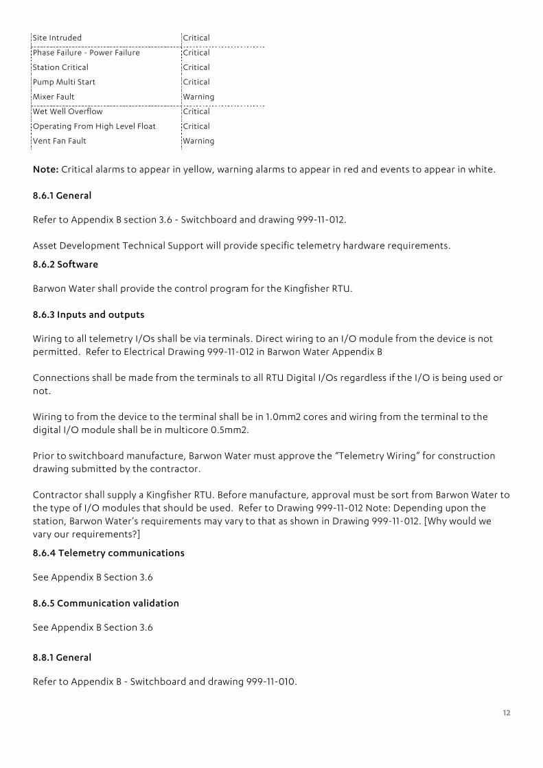
Site Intruded Critical
Phase Failure - Power Failure Critical
Station Critical Critical
Pump Multi Start Critical
Mixer Fault Warning
Wet Well Overflow Critical
Operating From High Level Float Critical
Vent Fan Fault Warning
Note: Critical alarms to appear in yellow, warning alarms to appear in red and events to appear in white.
8.6.1 General
Refer to Appendix B section 3.6 - Switchboard and drawing 999-11-012.
Asset Development Technical Support will provide specific telemetry hardware requirements.
8.6.2 Software
Barwon Water shall provide the control program for the Kingfisher RTU.
8.6.3 Inputs and outputs
Wiring to all telemetry I/Os shall be via terminals. Direct wiring to an I/O module from the device is not permitted. Refer to Electrical Drawing 999-11-012 in Barwon Water Appendix B
Connections shall be made from the terminals to all RTU Digital I/Os regardless if the I/O is being used or not.
Wiring to from the device to the terminal shall be in 1.0mm2 cores and wiring from the terminal to the digital I/O module shall be in multicore 0.5mm2.
Prior to switchboard manufacture, Barwon Water must approve the “Telemetry Wiring” for construction drawing submitted by the contractor.
Contractor shall supply a Kingfisher RTU. Before manufacture, approval must be sort from Barwon Water to the type of I/O modules that should be used. Refer to Drawing 999-11-012 Note: Depending upon the station, Barwon Water’s requirements may vary to that as shown in Drawing 999-11-012. [Why would we vary our requirements?]
8.6.4 Telemetry communications
See Appendix B Section 3.6
8.6.5 Communication validation
See Appendix B Section 3.6
8.8.1 General
Refer to Appendix B - Switchboard and drawing 999-11-010.

13
8.8.2 Flow measurement
A Siemens “Magflow”, ABB “Wastewater” or Combined Instruments magnetic flowmeter having a 4-20mA flow analogue output and a pulse output proportional to volume is required.
8.8.5 Level sensors
Level sensors shall be a hydrostatic probe. Make and Model as per “Barwon Water Electrical Requirements for External Design” document. The hydrostatic probe shall be mounted in a minimum 100mm diameter stilling tube with access to stilling tube to be from the top of the pump station. Lower end of the stilling tube shall terminate between the snore of pump and the cut-out level.
8.8.6 Float-switch
Following float switches shall be installed:
Wet Well High Level; High Level for Backup PLC; and, Overflow and Surcharge.
8.8.8.2 Moulded-case circuit-breakers
For drives above 11kW the three phase circuit breaker shall be the “Motor Protection Type”
8.8.8.5 Thermal-overload relays
The thermal overload relay shall have “Automatic” and “Manual” reset capabilities and be supplied with auxiliary NO and NC contacts.
8.10 Wire numbering convention
Refer to drawings 999-11-010, 999-11-011 and 999-11-012.
8.11.1 Digital inputs and outputs
The contractor shall adopt the wiring numbers as shown in drawing 999-11-012.
8.11.2 Analog inputs and outputs
The contractor shall adopt the wiring numbers as shown in drawing 999-11-012.
8.12.1 General
The contractor shall adopt the wiring numbers as shown in drawing 999-11-011.
8.12.2 Loop tag definition guidelines
The contractor shall adopt the wiring numbers as shown in drawing 999-11-012.
9. Wet-well pipework
9.1.2 Sizing
(c) The minimum diameter of a rising main shall be DN150 unless Barwon Water approves otherwise.

14
(d) All pipework within the wet-well and valve chamber shall be ductile iron and shall be coated with an approved corrosion resistant coating.
9.1.3 Type
Discharge pipework in the wet-well and valve chamber shall be DICL or steel.
9.2.3 Scour/Emergency by-pass connection
An emergency by pass pumping point within the valve chamber pit is required at every installation. The facility shall include a branch line from the pressure main incorporating a sluice valve, a non-return valve, a 90º bend and a flanged riser to within 100mm of the top of the valve chamber. The sluice valve must be able to be operated from the surface above the valve chamber. Note: not required for scours.
9.2.4 Sewage air-release valves
The minimum diameter shall be DN 80. Air valves must be of the type approved for use on sewer mains. Air valves shall be located in a concrete pit fitted with a lockable aluminium cover. Provision must be included in the design to allow air to escape from the pit. On long rising mains, Barwon Water may deem it necessary to provide odour control on all air valve discharges.
9.3.1 General
A separate valve chamber is required. The typical discharge valve arrangement show in Figure 3.3 is suitable.
The valve chamber shall have a duck-bill style valve, to facilitate when required the discharge of liquid from the valve chamber to the wet-well. The valve shall be accessible form the landing/ladder within the wet-well.
A 25mm diameter tapping point suitable for a pressure gauge is to be provided.
9.3.2 Design
Non-return valves shall be of the swing check type fitted with counter weights.
Isolation valves shall be sluice valves.
9.3.3 Dismantling joints
Dismantling joints are required.
9.4.1 Condition monitoring and maintenance
The designer must liaise with Barwon Water on the design and location of fittings required for condition monitoring and maintenance.
10. Pressure main
10.1.1 General
The designer shall include the results of the surge and fatigue analysis in the design report.

15
10.2.2 Road reserves
Pressure mains must be located in road reserves unless special approval is granted by Barwon Water to locate them elsewhere.
10.3 Hydraulic design
Sized to accommodate flows for the next 50 years.
10.4.3 Surge
The designer shall provide evidence that the rising main can withstand anticipated maximum surge pressure.
10.9.2 Isolating valves
Isolation valves shall be sluice valves. All sluice valves for sewage shall be anti-clockwise closing
Two-way air valves shall be provided on all high points on rising mains with crests.
10.9.3 Gas release valves
Located at on all high points on rising mains with crests as well as where necessary to control water hammer.
10.9.5 Scours
Scour points shall be provided on all low points on rising mains with crests. These shall be located within a concrete it fitted with a lockable aluminium cover and shall include a branch line from the pressure main incorporating a resilient seated sluice valve. Where possible the scour points shall drain to a separate sewer. Otherwise they shall include a 90º bend and a flanged riser to within 100mm of the top of the pit. The minimum diameter of scour lines shall be DN 100.
10.10 Odour and septicity control
The designer shall calculate detention times and design adequate odour and septicity controls. The designer is required to provide calculations of detention times including gas phase Hydrogen Sulphide and dissolved sulphide generation within the wet-well and pressure main discharge point. This design shall ensure that the sulphide generation potential in rising mains that discharge to standard manholes is kept to a level that is not likely to cause nuisance odour. These calculations shall be provided to Barwon Water.
10.11.1 General
Internal exposed surfaces of the receiving structure must be coated with an approved coating to prevent corrosion.
10.11.2 Discharge manholes
Exposed concrete surfaces in the receiving manhole shall be coated with an epoxy lining system Eg. Tufflon Polyurea P90 / Epigen Epoxy Resin 1311 or approved equivalent.

16
11. Structural design
11.2.5 Pumping station walls
Rectangular walls are not acceptable.
Barwon Water will not accept the design for a pump station with an integral valve chamber.
11.3.2 Products and materials
The minimum class of pipes and fittings for pressure mains shall be PN 12.
11.3.4.2 Pipe cover
The minimum cover to the top of the rising main shall be 1.0m in nature strips and footpaths and 1.2m in roadways.
12. Supporting systems
12.1.3 Telephone/Telemetry lines
A telephone connection will not be required. Communication to the site will be maintained via the telemetry system.
12.3 Security Barwon Water will nominate if security fencing is required. Security fencing shall not impede access to pump station equipment.
All switchboard doors shall have handles installed that allow the use of a padlock for locking purposes with exception of the Electricity Meter Door. Padlocks are to be purchased from Barwon Waters approved Locksmith according to the system below.
Lock required Location
2B1.1 Geelong SPS Switchboard and Entry Covers
2B1.2 Geelong SPS Fences and Gates
Note: The 2B1 lock sequence includes: Geelong – Lara – Leopold
2B2.1 Inland SPS Switchboard and Entry Covers
2B2.2 Inland SPS Fences and Gates
Note: The 2B2 lock sequence includes: Portarlington – Colac – Winchelsea – Bannockburn – Clifton Springs
2B3.1 Costal SPS Switchboard and Entry Covers
2B3.2 Costal SPS Fences and Gates
Note: The 2B3 lock sequence includes: Anglesea–Aireys Inlet–Apollo Bay–Barwon Heads–Ocean Grove–Queenscliff–Torquay–Lorne
All Electricity Meter Cubicles require PI-549B locks.
12.4 Fire control
Fire fighting facilities must be provided in accordance with the requirements of the building permit issued by the council.

17
13. Health and safety
13.1 General Barwon Water safety requirements are covered by a corporate safety system called SafeAs. This system details requirements for:
• Ventilation;
• Ladders and landings;
• Davit arm connection point;
• Lifting pumps;
• Location of switchboard in relation to the wet-well entry;
• Mesh in station openings;
• Door alarm; and
• Elimination of tripping hazards.
13.4 Confined spaces Signs identifying confined spaces must be provided. This sign must be located in a prominent position adjacent to the entry of the confined space.
Mixer warning signs must be provided.
In some instances, “No Parking” and/or “Barwon Water Vehicles Only” signs will also be required. Barwon Water will advise when these are necessary.
15. Design documentation and drawings Appendix A Typical pre-commissioning checklist
Appendix B Typical commissioning schedule
Appendix C AC voltage mitigation of steel pipelines
C1 introduction
C2 Inductive coupling hazard
C3 Conductive coupling hazard
C4 Capacitive coupling hazard
C5 Mitigation
Appendix D Pressure main calculator
D1 Pressure main calculator
D2 Nomenclature
D3 Principles and criteria
D3.1 Design flows
D3.2 Detention time
D3.3 Minimum internal diameter of pressure main
D3.4 Maximum internal diameter of pressure main
D3.5 Minimum pumping rate
D3.6 Maximum pumping rate
D3.7 Pump control volume (cut-in / cut-out volume) and pump starts

18
D4 Instructions
D4.1 Data entry
D4.2 Internal diameter of pressure main
D4.3 Pumping rate and detention time
D4.4 Wet-well control volume / actual starts / detention time
D4.5 Printing A
D4.6 New calculation
D4.7 Reset
Appendix E Detailed design checklist
Tables
Table 1.1 Typical asset design life
Table 3.1 Clearances between pressure mains and underground
Services
Table 5.1 Default control levels
Table 8.1 Default alarm levels
Table 8.2 Typical local and remote alarms
Table 8.3 Typical remote monitored conditions
Table 10.1 Pressure de-rating factors for plastic pipes at
Elevated temperatures
Table 10.2 Fatigue de-rating factors for thermoplastic pipes
Table 10.3 Scour sizes 1
Table 11.1 Requirement for bulkheads
Figures
Figure 1.1 Concept design flowchart
Figure 2.1 SPS Overflow risk reduction decision diagram
Figure 2.2 Typical pre-commissioning and commissiong process
Figure 2.3 Typical handover to water agency
Figure 3.1 Deflection at joints
Figure 3.2 Deflection using soc-soc bends
Figure 3.3 Deflection using soc-soc connectors
Figure 5.1 Typical emergency storage – Configuration 1
Figure 5.2 Typical emergency storage – Configuration 2
Figure 5.3 Typical emergency storage – Configuration 3
Figure 5.4 Typical emergency storage – Configuration 4
Figure 8.1 Alarm level control settings
Figure 10.1 Typical surge wave
Figure 10.2 Typical fatigue cycle

19
Appendix A
1. Valves
Sluice valves are to be:
• A minimum of class 12;
• Conforming to AS 2638.2 - 1999;
• Flanged;
• Resilient seated; and,
• Anti-clockwise closing.
Penstock valves are to be:
• To be defined;
Air release valves are to be:
• 316 stainless steel;
• two way;
• minimum diameter DN 80; and,
• suitable for use in sewer

20
Appendix B
Major Infrastructure
Electrical design brief
(Separate document)


