
Supplement to the WSAA dual water supply systems to the... · Supplement to the WSAA . Dual Water...
17
Supplement to the WSAA Dual Water Supply Systems First edition Melbourne retail water agencies edition Version 1.1 Melbourne retail water agencies edition of the Water Supply Code of Australia WSA 03-2002 For land development
Transcript of Supplement to the WSAA dual water supply systems to the... · Supplement to the WSAA . Dual Water...
Supplement to the WSAA Dual Water Supply Systems First edition Melbourne retail water agencies edition Version 1.1 Melbourne retail water agencies edition of the Water Supply Code of Australia WSA 03-2002 For land development
Table of contents
NDW 1 Introduction.....................................................................................................................................................................4 NDW 1.1 Scope ....................................................................................................................................................................... 4
NDW 1.2 Application .............................................................................................................................................................. 4
NDW 3 Design ............................................................................................................................................................................ 4
NDW 3.1.1 Distribution demand ......................................................................................................................................... 4
NDW 3.1.2 Reticulation demand ......................................................................................................................................... 5
NDW 3.4.2 Temporary cross connection ........................................................................................................................... 5
NDW 3.5 Sizing of mains ......................................................................................................................................................... 6
NDW 3.5.1 General ............................................................................................................................................................. 6
NDW 3.5.2 Fire flows .......................................................................................................................................................... 6
NDW 3.5.4 Head losses/Roughness coefficients ............................................................................................................... 6
NDW 3.6 Allowable service pressures .................................................................................................................................... 7
NDW 3.7 Location of mains .................................................................................................................................................... 7
NDW 3.8 Main depths ............................................................................................................................................................ 8
NDW 3.12 Hydrants (spring only) ........................................................................................................................................... 8
NDW 3.13 Cul-de-sacs and dead end non-drinking water mains ........................................................................................... 9
NDW 3.16 Thrust and anchor blocks ...................................................................................................................................... 9
Part 3 - Construction ................................................................................................................................................................. 10
NDW 7 Property connections ................................................................................................................................................... 10
NDW 7.1 Tapping of mains .................................................................................................................................................... 10
NDW 8 Acceptance testing of property services ...................................................................................................................... 10
NDW 8.2 Testing in conjunction with reticulation main ....................................................................................................... 10
Part 4 - Standard drawings ......................................................................................................................................................... 11
NDW 10 Listing of standard drawings ........................................................................................................................................ 11
NDW 11.2 WAT–1801-V – Typical mains construction – main arrangement for cul-de-sacs and court bowls ...................... 12
NDW 11.4 WAT–1803-V – Property services – typical service layouts and alternative marking systems .............................. 12
NDW 11.5 WAT–1804-V – Property services – typical service arrangement ......................................................................... 12
NDW 11.6 WAT–1805-V – Property services – standard tapping methods ........................................................................... 12
NDW 11.7 WAT–1806-V – Property services – single and split services across carriageways ................................................ 12
NDW 11.8 WAT–1807-V – Property services – typical above-ground meter arrangement ................................................... 13
NDW 11.10 WAT–1810-V– Embedment and trench fill – main arrangement for dual water supply systems ......................... 13
NDW 11.14 WAT–1822 – Typical appurtenance installation – hydrant, valve and flushing installation on PE mains using compression fittings ............................................................................................................................................................. 13
Supporting documentation and dual water supply system
Introduction
Barwon Water’s design and constructions requirements for dual water mains for land development works is the Water Services Association of Australia Dual Water Supply Systems First Edition of the Melbourne Retail Water Agencies Edition Version 1.1. This document is a supplement to the Melbourne Retail Water Agencies Edition of the Water Supply Code of Australia WSA 03-2002 with the exceptions listed in this supplement. General
This supplement should be read in conjunction with the following documents:
• WSAA Dual Water Supply Systems First Edition, Melbourne Retail Water Agencies Edition Version 1.1, Melbourne Retail Water Agencies Edition of the Water Supply Code of Australia WSA 03-2002, (the “MRWA Supplement”)
• Barwon Water’s Supplement to WSAA Water Reticulation Code of Australia Melbourne Retail Water Agencies Edition – Version 1 - WSA-03-2003-2.3; and
• WSAA Water Reticulation Code of Australia Melbourne Retail Water Agencies Edition – Version 1 - WSA-03-2003-2.3.
Operation
The user can refer to the index of the supplementary documentation to establish further Barwon Water requirements to be met. The clause numbering of this supplementary document matches the WSAA Code. Innovative solutions
WSAA Dual Water Supply System First Edition Melbourne Retail Water Agencies Edition 1.1 and this supporting documentation essentially provide ‘deemed-to-comply’ solutions for the creation of water agency dual water assets. Alternative solutions, practices, equipment and methodologies will continue to evolve and offer opportunities to improve the creation of these assets. Barwon Water encourages employment of any innovation that offers enhanced productivity and serviceability, but Barwon Water input should be sought before any innovative system is installed. Responsibilities
Designers and constructors are responsible for their respective aspects of the design and construction process. It is the designer/constructor’s responsibility to justify any variation from the requirements set out in the WSAA Dual Water Supply System First Edition Melbourne Retail Water Agencies Edition 1.1 (including the attached Barwon Water conditions) and/or the Barwon Water Construction Drawings plus any specific directions given by Barwon Water for the particular project. The designer/constructor is to obtain Barwon Water endorsement for any variation.
4
Amendment history
Update number Brief description Effective date
0.1 Interim edition only
30 September 2010
NDW 1 Introduction
NDW 1.1 Scope
This supplement covers the design and construction of dual water supply systems in the Barwon Water region. Due to the high capital cost of treatment plants and distribution pipe work, Barwon Water will only supply recycled water to nominated recycled water supply areas. Developers and consultants must confirm with Barwon Water that a non-drinking water supply can be provided by the corporation before designing a dual water supply system or marketing developments with dual water supply. This supplement addresses the provision of a non-drinking water supply and its impacts on (drinking) water supply design and construction. NDW 1.2 Application
This supplement should be read in conjunction with the following documents:
• Barwon Water’s supplement to WSAA Water Reticulation Code of Australia Melbourne Retail Water Agencies Edition –Version1 - WSA-03-2003-2.3; and
• WSAA Dual Water Supply Systems First Edition Melbourne Retail Water Agencies Edition Version 1.1. Melbourne Retail Water Agencies Edition of the Water Supply Code of Australia WSA 03-2002.
Where there is a discrepancy between any of these documents, this document and Barwon Water’s Supplement to the WSAA Water Reticulation Code of Australia Melbourne Retail Water Agencies Edition –Version1 - WSA-03-2003- 2.3 will take precedence, in that order.
NDW 3 Design
NDW 3.1.1 Distribution demand
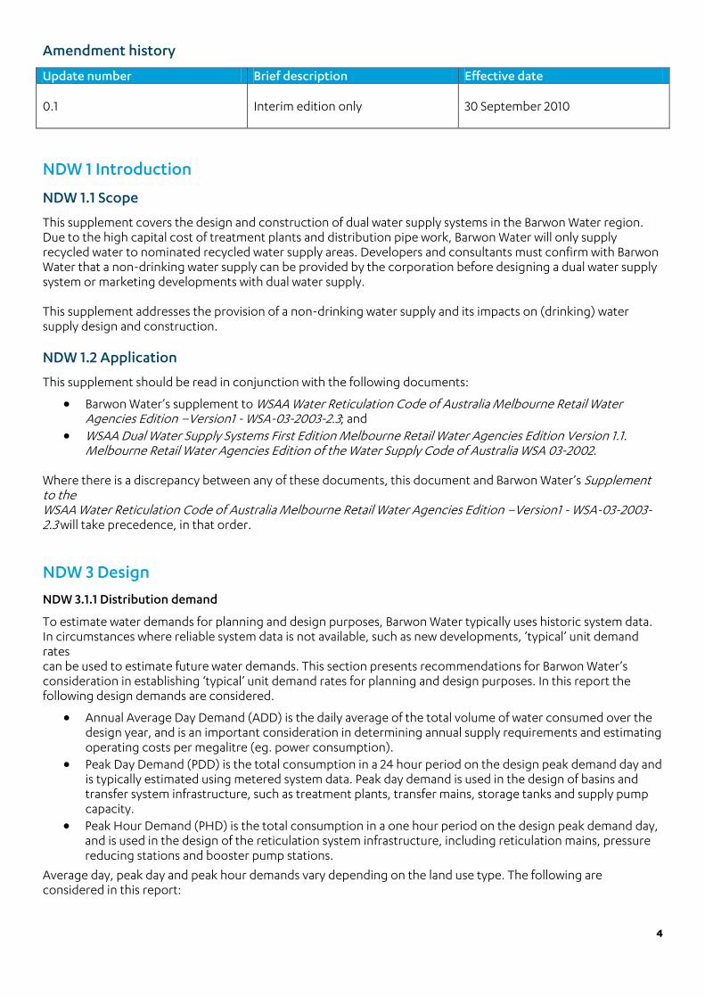
To estimate water demands for planning and design purposes, Barwon Water typically uses historic system data. In circumstances where reliable system data is not available, such as new developments, ’typical’ unit demand rates can be used to estimate future water demands. This section presents recommendations for Barwon Water’s consideration in establishing ‘typical’ unit demand rates for planning and design purposes. In this report the following design demands are considered.
• Annual Average Day Demand (ADD) is the daily average of the total volume of water consumed over the design year, and is an important consideration in determining annual supply requirements and estimating operating costs per megalitre (eg. power consumption).
• Peak Day Demand (PDD) is the total consumption in a 24 hour period on the design peak demand day and is typically estimated using metered system data. Peak day demand is used in the design of basins and transfer system infrastructure, such as treatment plants, transfer mains, storage tanks and supply pump capacity.
• Peak Hour Demand (PHD) is the total consumption in a one hour period on the design peak demand day, and is used in the design of the reticulation system infrastructure, including reticulation mains, pressure reducing stations and booster pump stations.
Average day, peak day and peak hour demands vary depending on the land use type. The following are considered in this report:
5
• Single dwelling residential (500 m2 lots) - areas comprised of standalone residential buildings with an average lot size of 500 m2.
• Single dwelling residential (1,000 m2 lots) - areas comprised of standalone residential buildings with an average lot size of 1,000 m2.
• Multi-unit residential (350 m2 lots and smaller) – areas with a residential build-out of up to 30 units per hectare.
• Commercial / light industrial - areas characterised by general neighbourhood businesses, industries and shopping centres.
• Community facilities- This category includes all land uses for schools, libraries, information centres and other similar community facilities.
• Active parkland - applicable to recreational facilities with large open spaces that are actively irrigated, such as playing fields or local parks. The primary end use for this land use is irrigation with some additional demands expected for public facilities such as toilet flushing, hand washing and personal consumption.
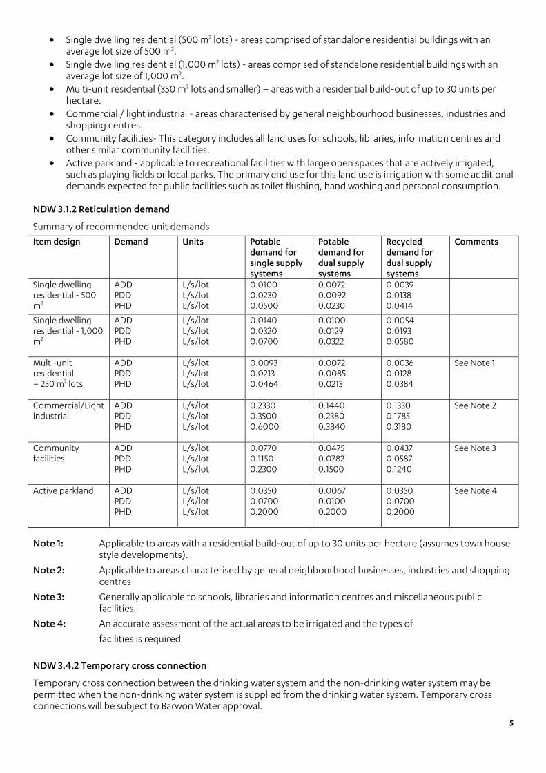
NDW 3.1.2 Reticulation demand
Summary of recommended unit demands
Item design Demand Units Potable demand for single supply systems
Potable demand for dual supply systems
Recycled demand for dual supply systems
Comments
Single dwelling residential - 500 m2
ADD PDD PHD
L/s/lot L/s/lot L/s/lot
0.0100 0.0230 0.0500
0.0072 0.0092 0.0230
0.0039 0.0138 0.0414
Single dwelling residential - 1,000 m2
ADD PDD PHD
L/s/lot L/s/lot L/s/lot
0.0140 0.0320 0.0700
0.0100 0.0129 0.0322
0.0054 0.0193 0.0580
Multi-unit residential – 250 m2 lots
ADD PDD PHD
L/s/lot L/s/lot L/s/lot
0.0093 0.0213 0.0464
0.0072 0.0085 0.0213
0.0036 0.0128 0.0384
See Note 1
Commercial/Light industrial
ADD PDD PHD
L/s/lot L/s/lot L/s/lot
0.2330 0.3500 0.6000
0.1440 0.2380 0.3840
0.1330 0.1785 0.3180
See Note 2
Community facilities
ADD PDD PHD
L/s/lot L/s/lot L/s/lot
0.0770 0.1150 0.2300
0.0475 0.0782 0.1500
0.0437 0.0587 0.1240
See Note 3
Active parkland
ADD PDD PHD
L/s/lot L/s/lot L/s/lot
0.0350 0.0700 0.2000
0.0067 0.0100 0.2000
0.0350 0.0700 0.2000
See Note 4
Note 1: Applicable to areas with a residential build-out of up to 30 units per hectare (assumes town house style developments).
Note 2: Applicable to areas characterised by general neighbourhood businesses, industries and shopping centres
Note 3: Generally applicable to schools, libraries and information centres and miscellaneous public facilities.
Note 4: An accurate assessment of the actual areas to be irrigated and the types of
facilities is required
NDW 3.4.2 Temporary cross connection
Temporary cross connection between the drinking water system and the non-drinking water system may be permitted when the non-drinking water system is supplied from the drinking water system. Temporary cross connections will be subject to Barwon Water approval.

6
Temporary cross connections must be provided at specified locations, and in accordance with Barwon Waters Standard Drawing – Drinking and Recycled Water Cross Connection Detail 70202 and 70203. NDW 3.5 Sizing of mains
NDW 3.5.1 General
Unless stated otherwise in Barwon Water’s offer for the provision of services to the subdivision, sizing of water mains for non-drinking water pipelines must be the same as the drinking water pipeline sizes. Also, unless stated otherwise in Barwon Water’s offer for the provision of services to the subdivision, sizing of water mains for drinking water pipelines must be determined in accordance with Section 3.2.3 of Barwon Water’s Supplement to the WSAA Water Reticulation Code of Australia Melbourne Retail Water Agencies Edition – Version1 - WSA-03-2003-2.3 and that code; that is, assuming there is no saving in pipeline sizing possible from dual supply. Irrespective of the sizes determined above, the following limitations apply:
a) The minimum pipe size needs to be DN 63 Polyethylene (PE) pipe or equivalent in court bowls and DN 100 elsewhere (Refer to Appendix NDW A); and b) For non-drinking water with turbidity ≥2 NTU, the minimum velocity should be at least 0.8 m/s at least once per day when modelled on the peak day demand for the ultimate development (refer to Clause 2.2.3 of WSA 03). Barwon Water designates mains DN300 and above as feeder mains. These are non-tapping mains and a smaller reticulation main is required to be installed in parallel with the feeder main to provide water tappings to lots. NDW 3.5.2 Fire flows
Barwon Water does not specifically size water mains for fire fighting flows. NDW 3.5.4 Head losses/roughness coefficients
Barwon Water’s pipeline design criteria for dual water supply systems are listed in table 3.5. Table 3.5 Design criteria
Pipeline purpose Potable Recycled Comments Transfer mains to storages
Size to maintain capacity above the reserve storage level
Size to maintain capacity above the reserve storage level
See note 1
Feeder and reticulation mains
Size for minimum service pressure criteria
Size for minimum service pressure criteria
See note 1
Design criterion Units Potable Recycled Comments
Target head losses m/km
5 m/km for ≤DN 150 3m/km for ≥DN200
5 m/km for ≤DN 150 3m/km for ≥DN200
See note 2
Target velocities m/s 0.8 to 1.4
0.8 to 1.4
Maximum velocity m/s 2.0
2.0
Note 1: Design based on Hazen-Williams Equation with a friction factor of 130 Note 2: Higher head losses may be acceptable as long as target pressures within the system are maintained with approval from Barwon Water.
7
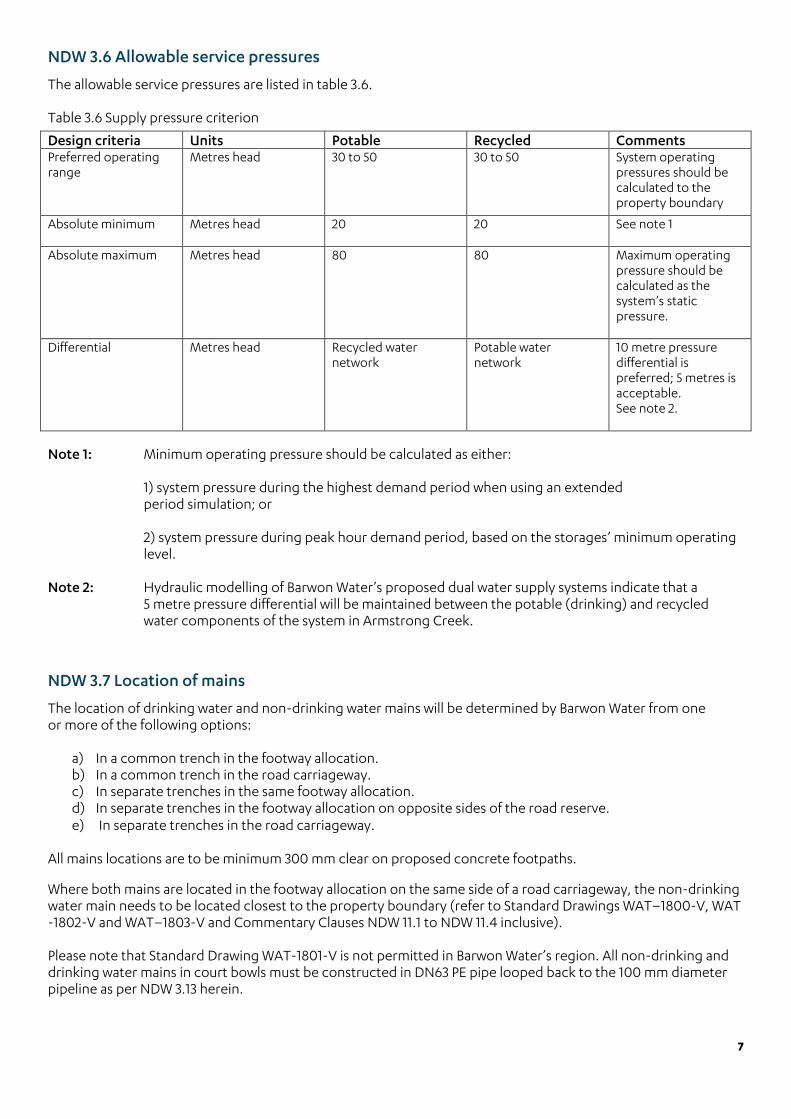
NDW 3.6 Allowable service pressures
The allowable service pressures are listed in table 3.6. Table 3.6 Supply pressure criterion
Design criteria Units Potable Recycled Comments Preferred operating range
Metres head
30 to 50 30 to 50
System operating pressures should be calculated to the property boundary
Absolute minimum
Metres head
20 20 See note 1
Absolute maximum
Metres head
80 80
Maximum operating pressure should be calculated as the system’s static pressure.
Differential
Metres head
Recycled water network
Potable water network
10 metre pressure differential is preferred; 5 metres is acceptable. See note 2.
Note 1: Minimum operating pressure should be calculated as either: 1) system pressure during the highest demand period when using an extended period simulation; or 2) system pressure during peak hour demand period, based on the storages’ minimum operating level. Note 2: Hydraulic modelling of Barwon Water’s proposed dual water supply systems indicate that a
5 metre pressure differential will be maintained between the potable (drinking) and recycled water components of the system in Armstrong Creek.
NDW 3.7 Location of mains
The location of drinking water and non-drinking water mains will be determined by Barwon Water from one or more of the following options:
a) In a common trench in the footway allocation. b) In a common trench in the road carriageway. c) In separate trenches in the same footway allocation. d) In separate trenches in the footway allocation on opposite sides of the road reserve. e) In separate trenches in the road carriageway.
All mains locations are to be minimum 300 mm clear on proposed concrete footpaths. Where both mains are located in the footway allocation on the same side of a road carriageway, the non-drinking water main needs to be located closest to the property boundary (refer to Standard Drawings WAT–1800-V, WAT -1802-V and WAT–1803-V and Commentary Clauses NDW 11.1 to NDW 11.4 inclusive). Please note that Standard Drawing WAT-1801-V is not permitted in Barwon Water’s region. All non-drinking and drinking water mains in court bowls must be constructed in DN63 PE pipe looped back to the 100 mm diameter pipeline as per NDW 3.13 herein.
8
Where the available space in the footway allocation is insufficient to accommodate both mains, each main will need to be located separately - on either side of the road carriageway, in the respective footway allocations (Refer to Standard Drawing WAT–1102). Where no footway allocation agreement exists, such as for footways less than 3 metres wide, the drinking water main (or non-drinking water main if nominated by Barwon Water will need be laid as close as possible to the kerb to allow room for other services, while also allowing sufficient clearance for maintenance excavation. The minimum clearance from the back of the kerb is 300 mm. Where both mains are located under the road carriageway, the non-drinking water main should be located nearer to the centre line. NDW 3.8 Main depths
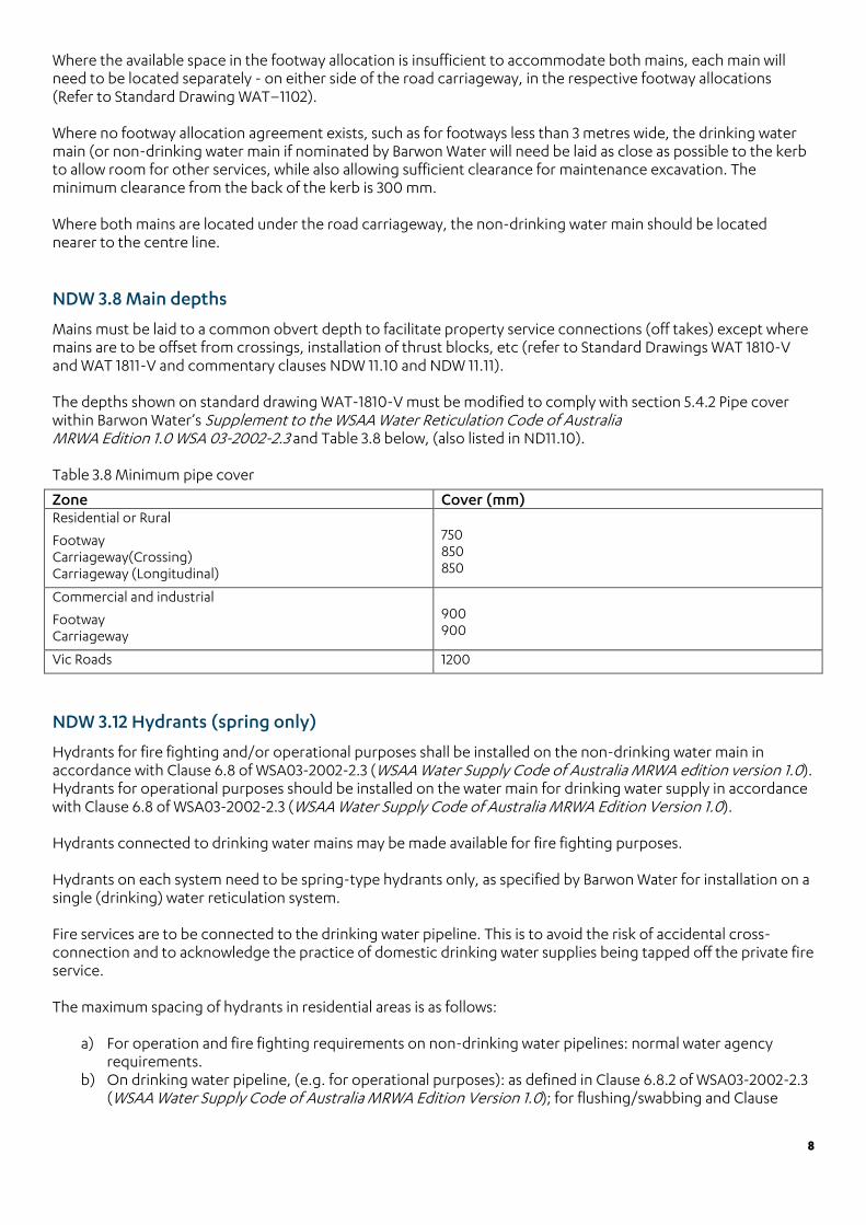
Mains must be laid to a common obvert depth to facilitate property service connections (off takes) except where mains are to be offset from crossings, installation of thrust blocks, etc (refer to Standard Drawings WAT 1810-V and WAT 1811-V and commentary clauses NDW 11.10 and NDW 11.11). The depths shown on standard drawing WAT-1810-V must be modified to comply with section 5.4.2 Pipe cover within Barwon Water’s Supplement to the WSAA Water Reticulation Code of Australia MRWA Edition 1.0 WSA 03-2002-2.3 and Table 3.8 below, (also listed in ND11.10). Table 3.8 Minimum pipe cover
Zone Cover (mm) Residential or Rural
Footway Carriageway(Crossing) Carriageway (Longitudinal)
750 850 850
Commercial and industrial
Footway Carriageway
900 900
Vic Roads 1200
NDW 3.12 Hydrants (spring only)
Hydrants for fire fighting and/or operational purposes shall be installed on the non-drinking water main in accordance with Clause 6.8 of WSA03-2002-2.3 (WSAA Water Supply Code of Australia MRWA edition version 1.0). Hydrants for operational purposes should be installed on the water main for drinking water supply in accordance with Clause 6.8 of WSA03-2002-2.3 (WSAA Water Supply Code of Australia MRWA Edition Version 1.0). Hydrants connected to drinking water mains may be made available for fire fighting purposes. Hydrants on each system need to be spring-type hydrants only, as specified by Barwon Water for installation on a single (drinking) water reticulation system. Fire services are to be connected to the drinking water pipeline. This is to avoid the risk of accidental cross-connection and to acknowledge the practice of domestic drinking water supplies being tapped off the private fire service. The maximum spacing of hydrants in residential areas is as follows:
a) For operation and fire fighting requirements on non-drinking water pipelines: normal water agency requirements.
b) On drinking water pipeline, (e.g. for operational purposes): as defined in Clause 6.8.2 of WSA03-2002-2.3 (WSAA Water Supply Code of Australia MRWA Edition Version 1.0); for flushing/swabbing and Clause
9
6.8.9 of WSA03-2002-2.3 (WSAA Water Supply Code of Australia MRWA Edition Version 1.0);for high and low points.
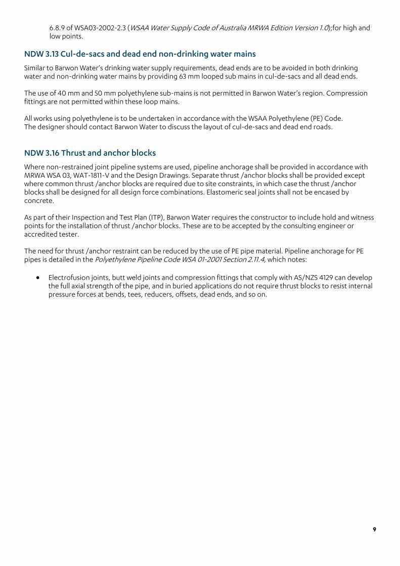
NDW 3.13 Cul-de-sacs and dead end non-drinking water mains
Similar to Barwon Water’s drinking water supply requirements, dead ends are to be avoided in both drinking water and non-drinking water mains by providing 63 mm looped sub mains in cul-de-sacs and all dead ends. The use of 40 mm and 50 mm polyethylene sub-mains is not permitted in Barwon Water’s region. Compression fittings are not permitted within these loop mains. All works using polyethylene is to be undertaken in accordance with the WSAA Polyethylene (PE) Code. The designer should contact Barwon Water to discuss the layout of cul-de-sacs and dead end roads. NDW 3.16 Thrust and anchor blocks
Where non-restrained joint pipeline systems are used, pipeline anchorage shall be provided in accordance with MRWA WSA 03, WAT-1811-V and the Design Drawings. Separate thrust /anchor blocks shall be provided except where common thrust /anchor blocks are required due to site constraints, in which case the thrust /anchor blocks shall be designed for all design force combinations. Elastomeric seal joints shall not be encased by concrete. As part of their Inspection and Test Plan (ITP), Barwon Water requires the constructor to include hold and witness points for the installation of thrust /anchor blocks. These are to be accepted by the consulting engineer or accredited tester. The need for thrust /anchor restraint can be reduced by the use of PE pipe material. Pipeline anchorage for PE pipes is detailed in the Polyethylene Pipeline Code WSA 01-2001 Section 2.11.4, which notes:
• Electrofusion joints, butt weld joints and compression fittings that comply with AS/NZS 4129 can develop the full axial strength of the pipe, and in buried applications do not require thrust blocks to resist internal pressure forces at bends, tees, reducers, offsets, dead ends, and so on.

10
Part 3 - Construction
NDW 7 Property connections
NDW 7.1 Tapping of mains
Tapping of the drinking water and non-drinking water reticulation mains shall be made at the time of construction with the main dry and completed before completing embedment and placement of trench fill. Tapping shall be as detailed in Barwon Water’s Standard Drawings:
• Typical cross section – Recycled water tapping 70200 • Typical plan section - Recycled water tapping 70201
For PVC, GRP and DI mains, an approved tapping band/saddle/tee shall be used with TPFNR Ferrule Cock. For PE mains, an approved electro fusion tapping/saddle/tee shall be used.
NDW 8 Acceptance testing of property services
NDW 8.2 Testing in conjunction with reticulation main
During pressure testing of the reticulation main, the TPFNR Ferrule Cock or electro fusion tapping saddle (with integral cutter and service isolation valve) must be open for each service connection, . For each property service, the ball valve at the property shall be closed. The appropriate ball valves at each property need to be temporarily opened to allow water to flow through the service. This will ensure any trapped air can escape, and to check that service connections are to the correct water supply main (drinking or non-drinking). The constructor is required to submit an ITP for Barwon Water approval prior to works beginning. The ITP will establish hold and witness points during the installation and commissioning of non-drinking water mains, including non-drinking water main-to-meter services. The ITP needs to specifically address commissioning procedures to identify any possible cross-contamination. Refer to EPA Victoria Draft Guidelines for Dual Pipe Water Recycling Schemes – Health and Environmental Risk Management. A commissioning process for the drinking and non-drinking water services is provided in Appendix B of the MRWA Supplement. This system integrity inspection should be conducted as part of the commissioning of the dual water supply system by Barwon Water’s quality auditors, the consultant and the contractor. The system integrity inspection is designed to eliminate the potential for cross contamination caused when a drinking water service is connected to a non-drinking water main. The consultant and the contractor must coordinate the timing of the Appendix B commissioning process in the MRWA Supplement with Barwon Water, and only proceed with the commissioning process with a Barwon Water Quality Auditor present. Failure to do so will result in the works being rejected and the testing will need to be repeated. If a Barwon Water Auditor is not available at the time the contractor wishes to conduct the commissioning, this will not be accepted as a reason for not having the commissioning witnessed. Barwon Water will bear no cost for the commissioning and/or repeating of the commissioning testing, to comply with this requirement.
11
Part 4 - Standard drawings
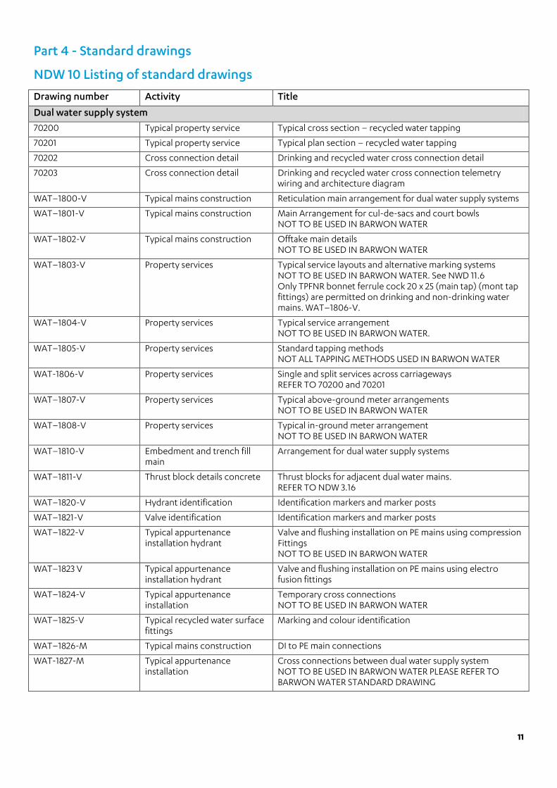
NDW 10 Listing of standard drawings
Drawing number Activity Title
Dual water supply system
70200 Typical property service Typical cross section – recycled water tapping
70201 Typical property service Typical plan section – recycled water tapping
70202 Cross connection detail Drinking and recycled water cross connection detail
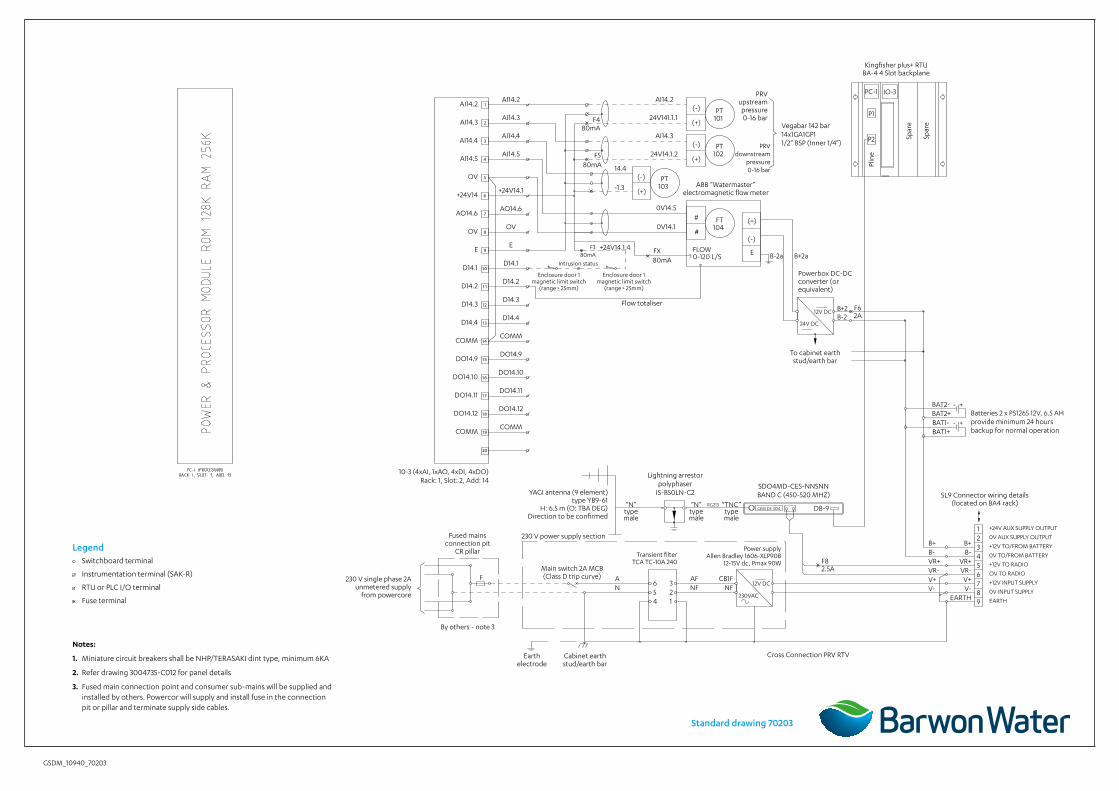
70203 Cross connection detail
Drinking and recycled water cross connection telemetry wiring and architecture diagram
WAT–1800-V Typical mains construction Reticulation main arrangement for dual water supply systems
WAT–1801-V Typical mains construction Main Arrangement for cul-de-sacs and court bowls NOT TO BE USED IN BARWON WATER
WAT–1802-V Typical mains construction Offtake main details NOT TO BE USED IN BARWON WATER
WAT–1803-V Property services Typical service layouts and alternative marking systems NOT TO BE USED IN BARWON WATER. See NWD 11.6 Only TPFNR bonnet ferrule cock 20 x 25 (main tap) (mont tap fittings) are permitted on drinking and non-drinking water mains. WAT–1806-V.
WAT–1804-V Property services Typical service arrangement NOT TO BE USED IN BARWON WATER.
WAT–1805-V
Property services
Standard tapping methods NOT ALL TAPPING METHODS USED IN BARWON WATER
WAT-1806-V Property services
Single and split services across carriageways REFER TO 70200 and 70201
WAT–1807-V
Property services
Typical above-ground meter arrangements NOT TO BE USED IN BARWON WATER
WAT–1808-V Property services
Typical in-ground meter arrangement NOT TO BE USED IN BARWON WATER
WAT–1810-V Embedment and trench fill main
Arrangement for dual water supply systems
WAT–1811-V
Thrust block details concrete Thrust blocks for adjacent dual water mains. REFER TO NDW 3.16
WAT–1820-V Hydrant identification Identification markers and marker posts
WAT–1821-V Valve identification Identification markers and marker posts
WAT–1822-V
Typical appurtenance installation hydrant
Valve and flushing installation on PE mains using compression Fittings NOT TO BE USED IN BARWON WATER
WAT–1823 V Typical appurtenance installation hydrant
Valve and flushing installation on PE mains using electro fusion fittings
WAT–1824-V Typical appurtenance installation
Temporary cross connections NOT TO BE USED IN BARWON WATER
WAT–1825-V Typical recycled water surface fittings
Marking and colour identification
WAT–1826-M Typical mains construction DI to PE main connections
WAT-1827-M Typical appurtenance installation
Cross connections between dual water supply system NOT TO BE USED IN BARWON WATER PLEASE REFER TO BARWON WATER STANDARD DRAWING

12
NDW 11.2 WAT–1801-V – Typical mains construction – main arrangement for cul de-sacs and court bowls Drawing WAT-1801-V is not permitted in Barwon Water’s region. Refer to NDW3.13 Cul-de-sacs and dead end nondrinking water mains herein.
NDW 11.4 WAT–1803-V – Property services – typical service layouts and alternative marking systems
Drawing WAT-1803-V is not permitted in Barwon Water’s region. Please refer to Barwon Water standard drawing 70201 – Typical plan section recycled water tapping. NDW 11.5 WAT–1804-V – Property services – typical service arrangement
Barwon Water or an approved contractor will undertake dual meter assemblies at time of connection. Please contact Barwon Water’s Development and Conservation department to discuss applications to connect. NDW 11.6 WAT–1805-V – Property services – standard tapping methods
This drawing has been generally varied for MRWA requirements. WAT–1805–V shows typical details for connecting a property service to a (reticulation) main and is similar in detail to WAT–1808–V. The method of connection is dependent on the pipeline material. Direct tapping of water mains (i.e. without use of a tapping band/saddle/tee) is not permitted. The tappings may be performed at surface level before the section of pipe is lowered into the trench. Pre-tapped connectors are not permitted in Barwon Water’s region. The preferred option for all connections installed during construction of the reticulation main is the use of TPFNR ferrule cock and tapping bands. Tapping bands used on PVC pipe should be full circle clamping to prevent over tightening and subsequent compression of the pipe. Stainless steel tapping band clamps should not be used on PVC-M and PVC-O pipes if tapping is conducted under pressure, since there is a risk that once depressurised the clamp type tapping bands will not reseal to provide a watertight connection. Electro fusion welded tapping saddles should be used at all times with new installations of PE pipe. Tapping of curved PE pipe should take place only at the top of the pipe to minimise stress around the tapping hole. Where dry tapping is performed, a plug cutter should be used, and all swarf removed. Under pressure tapping should be used only with systems that utilise plug cutters that retain the PE pipe wall plug within the cutter. Where welded tapping systems are used, the assembly should be allowed to fully cool naturally before cutting the mainline PE plug. Ball valves at the water main are not permitted. Type and application for alternative tapping products are provided, together with their relevant purchase specifications, which can be downloaded from the website. Product information WSA 03−2002 Supplement 1.1 MRWA Edition - Version 1.1 Copyright 47 available on the WSAA website is intended to be a guide, only products specifically approved by the Water Agency shall be used. Note: The Water Agency’s requirements for “dry” or “under pressure” tapping should be outlined in the Specification. NDW 11.7 WAT–1806-V – Property services – single and split services across carriageways
Drawing WAT-1803-V is not permitted in Barwon Water’s region. Please refer to Barwon Water standard drawing 70201 – Typical plan section recycled water tapping.
13
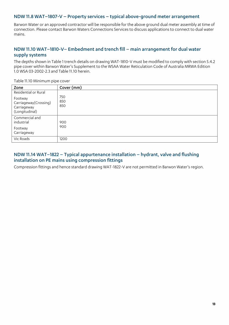
NDW 11.8 WAT–1807-V – Property services – typical above-ground meter arrangement
Barwon Water or an approved contractor will be responsible for the above ground dual meter assembly at time of connection. Please contact Barwon Waters Connections Services to discuss applications to connect to dual water mains. NDW 11.10 WAT–1810-V– Embedment and trench fill – main arrangement for dual water supply systems The depths shown in Table 1 trench details on drawing WAT-1810-V must be modified to comply with section 5.4.2 pipe cover within Barwon Water’s Supplement to the WSAA Water Reticulation Code of Australia MRWA Edition 1.0 WSA 03-2002-2.3 and Table 11.10 herein. Table 11.10 Minimum pipe cover
Zone Cover (mm) Residential or Rural
Footway Carriageway(Crossing) Carriageway (Longitudinal)
750 850 850
Commercial and industrial
Footway Carriageway
900 900
Vic Roads 1200
NDW 11.14 WAT–1822 – Typical appurtenance installation – hydrant, valve and flushing installation on PE mains using compression fittings Compression fittings and hence standard drawing WAT-1822-V are not permitted in Barwon Water’s region.
GSDM_10835_70200
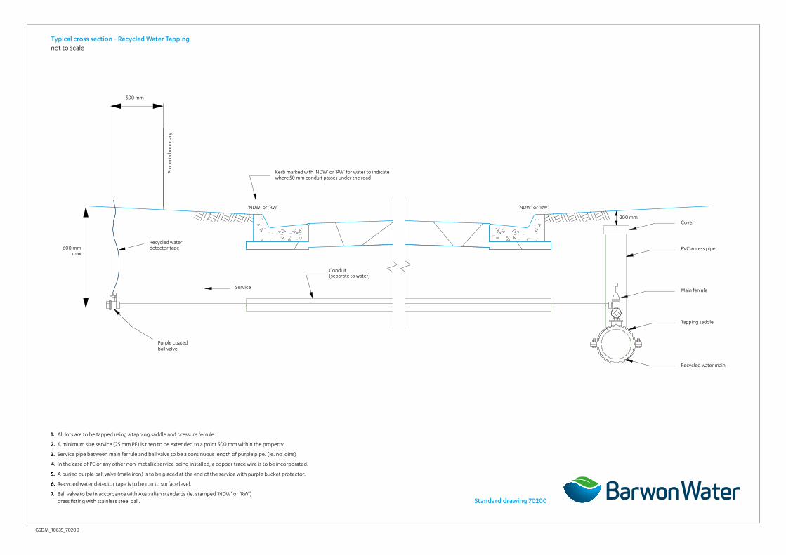
Typical cross section - Recycled Water Tappingnot to scale
Standard drawing 70200
500 mm
600 mm max
200 mm
Recycled water detector tape
Purple coatedball valve
Service
Conduit(separate to water)
Main ferrule
Tapping saddle
Recycled water main
PVC access pipe
Cover
Kerb marked with ‘NDW’ or ‘RW’ for water to indicate where 50 mm conduit passes under the road
‘NDW’ or ‘RW’ ‘NDW’ or ‘RW’
1. All lots are to be tapped using a tapping saddle and pressure ferrule.
2. A minimum size service (25 mm PE) is then to be extended to a point 500 mm within the property.
3. Service pipe between main ferrule and ball valve to be a continuous length of purple pipe. (ie. no joins)
4. In the case of PE or any other non-metallic service being installed, a copper trace wire is to be incorporated.
5. A buried purple ball valve (male iron) is to be placed at the end of the service with purple bucket protector.
6. Recycled water detector tape is to be run to surface level.
7. Ball valve to be in accordance with Australian standards (ie. stamped ‘NDW’ or ‘RW’) brass fitting with stainless steel ball.
Pro
pert
y bo
unda
ry
GSDM_10940_70201
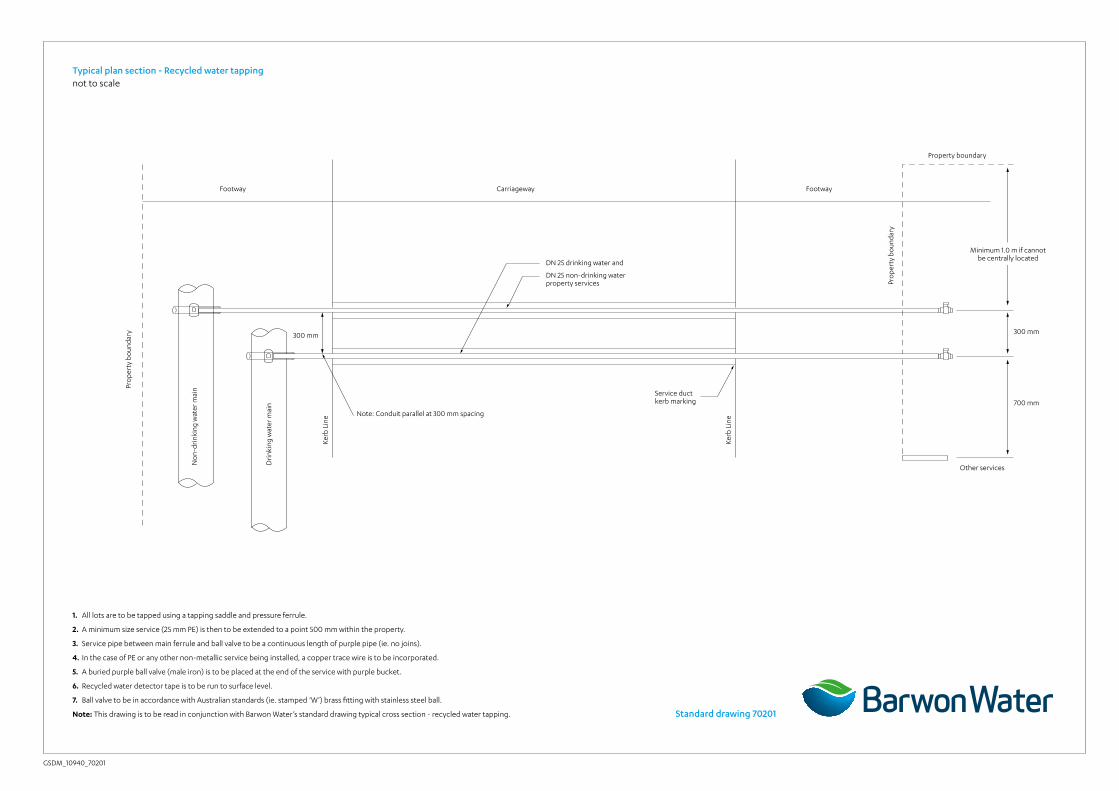
Typical plan section - Recycled water tappingnot to scale
1. All lots are to be tapped using a tapping saddle and pressure ferrule.
2. A minimum size service (25 mm PE) is then to be extended to a point 500 mm within the property.
3. Service pipe between main ferrule and ball valve to be a continuous length of purple pipe (ie. no joins).
4. In the case of PE or any other non-metallic service being installed, a copper trace wire is to be incorporated.
5. A buried purple ball valve (male iron) is to be placed at the end of the service with purple bucket.
6. Recycled water detector tape is to be run to surface level.
7. Ball valve to be in accordance with Australian standards (ie. stamped ‘W’) brass fitting with stainless steel ball.
Note: This drawing is to be read in conjunction with Barwon Water’s standard drawing typical cross section - recycled water tapping.
Pro
pert
y bo
unda
ry
No
n-dr
inki
ng w
ater
mai
n
Dri
nkin
g w
ater
mai
n
Note: Conduit parallel at 300 mm spacing
300 mm
Kerb
Lin
e
Kerb
Lin
e
Footway Footway
Other services
Carriageway
300 mm
700 mm
DN 25 drinking water and
DN 25 non-drinking water property services
Service ductkerb marking
Pro
pert
y bo
unda
ry
Property boundary
Minimum 1.0 m if cannot be centrally located
Standard drawing 70201

GSDM_11060_70202
Notes
1. All dimensions are in metres unless otherwise noted.
2. Unless specifically noted otherwise, all installation details are to WSAA and authority requirements.
3. All NDW mains and fittings shall be coloured lilac or alternatively sleeved with lilac coloured polyethylene. Colour shall be shade P23 as defined in AS2700.
4. DW and NDW mains shall be laid in a common trench. The DW main shall be laid closest to the property line.
5. NDW water mains shall be installed below DW mains at crossings.
Enclosure details:
DN80 powder coated (black or dark green), galvanised post. DN32 rails (top and bottom) to be connected to fence posts. Fencing to include bracing and strainer wires. Double gates to be 1200 mm width (each).
45mm diamond mesh 3.15 mm wire infill for wall and roof of enclosure. Wire mesh to be black or dark green, PVC coated.
Hinged double gates to be installed along front face of enclosure. Including provisions for lock installation. Lock to be provided by Barwon Water.
Thrust restraint schedule
Location Type Area (m2) Number
A 225Ø X 90° bend Concrete 2.38 3
Section A-Anot to scale
Plan not to scale
Potable and non-potable water cross connection
Note: All mains to be 150 mm diameter DICL class K9 unless otherwise noted.
Pressure reduction of 8 m head to be provided by pressure reducing valve: Max. HGL for drinking water: 133.2 m AHD
Max. HGL for non drinking water 125.2 m AHD Standard drawing 70202
GSDM_10940_70203
Notes:
1. Miniature circuit breakers shall be NHP/TERASAKI dint type, minimum 6KA
2. Refer drawing 3004735-C012 for panel details
3. Fused main connection point and consumer sub-mains will be supplied and installed by others. Powercor will supply and install fuse in the connection pit or pillar and terminate supply side cables.
Legend Switchboard terminal
Instrumentation terminal (SAK-R)
RTU or PLC I/O terminal
Fuse terminal
IO-3
P2
P1
PC-1
Spar
e
Spar
e
1AI14.2
2AI14.3
3AI14.4
4AI14.5
5OV
6+24V14
7AO14.6
8OV
9E
10D14.1
11D14.2
12D14.3
13D14.4
14COMM
15DO14.9
16DO14.10
(-)
(+)
(-)
(+)
#
#(-)
(+)
E
123456789
+24V AUX SUPPLY OUTPUT
0V AUX SUPPLY OUTPUT
0V TO/FROM BATTERY
+12V TO RADIO
OV TO RADIO
+12V INPUT SUPPLY
0V INPUT SUPPLY
EARTH
+12V TO/FROM BATTERYB+B-
VR+VR-V+V-
EARTH
B+B-VR+VR-V+V-
12V DC
230VAC
12V DC
24V DC
FLOW0-120 L/S
GEM DS SD4 DB-9RG213
- +BAT2-BAT2+
- +BAT1-BAT1+
F AN
AFNF
123
456
CB1FNF
F82.5A
17DO14.11
18DO14.12
19COMM
20
AI14.2
AI14.3
AI14.4
AI14.5
+24V14.1
AO14.6
OV
D14.1
D14.2
D14.3
D14.4
COMM
DO14.9
DO14.10
DO14.11
DO14.12
COMM
E
AI14.2
24V141.1.1
AI14.3
24V14.1.2
14.4
0V14.1
F380mA
+24V14.1.4
Plin
e
B-2a B+2a
F62AB-2
B+2
F480mA
F580mA
(-)
(+)-1.3
0V14.5
FX80mA
Kingfisher plus+ RTUBA-4 4 Slot backplane
Vegabar 142 bar 14x1GA1GP11/2” BSP (Inner 1/4”)
PRV upstream pressure 0-16 bar
PRV downstream
pressure 0-16 bar
ABB “Watermaster” electromagnetic flow meter
Powerbox DC-DCconverter (or equivalent)
Enclosure door 1 magnetic limit switch
(range > 25mm)
Enclosure door 1 magnetic limit switch
(range > 25mm)
Flow totaliser
Intrusion status
SL9 Connector wiring details (located on BA4 rack)
Batteries 2 x PS1265 12V, 6.5 AH provide minimum 24 hours backup for normal operation
SDO4MD-CES-NNSNNBAND C (450-520 MHZ)
“TNC”type male
“N”type male
“N”type male
Lightning arrestorpolyphaser
IS-B50LN-C2
Power supply Allen Bradley 1606-XLP90B
12-15V dc, Pmax 90WTransient filter
TCA TC-10A 240
Earth electrode
230 V single phase 2A unmetered supply
from powercore
Fused mains connection pit
CR pillar
By others - note 3
Cabinet earth stud/earth bar
To cabinet earth stud/earth bar
Main switch 2A MCB (Class D trip curve)
230 V power supply section
YAGI antenna (9 element) type YB9-61
H: 6.5 m (O: TBA DEG) Direction to be confirmed
10-3 (4xAI, 1xAO, 4xDI, 4xDO)Rack: 1, Slot: 2, Add: 14
PC-1 (Processor) Rack: 1, Slot: 1, Add: 13
PT101
PT102
FT104
PT103
Cross Connection PRV RTV
Standard drawing 70203