Superconducting Magnets for the MICE Channel
18
1 Superconducting Magnets for the MICE Channel Michael A. Green Oxford University Physics Department Oxford OX1-3RH, UK
Transcript of Superconducting Magnets for the MICE Channel

1
Superconducting Magnetsfor the MICE Channel
Michael A. GreenOxford University Physics Department
Oxford OX1-3RH, UK

2
• The MICE channel is divided into seven modules.
• The MICE modules come in three types, thefocusing and absorber module, the coupling andRF module, and the detector module.
• The focusing module contains a magnet with twocoils, which can create a either solenoid field or agradient field. The coupling module contains onecoil. Each detector module has two matching coilsand three coils to create a uniform magnetic field.
Location of the MICE Magnets

3
A 3 Dimensional View of theMICE Superconducting Coils
Detector Center Coil
Matching Coils
Detector End Coils
Coupling Coils
Focusing CoilsFocusing Coils
Focusing CoilsMatching Coils
Detector End Coils
Detector Center Coil
Figure from J. H Rochford RAL

4
Separation of the Magnet Cryostatfrom the Rest of the Module
• The superconducting coils are vacuum insulatedin their own vacuum vessel. This vacuum vessel isdesigned in accordance with the pressure vesselcode for the conditions that this vessel willencounter during operation and faults.
• The magnet cryostat vacuum vessel is completelyseparated from any other vacuum vessel that ispart of the module.
• The wall that separates the vacuum vessels mustbe leak tight to 10-7 atm cc s-1 in order to preventgas migration between the vessels.

5
October 2003 Coupling Magnet
Vacuum Space for RF Cavity

6
Focusing Module Magnet with aHydrogen Absorber

7
Focus Magnet Cross-section
180 mm
260 mm80 mm
670 mm725 mm
235 mm
249 mm265 mm
~450 mm
Machined 6061-T6Aluminum Forgeing
6061 Al Cover Plate 13 mm6.4 mm Thick 304 St St Vessel
1 mm Thick Cu Shield10 mm ID Helium Tube
5 mm Thick 304 St St Tube
1 mm G-10 Insulation
1 mm G-10 Insulation
~707 mm
9.5 mm Thick 304 St St Wall782 mm
8
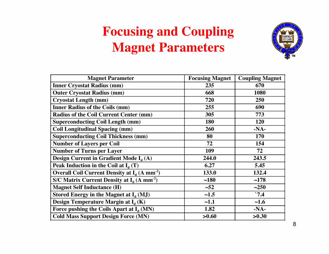
Focusing and CouplingMagnet Parameters
Magnet Parameter Focusing Magnet Coupling MagnetInner Cryostat Radius (mm) 235 670Outer Cryostat Radius (mm) 668 1080Cryostat Length (mm) 720 250Inner Radius of the Coils (mm) 255 690Radius of the Coil Current Center (mm) 305 773Superconducting Coil Length (mm) 180 120Coil Longitudinal Spacing (mm) 260 -NA-Superconducting Coil Thickness (mm) 80 170Number of Layers per Coil 72 154Number of Turns per Layer 109 72Design Current in Gradient Mode Id (A) 244.0 243.5Peak Induction in the Coil at Id (T) 6.27 5.45Overall Coil Current Density at Id (A mm-2) 133.0 132.4S/C Matrix Current Density at Id (A mm-2) ~180 ~178Magnet Self Inductance (H) ~52 ~250Stored Energy in the Magnet at Id (MJ) ~1.5 `7.4Design Temperature Margin at Id (K) ~1.1 ~1.6Force pushing the Coils Apart at Id (MN) 1.82 -NA-Cold Mass Support Design Force (MN) >0.60 >0.30

9
Focusing and Coupling MagnetLoad Line
1098765432100
100
200
300
400
500
T = 3.4 KT = 4.2 KT = 5.0 KCouplingFocusing
Magnetic Induction at the Wire (T)
Con
duct
or C
urre
nt (A
)
4.4 K
240 MeV/c
200 MeV/c
5.0 K
4.2 K
3.4 K

10
Detector Magnet Module

11
Matching and DetectorMagnet Parameters
Parameter Match #1 Match #2 End #1 Center End #2
Coil Inner Radius (mm) 255 255 250 250 250
Coil Length (mm) 202 202 120 1260 120
Coil Thickness (mm) 50 73 116 50 149
Number of Layers 30 44 70 30 90
Turns per Layer 84 84 50 525 50
Design Current (A) 254.1 267.8 257.0 258.9 257.9
Overall Coil J (A mm-2) 63.4 67.1 64.6 64.7 64.9
Coil Self Inductance (H) 5.8 8.8 8.9 46.2 14.9
Coil Stored Energy (MJ) 0.13 0.32 0.29 1.55 0.50
Coil Peak Induction (T) 3.4 4.4 4.9 4.2 5.0
Temperature Margin (K) >2.5 >2.0 1.8 >2.0 1.8

12
MICE Channel on Axis Field Profile
Mice Channel Center
Focus Coils Focus Coils
Detector and Matching Coils
Coupling Coil

13
Magnet Power Supplies• Each of the focus coils has its own leads so that the magnet can
be changed from a gradient magnet to a straight solenoidmagnet. The focusing magnets will be powered by a single 300A, 10 V power supply. The charging time for the focusingmagnets is about 1.5 hours.
• Each coupling coil will have its own 10 V, 300 A power supply.The charging time will be about 2.4 hours.
• The detector end and center coils will be hooked is series andpowered by a single 300 A, 10 V power supply. The chargetime will be about 1 hour. End coil #1 will have a separate 100A, 5 V power supply to adjust its current for tuning. Each ofthe matching coils will be in series with its corresponding coilin the other module. They will have 300 A, 10 V powersupplies. The charge time will be about 30 minutes. Somesmall 100 A, 5V power supplies may be needed for tuning.

14
Magnet Quench Protection
• Each focus coil will be protected by a warm diode andresistor across its leads.
• The coupling coils will divided into three or four parts. Eachpart will have a cold diode and resistor across that part. Theresistor will cause another part of the coil to become normal.The coupling coil quench protection scheme is commonlyused in high field MRI magnets.
• The three detector coils in series will be protected by warmdiodes and resistors across their leads. The matching coilswill be protected by a warm diodes and resistors across theirleads.
• All of the magnets will be protected in part by quench backfrom the magnet winding mandrel.

15
MICE Magnet Refrigeration
• The MICE magnet coil will be cooled by conduction fromthe winding mandrel and support structure. The mandreland the support structure will be cooled by two-phasehelium at 4.4 K flowing in tubes attached to these parts.
• About 70 W of 4.4 K refrigeration are needed to cool theseven magnet modules for MICE. The refrigeration isdominated by the heat leaks to the control dewar, transferlines, bayonets, and valves.
• Cooling for the magnet shields and leads comes from aseparate helium circuit that enters from the refrigerator at14 K. HTS leads are used in all magnets between 4.4 Kand about 50 K.

16
Some MICE Magnet Safety Issues
• The coupling solenoid leads and the detector magnet leadsare located outside of the hydrogen safety zone. Only thefocusing magnet leads may be located within a hydrogensafety zone.
• Since the magnet are cooled by force two-phase helium intubes, a magnet quench causes a minimal amount ofhelium to be released. The venting of this helium can berestricted to a point that is outside of the MICE shielding.
• The cryostat vacuum vessels all have relief devices that willopen in the event of pressure buildup in the vacuum space.
• The handling of cryogenic fluids and cold transfer lineswill be done by trained personnel using standard safetyprocedures for handling liquid helium prescribed by RAL.

17
Focusing Magnet and HydrogenSafety Issues
• If possible, the leads and cables for the focusing solenoidswill be located outside of the hydrogen safety zone. If theleads and cables can be located outside of the hydrogenzone, normal voltage protection standards can be applied.
• If the focusing coil leads and cables are within a hydrogensafety zone, they will have to be shielded using a cover ofan inert gas such as argon. Sparking must not occur in aregion where hydrogen gas can accumulate.
• Instrumentation wires for the focusing solenoids must belocated outside of the hydrogen safety zone if possible.
• The eddy currents from a focusing magnet quench doesnot cause hydrogen venting.

18
Concluding Comments
• Each of the magnet modules has its own insulating vacuumvessel. None of the magnets share a common vacuum withany of the other components of MICE.
• The cryogenic system has a minimum amount of liquidhelium within it. The helium that is in the magnets is intubes. The only pool of helium is in the control cryostat,which can be a commercial certified dewar.
• The magnet quench protection system will limit the voltagesseen at the magnet leads to about 10 volts.
• Only the focusing magnets are in a hydrogen area. A quenchof this magnet does not cause a general release of hydrogen.The major safety concern is the location of the magnet leads.