
Supercapacitor electrode materials: nanostructures from 0 ...
30
Energy & Environmental Science www.rsc.org/ees ISSN 1754-5692 REVIEW ARTICLE Jayan Thomas et al. Supercapacitor electrode materials: nanostructures from 0 to 3 dimensions Volume 8 Number 3 March 2015 Pages 677–1048
Transcript of Supercapacitor electrode materials: nanostructures from 0 ...

Energy &Environmental Sciencewww.rsc.org/ees
ISSN 1754-5692
REVIEW ARTICLEJayan Thomas et al.Supercapacitor electrode materials: nanostructures from 0 to 3 dimensions
Volume 8 Number 3 March 2015 Pages 677–1048

Energy &EnvironmentalScience
REVIEW
Ope
n A
cces
s A
rtic
le. P
ublis
hed
on 0
3 D
ecem
ber
2014
. Dow
nloa
ded
on 1
/2/2
022
4:33
:23
AM
. T
his
artic
le is
lice
nsed
und
er a
Cre
ativ
e C
omm
ons
Attr
ibut
ion
3.0
Unp
orte
d L
icen
ce.
View Article OnlineView Journal | View Issue
Supercapacitor e
NanoScience Technology Center (NSTC),
Engineering, Department of Physics, Depart
Photons, University of Central Florida, O
[email protected]; Fax: +1 407 882 2819; T
Cite this: Energy Environ. Sci., 2015, 8,702
Received 11th October 2014Accepted 28th November 2014
DOI: 10.1039/c4ee03229b
www.rsc.org/ees
702 | Energy Environ. Sci., 2015, 8, 702
lectrodematerials: nanostructuresfrom 0 to 3 dimensions
Zenan Yu, Laurene Tetard, Lei Zhai and Jayan Thomas*
Supercapacitors have drawn considerable attention in recent years due to their high specific power, long
cycle life, and ability to bridge the power/energy gap between conventional capacitors and batteries/fuel
cells. Nanostructured electrode materials have demonstrated superior electrochemical properties in
producing high-performance supercapacitors. In this review article, we describe the recent progress and
advances in designing nanostructured supercapacitor electrode materials based on various dimensions
ranging from zero to three. We highlight the effect of nanostructures on the properties of
supercapacitors including specific capacitance, rate capability and cycle stability, which may serve as a
guideline for the next generation of supercapacitor electrode design.
Broader context
The ever-growing global demand of energy together with the depletion of fossil fuels makes it critical to develop sustainable and renewable energy resources.Developing relevant energy storage systems (e.g. batteries and supercapacitors) is essential to utilizing sustainable and renewable energy resources. A super-capacitor is highly benecial in storing renewable energy. For example, when light is not shining or wind is not blowing, the energy needs to be stored in deviceslike batteries and supercapacitors. Among the efforts of building efficient supercapacitors, electrodematerials with rational nanostructured designs have offeredmajor improvements in performance over the past several years. This review article is intended to examine recent progress in nanostructuring supercapacitorelectrode materials, highlighting the fundamental understanding of the relationship between structural properties and electrochemical performances, as wellas an outlook on the next generation of nanostructured supercapacitor electrodes design.
1 Introduction
Before a ray of sun light peeked through the curtain and shinedon John's face, everything was perfect for a quiet morning.Suddenly jumping off the bed, “Oh, my, I forgot to set the alarmlast night.” He got dressed and rushed to his electric car; “LOWBATTERY” exclaimed John, “wish I could charge it up in a fewminutes.” As a matter of fact, such energy storage technolo-gies like supercapacitors which can charge very quickly havebeen around for decades, but their low energy densities haveheld them back in many such applications. The ever growingdemand for energy urges researchers to look for new materialsand processes to develop highly improved energy storagedevices. Among energy storage systems, supercapacitors havedrawn considerable attention during recent years due to theirfast charge–discharge characteristics, high power density, andexcellent cycle stability. Currently, supercapacitors are usedalong with batteries to provide the additional power required inmany applications. However, they cannot be used as stand-alone units in these applications since their energy density is
Department of Materials Science and
ment of Chemistry, College of Optics and
rlando, FL 32826, USA. E-mail: Jayan.
el: +1 407 882 0196
–730
inferior to that of batteries. For example, commercially avail-able supercapacitors can provide energy densities of less than10 W h Kg�1 whereas Li-ion batteries can provide energydensities of more than 180 W h Kg�1.1,2 Nevertheless, thepower density and cycle life of supercapacitors are far superiorto those of Li-ion batteries. At present, the scientic commu-nity is striving to considerably improve the energy and powerdensity of supercapacitors by developing new electrode mate-rials and electrolytes, and ingenious device design.
Achieving noteworthy improvements in supercapacitorperformances by means of better electrode materials togetherwith low-cost and environment-friendly production, requires adeep fundamental understanding of the charge storage mech-anisms, transport pathways of electrons and ions, and electro-chemically active sites. Advances in nanomaterials, idealcandidates for improved ion adsorption or faster surface redoxreactions, have fostered extensive research efforts toward theenhancement of electrochemically active sites for chargetransfer and controlled ionic and electronic transport at smalldiffusion length scales.
Supercapacitors are generally classied into two types basedon their storage mechanism, the electrochemical double layercapacitors (EDLCs) and pseudocapacitors. EDLCs physicallystore charges via reversible ion adsorption at the electrode–electrolyte interface, while pseudocapacitors chemically store
This journal is © The Royal Society of Chemistry 2015

Review Energy & Environmental Science
Ope
n A
cces
s A
rtic
le. P
ublis
hed
on 0
3 D
ecem
ber
2014
. Dow
nloa
ded
on 1
/2/2
022
4:33
:23
AM
. T
his
artic
le is
lice
nsed
und
er a
Cre
ativ
e C
omm
ons
Attr
ibut
ion
3.0
Unp
orte
d L
icen
ce.
View Article Online
their charges via redox reaction at the vicinity (a few nanome-ters) of the surface. Typically, electrode materials for EDLCs aremade of carbon-based materials (including activated carbon,carbon nanotubes, graphene, etc.), while that for pseudocapa-citors are transition metal oxides (e.g. RuO2, MnO2, CoOx, NiO,Fe2O3, etc.) and conducting polymers (e.g. polypyrrole, poly-aniline, poly(3,4-ethylenedioxythiophene), etc.).
The criteria for designing a high-performance supercapacitorelectrode include high specic capacitance (energy stored perunit mass, volume, or area of active materials), large rate capa-bility (capacitance retention at high scan rate or current density),and high cycle stability. In addition, the toxicity and cost of theactive materials used in an electrode design should be taken intoaccount as well. Therefore, in order to realize a high-perfor-mance supercapacitor electrode, factors that determine thespecic capacitance, rate capability, and cycle stability need tobe mentioned here. (1) Surface area: Since charges are stored onthe surface of the supercapacitor electrodes, an electrode with a
Zenan Yu is a Ph.D. student inthe Department of MaterialsScience and Engineering atUniversity of Central Florida. Hereceived his B.S. degree in Elec-tronic Science and Technologyfrom Shanghai University in2011. Under the supervision ofProfessor Jayan Thomas, hisresearch interests mainly focuson the design, synthesis andapplications of nanostructuredmaterials for supercapacitors.
Laurene Tetard is an assistantprofessor at the NanoScienceTechnology Center (NSTC) andDepartment of Physics. Shereceived her B.S. and M.S. fromthe University of Burgundy inFrance and completed her Ph.D.with Professor Thundat at theUniversity of Tennessee, Knox-ville in 2010. She was a EugeneP. Wigner Fellow at the OakRidge National Laboratory from2011 to 2013 before joined the
University of Central Florida in 2013. Her current research interestincludes innovative nanoscale characterization of energy-relatedmaterials including two dimensional materials and so matter.
This journal is © The Royal Society of Chemistry 2015
higher surface area leads to an improved specic capacitance.Nanostructuring of electrode materials is a feasible method toconsiderably improve the surface area of the electrodes. (2)Electronic and ionic conductivity: As specic capacitance andrate capability are considerably dependent on both electronicand ionic conductivity, a high electronic and ionic conductivitywill help to maintain the rectangular nature of cyclic voltam-metry (CV) curve and symmetricity of galvanostatic charging–discharging (GCD) curves. They also reduce the specic capaci-tance losses as scan rates/current densities are increased.Typical approaches to enhance the electronic conductivityinclude binder-free electrode design and nanostructured currentcollector design to provide efficient electron pathways for chargetransport. To increase the ionic conductivity, precise control ofpore size and prudent design strategies are used (e.g.more openstructures for ion transport). (3) Mechanical and chemicalstability: The cycle stability is greatly inuenced by themechanical and chemical stability of electrode materials during
Lei Zhai is an associateprofessor at the NanoScienceTechnology Center (NSTC) andDepartment of Chemistry. Hereceived his Ph.D. from CarnegieMellon University in 2002 andworked as a postdoctoralresearch associated at Massa-chusetts Institute of Technologybefore he joined the University ofCentral Florida in 2005. He is arecipient of NSF CAREER Awardand a Scialog Fellow of Research
Corporation for Science Advancement. His research focuses onconjugated polymers and composites for energy conversion andstorage, surface science and engineering, and polymer derivedceramics.
Jayan Thomas is an assistantprofessor at the NanoScienceTechnology Center (NSTC),College of Optics and Photonics(CREOL) and College of Engi-neering and Computer Scienceat the University of CentralFlorida (UCF). Aer receivingPh.D. from Cochin University ofScience and Technology inIndia, he joined College ofOptical Sciences, University ofArizona in 2001 as a research
faculty. He moved to UCF in 2011 and is currently working on thedevelopment of supercapacitors, photorefractive polymers andsolar cells. He is a recipient of NSF CAREER award, VEECO's 2010best nanotechnology innovation award and WTN World Tech-nology (Energy) Award-2014 sponsored by FORTUNE and TIME.
Energy Environ. Sci., 2015, 8, 702–730 | 703

Energy & Environmental Science Review
Ope
n A
cces
s A
rtic
le. P
ublis
hed
on 0
3 D
ecem
ber
2014
. Dow
nloa
ded
on 1
/2/2
022
4:33
:23
AM
. T
his
artic
le is
lice
nsed
und
er a
Cre
ativ
e C
omm
ons
Attr
ibut
ion
3.0
Unp
orte
d L
icen
ce.
View Article Online
cycling. Phase change, dissolution, and side reaction of activematerials are the major reasons for causing cycle instability.Sensible electrode surface protectionmay substantially boost thecycle stability. In addition to investigating new electrode mate-rials, electrode design with nanostructures offers a promisingavenue to fulll high-performance supercapacitors. This isbecause the aforementioned factors can be effectively manipu-lated by a nanostructured design, which will be discussed indetail in the following sections.
Typically, nanomaterials can be classied into zero dimen-sional (0D), one dimensional (1D), two dimensional (2D) andthree dimensional (3D) categories.3–5 Particles which are more orless spherical in shape like fullerenes, quantum dots, nano-onions, nanoparticles, etc. are considered as 0D. Nanostructureswith 1D are interesting due to their dimensionality dependenceon its functional properties. They include nanotubes, nano-bers, nanowires, nanopillars, nanoribbons and nanobelts.Typically, materials with a thickness of a few atomic layers andwith the other two dimensions beyond the nanometric sizerange are considered as 2Dmaterials. Graphene andmany otherlayered van der Waals solids like MoS2, CaGe2 and CaSi2, fallunder the 2D category. Materials with three dimensions beyondthe nanometric size range but still preserve the advantages ofnano size effect are regarded as 3D materials. Mesoporouscarbon and graphene aerogel fall under 3D category.
Even though there are several reviews describing the mate-rial aspects of supercapacitor electrodes,2,6–9 a comprehensivereview of 0D, 1D, 2D and 3D materials used only in super-capacitors is still lacking. Although Wu and co-authors havereported the dimensional study of electrodes for 0 to 3D,10 theyonly focused on carbon–metal oxide composite electrodes from0 to 3D. This review covers a much broader range of electrodematerials. In recent years, a range of materials congurationsranging from 0D particles to 3D nanostructured frameworkshave been developed and tested in supercapacitors devices. Thisreview is aiming to ll this gap and provide the readers a clearidea about the performance of these materials as electrodes inelectrochemical supercapacitors. Fig. 1 summarized the keypoints of electrode materials from 0 to 3D and a detaileddiscussion is given in the following sections.
2 0D nanostructures
According to the strict denition, 0D nanostructures arespherical particles that have three dimensions constrained onthe nanoscale (usually 1–100 nm). Nevertheless, particles withdiameters up to 1 mm are usually regarded as nanoparticles aswell, as the benet provided by the effect of their small size hasbeen observed for this size range. In this section, threesubcategories of 0D nanostructures used as electrodes insupercapacitors are considered, viz., solid, hollow, and core–shell 0D nanostructures.
2.1 Solid 0D nanostructures
As the foundation of 0D nanostructures, solid nanoparticles(nanospheres) are intensely investigated for designing
704 | Energy Environ. Sci., 2015, 8, 702–730
supercapacitor electrodes. Carbon materials (e.g. activatedcarbon,11 carbon nanospheres,12 and mesoporous carbon13,14)and transition metal oxides (e.g. MnO2,15,16 NiO,17–19 Fe3O4,20
etc.) have been widely fabricated into solid nanoparticles forelectrode materials. Among carbon materials, activatedcarbons (ACs) are distinct due to their high surface area (up to3000 m2 g�1) and economical fabrication process. In addition,ACs propose a wide range of pore size distribution includingmicropores (<2 nm), mesopores (2–50 nm), and macropores(>50 nm).21 ACs are generally produced by either physical orchemical activation of versatile carbonaceous precursors suchas wood, coal, nutshell, and so forth. Larger surface area isusually expected to result in a higher specic capacitance.However, even with a surface area of up to 3000 m2 g�1, onlysmall specic capacitance (<10 mF cm�2) could be obtained withACs.1 This is due to the fact that specic capacitance is not onlydetermined by surface area but also by other parameters such aspore size distribution, pore shape and structure, accessibility ofthe electrolyte, and electrical conductivity.6 Therefore, an idealdesign of ACs should meet at least two requirements: (1) largesurface area for the enhancement of electrochemically activesites and (2) suitable pore size and structure for the trans-portation of ions in the electrolyte. In addition to ACs, Gogotsi,Simon, and their co-workers have prepared onion-like carbon byannealing nanodiamond powder at 1800 �C.22,23 The carbononions were found to possess a moderate specic surface area(�500 m2 g�1) compared to ACs; however, the surface can befully accessed by ions (Fig. 2). As a result, micro-supercapacitorsbased on these onion-like carbons showed�70% rate capabilityfrom 1 to 100 V s�1 and an excellent relaxation time constant(26 ms) compared to that of activated carbon (700 ms).
The above mentioned criteria for designing ideal ACs arealso applicable to transition metal oxide nanoparticles inpseudocapacitors as they rely on fast surface redox reactions.Additionally, as most of the transition metal oxides suffer frompoor electrical conductivity, enhancing the bulk electricalconductivity should also be taken into account. For example,Chen and co-workers have fabricated nanoporous metal/oxidehybrid supercapacitor electrodes in order to enhance the elec-trical conductivity of MnO2.24 In this method, conductivenanoporous gold was rst produced by de-alloying Ag65Au35using HNO3, followed by growing nanocrystalline MnO2 (with agrain size of �5 nm) into the nanopores. The resulting nano-porous Au/MnO2 supercapacitor electrode showed a highspecic capacitance of �1145 F g�1 at 50 mV s�1, which can beattributed to nanoporous gold that allows easy and efficientaccess to both electrons and ions. Recent advances in usingperovskite materials for solar energy harvesting have greatlystimulated the enthusiasm of researchers to exploit thesematerials for other potential elds. Lately, Stevenson, Johnston,and co-workers have prepared LaMnO3 nanoparticles viareverse-phase hydrolysis method as supercapacitor electrodematerial.25 Fig. 3a shows an ideal LaMnO3 cubic perovskitestructure, where lanthanum atom locates at body centeredposition, manganese atoms at cubic corner positions, andoxygen atoms at mid-edge positions respectively. The dark-eldSEM image (Fig. 3b) presents the small (�20–50 nm)
This journal is © The Royal Society of Chemistry 2015
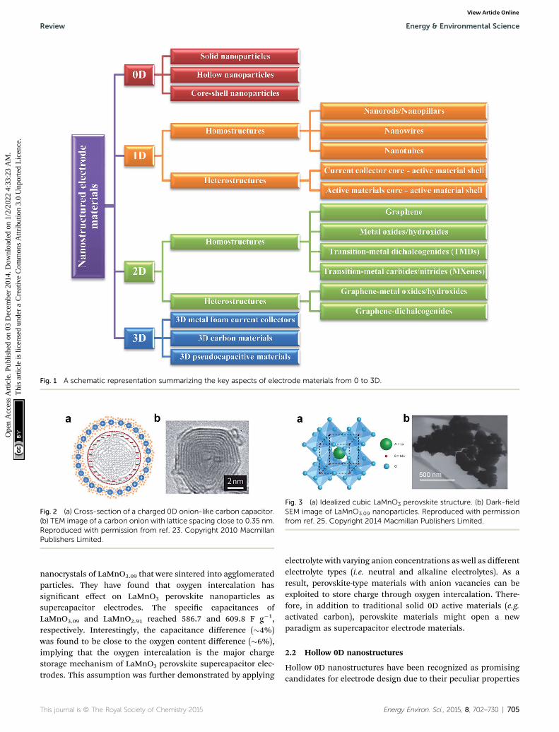
Fig. 1 A schematic representation summarizing the key aspects of electrode materials from 0 to 3D.
Fig. 2 (a) Cross-section of a charged 0D onion-like carbon capacitor.(b) TEM image of a carbon onion with lattice spacing close to 0.35 nm.Reproduced with permission from ref. 23. Copyright 2010 MacmillanPublishers Limited.
Fig. 3 (a) Idealized cubic LaMnO3 perovskite structure. (b) Dark-fieldSEM image of LaMnO3.09 nanoparticles. Reproduced with permissionfrom ref. 25. Copyright 2014 Macmillan Publishers Limited.
Review Energy & Environmental Science
Ope
n A
cces
s A
rtic
le. P
ublis
hed
on 0
3 D
ecem
ber
2014
. Dow
nloa
ded
on 1
/2/2
022
4:33
:23
AM
. T
his
artic
le is
lice
nsed
und
er a
Cre
ativ
e C
omm
ons
Attr
ibut
ion
3.0
Unp
orte
d L
icen
ce.
View Article Online
nanocrystals of LaMnO3.09 that were sintered into agglomeratedparticles. They have found that oxygen intercalation hassignicant effect on LaMnO3 perovskite nanoparticles assupercapacitor electrodes. The specic capacitances ofLaMnO3.09 and LaMnO2.91 reached 586.7 and 609.8 F g�1,respectively. Interestingly, the capacitance difference (�4%)was found to be close to the oxygen content difference (�6%),implying that the oxygen intercalation is the major chargestorage mechanism of LaMnO3 perovskite supercapacitor elec-trodes. This assumption was further demonstrated by applying
This journal is © The Royal Society of Chemistry 2015
electrolyte with varying anion concentrations as well as differentelectrolyte types (i.e. neutral and alkaline electrolytes). As aresult, perovskite-type materials with anion vacancies can beexploited to store charge through oxygen intercalation. There-fore, in addition to traditional solid 0D active materials (e.g.activated carbon), perovskite materials might open a newparadigm as supercapacitor electrode materials.
2.2 Hollow 0D nanostructures
Hollow 0D nanostructures have been recognized as promisingcandidates for electrode design due to their peculiar properties
Energy Environ. Sci., 2015, 8, 702–730 | 705

Fig. 4 (a) Schematic of synthesizing multishelled NiO hollow nano-spheres using LBL self-assembly. TEM images show NiO hollownanospheres with (a) single-shell, (b) double-shells, and (c) triple-shells. Reproduced with permission from ref. 34. Copyright 2014Elsevier.
Energy & Environmental Science Review
Ope
n A
cces
s A
rtic
le. P
ublis
hed
on 0
3 D
ecem
ber
2014
. Dow
nloa
ded
on 1
/2/2
022
4:33
:23
AM
. T
his
artic
le is
lice
nsed
und
er a
Cre
ativ
e C
omm
ons
Attr
ibut
ion
3.0
Unp
orte
d L
icen
ce.
View Article Online
such as low density, high surface-to-volume ratio and shortenedpathways for transporting both mass and charges.26 Hollow 0Dnanostructures are generally synthesized via three distinctapproaches: hard templating, so templating, and template-free methods. Among them, hard templating methods havebeen widely adopted because of their remarkable advantages incontrolling the size, shape, and structure of the products.27
Typically, a single-shelled hollow nanosphere is created bycoating a thin layer of precursor materials onto a spherical hardtemplate (e.g. silica spheres, polystyrene colloid spheres,carbonaceous spheres, etc.), followed by removing the templateeither by calcination or by chemical etching. For example, Yangand co-workers reported the synthesis of hollow carbon nano-spheres by carbonizing its hollow nanosphere precursorobtained through a silica sphere-assisted hard templatingmethod.28 The resulting hollow carbon nanospheres showed ahigh surface area (1704 m2 g�1), large bimodal mesopores(6.4 and 3.1 nm), and large pore volumes (1.6 cm3 g�1). Withsuch a design, a specic capacitance of 251 F g�1 at 50 mV s�1
was achieved for the hollow carbon nanospheres. Hollow 0Dstructures based on other electrode materials such as MnO2,29,30
NiO,31,32 NiS,33 etc. have been investigated as well.In addition to single shelled hollow 0D nanostructures,
multiple shelled samples have also shown fascinating charac-teristics (e.g. substantially improved surface-to-volume-ratio) forefficient electrode material design. Similarly, electrodematerialslike NiO,34 Co3O4,35 and Fe2O3,36 have been successfully fabri-cated into multi-shelled structures. For example, Zhang and co-workers reported the synthesis of NiO hollow nanospheres vialayer-by-layer (LBL) self-assembly for supercapacitor applica-tion.34 In their method, the number of shells was directlydetermined by the cycles of immersion–precipitation processbefore removing the carbonaceous template via calcination(Fig. 4a). Single, double, and triple shelled NiO nanosphereswere prepared by repeating the immersion–precipitation processfor 0, 1, and 2 times (Fig. 4b and c). The double-shelled NiOnanospheres exhibited the highest surface area (92.00 m2 g�1),which ascribes to their more loosely-packed structure comparedto their single and triple shelled counterparts. As a result, thedouble shelled NiO nanospheres showed the most enhance-ment in specic capacitance (612.5 F g�1). Since many otherpromising electrode materials have not been fabricated into 0Dmulti shelled structures, much effort still needs to be dedicatedin the future.
Fig. 5 (a) FESEM and (b) TEM images of HCS–PANI. (c) FESEM and (d)TEM images of GHCS–MnO2. Reproduced with permission from ref.37 and 38. Copyright: 2010 American Chemical Society and 2012 TheRoyal Society of Chemistry.
2.3 Core–shell 0D nanostructures
Core–shell 0D nanostructures oen refer to a solid or hollownanoparticle coated with a thin shell. Combining faradaic andnon-faradaic materials into core–shell 0D nanostructures offerconsiderable advantages including enhanced electricalconductivity, less agglomeration, robust chemical andmechanical stability, etc.37–40 For example, Zhao and co-workershave grown conducting polymer (polyaniline (PANI)) on hollowcarbon spheres as supercapacitor electrode materials.37 Hollowcarbon spheres (HCS) with high specic area (2239 m2 g�1) wererst prepared using ferrocene as the carbon precursor and silica
706 | Energy Environ. Sci., 2015, 8, 702–730
spheres as the template. PANI was then conformally grown onthe surface of the HCS by polymerizing aniline at roomtemperature for 12 h (Fig. 5a and b). HCS–PANI core–shellstructures with an optimized content of PANI showed a speciccapacitance of 525 F g�1, which is almost two times greater thanthat of pristine HCS (268 F g�1). However, the rate capability ofHCS–PANI decayed with increasing PANI content, which can beattributed to the pore blockage due to the reduced accessibilityof electrolyte ions. Zhao's group also synthesized core–shellnanoparticles with carbon core and MnO2 shell by direct redoxreaction between graphitic hollow carbon spheres (GHCS) andKMnO4 solution at 70 �C (Fig. 5c and d).38 The as-prepared
This journal is © The Royal Society of Chemistry 2015

Review Energy & Environmental Science
Ope
n A
cces
s A
rtic
le. P
ublis
hed
on 0
3 D
ecem
ber
2014
. Dow
nloa
ded
on 1
/2/2
022
4:33
:23
AM
. T
his
artic
le is
lice
nsed
und
er a
Cre
ativ
e C
omm
ons
Attr
ibut
ion
3.0
Unp
orte
d L
icen
ce.
View Article Online
GHCS–MnO2 core–shell nanostructures showed a maximumspecic capacitance of 190 F g�1 at 0.1 A g�1 with an optimizedMnO2 content (64 wt%), more than two times higher than thatof pristine GHCS (95 F g�1). Moreover, the GHCS–MnO2 core–shell nanostructures maintained 55% capacitance retentionwhile current density increased from 0.1 to 10 A g�1, indicatinga porous structure of MnO2 shell was formed to provide efficientdiffusion pathway for electrolyte ions.
3 1D nanostructures
1D nanostructures are slivers of material with two dimensionsconstrained on nanoscale.41 They have been extensively studiedfor the design of electrode materials for supercapacitors due totheir unique and superior chemical and physical properties.42–47
For instance, the longitudinal axis of 1D nanostructures canprovide efficient transport pathway for both electrons andions,48 while maintaining the similar benets of 0D nano-structures in the two nanoscale dimensions. In this section, weplace 1D nanostructures into two major categories: homo-structures and heterostructures.
Fig. 6 (a) Fabrication of carbon nanostructures by SNAP method. (b)SEM images of top view and side view (inset) of polymer nanopillars. (c)SEM images of top view and side view (inset) of carbon nanopillars.Reproduced with permission from ref. 51. Copyright 2013 WILEY-VCHVerlag GmbH & Co. KGaA, Weinheim.
3.1 1D homostructures
1D homostructures are structures with only one singularstructure such as nanorods, nanowires, nanotubes, etc. Theycan be divided into three groups, namely, nanorods/nanopilarswith aspect ratios (length/diameter) less than 10, nanowireswith aspect ratios more than 10, and nanotubes with hollowinteriors.49 The methods for synthesizing 1D homostructuresare versatile and can generally be divided into two major types,template-assisted and template-free methods. For template-assisted methods, sacricial templates (e.g. AAO templates) arecommonly used to shape the initial structure, followed by theremoval of the templates with an acidic or basic solution. Fortemplate-free methods, various approaches like hydrothermalsynthesis, chemical vapor deposition (CVD), and electrodepo-sition are generally employed to directly grow 1D homo-structures. Recently, vertical growth of active material on theconductive substrate either by a “bottom-up” or “top-down”method has become one of the most promising electrodedesign approaches. Such a design guarantees efficient transportof electrons between current collector and active materialbecause of the binder-free design. It also enables fast transfer ofions between electrolyte and active materials because of theavailable void space between adjacent nanostructures.
3.1.1 Nanorods/nanopillars. Although the moderate aspectratio of nanorods/nanopillars limits the enhancement of surfacearea compared to nanowires/nanobers, the signicantly lowerchances for individual nanorod/nanopillar to collapse on to itsneighboring structures making them more accessible to theelectrolyte, which effectively increases the ionic conductivity.
Tong and co-workers have reported oxygen-decient Fe2O3
nanorods as supercapacitor electrode material.50 Nanorod-likeFeOOH was rst hydrothermally synthesized in an aqueoussolution containing ferric chloride, sodium nitrate, andhydrogen chloride. Subsequently, the FeOOH nanorods were
This journal is © The Royal Society of Chemistry 2015
heated at high temperature in air and N2, separately, whichresulted in pristine Fe2O3 nanorods and oxygen-decient Fe2O3
nanorods. Interestingly, the oxygen-decient Fe2O3 nanorodsexhibited more than two times enhancement of the speciccapacitance (64.5 F g�1) than that of pristine Fe2O3. Thisphenomenon may be attributed to the existence of oxygenvacancies which considerably enhance the donor density and inturn improve the conductivity and reactivity of Fe2O3 nanorods.
Recently, Thomas and co-workers reported a facile methodto produce highly ordered carbon nanopillars as supercapacitorelectrodes.51 They rst developed a novel technique, called spin-on nanoimprinting (SNAP), to print highly ordered polymernanostructures.51–54 In a typical SNAP process, a thin layer ofpolymer solution was spin-coated on an e-beam etched nano-hole structured silicon mold, followed by curing and peeling offthe polymer from the template (Fig. 6a). The SNAP techniquewas demonstrated to be simple, quick, and cost-effective since itrequires just a spin coater and a pre-fabricated template. Theentire printing process can be completed within a few minutes,but can be performed at a much faster pace if automated.Moreover, a large-scale nanostructure can be easily obtained bystitching several printed structures next to each other. Unlikecommonly used sacricial template (e.g. AAO template), thistemplate can be re-used many times without any noticeabledegradation of nanostructures since all the polymer nanopillarscan easily be removed from the template. The carbon nanopillararrays were obtained upon post stabilization and carbonizationof the polymer nanostructures. Fig. 6b and c show the SEMimages of printed polyacrylonitrile (PAN) and carbon nanopillararray. The diameter and height of each carbon nanopillar is�95 nm and �200 nm, respectively. Signicantly, the speciccapacitance of the carbon nanopillar arrays (3.4 mF cm�2)showed considerable enhancement compared to that of aplanar carbon lm (0.05 mF cm�2).
Energy Environ. Sci., 2015, 8, 702–730 | 707

Energy & Environmental Science Review
Ope
n A
cces
s A
rtic
le. P
ublis
hed
on 0
3 D
ecem
ber
2014
. Dow
nloa
ded
on 1
/2/2
022
4:33
:23
AM
. T
his
artic
le is
lice
nsed
und
er a
Cre
ativ
e C
omm
ons
Attr
ibut
ion
3.0
Unp
orte
d L
icen
ce.
View Article Online
3.1.2 Nanowires. Nanowires have been widely studied aselectrode material due to their high aspect ratio that canprovide large surface area to store charges and an efficientpathway to transport charges. Taking PANI nanowires as anexample, Li and co-workers have synthesized vertically alignedPANI nanowires as supercapacitor electrodes by means ofelectrochemical deposition using AAO templates.55 The elec-trochemical deposition was carried out at a constant potentialof 0.75 V for 5000 s in an electrolyte solution containing anilineand sulfuric acid. PANI nanowire arrays were obtained uponremoving the AAO template in a 0.01 M NaOH solution. Thesesamples showed a specic capacitance of 1142 F g�1 at a currentdensity of 5 A g�1, with 5% capacitance fading aer 500 cycles.Regardless of the superior electrochemical performance ofPANI nanowires, the usage of AAO templates limits the practi-cality of this fabrication process for large scale production sincea new AAO template is required for every array of nanostructuresproduced. Lately, Wei and co-workers reported a facile one-steptemplate-free approach to synthesize PANI nanowire arrays.56 Intheir method, PANI nanowire could directly be electro-polymerized by a simple galvanostatic deposition process at aconstant current of 0.01 mA cm�2 for 1 h. Consequently, the as-prepared PANI nanowire arrays showed 950 F g�1 at a currentdensity of 1 A g�1 and 16% loss aer 500 cycles.
Lately, a ternary metallic oxide, spinel nickel cobaltite(NiCo2O4), has attracted substantial attention due to its highconductivity (more than two orders of magnitude higher thansingle NiO or Co3O4) and multiple oxide states that enable richredox reactions originating from both nickel and cobaltions.57,58 For example, Lou and co-workers have successfullygrown NiCo2O4 nanoneedle arrays directly on conductivesubstrates as supercapacitor electrodes.59 In their syntheticprocess, a conductive substrate was rst immersed into asolution containing nickel nitrite, cobalt nitrite, ethanol, andwater in an appropriate ratio and heated to 85 �C for 8 h, fol-lowed by annealing at 250 �C for 90 min. Remarkably, theNiCo2O4 nanoneedle arrays showed a capacitance of 1118.6 Fg�1 and about 10.6% loss in capacitance aer 2000 cycles.
3.1.3 Nanotubes. Compared to solid nanostructures (e.g.nanowires), tubular nanostructures typically offer higher surfacearea with less utilization of mass, resulting in more gravimetricspecic capacitance. Nanotubes are usually synthesized viatemplate-assisted method, CVD, hydrothermal method, etc. Fortemplate-assisted method, nanotubes can be easily prepared bypartially inltrating the nanotube forming material into a nano-porous template. This is due to the fact that materials preferen-tially anchor on the walls of nanochannels at their earlyinltrating stage. Therefore, it is critical to manipulate the inl-tration process in order to produce tubular nanostructures. Forexample, MnO2 nanotube arrays were synthesized using AAOtemplate via electrochemical deposition for 10 min; whereasMnO2 nanowire arrays were obtained aer 60 min of deposition.60
TheMnO2 nanotube arrays showed a specic capacitance of 320 Fg�1, while only 101 F g�1 was measured for the nanowire arrays.Using the same strategy, other electrode materials were synthe-sized with tubular nanostructure such as RuO2,61 PEDOT,62 etc.
708 | Energy Environ. Sci., 2015, 8, 702–730
The discovery of carbon nanotubes (CNTs) has led to severalapplications in energy storage eld. CNTs as supercapacitorelectrode materials, and especially vertically aligned CNTs directlygrown on conductive substrates, have drawn remarkable attentiondue to their moderate to high surface area (120–500 m2 g�1),porous structure, superior electronic conductivity, and excellentmechanical and thermal stability. Ajayan and co-workers havegrown aligned CNTs (400 mm long) on metal alloy (Inconel) usingvapour-phase catalyst delivery.63 The CV curves showed rectan-gular and symmetric shape even at a scan rate of 1000 mV s�1,suggesting ideal capacitive behavior and low contact resistancebetween the CNTs and the substrate. The specic capacitance of asupercapacitor based on these vertically aligned CNT arrays wasfound to be 18 F g�1. Iijima and co-workers reported a method toprepare densely packed and aligned CNTs using zipping effect assupercapacitor electrode material.64 The specic capacitance ofthe aligned CNTs showed 80 F g�1, which is roughly twice thevalue of 45 F g�1 for the entangled CNTs. Recently, Kim and co-worker have grown vertically aligned CNTs directly on conductivecarbon papers using an Al/Fe catalyst via water-assisted CVD.65
These aligned CNTs exhibited a specic capacitance of about200 F g�1 at 20 A g�1.
3.2 1D heterostructures
Unlike homostructures, heterostructures usually consist ofmore than one component. One major advantage of usingheterostructured electrode design is the synergic improvementof intrinsic properties of each component for better electricalconductivity, faster ionic transport, greater electrochemicalreversibility and cycle stability, and improved mechanicalstability. Owing to these advantages, 1D heterostructures arecurrently considered as one of the potential candidates for thenext generation electrode designs.
3.2.1 Core–shell 1D heterostructures. Core–shell 1D het-erostructures oen refer to a 1D nanostructure (e.g. nanorod,nanowire, nanotube, etc) coated with a thin shell. Amongvarious heterostructures, core–shell heterostructures havereceived considerable attentions due to their unique structuralproperties that can effectively decline the surface energy whichreduces the aggregation possibility of active materials as wellas relieves side reaction between electrode and electrolyte,resulting in better reversibility and cycle stability of electrodes.Therefore, rational synthesis of advanced core–shell hetero-structures with fascinating synergetic properties offers apromising approach to improve electrochemical performance.Typically, most of the core–shell heterostructures are preparedby initially creating a 1D nanostructured core backbone, fol-lowed by sheathing the shell materials. Various methods havebeen explored in order to obtain such advanced congurationincluding sputtering, electrochemical deposition, hydro-thermal synthesis, CVD, electrospinning, etc. Due to theversatile combinations of electrode materials in terms of coreand shell in a core–shell design, herein they are simply grou-ped into two categories: (1) current collector core – activematerial shell and (2) active material core – active materialshell. For the convenience of discussion, we denote material A
This journal is © The Royal Society of Chemistry 2015
Review Energy & Environmental Science
Ope
n A
cces
s A
rtic
le. P
ublis
hed
on 0
3 D
ecem
ber
2014
. Dow
nloa
ded
on 1
/2/2
022
4:33
:23
AM
. T
his
artic
le is
lice
nsed
und
er a
Cre
ativ
e C
omm
ons
Attr
ibut
ion
3.0
Unp
orte
d L
icen
ce.
View Article Online
(core) and material B (shell) as A@B for the remainder of themanuscript.
(1) Current collector core – active material shell. In thisconguration, 1D nanostructured current collector core canprovide shortened pathways for electron transport, whicheffectively enhances the available electrochemically active sites.Owing to the high electrical conductivity as well as excellentmechanical stability, metals have been selected as pivotalcurrent collector candidates. When metals are forged into 1Dnanostructures like nanowires or nanotubes, active materialscan be deposited onto these 1Dmetal nanostructures and henceform core–shell 1D nanostructured electrode materials. Thereare several approaches to synthesize 1D metal nanostructuresincluding template-assisted preparation,66–69 so solution pro-cessing,49,70,71 vapor phase synthesis,72–74 and self-assem-bling.75,76 Among them, template-assisted preparation is themost intensively studied method for 1D metal nanostructuresynthesis. Particularly, 1D metal nanostructures can be fullledby either shaping with the help of sacricial templates (e.g.AAO) or directly coating active material on supercapacitive-inactive 1D nanostructures. For the former case, a pioneeringwork led by Teberna and co-workers reported Cu nanowire arrayprepared using AAO template as current collector, which wassubsequently deposited with active materials (Fe3O4).69
Following a similar concept, other works have been demon-strated such as Ni@MnO2,77,78 Ni@NiO,79 Au@MnO2,80
Ni@Co3O4,81 Mn@MnO2,82 etc. For the latter, since the inert
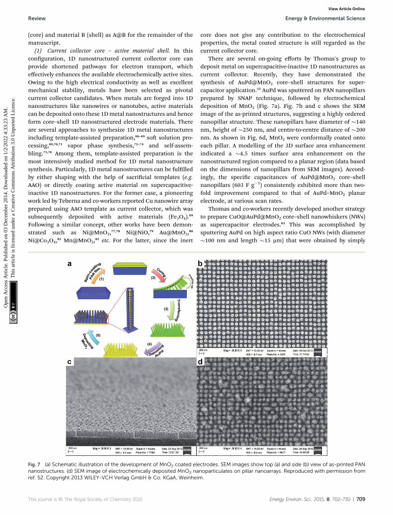
Fig. 7 (a) Schematic illustration of the development of MnO2 coated elenanostructures. (d) SEM image of electrochemically deposited MnO2 naref. 52. Copyright 2013 WILEY-VCH Verlag GmbH & Co. KGaA, Weinheim
This journal is © The Royal Society of Chemistry 2015
core does not give any contribution to the electrochemicalproperties, the metal coated structure is still regarded as thecurrent collector core.
There are several on-going efforts by Thomas's group todeposit metal on supercapacitive-inactive 1D nanostructures ascurrent collector. Recently, they have demonstrated thesynthesis of AuPd@MnO2 core–shell structures for super-capacitor application.52 AuPd was sputtered on PAN nanopillarsprepared by SNAP technique, followed by electrochemicaldeposition of MnO2 (Fig. 7a). Fig. 7b and c shows the SEMimage of the as-printed structures, suggesting a highly orderednanopillar structure. These nanopillars have diameter of �140nm, height of �250 nm, and centre-to-centre distance of �200nm. As shown in Fig. 6d, MnO2 were conformally coated ontoeach pillar. A modelling of the 3D surface area enhancementindicated a �4.5 times surface area enhancement on thenanostructured region compared to a planar region (data basedon the dimensions of nanopillars from SEM images). Accord-ingly, the specic capacitances of AuPd@MnO2 core–shellnanopillars (603 F g�1) consistently exhibited more than two-fold improvement compared to that of AuPd–MnO2 planarelectrode, at various scan rates.
Thomas and co-workers recently developed another strategyto prepare CuO@AuPd@MnO2 core–shell nanowhiskers (NWs)as supercapacitor electrodes.83 This was accomplished bysputtering AuPd on high aspect ratio CuO NWs (with diameter�100 nm and length �15 mm) that were obtained by simply
ctrodes. SEM images show top (a) and side (b) view of as-printed PANnoparticulates on pillar nanoarrays. Reproduced with permission from.
Energy Environ. Sci., 2015, 8, 702–730 | 709

Energy & Environmental Science Review
Ope
n A
cces
s A
rtic
le. P
ublis
hed
on 0
3 D
ecem
ber
2014
. Dow
nloa
ded
on 1
/2/2
022
4:33
:23
AM
. T
his
artic
le is
lice
nsed
und
er a
Cre
ativ
e C
omm
ons
Attr
ibut
ion
3.0
Unp
orte
d L
icen
ce.
View Article Online
heating a copper substrate in air at elevated temperature. MnO2
was then electrodeposited onto the CuO@AuPd structureshence producing CuO@AuPd@MnO2 core–shell NWs. Fig. 8ashows the schematic illustration of the fabrication process ofCuO@AuPd@MnO2 core–shell NWs. Fig. 8b clearly presentsthat CuO NWs were grown uniformly on the Cu wire and Fig. 8cconrms that each CuO NW was conformally covered by MnO2.The as-prepared core–shell heterostructures showed excellentspecic capacitance of 1376 F g�1 at a scan rate of 5mV s�1. Thismay be attributed to two reasons: (1) the CuO nanowhiskers asscaffold provides substantially improved surface area (morethan 2 orders of magnitude higher than a planar CuO substrate)for the electrode materials and (2) the core–shell hetero-structures considerably enhance the ionic and electronicconductivity. Additionally, they have revealed that the CuO layernot only serves as high surface area scaffold but also works as aninsulating layer to block charge transfer. As a result, they havesuccessfully demonstrated that the inner copper wire can beused for electrical transmission as normal while an indepen-dent supercapacitor can be built on the outside by using over-lapping layers. This led to the development of a dual-function(electrical conduction and energy storage) device.
In addition to metals, other materials such as ZnO, SnO2,Zn2SnO4, and ITO have been fabricated into 1D nanostructuresand served as current collector cores to deposit active materialshells.84–91 To date, most 1D current collectors are either nano-wires or nanorods, while reports about nantubular currentcollectors are relatively few. However, electrodes based onnanotubular current collectors show promising results sinceboth inner and outer surfaces can be utilized for depositingactive materials.
(2) Active material core – active material shell. Active materialcore – active material shell presents another promisingcombination of 1D core–shell heterostructures since both core
Fig. 8 (a) Schematic illustration of the fabrication process of CuO@AuPdcovered by CuO NWs. (c) SEM image of MnO2 that was uniformly eleCopyright 2014 WILEY-VCH Verlag GmbH & Co. KGaA, Weinheim.
710 | Energy Environ. Sci., 2015, 8, 702–730
and shell materials contribute to electrochemical performance.Generally, active materials used in supercapacitors can beclassied into two groups: EDLC materials and pseudocapaci-tive materials. There can be four types of core–shell combina-tions, namely, EDLC material core – EDLC material shell, EDLCmaterial core – pseudocapacitive material shell, pseudocapaci-tive material core – EDLC material shell, and pseudocapacitivematerial core – pseudocapacitive material shell. Among thesecategories, EDLC material core – pseudocapacitive materialshell and pseudocapacitive material core – pseudocapacitivematerial shells are the two major players.
EDLC material core and pseudocapacitive material shellconstitutes an appealing combination of core–shell designdue to the following merits: (1) EDLC materials as core havebetter cycle stability due to their electrostatic charge anddischarge storage mechanism (i.e. no phase changes), whichmakes them robust backbones even for large number ofcycles; (2) EDLC core material also have better electricalconductivity compared to pseudocapacitive materials,which facilitates the transportation of electrons; (3) pseu-docapacitive materials as shell can effectively offset the lowcapacitance contribution from EDLC materials core. In thisregard, Zhai and co-workers have demonstrated the feasi-bility of EDLC material core and pseudocapacitive materialshell such as CNT@PPy–MnO2,92 CNT@PEDOT–MnO2,93 andCNT@PANI–MnO2.94 In CNT@PPy–MnO2, multiwall CNTswere rst well-dispersed and wrapped around using 18 wt%poly(4-styrenesulfonic acid) (PSS), which also providesattractive forces for pyrrole and metal ions upon negativecharging. PPy–MnO2 composite shell was subsequentlyprepared by adding pyrrole and KMnO4 (Fig. 9). As a result,CNT@PPy–MnO2 core–shell nanowires showed �268 F g�1
specic capacitance, which is much higher than CNT@MnO2
(�170 F g�1) and CNT@PPy (�160 F g�1). Signicantly, 93%
@MnO2 NWs. (b) SEM image shows that the copper wire is completelyctrodeposited onto NWs. Reproduced with permission from ref. 83.
This journal is © The Royal Society of Chemistry 2015

Review Energy & Environmental Science
Ope
n A
cces
s A
rtic
le. P
ublis
hed
on 0
3 D
ecem
ber
2014
. Dow
nloa
ded
on 1
/2/2
022
4:33
:23
AM
. T
his
artic
le is
lice
nsed
und
er a
Cre
ativ
e C
omm
ons
Attr
ibut
ion
3.0
Unp
orte
d L
icen
ce.
View Article Online
rate capability of CNT@PPy–MnO2 was retained from 5 to 100mV s�1, while only 35% and 72% were retained byCNT@MnO2 and CNT@PPy respectively in the same scan raterange when tested separately. Moreover, CNT@PPy–MnO2
exhibited very stable cycle life (10% reduction aer 5000cycles); in contrast, a specic capacitance reduction of 61%and 45% was observed under the same test conditions forCNT@MnO2 and CNT@PPy, respectively.
A similar strategy reported by Ajayan and co-workers is thecombination of CNT core and MnO2 shell.95,96 First, MnO2
nanotubes were obtained by vacuum inltrating manganesenitrate solution into an AAO template pre-electrodeposited withAu, followed by subsequent annealing in the air at 300 �C for 10h. CNTs were then grown on the inner void le by the MnO2
shells by CVD process and hence obtained CNT@MnO2 1Dcore–shell heterostructure upon removing the AAO template.Signicantly, the core–shell arrays showed almost two timesenhancement of specic capacitance compared to pure MnO2.Moreover, no apparent structural change was detected evenaer 1000 cycles, indicating remarkable mechanical and cyclestability.
Pseudocapacitive material core – pseudocapacitive materialshell presents another intriguing core–shell design becauseboth core and shell materials have redox reactions duringcharge and discharge processes, which results in high speciccapacitances. In this regard, Fan's group has synthesizedversatile combinations of pseudocapacitive materials with 1Dcore–shell heterostructures including Co3O4@MnO2,97
CoO@NiHON,98 Co3O4@NiO,99 CoO@TiO2,100 and Co3O4@PEDOT–MnO2.101 Taking Co3O4@MnO2 core–shell nanowiresas an example, Co3O4 nanowire core was rst hydrothermallygrown for 5 h, followed by coating a thin carbon layer andhydrothermal deposition of MnO2 from a KMnO4 solution at160 �C for 1–5 h. The as-synthesized core–shell hetero-structures presented a specic capacitance of 480 F g�1 at2.67 A g�1 and excellent rate capability (56% retention withcurrent density up to 44.7 mA cm�2).97 Following a similarconcept, Liu and co-workers further improved the perfor-mance by employing NiCo2O4 instead of Co3O4 due to its
Fig. 9 High resolution TEM images of the MWCNT@PPy–MnO2 core–shell structure. Reproduced with permission from ref. 92. Copyright2009 Elsevier.
This journal is © The Royal Society of Chemistry 2015
better electronic conductivity (as mentioned earlier).102
Consequently, the nal product of NiCo2O4@NixCo1�x(OH)2core–shell nanowires considerably increased the speciccapacitance up to 1500 F g�1 and improved the rate capabilityup to 67% retention at 90 mA cm�2.
It should be noted that some of the metal oxides, such asV2O5, MnO2 and Co3O4, suffer from dissolution issues due tophase changes upon cycling, which gradually erodes thequantity of electrochemically active materials, resulting in poorcycling and mechanical stability.103–105 Therefore, a rationaldesign like a durable protective coating which can effectivelyinhibit the structural collapse or break-down ofmetal oxide coreand alleviate the strain generated during cycling is essential. Inthis regard, conducting polymers are generally selected aspromising protective shell materials due to their high stability,mechanical exibility, and excellent electronic conductivity.106
For example, Wu and co-workers reported core–shell structureof PPy grown on V2O5 nanoribbon for supercapacitors.103 V2O5
nanoribbons were rst prepared hydrothermally in a solutioncontaining NH4VO3 and poly(ethylene oxide)-block-poly-(propylene oxide)-block-poly(ethylene oxide) copolymer at120 �C. The as-prepared V2O5 nanoribbons were dispersed inwater by using anionic surfactant. The anionic surfactant alsoprovided electrostatic force to absorb pyrrole at a later stage.Aer adding pyrrole and FeCl3, a core–shell structuredV2O5@PPy was obtained (Fig. 10a). Signicantly, a super-capacitor assembled using V2O5@PPy as anode and activatedcarbon as cathode showed less than 5% capacitance fading aer10 000 cycles, while one assembled under the same conditionwithout PPy lm on the V2O5 anode showed 17.5% capacitanceloss. This result demonstrates the effectiveness of PPy shell inpreventing the dissolution of V2O5 upon cycling (Fig. 10b).Furthermore, the electrolyte for PPy@V2O5 electrode aercycling showed transparent color, while yellow electrolyte wasobserved for the V2O5 electrode, indicating that vanadium ionsdiffuse into the electrolyte without a protective coating. Simi-larly, other works employing conducting polymers as protectiveshell, including, MnO2@PEDOT–PSS,107,108 Co3O4@PANI,109
MnO2@PPy,110,111 V2O5@PEDOT–MnO2,112 etc. have been
Fig. 10 (a) Schematic shows the growth of PPy on V2O5 nanoribbonsurface. (b) PPy shell helps the electronic transport and prevents thedissolution of vanadium in electrolyte. Reproduced with permissionfrom ref. 103. Copyright 2013 WILEY-VCH Verlag GmbH & Co. KGaA,Weinheim.
Energy Environ. Sci., 2015, 8, 702–730 | 711

Energy & Environmental Science Review
Ope
n A
cces
s A
rtic
le. P
ublis
hed
on 0
3 D
ecem
ber
2014
. Dow
nloa
ded
on 1
/2/2
022
4:33
:23
AM
. T
his
artic
le is
lice
nsed
und
er a
Cre
ativ
e C
omm
ons
Attr
ibut
ion
3.0
Unp
orte
d L
icen
ce.
View Article Online
demonstrated. Further studies are needed to address the rela-tionship between the thickness of protective coating and elec-trochemical performances (e.g. cycle stability and ratecapability). This is because, even though the protective coatingcould effectively prevent the dissolution issue, it could, in turn,block the accessibility of ions if it is too thick, which impedesthe rate capability.
3.2.2 Other 1D heterostructures. Composites containing0D and 1D nanomaterials have been extensively studied forother heterostructures as well. For instance, by doping 0Dnanomaterials into 1D nanomaterial matrix, Gu and co-workers have prepared vertically-aligned CNT arrays anddoped them with MnO2 nanoowers by electrochemicaldeposition.113 The MnO2/CNT composites exhibited a speciccapacitance of 199 F g�1 which is much higher than pristineCNT (27 F g�1) and 97% capacitance retention even aer20 000 cycles. This impressive result may be attributed to theemployment of CNT arrays, which provides not only highelectronic and ionic conductivity but also sturdy mechanicalstability. Another example reported by Lee and co-workers wasthe loading of well-dispersed MnO2 nanoparticles into PEDOTnanowires.114 PEDOT nanowires were rst prepared by elec-trochemical deposition of PEDOT in AAO template, followedby removal of the template using NaOH solution. MnO2
nanoparticles were subsequently loaded into the PEDOTnanowires by soaking the PEDOT nanowires into KMnO4
solution. The MnO2/PEDOT composites delivered a specic
Fig. 11 (a) rGO–GO–rGO in-plane and sandwich devices obtained byReproduced with permission from ref. 144 and 145. Copyright: 2011 MAdvancement of Science.
712 | Energy Environ. Sci., 2015, 8, 702–730
capacitance of 250 F g�1 and an 80% rate capability wasmaintained from 5 to 25 mA cm�2.
4 2D nanostructures
Given the importance of properties such as diffusion ion lengthor contact area with electrolyte for utilization of active materialin the performance of the electrochemical supercapacitors, therise of 2D materials, and the fact that they exhibit only surfacearea (i.e. no bulk volume), has naturally attracted substantialinterest and augmented a number of possible congurations ofpotential hybrid 2D congurations in the electrode materialdesign. In addition, 2D materials exhibit unique propertiessuch as mechanical stability, strength, exibility, transparency,and chemical stability. However, in supercapacitors involving2D structures, little is known of the unique behavior andproperties most 2D materials and derived hybrid in aqueous ororganic solvents that will exhibit. Since capacitance is highlydependent on the surface areas of the electrode materials, 2Dmaterials are envisioned to bring a paradigm shi in the eld ofelectrochemical capacitors.115
4.1 2D homostructures
The most widely explored materials for 2D homostructured-electrode fall under the following three categories. The rst oneincludes graphene-based electrodes, which have been the mostextensively investigated since its emergence, and found to haveextensive applications in EDLC. Secondly, electrodes made of
laser patterning. (b) Laser-scribed graphene-based supercapacitors.acmillan Publishers Limited and 2012 American Association for the
This journal is © The Royal Society of Chemistry 2015

Fig. 12 (a) Conventional stacked geometry used for carbon based electrode material (top) and in-plane supercapacitor configuration made ofgraphene electrodes (bottom). The schematic depicts the mechanisms of increase in electrolyte percolation for higher performance. (b)Representation of a supercapacitor model consisting of GO electrodes (10% oxidation) with pure EMI+BF4�. Reproduced with permission fromref. 130 and 133. Copyright: 2011 and 2014 American Chemical Society.
Review Energy & Environmental Science
Ope
n A
cces
s A
rtic
le. P
ublis
hed
on 0
3 D
ecem
ber
2014
. Dow
nloa
ded
on 1
/2/2
022
4:33
:23
AM
. T
his
artic
le is
lice
nsed
und
er a
Cre
ativ
e C
omm
ons
Attr
ibut
ion
3.0
Unp
orte
d L
icen
ce.
View Article Online
metal oxides and hydroxides, which have also been widelystudied as active materials for pseudocapacitors, will be dis-cussed. Finally, recent developments in transition metaldichalcogenides (TMDs) including MoS2 and VS2 and transitionmetal carbides and/or nitrides (MXenes) will be overviewed.
4.1.1 Graphene. Various forms of carbon have beenconsidered for electrode materials in supercapacitors.116,117
Moderate specic capacitance together with long cycle liferepresent the holy-grail for carbon-based electrodes. Currentlylow conductivity of porous carbon material, despite their highsurface area, constitutes a major limitation for supercapacitorswith high-power density.118,119 On the other hand, CNTs offerboth high surface area and conductivity, but show high contactresistance at the electrode–current collector and expensivesynthesis have hampered their scale up processing for largescale manufacturing. Thus, the emergence of graphene hasprovided an alternative to overcome the limitations of carbon-based electrodes and lead to new directions in the developmentand optimization of electrode materials. As a result, graphene iscurrently the most common material used for 2D material-based electrodes in energy storage devices due to its chemicalstability (i.e. resistance to oxidative processes),116,120–122 as well asits unique intrinsic electrical (i.e. fast transport of electrons),mechanical and thermal properties.123 Recently, the capacitanceof graphene in its monolayer form was experimentallymeasured (�21 mF cm�1),124 with a projected �500 F g�1 for anideal single layer graphene-based EDLC, in which the surfacearea could be fully utilized. Such an electrode would constitute arecord in carbon electrode materials for EDLCs but designingremains a great challenge.
In addition, as discussed by Ruoff and co-workers in one ofthe rst demonstrations of graphene as electrodes for super-capacitors, it eliminates the necessity of using conductive llers
This journal is © The Royal Society of Chemistry 2015
to improve the electrode conductivity.125 It also offers thepossibility to increase the electrode thickness while greatlyimproving the performance including a higher ratio of electrodematerial to collector/separator and higher energy densities.Moreover, large surface area of graphene is very attractive forsupercapacitor electrode materials.125–127 The surface area ofgraphene is predicted to be as high as 2630 m2 g�1 and all themore exciting is the fact that it intrinsically consists of struc-tured, accessible pores and interlayer spaces (i.e. betteraccessibility for ions).125,126 Thin lms of graphene electrodeshave been obtained by various methods aiming at largescale production, including CVD,128–130 electrostatic spraydeposition,129 electrophoretic deposition,23,129 and ink-jetprinting.94,129,131 Nevertheless, to date, chemical approaches tomake graphene oxide (GO) are the most cost-effective ton-scalemethod to produce graphene-based electrode materials.However, despite higher production yield, additional treat-ments are required to overcome its low conductivity. Amongvarious treatments, chemically modied graphene (CMG) andreduced graphene oxide (rGO) are of particular interest as theyoffer a scalable and cost-effective chemical approach andproduce a material with conductivity close to that of gra-phene.116,125,132,133 As a result, rGO has been extensively used as ahighly conductive electrode material and the mechanisms ofreduction of GO becomes highly important in the developmentof 2D electrode materials for supercapacitors.
(a) Performance of chemically prepared rGO electrodes. Avariety of reducing agents have been considered to restore thegraphene network and its conductivity in the GO sheets.134–137
Hydrazine is the most commonly reported reducing agent forGO reduction. Ruoff and co-workers described the synthesis ofCMG by reduction of suspended graphene oxide in water usinghydrazine hydrate.125 The resulting sheets showed a surface area
Energy Environ. Sci., 2015, 8, 702–730 | 713

Fig. 13 VS2 nanosheets for supercapacitor electrodes. S-V-S multi-layers with intercalated NH3 molecules (a) is used to exfoliate thinlayers of VS2 (b). The transfer is accomplished by vacuum filtration andthe layers are transferred on mixed cellulose membranes (c). SEM (d)and HR-TEM (e) images of the multilayer with NH3. Reproduced withpermission from ref. 158. Copyright 2011 American Chemical Society.
Energy & Environmental Science Review
Ope
n A
cces
s A
rtic
le. P
ublis
hed
on 0
3 D
ecem
ber
2014
. Dow
nloa
ded
on 1
/2/2
022
4:33
:23
AM
. T
his
artic
le is
lice
nsed
und
er a
Cre
ativ
e C
omm
ons
Attr
ibut
ion
3.0
Unp
orte
d L
icen
ce.
View Article Online
of 705m2 g�1 and provided specic capacitances of 135 and 99 Fg�1, respectively, in aqueous and organic electrolytes. Chen andco-workers discussed GO gas-based reduction by hydrazine atroom temperature to lower agglomeration in the system.116,117
The electrode materials resulting from their protocol wereshown to surpass CMG or CNT-based supercapacitors,125,138,139
with a maximum capacitance of about 205 F g�1, energy densityof 28.5 W h kg�1 in an aqueous electrolyte solution and �90%specic capacitance retained aer 1200 cycle tests. C–N andC–O bonds, creating numerous hydrophilic polar sites, werepresent in the material, and seemed to improve the wettabilityof the electrodes.116 Despite the seemingly high packing of thelayers, the agglomeration was shown to be lower than with otherprotocols, allowing ions from the electrolyte to penetrate in-between layers and increase the capacitance of the system.
Other reducing agents including hydroquinone7,137 andNaBH4 137,140,141 have also been used to reduce GO. Interestingly,activated graphene using KOH in GO, another form derivedfrom graphene obtained by chemical activation of exfoliated GOprepared by Ruoff and co-workers, revealed large surface area(3100 m2 g�1), high specic capacitance (up to �170 F g�1) andgreat electrical conductivity.132 Despite the chemical processesinvolved in the formation of the activated layers, low oxygen andhydrogen content were found in the nal product. Furthermore,�97% of the capacitance was retained aer 10 000 cycles.
(b) Performance of rGO electrodes prepared by physicalmethods. Vacuum low-temperature exfoliation and laser treat-ments are among the physical methods used for the reductionof GO in energy storage applications. Chen and co-workers haverecently demonstrated that graphene akes obtained as a resultof low-temperature vacuum exfoliation demonstrated excellentenergy storage performance.142 The devices were tested inaqueous and organic electrolytes and exhibited specic capac-itance of 220 F g�1 and 120 F g�1, respectively.142
Thermal treatment of GO suspension from 150–200 �C hasalso been shown to produce rGO by removing the oxygen fromGO thus enabling high conductivity up to 5230 S m�1.137 Aspecic capacitance of 122 F g�1 at 5 mA could be achieved aerthermal treatment at 200 �C, corresponding to a charge–discharge rate of �1000 mA g�1. This constitutes an improve-ment of the specic capacitance of �20% by direct comparisonwith the performance of a supercapacitor prepared using rGOobtained with hydrazine,125 and compares well with otherstandard electrode-materials.143 The advantage of this approachis its potential for scalable “green” production of carbon-basedsupercapacitor electrode materials.
On the other hand, laser reduction of GO is also gettingsubstantial attention,144–147 in part due to the ability to patternrGO–GO structures with customized geometries in the samepiece of GO, in plane or in 3D. For example, Ajayan and co-workers have developed a laser writing technique to directlyconvert GO to rGO (Fig. 11a).144 In their study, the structure ofthe laser induced rGO was found to be porous, due to thedecomposition of functional groups and water during lasertreatment. Due to the anisotropic nature of ion mobility andtransport distances, the capacitance was found to be highlydependent on the geometry of the patterned structures. The
714 | Energy Environ. Sci., 2015, 8, 702–730
highest area capacitance of 0.51 mF cm�2 was obtained for in-plane disc geometry with no electrolyte. Comparatively, aninterdigitated rGO supercapacitor with an organic electrolyteand electrode of the same thickness exhibited a mean capaci-tance density of 0.4 mF cm�2.146 A 30 to 35% drop in capacitancewas found aer 10 000 cycles, but the same performance couldbe improved by long exposure to ambient environment oraqueous electrolytes.144 In contrast, Kaner and co-workersfound that the laser-treated GO obtained using a LightScribeCD/DVD optical drive can provide an impressive conductivity(�1740 S m�1) (Fig. 11b).145 In addition, the nanosheets werefound to be well aligned, with outstanding mechanical prop-erties (only 1% change in conductivity aer 1000 bendingcycles). The formation of rGO–GO interfaces by laser reductionpaves the way to in-plane supercapacitors with new congura-tion of ion percolation for higher performance.
The laser reduction methods also addresses one of theseveral challenges that greatly impede the performance of thedevices, in particular restacking of graphene nanosheets.120
This phenomenon is caused by van der Waals interactionbetween successive graphene layers.120 In fact this is one ofmany extensive research efforts that have been employed todevelop protocols preventing graphene restacking. Curved gra-phene was also shown to improve the performance of super-capacitors by taking advantage of the maximum intrinsicsurface capacitance and surface area.127 In addition, theformation of rGO–GO interfaces by laser reduction paves theway to in-plane supercapacitors with new conguration of ionpercolation for higher performance. As demonstrated by Ajayanand co-workers (Fig. 12a),130 the in-plane design fosters ions tointeract with all the graphene layers resulting in the maximumutilization of electrochemical surface area.
Given the diversity of the results obtained with GO andreduced GO, a fundamental model describing the electrode
This journal is © The Royal Society of Chemistry 2015

Fig. 14 Schematic of the fabrication of MXene. Reproduced withpermission from ref. 162. Copyright 2013 WILEY-VCH Verlag GmbH &Co. KGaA, Weinheim.
Review Energy & Environmental Science
Ope
n A
cces
s A
rtic
le. P
ublis
hed
on 0
3 D
ecem
ber
2014
. Dow
nloa
ded
on 1
/2/2
022
4:33
:23
AM
. T
his
artic
le is
lice
nsed
und
er a
Cre
ativ
e C
omm
ons
Attr
ibut
ion
3.0
Unp
orte
d L
icen
ce.
View Article Online
polarizability, electrolyte dynamics, possible chemicalprocesses, structural defects in the electrodes and pore char-acteristics would be of great interest to speed up the materialdiscovery. However, this is a complex problem to model.Recently, Kim and co-workers considered the role of oxidationin molecular dynamics models (Fig. 12b) and demonstratedthat the capacitance is highly dependent on the conguration ofthe oxidation,133 as it modies the electrode surface accessibilityof the ions. Although limited in the parameters considered forthe calculations, the approach shows great promise to catalyseelectrode optimizations.
Fig. 15 (a) SEM images of rGO electrode materials. TEM image of rGpermission from ref. 174. Copyright 2011 The Royal Society of Chemistr
This journal is © The Royal Society of Chemistry 2015
Overall, the initial reports of graphene-based electrodes inelectrochemical supercapacitors indicated specic capacitanceof 117 F g�1 in aqueous H2SO4 with operating voltage to 1 Vfor electrode preparation by graphitic oxide exfoliation andby nanodiamond transformation.148 Specic capacitance of135 F g�1 and voltage up to 1 V in aqueous media were obtainedwith CMG125 with energy density of about 32 W h g�1.148
4.1.2. Metal oxides and hydroxides.Metal oxides like RuO2,IrO2, MnO2, NiO, Co2O3, SnO2, V2O5 and MoO2, are consideredas important electrode materials for supercapacitors.7 Theirimplementation in the form of 2D electrodes is taking thecentre stage of hybrid device development. Deposition methodssuch as spin coating, anodization, electrodeposition, atomiclayer deposition, spray deposition, and sputtering have beenemployed to deposit smooth thin lms with optimal texture andlow grain boundary density.129,149
2D MnO2 (up to 2 nm in thickness) has been considered forcathode electrodes. Using so template methods, Kang and co-workers showed high specic capacitance as high as 774 F g�1
up to 10 000 cycles.150 The MnO2 electrodes were used inaqueous Ca(NO3)2–SiO2 gel electrolyte. The electrodes wereprepared using a so template technique. MnO2 nanosheetswere obtained by mixing sodium bis(2-ethylhexyl)sulfosucci-nate and water to form a binary lamellar structure, to whichKMnO4 is added. The dissolution of KMnO4 occurs only in theaqueous phase of the mixture and the growth of MnO2 isautomatically initiated in the aqueous phase. Scan rates from 2to 50 mV s�1 could be demonstrated. For RuO2 thin lm elec-trodes, performances up to 730 F g�1 were demonstrated.151,152
4.1.3. Transition metal dichalcogenides (TMDs). LayeredTMDS, in their monolayer forms, have recently taken animportant role in material sciences for applications in opto-electronics, nanoelectronics and sensors. However, they havenot been actively considered as possible electrode materials forsupercapacitors. Although graphene in-plane design has
O (b), rGO–PANi (c and d) and rGO–RuO2 (e–f). Reproduced withy.
Energy Environ. Sci., 2015, 8, 702–730 | 715

Fig. 16 (a) Hydrothermal synthesis of the WS2–rGO materials. (b andc) TEM images of the resulting WS2–rGO electrode material. Repro-duced with permission from ref. 183. Copyright 2013 AmericanChemical Society.
Energy & Environmental Science Review
Ope
n A
cces
s A
rtic
le. P
ublis
hed
on 0
3 D
ecem
ber
2014
. Dow
nloa
ded
on 1
/2/2
022
4:33
:23
AM
. T
his
artic
le is
lice
nsed
und
er a
Cre
ativ
e C
omm
ons
Attr
ibut
ion
3.0
Unp
orte
d L
icen
ce.
View Article Online
already demonstrated great results, its large scale imple-mentation is hindered by high costs associated with theproduction of large-area low-defect sample. TMDs offer a varietyof properties that could overcome the shortcomings of gra-phene. However, it remains to be seen whether TMDs may havean equivalent impact as graphene for in-plane supercapacitors.
Among TMDs being considered for electrode materials,MoS2 may be of special interest for EC, as its intrinsicconductivity was calculated to be higher than other similarmetal oxides, while its theoretical capacity was predicted tosurpass that of graphite.153,154 However, to date, the literaturerelated to MoS2 for EC electrodes is rather limited.155,156 Soonand Loh carried out electrochemical impedance spectroscopy tocharacterize the performance of an arrangement of dense edge-oriented MoS2 lms for micro-supercapacitor and found thatthe performance is similar to that of CNT electrodes.155,156 Otherstudies with various conguration of MoS2 lead to mediumperformance electrodes.102,111,157 More recently, ower-like MoS2electrode material developed by Geng and co-workers exhibiteda specic capacitance of 168 F g�1 (at 1 A g�1, 1 M KCl) andretained �93% capacitance aer 3000 cycles.155
Among other TMDs with intrinsically high conductivity, VS2represents a favorable alternative to graphene; furtherstrengthened by the feasibility of exfoliation of layers aerintercalation with NH3 (Fig. 13).158 Numerous tests were carriedout on this new material. The conductivity remained constantthroughout the 200 bending cycle test and is of great promisefor exible applications. The fabricated in plane device exhibi-ted a specic capacitance �317 F cm�3, comparable to gra-phene based electrodes, with a good stability (90% aer 1000cycles).
4.1.4. Transition metal carbides and/or nitrides (MXenes).Recently, Gogotsi and co-workers introduced MXenes as a newfamily of promising 2D supercapacitor electrodematerials.159–162
MXenes consist of highly conductive carbide and carbonitridelayers of which surfaces are designed to be hydrophilic andprimarily hydroxyl-terminated. High capacitance (over 300 Fcm�3) can be achieved by cation (Mg2+, K+, Na+, Al3+, NH4+, Ba2+,Ca2+, Cs+, Li+) intercalation, including those with variouscharges and sizes. Although ions intercalation is typically usedin battery materials for energy storage, the slow diffusion ratehinder the charge–discharge performances. However, processesbased on ion adsorption are oen used in supercapacitors. InMXene, cation intercalation rates are unusually high, and theprocess is referred to as the intercalation pseudocapacitance.163
MXenes derive from the family of layered hexagonal MAXphases, a group including more than 60 forms of ternarynitrides or carbides, where M represents an early transitionmetal (e.g. Ti, V, Cr, Nb, etc.), A stands for an A-group element(e.g. Al, Si, Sn, In, etc.), and X represents C and/or N. Thesynthesis of MXene involves removing the A of MAX compoundsby selective etching (Fig. 14). While numerous MXenes werepredicted theoretically,164,165 only about eleven MXenes aretested experimentally to date. Theoretically, it has beendemonstrated that the surface termination (hydroxyl, uorine)can be used to modify some of the MXene properties, such astheir conductivity and bandgap.
716 | Energy Environ. Sci., 2015, 8, 702–730
Among the reported studies, a MXene, Ti3C2Tx, was obtainedby etching Ti3AlC2 by hydrouoric acid (HF) at room tempera-ture.161 A binder-free Ti3C2Tx MXene material with surface areaof 98 m2 g�1 was obtained by delamination (single to few layers)and ltration of Ti3AlC2. It showed high exibility and highvolumetric capacitance (as high as 350 F cm�3) in aqueouselectrolyte NaOH.159 To date, research towards electrode mate-rials based on MXenes are limited; nevertheless, as a newpromising 2D supercapacitor electrode material, much effortneeds to be dedicated in this direction.
4.2 2D heterostructures
Regarding improvement of energy density in supercapacitors,making composites with transition–metal oxides and conduct-ing polymers are being considered as they promise higherenergy density than carbon materials. In addition, it has beenshown that combining such high-energy metal oxides orconductive polymers with graphene based electrode materialscan lead to high electrochemically accessible area. In addition,it leads to improvements in electrical conductivity, thermalstability and mechanical strength of the electrode, while mini-mizing the restacking of graphene layers.
4.2.1 Graphene–metal oxides and hydroxides. Grapheneelectrodes offer great potential for double layer capacitors. Inaddition, they were also found to be a versatile backbone tocombine metal oxides nanostructures of known value forsupercapacitors such as RuO2, MnO2, etc. Hybrids involvingmetal oxides offer great promise in the future of electrodematerials as they can contribute to the total capacitance of thesystem by an added pseudocapacitance to the double layercapacitance from graphene166,132 while the unique combinationenable better chemical stability.118 Increases in stability,capacity, rate performance and controlled crystallinity of thenanoscale structure of the active materials have previously beendiscussed.121,167–171
This journal is © The Royal Society of Chemistry 2015

Fig. 17 (a) Schematic illustration of the preparation process of RGMnanostructure foam. SEM images of (b and c) as-grown GM foam, (d)lightly loaded RGM, and (e) heavily loaded RGM. Reproduced with
Review Energy & Environmental Science
Ope
n A
cces
s A
rtic
le. P
ublis
hed
on 0
3 D
ecem
ber
2014
. Dow
nloa
ded
on 1
/2/2
022
4:33
:23
AM
. T
his
artic
le is
lice
nsed
und
er a
Cre
ativ
e C
omm
ons
Attr
ibut
ion
3.0
Unp
orte
d L
icen
ce.
View Article Online
As a very high conductivity metal oxide, RuO2 has beenknown as a performing pseudocapacitive material.104,121,172,173
Recently, Dai and co-workers synthesized a capacitor-likeRuO2–graphene (�30 wt% graphene sheets) hybrid in solu-tions,121 which showed a specic capacitance of �370 F g�1 (at2 mV s�1) and�280 F g�1 at a scan rate of 40 mV s�1 in 1M KOHsolution for a 0.2 V to �1.0 V voltage range. Another investiga-tion of the performance of RuO2–rGO hybrid (Fig. 15) showedincreasing capacitance with increasing Ru loading (at 16, 33 and66 wt% Ru),174 with a specic capacitance of 357 F g�1 at acurrent density of 0.3 A g�1, which was attributed to the supe-rior conductivity for rGO and an improved charge transportfrom RuO2 to the rGO layers. This is supported by structuralcomparison to materials made of rGO (Fig. 15a and b), andrGO–PANI (Fig. 15c and d). Ni(OH)2 nanoplates were alsoattached to graphene sheets to form a battery-like electrodematerial, and showed similar performance as RuO2–graphenestructures.121 Finally pairing the two electrodes in an asym-metrical cell led to very attractive energy and power densities,suggesting that the performance of supercapacitors can beenhanced not only by hybrid electrode materials, but also by thecombinations of electrodes with different properties.
Due to its great potential for enhanced supercapacitorperformances, MnO2 in combination with graphene hasreceived substantial interest.175–180 Wei and co-workers devel-oped a facile method for graphene–MnO2 hybrid electrodematerial by microwave irradiation.179 With performance of310 F g�1 at 2 mV s�1 (228 F g�1 at 500 mV s�1), MnO2–graphenesurpasses pure graphene by a factor of three (104 and 103 F g�1,respectively). About 95% of capacitance retention was observedeven aer 15 000 cycles. Another facile synthesis by Gao and co-workers showed high specic capacitance of 324 F g�1 in 1 MNa2SO4 with a retention of 97% aer 1000 cycles.177 Other metaloxides such as Fe3O4,126 SnO2,181 and ZnO166 are also mixed withgraphene to make supercapacitor electrode materials.
4.2.2 Graphene-dichalcogenides. Although few attemptshave been reported to add metal sulphides in the mix of elec-trode materials, their good electrochemical activity wouldsuggest that they have great potential for energy storagedevices.182,183 Therefore, much effort needs to be dedicatedtowards this direction in the future.
MoS2 has been combined with rGO to investigate theperformance of hybrid energy storage devices. Covalent bondsoccur between MoS2 and the oxygen atom in RGO, forming aMo–O–C bond. The resulting hybrid 2D material is electro-active, and could be cycled in 1 M HClO4 between 0.25 V and upto 0.8 V, with energy density of 63 W h kg�1 and a speciccapacitance decrease of 8% aer 1000 cycles.182
WS2–rGO hybrids, synthesised by a simple hydrothermalmethod, were evaluated for their performance as supercapacitormaterial (Fig. 16).183 Comprehensive testing showed interestingspecic capacitance of 350 F g�1 at a scan rate of 2mV s�1 in 1MNa2SO4, signicantly higher than corresponding electrodesmade of the bare materials measured at 130 and 70 F g�1. Inaddition, a high energy density (�50 W h kg�1) and the capac-itance remained almost the same aer 1000 cycles in the hybrid
This journal is © The Royal Society of Chemistry 2015
structure, due to the faster transport of electrolyte ions in thepresence of WS2.
4.2.3 Other hybrid congurations. Advances in devicecongurations and applications also require adjustment of thesupercapacitor electrode materials. For instance, the imple-mentation of 2D active materials in micro-supercapacitors facesnew challenges due to the limited footprint of the device andsubsequent loading mass limitations for the electrode. There-fore capacitance is highly limited in such devices, and calls fornew electrode material congurations. To attain acceptableperformance in such conguration, the emphasis is placed onhigh specic capacitance, conductivity and mechanicalstrength. Shen and co-workers used graphene and activatedcarbon as building blocks for thin electrodes made of an activematerial, a conductive agent and a polymer binder (carboxy-methylcellulose sodium (CMC)).184 Graphene served as theactive material and the conductive agent. The graphene-basedcomposite exhibited larger specic surface area and porevolume than the AC-based composite (surface area: 2156 vs.1547 m2 g�1, pore size: 2.6 vs. 2.2 nm). In the 2D conguration,specic capacitance of �60 mF cm�2 (100 mm thick electrode)was reported for the graphene-based electrode and up to�310 mF cm�2 for activated carbon (200 mm thick electrode).
5 3D nanostructures
3D porous structures of active materials provide large surfacearea, well-dened pathways to electrolyte access and mechan-ical stability for efficient supercapacitor electrodes. Generally,3D electrodes are built either using metal foam as templates ororganizing active materials into 3D nanostructures.
permission from ref. 185. Copyright 2014 Macmillan Publishers Limited.
Energy Environ. Sci., 2015, 8, 702–730 | 717

Energy & Environmental Science Review
Ope
n A
cces
s A
rtic
le. P
ublis
hed
on 0
3 D
ecem
ber
2014
. Dow
nloa
ded
on 1
/2/2
022
4:33
:23
AM
. T
his
artic
le is
lice
nsed
und
er a
Cre
ativ
e C
omm
ons
Attr
ibut
ion
3.0
Unp
orte
d L
icen
ce.
View Article Online
5.1 Metal foams as 3D nanostructured current collectors
Metal foams such as nickel foam provide highly porous andconductive substrates for the deposition of active materialsincluding graphene, CNTs, conjugated polymers and metaloxides to build supercapacitor electrodes.185–190 Compared withcarbon based 3D substrates, metal foams have higher electricalconductivity and better mechanical properties but at the cost oflarger density and lower specic surface area. 3D Co/Ni oxideswith different morphologies were controllably synthesized anddeposited on nickel foam substrates.186 The synthesis involves aco-electrodeposition of bimetallic (Ni, Co) hydroxide precursorson a nickel foam scaffold and a subsequent thermal trans-formation of the precursors to NixCo1�x oxides. The crystalstructure, morphology and electrochemical performance of the3D NixCo1�x oxides can be readily manipulated by simplyvarying the Co/Ni molar ratio in the electrodeposition electro-lyte. With the increase in the Co/Ni molar ratio, the structurechanges from a NiO crystal dominant structure to NiCo2O4 andnally to a Co3O4 dominant structure. The unique 3D networkarchitecture provides large solid/liquid interfacial area andfacilitates efficient electron and ion transport. The electrodeprepared with Ni0.61Co0.39 oxide on Nickel foam showed aspecic capacitance of 1523.0 F g�1 at 2 A g�1 current densityand retained 95.30% of its specic capacitance at a currentdensity of 30 A g�1 aer 1000 cycles. This electrode was used asa positive electrode with activated carbon as a negative electrodeto build an asymmetrical supercapacitor and delivered aprominent energy density of 36.46 W h kg�1 at a power densityof 142 W kg�1.186
Fig. 18 Paper models and SEM images showing stacks of (a) flat graphenReproduced with permission from ref. 222. Copyright 2013 American C
718 | Energy Environ. Sci., 2015, 8, 702–730
Ozkan and co-workers used nickel foams to grow grapheneand CNTs followed by a deposition of ruthenium oxide (RuO2)nanoparticles on CNTs (Fig. 17).185 The hierarchical andporous structures enable efficient access of electrolyte to theactive materials (CNT–RuO2 network layer) and provide aconductive framework to charge transport attributed to theembedded CNTs. The composite had a high energy density of39.28 W h kg�1 and power density of 128.01 kW kg�1 andshowed an excellent cycle stability of 106% capacitanceretention over 8100 cycles.
Similarly, electrodes were prepared using well-aligned CoOnanowire arrays grown on 3D nickel foams with polypyrroleuniformly immobilized onto nanowire surface to utilize highelectrochemical activities of CoO and polypyrrole as well as theshort ion diffusion pathway in ordered mesoporous nano-wires.190 Such synergy between materials and structures leads toa high specic capacitance of 2223 F g�1, good rate capability,and good cycle stability (99.8% capacitance retention aer 2000cycles). An asymmetrical supercapacitor device fabricated usingthe hybrid materials as the positive electrode and activatedcarbon lm as the negative electrode achieved a maximumvoltage of 1.8 V, high energy density (�43.5W h kg�1) and powerdensity (�5500 W kg�1 at 11.8 W h kg�1), and outstanding cyclestability (�20 000 times with 91.5% capacitance retention).
Mn/MnO2 core–shell 3D porous structures were fabricatedfrom ordered polystyrene sphere templates. Mn was electricallydeposited between polystyrene spheres from N-butyl-N-methylpyrrolidinium TFSI ionic liquid solution of MnCl2. Aerremoving polystyrene template using tetrahydrofuran, the 3DMn template was anodized in a KCl aqueous solution toproduce a Mn/MnO2 core–shell structure. Such core–shell
e sheets, (b) heavily wrinkled sheets, and (c) crumpled graphene balls.hemical Society.
This journal is © The Royal Society of Chemistry 2015

Review Energy & Environmental Science
Ope
n A
cces
s A
rtic
le. P
ublis
hed
on 0
3 D
ecem
ber
2014
. Dow
nloa
ded
on 1
/2/2
022
4:33
:23
AM
. T
his
artic
le is
lice
nsed
und
er a
Cre
ativ
e C
omm
ons
Attr
ibut
ion
3.0
Unp
orte
d L
icen
ce.
View Article Online
porous structures contribute several positive factors includinglarger surface area, high electrical conductivity attributed to Mnand high capacitance of MnO2 for efficient supercapacitors.Especially, the electrolyte can easily access the active material,leading to high specic capacitance at high scan rate. Theoptimum specic capacitance of the electrode at 500 mV s�1 is996 F g�1, maintaining 83% of the capacitance measured at5 mV s�1.188 Composite supercapacitor electrodes based onmetal foams have high electrical conductivity, good mechanicalproperties, and easy access of electrolyte to active materials,which leads to high specic capacitance and good cyclestability.
Fig. 19 SEM images of (a) functionalized graphene aerogel and (b)graphene nanosheets uniformly loaded with metal nanoparticles.
Fig. 20 (a) Schematic diagram of a 3D pillared VACNT–graphenenanostructure. (b) A SEM image of the thermally expanded graphenelayers intercalated with VACNTs for 10 minutes pyrolysis times. (c andd) SEM images of CNTs grown on graphene using urea as carbonsources. Reproduced with permission from ref. 240–242. Copyright:2008, 2011, and 2014 American Chemical Society.
5.2 3D nanostructures based on carbon materials
Mesoporous carbon (MC) has been used as promising materialsfor supercapacitor electrode materials because of their largespecic surface area and interconnected pores with tunablesize. Since Ryoo and co-workers reported the fabrication ofordered MC from the ordered mesoporous silica molecularsieves as templates,191,192 much effort has been devoted toexploring the application of such materials as supercapacitorelectrodes. The studies of utilizing MC as electrode materialsfor EDLCs suggest that the pore size and symmetry haveprofound effect on the performance by inuencing the acces-sibility of electrolytes. The pore size distribution with bestperformance ranges from 0.6 to 3 nm depending on differenttypes of electrolytes.193,194 While these EDLCs can reach thespecic capacitance of 140 F g�1 which is much higher thanthose using commercial carbon, their performance is limited bythe relatively low electrical conductivity.195
Further improvement can be achieved by doping196 anddepositing electrochemically pseudocapacitive materials suchas metal oxides,197–199 PANI,200–204 and their mixtures205 onto MCtemplates. For example, nitrogen- and sulfur-codoped 3D cubicordered MC (KNOMC) materials with controlled dopant content(10.0–4.6 atom % for nitrogen and 0.94–0.75 atom % for sulfur)have demonstrated a specic capacitance of 320 F g�1 becausethe incorporated S and N species function as pseudo-activematerials.196 Metal oxides have also been added onto MC toincrease the capacitance. For example, MnO2 nanoparticleswere imbedded in the MC through a redox reaction betweenpermanganate ions and carbons.199 The ordered mesoporousstructures were retained through the control of the concentra-tion of permanganate ion. The resulted composite structureshowed a specic capacitance of 200 F g�1 with decent elec-trochemical stability and reversibility. Nanostructured PANI hasbeen deposited on various MC substrates through chemicaloxidative polymerization and it greatly increased the speciccapacitance due to its high capacitance and electrical conduc-tivity.206 Li and co-workers have deposited PANI needle-likestructures on MC and studied the effect of the structure onelectrochemical properties.202 It was found that the compositewith 60% PANI deposition has the best performance (517 F g�1),suggesting that a bimodal pore structure with some open poresfacilitates the ion diffusion and shorten the charge transferdistance. PANI–CMK-3–MnO2 ternary nanocomposites were
This journal is © The Royal Society of Chemistry 2015
built by co-deposition of conductive PANI and MnO2 onMC andfurther improved the specic capacitance to 695 F g�1.205 Insuch composite, MnO2 nanoparticles stabilizes the interactionbetween the quinoid ring of PANI and the CMK-3–MnO2, whilethe PANI nanolayer retards the dissolution of MnO2 nano-particles during the charge–discharge process, leading to highcycle stability.
Theoretical studies207,208 and experimental investigation209 ofthe effect of pore size and distribution on ionic transportproperties of porous structures suggest that the coexistence ofmacropore and mesopore would increase the efficiency ofporous carbon as supercapacitor electrodes. Compared withMC, an ordered carbon structure with meso/macro/microporescan achieve a specic capacitance as high as 350 F g�1.209
Hierarchical carbon structures with a combination of meso/macro/micropores have been produced through variousapproaches,210–218 and used as electrode with and without metaloxides.219,220 These structures have demonstrated great potentialin constructing high performance supercapacitors. Furtherimprovement requires better control of pore size and distribu-tion as well as increased electrical conductivity of porouscarbon.
Energy Environ. Sci., 2015, 8, 702–730 | 719

Fig. 21 Cross-section morphologies and X-ray line scan spectra of Mnelement in pristine composites (MCM0), and after 500 cycles at 20mV s�1
(MCM20), 60 mV s�1 (MCM60), 100 mV s�1 (MCM100), 300 mV s�1
(MCM300), and 500 mV s�1 (MCM500). (a) MCM0, (b) MCM20, (c) MCM60, (d) MCM100, (e) MCM300, and (f) MCM500. Reproduced withpermission from ref. 232. Copyright 2012 Elsevier.
Energy & Environmental Science Review
Ope
n A
cces
s A
rtic
le. P
ublis
hed
on 0
3 D
ecem
ber
2014
. Dow
nloa
ded
on 1
/2/2
022
4:33
:23
AM
. T
his
artic
le is
lice
nsed
und
er a
Cre
ativ
e C
omm
ons
Attr
ibut
ion
3.0
Unp
orte
d L
icen
ce.
View Article Online
Taking advantages of extraordinary properties of CNTs andgraphene including large specic surface area, high electricalconductivity and superior strength, assembling CNTs and gra-phene into 3D porous structures offers excellent opportunitiesfor building high performance supercapacitors. 3D CNTs andgraphene not only provide large surface area for double layersupercapacitors but also function as supports for metal oxidesand conjugated polymers for pseudocapacitors. GO sheetsdispersed in aqueous solutions offer promising materials forbuilding 3D structures for graphene based supercapacitors. TheGO can be reduced chemically or thermally to increase theelectrical conductivity. To eliminate the aggregation of gra-phene sheets that limits the electron and ion transport, Huangand co-workers have transformed 2D graphene sheets intocrumpled paper ball structures by isotropic capillary compres-sion in rapidly evaporating droplets of GO dispersion using anaerosol spray pyrolysis setup.221 Fig. 18 compares the micro-structures of mechanically compressed pellets of stacked gra-phene materials of at graphene sheets (a), heavily winkledsheets (b) and crumpled graphene balls (c) using surface andcross sectional SEM.222 The at graphene sheets pack like astack of paper with a smooth featureless surface and an orderedlamellar cross section (Fig. 18a). The pellets of wrinkled sheets(Fig. 18b) have uneven surfaces with many attened islands inmicrometers. The cross sectional SEM indicates a largelylamellar but signicantly more disordered microstructure. Forthe crumpled balls (Fig. 18c), the morphology of individualparticles in the compressed pellet was largely unchanged.Compared to at or wrinkled sheets, the crumpled grapheneballs have larger surface area and better dened voids forelectron and ion transport. The electrodes based on crumpledgraphene balls can deliver much higher specic capacitance(150 F g�1) and better rate capability. Furthermore, using atgraphene sheets as binder for the crumpled particles eliminatesthe use of insulating binder materials like PTFE colloids andfurther improve device performances.222
Graphene aerogel (GA) as electrode material for super-capacitor has drawn considerable attention lately due to itsopen 3D network structure that not only effectively reduces theaggregation of graphene nanosheets but also facilitates effectiveelectrolyte ion transportation. As a result, more electrochemi-cally active sites could be utilized compared to 2D graphenenanosheets. For example, Duan and co-workers have prepared a3D holey graphene framework with a hierarchical porousstructure by etching the GO sheets via H2O2 molecules.223 Theresulting holey graphene framework showed a large specicsurface area of 830 m2 g�1, which is signicantly greater thanthat of non-holey one (�260 m2 g�1). As a consequence, holeygraphene framework electrodes delivered a specic capacitanceof 310 F g�1 at 1 A g�1, while 208 F g�1 was achieved for non-holey graphene framework electrodes. It is to be noted that theelectrical conductivity of GA is generally lower than that ofpristine graphene due to the formation of defect sites duringthe oxidation–reduction process.224 It is advantageous to fabri-cate a GA with enhanced electrical conductivity. Recently,Thomas, Zhai, and co-workers have reported functionalized GAcomposites as supercapacitor electrodes with reduced electrical
720 | Energy Environ. Sci., 2015, 8, 702–730
resistivity by incorporating palladium nanoparticles (Fig. 19aand b).225 The electrical resistivity of the functionalized GA (16Ucm) is substantially reduced compared to pristine GA (950 U
cm). Consequently, the specic capacitance of the functional-ized GA reached 175.8 F g�1, while only 51.9 F g�1 was obtainedfor the pristine GA.
Similar to MC, high performance composite electrodes havebeen developed by doping graphene with nitrogen and boron226
and integrating pseudo-active materials on 3D CNT and gra-phene structures.227–239 3D macroporous electrodes of chemi-cally modied graphene (CMG) were fabricated usingpolystyrene colloidal particles as a sacricial template.227 A thinlayer of MnO2 was deposited onto the porous electrodes tofurther improve the capacitance. The porous graphene struc-ture facilitates fast ionic transport within the electrode whilepreserving decent electrical conductivity. Such combinationgrants the electrodes excellent electrochemical properties suchas high specic capacitance (389 F g�1 at 1 A g�1) and 97.7%capacitance retention when the current increases to 35 A g�1. Inaddition, an asymmetrical supercapacitor assembled usingMnO2/CMG composite electrode and a CMG electrode achievesan energy density of 44W h kg�1, a power density of 25 kW kg�1,and excellent cycle life.
As discussed previously, ordered 3D porous structures withcontrolled pore size and distribution would improve the elec-trochemical properties. The concept of inherently nanoporous3D pillared vertically aligned carbon nanotube (VA-CNT)–gra-phene hybrid architecture with a large surface area has been
This journal is © The Royal Society of Chemistry 2015

Review Energy & Environmental Science
Ope
n A
cces
s A
rtic
le. P
ublis
hed
on 0
3 D
ecem
ber
2014
. Dow
nloa
ded
on 1
/2/2
022
4:33
:23
AM
. T
his
artic
le is
lice
nsed
und
er a
Cre
ativ
e C
omm
ons
Attr
ibut
ion
3.0
Unp
orte
d L
icen
ce.
View Article Online
explored to develop efficient supercapacitors (Fig. 20a).240–242Daiand co-workers prepared a VA-CNT–graphene hybrid by theintercalated growth of VA-CNTs into thermally expanded highlyordered pyrolytic graphite (Fig. 20b).241 The resulting VA-CNT–graphene hybridized with a nickel hydroxide coating alsodemonstrated a high specic capacitance with a notablecharging-rate capability, as high as 1065 F g�1 (based on theactive material) at a current density of 22.1 A g�1. Sun and co-worker have grown carbon nanotubes on graphene sheetsthrough a facile one-pot pyrolysis strategy where cobalt ions andurea were mixed with GO followed by drying and heating themixture at 900 �C. The length of the carbon nanotubes wastuned by adjusting the amount of precursors (Fig. 20c and d).The resulting graphene–CNT composites showed a high specicsurface area of 903m2 g�1 andmaximum specic capacitance of413 F g�1.242
As an example of depositing pseudocapacitive metal oxideson graphene/CNT scaffolds, 3D ower-like b-Ni(OH)2/GO/CNTs composites were prepared via a facile hydrothermalreaction in alkaline solutions. CNTs were introduced to thecomposite to improve the electrical conductivity. The elec-trochemical properties of the composites produced atdifferent reaction time were evaluated to understand theeffect of composite structures on energy storage efficiency.Hydrothermal reaction converted a-Ni(OH)2 to b-Ni(OH)2 (1 hreaction time) and further 3D b-Ni(OH)2 nanoowers tostacked nanosheets (10 h). The electrochemical characteriza-tion of three different structures indicates that b-Ni(OH)2composite prepared through one hour hydrothermal reaction
Fig. 22 Schematic diagram showing the formation process of (a) flowercorresponding SEM Images of as-prepared samples are in the Right PaneChemical Society.
This journal is © The Royal Society of Chemistry 2015
has the best performance with a high specic capacitance of�1815 F g�1 based on Ni(OH)2 (nearly 96% of its theoreticalpseudocapacitance) at 2 A g�1 and a good cycling performanceof �97% capacitance retention aer 2000 cycles at 10 A g�1,attributed to higher stability (vs. a-Ni(OH)2) and more efficiention diffusion (vs. stacked b-Ni(OH)2).228
Zhai and co-workers have incorporated MnO2 into MWCNT3D networks as supercapacitor electrodes. More importantly,they have discovered the relationship between MnO2 migrationphenomenon and the scan rates. The structural evolution wereexamined by studying the structure and electrochemical prop-erties of identical electrodes aer 500 CV cycles at various scanrates.243 By using Electrochemical Quartz Crystal Microbalance(EQCM) to monitor the mass change of the electrode in situ andSEM to examine the electrodes aer CV cycles, MnO2 was foundto “migrate” from the MWCNTs network and “deposit” on theelectrode surface upon cycling. The structural change mecha-nism contains the dissolution of MnO2 upon reduction, thediffusion of the reduced Mn species from the MWCNT networktoward the electrolyte solution, and the deposition of MnO2 onthe electrode surface upon oxidation.243 The structural changeof MnO2 is highly dependent on the scan rate. For instance, thereduced Mn species have more diffusion time at a lower scanrate, while less reduced species are generated due to the lowerassociated current density and vice versa. A scan rate that mightcause the greatest structural evolution of MnO2 is expectedbased on this contradictory effect. Fig. 21a shows the crosssection of as-synthesized MWCNT/MnO2 composites sprayedon a graphite substrate (MCM0) as well as an X-ray line scan
-, (b) slice-, and (c) particle-like Ni(OH)2 under different pH conditions;l. Reproduced with permission from ref. 244. Copyright 2013 American
Energy Environ. Sci., 2015, 8, 702–730 | 721

Table 1 Properties and characteristics of supercapacitors electrode materials based on various dimensional nanostructures
Category Subcategory Selected examples Electrochemical properties Ref.
0D 0D solid nanostructures Onion-like carbon 0.9 mF cm�2; �70% ratecapability from 1 to 100V s�1; �100% capacitanceretention aer 10 000 cycles
23
Porous Au/MnO2 hybridelectrode
1145 F g�1 at 50 mV s�1; 80%capacitance retention aer500 cycles
24
LaMnO3 perovskitenanoparticles
609.8 F g�1 at 2 mv s�1; 57%rate capability from 2 to 100mV s�1
25
0D hollow nanostructures Hollow carbon nanospheres 251 F g�1 at 50 mV s�1; 77%rate capability from 50 to 500mV s�1; 98% capacitanceretention aer 200 cycles
28
NiO multi shellednanospheres
612.5 F g�1 at 0.5 A g�1;83.1% rate capability from0.5 to 3 A g�1; 90.1%capacitance retention aer1000 cycles
34
0D core–shellnanostructures
HCS@PANI core–shellspheres
525 F g�1 at 0.1 A g�1; 50%rate capability from 0.1 to 10A g�1; 73% capacitanceretention aer 1000 cycles
37
GHCS@MnO2 core–shellspheres
190 F g�1 at 0.1 A g�1; 55%rate capability from 0.1 to 10A g�1; 99% capacitanceretention aer 1000 cycles
38
1D 1D homostructures Oxygen-decient Fe2O3
nanorods64.5 F g�1 at 10 mV s�1;�35% rate capability from10 to 400 mV s�1; 95.2%capacitance retention aer10 000 cycles
50
Carbon nanopillars 3.4 mF cm�2 at 100 mV s�1;95% capacitance retentionaer 10 000 cycles
51
PANI nanowires 1142 F g�1 at 5 A g�1; 82%rate capability from 1 to 40A g�1; 95% capacitanceretention aer 500 cycles
55
NiCo2O4 nanoneedle arrays 1118.6 F g�1; 89.4%capacitance retention aer2000 cycles
59
MnO2 nanotube arrays 320 F g�1 at 20 mV s�1; 70%rate capability from 1 to 10A g�1; 81% capacitanceretention aer 2000 cycles
60
Vertically aligned CNTs 200 F g�1 at 20 A g�1; 72%rate capability from 20 to 150A g�1
65
1D heterostructures AuPd@MnO2 core–shellnanopillars
603 F g�1 at 5 mV s�1; 52%rate capability from 5 to 100mV s�1; 93% capacitanceretention aer 5000 cycles
52
CuO@AuPd@MnO2 core–shell nanowhiskers
1376 F g�1 at 5 mV s�1; 58%rate capability from 5 to 100mV s�1; 99% capacitanceretention aer 5000 cycles
83
CNT@PPy–MnO2 core–shellnanotubes
268 F g�1; 93% ratecapability from 5 to 100mV s�1; 90% capacitanceretention aer 5000 cycles
92
722 | Energy Environ. Sci., 2015, 8, 702–730 This journal is © The Royal Society of Chemistry 2015
Energy & Environmental Science Review
Ope
n A
cces
s A
rtic
le. P
ublis
hed
on 0
3 D
ecem
ber
2014
. Dow
nloa
ded
on 1
/2/2
022
4:33
:23
AM
. T
his
artic
le is
lice
nsed
und
er a
Cre
ativ
e C
omm
ons
Attr
ibut
ion
3.0
Unp
orte
d L
icen
ce.
View Article Online

Table 1 (Contd. )
Category Subcategory Selected examples Electrochemical properties Ref.
Co3O4@MnO2 core–shellnanowires
480 F g�1 at 2.67 A g�1; 56%rate capability from 4 to 44.7mA cm�2; 97.3% capacitanceretention aer 5000 cycles
97
V2O5@PPy core–shellnanoribbons
308 F g�1 at 100mA g�1; 95%capacitance retention aer10 000 cycles
103
2D 2D homostructures Chemically modiedgraphene (CMG)
135 F g�1 at 10 mA; 97% ratecapability from 20 to400 mV s�1
125
Laser reduced graphite oxide 0.51 mF cm�2 at 40 mV s�1;70% capacitance retentionaer 10 000 cycles
144
2D MnO2 774 F g�1 at 0.1 A g�1; 63%rate capability from 0.1 to 1A g�1; >100% capacitanceretention aer 10 000 cycles
150
Flower-like MoS2 nanosheets 168 F g�1 at 1 A g�1; 92.6%capacitance retention aer3000 cycles
155
VS2 nanosheets 317 F cm�3; �100%capacitance retention aer1000 cycles
158
Ti3C2Tx (MXene) 350 F cm�3 at 1 A g�1; �60%rate capability from 2 to 100mV s�1; �100% capacitanceretention aer 10 000 cycles
159
2D heterostructures RuO2–graphene hybrid �370 F g�1 at 2 mV s�1;76.3% rate capability from 2to 40 mV s�1; 92%capacitance retention aer5000 cycles
121
Graphene–MnO2 310 F g�1 at 2 mV s�1; 73.5%rate capability from 2 to 500mV s�1; 95% capacitanceretention aer 15 000 cycles
179
MoS2–rGO 265 F g�1 at 10 mV s�1;77.4% rate capability from10 to 80 mV s�1; 92%capacitance retention aer1000 cycles
182
WS2–rGO 350 F g�1 at 2 mV s�1; 42.8%rate capability from 2 to 200mV s�1; �100% capacitanceretention aer 1000 cycles
183
3D 3D metal foam Ni0.61Co0.39 oxide on nickelfoam
1523.0 F g�1 at 2 A g�1;95.3% capacitance retentionaer 1000 cycles
186
CoO–PPy on 3D nickel foam 2223 F g�1 at 1 mA cm�2;29.1% rate capability from 1to 50 mA cm�2; 99.8%capacitance retention aer2000 cycles
190
Mn/MnO2 core–shell 3Dporous structure
�1200 F g�1 at 5 mV s�1;83% rate capability from 5 to500 mV s�1; 96%capacitance retention aer2000 cycles
188
This journal is © The Royal Society of Chemistry 2015 Energy Environ. Sci., 2015, 8, 702–730 | 723
Review Energy & Environmental Science
Ope
n A
cces
s A
rtic
le. P
ublis
hed
on 0
3 D
ecem
ber
2014
. Dow
nloa
ded
on 1
/2/2
022
4:33
:23
AM
. T
his
artic
le is
lice
nsed
und
er a
Cre
ativ
e C
omm
ons
Attr
ibut
ion
3.0
Unp
orte
d L
icen
ce.
View Article Online

Table 1 (Contd. )
Category Subcategory Selected examples Electrochemical properties Ref.
3D carbonaceous materials Crumpled graphene balls 150 F g�1 at 0.1 A g�1; 40%rate capability from 0.1 to 2.5A g�1; �100% capacitanceretention aer 5000 cycles
222
VA-CNT–graphene withNi(OH)2 coating
1065 F g�1 at 22.1 A g�1; 70%rate capability from 5 to 30mV s�1; 96% capacitanceretention aer 20 000 cycles
241
b-Ni(OH)2/GO/CNTs 1815 F g�1 at 2 A g�1; 47.2%rate capability from 2 to 20A g�1; 97% capacitanceretention aer 2000 cycles
228
3D pseudocapacitivematerials
3D NiO nanoowers 480 F g�1 at 0.5 A g�1; 52.5%rate capability from 0.5 to 5A g�1; �90% capacitanceretention aer 400 cycles
244
3D Co3O4 urchin-likenanostructures
781 F g�1 at 0.5 A g�1; 78.2%rate capability from 0.5 to 8A g�1; 97.8% capacitanceretention aer 1000 cycles
245
Energy & Environmental Science Review
Ope
n A
cces
s A
rtic
le. P
ublis
hed
on 0
3 D
ecem
ber
2014
. Dow
nloa
ded
on 1
/2/2
022
4:33
:23
AM
. T
his
artic
le is
lice
nsed
und
er a
Cre
ativ
e C
omm
ons
Attr
ibut
ion
3.0
Unp
orte
d L
icen
ce.
View Article Online
spectra of Mn element. The SEM and X-ray line scan spectral dataclearly exhibit that MnO2 nanoakes are uniformly embedded inthe MWCNTs network as the active materials while the MWCNTnetwork serves both as the support for MnO2 nanoakes andcurrent collector. In contrast, Fig. 21b–f shows the striking changesof electrode structures aer 500 CV cycles, and the structuralchange varies at different scan rates. As a result, a higher speciccapacitance could be achieved with a lower scan rate; however, thespecic capacitance considerably drops upon cycling due to thedissolution of active material. Therefore, either developing aprotective layer as mentioned in the 1D section or manipulating asuitable scan rate that induces the least structural changes whilemaintaining high specic capacitance is required.
5.3 3D nanostructures based on pseudocapacitive materials
Different nanostructures of pseudocapacitive materials offerintriguing composition for 3D supercapacitors. Various types ofmetal oxide nanostructures produced through sol–gel, sol-vothermal and other approaches have been evaluated electro-chemically to understand the impact of their structures on theenergy storage properties. NiO nanostructures with threedistinct morphologies (ower-like, slice-like and particle-like)were fabricated by a sol–gel method. The BET specic surfacearea of nanoower, nanoslice, and nanoparticle NiO was 159,193, and 233 m2 g�1 and the average pore size was 16.7, 6.3, and8.8 nm, respectively (Fig. 22).244 With the lowest surface areaand largest pore size, the nanoower NiO nanostructuresformed a 3D network, offering the most efficient contact withand transport of the electrolyte. Therefore, this structure gran-ted the best electrochemical properties among three differentnanostructures. This study suggests that it is important tofacilitate the transport of ions to active materials on the top oflarge surface area.
724 | Energy Environ. Sci., 2015, 8, 702–730
3D hierarchical Co3O4 twin-spheres with an urchin-like struc-ture were produced by a solvothermal synthesis of cobaltcarbonate hydroxide hydrate followed by calcination. Themorphology of the precursors evolved from nanorods to sheaf-likebundles, to ower-like structures, to dumbbell-like particles, andeventually to twin-spheres through a three-stage self-assembly ofnanorods. Such structure provided larger surface area and betteraccessibility of electrolytes compared to nanorods and nanodiscsof Co3O4. The specic capacitances of the urchin-like structureevaluated from the discharge curves were 781, 754, 700, 670, and611 F g�1 at current densities of 0.5, 1, 2, 4, and 8 A g�1, respec-tively.245 Similar urchin-like MnO2 nanostructures were alsoproduced through a hydrothermal method. It was found that thephase of the products transformed from a-MnO2 to 3-MnO2 whenAl3+ was substituted by Fe3+ in the solution. At the same time, themorphology of the product was changed from urchin-like clustersto 3D clew-like structures.246 The 3D clew-like 3-MnO2 showed aspecic capacitance of 120 F g�1 at the scan rate of 5 mV s�1.
Current research in this eld focuses on the structural controlof the products rather than achieving good electrochemical prop-erties. These nanostructures, although present interesting shapes,have not demonstrated superior performance compared withpseudocapacitive materials deposited on porous carbons andmetal foams. In order to advance the application of metal oxidenanostructures in supercapacitors, it is necessary to improve theelectrical conductivity, electrolyte accessibility and cycle stability ofthe materials.
6 Conclusion and outlook
The quest for higher energy and power for supercapacitors tocomplement or compete with batteries has led to a major effortin developing advanced electrode materials. In this review
This journal is © The Royal Society of Chemistry 2015

Review Energy & Environmental Science
Ope
n A
cces
s A
rtic
le. P
ublis
hed
on 0
3 D
ecem
ber
2014
. Dow
nloa
ded
on 1
/2/2
022
4:33
:23
AM
. T
his
artic
le is
lice
nsed
und
er a
Cre
ativ
e C
omm
ons
Attr
ibut
ion
3.0
Unp
orte
d L
icen
ce.
View Article Online
article, we overviewed the fabrication and performance of 0–3dimensional nanostructured electrode materials and discussedthe impact of structures on the electrochemical properties.Table 1 exhibits a summary of the properties and characteristicsof supercapacitor electrode materials based on various dimen-sional nanostructures.
For quite some time, 0D materials like activated carbon havebeen the work horse for developing supercapacitor electrodes.However, the necessity to add an insulating polymer binder tomake the actual electrode diminishes its performance. Theemergence of perovskites as active materials for solar cellapplications has inspired the research of using them forsupercapacitor applications. It has been observed that oxygenintercalation in perovskite-type materials can be used to storethe charges and has a bright future as the potential material toimprove the performance of supercapacitor electrodes. Amongother 0D materials, single and multi-shelled hollow structuresstand out because of their highly enhanced surface area. 1Dnanostructure can also provide efficient transport pathways forboth electrons and ions in the supercapacitor electrode.Particularly, binder-free and highly ordered designs can furtherimprove the specic capacitance of the electrodes. Moreover, arational 1D heterogeneous design helps to achieve enhancedrate capability and cycle stability.
Due to their high surface area, 2D materials offer a uniqueopportunity to surpass the current limitations of electrodematerials. The great advantage of using 2D materials like gra-phene for supercapacitor application is its high conductivityand large surface area. In order to improve the energy density ofpristine graphene-based devices, composites are made with 2Dgraphenes and conducting polymer or transition metal oxides.This resulted in improved devices with high thermal stabilityand mechanical strength with minimum restacking of 2Dlayers. However, stacking of these 2D layers to accomplish aconsiderable volume poses a major challenge. The availabilityof a large variety of van der Waals layered materials providesconsiderable opportunities to develop new 2D materials forfuture supercapacitor electrodes. Furthermore, MXene, as a newfamily of 2D materials, shows a great potential for super-capacitor electrode applications.
Building 3D structures with a controlled pore size distribu-tion is very attractive as electrode materials. Utilizing 3Dconductive materials as templates and depositing pseudoca-pacitive materials like conductive polymers and metal oxide onto these 3D structures is a very efficient method to constructhigh performing supercapacitor electrodes. Composite 3Dmetal foams are also very promising because of the high elec-trical conductivity and easy accessibility of electrolyte ions.Assembling prefabricated nanostructures into 3D structures isanother very important direction to obtain highly efficientsupercapacitor electrodes since nanostructures can be manip-ulated by controlling synthetic parameters. However, moreeffort needs to be focused on optimizing the interface betweenthese nanostructures and charge collecting electrodes.
This review is focused on the supercapacitor electrodeperformance based on the dimensionality of the material usedas the electrode. Due to the variability of conditions and
This journal is © The Royal Society of Chemistry 2015
parameters used to evaluate the materials, it is not easy tocompare the performance of the electrodes with differentdimensionality. Nevertheless, we can infer from this review thatthere are clear advantages and disadvantages for differentdimensionalities. For example, it is possible to control the poresize of 0D carbon electrode to less than 10 nm to obtain betterelectrolyte accessibility than 1D materials, however, theconductivity of 0D materials remains low in the presence of aninsulating polymer binder. In the case of 1D materials, it ispossible to deposit active materials on a conductive nanowire,but precisely controlling the accessible space between highaspect ratio structures is not a simple task. A feasible futuredirection is the combination of different dimensionalities togenerate a composite which can provide high conductivity,surface area, mechanical and performance stability and capac-itance. 2D graphene made into aerogels (3D) with incorporatedactive nanoparticles like NiO (0D) is an example of such hybridsystem. Such composite could also combine the properties ofboth EDLCs (long cycle life) and pseudocapacitive electrodes(better specic capacitance). Recently, there is a concerted effortto develop 2D materials beyond graphene using van der Waalssolids. Many of these solids constitute promising materials forsupercapacitor electrodes. It is expected that the combination ofthese nanomaterials leads to a new generation of super-capacitors electrodes with high energy and power densities inthe near future.
Acknowledgements
J.T. acknowledges Florida Space Research Institute and FloridaSpace Grant Consortium for the nancial support.
Notes and references
1 B. E. Conway, Electrochemical Supercapacitors: ScienticFundamentals and Technological Applications, Springer,New York, 1999.
2 P. Simon and Y. Gogotsi, Nat. Mater., 2008, 7, 845–854.3 H. Gleiter, Acta Mater., 2000, 48, 1–29.4 V. Pokropivny and V. Skorokhod, Mater. Sci. Eng., C, 2007,27, 990–993.
5 J. N. Tiwari, R. N. Tiwari and K. S. Kim, Prog. Mater. Sci.,2012, 57, 724–803.
6 L. L. Zhang and X. Zhao, Chem. Soc. Rev., 2009, 38, 2520–2531.
7 G. Wang, L. Zhang and J. Zhang, Chem. Soc. Rev., 2012, 41,797–828.
8 Y. Zhang, H. Feng, X. Wu, L. Wang, A. Zhang, T. Xia,H. Dong, X. Li and L. Zhang, Int. J. Hydrogen Energy, 2009,34, 4889–4899.
9 W. Wei, X. Cui, W. Chen and D. G. Ivey, Chem. Soc. Rev.,2011, 40, 1697–1721.
10 M. Zhi, C. Xiang, J. Li, M. Li and N. Wu, Nanoscale, 2013, 5,72–88.
11 J. Gamby, P. Taberna, P. Simon, J. Fauvarque andM. Chesneau, J. Power Sources, 2001, 101, 109–116.
12 E. Frackowiak, Phys. Chem. Chem. Phys., 2007, 9, 1774–1785.
Energy Environ. Sci., 2015, 8, 702–730 | 725

Energy & Environmental Science Review
Ope
n A
cces
s A
rtic
le. P
ublis
hed
on 0
3 D
ecem
ber
2014
. Dow
nloa
ded
on 1
/2/2
022
4:33
:23
AM
. T
his
artic
le is
lice
nsed
und
er a
Cre
ativ
e C
omm
ons
Attr
ibut
ion
3.0
Unp
orte
d L
icen
ce.
View Article Online
13 D.-W. Wang, F. Li, Z.-G. Chen, G. Q. Lu and H.-M. Cheng,Chem. Mater., 2008, 20, 7195–7200.
14 S. Prabaharan, R. Vimala and Z. Zainal, J. Power Sources,2006, 161, 730–736.
15 L. Hu, W. Wang, J. Tu, J. Hou, H. Zhu and S. Jiao, J. Mater.Chem. A, 2013, 1, 5136–5141.
16 M. Xue, Z. Xie, L. Zhang, X. Ma, X. Wu, Y. Guo, W. Song,Z. Li and T. Cao, Nanoscale, 2011, 3, 2703–2708.
17 M. P. Yeager, D. Su, N. S. Marinkovic and X. Teng, J.Electrochem. Soc., 2012, 159, A1598–A1603.
18 Y.-Z. Zheng, H.-Y. Ding and M.-L. Zhang, Mater. Res. Bull.,2009, 44, 403–407.
19 Y. Chen, Z. Yu, Y. Chen, L. Luo and X. Wang, Materials forRenewable Energy & Environment (ICMREE), 2011International Conference on, Shanghai, 2011.
20 X. Du, C. Wang, M. Chen, Y. Jiao and J. Wang, J. Phys. Chem.C, 2009, 113, 2643–2646.
21 C. Liu, F. Li, L. P. Ma and H. M. Cheng, Adv. Mater., 2010,22, E28–E62.
22 C. Portet, G. Yushin and Y. Gogotsi, Carbon, 2007, 45, 2511–2518.
23 D. Pech, M. Brunet, H. Durou, P. Huang, V. Mochalin,Y. Gogotsi, P.-L. Taberna and P. Simon, Nat. Nanotechnol.,2010, 5, 651–654.
24 X. Lang, A. Hirata, T. Fujita andM. Chen, Nat. Nanotechnol.,2011, 6, 232–236.
25 J. T. Mefford, W. G. Hardin, S. Dai, K. P. Johnston andK. J. Stevenson, Nat. Mater., 2014, 13, 726–732.
26 X. Lai, J. E. Halpert and D. Wang, Energy Environ. Sci., 2012,5, 5604–5618.
27 Z. Zhong, Y.-d. Yin, B. Gates and Y. Xia, Adv. Mater., 2000,12, 206–209.
28 B. You, J. Yang, Y. Sun and Q. Su, Chem. Commun., 2011, 47,12364–12366.
29 X. Tang, Z.-h. Liu, C. Zhang, Z. Yang and Z. Wang, J. PowerSources, 2009, 193, 939–943.
30 S.-W. Bian, Y.-P. Zhao and C.-Y. Xian,Mater. Lett., 2013, 111,75–77.
31 C.-Y. Cao, W. Guo, Z.-M. Cui, W.-G. Song and W. Cai, J.Mater. Chem., 2011, 21, 3204–3209.
32 W. Yu, X. Jiang, S. Ding and B. Q. Li, J. Power Sources, 2014,256, 440–448.
33 T. Zhu, Z. Wang, S. Ding, J. S. Chen and X. W. D. Lou, RSCAdv., 2011, 1, 397–400.
34 Z. Yang, F. Xu, W. Zhang, Z. Mei, B. Pei and X. Zhu, J. PowerSources, 2014, 246, 24–31.
35 Y. Wang, A. Pan, Q. Zhu, Z. Nie, Y. Zhang, Y. Tang, S. Liangand G. Cao, J. Power Sources, 2014, 272, 107–112.
36 X. Lai, J. Li, B. A. Korgel, Z. Dong, Z. Li, F. Su, J. Du andD. Wang, Angew. Chem., Int. Ed., 2011, 50, 2738–2741.
37 Z. Lei, Z. Chen and X. Zhao, J. Phys. Chem. C, 2010, 114,19867–19874.
38 Z. Lei, J. Zhang and X. Zhao, J. Mater. Chem., 2012, 22, 153–160.
39 L. Fan, L. Tang, H. Gong, Z. Yao and R. Guo, J. Mater. Chem.,2012, 22, 16376–16381.
726 | Energy Environ. Sci., 2015, 8, 702–730
40 Z.-C. Yang, C.-H. Tang, H. Gong, X. Li and J. Wang, J. PowerSources, 2013, 240, 713–720.
41 Y. Xia, P. Yang, Y. Sun, Y. Wu, B. Mayers, B. Gates, Y. Yin,F. Kim and H. Yan, Adv. Mater., 2003, 15, 353–389.
42 X. Lu, G. Wang, T. Zhai, M. Yu, J. Gan, Y. Tong and Y. Li,Nano Lett., 2012, 12, 1690–1696.
43 X. Lu, D. Zheng, T. Zhai, Z. Liu, Y. Huang, S. Xie andY. Tong, Energy Environ. Sci., 2011, 4, 2915–2921.
44 X. Lu, G. Wang, T. Zhai, M. Yu, S. Xie, Y. Ling, C. Liang,Y. Tong and Y. Li, Nano Lett., 2012, 12, 5376–5381.
45 P. Yang, Y. Ding, Z. Lin, Z. Chen, Y. Li, P. Qiang,M. Ebrahimi, W. Mai, C. P. Wong and Z. L. Wang, NanoLett., 2014, 14, 731–736.
46 Z. Yu, J. Moore, J. Lorenzo, C. Li and J. Thomas, ECS Trans.,2014, 61, 31–36.
47 Z. Yu, J. Moore, B. Duong, C. Li and J. Thomas, ECS Trans.,2014, 61, 49–53.
48 H. Wang, Q. Gao and L. Jiang, Small, 2011, 7, 2454–2459.49 J. Chen, B. J. Wiley and Y. Xia, Langmuir, 2007, 23, 4120–
4129.50 X. Lu, Y. Zeng, M. Yu, T. Zhai, C. Liang, S. Xie, M. S. Balogun
and Y. Tong, Adv. Mater., 2014, 26, 3148–3155.51 B. Duong, Z. Yu, P. Gangopadhyay, S. Seraphin,
N. Peyghambarian and J. Thomas, Adv. Mater. Interfaces,2014, 1, 1300014.
52 Z. Yu, B. Duong, D. Abbitt and J. Thomas, Adv. Mater., 2013,25, 3302–3306.
53 Z. Yu, C. Li, D. Abbitt and J. Thomas, J. Mater. Chem. A,2014, 2, 10923–10929.
54 B. Duong, H. Khurshid, P. Gangopadhyay, J. Devkota,K. Stojak, H. Srikanth, L. Tetard, R. A. Norwood,N. Peyghambarian, M. H. Phan and J. Thomas, Small,2014, 10, 2840–2848.
55 G.-Y. Zhao and H.-L. Li, Microporous Mesoporous Mater.,2008, 110, 590–594.
56 K. Wang, J. Huang and Z. Wei, J. Phys. Chem. C, 2010, 114,8062–8067.
57 M. R. Tarasevich and B. N. Efremov, in Electrodes ofConductive Metallic Oxides Part A, ed. S. Trasatti, Elsevier,USA, 1982, p. 227.
58 T. Y. Wei, C. H. Chen, H. C. Chien, S. Y. Lu and C. C. Hu,Adv. Mater., 2010, 22, 347–351.
59 G. Q. Zhang, H. B. Wu, H. E. Hoster, M. B. Chan-Park andX. W. D. Lou, Energy Environ. Sci., 2012, 5, 9453–9456.
60 H. Xia, J. Feng, H. Wang, M. O. Lai and L. Lu, J. PowerSources, 2010, 195, 4410–4413.
61 C.-C. Hu, K.-H. Chang, M.-C. Lin and Y.-T. Wu, Nano Lett.,2006, 6, 2690–2695.
62 R. Liu, S. I. Cho and S. B. Lee, Nanotechnology, 2008, 19,215710.
63 S. Talapatra, S. Kar, S. Pal, R. Vajtai, L. Ci, P. Victor,M. Shaijumon, S. Kaur, O. Nalamasu and P. Ajayan, Nat.Nanotechnol., 2006, 1, 112–116.
64 D. N. Futaba, K. Hata, T. Yamada, T. Hiraoka, Y. Hayamizu,Y. Kakudate, O. Tanaike, H. Hatori, M. Yumura andS. Iijima, Nat. Mater., 2006, 5, 987–994.
This journal is © The Royal Society of Chemistry 2015

Review Energy & Environmental Science
Ope
n A
cces
s A
rtic
le. P
ublis
hed
on 0
3 D
ecem
ber
2014
. Dow
nloa
ded
on 1
/2/2
022
4:33
:23
AM
. T
his
artic
le is
lice
nsed
und
er a
Cre
ativ
e C
omm
ons
Attr
ibut
ion
3.0
Unp
orte
d L
icen
ce.
View Article Online
65 B. Kim, H. Chung and W. Kim, J. Phys. Chem. C, 2010, 114,15223–15227.
66 C. R. Martin, Science, 1994, 266, 1961–1966.67 M. P. Zach, K. H. Ng and R. M. Penner, Science, 2000, 290,
2120–2123.68 E. Menke, M. Thompson, C. Xiang, L. Yang and R. Penner,
Nat. Mater., 2006, 5, 914–919.69 P.-L. Taberna, S. Mitra, P. Poizot, P. Simon and
J.-M. Tarascon, Nat. Mater., 2006, 5, 567–573.70 Y. Sun, B. Gates, B. Mayers and Y. Xia, Nano Lett., 2002, 2,
165–168.71 Y. Sun, Y. Yin, B. T. Mayers, T. Herricks and Y. Xia, Chem.
Mater., 2002, 14, 4736–4745.72 S. Vaddiraju, H. Chandrasekaran and M. K. Sunkara, J. Am.
Chem. Soc., 2003, 125, 10792–10793.73 H. Choi and S.-H. Park, J. Am. Chem. Soc., 2004, 126, 6248–
6249.74 J. Zhou, N. S. Xu, S. Z. Deng, J. Chen, J. C. She and
Z. L. Wang, Adv. Mater., 2003, 15, 1835–1840.75 N. Cordente, M. Respaud, F. Senocq, M.-J. Casanove,
C. Amiens and B. Chaudret, Nano Lett., 2001, 1, 565–568.76 C. Cheng, R. K. Gonela, Q. Gu and D. T. Haynie, Nano Lett.,
2005, 5, 175–178.77 Y. Lei, B. Daffos, P.-L. Taberna, P. Simon and F. Favier,
Electrochim. Acta, 2010, 55, 7454–7459.78 Z. Su, C. Yang, B. Xie, Z. Lin, Z. Zhang, J. Liu, B. Li, F. Kang
and C. Wong, Energy Environ. Sci., 2014, 7, 2652–2659.79 J. YoungaKim, RSC Adv., 2012, 2, 8281–8285.80 W. Yan, J. Y. Kim, W. Xing, K. C. Donavan, T. Ayvazian and
R. M. Penner, Chem. Mater., 2012, 24, 2382–2390.81 D. Chao, X. Xia, C. Zhu, J. Wang, J. Liu, J. Lin, Z. Shen and
H. J. Fan, Nanoscale, 2014, 6, 5691–5697.82 Q. Li, Z.-L. Wang, G.-R. Li, R. Guo, L.-X. Ding and
Y.-X. Tong, Nano Lett., 2012, 12, 3803–3807.83 Z. Yu and J. Thomas, Adv. Mater., 2014, 26, 4279–4285.84 L. Bao, J. Zang and X. Li, Nano Lett., 2011, 11, 1215–1220.85 P. Yang, X. Xiao, Y. Li, Y. Ding, P. Qiang, X. Tan, W. Mai,
Z. Lin, W. Wu, T. Li, H. Jin, P. Liu, J. Zhou, C. P. Wongand Z. L. Wang, ACS Nano, 2013, 7, 2617–2626.
86 X. Sun, Q. Li, Y. Lu and Y. Mao, Chem. Commun., 2013, 49,4456–4458.
87 A. Sumboja, X. Wang, J. Yan and P. S. Lee, Electrochim. Acta,2012, 65, 190–195.
88 G.-R. Li, Z.-L. Wang, F.-L. Zheng, Y.-N. Ou and Y.-X. Tong, J.Mater. Chem., 2011, 21, 4217–4221.
89 J. Liu, C. Cheng, W. Zhou, H. Li and H. J. Fan, Chem.Commun., 2011, 47, 3436–3438.
90 J. Yan, E. Khoo, A. Sumboja and P. S. Lee, ACS Nano, 2010, 4,4247–4255.
91 J. Bae, M. K. Song, Y. J. Park, J. M. Kim, M. Liu andZ. L. Wang, Angew. Chem., Int. Ed., 2011, 50, 1683–1687.
92 R. K. Sharma, A. Karakoti, S. Seal and L. Zhai, J. PowerSources, 2010, 195, 1256–1262.
93 R. K. Sharma and L. Zhai, Electrochim. Acta, 2009, 54, 7148–7155.
94 Q. Li, J. Liu, J. Zou, A. Chunder, Y. Chen and L. Zhai, J.Power Sources, 2011, 196, 565–572.
This journal is © The Royal Society of Chemistry 2015
95 A. L. M. Reddy, M. M. Shaijumon, S. R. Gowda andP. M. Ajayan, Nano Lett., 2009, 9, 1002–1006.
96 A. L. M. Reddy, M. M. Shaijumon, S. R. Gowda andP. M. Ajayan, J. Phys. Chem. C, 2009, 114, 658–663.
97 J. Liu, J. Jiang, C. Cheng, H. Li, J. Zhang, H. Gong andH. J. Fan, Adv. Mater., 2011, 23, 2076–2081.
98 C. Guan, J. Liu, C. Cheng, H. Li, X. Li, W. Zhou, H. Zhangand H. J. Fan, Energy Environ. Sci., 2011, 4, 4496–4499.
99 X. Xia, J. Tu, Y. Zhang, X. Wang, C. Gu, X.-b. Zhao andH. J. Fan, ACS Nano, 2012, 6, 5531–5538.
100 C. Guan, X. Xia, N. Meng, Z. Zeng, X. Cao, C. Soci, H. Zhangand H. J. Fan, Energy Environ. Sci., 2012, 5, 9085–9090.
101 X. Xia, D. Chao, Z. Fan, C. Guan, X. Cao, H. Zhang andH. J. Fan, Nano Lett., 2014, 14, 1651–1658.
102 L. Huang, D. Chen, Y. Ding, S. Feng, Z. L. Wang and M. Liu,Nano Lett., 2013, 13, 3135–3139.
103 Q. Qu, Y. Zhu, X. Gao and Y. Wu, Adv. Energy Mater., 2012, 2,950–955.
104 Q. Li, J. M. Anderson, Y. Chen and L. Zhai, Electrochim. Acta,2012, 59, 548–557.
105 G. Binotto, D. Larcher, A. Prakash, R. Herrera Urbina,M. Hegde and J.-M. Tarascon, Chem. Mater., 2007, 19,3032–3040.
106 G. A. Snook, P. Kao and A. S. Best, J. Power Sources, 2011,196, 1–12.
107 R. Liu and S. B. Lee, J. Am. Chem. Soc., 2008, 130, 2942–2943.
108 J. Duay, E. Gillette, R. Liu and S. B. Lee, Phys. Chem. Chem.Phys., 2012, 14, 3329–3337.
109 X. Xia, D. Chao, X. Qi, Q. Xiong, Y. Zhang, J. Tu, H. Zhangand H. J. Fan, Nano Lett., 2013, 13, 4562–4568.
110 J.-G. Wang, Y. Yang, Z.-h. Huang and F. Kang, Electrochim.Acta, 2014, 130, 642–649.
111 W. Yao, H. Zhou and Y. Lu, J. Power Sources, 2013, 241, 359–366.
112 L. Mai, F. Dong, X. Xu, Y. Luo, Q. An, Y. Zhao, J. Pan andJ. Yang, Nano Lett., 2013, 13, 740–745.
113 H. Zhang, G. Cao, Z. Wang, Y. Yang, Z. Shi and Z. Gu, NanoLett., 2008, 8, 2664–2668.
114 R. Liu, J. Duay and S. B. Lee, ACS Nano, 2010, 4, 4299–4307.115 R. Mas-Balleste, C. Gomez-Navarro, J. Gomez-Herrero and
F. Zamora, Nanoscale, 2011, 3, 20–30.116 Y. Wang, Z. Shi, Y. Huang, Y. Ma, C. Wang, M. Chen and
Y. Chen, J. Phys. Chem. C, 2009, 113, 13103–13107.117 D. Chen, L. Tang and J. Li, Chem. Soc. Rev., 2010, 39, 3157–
3180.118 Y. Huang, J. Liang and Y. Chen, Small, 2012, 8, 1805–1834.119 M. M. Shaijumon, F. S. Ou, L. Ci and P. M. Ajayan, Chem.
Commun., 2008, 2373–2375.120 X. Yang, J. Zhu, L. Qiu and D. Li, Adv. Mater., 2011, 23,
2833–2838.121 H. Wang, Y. Liang, T. Mirfakhrai, Z. Chen, H. Casalongue
and H. Dai, Nano Res., 2011, 4, 729–736.122 K. S. Novoselov, V. I. Falko, L. Colombo, P. R. Gellert,
M. G. Schwab and K. Kim, Nature, 2012, 490, 192–200.
Energy Environ. Sci., 2015, 8, 702–730 | 727

Energy & Environmental Science Review
Ope
n A
cces
s A
rtic
le. P
ublis
hed
on 0
3 D
ecem
ber
2014
. Dow
nloa
ded
on 1
/2/2
022
4:33
:23
AM
. T
his
artic
le is
lice
nsed
und
er a
Cre
ativ
e C
omm
ons
Attr
ibut
ion
3.0
Unp
orte
d L
icen
ce.
View Article Online
123 S. Stankovich, D. A. Dikin, G. H. B. Dommett,K. M. Kohlhaas, E. J. Zimney, E. A. Stach, R. D. Piner,S. T. Nguyen and R. S. Ruoff, Nature, 2006, 442, 282–286.
124 J. Xia, F. Chen, J. Li and N. Tao, Nat. Nanotechnol., 2009, 4,505–509.
125 M. D. Stoller, S. Park, Y. Zhu, J. An and R. S. Ruoff, NanoLett., 2008, 8, 3498–3502.
126 Q. Qu, S. Yang and X. Feng, Adv. Mater., 2011, 23, 5574–5580.
127 C. Liu, Z. Yu, D. Neff, A. Zhamu and B. Z. Jang, Nano Lett.,2010, 10, 4863–4868.
128 J. R. Miller, R. A. Outlaw and B. C. Holloway, Science, 2010,329, 1637–1639.
129 M. Beidaghi and Y. Gogotsi, Energy Environ. Sci., 2014, 7,867–884.
130 J. J. Yoo, K. Balakrishnan, J. Huang, V. Meunier,B. G. Sumpter, A. Srivastava, M. Conway, A. L. MohanaReddy, J. Yu, R. Vajtai and P. M. Ajayan, Nano Lett., 2011,11, 1423–1427.
131 M. Kaempgen, C. K. Chan, J. Ma, Y. Cui and G. Gruner,Nano Lett., 2009, 9, 1872–1876.
132 Y. Zhu, S. Murali, M. D. Stoller, K. J. Ganesh, W. Cai,P. J. Ferreira, A. Pirkle, R. M. Wallace, K. A. Cychosz,M. Thommes, D. Su, E. A. Stach and R. S. Ruoff, Science,2011, 332, 1537–1541.
133 A. D. DeYoung, S.-W. Park, N. R. Dhumal, Y. Shim, Y. Jungand H. J. Kim, J. Phys. Chem. C, 2014, 118, 18472–18480.
134 S. Stankovich, D. A. Dikin, R. D. Piner, K. A. Kohlhaas,A. Kleinhammes, Y. Jia, Y. Wu, S. T. Nguyen andR. S. Ruoff, Carbon, 2007, 45, 1558–1565.
135 S. Park, J. An, I. Jung, R. D. Piner, S. J. An, X. Li,A. Velamakanni and R. S. Ruoff, Nano Lett., 2009, 9, 1593–1597.
136 V. C. Tung, M. J. Allen, Y. Yang and R. B. Kaner, Nat.Nanotechnol., 2009, 4, 25–29.
137 Y. Zhu, M. D. Stoller, W. Cai, A. Velamakanni, R. D. Piner,D. Chen and R. S. Ruoff, ACS Nano, 2010, 4, 1227–1233.
138 C. Niu, E. K. Sichel, R. Hoch, D. Moy and H. Tennent, Appl.Phys. Lett., 1997, 70, 1480–1482.
139 C. Du, J. Yeh and N. Pan, Nanotechnology, 2005, 16, 350.140 H.-J. Shin, K. K. Kim, A. Benayad, S.-M. Yoon, H. K. Park,
I.-S. Jung, M. H. Jin, H.-K. Jeong, J. M. Kim, J.-Y. Choi andY. H. Lee, Adv. Funct. Mater., 2009, 19, 1987–1992.
141 Y. Si and E. T. Samulski, Nano Lett., 2008, 8, 1679–1682.142 W. Lv, D.-M. Tang, Y.-B. He, C.-H. You, Z.-Q. Shi,
X.-C. Chen, C.-M. Chen, P.-X. Hou, C. Liu and Q.-H. Yang,ACS Nano, 2009, 3, 3730–3736.
143 A. Burke, Electrochim. Acta, 2007, 53, 1083–1091.144 W. Gao, N. Singh, L. Song, Z. Liu, A. L. M. Reddy, L. Ci,
R. Vajtai, Q. Zhang, B. Wei and P. M. Ajayan, Nat.Nanotechnol., 2011, 6, 496–500.
145 M. F. El-Kady, V. Strong, S. Dubin and R. B. Kaner, Science,2012, 335, 1326–1330.
146 Z. Wei, D. Wang, S. Kim, S.-Y. Kim, Y. Hu, M. K. Yakes,A. R. Laracuente, Z. Dai, S. R. Marder, C. Berger,W. P. King, W. A. de Heer, P. E. Sheehan and E. Riedo,Science, 2010, 328, 1373–1376.
728 | Energy Environ. Sci., 2015, 8, 702–730
147 Y. Zhang, L. Guo, S. Wei, Y. He, H. Xia, Q. Chen, H.-B. Sunand F.-S. Xiao, Nano Today, 2010, 5, 15–20.
148 S. R. C. Vivekchand, C. S. Rout, K. S. Subrahmanyam,A. Govindaraj and C. N. R. Rao, J. Chem. Sci., 2008, 120,9–13.
149 C. D. Lokhande, D. P. Dubal and O.-S. Joo, Curr. Appl. Phys.,2011, 11, 255–270.
150 S. Shi, C. Xu, C. Yang, Y. Chen, J. Liu and F. Kang, Sci. Rep.,2013, 3, 2598.
151 J. P. Zheng, P. J. Cygan and T. R. Jow, J. Electrochem. Soc.,1995, 142, 2699–2703.
152 T. P. Gujar, V. R. Shinde, C. D. Lokhande, W.-Y. Kim,K.-D. Jung and O.-S. Joo, Electrochem. Commun., 2007, 9,504–510.
153 L. Cao, S. Yang, W. Gao, Z. Liu, Y. Gong, L. Ma, G. Shi,S. Lei, Y. Zhang, S. Zhang, R. Vajtai and P. M. Ajayan,Small, 2013, 9, 2905–2910.
154 B. Lei, G. R. Li and X. P. Gao, J. Mater. Chem. A, 2014, 2,3919–3925.
155 X. Wang, J. Ding, S. Yao, X. Wu, Q. Feng, Z. Wang andB. Geng, J. Mater. Chem. A, 2014, 2, 15958–15963.
156 J. M. Soon and K. P. Loh, Electrochem. Solid-State Lett., 2007,10, A250–A254.
157 K. Krishnamoorthy, G. K. Veerasubramani,S. Radhakrishnan and S. J. Kim, Mater. Res. Bull., 2014,50, 499–502.
158 J. Feng, X. Sun, C. Wu, L. Peng, C. Lin, S. Hu, J. Yang andY. Xie, J. Am. Chem. Soc., 2011, 133, 17832–17838.
159 M. R. Lukatskaya, O. Mashtalir, C. E. Ren, Y. Dall'Agnese,P. Rozier, P. L. Taberna, M. Naguib, P. Simon,M. W. Barsoum and Y. Gogotsi, Science, 2013, 341, 1502–1505.
160 M. D. Levi, M. R. Lukatskaya, S. Sigalov, M. Beidaghi,N. Shpigel, L. Daikhin, D. Aurbach, M. W. Barsoum andY. Gogotsi, Adv. Energy Mater., 2014, DOI: 10.1002/aenm.201400815.
161 M. Naguib, M. Kurtoglu, V. Presser, J. Lu, J. Niu, M. Heon,L. Hultman, Y. Gogotsi and M. W. Barsoum, Adv. Mater.,2011, 23, 4248–4253.
162 M. Naguib, V. N. Mochalin, M. W. Barsoum and Y. Gogotsi,Adv. Mater., 2014, 26, 992–1005.
163 V. Augustyn, J. Come, M. A. Lowe, J. W. Kim, P.-L. Taberna,S. H. Tolbert, H. D. Abruna, P. Simon and B. Dunn, Nat.Mater., 2013, 12, 518–522.
164 M. Kurtoglu, M. Naguib, Y. Gogotsi and M. W. Barsoum,MRS Commun., 2012, 2, 133–137.
165 M. Khazaei, M. Arai, T. Sasaki, C. Y. Chung,N. S. Venkataramanan, M. Estili, Y. Sakka andY. Kawazoe, Adv. Funct. Mater., 2013, 23, 2185–2192.
166 Y. Zhang, H. Li, L. Pan, T. Lu and Z. Sun, J. Electroanal.Chem., 2009, 634, 68–71.
167 S. Yang, G. Cui, S. Pang, Q. Cao, U. Kolb, X. Feng, J. Maierand K. Mullen, ChemSusChem, 2010, 3, 236–239.
168 H. Wang, H. S. Casalongue, Y. Liang and H. Dai, J. Am.Chem. Soc., 2010, 132, 7472–7477.
169 H. Wang, J. T. Robinson, G. Diankov and H. Dai, J. Am.Chem. Soc., 2010, 132, 3270–3271.
This journal is © The Royal Society of Chemistry 2015

Review Energy & Environmental Science
Ope
n A
cces
s A
rtic
le. P
ublis
hed
on 0
3 D
ecem
ber
2014
. Dow
nloa
ded
on 1
/2/2
022
4:33
:23
AM
. T
his
artic
le is
lice
nsed
und
er a
Cre
ativ
e C
omm
ons
Attr
ibut
ion
3.0
Unp
orte
d L
icen
ce.
View Article Online
170 H. Wang, L.-F. Cui, Y. Yang, H. Sanchez Casalongue,J. T. Robinson, Y. Liang, Y. Cui and H. Dai, J. Am. Chem.Soc., 2010, 132, 13978–13980.
171 Z.-S. Wu, D.-W. Wang, W. Ren, J. Zhao, G. Zhou, F. Li andH.-M. Cheng, Adv. Funct. Mater., 2010, 20, 3595–3602.
172 H. Xia, Y. S. Meng, G. Yuan, C. Cui and L. Lu, Electrochem.Solid-State Lett., 2012, 15, A60–A63.
173 T.-S. Hyun, J.-E. Kang, H.-G. Kim, J.-M. Hong and I.-D. Kim,Electrochem. Solid-State Lett., 2009, 12, A225–A228.
174 J. Zhang, J. Jiang, H. Li and X. S. Zhao, Energy Environ. Sci.,2011, 4, 4009–4015.
175 Q. Cheng, J. Tang, J. Ma, H. Zhang, N. Shinya and L.-C. Qin,Carbon, 2011, 49, 2917–2925.
176 L. Peng, X. Peng, B. Liu, C. Wu, Y. Xie and G. Yu, Nano Lett.,2013, 13, 2151–2157.
177 Y. Qian, S. Lu and F. Gao, J. Mater. Sci., 2011, 46, 3517–3522.178 Z.-S. Wu, W. Ren, D.-W. Wang, F. Li, B. Liu and
H.-M. Cheng, ACS Nano, 2010, 4, 5835–5842.179 J. Yan, Z. Fan, T. Wei, W. Qian, M. Zhang and F. Wei,
Carbon, 2010, 48, 3825–3833.180 X. Zhao, L. Zhang, S. Murali, M. D. Stoller, Q. Zhang, Y. Zhu
and R. S. Ruoff, ACS Nano, 2012, 6, 5404–5412.181 L. Fenghua, S. Jiangfeng, Y. Huafeng, G. Shiyu, Z. Qixian,
H. Dongxue, I. Ari and N. Li, Nanotechnology, 2009, 20,455602.
182 E. G. da Silveira Firmiano, A. C. Rabelo, C. J. Dalmaschio,A. N. Pinheiro, E. C. Pereira, W. H. Schreiner andE. R. Leite, Adv. Energy Mater., 2014, 4, 1301380.
183 S. Ratha and C. S. Rout, ACS Appl. Mater. Interfaces, 2013, 5,11427–11433.
184 S. Li, X. Wang, H. Xing and C. Shen, J. Micromech. Microeng.,2013, 23, 114013.
185 W. Wang, S. Guo, I. Lee, K. Ahmed, J. Zhong, Z. Favors,F. Zaera, M. Ozkan and C. S. Ozkan, Sci. Rep., 2014, 4, 4452.
186 Y.-M. Wang, X. Zhang, C.-Y. Guo, Y.-Q. Zhao, C.-L. Xu andH.-L. Li, J. Mater. Chem. A, 2013, 1, 13290–13300.
187 T. Zhai, F. Wang, M. Yu, S. Xie, C. Liang, C. Li, F. Xiao,R. Tang, Q. Wu, X. Lu and Y. Tong, Nanoscale, 2013, 5,6790–6796.
188 M.-J. Deng, P.-J. Ho, C.-Z. Song, S.-A. Chen, J.-F. Lee,J.-M. Chen and K.-T. Lu, Energy Environ. Sci., 2013, 6,2178–2185.
189 X. H. Xia, J. P. Tu, Y. Q. Zhang, Y. J. Mai, X. L. Wang,C. D. Gu and X. B. Zhao, J. Phys. Chem. C, 2011, 115,22662–22668.
190 C. Zhou, Y. Zhang, Y. Li and J. Liu, Nano Lett., 2013, 13,2078–2085.
191 S. Jun, S. H. Joo, R. Ryoo, M. Kruk, M. Jaroniec, Z. Liu,T. Ohsuna and O. Terasaki, J. Am. Chem. Soc., 2000, 122,10712–10713.
192 R. Ryoo, S. H. Joo, M. Kruk and M. Jaroniec, Adv. Mater.,2001, 13, 677–681.
193 H. Hu, Z. Zhao, W. Wan, Y. Gogotsi and J. Qiu, Adv. Mater.,2013, 25, 2219–2223.
194 W. Xing, S. Z. Qiao, R. G. Ding, F. Li, G. Q. Lu, Z. F. Yan andH. M. Cheng, Carbon, 2006, 44, 216–224.
This journal is © The Royal Society of Chemistry 2015
195 M. Inagaki, H. Konno and O. Tanaike, J. Power Sources,2010, 195, 7880–7903.
196 D. Zhang, L. Zheng, Y. Ma, L. Lei, Q. Li, Y. Li, H. Luo,H. Feng and Y. Hao, ACS Appl. Mater. Interfaces, 2014, 6,2657–2665.
197 L. Wang, Y. Zheng, S. Chen, Y. Ye, F. Xu, H. Tan, Z. Li,H. Hou and Y. Song, Electrochim. Acta, 2014, 135, 380–387.
198 H. Jiang, J. Ma and C. Li, Adv. Mater., 2012, 24, 4197–4202.199 X. Dong, W. Shen, J. Gu, L. Xiong, Y. Zhu, H. Li and J. Shi, J.
Phys. Chem. B, 2006, 110, 6015–6019.200 Y. Yan, Q. Cheng, G. Wang and C. Li, J. Power Sources, 2011,
196, 7835–7840.201 Y. G. Wang, H. Q. Li and Y. Y. Xia, Adv. Mater., 2006, 18,
2619–2623.202 Y. Yan, Q. Cheng, Z. Zhu, V. Pavlinek, P. Saha and C. Li, J.
Power Sources, 2013, 240, 544–550.203 Z. Lei, X. Sun, H. Wang, Z. Liu and X. S. Zhao, ACS Appl.
Mater. Interfaces, 2013, 5, 7501–7508.204 W.-X. Liu, N. Liu, H.-H. Song and X.-H. Chen, Carbon, 2011,
49, 4610.205 Y. Yan, Q. Cheng, V. Pavlinek, P. Saha and C. Li,
Electrochim. Acta, 2012, 71, 27–32.206 D. Li, J. Huang and R. B. Kaner, Acc. Chem. Res., 2008, 42,
135–145.207 H.-K. Song, Y.-H. Jung, K.-H. Lee and L. H. Dao, Electrochim.
Acta, 1999, 44, 3513–3519.208 G.-J. Lee and S.-I. Pyun, Langmuir, 2006, 22, 10659–10665.209 H. Yamada, H. Nakamura, F. Nakahara, I. Moriguchi and
T. Kudo, J. Phys. Chem. C, 2006, 111, 227–233.210 A. J. Amali, J.-K. Sun and Q. Xu, Chem. Commun., 2014, 50,
1519–1522.211 S. Kubo, R. J. White, K. Tauer and M.-M. Titirici, Chem.
Mater., 2013, 25, 4781–4790.212 Q. Long, W. Chen, H. Xu, X. Xiong, Y. Jiang, F. Zou, X. Hu,
Y. Xin, Z. Zhang and Y. Huang, Energy Environ. Sci., 2013, 6,2497–2504.
213 M. Oschatz, L. Borchardt, K. Pinkert, S. Thieme, M. R. Lohe,C. Hoffmann, M. Benusch, F. M. Wisser, C. Ziegler,L. Giebeler, M. H. Ruemmeli, J. Eckert, A. Eychmuellerand S. Kaskel, Adv. Energy Mater., 2014, 4, 1300645.
214 Q. Zhao, X. Wang, C. Wu, J. Liu, H. Wang, J. Gao, Y. Zhangand H. Shu, J. Power Sources, 2014, 254, 10–17.
215 D.-W. Wang, F. Li, M. Liu, G. Q. Lu and H.-M. Cheng,Angew. Chem., Int. Ed., 2008, 47, 373–376.
216 S. Dutta, A. Bhaumik and K. C. W. Wu, Energy Environ. Sci.,2014, 7, 3574–3592.
217 B. Xu, S. Hou, G. Cao, M. Chu and Y. Yang, RSC Adv., 2013,3, 17500–17506.
218 R. Liu, J. Duay and S. B. Lee, Chem. Commun., 2011, 47,1384–1404.
219 D. Lan, Y. Chen, P. Chen, X. Chen, X. Wu, X. Pu, Y. Zeng andZ. Zhu, ACS Appl. Mater. Interfaces, 2014, 6, 11839–11845.
220 C. Yuan, J. Li, L. Hou, J. Lin, X. Zhang and S. Xiong, J. Mater.Chem. A, 2013, 1, 11145–11151.
221 J. Luo, H. D. Jang, T. Sun, L. Xiao, Z. He, A. P. Katsoulidis,M. G. Kanatzidis, J. M. Gibson and J. Huang, ACS Nano,2011, 5, 8943–8949.
Energy Environ. Sci., 2015, 8, 702–730 | 729

Energy & Environmental Science Review
Ope
n A
cces
s A
rtic
le. P
ublis
hed
on 0
3 D
ecem
ber
2014
. Dow
nloa
ded
on 1
/2/2
022
4:33
:23
AM
. T
his
artic
le is
lice
nsed
und
er a
Cre
ativ
e C
omm
ons
Attr
ibut
ion
3.0
Unp
orte
d L
icen
ce.
View Article Online
222 J. Luo, H. D. Jang and J. Huang, ACS Nano, 2013, 7, 1464–1471.
223 Y. Xu, Z. Lin, X. Zhong, X. Huang, N. O. Weiss, Y. Huangand X. Duan, Nat. Commun., 2014, 5, 4554.
224 Y. Zhu, S. Murali, W. Cai, X. Li, J. W. Suk, J. R. Potts andR. S. Ruoff, Adv. Mater., 2010, 22, 3906–3924.
225 Z. Yu, M. McInnis, J. Calderon, S. Seal, L. Zhai andJ. Thomas, Nano Energy, DOI: 10.1016/j.nanoen.2014.11.030.
226 Z.-S. Wu, A. Winter, L. Chen, Y. Sun, A. Turchanin, X. Fengand K. Muellen, Adv. Mater., 2012, 24, 5130–5135.
227 B. G. Choi, M. H. Yang, W. H. Hong, J. W. Choi andY. S. Huh, ACS Nano, 2012, 6, 4020–4028.
228 X. Ma, J. Liu, C. Liang, X. Gong and R. Che, J. Mater. Chem.A, 2014, 2, 12692–12696.
229 X. Jiang, X. Yang, Y. Zhu, J. Shen, K. Fan and C. Li, J. PowerSources, 2013, 237, 178–186.
230 X. Zhu, P. Zhang, S. Xu, X. Yan and Q. Xue, ACS Appl. Mater.Interfaces, 2014, 6, 11665–11674.
231 S. Wu, W. Chen and L. Yan, J. Mater. Chem. A, 2014, 2, 2765–2772.
232 J. T. Zhang, S. Liu, G. L. Pan, G. R. Li and X. P. Gao, J. Mater.Chem. A, 2014, 2, 1524–1529.
233 Q. Wu, Y. Xu, Z. Yao, A. Liu and G. Shi, ACS Nano, 2010, 4,1963–1970.
234 J. Xu, K. Wang, S.-Z. Zu, B.-H. Han and Z. Wei, ACS Nano,2010, 4, 5019–5026.
730 | Energy Environ. Sci., 2015, 8, 702–730
235 X. Yu, B. Lu and Z. Xu, Adv. Mater., 2014, 26, 1044–1051.236 F. Zhang, D. Zhu, X. a. Chen, X. Xu, Z. Yang, C. Zou, K. Yang
and S. Huang, Phys. Chem. Chem. Phys., 2014, 16, 4186–4192.
237 X. Xie, C. Zhang, M.-B. Wu, Y. Tao, W. Lv and Q.-H. Yang,Chem. Commun., 2013, 49, 11092–11094.
238 L. Zhang, F. Zhang, X. Yang, G. Long, Y. Wu, T. Zhang,K. Leng, Y. Huang, Y. Ma, A. Yu and Y. Chen, Sci. Rep.,2013, 3, 1408.
239 Y. Shao, H. Wang, Q. Zhang and Y. Li, J. Mater. Chem. C,2013, 1, 1245–1251.
240 G. K. Dimitrakakis, E. Tylianakis and G. E. Froudakis, NanoLett., 2008, 8, 3166–3170.
241 F. Du, D. Yu, L. Dai, S. Ganguli, V. Varshney and A. K. Roy,Chem. Mater., 2011, 23, 4810–4816.
242 Z.-Y. Yang, Y.-F. Zhao, Q.-Q. Xiao, Y.-X. Zhang, L. Jing,Y.-M. Yan and K.-N. Sun, ACS Appl. Mater. Interfaces,2014, 6, 8497–8504.
243 Q. Li, J. M. Anderson, Y. Chen and L. Zhai, Electrochim. Acta,2012, 59, 548–557.
244 S.-I. Kim, J.-S. Lee, H.-J. Ahn, H.-K. Song and J.-H. Jang, ACSAppl. Mater. Interfaces, 2013, 5, 1596–1603.
245 Y. Xiao, S. Liu, F. Li, A. Zhang, J. Zhao, S. Fang and D. Jia,Adv. Funct. Mater., 2012, 22, 4052–4059.
246 P. Yu, X. Zhang, D. Wang, L. Wang and Y. Ma, Cryst. GrowthDes., 2009, 9, 528–533.
This journal is © The Royal Society of Chemistry 2015


![Cofe2O4 Thin Films for Super Capacitor Applications · 2018. 9. 24. · used as electrode in supercapacitor applications [26].When CoFe2O4 thin film behave as a electrode for supercapacitor.](https://static.fdocuments.net/doc/165x107/60b92ad95bc44c48a93923a4/cofe2o4-thin-films-for-super-capacitor-applications-2018-9-24-used-as-electrode.jpg)