SunLink X.25 8.0.2 Programmer's Guide · iv SunLink X.25 8.0.2 Programmer’s Guide—October 1994...
206
SunLink X.25 8.0.2 Programmer’s Guide Part No.: 801-6287-11 Revision A, October 1994 A Sun Microsystems, Inc. Business 2550 Garcia Avenue Mountain View, CA 94043 U.S.A.
Transcript of SunLink X.25 8.0.2 Programmer's Guide · iv SunLink X.25 8.0.2 Programmer’s Guide—October 1994...

SunLink X.25 8.0.2 Programmer’s Guide
Part No.: 801-6287-11Revision A, October 1994
A Sun Microsystems, Inc. Business
2550 Garcia AvenueMountain View, CA 94043U.S.A.
PleaseRecycle
1994 Sun Microsystems, Inc.2550 Garcia Avenue, Mountain View, California 94043-1100 U.S.A.
1993 Spider Systems Limited
All rights reserved. This product and related documentation are protected by copyright and distributed under licensesrestricting its use, copying, distribution, and decompilation. No part of this product or related documentation may bereproduced in any form by any means without prior written authorization of Sun and its licensors, if any.
Portions of this product may be derived from the UNIX® and Berkeley 4.3 BSD systems, licensed from UNIX SystemLaboratories, Inc., a wholly owned subsidiary of Novell, Inc., and the University of California, respectively. Third-party fontsoftware in this product is protected by copyright and licensed from Sun’s font suppliers.
RESTRICTED RIGHTS LEGEND: Use, duplication, or disclosure by the United States Government is subject to the restrictionsset forth in DFARS 252.227-7013 (c)(1)(ii) and FAR 52.227-19.
The product described in this manual may be protected by one or more U.S. patents, foreign patents, or pending applications.
TRADEMARKSSun, the Sun logo, Sun Microsystems, Solaris and SunLink are trademarks or registered trademarks of Sun Microsystems, Inc.in the U.S. and certain other countries. UNIX is a registered trademark in the United States and other countries, exclusivelylicensed through X/Open Company, Ltd. OPEN LOOK is a registered trademark of Novell, Inc. PostScript and DisplayPostScript are trademarks of Adobe Systems, Inc. Spider is a trademark of Spider Systems, Limited. All other product namesmentioned herein are the trademarks of their respective owners.
All SPARC trademarks, including the SCD Compliant Logo, are trademarks or registered trademarks of SPARC International,Inc. SPARCstation, SPARCserver, SPARCengine, SPARCstorage, SPARCware, SPARCcenter, SPARCclassic, SPARCcluster,SPARCdesign, SPARC811, SPARCprinter, UltraSPARC, microSPARC, SPARCworks, and SPARCompiler are licensedexclusively to Sun Microsystems, Inc. Products bearing SPARC trademarks are based upon an architecture developed by SunMicrosystems, Inc.
The OPEN LOOK® and Sun™ Graphical User Interfaces were developed by Sun Microsystems, Inc. for its users and licensees.Sun acknowledges the pioneering efforts of Xerox in researching and developing the concept of visual or graphical userinterfaces for the computer industry. Sun holds a non-exclusive license from Xerox to the Xerox Graphical User Interface,which license also covers Sun’s licensees who implement OPEN LOOK GUIs and otherwise comply with Sun’s written licenseagreements.
X Window System is a product of the Massachusetts Institute of Technology.
THIS PUBLICATION IS PROVIDED “AS IS” WITHOUT WARRANTY OF ANY KIND, EITHER EXPRESS OR IMPLIED,INCLUDING, BUT NOT LIMITED TO, THE IMPLIED WARRANTIES OF MERCHANTABILITY, FITNESS FOR APARTICULAR PURPOSE, OR NON-INFRINGEMENT.
THIS PUBLICATION COULD INCLUDE TECHNICAL INACCURACIES OR TYPOGRAPHICAL ERRORS. CHANGES AREPERIODICALLY ADDED TO THE INFORMATION HEREIN; THESE CHANGES WILL BE INCORPORATED IN NEWEDITIONS OF THE PUBLICATION. SUN MICROSYSTEMS, INC. MAY MAKE IMPROVEMENTS AND/OR CHANGES INTHE PRODUCT(S) AND/OR THE PROGRAM(S) DESCRIBED IN THIS PUBLICATION AT ANY TIME.

iii
Contents
1. Introduction to the Network Layer Interface . . . . . . . . . . . . . . 1-1
1.1 NLI Design . . . . . . . . . . . . . . . . . . . . . . . . . . . . . . . . . . . . . . 1-1
1.2 Include Files . . . . . . . . . . . . . . . . . . . . . . . . . . . . . . . . . . . . . 1-2
1.3 Compilers Supported. . . . . . . . . . . . . . . . . . . . . . . . . . . . . . 1-2
2. Data Structures . . . . . . . . . . . . . . . . . . . . . . . . . . . . . . . . . . . . . . . 2-1
2.1 Addresses . . . . . . . . . . . . . . . . . . . . . . . . . . . . . . . . . . . . . . . 2-1
2.2 Quality of Service and X.25 Facilities. . . . . . . . . . . . . . . . . 2-4
2.2.1 Standard X.25 Facilities . . . . . . . . . . . . . . . . . . . . . . . 2-4
2.2.2 X.25 Facilities for CONS Support . . . . . . . . . . . . . . . 2-8
3. NLI Message Primitives. . . . . . . . . . . . . . . . . . . . . . . . . . . . . . . . 3-1
3.1 Connect Request/Indication. . . . . . . . . . . . . . . . . . . . . . . . 3-2
3.2 Connect Response/Confirmation. . . . . . . . . . . . . . . . . . . . 3-4
3.3 Data . . . . . . . . . . . . . . . . . . . . . . . . . . . . . . . . . . . . . . . . . . . . 3-5
3.4 Data Acknowledgement Request/Indication . . . . . . . . . . 3-5
3.5 Expedited Data . . . . . . . . . . . . . . . . . . . . . . . . . . . . . . . . . . . 3-6

iv SunLink X.25 8.0.2 Programmer’s Guide—October 1994
3.6 Expedited Data Acknowledgement . . . . . . . . . . . . . . . . . . 3-7
3.7 Reset Request/Indication . . . . . . . . . . . . . . . . . . . . . . . . . . 3-7
3.8 Reset Response/Confirm. . . . . . . . . . . . . . . . . . . . . . . . . . . 3-8
3.9 Disconnect Request/Indication . . . . . . . . . . . . . . . . . . . . . 3-9
3.10 Disconnect Confirm . . . . . . . . . . . . . . . . . . . . . . . . . . . . . . . 3-10
3.11 Abort Indication . . . . . . . . . . . . . . . . . . . . . . . . . . . . . . . . . . 3-11
3.12 Listen Command/Response . . . . . . . . . . . . . . . . . . . . . . . . 3-12
3.13 Listen Cancel Command/Response. . . . . . . . . . . . . . . . . . 3-13
3.14 PVC Attach . . . . . . . . . . . . . . . . . . . . . . . . . . . . . . . . . . . . . . 3-14
3.15 PVC Detach . . . . . . . . . . . . . . . . . . . . . . . . . . . . . . . . . . . . . . 3-15
4. Listens. . . . . . . . . . . . . . . . . . . . . . . . . . . . . . . . . . . . . . . . . . . . . . . 4-1
4.1 Listening for Incoming Calls. . . . . . . . . . . . . . . . . . . . . . . . 4-1
4.2 Call User Data Matching . . . . . . . . . . . . . . . . . . . . . . . . . . . 4-2
4.3 Address Matching . . . . . . . . . . . . . . . . . . . . . . . . . . . . . . . . 4-3
4.4 Priority. . . . . . . . . . . . . . . . . . . . . . . . . . . . . . . . . . . . . . . . . . 4-4
5. Streams Programming Examples . . . . . . . . . . . . . . . . . . . . . . . . 5-1
5.1 Opening a Connection . . . . . . . . . . . . . . . . . . . . . . . . . . . . . 5-2
5.1.1 Standard X.25 Calls. . . . . . . . . . . . . . . . . . . . . . . . . . . 5-3
5.1.2 CONS/X.25 Calls . . . . . . . . . . . . . . . . . . . . . . . . . . . . 5-5
5.2 Data Transfer. . . . . . . . . . . . . . . . . . . . . . . . . . . . . . . . . . . . . 5-8
5.2.1 Sending Data . . . . . . . . . . . . . . . . . . . . . . . . . . . . . . . . 5-9
5.2.2 Receiving Data. . . . . . . . . . . . . . . . . . . . . . . . . . . . . . . 5-9
5.2.3 Expedited Data . . . . . . . . . . . . . . . . . . . . . . . . . . . . . . 5-11
5.2.4 Resets . . . . . . . . . . . . . . . . . . . . . . . . . . . . . . . . . . . . . . 5-13

Contents v
5.3 Closing a Connection . . . . . . . . . . . . . . . . . . . . . . . . . . . . . . 5-15
5.3.1 Remote Disconnect . . . . . . . . . . . . . . . . . . . . . . . . . . . 5-15
5.3.2 Local Disconnect . . . . . . . . . . . . . . . . . . . . . . . . . . . . . 5-17
5.4 Listening . . . . . . . . . . . . . . . . . . . . . . . . . . . . . . . . . . . . . . . . 5-19
5.4.1 Listening for Incoming Connections . . . . . . . . . . . . 5-19
5.4.2 Constructing the Listen Message . . . . . . . . . . . . . . . 5-19
5.4.3 Handling the Connect Indication . . . . . . . . . . . . . . . 5-22
5.4.4 Reusing the Listen Stream . . . . . . . . . . . . . . . . . . . . . 5-25
5.5 PVC Operation . . . . . . . . . . . . . . . . . . . . . . . . . . . . . . . . . . . 5-26
5.5.1 Attaching a PVC . . . . . . . . . . . . . . . . . . . . . . . . . . . . . 5-26
5.5.2 PVC Data Transfer . . . . . . . . . . . . . . . . . . . . . . . . . . . 5-28
5.5.3 Detaching a PVC . . . . . . . . . . . . . . . . . . . . . . . . . . . . . 5-28
6. Support Library. . . . . . . . . . . . . . . . . . . . . . . . . . . . . . . . . . . . . . . 6-1
7. NLI Management ioctls . . . . . . . . . . . . . . . . . . . . . . . . . . . . . . . . 7-1
7.1 Management-related Upper Stream Message Structures 7-1
7.1.1 Management Structures and Interface . . . . . . . . . . . 7-1
7.1.2 Routing ioctls. . . . . . . . . . . . . . . . . . . . . . . . . . . . . . . . 7-18
7.2 Configurable Parameters . . . . . . . . . . . . . . . . . . . . . . . . . . . 7-20
7.2.1 Link Identifier . . . . . . . . . . . . . . . . . . . . . . . . . . . . . . . 7-22
7.2.2 Network Mode . . . . . . . . . . . . . . . . . . . . . . . . . . . . . . 7-23
7.2.3 X.25 Version . . . . . . . . . . . . . . . . . . . . . . . . . . . . . . . . . 7-24
7.2.4 DTE/DCE Mode . . . . . . . . . . . . . . . . . . . . . . . . . . . . . 7-24
7.2.5 Channel Ranges. . . . . . . . . . . . . . . . . . . . . . . . . . . . . . 7-25
7.2.6 Sequence Numbering . . . . . . . . . . . . . . . . . . . . . . . . . 7-26

vi SunLink X.25 8.0.2 Programmer’s Guide—October 1994
7.2.7 Packet Sizes . . . . . . . . . . . . . . . . . . . . . . . . . . . . . . . . . 7-26
7.2.8 Window Sizes . . . . . . . . . . . . . . . . . . . . . . . . . . . . . . . 7-27
7.2.9 Maximum NSDU Limit . . . . . . . . . . . . . . . . . . . . . . . 7-28
7.2.10 Timers . . . . . . . . . . . . . . . . . . . . . . . . . . . . . . . . . . . . . . 7-28
7.2.11 Counters . . . . . . . . . . . . . . . . . . . . . . . . . . . . . . . . . . . . 7-31
7.2.12 Transit Delay . . . . . . . . . . . . . . . . . . . . . . . . . . . . . . . . 7-31
7.2.13 Throughput Classes . . . . . . . . . . . . . . . . . . . . . . . . . . 7-31
7.2.14 Closed User Groups . . . . . . . . . . . . . . . . . . . . . . . . . . 7-33
7.2.15 Subscription Modes . . . . . . . . . . . . . . . . . . . . . . . . . . 7-33
7.2.16 PSDN Localization . . . . . . . . . . . . . . . . . . . . . . . . . . . 7-35
7.2.17 Link Address . . . . . . . . . . . . . . . . . . . . . . . . . . . . . . . . 7-41
7.2.18 Timer Relationships . . . . . . . . . . . . . . . . . . . . . . . . . . 7-41
A. NLI Events and OSI Error Codes . . . . . . . . . . . . . . . . . . . . . . . . A-1
A.1 Messages and Related Packets . . . . . . . . . . . . . . . . . . . . . . A-1
A.2 Error Codes . . . . . . . . . . . . . . . . . . . . . . . . . . . . . . . . . . . . . . A-2
B. Compatiblity with 7.0—Sockets-based Packet Level Interface . . . . . . . . . . . . . . . B-1
B.1 Introduction — The AF_X25 Domain . . . . . . . . . . . . . . . . B-1
B.2 AF_X25 Domain Addresses. . . . . . . . . . . . . . . . . . . . . . . . . B-2
B.3 Creating Switched Virtual Circuits. . . . . . . . . . . . . . . . . . . B-3
B.3.1 Calling Side — Outgoing Call Setup . . . . . . . . . . . . B-3
B.3.2 Calling Side — Setting the Local Address . . . . . . . B-5
B.3.3 Called Side — Incoming Call Acceptance . . . . . . . . B-6
B.3.4 Address Binding . . . . . . . . . . . . . . . . . . . . . . . . . . . . B-7

Contents vii
B.3.5 Binding by PID/CUDF . . . . . . . . . . . . . . . . . . . . . . . B-9
B.3.6 Masking Incoming Protocol Identifiers at the Bit LevelB-10
B.3.7 AEF Matching Considerations . . . . . . . . . . . . . . . . . B-10
B.3.8 Explicit Link Selection — Calling Side . . . . . . . . . . B-11
B.3.9 Explicit Link Selection — Called Side . . . . . . . . . . . B-13
B.3.10 Accessing the Local and Remote Addresses . . . . . . B-14
B.3.11 Finding the Link Used for a Virtual Circuit. . . . . . . B-15
B.3.12 Determining the Logical Channel Number for aConnection . . . . . . . . . . . . . . . . . . . . . . . . . . . . . . . . . B-16
B.4 Sending Data. . . . . . . . . . . . . . . . . . . . . . . . . . . . . . . . . . . . . B-16
B.4.1 Control of the M-, D-, and Q-bits . . . . . . . . . . . . . . B-17
B.4.2 Sending Interrupt and Reset Packets . . . . . . . . . . . . B-19
B.5 Receiving Data . . . . . . . . . . . . . . . . . . . . . . . . . . . . . . . . . . . B-20
B.5.1 In-Band Data . . . . . . . . . . . . . . . . . . . . . . . . . . . . . . . . B-20
B.5.2 Reading the M-, D-, and Q-bits . . . . . . . . . . . . . . . . . B-21
B.5.3 Receiving X.25 Messages in Records . . . . . . . . . . . . B-22
B.5.4 Out-of-Band Data . . . . . . . . . . . . . . . . . . . . . . . . . . . . B-23
B.6 Clearing a Virtual Circuit . . . . . . . . . . . . . . . . . . . . . . . . . . B-25
B.7 Advanced Topics . . . . . . . . . . . . . . . . . . . . . . . . . . . . . . . . . B-26
B.7.1 Facility Specification and Negotiation . . . . . . . . . . . B-26
B.7.2 The X25_SET_FACILITY and X25_GET_FACILITY ioctlCommands. . . . . . . . . . . . . . . . . . . . . . . . . . . . . . . . . . B-26
B.7.3 Fast Select User Data . . . . . . . . . . . . . . . . . . . . . . . . . B-41
B.7.4 Permanent Virtual Circuits . . . . . . . . . . . . . . . . . . . . B-44

viii SunLink X.25 8.0.2 Programmer’s Guide—October 1994
B.7.5 Call Acceptance by User . . . . . . . . . . . . . . . . . . . . . . B-45
B.7.6 Accessing the Link (X.25) Address . . . . . . . . . . . . . B-46
B.7.7 Accessing High Water Marks of Socket . . . . . . . . . . B-46
B.7.8 Accessing the Diagnostic Code . . . . . . . . . . . . . . . . . B-48
B.8 Routing ioctls . . . . . . . . . . . . . . . . . . . . . . . . . . . . . . . . . . . . B-51
B.9 Miscellaneous ioctls . . . . . . . . . . . . . . . . . . . . . . . . . . . . . . . B-52
B.9.1 Obtaining Statistics . . . . . . . . . . . . . . . . . . . . . . . . . . . B-53
B.9.2 Obtaining Version Number . . . . . . . . . . . . . . . . . . . . B-58
C. Sockets Programming Example . . . . . . . . . . . . . . . . . . . . . . . . . C-1
C.1 Include Files for User Programs . . . . . . . . . . . . . . . . . . . . . C-1
C.2 Compilation Instructions and Sample Programs . . . . . . . C-2
C.3 Structures Used by the X25_SET_FACILITY andX25_GET_FACILITY ioctl Commands . . . . . . . . . . . . . . . C-2
Index . . . . . . . . . . . . . . . . . . . . . . . . . . . . . . . . . . . . . . . . . . . . . Index-1

ix
Tables
Table 1-1 Required Include Files . . . . . . . . . . . . . . . . . . . . . . . . . . . . . . . . . 1-2
Table 2-1 Terminology Mapping Table . . . . . . . . . . . . . . . . . . . . . . . . . . . . 2-2
Table 2-2 Fields in Address Structure . . . . . . . . . . . . . . . . . . . . . . . . . . . . . 2-2
Table 2-3 Fields in lsapformat Structure. . . . . . . . . . . . . . . . . . . . . . . . . 2-3
Table 2-4 Standard X.25 Facilities. . . . . . . . . . . . . . . . . . . . . . . . . . . . . . . . . 2-6
Table 2-5 QOS Parameters. . . . . . . . . . . . . . . . . . . . . . . . . . . . . . . . . . . . . . . 2-10
Table 3-1 Connect Request/Indication Message . . . . . . . . . . . . . . . . . . . . 3-3
Table 3-2 Connect Response/Confirmation Message. . . . . . . . . . . . . . . . 3-4
Table 3-3 Data Message . . . . . . . . . . . . . . . . . . . . . . . . . . . . . . . . . . . . . . . . . 3-5
Table 3-4 Disconnect Request/Indication Parameters . . . . . . . . . . . . . . . 3-9
Table 3-5 Disconnect Confirm Parameters . . . . . . . . . . . . . . . . . . . . . . . . . 3-11
Table 3-6 Listen Command/Response Parameters . . . . . . . . . . . . . . . . . . 3-12
Table 3-7 PVC Attach Parameters . . . . . . . . . . . . . . . . . . . . . . . . . . . . . . . . 3-14
Table 4-1 Variables for CUD Matching . . . . . . . . . . . . . . . . . . . . . . . . . . . . 4-2
Table 4-2 Variables for Address Matching . . . . . . . . . . . . . . . . . . . . . . . . . 4-3
Table 7-1 NET_MODE Mappings . . . . . . . . . . . . . . . . . . . . . . . . . . . . . . . . . . 7-23

x SunLink X.25 8.0.2 Programmer’s Guide—October 1994
Table 7-2 PSDN Modes . . . . . . . . . . . . . . . . . . . . . . . . . . . . . . . . . . . . . . . . . 7-35
Table A-1 Downstream Messages and Associated Outgoing X.25 Packets A-1
Table A-2 Upstream Messages and Associated Incoming X.25 Packets . A-2
Table A-3 Reason when Originator is NS Provider . . . . . . . . . . . . . . . . . . A-3
Table A-4 Reason when Originator is NS User . . . . . . . . . . . . . . . . . . . . . . A-3

xi
Preface
This manual enables programmers using Sun™ workstations and servers todevelop X.25-based applications that can communicate with remote Sunsystems and the systems of other vendors over an X.25 network.
This manual describes two programmatic interfaces:
• A streams-based Network Layer Interface (NLI).
• A sockets-based Layer 3 interface that is provided only for backwardcompatibility with the 7.0 release of SunLink (then SunNet) X.25. Thisinterface may not be supported in future releases of SunLink X.25.
This manual is for experienced C programmers who are familiar with the X.25recommendation and protocol layering, as well as Unix System V Release 4(SVR4) streams facilities. (For the socket interface, you need familiarity withthe BSD socket mechanism.)
Use this manual in conjunction with the SunOS 5.0 Streams Programmer’s Guide.You should be familiar with the material in ISO 8208, X.25 Packet Level Protocolfor Data Terminal Equipment.

xii SunLink X.25 8.0.2 Programmer’s Guide—October 1994
Chapter SummaryChapter 1, “Introduction to the Network Layer Interface,” gives an overview ofthe NLI and presents a list of include files required for NLI programs.
Chapter 2, “Data Structures,” describes the function and use of the datastructures used across the NLI for addressing, quality of service, and facilitynegotiation.
Chapter 3, “NLI Message Primitives,” describes the message formats andparameters supported by the X.25 driver.
Chapter 4, “Listens,” explains how to set up an application to listen forincoming calls.
Chapter 5, “Streams Programming Examples,” provides examples of programsthat use the NLI.
Chapter 6, “Support Library,” introduces the SunLink X.25 support library,which includes a number of useful routines for manipulating product-specificdata structures.
Chapter 7, “NLI Management ioctls” describes ioctls that you can use formanaging and collecting statistics on virtual circuits you establish using theioctls and data structures described elsewhere in the manual.
Appendix A, “NLI Events and OSI Error Codes,” lists NLI messages withrelated X.25 packets and lists error codes as specified in OSI standardsdocuments.
Appendix B, “Compatiblity with 7.0— Sockets-based Packet Level Interface,”describes the backward-compatibility interface.
Appendix C, “Sockets Programming Example,” provides example programsthat use the sockets-based interface.

Preface xiii
Conventions Used in this Manual• The acronym PSDN (Packet-Switched Data Network) refers to any public or
private packet-switched network that makes available to users interfacesthat comply with the X.25 standard.
• The term “Sun workstation” refers to any device running the Solaris™sytem software.
• Hexadecimal numbers are specified with a prefix of 0x and decimalnumbers without a prefix. For example, hexadecimal 10 is 0x10, whiledecimal 10 is 10.
We use the following typographic conventions:
Typewriter fontRepresents what the system prints on your workstation screen and is usedfor program and file names.
Italic fontIndicates variables or parameters that you replace with an appropriate wordor string. Also used for emphasis.
hostname%Represents your system’s prompt for a non-privileged user’s account.
hostname#Represents your system’s prompt for the root (super-user) account.
Boxes
Boxes are also used to represent interactive sessions. In this use, user input isindicated by boldface typewriter font. For example:
Contain text that represents listings, a part of aconfiguration file, or program output.
hostname% df -k /usrFilesystem kbytes used avail capacity Mounted on/dev/sd0g 155015 103090 36424 74% /usr
xiv SunLink X.25 8.0.2 Programmer’s Guide—October 1994
Product DocumentationThe other documents in this SunLink X.25 document set are:
• SunLink X.25 8.0.2 Reference ManualPart No.: 801-6285-11
• SunLink X.25 8.0.2 PAD User’s GuidePart No.: 801-6286-11
• SunLink X.25 8.0.2 Configuration GuidePart No.: 801-6284-11

1-1
Introduction to the Network LayerInterface 1
SunLink X.25 supports a Network Layer Interface (NLI) to the X.25 PacketLayer Protocol (PLP) for use by applications. This NLI is provided not by usinga programming library, but by using the standard streams mechanisms forcommunicating with a stream head. In this way, application programs in userspace interact with the in-kernel PLP Driver by exchanging streams messages,using the getmsg and putmsg system calls.
1.1 NLI DesignThe NLI has been designed so that user level library software can be easilyconstructed. Messages passed in this way have both a control part and a datapart. Primitives and associated parameters are passed to the X.25 driver byusing the control part of messages. If data is to be passed with a primitive, it iscontained in the data part of the message. This means that the application mustalways provide a control part in messages when using the streams routinesgetmsg and putmsg , whether data is present in the message or not. Using thismessage type, the packet structure and parameters necessary for a general X.25driver can be mapped into the streams environment very easily.

1-2 SunLink X.25 8.0.2 Programmer’s Guide—October 1994
1
1.2 Include FilesApplications using the SunLink X.25 NLI need to include several systemheader files:
Since only standard system calls are used, no special library needs to be linkedwith applications using the NLI.
1.3 Compilers SupportedThe SunLink X.25 NLI supports ANSI C compilers.
Table 1-1 Required Include Files
include file Description
errno.h contains standard error codes
sys/types.h contains type definitions used by streams
sys/stropts.h defines the message structures used in streams system calls
netx25/uint.h defines types used by the data stuctures passed across the NLI
netx25/x25_proto.h defines the data structures which must be included

2-1
Data Structures 2
This chapter describes the data structures used by NLI primitives to specifyX.25 addresses and facilities. These data structures are defined in the file<net/x25/x25_proto.h> .
2.1 AddressesIn call requests and responses, it is usually necessary to specify the X.25addresses associated with the connection—the called, calling, and respondingaddresses. A common structure is used for these addresses. The addressingformat used in this structure provides the following information:
• the link on which outgoing Call Requests are to be sent and on whichConnect Indications arrive;
• NSAP and SNPA addresses (or DTE and LSAP addresses);
• options in the encoding of NSAP addresses.

2-2 SunLink X.25 8.0.2 Programmer’s Guide—October 1994
2
Table 2-1, below, shows the mapping between the terminology used of servicesand of protocols
The addressing format is:
The fields in this structure are:
Table 2-1 Terminology Mapping Table
Services Protocols
Connect Request Call Request Packet
Connect Indication Incoming Call Request
Connect Response/Confirm Call Accept Packet
Disconnect Request Call Clear Packet
#define NSAPMAXSIZE 20
struct xaddrf {unsigned long link_id;unsigned char aflags;struct lsapformat DTE_MAC;unsigned char nsap_len;unsigned char NSAP[NSAPMAXSIZE];
}
Table 2-2 Fields in Address Structure
Member Name Description
link_id Link identifier, as specified by system administrator. Identifies the link required for aConnect Request, or on which a Connect Indication arrived. The link_id field holds thelink number as an unsigned long. By default, link_id has a value of 0xFF. Whenlink_id is 0xFF, SunLink X.25 attempts to match the called address with an entry in arouting configuration file. If it cannot find a match, it routes the call over the lowestnumbered WAN link.

Data Structures 2-3
2
The format of the lsapformat structure is as follows:
The fields in this structure are defined as follows:
aflags Specifies the options required (or used) by the subnetwork to encode and interpretaddresses. Takes one of these values:#define NSAP_ADDR 0x00 /* NSAP field contains OSI-encoded NSAP
address */#define EXT_ADDR 0x01 /* NSAP field contains non-OSI-encoded
extended address */
DTE_MAC Holds the DTE address or the MAC+DSAP (LSAP) address. The format of thelsapformat structure is described below.
nsap_len Indicates the length of the NSAP address, if any (and where appropriate), in BCD digits.
NSAP Carries the NSAP address or address extension (see field aflags ) when present asindicated by nsap_len . The address is stored in BCD.
#define LSAPMAXSIZE 9
struct lsapformat {unsigned char lsap_len;unsigned char lsap_add[LSAPMAXSIZE];
};
Table 2-3 Fields in lsapformat Structure
Member Name Description
lsap_len Gives the length of the DTE address or the MAC+DSAP (LSAP) address in digits. For example,for Ethernet the length is always 14 to indicate the MAC address (12) plus DSAP (2). The DSAPalways follows the MAC address. The DTE can be up to 15 decimal digits unless X.25 (88) andTOA/NPI addressing is used, in which case it can be up to 17 decimal digits.
lsap_add Holds the DTE or MAC+DSAP (LSAP) address. The address is stored as BCD digits, that is, twodecimal digits per byte. The digits are right-justified in the array.
Table 2-2 Fields in Address Structure
Member Name Description

2-4 SunLink X.25 8.0.2 Programmer’s Guide—October 1994
2
Note – Addresses are stored in Binary-Coded Decimal (BCD) format, in whicheach byte holds two BCD digits in packed format (it takes only four bits torepresent a BCD digit). Thus, the X.121 address 4042383106, for example, isstored as five bytes, with hexadecimal values 0x40, 0x42, 0x38, 0x31, and 0x06,in that order.
2.2 Quality of Service and X.25 FacilitiesNegotiable X.25 facilities are supported by the PLP driver. This section isconcerned with the request and negotiation of these facilities, and describes thedata structures used by the NLI primitives. Refer to the SunLink X.25 8.0.2Reference Manual for details on the options selected for a particular subnetwork.
The facility set can be broken down into two main groups: those required forstandard X.25 procedures (X.29, for example) and those required for thesupport of the OSI Connection-Oriented Network Service (CONS).
2.2.1 Standard X.25 Facilities
For those NLI applications that require them, the supported non-OSI facilitiesare:
• Non-OSI extended addressing
• X.25 fast select request/indication with no restriction on response
• X.25 fast select request/indication with restriction on response
• X.25 reverse charging
• X.25 packet size negotiation
• X.25 window size negotiation
• X.25 network user identification
• X.25 Recognized Private Operating Agency selection
• X.25 Closed User Groups
• X.25 programmable facilities
• X.25 call deflection.

Data Structures 2-5
2
Facilities and QOS parameters are defined in the following structure:
Code Example 2-1 Struct that Defines Facilities and QOS Parameters
#define MAX_NUI_LEN 64#define MAX_RPOA_LEN8#define MAX_CUG_LEN 2#define MAX_FAC_LEN 109#define MAX_TARIFFS 4#define MAX_CD_LEN MAX_TARIFFS * 4#define MAX_SC_LEN MAX_TARIFFS * 8#define MAX_MU_LEN 16
struct extraformat {/* extraformat structure */ unsigned char fastselreq; unsigned char restrictresponse, reversecharges; unsigned char pwoptions; unsigned char locpacket, rempacket; unsigned char locwsize , remwsize; int nsdulimit; unsigned char nui_len; unsigned char nui_field[MAX_NUI_LEN]; unsigned char rpoa_len; unsigned char rpoa_field[MAX_RPOA_LEN]; unsigned char cug_type; unsigned char cug_field[MAX_CUG_LEN]; unsigned char reqcharging; unsigned char chg_cd_len; unsigned char chg_cd_field[MAX_CD_LEN]; unsigned char chg_sc_len; unsigned char chg_sc_field[MAX_SC_LEN]; unsigned char chg_mu_len; unsigned char chg_mu_field[MAX_MU_LEN]; unsigned char called_add_mod; unsigned char call_redirect; struct lsapformat called; unsigned char call_deflect; unsigned char x_fac_len; unsigned char cg_fac_len; unsigned char cd_fac_len; unsigned char fac_field[MAX_FAC_LEN];};

2-6 SunLink X.25 8.0.2 Programmer’s Guide—October 1994
2
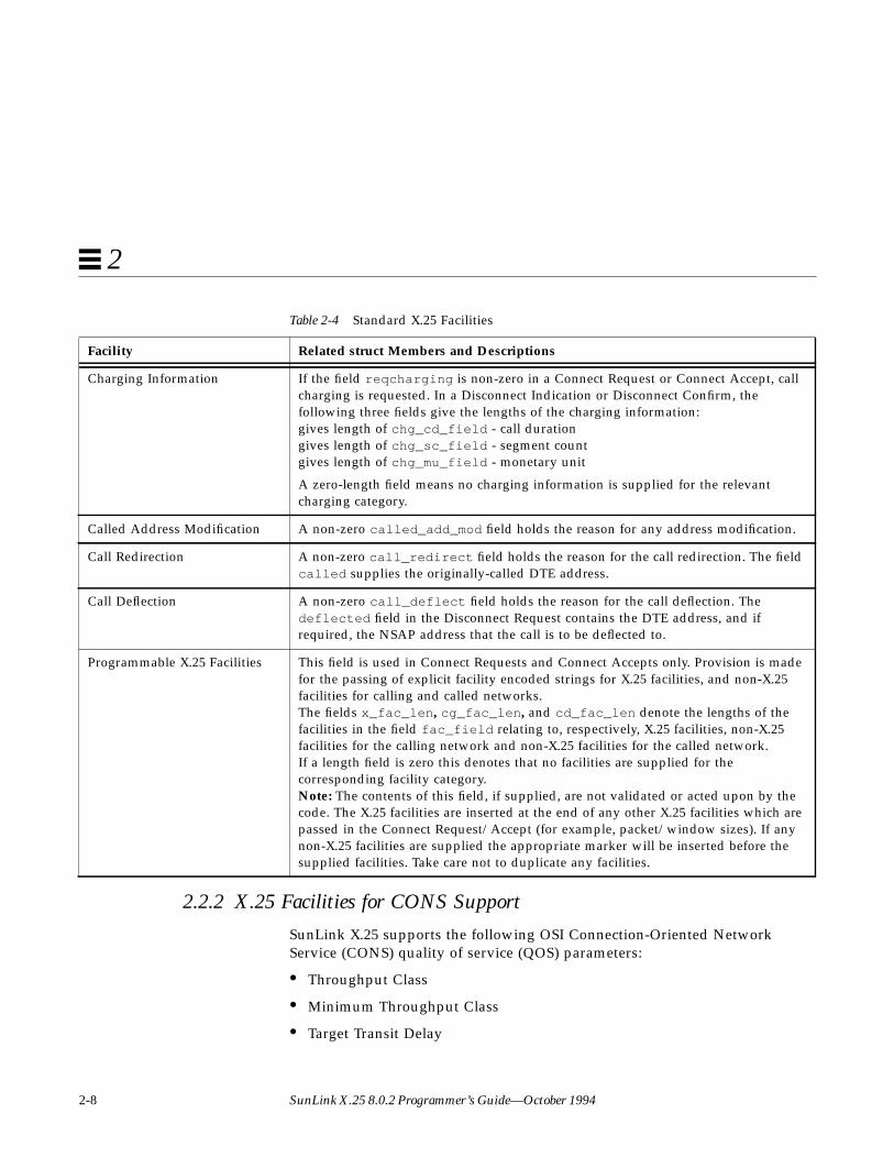
The fields in this structure are defined as follows:
Table 2-4 Standard X.25 Facilities
Facility Related struct Members and Descriptions
Fast Select For non-OSI applications like X.29, if the X.25 facility fast select is to be requested orindicated the field fastselreq is non-zero.
Fast Select with RestrictedResponse
In this case, the response is a Clear Request
Reverse Charging If reverse charging is requested or indicated for a connection, then the fieldreversecharges is non-zero.
Note: See the SunLink X.25 8.0.2 Reference Manual for instructions on enablingreceipt of reverse-charging.
Packet Concatenation, Packetand Window Size Negotiation
The pwoptions field is used to indicate per virtual-circuit options. The field is a bitmap with the following interpretation:bit 0:0 - Packet size negotiation NOT permitted.1 - Packet size negotiation permitted.bit 1:0 - Window size negotiation NOT permitted.1 - Window size negotiation permitted.bit 2:0 - No concatenation limit asserted.1 - Assert concatenation limit.
This is defined as follows:#define NEGOT_PKT 0x01 /* packet size is negotiable */#define NEGOT_WIN 0x02 /* window size is negotiable */#define ASSERT_HWM 0x04 /* assert concatenation limit */
This field is used for two reasons: 1) The X.25 software will always indicate thevalues of the window and packet sizes operating on the virtual circuit. However, thefield pwoptions for an incoming call indicates whether these values are negotiable.2) In Connect Requests and Connect Responses the NLI user can set a limit value,nsdulimit , for packet concatenation by the X.25 level that differs from the limit inthe subnetwork configuration database. It is not a negotiable option, so thatwhatever the user has requested is used.
Packet Size Negotiation If the fields locpacket and rempacket are non-zero, then they contain indicatedor negotiated encoded packet sizes, for the directions local-to-remote and remote-to-local, respectively.Note: actual packet size is 2 to the power of the value specified.#define DEF_X25_PKT 7 /* std default X.25 packet size */So, for example if the field locpacket is set to 7, the actual packet size will be 27 or128.

Data Structures 2-7
2
Window Size Negotiation If the fields locwsize and remwsize are non-zero, then they contain indicated ornegotiated window sizes, for the directions local-to-remote and remote-to-local,respectively.#define DEF_X25_WIN 2 /* std default X.25 window size */
Packet Concatenation If the field nsdulimit is non-zero, and the appropriate bit is set in the pwoptionsfield described above, then the nsdulimit specified is used as the concatenationlimit.
Network User Identification The Network User Identification (NUI) is used in Connect Requests and Responses.It is not available on X.25 (80) networks. If the field nui_len is non-zero, then theNetwork User Identification is supplied in nui_field of length nui_len octets.
RPOA Selection Recognized Private Operating Agency, used in Connect Requests only. If the fieldrpoa_len is non-zero, then the RPOA DNIC information is supplied inrpoa_field and is of length rpoa_len digits. The RPOA is stored in rpoa_field asBCD digits, with leading zeroes if necessary to right-justify the value. For example,the RPOA 198 would be stored as {0x01, 0x98}.
For an X.25 (80) network this is restricted to one RPOA of length 4 BCD digits. Thebasic format encoding is used for the RPOA selected.
For an X.25 (84) or X.25 (88) network one or more RPOAs may be selected. Theextended format encoding is used only if the number of RPOAs selected is greaterthan 1. The maximum number of RPOAs which may be selected is restricted to 4.Valid values for rpoa_len are 0, 4, 8, 12 and 16.
Closed User Groups This field is used in Connect Requests and Indications only. If the field cug_type isnon-zero, then the CUG information is supplied right-justified in cug_field . Forexample, the CUG 956 is stored as {0x09, 0x56}. Values for cug_type are:CUG — Closed User Group, up to 4 BCD digitsBCUG — Bilateral CUG (two members only), 4 BCD digits
Note: Incoming Closed User Group facilities are assumed to have been validated bythe network. No further checking is performed.
Table 2-4 Standard X.25 Facilities
Facility Related struct Members and Descriptions
2-8 SunLink X.25 8.0.2 Programmer’s Guide—October 1994
2
2.2.2 X.25 Facilities for CONS Support
SunLink X.25 supports the following OSI Connection-Oriented NetworkService (CONS) quality of service (QOS) parameters:
• Throughput Class
• Minimum Throughput Class
• Target Transit Delay
Charging Information If the field reqcharging is non-zero in a Connect Request or Connect Accept, callcharging is requested. In a Disconnect Indication or Disconnect Confirm, thefollowing three fields give the lengths of the charging information:gives length of chg_cd_field - call durationgives length of chg_sc_field - segment countgives length of chg_mu_field - monetary unit
A zero-length field means no charging information is supplied for the relevantcharging category.
Called Address Modification A non-zero called_add_mod field holds the reason for any address modification.
Call Redirection A non-zero call_redirect field holds the reason for the call redirection. The fieldcalled supplies the originally-called DTE address.
Call Deflection A non-zero call_deflect field holds the reason for the call deflection. Thedeflected field in the Disconnect Request contains the DTE address, and ifrequired, the NSAP address that the call is to be deflected to.
Programmable X.25 Facilities This field is used in Connect Requests and Connect Accepts only. Provision is madefor the passing of explicit facility encoded strings for X.25 facilities, and non-X.25facilities for calling and called networks.The fields x_fac_len , cg_fac_len , and cd_fac_len denote the lengths of thefacilities in the field fac_field relating to, respectively, X.25 facilities, non-X.25facilities for the calling network and non-X.25 facilities for the called network.If a length field is zero this denotes that no facilities are supplied for thecorresponding facility category.Note: The contents of this field, if supplied, are not validated or acted upon by thecode. The X.25 facilities are inserted at the end of any other X.25 facilities which arepassed in the Connect Request/Accept (for example, packet/window sizes). If anynon-X.25 facilities are supplied the appropriate marker will be inserted before thesupplied facilities. Take care not to duplicate any facilities.
Table 2-4 Standard X.25 Facilities
Facility Related struct Members and Descriptions

Data Structures 2-9
2
• Maximum Acceptable Transit Delay
• Use of Expedited Data
• Protection
• Priority
• Receipt Acknowledgement
CONS-related quality-of-service parameters are defined in the followingstructure:
#define MAX_PROT 32struct qosformat {
unsigned char reqtclass;unsigned char locthroughput, remthroughput;unsigned char reqminthruput;unsigned char locminthru, remminthru;unsigned char reqtransitdelay;unsigned short transitdelay;unsigned char reqmaxtransitdelay;unsigned short acceptable;unsigned char reqpriority;unsigned char reqprtygain;unsigned char reqprtykeep;unsigned char prtydata;unsigned char prtygain;unsigned char prtykeep;unsigned char reqlowprtydata;unsigned char reqlowprtygain;unsigned char reqlowprtykeep;unsigned char lowprtydata;unsigned char lowprtygain;unsigned char lowprtykeep;unsigned char protection_type;unsigned char prot_len;unsigned char lowprot_len;unsigned char protection[MAX_PROT];unsigned char lowprotection[MAX_PROT];unsigned char reqexpedited;unsigned char reqackservice;struct extraformat xtras;
};
2-10 SunLink X.25 8.0.2 Programmer’s Guide—October 1994
2
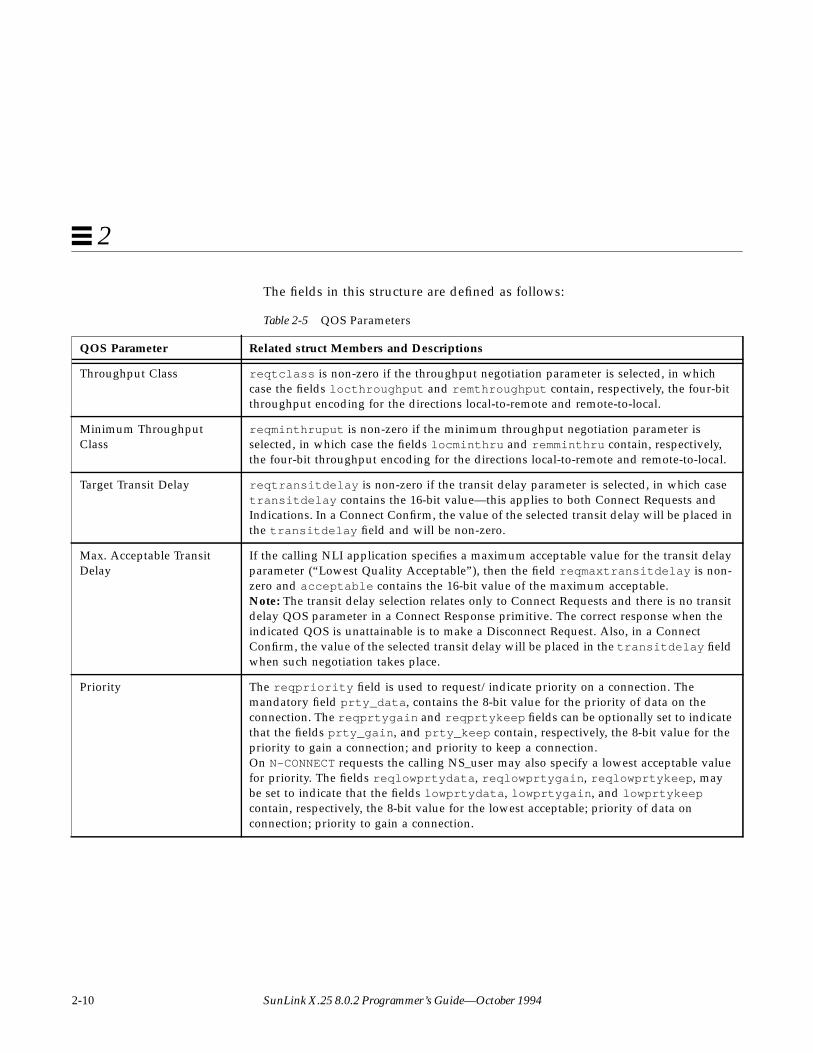
The fields in this structure are defined as follows:
Table 2-5 QOS Parameters
QOS Parameter Related struct Members and Descriptions
Throughput Class reqtclass is non-zero if the throughput negotiation parameter is selected, in whichcase the fields locthroughput and remthroughput contain, respectively, the four-bitthroughput encoding for the directions local-to-remote and remote-to-local.
Minimum ThroughputClass
reqminthruput is non-zero if the minimum throughput negotiation parameter isselected, in which case the fields locminthru and remminthru contain, respectively,the four-bit throughput encoding for the directions local-to-remote and remote-to-local.
Target Transit Delay reqtransitdelay is non-zero if the transit delay parameter is selected, in which casetransitdelay contains the 16-bit value—this applies to both Connect Requests andIndications. In a Connect Confirm, the value of the selected transit delay will be placed inthe transitdelay field and will be non-zero.
Max. Acceptable TransitDelay
If the calling NLI application specifies a maximum acceptable value for the transit delayparameter (“Lowest Quality Acceptable”), then the field reqmaxtransitdelay is non-zero and acceptable contains the 16-bit value of the maximum acceptable.Note: The transit delay selection relates only to Connect Requests and there is no transitdelay QOS parameter in a Connect Response primitive. The correct response when theindicated QOS is unattainable is to make a Disconnect Request. Also, in a ConnectConfirm, the value of the selected transit delay will be placed in the transitdelay fieldwhen such negotiation takes place.
Priority The reqpriority field is used to request/indicate priority on a connection. Themandatory field prty_data , contains the 8-bit value for the priority of data on theconnection. The reqprtygain and reqprtykeep fields can be optionally set to indicatethat the fields prty_gain , and prty_keep contain, respectively, the 8-bit value for thepriority to gain a connection; and priority to keep a connection.On N-CONNECT requests the calling NS_user may also specify a lowest acceptable valuefor priority. The fields reqlowprtydata , reqlowprtygain , reqlowprtykeep , maybe set to indicate that the fields lowprtydata , lowprtygain , and lowprtykeepcontain, respectively, the 8-bit value for the lowest acceptable; priority of data onconnection; priority to gain a connection.
Data Structures 2-11
2
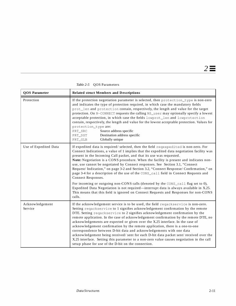
Protection If the protection negotiation parameter is selected, then protection_type is non-zeroand indicates the type of protection required, in which case the mandatory fieldsprot_len and protection contain, respectively, the length and value for the targetprotection. On N-CONNECT requests the calling NS_user may optionally specify a lowestacceptable protection, in which case the fields lowprot_len and lowprotectioncontain, respectively, the length and value for the lowest acceptable protection. Values forprotection_type are:PRT_SRC Source address specificPRT_DST Destination address specificPRT_GLB Globally unique
Use of Expedited Data If expedited data is required/selected, then the field reqexpedited is non-zero. ForConnect Indications, a value of 1 implies that the expedited data negotiation facility waspresent in the Incoming Call packet, and that its use was requested.Note: Negotiation is a CONS procedure. When the facility is present and indicates non-use, use cannot be negotiated by Connect responses. See Section 3.1, “ConnectRequest/Indication,” on page 3-2 and Section 3.2, “Connect Response/Confirmation,” onpage 3-4 for a description of the use of the CONS_call field in Connect Requests andConnect Responses.
For incoming or outgoing non-CONS calls (denoted by the CONS_call flag set to 0),Expedited Data Negotiation is not required—interrupt data is always available in X.25.This means that this field is ignored on Connect Requests and Responses for non-CONScalls.
AcknowledgementService
If the acknowledgement service is to be used, the field reqackservice is non-zero.Setting reqackservice to 1 signifies acknowledgement confirmation by the remoteDTE. Setting reqackservice to 2 signifies acknowledgement confirmation by theremote application. In the case of acknowledgement confirmation by the remote DTE, noacknowledgements are expected or given over the X.25 interface. In the case ofacknowledgement confirmation by the remote application, there is a one-to-onecorrespondence between D-bit data and acknowledgements with one dataacknowledgement being received/sent for each D-bit data packet sent/received over theX.25 interface. Setting this parameter to a non-zero value causes negotiation in the callsetup phase for use of the D-bit on the connection.
Table 2-5 QOS Parameters
QOS Parameter Related struct Members and Descriptions

2-12 SunLink X.25 8.0.2 Programmer’s Guide—October 1994
2
3-1
NLI Message Primitives 3
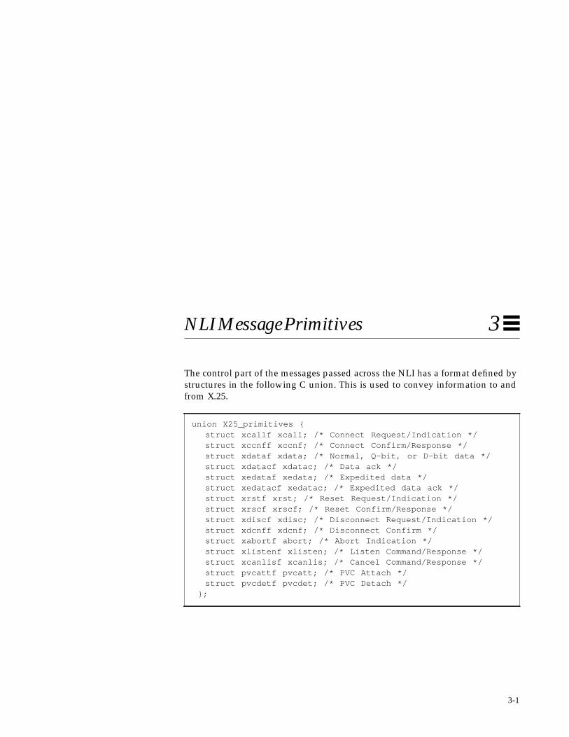
The control part of the messages passed across the NLI has a format defined bystructures in the following C union. This is used to convey information to andfrom X.25.
union X25_primitives {struct xcallf xcall; /* Connect Request/Indication */struct xccnff xccnf; /* Connect Confirm/Response */struct xdataf xdata; /* Normal, Q-bit, or D-bit data */struct xdatacf xdatac; /* Data ack */struct xedataf xedata; /* Expedited data */struct xedatacf xedatac; /* Expedited data ack */struct xrstf xrst; /* Reset Request/Indication */struct xrscf xrscf; /* Reset Confirm/Response */struct xdiscf xdisc; /* Disconnect Request/Indication */struct xdcnff xdcnf; /* Disconnect Confirm */struct xabortf abort; /* Abort Indication */struct xlistenf xlisten; /* Listen Command/Response */struct xcanlisf xcanlis; /* Cancel Command/Response */struct pvcattf pvcatt; /* PVC Attach */struct pvcdetf pvcdet; /* PVC Detach */
};

3-2 SunLink X.25 8.0.2 Programmer’s Guide—October 1994
3
The above messages have common fields which can be accessed by thefollowing type:
The messages to and from the application are classified into control and data,depending on the value of xl_type which is either XL_CTL (control) orXL_DAT (data). Within each classification, the exact message identity isdetermined by the xl_command qualifier, and it is important to ensure that thecombination of xl_type and xl_command is consistent. Each of these cases isdescribed in the following subsections.
Note – Some of the examples in this chapter mention CONS calls. These areonly relevant to OSI-type applicatations.
3.1 Connect Request/IndicationThe control part of a Connect Request or Indication message has a formatdefined in the following structure:
typedef struct xhdrf {unsigned char xl_type; /* XL_CTL/XL_DAT */unsigned char xl_command; /* Command */
} S_X25_HDR;
struct xcallf {unsigned char xl_type; /* Always XL_CTL */unsigned char xl_command; /* Always N_CI */int conn_id; /*connection id returned in Connect Response or
Disconnect */unsigned char CONS_call; /* When set, indicates a CONS call
*/unsigned char negotiate_qos; /* When set, negotiate
facilities *//* etc. or else use defaults */
struct xaddrf calledaddr; /* The called and */struct xaddrf callingaddr; /* calling addresses */struct qosformat qos; /* Facilities and CONS qos: if
negotiate_qos is set */};

NLI Message Primitives 3-3
3
This structure is used when calls are requested or indicated across the X.25interface. The data part of the message contains the call user data (if any).Other components are listed as follows.
For information on X.25 facilities, refer to Section 2.2, “Quality of Service andX.25 Facilities,” on page 2-4.
Table 3-1 Connect Request/Indication Message
Member Description
conn_id For incoming calls, an attempt is made to match the called address and call user data with that ofone of the listening applications. If a match is found, then the indication is passed to thatapplication with a conn_id identifier, which must be returned in the Connect Response orDisconnect Request to accept or reject the connection. Leave this value as 0.
CONS_call For requests, this field, when set, indicates that CONS procedures should be used for the call.
negotiate_qos A non-zero value shows that facilities and quality of service (QOS) are being negotiated. A zerovalue means the initiator is requesting all default values.
calledaddr Holds the called address.
callingaddr Holds the calling address.
qos Holds the facilities requested/indicated. See Section 5.1, “Opening a Connection,” on page 5-2 formore information on QOS negotiation.
3-4 SunLink X.25 8.0.2 Programmer’s Guide—October 1994
3
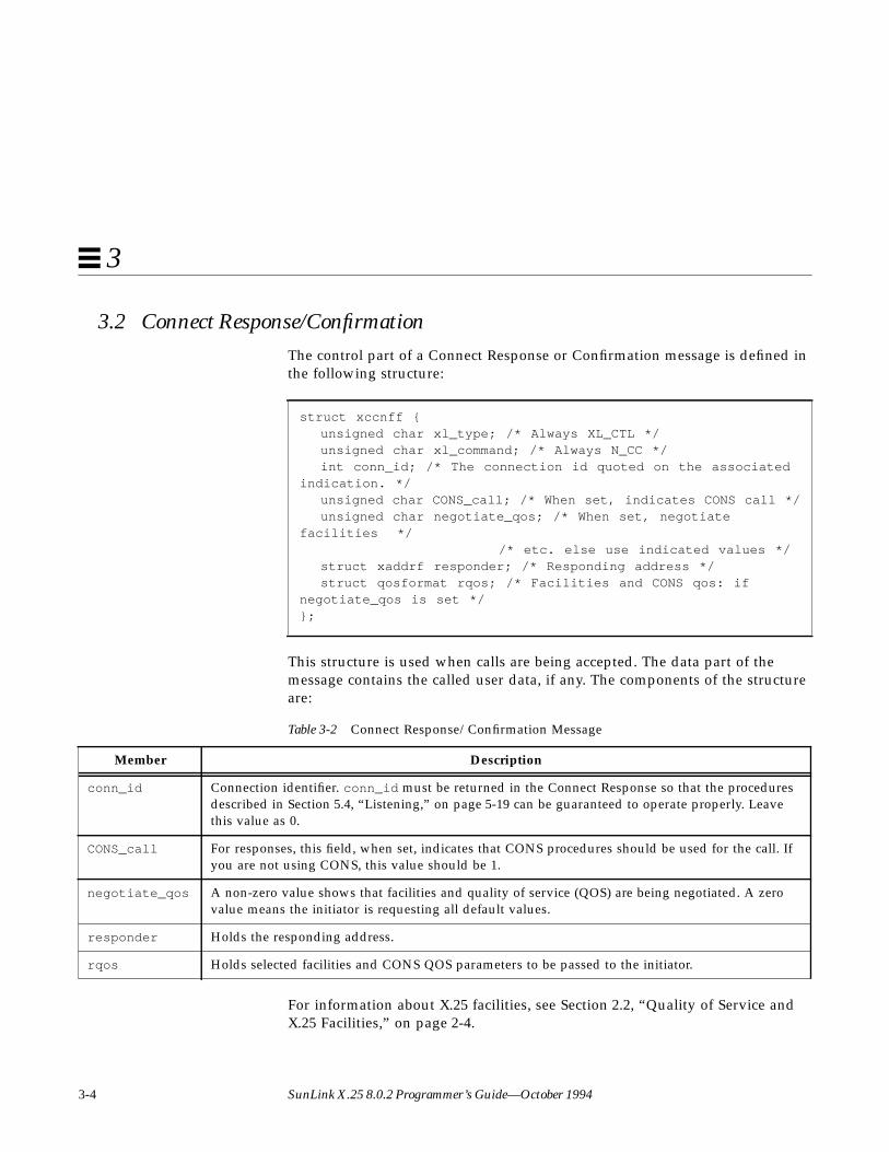
3.2 Connect Response/ConfirmationThe control part of a Connect Response or Confirmation message is defined inthe following structure:
This structure is used when calls are being accepted. The data part of themessage contains the called user data, if any. The components of the structureare:
For information about X.25 facilities, see Section 2.2, “Quality of Service andX.25 Facilities,” on page 2-4.
struct xccnff {unsigned char xl_type; /* Always XL_CTL */unsigned char xl_command; /* Always N_CC */int conn_id; /* The connection id quoted on the associated
indication. */unsigned char CONS_call; /* When set, indicates CONS call */unsigned char negotiate_qos; /* When set, negotiate
facilities *//* etc. else use indicated values */
struct xaddrf responder; /* Responding address */struct qosformat rqos; /* Facilities and CONS qos: if
negotiate_qos is set */};
Table 3-2 Connect Response/Confirmation Message
Member Description
conn_id Connection identifier. conn_id must be returned in the Connect Response so that the proceduresdescribed in Section 5.4, “Listening,” on page 5-19 can be guaranteed to operate properly. Leavethis value as 0.
CONS_call For responses, this field, when set, indicates that CONS procedures should be used for the call. Ifyou are not using CONS, this value should be 1.
negotiate_qos A non-zero value shows that facilities and quality of service (QOS) are being negotiated. A zerovalue means the initiator is requesting all default values.
responder Holds the responding address.
rqos Holds selected facilities and CONS QOS parameters to be passed to the initiator.

NLI Message Primitives 3-5
3
3.3 DataThe control part of a data message is defined in the following structure:
This structure is used when data crosses the X.25 interface. Its components areas follows.
The data part of the data message contains the user data.
Note – No acknowledgement for this data is given to, or expected from, theapplication unless the D-bit is set and Application-to-Application ReceiptConfirmation is being used.
3.4 Data Acknowledgement Request/IndicationThis following structure is associated with this message:
struct xdataf {unsigned char xl_type; /* Always XL_DAT */unsigned char xl_command; /* Always N_Data */unsigned char More; /* Set when more data is required
to complete the nsdu */unsigned char setDbit, /* Set when data carries X.25D-bit */unsigned char setQbit; /* Set when data carries X.25 Q-bit */
};
Table 3-3 Data Message
Member Description
More Shows whether there is more of this network service data unit to be received/sent.
setQbit Used to request or indicate that the Q-bit is set when user data is transmitted/received.
setDbit Used to request or indicate that the D-bit is set when user data is transmitted/received.
struct xdatacf {unsigned char xl_type; /* Always XL_DAT */unsigned char xl_command; /* Always N_DAck */
};

3-6 SunLink X.25 8.0.2 Programmer’s Guide—October 1994
3
This structure is used when a Data Acknowledgement Request or a DataAcknowledgement Indication crosses the X.25 interface.
When receipt confirmation from the remote application is active on a virtualcircuit, this structure is used to acknowledge a previous DataAcknowledgement Request or Indication which had the D-bit set. There is aone-to-one correspondence between D-bit data and acknowledgements, withone Data Acknowledgement being received/sent for each D-bit data packetsent/received. It is always the oldest outstanding D-bit packet that is beingacknowledged.
For CONS calls, if receipt acknowledgement has been negotiated on theconnection, then the above procedures should apply for any D-bit data sent orreceived.
For non-CONS calls, only if the reqackservice field in the qos structure hasbeen set to the appropriate value will the above procedures apply for any D-bitdata sent or received. Otherwise, no acknowledgement is expected or given.
3.5 Expedited DataThe control part of an expedited data message has a format defined in thefollowing structure:
This structure is used when expedited data, carried by an X.25 Interruptpacket, crosses the X.25 interface. No parameters are required.
The data part of the message contains the user data. The expedited data is aconfirmed primitive and must be acknowledged (see below) before anotherexpedited data unit can be requested or indicated.
struct xedataf {unsigned char xl_type; /* Always XL_DAT */unsigned char xl_command; /* Always N_EData */
};

NLI Message Primitives 3-7
3
3.6 Expedited Data AcknowledgementThe control part of the expedited data acknowledgement message has a formatdefined in the following structure:
This structure is used when expedited data needs to be, or is being,acknowledged. No parameters or user data are required.
3.7 Reset Request/IndicationThe control part of a Reset Request or an Indication message has a formatdefined in the following structure:
This structure is used when a Reset Request/Indication crosses the X.25interface. Data is never associated with the primitive.
The X.25 cause and diagnostic bytes, cause and diag , are presented as well asthe CONS originator and reason codes that are mapped from these.
For a Reset Request on a non-CONS call, the user can specify a non-zero causecode. This has no effect for a CONS call; the value is set to zero by the system.
A Reset Request is a confirmed primitive and must be acknowledged beforeanother Reset Request can be requested.
struct xedatacf {unsigned char xl_type; /* Always XL_DAT */unsigned char xl_command; /* Always N_EAck */
};
struct xrstf {unsigned char xl_type; /* Always XL_CTL */unsigned char xl_command; /* Always N_RI */unsigned char originator, /* Originator and Reason mapped */
reason, /* from X.25 cause/diag in indications */cause, /* X.25 cause byte */diag; /* X.25 diagnostic byte */
};

3-8 SunLink X.25 8.0.2 Programmer’s Guide—October 1994
3
Note – A Reset primitive is an acknowledged service (see the associatedstructure xrscf ). A collision between a Reset Indication and a Reset Requestis taken to acknowledge the Reset—no Reset Confirmation is then requiredbefore another Reset Request can be sent. Normally, Resets are handled by theappliation.
3.8 Reset Response/ConfirmThe control part of a Reset Response or Confirm message has a format definedin the following structure:
This structure is used when a Reset Confirm or Response to a previous Resetcrosses the X.25 interface. There are no parameters or data associated with theprimitive. The comments above on reset collision also apply here.
struct xrscf {unsigned char xl_type; /* Always XL_CTL */unsigned char xl_command; /* Always N_RC */
};

NLI Message Primitives 3-9
3
3.9 Disconnect Request/IndicationThe control part of a Disconnect Request or Indication message has a formatdefined in the following structure:
This structure is used when a Disconnect Request/Indication crosses the X.25interface. The data part of the message contains the Clear User Data, if any.
The X.25 cause and diagnostic bytes, cause and diag , are presented, as wellas the CONS originator and reason codes mapped from these. For a DisconnectRequest on a non-CONS call, the user can specify a non-zero cause code. Thishas no effect for a CONS call; the value is set to zero by the system. Otherparameters are listed below.
struct xdiscf {unsigned char xl_type; /* Always XL_CTL */unsigned char xl_command; /* Always N_DI */unsigned char originator, /* Originator and Reason mapped
from */reason, /* X.25 cause/diag in indications */cause, /* X.25 cause byte */diag; /* X.25 diagnostic byte */
int conn_id; /* The connection id (for reject only) */unsigned char indicated_qos; /* When set, facilities
indicated */struct xaddrf responder; /* CONS responder address */struct xaddrf deflected; /* Deflected address */struct qosformat qos; /* If indicated_qos is set, holds
facilities and CONS qos */};
Table 3-4 Disconnect Request/Indication Parameters
Member Description
indicated_qos Non-zero value shows that facilities and QOS are being indicated.
responder Contains the responding address.
deflected Used in conjunction with the call_deflect facility in the qos structure, to convey the addressof the remote DTE that the call is to be deflected to.
3-10 SunLink X.25 8.0.2 Programmer’s Guide—October 1994
3
The Disconnect Request from an application is confirmed unless it is a rejectionof a previous Connect Indication. When it is not a rejection, the X.25 driversends a Disconnect Confirm to the application when the Clear Confirmation isreceived. This guarantees that, once the Disconnect Confirm is observed by theapplication, no more messages are sent on this stream. For this reason, afterrequesting disconnection, the application should read and discard all messagesfrom the stream until the Disconnect Confirm is received.
For call rejection, no “acknowledgement” is sent. However, the applicationmust supply the connection identifier presented in the Connect Indication sothat the appropriate circuit is cleared. In the case of a Disconnect Indication, allmessages sent downstream except connect messages are discarded silently.
Note – A disconnect collision can occur. If it does, the “acknowledgement” canbe taken to be complete.
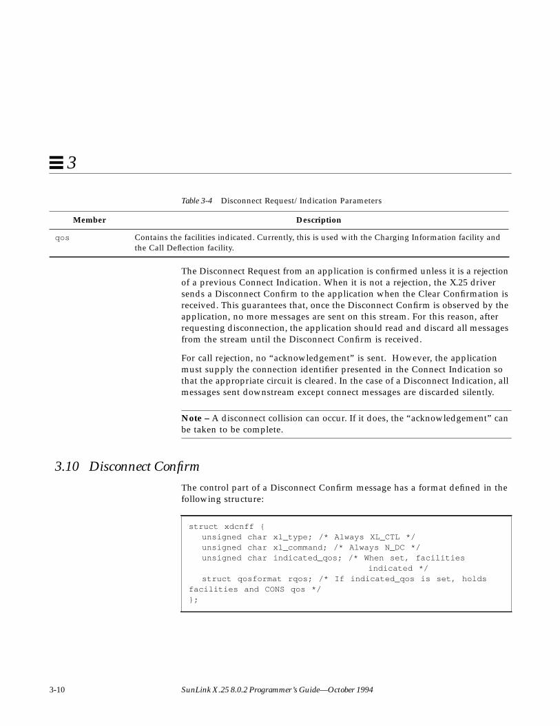
3.10 Disconnect ConfirmThe control part of a Disconnect Confirm message has a format defined in thefollowing structure:
qos Contains the facilities indicated. Currently, this is used with the Charging Information facility andthe Call Deflection facility.
struct xdcnff {unsigned char xl_type; /* Always XL_CTL */unsigned char xl_command; /* Always N_DC */unsigned char indicated_qos; /* When set, facilities indicated */struct qosformat rqos; /* If indicated_qos is set, holds
facilities and CONS qos */};
Table 3-4 Disconnect Request/Indication Parameters
Member Description
NLI Message Primitives 3-11
3
This stucture is used when a Disconnect Confirm crosses the X.25 interface.There is no data associated with this primitive. The components of thestructure are:
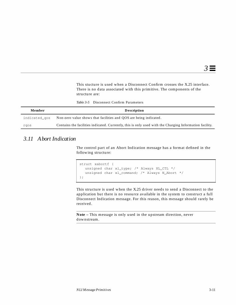
3.11 Abort IndicationThe control part of an Abort Indication message has a format defined in thefollowing structure:
This structure is used when the X.25 driver needs to send a Disconnect to theapplication but there is no resource available in the system to construct a fullDisconnect Indication message. For this reason, this message should rarely bereceived.
Note – This message is only used in the upstream direction, neverdownstream.
Table 3-5 Disconnect Confirm Parameters
Member Description
indicated_qos Non-zero value shows that facilities and QOS are being indicated.
rqos Contains the facilities indicated. Currently, this is only used with the Charging Information facility.
struct xabortf {unsigned char xl_type; /* Always XL_CTL */unsigned char xl_command; /* Always N_Abort */
};

3-12 SunLink X.25 8.0.2 Programmer’s Guide—October 1994
3
3.12 Listen Command/ResponseThe control part of a Listen Command or Response message has a formatdefined in the following structure:
This structure is used when an NLI application wants to register interest inincoming calls. The components are listed below.
For more information, refer to Chapter 4, “Listens.”
struct xlistenf {unsigned char xl_type; /* Always XL_CTL */unsigned char xl_command; /* Always N_Xlisten */int lmax; /* Maximum number of CI’s at a time */int l_result; /* Result flag */
};
Table 3-6 Listen Command/Response Parameters
Member Description
lmax Maximum number of Connect Indications that the listener is willing to handle at one time. The datapart of the message carries the address(es) in which the listener is interested (refer also to Chapter 4,“Listens”).
Note: listen requests are cumulative but the lmax value (number of simultaneously handledConnect Indications) is not. This means that several listen requests can be made on a single stream,in which case the lmax value contained in the last listen message specifies the number ofsimultaneously handled Connect Indications.
l_result The result of the listen request is acknowledged upstream with the same message. An error in theparameters or a lack of resources to set up the listen causes this flag to be set to a non-zero value.
NLI Message Primitives 3-13
3
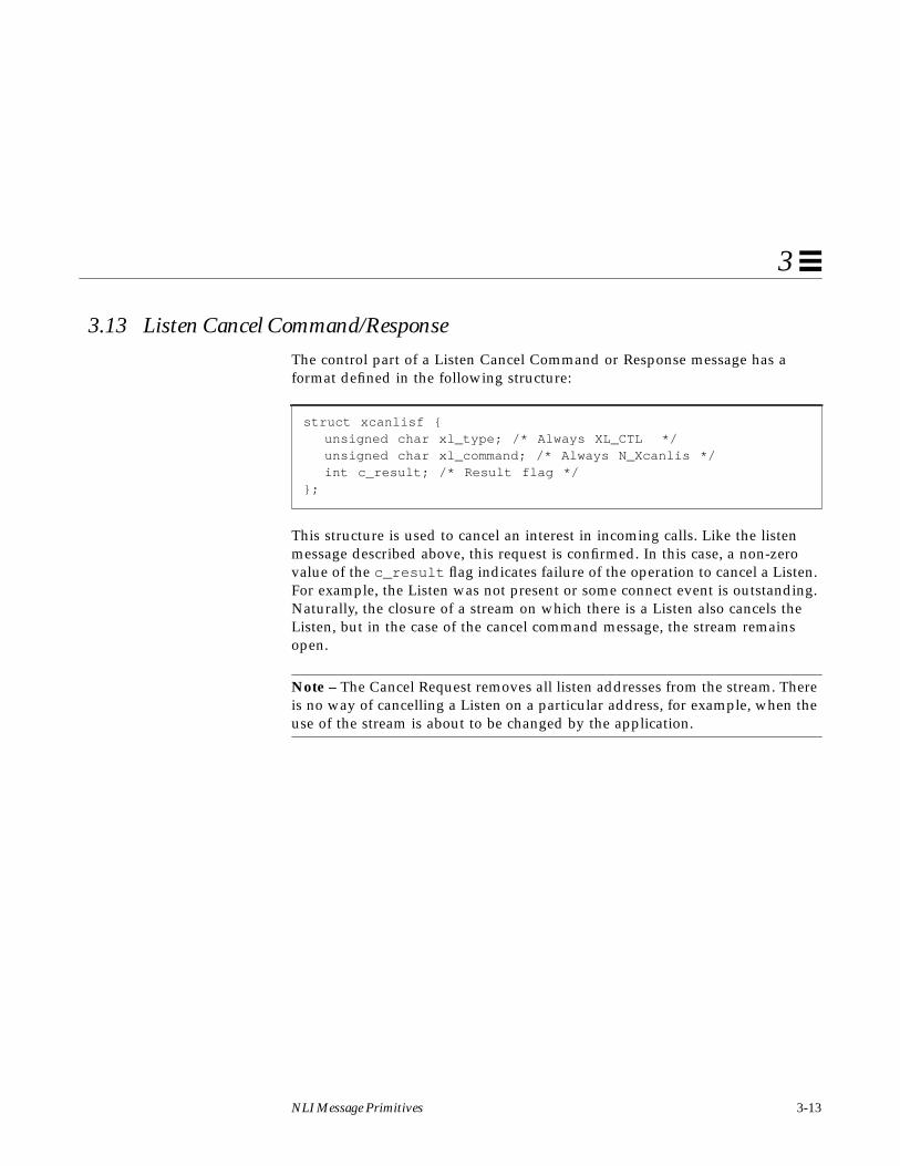
3.13 Listen Cancel Command/ResponseThe control part of a Listen Cancel Command or Response message has aformat defined in the following structure:
This structure is used to cancel an interest in incoming calls. Like the listenmessage described above, this request is confirmed. In this case, a non-zerovalue of the c_result flag indicates failure of the operation to cancel a Listen.For example, the Listen was not present or some connect event is outstanding.Naturally, the closure of a stream on which there is a Listen also cancels theListen, but in the case of the cancel command message, the stream remainsopen.
Note – The Cancel Request removes all listen addresses from the stream. Thereis no way of cancelling a Listen on a particular address, for example, when theuse of the stream is about to be changed by the application.
struct xcanlisf {unsigned char xl_type; /* Always XL_CTL */unsigned char xl_command; /* Always N_Xcanlis */int c_result; /* Result flag */
};
3-14 SunLink X.25 8.0.2 Programmer’s Guide—October 1994
3
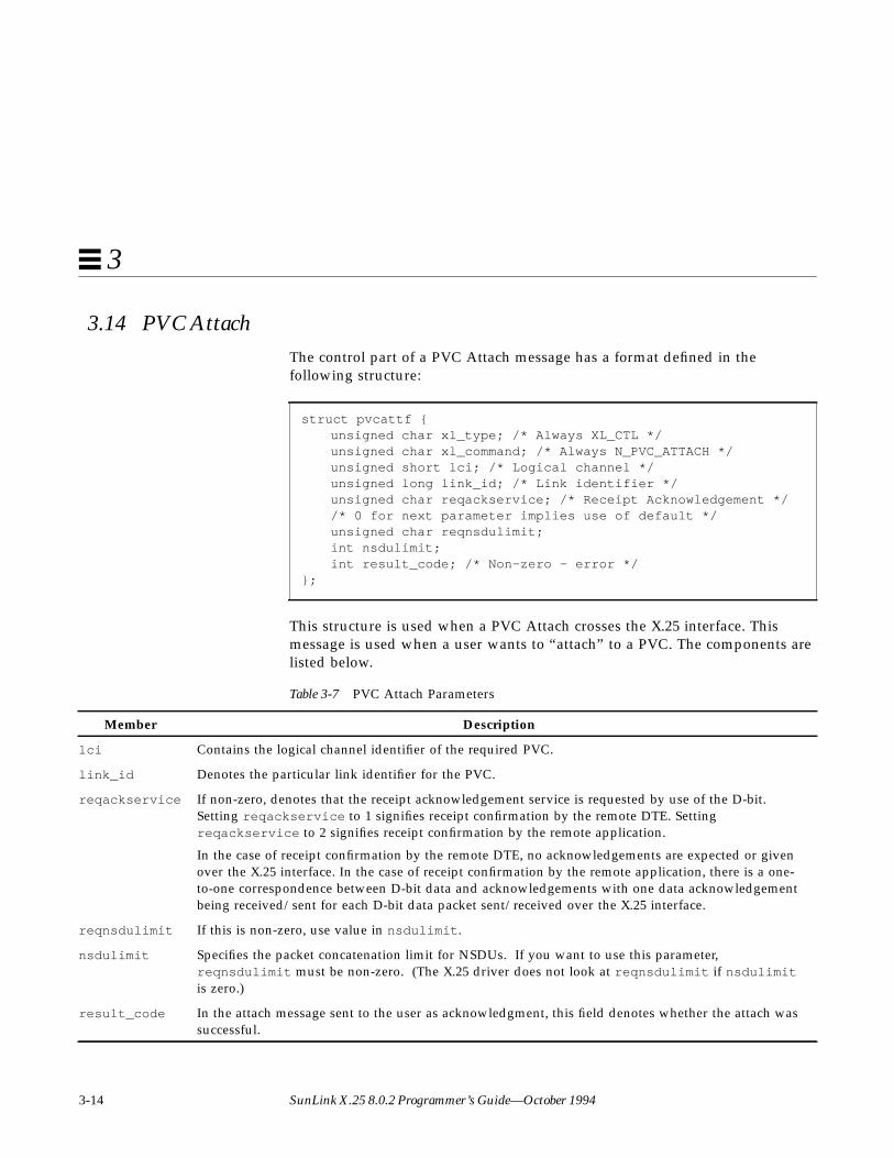
3.14 PVC AttachThe control part of a PVC Attach message has a format defined in thefollowing structure:
This structure is used when a PVC Attach crosses the X.25 interface. Thismessage is used when a user wants to “attach” to a PVC. The components arelisted below.
struct pvcattf {unsigned char xl_type; /* Always XL_CTL */unsigned char xl_command; /* Always N_PVC_ATTACH */unsigned short lci; /* Logical channel */unsigned long link_id; /* Link identifier */unsigned char reqackservice; /* Receipt Acknowledgement *//* 0 for next parameter implies use of default */unsigned char reqnsdulimit;int nsdulimit;int result_code; /* Non-zero - error */
};
Table 3-7 PVC Attach Parameters
Member Description
lci Contains the logical channel identifier of the required PVC.
link_id Denotes the particular link identifier for the PVC.
reqackservice If non-zero, denotes that the receipt acknowledgement service is requested by use of the D-bit.Setting reqackservice to 1 signifies receipt confirmation by the remote DTE. Settingreqackservice to 2 signifies receipt confirmation by the remote application.
In the case of receipt confirmation by the remote DTE, no acknowledgements are expected or givenover the X.25 interface. In the case of receipt confirmation by the remote application, there is a one-to-one correspondence between D-bit data and acknowledgements with one data acknowledgementbeing received/sent for each D-bit data packet sent/received over the X.25 interface.
reqnsdulimit If this is non-zero, use value in nsdulimit .
nsdulimit Specifies the packet concatenation limit for NSDUs. If you want to use this parameter,reqnsdulimit must be non-zero. (The X.25 driver does not look at reqnsdulimit if nsdulimitis zero.)
result_code In the attach message sent to the user as acknowledgment, this field denotes whether the attach wassuccessful.

NLI Message Primitives 3-15
3
3.15 PVC DetachThe control part of a PVC Detach message has a format defined in thefollowing structure:
This structure is used when a PVC Detach crosses the X.25 interface. Thismessage is used when a user wants to "detach" from the PVC. This allows theuse of the stream to be changed.
The Detach message is acknowledged to the user by returning a Detachmessage, in which the field reason_code denotes whether the Detach wassuccessful.
This message is also used by the X.25 driver to inform the user of some failureof the PVC. These include link down, remote end not responding, and so on.When the message is sent by the X.25 driver, the field reason_code gives thereason for the Detach.
struct pvcdetf {unsigned char xl_type; /* Always XL_CTL */unsigned char xl_command; /* Always N_PVC_DETACH */int reason_code; /* Reports why */
};

3-16 SunLink X.25 8.0.2 Programmer’s Guide—October 1994
3

4-1
Listens 4
The major features of listening are:
• Any number of processes can listen simultaneously, subject to resourceconstraints imposed by the system administrator. Moreover, any number ofthese processes can listen at the same (set of) called addresses. Note that thereis no means of listening for a particular calling address.
• An application can elect to listen and handle one or more ConnectIndications at a time. The most likely use of this feature is when theapplication wants to make use of the following facility:
• An incoming connection may be accepted on a stream other than the onewhich received the Connect Indication (the listening stream).
• An application built on the NLI streams interface can listen on multipleaddresses. This results in a more efficient use of kernel resources than if theapplication had to open a separate stream to listen on each address.
4.1 Listening for Incoming CallsWhen an application wishes to listen for incoming calls, it must specify the(called) address(es) and Call User Data (CUD) field values for which it isprepared to accept calls. These addresses and values are passed as part of alisten request.

4-2 SunLink X.25 8.0.2 Programmer’s Guide—October 1994
4
The control part of the message is accompanied by a data part containing theaddresses to be registered for incoming calls. The data portion is treated as abyte stream of CUD and addresses conforming to the following definition:
It is important to note that, depending on both the value of the “mode” bytesand the lengths, not all fields need be present. Refer to the individual fielddescriptions below for more details.
4.2 Call User Data MatchingThe fields l_cumode , l_culength and l_cubytes are used to match theCUD field of the incoming call, if any, against that specified in the Listenrequest.
unsigned char l_cumode;unsigned char l_culength;unsigned char l_cubytes [l_culength];unsigned char l_mode;unsigned char l_type;unsigned char l_length;unsigned char l_add[(l_length+1)>>1];
Table 4-1 Variables for CUD Matching
Variable Name Description
l_cumode Defines the type of matching. Three cases are possible:
X25_DONTCARE
The listener ignores the CUD; l_culength and l_cubytes are omitted.
X25_IDENTITY
The listener match is only made if all bytes of the CUD field are the same as the suppliedl_cubytes .
X25_STARTSWITH
The listener match is only made if the leading bytes of the CUD Field are the same as thesupplied l_cubytes .
The last two are intended to distinguish, for example, X.29, from other higher level protocols.

Listens 4-3
4
4.3 Address MatchingThe fields l_mode , l_type , l_length and l_add are used to match theaddress field(s) of the incoming call against that specified in the Listen request.
l_culength Length of the CUD in octets for an X25_IDENTITY or X25_STARTSWITH CUD Field match. Ifl_culength is zero, the l_cubytes are omitted. Currently, the range for l_culength is zero to16 inclusive. The application still has to check the full CUD Field.
l_cubytes String of bytes sought in the call user data field when l_cumode is X25_IDENTITY orX25_STARTSWITH.
Table 4-2 Variables for Address Matching
Variable Name Description
l_mode Defines the type of matching:
X25_DONTCARE
The listener ignores the address; l_type, l_length , and l_add are omitted.
X25_IDENTITY
The listener match is only made if all digits of the address are the same as the suppliedl_add .
X25_STARTSWITH
The listener match is only made if the leading digits of the address are the same as thesupplied l_add .
X25_PATTERN
The listener match is made on partial addresses, allowing the use of wildcard digits.
The last two are intended to distinguish, for example, X.29, from other higher level protocols.
l_type The type of the address entry; l_type can have two values, X25_DTE or X25_NSAP. It denotes theimportant addressing quantity. For X.25 (84) and X.25 (88), for example, NSAP addresses (orextended addresses) are the important addresses, while for X.25 (80), where there is no NSAPaddress, the DTE address is the important quantity. Various applications can be distinguished byX.25 DTE subaddress where necessary.
On many X.25 (84) and X.25 (88) networks, it is possible to listen on either X25_DTE or X25_NSAPaddresses. This is not possible when running X.25 (84) or X.25 (88) over LLC2 on the LAN. In thiscase, the DTE address field is NULL and the X25_NSAP field is used.
Table 4-1 Variables for CUD Matching
Variable Name Description
4-4 SunLink X.25 8.0.2 Programmer’s Guide—October 1994
4
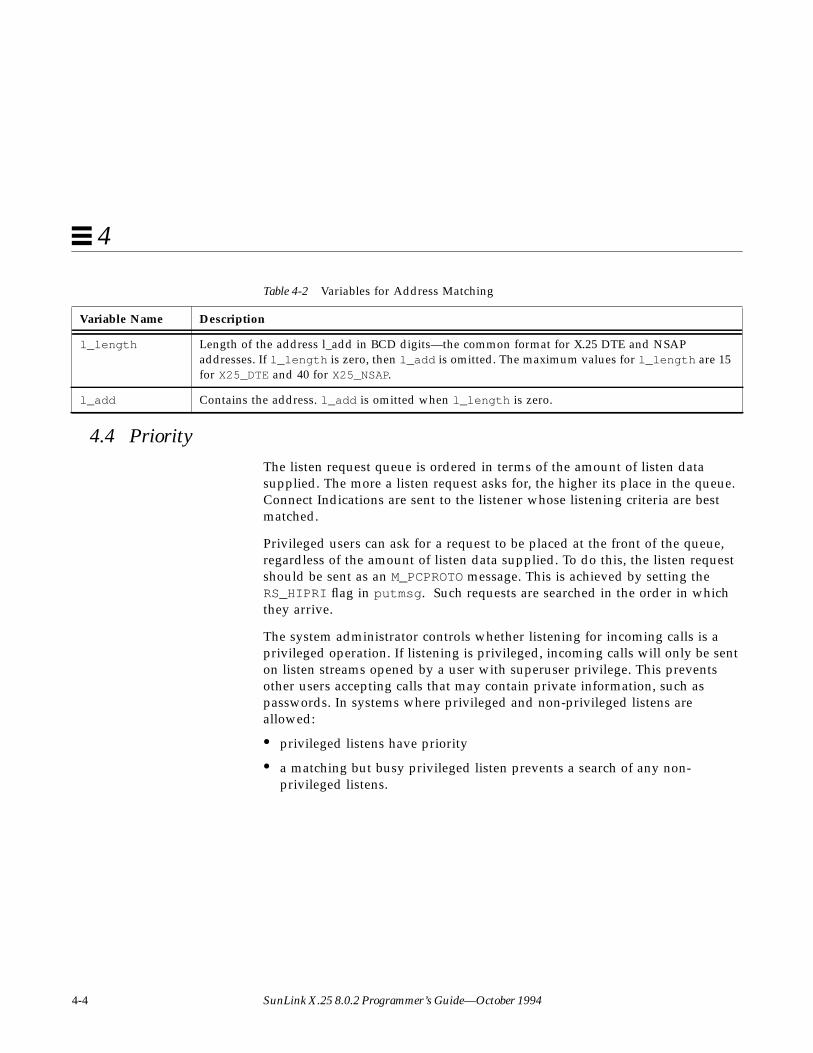
4.4 PriorityThe listen request queue is ordered in terms of the amount of listen datasupplied. The more a listen request asks for, the higher its place in the queue.Connect Indications are sent to the listener whose listening criteria are bestmatched.
Privileged users can ask for a request to be placed at the front of the queue,regardless of the amount of listen data supplied. To do this, the listen requestshould be sent as an M_PCPROTO message. This is achieved by setting theRS_HIPRI flag in putmsg . Such requests are searched in the order in whichthey arrive.
The system administrator controls whether listening for incoming calls is aprivileged operation. If listening is privileged, incoming calls will only be senton listen streams opened by a user with superuser privilege. This preventsother users accepting calls that may contain private information, such aspasswords. In systems where privileged and non-privileged listens areallowed:
• privileged listens have priority
• a matching but busy privileged listen prevents a search of any non-privileged listens.
l_length Length of the address l_add in BCD digits—the common format for X.25 DTE and NSAPaddresses. If l_length is zero, then l_add is omitted. The maximum values for l_length are 15for X25_DTE and 40 for X25_NSAP.
l_add Contains the address. l_add is omitted when l_length is zero.
Table 4-2 Variables for Address Matching
Variable Name Description

5-1
Streams Programming Examples 5
Note – See sample programs that use the NLI in:/opt/SUNWconn/x25/samples.nli .
To perform any of the operations described in this section, the application mustopen a stream to the X.25 PLP Driver. Once the stream has been opened it canbe used for initiating, listening for, or accepting a connection. There is a one-to-one mapping between X.25 virtual circuits and PLP driver streams. Once aconnection has been established on a stream, the stream cannot be used otherthan for passing data and protocol messages for that connection. Such a streamis opened on the /dev/x25 major device as follows:
if ((x25_fd = open("/dev/x25", O_RDWR)) < 0) {perror("Opening Stream");exit(1);}

5-2 SunLink X.25 8.0.2 Programmer’s Guide—October 1994
5
5.1 Opening a ConnectionTo establish a connection on an open stream, an application must do thefollowing:
1. Allocate a Connect Request structure.
2. Supply the Connect Request with the quality of service and facilitiesparameters.
3. Set the called (and optionally calling) addresses.
4. Pass the Connect Request down to the X.25 Driver.
5. Wait for the connect confirmation or rejection.
The following sections describe the procedures for opening a connection for astandard X.25 call and for a Connection-Oriented Network Service (CONS) callthat uses X.25, respectively.

Streams Programming Examples 5-3
5
5.1.1 Standard X.25 Calls
The following example opens a connection for a non-CONS call:
Note – When negotiate_qos is true (non-zero), setting the QOS fields to zeromeans that the connection uses defaults for QOS and Facilities. If required,these can be set to different values (see Section 2.2, “Quality of Service andX.25 Facilities,” on page 2-4 and Section 3.1, “Connect Request/Indication,” onpage 3-2 for more details), but it is recommended that the entire QOS structurebe zeroed first, as shown. This is preferable to setting each field individually, asit allows for any future additions to this structure. Setting the calling addressto null leaves the network to fill this value in.
#define FALSE 0#define TRUE 1#include <memory.h>#include <netx25/x25_proto.h>struct xaddrf called = { 0, 0, { 14, { 0x23, 0x42, 0x31, 0x56,0x56, 0x56, 0x56 }}, 0 }; /* no flags, * DTE = "23423156565656", null NSAP */struct xcallf conreq;/* Convert sn_id to internal format */called.link_id = 0;conreq.xl_type = XL_CTL;conreq.xl_command = N_CI;conreq.CONS_call = FALSE;/* This is not a CONS call */conreq.negotiate_qos = FALSE;/* Just use default */memset(&conreq.qos, 0, sizeof(struct qosformat));memcpy(&conreq.calledaddr, &called, sizeof(struct xaddrf));memset(&conreq.callingaddr, 0, sizeof(struct xaddrf));

5-4 SunLink X.25 8.0.2 Programmer’s Guide—October 1994
5
The message is sent on the stream using the putmsg system call, with any calluser data being passed in the data part of the message:
#define CUDFLEN 4struct strbufctlblk, datblk;char cudf[CUDFLEN] = { 1, 0, 0, 0 };ctlblk.len = sizeof(struct xcallf);ctlblk.buf = (char *) &conreq;datblk.len = CUDFLEN;datblk.buf = cudf;if (putmsg(x25_fd, &ctlblk, &datblk, 0) < 0 ) {
perror("Call putmsg");exit(1);}
Streams Programming Examples 5-5
5
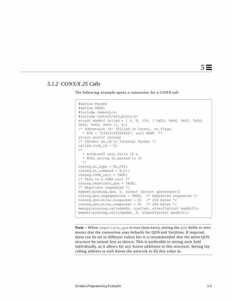
5.1.2 CONS/X.25 Calls
The following example opens a connection for a CONS call:
Note – When negotiate_qos is true (non-zero), setting the QOS fields to zeromeans that the connection uses defaults for QOS and Facilities. If required,these can be set to different values but it is recommended that the entire QOSstructure be zeroed first as shown. This is preferable to setting each fieldindividually, as it allows for any future additions to this structure. Setting thecalling address to null leaves the network to fill this value in.
#define FALSE0#define TRUE1#include <memory.h>#include <netx25/x25_proto.h>struct xaddrf called = { 0, 0, {14, { 0x23, 0x42, 0x31, 0x56,0x56, 0x56, 0x56 }}, 0};/* Subnetwork "A" (filled in later), no flags, * DTE = "23423156565656", null NSAP */struct xcallf conreq;/* Convert sn_id to internal format */called.link_id = 0;/* * snidtox25 only fails if a * NULL string is passed to it */conreq.xl_type = XL_CTL;conreq.xl_command = N_CI;conreq.CONS_call = TRUE;/* This is a CONS call */conreq.negotiate_qos = TRUE;/* Negotiate requested */memset(&conreq.qos, 0, sizeof (struct qosformat));conreq.qos.reqexpedited = TRUE; /* Expedited requested */conreq.qos.xtras.locpacket = 8; /* 256 bytes */conreq.qos.xtras.rempacket = 8; /* 256 bytes */memcpy(&conreq.calledaddr, &called, sizeof(struct xaddrf));memset(&conreq.callingaddr, 0, sizeof(struct xaddrf));

5-6 SunLink X.25 8.0.2 Programmer’s Guide—October 1994
5
The message is then sent on the stream using the putmsg system call, with anycall user data being passed in the data part of the message:
At this stage, the application should wait for a response to the Call Request.The response may be either a Connect Confirmation or a Disconnect (rejection)message.
#define CUDFLEN 4struct strbuf, ctlblk, datblk;char cudf[CUDFLEN] = { 1, 0, 0, 0 };ctlblk.len = sizeof(struct xcallf);ctlblk.buf = (char *) &conreq;datblk.len = CUDFLEN;datblk.buf = cudf;if (putmsg(x25_fd, &ctlblk, &datblk, 0) < 0 ) {
perror("Call putmsg");exit(1);}

Streams Programming Examples 5-7
5
#define DBUFSIZ 128#define CBUFSIZ MAX(sizeof(struct xccnff), sizeof(struct xdiscf))int getflags = 0;S_X25_HDR*ind_msg;char ctlbuf[CBUFSIZ], datbuf[DBUFSIZ];struct xccnff *ccnf;struct qosformat qos;ctlblk.maxlen = CBUFSIZ;ctlblk.buf = ctlbuf;datblk.maxlen = DBUFSIZ;datblk.buf = datbuf;for(;;) {
if (getmsg(x25_fd, &ctlblk, &datblk, &getflags) < 0) {perror("Getmsg fail");
exit(1);}ind_msg = (S_X25_HDR *) ctlbuf;if (ind_msg->xl_type != XL_CTL)
continue;switch (ind_msg->xl_command) {
case N_CC:/* ........ Process the Connect Confirmation */
ccnf = ((struct xccnff *) ind_msg;if (ccnf -> negotiate_qos ) {
bcopy (&qos, ccuf->qos, sizeof (struct qosformat));if (qos -> reqexpedited )printf("Request Expedited set\n");elseprintf("Request Expedited not set\n");}
else {/* indicated values have been accepted */
}return;
case N_DI:perror("Connection rejected");exit(1);
default:continue;
}}
5-8 SunLink X.25 8.0.2 Programmer’s Guide—October 1994
5
In the preceding example, getmsg is used to retrieve the next message fromthe stream head. This is done in a loop, until either a Connect Confirmmessage, indicating successful completion, is received, or a DisconnectIndication, showing that the connect attempt was rejected.
Note – The facility and QOS values indicated in the Connect Confirmation arethose that are used for the duration of the connection.
It is possible to abort the connect request before a response is received. Theapplication can do this by sending a Disconnect Request message (see “Closinga Connection” on page 5-15). If this is done, the application should read anddiscard all messages from the stream until it receives the disconnectacknowledgement (described inSection 3.9, “Disconnect Request/Indication,”on page 3-9). After a rejection or connect abort the stream remains open, andcan be used, for example, to make further connection attempts.
5.2 Data TransferIn the data transfer phase, access is given to:
• the Q-bit, to support X.29-like services
• the M-bit, to signal packet fragmentation
• the D-bit, to request confirmation of data delivery
• Expedited data, to support X.29 and CONS.
Normal and Q-bit data is sent and received using the N_Data message andmay be acknowledged using the N_DAck message. Expedited data uses theN_EData message, and is acknowledged using an N_EAck message. Thefollowing subsections show examples of code for data transfer:

Streams Programming Examples 5-9
5
5.2.1 Sending Data
Once a connection has been successfully opened on a stream, sending a datapacket is straightforward:
Normally, the call to putmsg blocks if there are flow control conditions in theconnection which lead to either a full queue at the stream head, or a lack ofstreams resources. Blocking due to a full queue can be avoided if the stream isopened with the option O_NDELAY flagged. In this case, putmsg returnsimmediately, and the failure is signalled by a return value (retval ) ofEAGAIN.
This procedure allows the application to carry out other processing (forexample, receiving data) before trying again. The best method to use dependson the nature of the application.
5.2.2 Receiving Data
In the same way as sending data, data reception is straightforward. When datais received with the D-bit set, action may be required by the application. Whenthe initial Call Request is sent, it may request that data confirmation be at theapplication-to-application level. If application-to-application confirmation isagreed upon, then on receiving a packet with the D-bit set, it must beacknowledged by sending a Data Acknowledgement (N_DAck) message.
#define DBUFSIZ 128struct xdataf data;char datbuf[DBUFSIZ];int retval;/* Copy data into datbuf[] here*/data.xl_type = XL_DAT;data.xl_command = N_Data;data.More = data.setQbit = data.setDbit = FALSE;ctlblk.len = sizeof(struct xdataf);ctlblk.buf = (char *) &data;datblk.len = DBUFSIZ;datblk.buf = datbuf;retval = putmsg(x25_fd, &ctlblk, &datblk, 0);
5-10 SunLink X.25 8.0.2 Programmer’s Guide—October 1994
5
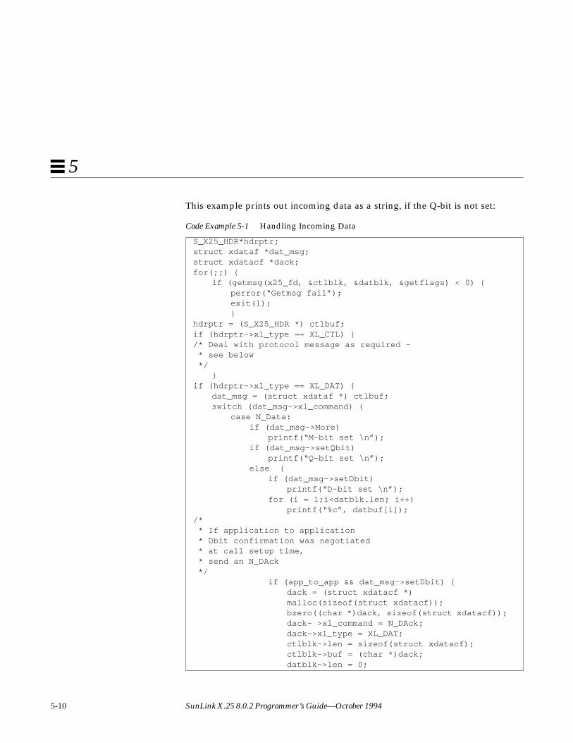
This example prints out incoming data as a string, if the Q-bit is not set:
Code Example 5-1 Handling Incoming Data
S_X25_HDR*hdrptr;struct xdataf *dat_msg;struct xdatacf *dack;for(;;) {
if (getmsg(x25_fd, &ctlblk, &datblk, &getflags) < 0) {perror(“Getmsg fail”);exit(1);}
hdrptr = (S_X25_HDR *) ctlbuf;if (hdrptr->xl_type == XL_CTL) {/* Deal with protocol message as required - * see below */
}if (hdrptr->xl_type == XL_DAT) {
dat_msg = (struct xdataf *) ctlbuf;switch (dat_msg->xl_command) {
case N_Data:if (dat_msg->More)
printf(“M-bit set \n”);if (dat_msg->setQbit)
printf(“Q-bit set \n”);else {
if (dat_msg->setDbit)printf(“D-bit set \n”);
for (i = 1;i<datblk.len; i++)printf(“%c”, datbuf[i]);
/* * If application to application * Dbit confirmation was negotiated * at call setup time, * send an N_DAck */
if (app_to_app && dat_msg->setDbit) {dack = (struct xdatacf *)malloc(sizeof(struct xdatacf));bzero((char *)dack, sizeof(struct xdatacf));dack- >xl_command = N_DAck;dack->xl_type = XL_DAT;ctlblk->len = sizeof(struct xdatacf);ctlblk->buf = (char *)dack;datblk->len = 0;

Streams Programming Examples 5-11
5
5.2.3 Expedited Data
The preceding example allows for the possibility of receiving expedited datamessages (which are carried in X.25 interrupt packets). These must be dealtwith appropriately. Since only one expedited data packet can be outstanding inthe connection at any time, its sender is prevented from sending any furthersuch messages until the receiver has acknowledged it. The receiver does this bysending an Expedited Acknowledgement (EAck) message.
The EAck is sent in much the same way as an ordinary data packet, but withno data part. If the application does not need to use the expedited datacapability, then other appropriate responses to receiving an EData message areto reset or close the connection. (See Section 5.2.4, “Resets,” on page 5-13 andSection 5.3, “Closing a Connection,” on page 5-15.)
When sending expedited data, the application must wait for anacknowledgement before requesting further expedited transmissions.
datblk->buf = (char *)0;putmsg(x25_fd, &ctlblk, &datblk, &getflags);}
} /* end else */break;
case N_EData:printf(“***Expedited data received \n”);
/* Must deal with */break;
case N_DAck:printf(“***Data Acknowledgement received \n”);break;
default:break;
} /* end switch */} /* end if */
} /* end for */
Code Example 5-1 Handling Incoming Data (Continued)

5-12 SunLink X.25 8.0.2 Programmer’s Guide—October 1994
5
#include <sys/net/x25_proto.h>#define EXPLEN 4struct xed atafexp;char expdata[]= {1, 2, 3, 4};exp.xl_type= XL_CTL;exp.xl_command= N_Edata;ctlblk.len= sizeof (struct xedataf);ctlblk.buf= (char *) &exp;datblk.len= EXPLEN;datblk.buf= expdata;if (putmsg(x25_fd, &ctlblk, &datblk, 0) < 0) {
error("Exp putmsg");exit(1);}
for (;;) {if (getmsg(x25_fd, &ctlblk, &datblk, &getflags) < 0) {perror("Getmsg fail");exit(1);}
hdrptr = (S_X25_HDR *) ctlbuf;if (hdrptr->xl_type == XL_CTL) {/* Deal with protocol message as required */
}if (hdrptr->xl_type == XL_DAT) {
dat_msg = (struct xdataf *) ctlbuf;switch (dat_msg->xl_command) {
case N_Data:/* process more data */
break;case N_EData:
printf("***Expedited data received \n");/* Must deal with */.... send N_EAck ....
break;case N_EAck: /* Expedited data received */
/* Further N_Edata can now be sent */break;
default:break;
}}
Streams Programming Examples 5-13
5
5.2.4 Resets
Resets can be dealt with in a similar way to interrupts, except that there is nodata passed with a Reset Request. When a Reset Request is issued, theapplication must wait for the acknowledgement, as for an expedited request.However, until this is received, the only action that can be taken is to issue aDisconnect Request.
The diagnostic field in a Reset Request should be filled in with the reason forissuing the reset. Standard values for this are defined in the include file<netx25/x25_proto.h> , although the application can set any value. SeeSection A.2, “Error Codes,” on page A-2 for more details.
When a Reset Indication is received, there are only two valid actions that maybe taken:
• send a Reset Confirmation message to acknowledge the reset
• send a Disconnect Request
In this situation, pending data is flushed from the queue.
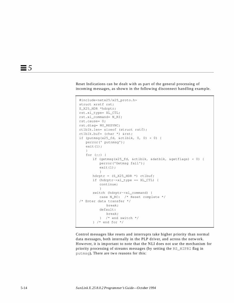
5-14 SunLink X.25 8.0.2 Programmer’s Guide—October 1994
5
Reset Indications can be dealt with as part of the general processing ofincoming messages, as shown in the following disconnect handling example.
Control messages like resets and interrupts take higher priority than normaldata messages, both internally in the PLP driver, and across the network.However, it is important to note that the NLI does not use the mechanism forpriority processing of streams messages (by setting the RS_HIPRI flag inputmsg ). There are two reasons for this:
#include<netx25/x25_proto.h>struct xrstf rst;S_X25_HDR *hdrptr;rst.xl_type= XL_CTL;rst.xl_command= N_RI;rst.cause= 0;rst.diag= NU_RESYNC;ctlblk.len= sizeof (struct rstf);ctlblk.buf= (char *) &rst;if (putmsg(x25_fd, &ctlblk, 0, 0) < 0) {
perror(" putnmsg");exit(1);}for (;;) {
if (getmsg(x25_fd, &ctlblk, &datblk, &getflags) < 0) {perror("Getmsg fail");exit(1);}
hdrptr = (S_X25_HDR *) ctlbuf;if (hdrptr->xl_type == XL_CTL) {
continue;}
switch (hdrptr->xl_command) {case N_RC: /* Reset complete */
/* Enter data transfer */break;
default:break;
} /* end switch */} /* end for */

Streams Programming Examples 5-15
5
• The stream head can only hold one incoming priority message (the first).This is inappropriate in certain situations where several of these messagesmay follow each other in quick succession. For example, a Reset may befollowed immediately by a Disconnect.
• An outgoing priority message would overtake any data which is queuedwaiting to be sent. It is possible that data could then be sent after thepriority message (for example, a reset), which would lead to an NLIprotocol violation.
5.3 Closing a ConnectionThis section covers remote and local disconnects.
5.3.1 Remote Disconnect
If, during a connection, the remote end initiates a Disconnect, then aDisconnect Indication (N_DI ) message (or possibly an N_Abort message, seeSection 3.11, “Abort Indication,” on page 3-11) is received at the NLI. Theapplication need not acknowledge this message since, after sending aDisconnect, the X.25 driver silently discards all messages received except forconnect and accept messages. These are the only meaningful X.25 messages onthe stream after disconnection.
The receiver of a Disconnect Indication should ensure that enough room isavailable in the getmsg call to receive all parameters and, when present, up to128 bytes of Clear User Data. Handling such a Disconnect event would
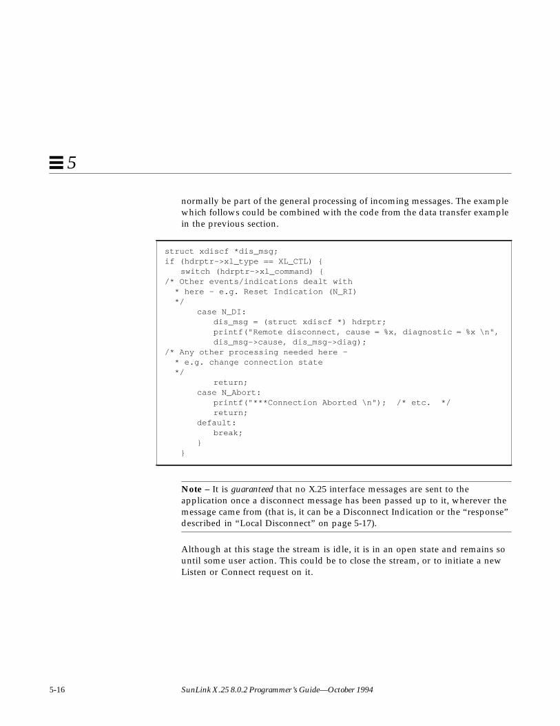
5-16 SunLink X.25 8.0.2 Programmer’s Guide—October 1994
5
normally be part of the general processing of incoming messages. The examplewhich follows could be combined with the code from the data transfer examplein the previous section.
Note – It is guaranteed that no X.25 interface messages are sent to theapplication once a disconnect message has been passed up to it, wherever themessage came from (that is, it can be a Disconnect Indication or the “response”described in “Local Disconnect” on page 5-17).
Although at this stage the stream is idle, it is in an open state and remains sountil some user action. This could be to close the stream, or to initiate a newListen or Connect request on it.
struct xdiscf *dis_msg;if (hdrptr->xl_type == XL_CTL) {
switch (hdrptr->xl_command) {/* Other events/indications dealt with * here - e.g. Reset Indication (N_RI) */
case N_DI:dis_msg = (struct xdiscf *) hdrptr;printf("Remote disconnect, cause = %x, diagnostic = %x \n",dis_msg->cause, dis_msg->diag);
/* Any other processing needed here - * e.g. change connection state */
return;case N_Abort:
printf("***Connection Aborted \n"); /* etc. */return;
default:break;
}}

Streams Programming Examples 5-17
5
5.3.2 Local Disconnect
To initiate a Disconnect on a connection, the application should send aDisconnect Request (N_DI ) message on the stream. Unless this is being used toreject an incoming call (see “Handling the Connect Indication” on page 5-22),the X.25 driver signals that it has observed the message. It does this by sendinga Disconnect Confirm upstream when it receives the Clear Confirm. In thisway, the upper components can be certain that no messages will follow theDisconnect.
In the case of rejection, the connection identifier supplied on the ConnectIndication must be returned in the disconnect message. The disconnect (reject)is not acknowledged in this case.
As in the case of a remote disconnection, once the response has been receivedthe stream becomes idle, and remains in this state until the application sendsout another control message. This may be to close the stream, or to initiate anew Listen or Connect request on it. The application should, however, not sendany of these messages until it receives the Disconnect Response.

5-18 SunLink X.25 8.0.2 Programmer’s Guide—October 1994
5
As described in Section 3.9, “Disconnect Request/Indication,” on page 3-9, adisconnect collision may occur. If this happens, no Disconnect Confirm is sent.
/* Coded and sent disconnect request, process response */struct xdiscf *dis_ind;struct xdcnff *dis_cnf;struct extraformat *xqos = (struct extraformat *)0;if ( hdrptr->xl_type == XL_CTL ) {
switch( hdrptr->xl_command ) {/* Disconnect Collision */
case N_DI:dis_ind = (struct xdiscf*)hdrptr;xqos = &dis_ind->indicatedqos.xtras;break;
/* Disconnect Confirmation */case N_DC:
dis_cnf = (struct xdcnff*)hdrptr;xqos = &dis_cnf->indicatedqos.xtras;break;
default:return;
}if ( xqos ) {
/* * Print any charging information returned */
if ( xqos->chg_cd_len ) {/* Print out Call Duration from chg_cd_field */
}if ( xqos->chg_mu_len ) {
/* Print out Monetary Unit from chg_mu_field */}
if ( xqos->chg_sc_len ) {/* Print out Segment Count from chg_sc_field */
}} /* end if (xqos) */
} /* end if (hdrptr->xl_type==XL_CTL) */
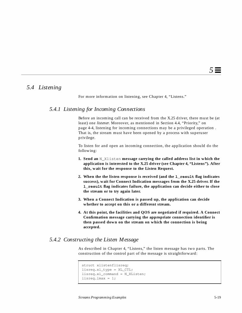
Streams Programming Examples 5-19
5
5.4 ListeningFor more information on listening, see Chapter 4, “Listens.”
5.4.1 Listening for Incoming Connections
Before an incoming call can be received from the X.25 driver, there must be (atleast) one listener. Moreover, as mentioned in Section 4.4, “Priority,” onpage 4-4, listening for incoming connections may be a privileged operation .That is, the stream must have been opened by a process with superuserprivilege.
To listen for and open an incoming connection, the application should do thefollowing:
1. Send an N_Xlisten message carrying the called address list in which theapplication is interested to the X.25 driver (see Chapter 4, “Listens”). Afterthis, wait for the response to the Listen Request.
2. When the the listen response is received (and the l_result flag indicatessuccess), wait for Connect Indication messages from the X.25 driver. If thel_result flag indicates failure, the application can decide either to closethe stream or to try again later.
3. When a Connect Indication is passed up, the application can decidewhether to accept on this or a different stream.
4. At this point, the facilities and QOS are negotiated if required. A ConnectConfirmation message carrying the appropriate connection identifier isthen passed down on the stream on which the connection is beingaccepted.
5.4.2 Constructing the Listen Message
As described in Chapter 4, “Listens,” the listen message has two parts. Theconstruction of the control part of the message is straightforward:
struct xlistenflisreq;lisreq.xl_type = XL_CTL;lisreq.xl_command = N_XListen;lisreq.lmax = 1;

5-20 SunLink X.25 8.0.2 Programmer’s Guide—October 1994
5
In this example, lmax has the value of 1, indicating that only one ConnectIndication is to be handled at a time.
The data part of the message should be filled with the sequence of bytes thatspecify the Call User Data string and address(es) which are to be listened for.The simplest case for this would be to set “Don’t Care” values for both theCUD and address:
Alternatively, to set the CUD to match exactly the (X.29) value defined in thearray cudf[] earlier (0x01000000), and the NSAP to match any sequencestarting 0x80 , 0x00 , the following would be used:
int lislen;char lisbuf[MAXLIS];lisbuf[0] = X25_DONTCARE; /* l_cumode*/lisbuf[1] = X25_DONTCARE; /* l_mode*/lislen = 2;
lislen = 0;lisbuf[lislen++] = X25_IDENTITY; /* l_cumode */lisbuf[lislen++] = CUDFLEN; /* l_culength */memcpy(&(lisbuf[lislen]), cudf, CUDFLEN); /* l_cubytes */lislen += CUDFLEN;lisbuf[lislen++] = X25_STARTSWITH; /* l_mode */lisbuf[lislen++] = X25_NSAP; /* l_type */lisbuf[lislen++] = 4; /* l_length */lisbuf[lislen++] = 0x80; /* l_add */lisbuf[lislen++] = 0x00;

Streams Programming Examples 5-21
5
Or, to accept any CUD Field, with a DTE of 2342315656565:
Note – The l_add field uses packed hexadecimal digits and the l_lengthvalue is actually the number of semi-octets whereas the l_culength fieldspecifies the length of the l_cubytes field in octets.
Next, send the Listen Request down the open stream:
#define MY_DTE_LEN 13#define MY_DTE_OCTETS 7char my_dte[MY_DTE_OCTETS] ={0x23,0x42,0x31,0x56,0x56,0x56,0x50};lislen = 0;lisbuf[lislen++] = X25_DONTCARE; /* l_cumode */lisbuf[lislen++] = X25_IDENTITY; /* l_mode */lisbuf[lislen++] = X25_DTE; /* l_type */lisbuf[lislen++] = MY_DTE_LEN; /* l_length */memcpy(&(lisbuf[lislen]), my_dte, MY_DTE_OCTETS); /* l_add */lislen += MY_DTE_OCTETS;
ctlblk.len = sizeof(struct xlistenf);ctlblk.buf = (char *) &lisreq;datblk.len = lislen;datblk.buf = lisbuf;if (putmsg(x25_fd, &ctlblk, &datblk, 0) < 0) {
perror("Listen putmsg failure");return -1;}

5-22 SunLink X.25 8.0.2 Programmer’s Guide—October 1994
5
Finally, wait for the listen response; the result flag indicates success or failure:
Cancelling a Listen Request can be done in the same way, except that no data ispassed with the request. It simply cancels all successful Listens that have beenmade on that stream.
5.4.3 Handling the Connect Indication
Once the listening application has received a Listen Response indicatingsuccess, it should wait for incoming Connect Indications. When an N_CImessage arrives, the application should inspect its parameters: address, calluser data, facilities, quality of service, and so on, then decide whether to acceptor reject the connection.
#define DBUFSIZ 128#define CBUFSIZ MAX( sizeof(struct xccnff), sizeof(structxdiscf) )struct xlistenf *lis_msg;ctlblk.maxlen = CBUFSIZ; /* See 4.1 above for declarations */ctlblk.buf = ctlbuf;datblk.maxlen = DBUFSIZ;datblk.buf = datbuf;for(;;) {
if (getmsg (x25_fd, &ctlblk, &datblk, &getflags) < 0) {perror("Listen getmsg failure");return -1;}
lis_msg = (struct xlistenf *) ctlbuf;if ((lis_msg->xl_type == XL_CTL) && (lis_msg->xl_command ==
N_XListen))if (lis_msg->l_result != 0) {
printf("Listen command failed \n");return -1;}
else {printf("Listen command succeeded \n");return 0;}
}

Streams Programming Examples 5-23
5
AcceptanceIf accepting, the listening application can do so either on the stream theindication arrived on, or on some other stream. This other stream can be onewhich is already open and free, or it can be newly opened.
Whatever method is used for the accept, the identifier conn_id in the ConnectIndication message must be copied into the accept message for matching by theX.25 driver. If this identifier in the accept message does not match, aDisconnect is sent to the accepting application. This causes the resource tohang on the stream on which the incoming call was sent, since the connectionis never accepted.
RejectionA listening application can reject the call by sending a N_Disc message downthe stream on which the Connect Indication arrived. A Connect Indicationcannot be rejected on a different stream. Again, the connection identifier mustbe quoted in the message for matching, since there may be several ConnectIndications passed to the listening application. If there is no match for therejection, the message is silently discarded.
The rejecting listener can request one of two actions in response to thedisconnect:
• Request immediate disconnect. Set the reason field to NU_PERMANENT(0xF5).
• Search for further matching listeners. Set the reason field to any valueexcept 0xF5.
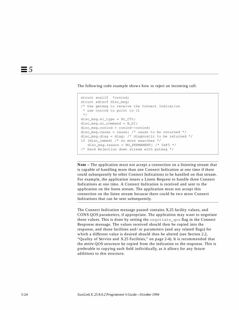
5-24 SunLink X.25 8.0.2 Programmer’s Guide—October 1994
5
The following code example shows how to reject an incoming call:
Note – The application must not accept a connection on a listening stream thatis capable of handling more than one Connect Indication at one time if therecould subsequently be other Connect Indications to be handled on that stream.For example, the application issues a Listen Request to handle three ConnectIndications at one time. A Connect Indication is received and sent to theapplication on the listen stream. The application must not accept thisconnection on the listen stream because there could be two more ConnectIndications that can be sent subsequently.
The Connect Indication message passed contains X.25 facility values, andCONS QOS parameters, if appropriate. The application may want to negotiatethese values. This is done by setting the negotiate_qos flag in the ConnectResponse message. The values received should then be copied into theresponse, and those facilities and/or parameters (and any related flags) forwhich a different value is desired should then be altered (see Section 2.2,“Quality of Service and X.25 Facilities,” on page 2-4). It is recommended thatthe entire QOS structure be copied from the indication to the response. This ispreferable to copying each field individually, as it allows for any futureadditions to this structure.
struct xcallf *conind;struct xdiscf disc_msg;/* Use getmsg to receive the Connect Indication * use conind to point to it */disc_msg.xl_type = XL_CTL;disc_msg.xl_command = N_DI;disc_msg.conind = conind->conind;disc_msg.cause = cause; /* cause to be returned */disc_msg.diag = diag; /* diagnostic to be returned */if (disc_immed) /* no more searches */
disc_msg.reason = NU_PERMANENT; /* 0xF5 *//* Send Rejection down stream with putmsg */

Streams Programming Examples 5-25
5
An example of negotiation is shown below. Here all the values are copied asindicated, except the packet size, which is negotiated down to 256 if it isflagged as negotiable, and is greater than 256:
Alternatively, the application may decide to accept (agree with) the indicatedvalues, in which case the negotiate_qos flag is set to zero.
5.4.4 Reusing the Listen Stream
If a connection is never established on a listening stream (using a matchingaccept) then that stream remains listening on the address list supplied. On theother hand, once an established connection has been disconnected, the streamdoes not return to a listening state. Instead, it remains open in an idle state. Ifthe application needs to listen again, then the listen message must be re-sent.Rejection does not alter the listening state of the stream.
struct xcallf *conind;struct xccnff conresp;/* Do a getmsg etc to receive the Connect Indication, * assign conind to point to it. */conresp.xl_type = XL_CTL;conresp.xl_command = N_CC;conresp.conn_id = conind->conn_id; /* Connection identifier */conresp.CONS_call = TRUE /* This is a CONS call */memset(&conresp.responder, 0, sizeof(struct xaddrf));/* Let network fill in responding addr */conresp.negotiate_qos = TRUE;memcpy (&conresp.rqos, &conind->qos, sizeof (struct qosformat));if (conind->qos.xtras.pwoptions & NEGOT_PKT) {
if (conind->qos.xtras.rempacket > 8)conresp.rqos.xtras.rempacket = 8; /* 256 = 2v’-.2’8v’+.2’
*/if (conind->qos.xtras.locpacket > 8)
conresp.rqos.xtras.locpacket = 8;}
/* Set any other values to be negotiated here, * then send the response down with a putmsg. */

5-26 SunLink X.25 8.0.2 Programmer’s Guide—October 1994
5
5.5 PVC OperationThe following subsections describe the procedures necessary for an applicationto operate a PVC on the X.25 PLP Driver.
5.5.1 Attaching a PVC
To attach a PVC on an open stream, an application must:
1. Allocate a PVC_attach structure.
2. Supply the structure with the appropriate reqackservice andreqnsdulimit parameters. These parameters are used for the duration ofthe connection.
3. Set the appropriate subnetwork and logical channel identifiers.
4. Pass the attach request down to the X.25 Driver.
5. Wait for the attach accept or rejection.
For example:
The message is then sent on the stream using the putmsg system call:
#include <sys/stropts.h>#include <netx25/x25_proto.h>struct pvcattfattach = { XL_CTL, N_PVC_ATTACH, 1, 0, 0, 0, 0 };/* Logical Channel 1 * No request for Receipt Ack or nsdulimit */struct strbufctlblk; /* Convert sn_id to internal format */attach.link_id = 0;ctlblk.len = sizeof(struct pvcattf);ctlblk.buf = (char *) &attach;
if (putmsg (x25_fd, &ctlblk, 0, 0) < 0) { perror(“Attach putmsg”); exit(1); }

Streams Programming Examples 5-27
5
At this stage, the application should wait for a response to the attach. Theresponse may indicate either a successful attachment or a rejection.
In this example, getmsg is used to retrieve the next message from the streamhead. This is done in a loop, until either the attach is confirmed successful orrejected. Although the processing of the attach is not shown here, it is
#define DBUFSIZ 128#define CBUFSIZsizeof(struct pvcattf)int getflags;struct pvcattf *ind_msg;char ctlbuf[CBUFSIZ], datbuf[DBUFSIZ];ctlblk.maxlen = CBUFSIZ;ctlblk.buf = ctlbuf;datblk.maxlen = DBUFSIZ;datblk.buf = datbuf;for(;;) {
if (getmsg(x25_fd, &ctlblk, &datblk, &getflags) < 0) {perror(“Getmsg fail”);
exit(1);}
ind_msg = (struct pvcattf *) ctlbuf;if (ind_msg->xl_type != XL_CTL)
continue;switch (ind_msg->xl_command) {
case N_PVC_ATTACH:switch (ind_msg->result_code) {
case PVC_SUCCESS:/*...... Process the attach */
return(1);case PVC_NOSUCHSUBNET:case PVC_CFGERROR:case PVC_PARERROR:case PVC_BUSY:
/*...... Process the reject */return(0);
default:printf(“Unknown PVC message\n”);exit(1);
}}
}

5-28 SunLink X.25 8.0.2 Programmer’s Guide—October 1994
5
recommended that the application send a Reset Request (see Section 3.7, “ResetRequest/Indication,” on page 3-7) and wait for the Reset Confirm (seeSection 3.8, “Reset Response/Confirm,” on page 3-8) before proceeding withthe data transfer. The example given in “Resets” on page 5-13 shows the codeused to send a Reset and handle the acknowledgement. This synchronizes theX.25 PLP drivers at each end of the PVC. The example does not illustrate allpossible result_code cases.
It is possible to abort the Attach Request before a response is received. Theapplication can do this by sending a Detach Request message (see Section 5.5.3,“Detaching a PVC”). If this is done, the application should read and discard allmessages from the stream until it receives the detach acknowledgement.
After a rejection or an attach abort the stream remains open and can be used,for example, to make further attach attempts.
5.5.2 PVC Data Transfer
The transfer of data over a Permanent Virtual Circuit is exactly the same, to theapplication, as for Virtual Circuits. Section 5.2, “Data Transfer” contains adescription of the procedures involved.
5.5.3 Detaching a PVC
The procedure used to detach a PVC differs for the remote and local cases, sothese are described separately here.
Remote DetachIf, during a connection, the remote end initiates a detach, then a ResetIndication (seeSection 3.7, “Reset Request/Indication,” on page 3-7) message isreceived at the NLI. The application should acknowledge this with a ResetResponse (see Section 3.8, “Reset Response/Confirm,” on page 3-8). Handlingsuch an event would normally be part of the general processing of incomingmessages.
After sending the Reset Response, the application is still attached to its PVCand remains so until it initiates a local detach.

Streams Programming Examples 5-29
5
Local DetachTo initiate a detach on a connection, the application should send a DetachRequest (N_PVC_DETACH) message on the stream. The X.25 driver signals thatit has observed the message by sending a Detach upstream. In this way, theupper component can be certain that no messages follow the Detach. Forexample:
As is the case for a Remote Detach, once the response has been received thestream becomes idle. It enters an open state, in which it remains until theapplication commands otherwise. This could be to close the stream, or toinitiate a new Attach Request on it. The application should, however, wait untilit receives the Detach Response.
struct pvcdetfdetach = { XL_CTL, N_PVC_DETACH, 0 };ctlblk.len = sizeof(struct pvcdetf);ctlblk.buf = (char *) &detach;if (putmsg(x25_fd, &ctlblk, 0, 0) < 0) {
perror("Detach putmsg");exit(1);}

5-30 SunLink X.25 8.0.2 Programmer’s Guide—October 1994
5

6-1
Support Library 6
There are a number of programming routines which, while not strictly a part ofthe X.25 networking code, are invaluable in writing network applications.There are man pages for each of these routines. With /opt/SUNWconn/man aspart of your MANPATH environment variable, these man pages become availableto you.
The library resides in /opt/SUNWconn/lib/libsx25.a . To link against thelibrary use a command such as the following:
The support library consists of the following routines:
padtosConverts a network pad database structure into a string.
stox25Converts a string containing an X.25 dot format address to an X.25 xaddrfstructure.
x25tosConverts an X.25 xaddrf structure to a string containing an X.25 dot formataddress.
equalx25Tests if two X.25 xaddrf structures are identical.
hostname% cc -o test test.c -L/opt/SUNWconn/lib -lsx25
6-2 SunLink X.25 8.0.2 Programmer’s Guide—October 1994
6
linkidtoX25Converts a string containing a link identifier to the internal format used inX.25 primitives.
x25tolinkidConverts a link identifier in the internal format used in X.25 primitives to astring.
getnettypeReturns type of network (LAN/WAN 1980/84/88) that is configured for aparticular link identifier.
Use the following routines to manipulate the network pad database file(/etc/SUNWconn/x25/padmapconf ):
getpadbyaddrSearches the network pad database file until an entry containing the givenaddress is found. A pointer to the entry is returned.
getpadbystrSearches the network pad database file until an entry containing the givenname is found. A pointer to the entry is returned.
getpadentReads the next line of the network pad database, opening the file ifnecessary.
setpadentOpens and rewinds the network pad database file.
endpadentCloses network pad database file after use.
Use the following routines to manipulate the X.25 host database file(/etc/SUNWconn/x25/xhosts ):
getxhostbyaddrSearches the X25 host database file until an entry containing the givenaddress is found. A pointer to the entry is returned.
getxhostbynameSearches the X25 host database file until an entry containing the given nameis found. A pointer to the entry is returned.

Support Library 6-3
6
getxhostentReads the next line of the X25 host database, opening the file if necessary.
setxhostentOpens and rewinds the X25 host database file.
endxhostentCloses network X25 hosts file after use.

6-4 SunLink X.25 8.0.2 Programmer’s Guide—October 1994
6

7-1
NLI Management ioctls 7
Note – For more detailed information on STREAMS in general, and the use ofioctls in particular, refer to the STREAMS Programmer’s Guide.
7.1 Management-related Upper Stream Message StructuresThe following list of message structures describes those messages which can beused for status and other information. They differ from the other NLImessages in that they are not concerned directly with the communicationbetween upper components and the X.25 protocol machine.
7.1.1 Management Structures and Interface
The management of the X.25 multiplexor is performed through the ioctl systemcall mechanism on a control stream using the I_STR ioctl of streams. (This useof the ioctl mechanism is in addition to the normal use in stream operationslike PUSH or LINK .)
The iocblk structure contains a ioctl type field the values of which aredescribed in the following paragraphs. The M_DATA portion, when present,supplies any necessary user-provided data.
For security and protection, the initiator of many of these ioctls must be super-user, that is, the effective user id number in the iocblk must be zero. The ioctldescriptions specify whether super-user privilege is required.

7-2 SunLink X.25 8.0.2 Programmer’s Guide—October 1994
7
As is standard within the streams environment, success or failure of the ioctlfunction is indicated by sending, respectively, an M_IOCACK or M_IOCNAKmessage upstream.
The wlcfg database which is referenced in the following sections is describedin detail in Section 7.2, “Configurable Parameters,” on page 7-20. For anexample of how a user process makes an I_STR ioctl call, see the example forthe N_linkent ioctl in the following subsection.
7.1.1.1 N_linkent ioctl
This ioctl is sent downstream by the x25netd process to configure a newlylinked driver below the X.25 multiplexor. It supplies the parameters necessaryto identify the link via the identifier and to register the mode of the lowerdriver. You must be super-user to make this ioctl.
The data contained in the ioctl is in the format:
The fields are:
lmuxidThis is the unique link index supplied by the streams I_LINK ioctl returnedwhen the lower driver is linked below the X.25 multiplexor.
struct xll_reg { struct ll_reg lreg; int lmuxid;};

NLI Management ioctls 7-3
7
lregThis is anll_reg structure:
The fields of the registration message structure are used as follows:
ll_typecontains LL_REG;
ll_classidentifies the class of link level required, and has the value LC_LLC1,LC_LLC2; or one of LC_LAPBDTE, LC_LAPBXDTE, LC_LAPBDCE orLC_LAPBXDCE for LAPB operation (suffix ’X’ selects extended (modulo 128)operation); or one of LC_LAPDTE or LC_LAPDCE for LAP operation;
ll_regstatusis ignored (it is used later to return the registration status);
ll_ppaidentifies the link concerned. (PPA is a DLPI abbreviation for “PhysicalPoint of Attachment”.)
ll_mymacaddris ignored (it is used later [LLC only] to return the MAC address of the localstation).
ll_normalSAP[LLC only] is the normal SAP for LLC connections on the stream;
ll_loopbackSAP[LLC only] is the loopback SAP, used only for loopback connections;
struct ll_reg { uint8 ll_type; uint8 ll_class; uint8 ll_regstatus; uint8 ll_spare; uint32 ll_ppa; uint8 ll_mymacaddr; uint8 ll_normalSAP; uint8 ll_loopbackSAP;};

7-4 SunLink X.25 8.0.2 Programmer’s Guide—October 1994
7
If the link level accepts the registration, it will set ll_regstatus toLS_SUCCESS, place the local MAC address in ll_mymacaddr [LLC only] andreturn the registration message otherwise unchanged.
If the registration is rejected, for example because one of the specified SAPvalues has already been registered, the reason for rejection will be set as anerror number into ll_regstatus , and the message returned.
The value of ll_regstatus on return will be one of:• LS_SUCCESS
• LS_SSAPINUSE
• LS_EXHAUSTED
A user process makes the N_linkent ioctl call as follows:
/* * Send an N_linkent ioctl down to the X.25 multiplexor. * ’s’ is a stream to the X.25 multiplexor. * ’reg’ contains the necessary registration parameters. */intdo_linkent(s, reg) int s; struct xll_reg *reg;{ struct strioctl strioc;
strioc.ic_cmd = N_linkent; strioc.ic_timout = -1; strioc.ic_len = sizeof(struct xll_reg); strioc.ic_dp = (char *) reg; if (ioctl(s, I_STR, &strioc) < 0) { return (-1); } return (0);}

NLI Management ioctls 7-5
7
7.1.1.2 N_linkconfig ioctl
This ioctl is used to configure the wlcfg database for a link. The wlcfgdatabase appropriate to a link is carried as the M_DATA part of the ioctlN_linkconfig . The U_LINK_ID field in the wlcfg structure specifies the linkto be configured. You must be super-user to make this ioctl.
The wlcfg structure is documented in Section 7.2, “Configurable Parameters,”on page 7-20.
Note – Certain elements in the configuration database, if altered while calls areactive, could result in unpredicatable behavior. Specifically, alteration of thevirtual circuit channel ranges and default window and packet sizes shouldonly be made with extreme caution.
7.1.1.3 N_linkread ioctl
This ioctl is used to extract the wlcfg database for a link in a running systemfor examination. The wlcfg database is returned within the M_DATA part of theN_linkread ioctl. Care must be taken to ensure that there is enough space inthe data area to receive the copy of the structure. A non-privileged user caninvoke this ioctl.
7.1.1.4 N_linkmode ioctl
This ioctl is used to read or change the SUB_MODES field of a particular wlcfgdatabase appropriate to a link. This configuration ioctl is used to altercharacteristics of a link’s operation, for example, to temporarily bar incomingcalls. It is therefore recommended that the read ioctl be used before sendingthe alter ioctl. This procedure is intended to avoid inadvertent errors whichcould cause undesirable effects. The parameters are carried as the M_DATA partof the N_linkmode ioctl as follows:
struct linkoptformat { unsigned short newSUB_MODES; unsigned long U_LINK_ID; unsigned char rd_wr;};

7-6 SunLink X.25 8.0.2 Programmer’s Guide—October 1994
7
The fields are:
newSUB_MODEThis is the new SUB_MODES value in a write ioctl or the current value in aread ioctl.
U_LINK_IDThis is the field which identifies the particular link and must match one ofthe wlcfg database entries.
rd_wrThis determines read or write mode. A value of zero indicates read whilenon-zero indicates write.
In the case of read, the same structure is returned with the current value ofSUB_MODES for the link.
You must be super-user to make this ioctl.
7.1.1.5 N_getstats ioctl
This ioctl is used to read the statistics counts for the X.25 multiplexor sincenetwork startup or since they were last reset by an N_zerostats ioctl (seebelow). Statistics are maintained an a multiplexor basis—separate link statisticsare not available. There are no security restrictions on making this ioctl; any usercan do it.
The structure associated with this ioctl is an integer array of size mon_size , andeach array entry is a statistics or error count, with indices as follows:
Code Example 7-1 Indices to Statistics Array
/* ---- SYSTEM ERROR/MONITOR INDICES ---- */#define BadL2func 0#define Cantlzap 1#define L2badcc 2#define L2baddcnf 3#define L2badref 4#define L2report 5#define L2reset 6#define L3T25timeouts 7#define L3timeouts 8#define L3badAE 9#define L3badT20 10

NLI Management ioctls 7-7
7
#define L3badT24 11#define L3badT25 12#define L3badevent 13#define L3badgfi 14#define L3badlstate 15#define L3badltock2 16#define L3badrandom 17#define L3badxtock0 18#define L3clrbadstate 19#define L3conlt0 20#define L3deqfailed 21#define L3indnodata 23#define L3matrixcall 24#define L3nodb 25#define L3qoscheck 26#define L3outbad 27#define L3shortframe 28#define L3tabfault 29#define L3usererror 30#define L3usergone 31#define LNeednotneeded32#define NSUbadref 33#define NSUdtnull 34#define NSUednull 35#define NSUrefrange 36#define NeednotNeeded 37#define NoNRSrequest 38#define UDRbad 39#define Ubadint 40#define Unoint 41#define L2badtag 42#define L3baddiag 43
/* Statistical Information */
#define cll_coll 44 /* Call collision count (not rjc) */#define cll_uabort 45 /* Calls aborted by user b4 sent */#define rjc_buflow 46 /* Calls rejd no buffs b4 sent */#define rjc_coll 47 /* Calls rejd - collision DCE mode */#define rjc_failNRS 48 /* Calls rejd negative NRS resp */#define rjc_lstate 49 /* Calls rejd link disconnecting */#define rjc_nochnl 50 /* Calls rejd no lcns left */#define rjc_nouser 51 /* In call but no user on NSAP */
Code Example 7-1 Indices to Statistics Array
/* ---- SYSTEM ERROR/MONITOR INDICES ---- */

7-8 SunLink X.25 8.0.2 Programmer’s Guide—October 1994
7
#define rjc_remote 52 /* Call rejd by remote responder */#define rjc_u 53 /* Call rejd by NS user */#define dg_in 54 /* DIAG packets in */#define dg_out 55 /* DIAG packets out */#define p4_ferr 56 /* Format errors in P4 */#define rem_perr 57 /* Remote protocol errors */#define res_ferr 58 /* Restart format errors */#define res_in 59 /* Restarts received (inc DTE/DXE)*/#define res_out 60 /* Restarts sent (inc DTE/DXE) */#define vcs_labort 61 /* Circuits aborted via link event*/#define r23exp 62 /* Circuits hung by r23expiration */#define l2conin 63 /* Link level connect established */#define l2conok 64 /* LLC connections accepted */ #define l2conrej 65 /* LLC connections rejd */#define l2refusal 66 /* LLC connnect requests refused */#define l2lzap 67 /* Oper requests to kill link */#define l2r20exp 68 /* R20 retransmissionexpiration */#define l2dxeexp 69 /* DXE/connect expiration*/#define l2dxebuf 70 /* DXE resolv abort - no buffers */#define l2noconfig 71 /* No config base - error */#define xiffnerror 72 /* Upper i/f bad M_PROTO type */#define xifuserror 73 /* Upper user fn/state error */#define xintdisc 74 /* Internal disconnect events */#define xifaborts 75 /* Interface abort_vc called */#define PVCusergone 76 /* Count of non-user interactions */#define max_opens 77 /* highest no. simul. opens so far */#define vcs_est 78 /* VCs established since reset */#define bytes_in 79 /* Total data bytes received */#define bytes_out 80 /* Total data bytes sent */#define pkts_in 81 /* Count of data packets sent */#define pkts_out 82 /* Count of data packets received */#define res_conf_in 83 /* Restart Confirms received */#define res_conf_out 84 /* Restart Confirms sent */
/* GLOBAL totals for "per-VC" stats */
#define cll_in_g 85 /* Calls rcvd and indicated */#define cll_out_g 86 /* Calls sent */#define caa_in_g 87 /* Call established for outgoing */#define caa_out_g 88 /* Ditto - in call */
Code Example 7-1 Indices to Statistics Array
/* ---- SYSTEM ERROR/MONITOR INDICES ---- */
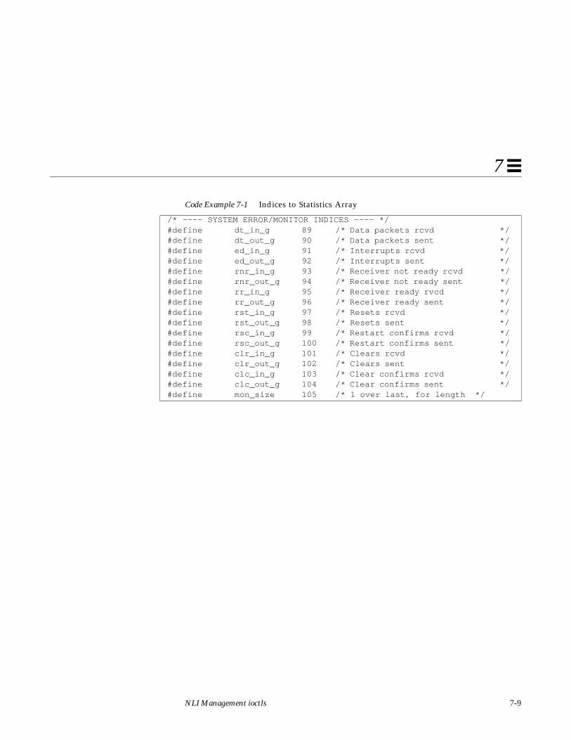
NLI Management ioctls 7-9
7
#define dt_in_g 89 /* Data packets rcvd */#define dt_out_g 90 /* Data packets sent */#define ed_in_g 91 /* Interrupts rcvd */#define ed_out_g 92 /* Interrupts sent */#define rnr_in_g 93 /* Receiver not ready rcvd */#define rnr_out_g 94 /* Receiver not ready sent */#define rr_in_g 95 /* Receiver ready rvcd */#define rr_out_g 96 /* Receiver ready sent */#define rst_in_g 97 /* Resets rcvd */#define rst_out_g 98 /* Resets sent */#define rsc_in_g 99 /* Restart confirms rcvd */#define rsc_out_g 100 /* Restart confirms sent */#define clr_in_g 101 /* Clears rcvd */#define clr_out_g 102 /* Clears sent */#define clc_in_g 103 /* Clear confirms rcvd */#define clc_out_g 104 /* Clear confirms sent */#define mon_size 105 /* 1 over last, for length */
Code Example 7-1 Indices to Statistics Array
/* ---- SYSTEM ERROR/MONITOR INDICES ---- */

7-10 SunLink X.25 8.0.2 Programmer’s Guide—October 1994
7
7.1.1.6 N_zerostats ioctl
This ioctl is used to reset the statistics counts for the X.25 multiplexor. You mustbe super-user to make this ioctl.
7.1.1.7 N_getVCstatus ioctl
The following structure is associated with this ioctl:
This ioctl is used to retrieve per-virtual circuit state and statistics, for all virtualcircuits currently active over all configured links. There are no securityrestrictions on making this ioctl; any user can do it.
The vcs field is an array of vcinfo structures, each of which contains the stateand statistics for an individual virtual circuit. The first_ent field is used toinform the X.25 multiplexor where to start or restart the table read. It shouldinitially be set to 0, to indicate starting at the beginning of the table. On return,it will be set to point the next entry to be gotten. The num_ent field is used bythe X.25 multiplexor to indicate the number of virtual circuit entries returnedin the vcs field. It should be set to 0 before making the ioctl.
struct vcstatusf { struct vcinfo vcs[MAX_VC_ENTS]; /* Data buffer */ int first_ent; /* Where to start search */ unsigned char num_ent; /* Number entries returned*/};

NLI Management ioctls 7-11
7
Here are the contents of thevcinfo structure:
The xstate field contains the state of the VC. Possible states are:
struct vcinfo { struct xaddrf rem_addr; /* = called for outward calls */ /* = caller for inward calls */ unsigned long xu_ident; /* link id */ unsigned long process_id; /* effective user id */ unsigned short lci; /* Logical Channel Identifier */ unsigned char xstate; /* VC state */ unsigned char xtag; /* VC check record */ unsigned char ampvc; /* =1 if a PVC */ unsigned char call_direction; /* in=0, out=1 */ int perVC_stats[perVCmon_size]; /* Per-VC statistics array */};
Code Example 7-2 Possible Contents of xstate Field
/* ---- X25 VIRTUAL CIRCUIT STATES ---- */#define Idle 0 /* Record is not in use */#define AskingNRS 1 /* CR is being validated by NRS */#define P1 2 /* VC state is READY */#define P2 3 /* VC in DTE CALL REQUEST */#define P3 4 /* VC in DXE INCOMING CALL */#define P5 5 /* VC in CALL COLLISION */#define DataTransfer 6 /* VC in P4 (see xflags) */#define DXEbusy 7 /* VC in P4, DXE sent RNR*/#define D2 8 /* VC in DTE RESET REQUEST */#define D2pending 9 /* Wanting buffer for RESET */#define WtgRCU 10 /* Waiting U RSC to int.err. */#define WtgRCN 11 /* Waiting X.25 RSC for user */#define WtgRCNpending 12 /* Buffer reqd to enter state */#define P4pending 13 /* Buffer reqd for X.25 RSC */#define pRESUonly 14 /* Buffer for user rst only */#define RESUonly 15 /* User only being reset */#define pDTransfer 16 /* Buffer for RSC to user */#define WRCUpending 17 /* Buffer reqd internal RST */#define DXErpending 18 /* Buffer reqd RST indication */#define DXEresetting 19 /* Waiting U RSC to X.25 RI */#define P6 20 /* VC in DTE CLEAR REQUEST */#define P6pending 21 /* Wanting buffer for CLEAR */#define WUcpending 22 /* Buffer reqd DI no netconn */

7-12 SunLink X.25 8.0.2 Programmer’s Guide—October 1994
7
The perVC_stats array contains statistics. Each array entry is a statistics count,with indices as follows:
7.1.1.8 N_getoneVCstats ioctl
The vcinfo structure is associated with this ioctl (see code excerpt onprevious page). This ioctl is used to retrieve per-virtual circuit state andstatistics for the virtual circuit associated with the stream on which the ioctl ismade. There are no security restrictions on making this ioctl; any user can doit.
#define WUNcpending 23 /* Buffer reqd internal DI */#define DXEcpending 24 /* Buffer reqd CLR REQ->User */#define DXEcfpending 25 /* Buffer reqd CLC to User */#define DXEclearing 26 /* Wanting buffer for CLC */
Code Example 7-3 Virtual Circuit Statistics
/* Per-VC statistics */#define cll_in 1 /* Calls rcvd and indicated */#define cll_out 2 /* Calls sent */#define caa_in 3 /* Call established for outgoing */#define caa_out 4 /* Ditto - in call */#define dt_in 5 /* Data packets rcvd */#define dt_out 6 /* Data packets sent */#define ed_in 7 /* Interrupts rcvd */#define ed_out 8 /* Interrupts sent */#define rnr_in 9 /* Receiver not ready rcvd */#define rnr_out 10 /* Receiver not ready sent */#define rr_in 11 /* Receiver ready rvcd */#define rr_out 12 /* Receiver ready sent */#define rst_in 13 /* Resets rcvd */#define rst_out 14 /* Resets sent */#define rsc_in 15 /* Restart confirms rcvd */#define rsc_out 16 /* Restart confirms sent */#define clr_in 17 /* Clears rcvd */#define clr_out 18 /* Clears sent */#define clc_in 19 /* Clear confirms rcvd */#define clc_out 20 /* Clear confirms sent */#define perVCmon_size 21
Code Example 7-2 Possible Contents of xstate Field
/* ---- X25 VIRTUAL CIRCUIT STATES ---- */

NLI Management ioctls 7-13
7
7.1.1.9 N_putpvcmap ioctl
The following structure is associated with this ioctl:
This ioctl is used to change the packet and window sizes of a PVC from thedefaults configured for the link that the PVC is active on. You must be super-userto make this ioctl.
7.1.1.10 N_getpvcmap ioctl
The following structure is associated with this ioctl:
This ioctl is used to read the default packet and window sizes of active PVCs.The entries field contains the structure for the returned mapping entries. Thefirst_ent field is used to inform the X.25 multiplexor where to start orrestart the table read. It should initially be set to 0, to indicate starting at thebeginning of the table. On return, it will be set to point the next entry to begotten. The num_ent field is used by the X.25 multiplexor to indicate thenumber of mapping entries returned in the entries field. It should be set to 0before making the ioctl. A non-privileged user can invoke this ioctl.
struct pvcconff { unsigned long link_id; /* Link */ unsigned short lci; /* Logical channel */ unsigned char locpacket; /* Loc packet size */ unsigned char rempacket; /* Rem packet size */ unsigned char locwsize; /* Loc window size */ unsigned char remwsize; /* Rem window size */};
struct pvcmapf { struct pvcconff entries[MAX_PVC_ENTS]; /* Data buffer */ int first_ent; /* Where to start search */ unsigned char num_ent; /* Number entries returned*/};
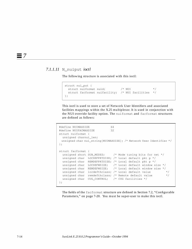
7-14 SunLink X.25 8.0.2 Programmer’s Guide—October 1994
7
7.1.1.11 N_nuiput ioctl
The following structure is associated with this ioctl:
This ioctl is used to store a set of Network User Identifiers and associatedfacilities mappings within the X.25 multiplexor. It is used in conjunction withthe NUI override facility option. The nuiformat and facformat structuresare defined as follows:
The fields of the facformat structure are defined in Section 7.2, “ConfigurableParameters,” on page 7-20. You must be super-user to make this ioctl.
struct nui_put { struct nuiformat nuid; /* NUI */ struct facformat nuifacility; /* NUI facilities */};
#define NUIMAXSIZE 64#define NUIFACMAXSIZE 32struct nuiformat { unsigned charnui_len; unsigned char nui_string[NUIMAXSIZE]; /* Network User Identifier */};
struct facformat { unsigned short SUB_MODES; /* Mode tuning bits for net */ unsigned char LOCDEFPKTSIZE; /* Local default pkt p */ unsigned char REMDEFPKTSIZE; /* Local default pkt p */ unsigned char LOCDEFWSIZE; /* Local default window size */ unsigned char REMDEFWSIZE; /* Local default window size */ unsigned char locdefthclass; /* Local default value */ unsigned char remdefthclass; /* Remote default value */ unsigned char CUG_CONTROL; /* CUG facilities */};

NLI Management ioctls 7-15
7
7.1.1.12 N_nuidel ioctl
The following structure is associated with this ioctl:
This ioctl is used to delete the mapping for a specified Network User Identifier.You must be super-user to make this ioctl.
7.1.1.13 N_nuiget ioctl
The following structure is associated with this ioctl:
This ioctl is used to read the mapping for a specified Network User Identifier. Anon-privileged user can invoke this ioctl.
7.1.1.14 N_nuimget ioctl
The following structure is associated with this ioctl:
This ioctl is used to read all existing mappings for Network User Identifiers.The buf field contains the structure for the returned mapping entries. Thefirst_ent field is used to inform the X.25 multiplexor where to start orrestart the table read. It should initially be set to 0, to indicate starting at the
struct nui_del { struct nuiformat nuid; /* NUI to delete */};
struct nui_get { struct nuiformat nuid; /* NUI to get */ struct facformat nuifacility; /* NUI facilities */};
struct nui_mget { unsigned int first_ent; /* First entry required */ unsigned int last_ent; /* Last entry required */ unsigned int num_ent; /* No of entries required */ char buf[MGET_NBUFSIZE]; /* Data Buffer */};

7-16 SunLink X.25 8.0.2 Programmer’s Guide—October 1994
7
beginning of the table. The num_ent field is used by the X.25 multiplexor toindicate the number of mapping entries returned in the buf field. Thelast_ent is set on return to point past the last entry returned (that is, asubsequent N_nuimget ioctl should have first_ent set to the value returnedhere). A non-privileged user can invoke this ioctl.
7.1.1.15 N_nuireset ioctl
This ioctl is used to delete all existing mappings for Network User Identifiers.You must be super-user to make this ioctl.
7.1.1.16 N_traceon ioctl
The following structure is associated with this ioctl:
This ioctl is used to turn on packet level tracing for a particular link or allconfigured links. If all_links is set, tracing is turned on for all configuredlinks. In this case, the linkids of all links for which tracing was activated willbe returned in the active array. The level field is currently ignored by theX.25 multiplexor, as there is only one tracing level. You must be super-user tomake this ioctl.
Note – You must recompile any programs that use this ioctl when you upgradefrom SunLink X.25 8.0 to 8.0.1, as the MAX_LINKS parameter has changed.
struct trc_regioc { uint8 all_links; /* Trace on all links */ uint8 linkid; /* Link */ uint8 level; /* Level of tracing required */ uint8 active[MAX_LINKS+1]; /* tracing actively on */};

NLI Management ioctls 7-17
7
If tracing is enabled, each incoming and outgoing X.25 packet will be sent upthe stream on which the N_traceon ioctl was made. Each X.25 packet will bepreceded by a trc_ctl structure:
The trc_prim field will always be set to TR_X25_DAT. The trc_mid fieldwill always be set to the module ID of the X.25 multiplexor (200).
7.1.1.17 N_traceoff ioctl
This ioctl is used to cancel a previously issued N_traceon ioctl. You must besuper-user to make this ioctl.
7.1.1.18 N_getnliversion ioctl
The following structure is associated with this ioctl:
/*Types of tracing message*/#define TR_CTL 100 /* Basic */#define TR_LLC2_DAT 101 /* Basic + LLC2 parameters */#define TR_LAPB_DAT TR_CTL /* Basic for now */#define TR_X25_DAT TR_CTL /* Basic for now *//*Format for control part of trace messages*/struct trc_ctl { uint8 trc_prim; /* Trace msg identifier */ uint8 trc_mid; /* Id of protocol module */ uint16 trc_spare; /* for alignment */ uint32 trc_linkid; /* Link Id */ uint8 trc_rcv; /* Message tx or rx */ uint8 trc_spare2[3]; /* for alignment */ uint32 trc_time; /* Time stamp */ uint16 trc_seq; /* Message seq number */};
struct nliformat { unsigned char version; /* NLI version number */};
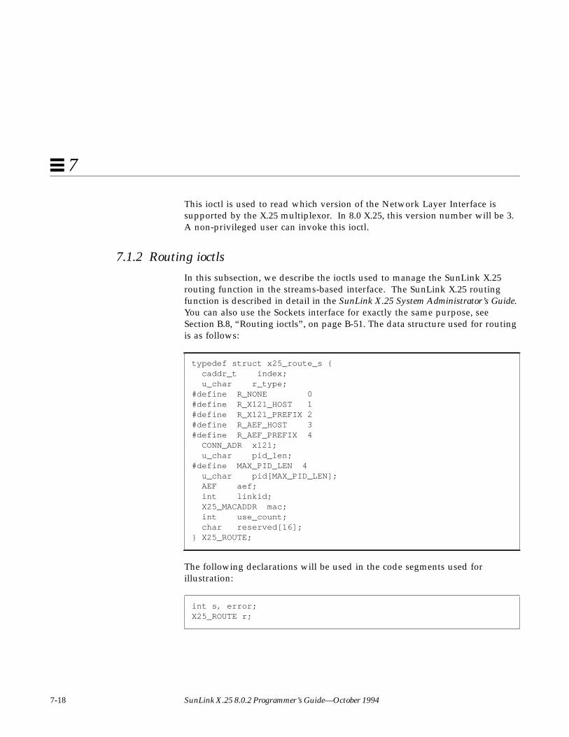
7-18 SunLink X.25 8.0.2 Programmer’s Guide—October 1994
7
This ioctl is used to read which version of the Network Layer Interface issupported by the X.25 multiplexor. In 8.0 X.25, this version number will be 3.A non-privileged user can invoke this ioctl.
7.1.2 Routing ioctls
In this subsection, we describe the ioctls used to manage the SunLink X.25routing function in the streams-based interface. The SunLink X.25 routingfunction is described in detail in the SunLink X.25 System Administrator’s Guide.You can also use the Sockets interface for exactly the same purpose, seeSection B.8, “Routing ioctls”, on page B-51. The data structure used for routingis as follows:
The following declarations will be used in the code segments used forillustration:
typedef struct x25_route_s { caddr_t index; u_char r_type;#define R_NONE 0#define R_X121_HOST 1#define R_X121_PREFIX 2#define R_AEF_HOST 3#define R_AEF_PREFIX 4 CONN_ADR x121; u_char pid_len;#define MAX_PID_LEN 4 u_char pid[MAX_PID_LEN]; AEF aef; int linkid; X25_MACADDR mac; int use_count; char reserved[16];} X25_ROUTE;
int s, error;X25_ROUTE r;

NLI Management ioctls 7-19
7
7.1.2.1 N_X25_ADD_ROUTE ioctl
Sets the fields in the X25_ROUTE structure to the desired values. You must besuperuser to use this ioctl.
7.1.2.2 N_X25_GET_ROUTE ioctl
Obtains the routing information for a given destination address.
7.1.2.3 N_X25_RM_ROUTE ioctl
Removes the route for a given destination address. You must be superuser touse this ioctl.
7.1.2.4 N_X25_FLUSH_ROUTES ioctl
Flushes all routes out. You must be superuser to use this ioctl.
7.1.2.5 N_X25_GET_NEXT_ROUTE ioctl
Obtains routing information for the next entry in the routing table. When thereare no routes left, error will be -1, and errno will be set to ENOENT.

7-20 SunLink X.25 8.0.2 Programmer’s Guide—October 1994
7
7.1.2.6 Routing ioctl Example
The following code segment illustrates the use of the N_X25_ADD_ROUTE ioctl.The other routing ioctls are used in the same way:
7.2 Configurable ParametersConfigurable parameters (for the N_linkconfig ioctl) are defined by thefollowing structure:
#include <sys/strupts.h>struct strioctl ioc ;int fd ;X25_ROUTE r;
fd = open(“/dev/x25”, O,RDW); /*prepare route*/ initialize
io.ic_cmd = N_X25_ADD_ROUTE;io.ic_timeout = 0; /*system default : 15 secs */io.ic_len = sizeof(X25_route);io.ic_dp = (char *)&r;
if (ioctl (fd, I_STR, &ioc) <0) { perror(“ xxxioctl”); }}
Code Example 7-4 wlcfg Structure
struct wlcfg { unsigned long U_LINK_ID; /* Link Identifier */ unsigned char NET_MODE; /* Prot/net in use e.g. X25(84)/LLC */ unsigned char X25_VSN; /* Version 80/84/88 for X.25 */ unsigned char L3PLPMODE; /* Determines the DTE/DCE/DXE mode */
/* X25 PLP virtual circuit ranges */
short LPC; /* Lowest Permanent VC */ short HPC; /* Highest Permanent VC */ short LIC; /* Lowest Incoming channel */ short HIC; /* Highest Incoming channel */
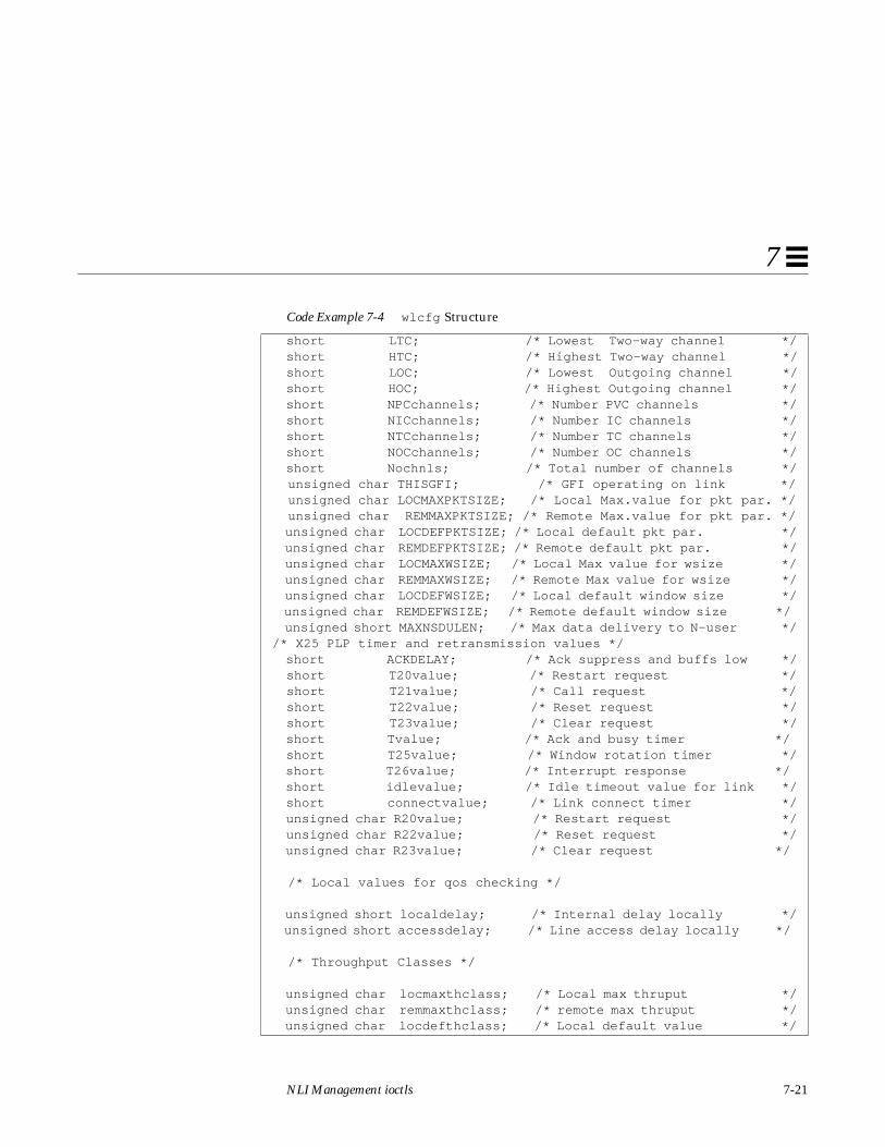
NLI Management ioctls 7-21
7
short LTC; /* Lowest Two-way channel */ short HTC; /* Highest Two-way channel */ short LOC; /* Lowest Outgoing channel */ short HOC; /* Highest Outgoing channel */ short NPCchannels; /* Number PVC channels */ short NICchannels; /* Number IC channels */ short NTCchannels; /* Number TC channels */ short NOCchannels; /* Number OC channels */ short Nochnls; /* Total number of channels */ unsigned char THISGFI; /* GFI operating on link */ unsigned char LOCMAXPKTSIZE; /* Local Max.value for pkt par. */ unsigned char REMMAXPKTSIZE; /* Remote Max.value for pkt par. */ unsigned char LOCDEFPKTSIZE; /* Local default pkt par. */ unsigned char REMDEFPKTSIZE; /* Remote default pkt par. */ unsigned char LOCMAXWSIZE; /* Local Max value for wsize */ unsigned char REMMAXWSIZE; /* Remote Max value for wsize */ unsigned char LOCDEFWSIZE; /* Local default window size */ unsigned char REMDEFWSIZE; /* Remote default window size */ unsigned short MAXNSDULEN; /* Max data delivery to N-user *//* X25 PLP timer and retransmission values */ short ACKDELAY; /* Ack suppress and buffs low */ short T20value; /* Restart request */ short T21value; /* Call request */ short T22value; /* Reset request */ short T23value; /* Clear request */ short Tvalue; /* Ack and busy timer */ short T25value; /* Window rotation timer */ short T26value; /* Interrupt response */ short idlevalue; /* Idle timeout value for link */ short connectvalue; /* Link connect timer */ unsigned char R20value; /* Restart request */ unsigned char R22value; /* Reset request */ unsigned char R23value; /* Clear request */
/* Local values for qos checking */
unsigned short localdelay; /* Internal delay locally */ unsigned short accessdelay; /* Line access delay locally */
/* Throughput Classes */
unsigned char locmaxthclass; /* Local max thruput */ unsigned char remmaxthclass; /* remote max thruput */ unsigned char locdefthclass; /* Local default value */
Code Example 7-4 wlcfg Structure

7-22 SunLink X.25 8.0.2 Programmer’s Guide—October 1994
7
7.2.1 Link Identifier
U_LINK_IDThis is the upper level link identifier which is quoted by upper levelsoftware in the xaddrf address structure (see Section 2.1, “Addresses,” onpage 2-1) to specify which link a call is to be sent on. It is also used toidentify which link an incoming call arrived on. It is selected by the systemadministrator when creating the configuration for the network.
unsigned char remdefthclass; /* Remote default value */ unsigned char locminthclass; /* Local minimum for the PSDN */ unsigned char remminthclass; /* Remote minimum for the PSDN */ unsigned char CUG_CONTROL; /* CUG control */ unsigned short SUB_MODES; /* Link subscription info */
/* PSDN localization record */
struct { unsigned short PSDN_MODES; /* Mode tuning for PSDN */ unsigned char intl_addr_recogn; /* Recognise intnatl */ unsigned char intl_prioritised; /* Prioritise intnatl */ unsigned char dnic1; /* 4 BCD digits DNIC */ unsigned char dnic2; /* Used when required */ unsigned char prty_encode_control; /* Encode priority */ unsigned char prty_pkt_forced_value; /* Force pkt size */ unsigned char src_addr_control; /* Calling addr fixes */ unsigned char dbit_control; /* Action on Dbit */ unsigned char thclass_neg_to_def; /* TELENET negn type */ unsigned char thclass_type; /* Thclass map handle */ unsigned char thclass_wmap[16]; /* Thclass -> wsize */ unsigned char thclass_pmap[16]; /* Thclass -> psize */} psdn_local;
/* Link level local address or local DTE address */
struct lsapformat local_address;};
Code Example 7-4 wlcfg Structure

NLI Management ioctls 7-23
7
7.2.2 Network Mode
NET_MODEThis determines the various characteristics of the network protocol, forexample, a value X25_LLC specifies that X.25 (84) or X.25 (88) over LLC2procedures should be used. Possible values are:
Table 7-1 NET_MODE Mappings
NET_MODE string ValueNetwork, X.25
Type, or Country
X25_LLC 1 (X.25(84/88)/LLC2)
X25_88 2 (X.25(88))
X25_84 3 (X.25(84))
X25_80 4 (X.25(80))
GNS 5 (UK)
AUSTPAC 6 (Australia)
DATAPAC 7 (Canada)
DDN 8 (USA)
TELENET 9 (USA)
TRANSPAC 10 (France)
TYMNET 11 (USA)
DATEX_P 12 (Germany)
DDX_P 13 (Japan)
VENUS_P 14 (Japan)
ACCUNET 15 (USA)
ITAPAC 16 (Italy)
DATAPAK 17 (Sweden)
DATANET 18 (Holland)
DCS 19 (Belgium)
TELEPAC 20 (Switzerland)
F_DATAPAC 21 (Finland)
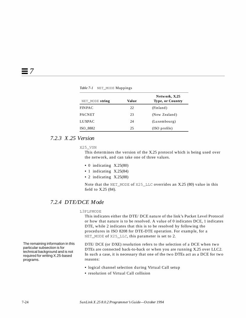
7-24 SunLink X.25 8.0.2 Programmer’s Guide—October 1994
7
7.2.3 X.25 Version
X25_VSNThis determines the version of the X.25 protocol which is being used overthe network, and can take one of three values.
• 0 indicating X.25(80)• 1 indicating X.25(84)• 2 indicating X.25(88)
Note that the NET_MODE of X25_LLC overrides an X.25 (80) value in thisfield to X.25 (84).
7.2.4 DTE/DCE Mode
L3PLPMODEThis indicates either the DTE/DCE nature of the link’s Packet Level Protocolor how that nature is to be resolved. A value of 0 indicates DCE, 1 indicatesDTE, while 2 indicates that this is to be resolved by following theprocedures in ISO 8208 for DTE-DTE operation. For example, for aNET_MODE of X25_LLC, this parameter is set to 2.
DTE/DCE (or DXE) resolution refers to the selection of a DCE when twoDTEs are connected back-to-back or when you are running X.25 over LLC2.In such a case, it is necessary that one of the two DTEs act as a DCE for tworeasons:
• logical channel selection during Virtual Call setup• resolution of Virtual Call collision
FINPAC 22 (Finland)
PACNET 23 (New Zealand)
LUXPAC 24 (Luxembourg)
ISO_8882 25 (ISO profile)
Table 7-1 NET_MODE Mappings
NET_MODE string ValueNetwork, X.25
Type, or Country
The remaining information in thisparticular subsection is fortechnical background and is notrequired for writing X.25-basedprograms.

NLI Management ioctls 7-25
7
The determination of which DTE becomes the DCE occurs when a DTEboots up and goes through the restart procedure (that is, sending a RestartRequest packet, or receiving a Restart Indication packet, whichever comesfirst). There are the following four cases:
• If the DTE sends a Restart Request packet, and gets a confirmation (aRestart Confirmation packet), then it will remain a DTE. This is becauseonly DCEs confirm Restart Request packets.
• If the DTE receives a Restart Indication packet with a cause code otherthan “DTE originated”, then it must have received it from a DCE, so theDTE remains a DTE.
• If the DTE receives a Restart Indication packet with a cause code of “DTEoriginated”, then the DTE will confirm the restart with a RestartConfirmation packet, and will act as the DCE.
• If the DTE had sent a Restart Request packet and before getting aconfirmation, received a Restart Indication with a cause code of “DTEoriginated” (that is, a restart collision), then the DTE will back off and,after a random amount of time, resend a Restart Request to restart theprocedure. In this case, the first DTE to retransmit the Restart Requestwill remain the DTE, because the other DTE will confirm the restart andthereby become the DCE.
The T20 timer determines how long a DTE will wait for a confirmation to aRestart Request. The Connectvalue timer specifies a time limit beforewhich the DTE/DCE resolution phase must be complete, before pendingconnections are aborted. See “Timers” on page 7-28 for a description ofthese timers.
7.2.5 Channel Ranges
LPC to HPC, LIC to HIC , LTC to HTC, LOC to HOCThese specify the ranges of logical channels which are classed as assignedrespectively to permanent virtual circuits, one-way incoming logicalchannels, two-way logical channels, and one-way outgoing logical channels.In a DTE/DTE environment, one of the interacting pairs views these rangesas a DCE, for example, LIC to HIC are viewed as one-way outgoing. Notethat HxC = LxC = 0 denotes no channels in that grouping.
NPCchannels , NICchannels , NTCchannels , NOCchannels and NochnlsThese count the number of logical channels assigned—this is calculatedfrom LIC , HIC , etc. and can be changed only by altering these ranges.
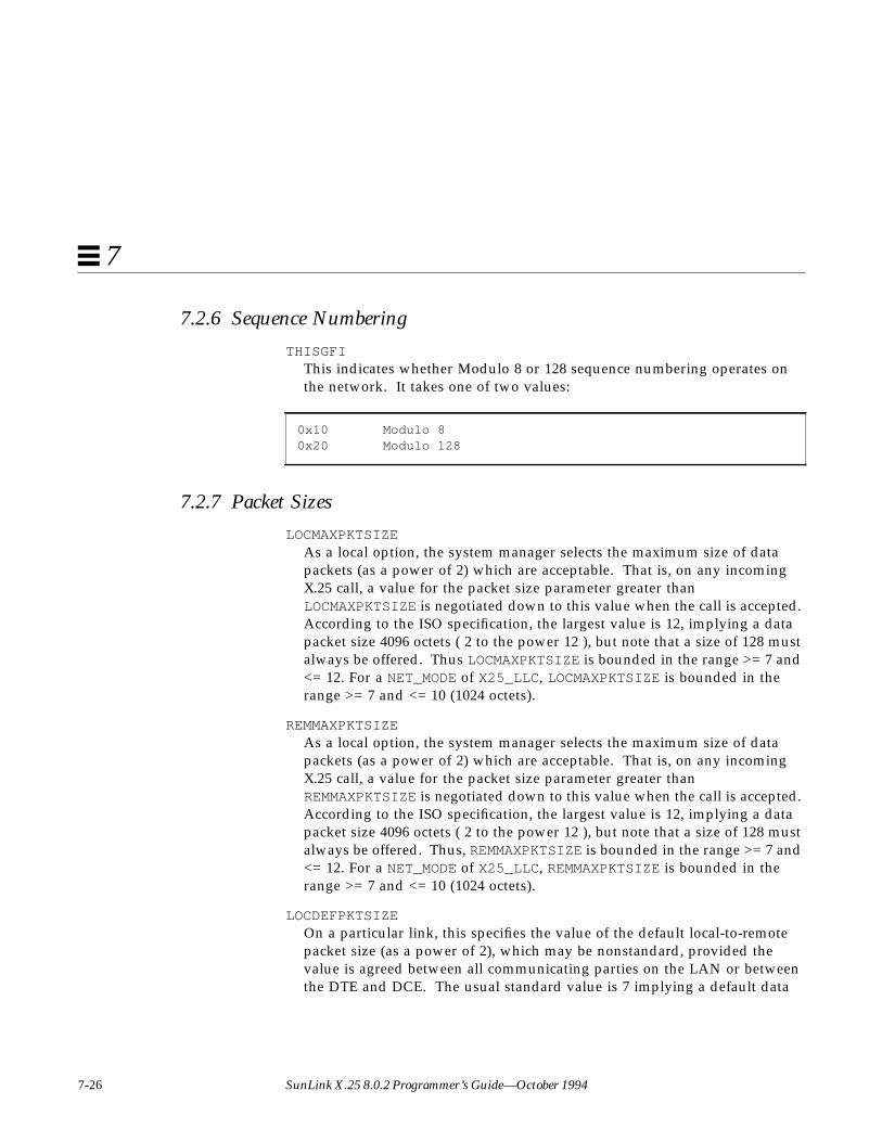
7-26 SunLink X.25 8.0.2 Programmer’s Guide—October 1994
7
7.2.6 Sequence Numbering
THISGFIThis indicates whether Modulo 8 or 128 sequence numbering operates onthe network. It takes one of two values:
7.2.7 Packet Sizes
LOCMAXPKTSIZEAs a local option, the system manager selects the maximum size of datapackets (as a power of 2) which are acceptable. That is, on any incomingX.25 call, a value for the packet size parameter greater thanLOCMAXPKTSIZE is negotiated down to this value when the call is accepted.According to the ISO specification, the largest value is 12, implying a datapacket size 4096 octets ( 2 to the power 12 ), but note that a size of 128 mustalways be offered. Thus LOCMAXPKTSIZE is bounded in the range >= 7 and<= 12. For a NET_MODE of X25_LLC, LOCMAXPKTSIZE is bounded in therange >= 7 and <= 10 (1024 octets).
REMMAXPKTSIZEAs a local option, the system manager selects the maximum size of datapackets (as a power of 2) which are acceptable. That is, on any incomingX.25 call, a value for the packet size parameter greater thanREMMAXPKTSIZE is negotiated down to this value when the call is accepted.According to the ISO specification, the largest value is 12, implying a datapacket size 4096 octets ( 2 to the power 12 ), but note that a size of 128 mustalways be offered. Thus, REMMAXPKTSIZE is bounded in the range >= 7 and<= 12. For a NET_MODE of X25_LLC, REMMAXPKTSIZE is bounded in therange >= 7 and <= 10 (1024 octets).
LOCDEFPKTSIZEOn a particular link, this specifies the value of the default local-to-remotepacket size (as a power of 2), which may be nonstandard, provided thevalue is agreed between all communicating parties on the LAN or betweenthe DTE and DCE. The usual standard value is 7 implying a default data
0x10 Modulo 80x20 Modulo 128
NLI Management ioctls 7-27
7
packet size in the local-to-remote direction of transmission of 128 ( 2 to thepower 7 ) octets. LOCDEFPKTSIZE is bounded in the range >= 4 and <=LOCMAXPKTSIZE.
REMDEFPKTSIZEOn a particular link, this specifies the value of the default remote-to-localpacket size (as a power of 2), which may be nonstandard, provided thevalue is agreed between all communicating parties on the LAN or betweenthe DTE and DCE. The usual standard value is 7 implying a default datapacket size in the remote-to-local direction of transmission of 128 (2 to thepower 7) octets. REMDEFPKTSIZE is bounded in the range >= 4 and <=REMMAXPKTSIZE.
7.2.8 Window Sizes
LOCMAXWSIZEAs a local option, the system manager selects the maximum size of the X.25window which is acceptable. That is, on any incoming X.25 call, a value forthe window size parameter greater than LOCMAXWSIZE is negotiated downto this value when the call is accepted. For Modulo 8 networks,LOCMAXWSIZE is bounded in the range >=2 and <= 7 while for Modulo 128,the range is >=2 and <= 127.
REMMAXWSIZEAs a local option, the system manager selects the maximum size of the X.25window which is acceptable. That is, on any incoming X.25 call, a value forthe window size parameter greater than REMMAXWSIZE is negotiated downto this value when the call is accepted. For Modulo 8 networks,REMMAXWSIZE is bounded in the range >=2 and <= 7 while for Modulo 128,the range is >=2 and <= 127.
LOCDEFWSIZEOn a particular link, this specifies the value of the local-to-remote defaultwindow size, which may be nonstandard provided the value is agreedbetween all communicating parties on the LAN or between the DTE andDCE. The usual standard value is 2. Note that the sequence numberingscheme, Modulo 8 or 128 affects the range of this parameter. LOCDEFWSIZEis bounded in the range >= 1 and <= LOCMAXWSIZE.

7-28 SunLink X.25 8.0.2 Programmer’s Guide—October 1994
7
REMDEFWSIZEOn a particular link, this specifies the value of the remote-to-local defaultwindow size, which may be nonstandard provided the value is agreedbetween all communicating parties on the LAN or between the DTE andDCE. The usual standard value is 2. Note that the sequence numberingscheme, Modulo 8 or 128 affects the range of this parameter. REMDEFWSIZEis bounded in the range >= 1 and <= REMMAXWSIZE.
7.2.9 Maximum NSDU Limit
MAXNSDULENThe X.25 code attempts to concatenate data packets marked with the MoreData Mark (M-bit) into a single network service data unit. However, inorder to protect against buffer exhaustion, the system manager can specify adefault maximum length beyond which concatenation is stopped and thedata currently held is passed to the NS-user (with, of course, the Moreparameter set). This parameter can be overridden on a per-circuit basisusing the nsdulimit parameter on N-CONNECT requests and N-CONNECTresponses.
7.2.10 Timers
ACKDELAYThe X.25 code attempts to suppress the generation of level 3 Receive Ready(RR) packets. Acknowledgement carried by data or multipleacknowledgments is preferred over the case when each data packet isexplicitly and separately acknowledged. Thus, ACKDELAY specifies themaximum delay in ticks (0.1 second units) over which a pendingacknowledgement will be withheld.
Default Value [ 5 ].Permitted Range [ 1 - 32000 ].

NLI Management ioctls 7-29
7
T20valueThis specifies, in number of ticks (0.1 second units), the value of DTE timerparameter T20, the Restart Request Response Timer.
T21valueThis specifies, in number of ticks (0.1 second units), the value of DTE timerparameter T21, the Call Request Response Timer.
T22valueThis specifies, in number of ticks (0.1 second units), the value of DTE timerparameter T22, the Reset Request Response Timer.
T23valueThis specifies, in number of ticks (0.1 second units), the value of DTE timerparameter T23, the Clear Request Response Timer.
TvalueThis field is related, but does not correspond exactly, to the DTE WindowStatus Transmission Timer, T24. It specifies the maximum time interval overwhich acknowledgements of data received from the remote transmitter willbe withheld. Moreover, after expiration of this timer, any withheldacknowledgements will be carried by a Receive Not Ready (RNR) packet.This timer is implemented to ensure that non-receipt of acknowledgement
Default Value [ 1800 ].Permitted Range [ 0 - 32000 ].
Default Value [ 2000 ].Permitted Range [ 0 - 32000 ].
Default Value [ 1800 ].Permitted Range [ 0 - 32000 ].
Default Value [ 1800 ].Permitted Range [ 0 - 32000 ].

7-30 SunLink X.25 8.0.2 Programmer’s Guide—October 1994
7
by the remote transmitter does not cause resets within the virtual circuit. Itshould be emphasized that the implementation of this timer does not implytransmission of window status every Tvalue ticks (0.1 second units).
T25valueThis specifies, in number of ticks (0.1 second units), the value of DTE timerparameter T25, the Window Rotation Timer.
T26valueThis specifies, in number of ticks (0.1 second units), the value of DTE timerparameter T26, the Interrupt Response Timer.
idlevalueThis is the number of ticks (0.1 second units) over which a link-levelconnection associated with no connections is maintained. If the link is to aWAN then this should be set to zero (that is, infinity). This timer is onlymeaningful on a LAN.
Default Value [ 750 ].Permitted Range [ 0 - 32000 ].
Default Value [ 1500 ].Permitted Range [ 0 - 32000 ].
Default Value [ 1800 ].Permitted Range [ 0 - 32000 ].
LAN Default Value [ 600 ].WAN Default Value [ 0 ].Permitted Range [ 0 - 32000 ].

NLI Management ioctls 7-31
7
connectvalueThis specifies the number of ticks (0.1 second units) over which theDTE/DCE resolution phase must be complete. It is implemented in order toprevent the (unlikely) event that the two packet level entities cannot resolvetheir DTE/DCE nature. On expiration of this timer, the link connection isdisconnected and all pending connections aborted.
7.2.11 Counters
R20value , R22value , and R23valueThese specify, respectively, the DTE Restart Request Retransmission Count,the DTE Reset Request Retransmission Count and the DTE Clear RequestRetransmission Count.
7.2.12 Transit Delay
Localdelay and AccessdelayThese are, respectively, in milliseconds, the values of the transit delayattributed to internal processing and the effect of the line transmission rate.These values are used to check whether any maximum acceptable end-to-end transit delay specified in an N-CONNECT request or an N-CONNECTindication is in fact available.
7.2.13 Throughput Classes
LocmaxthclassThis is the maximum value of the throughput class quality of serviceparameter in the local-to-remote direction which is supported. According toISO 8208 this parameter is bounded in the range >=3 and <=12corresponding to a range 75 to 48000 bits/second.
Default Value [ 2000 ].Permitted Range [ 0 - 32000 ].
Default Value [ 1 ].Permitted Range [ 1 - 255 ].
7-32 SunLink X.25 8.0.2 Programmer’s Guide—October 1994
7
RemmaxthclassThis is the maximum value of the throughput class quality of serviceparameter in the remote-to-local direction which is supported. According toISO 8208 this parameter is bounded in the range >=3 and <=12corresponding to a range 75 to 48000 bits/second.
LocdefthclassIn some networks, for example, TELENET, negotiation of throughput classis constrained to be towards a configured default throughput class. In suchcases the flag thclass_neg_to_def (see below) is non-zero andlocdefthclass is the default for the local-to-remote direction. In otherPSDNs, locdefthclass should be set equal to the value oflocmaxthclass (see above).
Note that locmaxthclass >= locdefthclass .
RemdefthclassIn some networks, for example, TELENET, negotiation of throughput classis constrained to be towards a configured default throughput class. In suchcases the flag thclass_neg_to_def (see below) is non-zero andremdefthclass is the default for the remote-to-local direction. In otherPSDNs, remdefthclass should be set equal to the value ofremmaxthclass (see above).
Note that remmaxthclass >= remdefthclass .
LocminthclassAccording to ISO 8208, the throughput class parameter is defined in therange >= 3 and <= 12. Some PSDNs may provide a different mapping, inwhich case locminthclass is the minimum value in the local-to-remotedirection. Note that locmaxthclass >= locdefthclass >=locminthclass .
RemminthclassAccording to ISO 8208, the throughput class parameter is defined in therange >= 3 and <= 12. Some PSDNs may provide a different mapping, inwhich case remminthclass is the minimum value in the remote-to-localdirection. Note that remmaxthclass >= remdefthclass >=remminthclass .
NLI Management ioctls 7-33
7
7.2.14 Closed User Groups
CUG_CONTROLThis field controls Closed User Group actions in two ways. Firstly, itdescribes the type, if any, of Closed User Group facilities subscribed to. Thisis used to choose the appropriate encoding for any closed user groupfacilities in N-CONNECT requests. Secondly, it specifies the action to be takenif the Closed User Group optional facility is present in an incoming call. Itis a bit map where each bit, if set, denotes the following:
Bit 0: subscription to CUGs with no Outgoing or Incoming Access
Bit 1: subscription to Preferential CUG
Bit 2: subscription to CUGs with Outgoing Access
Bit 3: subscription to CUGs with Incoming Access ( For Information Only )
Bit 4: subscription to Basic Format CUGs
Bit 5: subscription to Extended format CUGs
Bit 6: reject incoming calls containing any Closed User Group facility
Bit 7: reserved
In selecting valid subscriptions, it should be noted that bits 0 and 2 aremutually exclusive as are bits 4 and 5.
7.2.15 Subscription Modes
SUB_MODESThis field contains information on the various subscription options for aparticular PSDN link. It is a bit map in which the various entries when setimply:
SUB_EXTENDEDSubscribe to extended call packets.
BAR_EXTENDEDTreat incoming extended call packets as a procedure error.
7-34 SunLink X.25 8.0.2 Programmer’s Guide—October 1994
7
The use of extended call packets allows window and packet sizenegotiation. The SUB_EXTENDED field if set, permits the use of extendedCALL REQUEST and CALL ACCEPT packets. The BAR_EXTENDED field if notset, permits the use of extended INCOMING CALL and CALL CONFIRMpackets.
SUB_FSELECTSubscribe to fast select with no restriction on response.
SUB_FSRRESPSubscribe to fast select with restriction on response.
The SUB_FSELECT field if set permits the use of fast select on INCOMINGCALL packets. The SUB_FSRRESP field if set permits the use of fast selectwith restricted response on INCOMING CALL packets.
SUB_REVCHARGESubscribe to reverse charging.
SUB_LOC_CHG_PREVSubscribe to local charging prevention.
The SUB_REVCHARGE field if set permits the use of reverse charges onINCOMING CALL packets. The SUB_LOC_CHG_PREV field if set has twoeffects. It prevents the use of reverse charges on INCOMING CALL packetsregardless of the setting of SUB_REVCHARGE, and any CALL REQUESTpacket will have the reverse charges facility automatically inserted.
SUB_TOA_NPI_FMTSubscribe to using TOA/NPI address format.
BAR_TOA_NPI_FMTTreat incoming TOA/NPI address formats as a procedure error
The SUB_TOA_NPI_FMT field if set specifies that all call set-up and clearingpackets transmitted will always use the TOA/NPI address format. TheBAR_TOA_NPI_FMT field if set specifies that any call set-up and clearingpackets received employing the TOA/NPI address format will be treated asa procedure error.
SUB_NUI_OVERRIDESubscribe to NUI override.

NLI Management ioctls 7-35
7
The SUB_NUI_OVERRIDE field if set specifies that when an NUI is providedin a CALL REQUEST, then any associated subscription time options overridethe facilities which apply to the interface, for the duration of that particularcall.
BAR_INCALLBar incoming calls.
BAR_OUTCALLBar outgoing calls.
These two fields allow the system administrator to bar access either to orfrom the local machine. The BAR_INCALL field if set disallows INCOMINGCALL packets. The BAR_OUTCALL field if set disallows CALL REQUESTpackets.
7.2.16 PSDN Localization
Some PSDNs require certain procedures to be followed which are not standardfor all X.25 networks. The structure psdn_local contains the flags used totune the actions of the X.25 driver to the requirements of the particularnetwork to which the configuration refers. The entries and values taken bythe psdn_local structure are described below.
PSDN_MODESThis is used to tune the various options for a particular PSDN link. It is a bitmap in which the various entries when set imply:
Table 7-2 PSDN Modes
Mode Description
ACC_NODIAG Allow the omission of the diagnostic byte in incomingRESTART, CLEAR and RESET INDICATION.
USE_DIAG Use diagnostic packets.
CCITT_CLEAR_LEN Restrict the length of a CLEAR INDICATION to 5 bytesand a CLEAR CONFIRM to 3 bytes.
BAR_DIAG Disallow diagnostic packets.

7-36 SunLink X.25 8.0.2 Programmer’s Guide—October 1994
7
The BAR_DIAG and DISC_NZ_DIAG entries specify the treatment of incomingdiagnostic packets. When BAR_DIAG is set, incoming diagnostic packets arehandled as follows. If USE_DIAG is set, and the link is configured as a DCE,then a diagnostic packet is sent to the DTE. Otherwise, the incomingdiagnostic packet is simply discarded. When DISC_NZ_DIAG is set, diagnosticpackets will be discarded when received on non-zero logical channel numbers.If ACC_HEX_ADD is set, DTE addresses are not restricted to containing onlyBCD digits.
7.2.16.1 International Call Address Recognition
Intl_addr_recognThis concerns the means, and whether, outgoing international call requestsare to be recognised. The called DTE address is examined according to thevalue in this field.
The main use of this feature is in conjunction with the intl_prioritisedfield discussed below.
The values and their interpretation are:
0International calls are not distinguished.
1The DNIC of the called DTE address is examined and compared to thatheld in psdn_local members dnic1 and dnic2 . A mismatchimplies an international call.
2International calls are distinguished by having a “1” prefix on the calledDTE address; for example, DATAPAC has this feature.
DISC_NZ_DIAG Discard diagnostic packets on a non-zero LCN.
ACC_HEX_ADD Allow DTE addresses to contain hexadecimal digits.
BAR_NONPRIV_LISTEN Disallow a non-privileged user (that is, one withoutsuperuser privilege) from listening for incoming calls.
Table 7-2 PSDN Modes
Mode Description

NLI Management ioctls 7-37
7
3International calls are distinguished by having a “0” prefix on the calledDTE address.
Dnic1 , dnic2This contains the first four BCD digits of the DNIC and is only used whenintl_addr_recogn has the value one.
7.2.16.2 International Call Prioritization
Intl_prioritisedThis determines whether some prioritization method is to be used forinternational calls (assuming that the PSDN supports such a feature) and isused in conjunction with prty_encode_control andprty_pkt_forced_value .
Intl_prioritised has two values: zero implying no priority, while non-zero implies an attempt to prioritise according to ptry_encode_control .
intl_addr_recogn has the value one.
Prty_encode_controlThis describes how the priority request is to be encoded for this PSDN. Thefollowing values are currently valid:
0The priority is encoded according to section 3.3.3 of Annex G, BlueBook Volume VIII, Fascicle VIII.3 (CCITT, 1988).
1Encode the priority request using the DATAPAC Priority Bit (1976version).
2Encode the priority request using the DATAPAC Traffic Class (1980version which uses the Calling Network facility marker).
Prty_pkt_forced_valueIf this entry is non-zero then it implies that all priority call requests andincoming calls should have the associated packet size parameter forced tothis value (note that the actual packet size is two to the power of thisparameter; for example, 7 implies 128 byte packets). A zero value impliesno special action on packet size is required.

7-38 SunLink X.25 8.0.2 Programmer’s Guide—October 1994
7
7.2.16.3 Calling Address Control
Src_addr_controlThis provides the means to override or set the calling address in outgoingcall requests for this PSDN. It takes the following values:
0No special action. Calling DTE addresses are encoded as and ifprovided by the network service user.
1Force omission of the calling DTE address, even if the network serviceuser supplied one.
2If the network service user does not supply a DTE address, use theconfigured DTE address (local_address ) for this PSDN (which can,of course, be NULL).
3Force the calling DTE address to that contained in local_address ,even if the network service user supplied one.
7.2.16.4 Dbit Operation
Dbit_controlThis field specifies the action to be taken:
• during the call setup phase, where both parties do not agree on the use ofthe D-bit;
• during the data transfer phase, on receipt of a data packet with the D-bitset, where the use of the D-bit has not been agreed by both parties.
Actions which may be specified during the call setup phase are:
• Leave the D-bit set and pass the packet on.• Zero the D-bit and pass the packet on.• Clear the call.
Actions which may be specified during the data transfer phase are:
• Leave the D-bit set and pass the packet on.• Zero the D-bit and pass the packet on.
NLI Management ioctls 7-39
7
• Reset the call.
7.2.16.5 Throughput Class Negotiation
Thclass_neg_to_defThis accommodates certain network procedures which dictate thatnegotiation of throughput class must be towards the default value (forexample, TELENET), the default value being configured into the memberdefthclass . A non-zero value in this field requests use of this option, zeroimplies non-use.
Thclass_typeThis provides the means by which throughput class encodings can be usedto assign window and packet sizes (according to the arrays thclass_wmapand thclass_pmap described below). It should be noted that someimplementations of X.25 do not use the X.25 packet and window negotiationbut instead rely on mapping the throughput class to these parameters (seethclass_type 1,2 and 3). Thclass_type should be used on such PSDNs.Note also that the values of locmaxthclass and remmaxthclass mayhave an effect on what is achieved through the mapping.
The values currently assigned to thclass_type to indicate the mappingare:
0No special action is to be taken on throughput class.
1Use only the low nibble of the throughput class parameter to mapwindow and packet size for both directions and encode the high nibbleas zero. Note that the window and packet sizes are intended to beasserted by the throughput class parameter.
2Use only the high nibble of the throughput class parameter to mapwindow and packet size for both directions and encode the low nibbleas zero. Note that the window and packet sizes are intended to beasserted by the throughput class parameter.

7-40 SunLink X.25 8.0.2 Programmer’s Guide—October 1994
7
3Use both nibbles of the throughput class to map window and packetsize for the appropriate directions. Note that the window and packetsizes are intended to be asserted by the throughput class parameter.
Values 1, 2 and 3 are intended for use on non-standard X.25 PSDNimplementations and it is important to note the following restrictions andadvice.
For the special values 1 and 2 the following items should be noted:
• It is not advisable to select these values when window and packet sizescan appear in call setup packets (that is, subscription to window andpacket size negotiation) since this algorithm is designed for those PSDNswhich support only the mapping procedure.
• In call requests, the network service user should specify equal values forlocthroughput and remthroughput in the qosformat , to ensure thatthe correct behavior is obtained (see also high and low nibble usage forthese two values).
• It should also be noted that, for these values, the user will be barred fromnegotiating window and packet sizes, and the throughput class will not beindicated in a connect indication.
For the value 3, window and packet sizes can be negotiated by the networkservice user only through the throughput class parameter. Negotiationsthrough the flow negotiation parameters when subscribing to the extendedfacility option are overridden. However, as for values 1 and 2, this value isintended only for cases where this is the only means of negotiating windowand packet sizes.
Since window and packet sizes can be mapped using these three valueswithout the use of window and packet negotiation facilities, it is importantthat the map (thclass_wmap and thclass_pmap ) is correct for thePSDN, in order to ensure that both called and calling parties agree on thevalues associated with a particular throughput class.
Thclass_wmap , Thclass_pmapThese are respectively the mapping between the value of the throughputclass (a number 0 to 15) and a window and packet parameter, respectively.An entry zero in this table indicates that the currently set or default value beused.

NLI Management ioctls 7-41
7
7.2.17 Link Address
Local_addressHolds the local DTE address for this X.25 link. It is held in a byte array,local_address.lsap_add , with an associated length bytelocal_address.lsap_len .
7.2.18 Timer Relationships
The above timer defaults are those specified in ISO 8208. The assignment of avalue to T25 requires some comment. The code may be configured to be lenientin the case of flow control inhibition (see Section 11.2 of ISO 8208). That is, adecision has to be made in order to cater for the case when the remote stationdoes not rotate the window fast enough to prevent expiration of T25. ISO 8208recommends strongly that high level protocols be used to effect recovery andthis should be considered. This effect can be achieved by setting T25 to eitherzero (implying infinite) or a very large value.
The timer Tvalue , should be set to a value approximately half the T25 value,in order to prevent the remote PLP from resetting on T25 expiration. The timerACKDELAY should be approximately 0.5 seconds, although thisrecommendation may change after evaluation and experience is gained.
Finally, the idlevalue timer may be set according to how quickly the LANadministration wishes the resource to be reclaimed, while connectvalueshould be about three times the T20 value.
Note also that ISO 8208 recommends that the retry values R20, R22 and R23should never be set to zero in order to cater for the possibility of collisions (seefootnote to Figure 6, ISO 8208).

7-42 SunLink X.25 8.0.2 Programmer’s Guide—October 1994
7
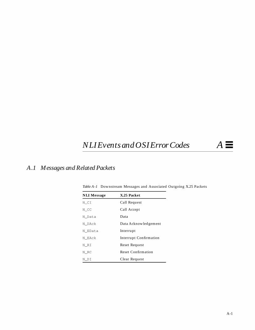
A-1
NLI Events and OSI Error Codes A
A.1 Messages and Related Packets
Table A-1 Downstream Messages and Associated Outgoing X.25 Packets
NLI Message X.25 Packet
N_CI Call Request
N_CC Call Accept
N_Data Data
N_DAck Data Acknowledgement
N_EData Interrupt
N_EAck Interrupt Confirmation
N_RI Reset Request
N_RC Reset Confirmation
N_DI Clear Request
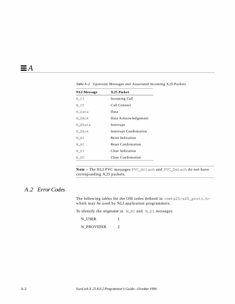
A-2 SunLink X.25 8.0.2 Programmer’s Guide—October 1994
A
Note – The NLI PVC messages PVC_Attach and PVC_Detach do not havecorresponding X.25 packets.
A.2 Error CodesThe following tables list the OSI codes defined in <netx25/x25_proto.h>which may be used by NLI application programmers.
To identify the originator in N_RI and N_DI messages:
N_USER 1
N_PROVIDER 2
Table A-2 Upstream Messages and Associated Incoming X.25 Packets
NLI Message X.25 Packet
N_CI Incoming Call
N_CC Call Connect
N_Data Data
N_DAck Data Acknowledgement
N_EData Interrupt
N_EAck Interrupt Confirmation
N_RI Reset Indication
N_RC Reset Confirmation
N_DI Clear Indication
N_DC Clear Confirmation

NLI Events and OSI Error Codes A-3
A
To specify the reason when the originator is the Network Service provider inN_DI messages:
To specify the reason when the originator is the Network Service user in N_DImessages:
Table A-3 Reason when Originator is NS Provider
Code Value
NS_GENERIC 0xE0
NS_DTRANSIENT 0xE1
NS_DPERMANENT 0xE2
NS_TUNSPECIFIED 0xE3
NS_PUNSPECIFIED 0xE4
NS_QOSNATRANSIENT 0xE5
NS_QOSNAPERMANENT 0xE6
NS_NSAPTUNREACHABLE0xE7
NS_NSAPPUNREACHABLE0xE8
NS_NSAPPUNKNOWN 0xEB
Table A-4 Reason when Originator is NS User
Code Value
NU_GENERIC 0xF0
NU_DNORMAL 0xF1
NU_DABNORMAL 0xF2
NU_DINCOMPUSERDATA 0xF3
NU_TRANSIENT 0xF4
NU_PERMANENT 0xF5
NU_QOSNATRANSIENT 0xF6
NU_QOSNAPERMANENT 0xF7
NU_INCOMPUSERDATA 0xF8
NU_BADPROTID 0xF9

A-4 SunLink X.25 8.0.2 Programmer’s Guide—October 1994
A
To specify the reason when the originator is the Network Service provider inN_RI messages:
NS_RUNSPECIFIED 0xE9
NS_RCONGESTION 0xEA
To specify the reason when the originator is the Network Service user in N_RImessages:
NU_RESYNC 0xFA
Note – These codes are found in ISO 8208 and are mapped from X.25 cause anddiagnostic codes as described in ISO 8878.

B-1
Compatiblity with 7.0—Sockets-based Packet Level Interface B
This chapter describes the sockets-based interface to the SunLink X.25 PacketLayer interface. In the current release, the sockets-based interface has beenreplaced by a streams-based interface. The sockets-based interface issupported for backward-compatibility with SunNet X.25 7.0 only. We stronglyencourage you modify your existing X.25 applications to run over the streams-based interface described in the chapters of this manual.
Note – The sockets-based interface is a source-compatible—not a binary-compatible—interface. Applications that used the socket interface in SunOS4.x must be recompiled to run on SunOS™ 5.x. See Section C.2, “CompilationInstructions and Sample Programs” for instructions on compiling programs touse the sockets-based interface on SunOS 5.x.
8
B.1 Introduction — The AF_X25 DomainThis chapter assumes some familiarity with SunOS sockets and addressdomains (families). Briefly, the socket layer of the network system deals withthe interprocess communications provided by the system. A socket is adescriptor that acts as a bidirectional endpoint for communications and is“typed” by the semantics of the communications it supports. The type of thesocket is defined at socket creation time and used in selecting those serviceswhich are appropriate to support it. The socket type SOCK_STREAM provides

B-2 SunLink X.25 8.0.2 Programmer’s Guide—October 1994
B
sequenced, reliable, two-way, connection-based byte streams with an out-of-band data transmission mechanism. An address domain specifies an addressformat which is used to interpret addresses specified in later operations usingthe socket.
SunLink X.25 defines an address domain, AF_X25. Within this domain only thesocket type SOCK_STREAM is supported. Like other SOCK_STREAM sockets, anAF_X25 domain socket is composed of two byte streams: an in-band streamand an out-of-band stream. However, unlike other sockets, there are twodifferent kinds of out-of-band messages: X.25 status and interrupt data.
B.2 AF_X25 Domain AddressesAddresses in the AF_X25 domain consist of two parts: a DTE address of up to15 BCD digits and Call User Data of up to 16 bytes. (The leading bytes oftheCall User Data is often a protocol identifier [PID] used to identify a specificapplication using X.25.) You can use either subaddressing (part of 15-digitDTE address) or both subaddressing and Call User Data as part of the bindingmechanism to match Incoming Call packets with a server process.
An AF_X25 domain address is described by a CONN_DB structure:
The constants MAXHOSTADR and MAXDATA are defined in the include filex25_pk.h . Currently, MAXHOSTADR is 15, so the length of the host field is 8,and MAXDATA is 102. Use these constants, whenever possible, instead of hard-coded values.
The 15-digit DTE address comprises three components: a Data NetworkIdentification Code (DNIC), a Network Terminal Number (NTN), and asubaddress. A full X.121 address is the concatenation of a DNIC, NTN, andsubaddress, in that order. For example, if the DNIC is 4042, the NTN is 3831,and subaddress is 06, the full X.121 address is 4042383106.
typedef struct conn_db_s {u_char hostlen; /*address length in BCD digits */u_char host[(MAXHOSTADR+1)/2];/* DTE address */u_char datalen; /* user data length in bytes */u_char data[MAXDATA]; /* user data */
} CONN_DB;
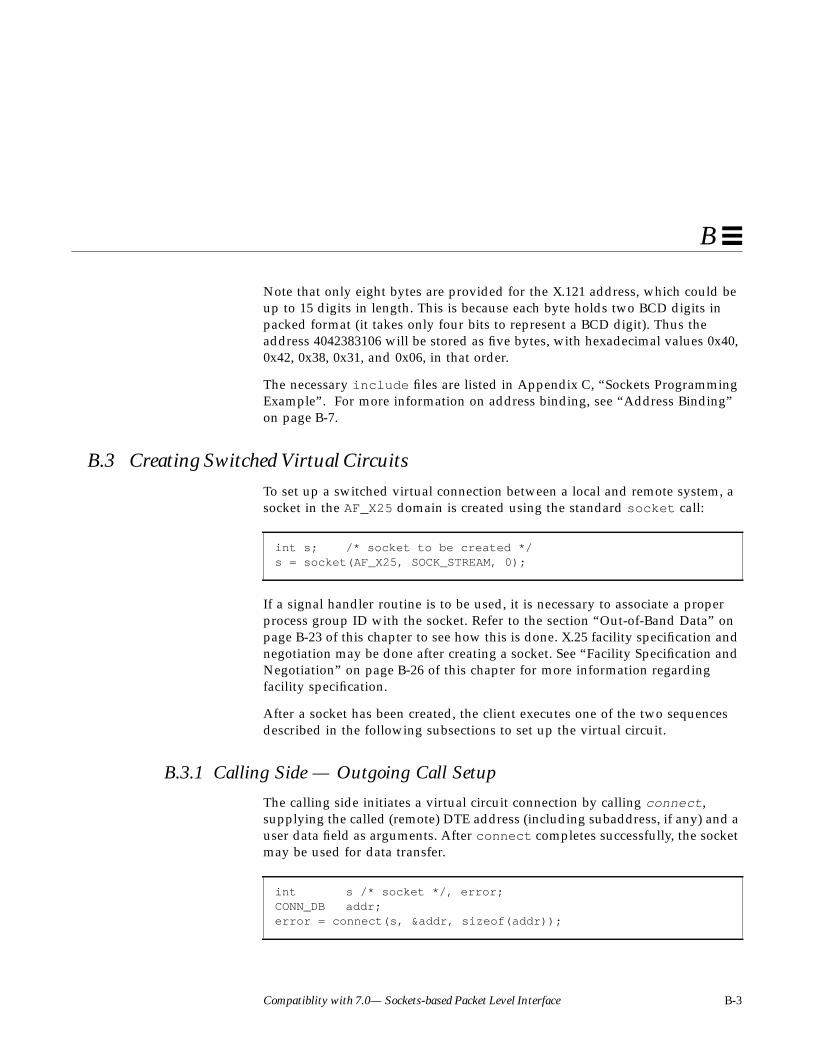
Compatiblity with 7.0— Sockets-based Packet Level Interface B-3
B
Note that only eight bytes are provided for the X.121 address, which could beup to 15 digits in length. This is because each byte holds two BCD digits inpacked format (it takes only four bits to represent a BCD digit). Thus theaddress 4042383106 will be stored as five bytes, with hexadecimal values 0x40,0x42, 0x38, 0x31, and 0x06, in that order.
The necessary include files are listed in Appendix C, “Sockets ProgrammingExample”. For more information on address binding, see “Address Binding”on page B-7.
B.3 Creating Switched Virtual CircuitsTo set up a switched virtual connection between a local and remote system, asocket in the AF_X25 domain is created using the standard socket call:
If a signal handler routine is to be used, it is necessary to associate a properprocess group ID with the socket. Refer to the section “Out-of-Band Data” onpage B-23 of this chapter to see how this is done. X.25 facility specification andnegotiation may be done after creating a socket. See “Facility Specification andNegotiation” on page B-26 of this chapter for more information regardingfacility specification.
After a socket has been created, the client executes one of the two sequencesdescribed in the following subsections to set up the virtual circuit.
B.3.1 Calling Side — Outgoing Call Setup
The calling side initiates a virtual circuit connection by calling connect ,supplying the called (remote) DTE address (including subaddress, if any) and auser data field as arguments. After connect completes successfully, the socketmay be used for data transfer.
int s; /* socket to be created */s = socket(AF_X25, SOCK_STREAM, 0);
int s /* socket */, error;CONN_DB addr;error = connect(s, &addr, sizeof(addr));

B-4 SunLink X.25 8.0.2 Programmer’s Guide—October 1994
B
SunLink X.25supports multiple physical interfaces (or links). A single linkmaps to a serial port device, such as zsh0 .
A link is automatically selected for the outgoing call. Among multiple links,SunLink X.25 routes outgoing calls based on the called address. Calls arerouted according to the full or partial addresses (X.121, or NSAP or non-NSAPextended addresses) you specify in a routes file, the syntax for which isdescribed in the SunLink X.25 8.0.2 Reference Manual. The lowest-numberedlink is the default.
If the interface supports 1984 X.25, the user may also specify a Called AddressExtension Facility (AEF). In this case, SunLink X.25 will use the Called AEF toroute the call over a particular link, provided the user has not specified anX.121 address. If the user wants the call to be routed based on the Called AEF,the hostlen field should be set to zero:
Where AEFs are used for routing, SunLink X.25 will select the interface to useand will also supply the X.121 address (if any) for the Call Request packet. Inaddition, if it is a LAN interface, SunLink X.25 will supply the necessary LSAPaddress.
Called and Calling AEFs are described in the section “Facility Specification andNegotiation” on page B-26.
Note – error is used in most examples to indicate the return code. A value ofzero indicates a successful operation. A non-zero value indicates anunsuccessful operation. The cause of the error is stored in a global variableerrno which is used throughout this manual. Values of errno are enumeratedin <errno.h> . These values are listed in intro(2) in the SunOS ReferenceManual . Programmers may access errno by inserting the following line intheir programs: extern int errno; Note that errno indicates the causeof the very last system call failure and is therefore invalid for operationsreturning an error value of zero. To get more information on the meaning ofthe error string printed, use the perror function.
addr.hostlen = 0;

Compatiblity with 7.0— Sockets-based Packet Level Interface B-5
B
B.3.2 Calling Side — Setting the Local Address
Often, the receiver of an Incoming Call needs to know the address of the callerin order to validate the call. By default, the calling address in the Call Requestis set to the address (including the subaddress, if any) specified in theconfiguration file of the link over which the Call Request is sent. There areseveral parameters in the link configuration file, all described in the precedingsubsection, that determine how SunLink X.25 preprocesses the calling addressto satisfy the requirements of the interface.
You may specify a different address using the X25_WR_LOCAL_ADR ioctl. Theaddress is specified in a CONN_ADR structure.
Here, as in the CONN_DB structure, hostlen is the length of the address inBCD digits, and host contains the address in packed BCD format. TheX25_WR_LOCAL_ADR ioctl call is issued as follows:
The setting of the source address—and whether the X25_WR_LOCAL_ADR ioctlhas effect—is controlled by the setting of the Source Address Controlparameter in the Create/Modify configuration files➤X25 Parameters➤LinkMode Parameters window in x25tool . See the SunLink X.25 8.0.2 ReferenceManual for instructions on setting this parameter.
typedef struct conn_adr_s {u_char hostlen; /* length of BCDs */u_char host[(MAXHOSTADR+1)/2];
} CONN_ADR;
CONN_ADR addr;int s, error;error = ioctl(s, X25_WR_LOCAL_ADR, &addr);
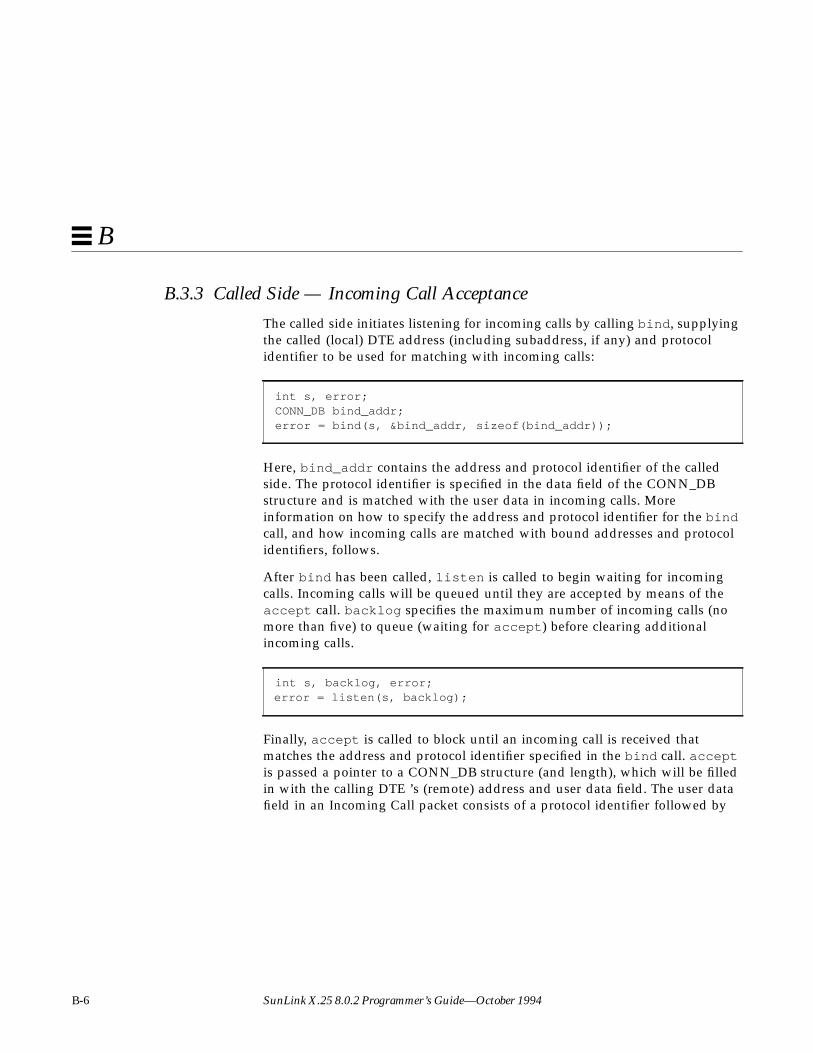
B-6 SunLink X.25 8.0.2 Programmer’s Guide—October 1994
B
B.3.3 Called Side — Incoming Call Acceptance
The called side initiates listening for incoming calls by calling bind , supplyingthe called (local) DTE address (including subaddress, if any) and protocolidentifier to be used for matching with incoming calls:
Here, bind_addr contains the address and protocol identifier of the calledside. The protocol identifier is specified in the data field of the CONN_DBstructure and is matched with the user data in incoming calls. Moreinformation on how to specify the address and protocol identifier for the bindcall, and how incoming calls are matched with bound addresses and protocolidentifiers, follows.
After bind has been called, listen is called to begin waiting for incomingcalls. Incoming calls will be queued until they are accepted by means of theaccept call. backlog specifies the maximum number of incoming calls (nomore than five) to queue (waiting for accept ) before clearing additionalincoming calls.
Finally, accept is called to block until an incoming call is received thatmatches the address and protocol identifier specified in the bind call. acceptis passed a pointer to a CONN_DB structure (and length), which will be filledin with the calling DTE ’s (remote) address and user data field. The user datafield in an Incoming Call packet consists of a protocol identifier followed by
int s, error;CONN_DB bind_addr;error = bind(s, &bind_addr, sizeof(bind_addr));
int s, backlog, error;error = listen(s, backlog);

Compatiblity with 7.0— Sockets-based Packet Level Interface B-7
B
any additional user data. After an incoming call matches the binding criteria,accept returns the socket news, to be used for data transfer. news inherits theprocess group ID from s .
The remote address returned in from will be exactly as received (that is, inexactly the same form as received in the calling address field in the IncomingCall packet).
Note that on entry into the accept call, from_addr_len should be set to thesize of the CONN_DB structure. On return, it will be set to the length of theactual address returned in from .
A typical caller of accept would be a server process that forks a new process(after calling accept ) to handle each new socket. The sample programs (seeAppendix C, “Sockets Programming Example”) provided with SunLink X.25illustrate how this can be done.
B.3.4 Address Binding
When an Incoming Call packet is received by SunLink X.25, the called addressand user data field are matched against all listening sockets. In addition, if theinterface supports 1984 X.25, and if the listener has specified a value for theCalled AEF, the Called AEF field in the Incoming Call (if any) will be matchedwith the Called AEF specified by the listener. If a match is found, the call isaccepted and the user process associated with that socket will be notified whenthe user process does an accept . This permits incoming calls to be bound tothe correct user process. X.25 supports binding by either address or by bothaddress and protocol identifier. The method used is determined by the fields ofthe CONN_DB structure passed to bind .
The address a socket is bound to is specified in the host field of the CONN_DBparameter passed to the bind call. The address is specified in packed BCDformat, and the hostlen field contains the length of the address in BCDdigits.
int s, news;int from_addr_len;CONN_DB from;from_addr_len = sizeof(from);news = accept(s, &from, &from_addr_len);

B-8 SunLink X.25 8.0.2 Programmer’s Guide—October 1994
B
You can specify the bound address in a number of ways, depending onwhether you want to accept all calls (from any link, for any subaddress), or allcalls for a specific subaddress (from any link, for a particular subaddress), orcalls from a specific link for any subaddress, or calls for a specific address(from a specific link, for a specific subaddress).
If you want to accept all calls (from any link, for any subaddress), set the bitsANY_LINK (0x80) and ANY_SUBADDRESS (0x40) in the hostlen field and donot specify any address:
If you want to accept calls from any link, but only for a specific subaddress,specify only the subaddress, and set the ANY_LINK bit in the hostlen field:
If you want to accept calls from a specific link, but for any subaddress, specifythe link address (without the subaddress) and set the ANY_SUBADDRESS bit inthe hostlen field:
If you want to accept calls for a specific address (including subaddress) specifythe exact address in the CONN_DB structure passed to bind . In this case, theaddress you specify must exactly match the called address field of the receivedIncoming Call packet. The address of a link may be obtained with anX25_RD_LINKADR ioctl call (see the section “Accessing the Link (X.25)Address” on page B-46 of this chapter for details).
The sample programs provided with SunLink X.25 illustrate the abovefeatures.
bind_addr.hostlen = ANY_LINK | ANY_SUBADDRESS;
bind_addr.hostlen |= ANY_LINK;
bind_addr.hostlen |= ANY_SUBADDRESS;

Compatiblity with 7.0— Sockets-based Packet Level Interface B-9
B
B.3.5 Binding by PID/CUDF
To bind by protocol identifier (PID), you must specify a protocol identifier inthe data field of the CONN_DB parameter passed to bind . The datalen fieldcontains the length of the protocol identifier. You can specify up to 102 bytes ofprotocol identifier, but only the first 16 bytes will be used for matching withuser data in Incoming Call packets.
The user data field in an Incoming Call may be longer than the protocolidentifier specified in bind . The match will be considered successful if theprotocol identifier specified in bind is an initial sub-string of the user data inan Incoming Call. Thus, if you specify a zero-length protocol identifier inbind , it will match the user data in any Incoming Call.
You can enforce exact matching of the protocol identifier with user data inIncoming Call packets by setting the bit EXACT_MATCH (0x80) in datalen :
In this case, user data in an Incoming Call packet should match the protocolidentifier specified in bind exactly (in content and length) in order for thematch to be considered successful.
See Appendix C, “Sockets Programming Example,” for references to samplecode. A simple example is given below:
bind_addr.datalen |= EXACT_MATCH;
CONN_DB bind_addr;int s, error;/*We want to accept calls from any link, for the subaddress 01.* We must specify the two digit subaddress 01 and set the ANY_LINK* bit in the hostlen field.*/bind_addr.hostlen = 2 | ANY_LINK;/* there are 2 BCD digits */bind_addr.host[0] = 0x01;/* We will specify a protocol identifier consisting of a singlebyte* with value 0x02.*/bind_addr.datalen = 1;bind_addr.data[0] = 0x02;error = bind(s, &bind_addr, sizeof(bind_addr));
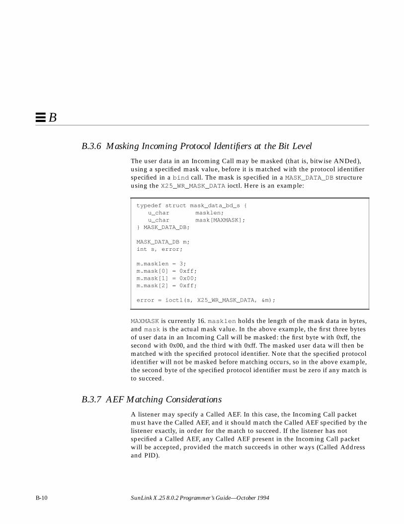
B-10 SunLink X.25 8.0.2 Programmer’s Guide—October 1994
B
B.3.6 Masking Incoming Protocol Identifiers at the Bit Level
The user data in an Incoming Call may be masked (that is, bitwise ANDed),using a specified mask value, before it is matched with the protocol identifierspecified in a bind call. The mask is specified in a MASK_DATA_DB structureusing the X25_WR_MASK_DATA ioctl. Here is an example:
MAXMASK is currently 16. masklen holds the length of the mask data in bytes,and mask is the actual mask value. In the above example, the first three bytesof user data in an Incoming Call will be masked: the first byte with 0xff, thesecond with 0x00, and the third with 0xff. The masked user data will then bematched with the specified protocol identifier. Note that the specified protocolidentifier will not be masked before matching occurs, so in the above example,the second byte of the specified protocol identifier must be zero if any match isto succeed.
B.3.7 AEF Matching Considerations
A listener may specify a Called AEF. In this case, the Incoming Call packetmust have the Called AEF, and it should match the Called AEF specified by thelistener exactly, in order for the match to succeed. If the listener has notspecified a Called AEF, any Called AEF present in the Incoming Call packetwill be accepted, provided the match succeeds in other ways (Called Addressand PID).
typedef struct mask_data_bd_s {u_char masklen;u_char mask[MAXMASK];
} MASK_DATA_DB;
MASK_DATA_DB m;int s, error;
m.masklen = 3;m.mask[0] = 0xff;m.mask[1] = 0x00;m.mask[2] = 0xff;
error = ioctl(s, X25_WR_MASK_DATA, &m);
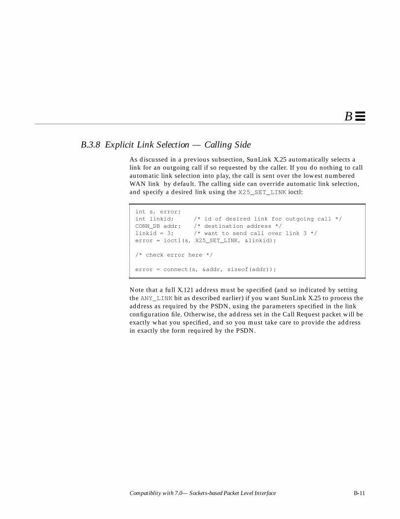
Compatiblity with 7.0— Sockets-based Packet Level Interface B-11
B
B.3.8 Explicit Link Selection — Calling Side
As discussed in a previous subsection, SunLink X.25 automatically selects alink for an outgoing call if so requested by the caller. If you do nothing to callautomatic link selection into play, the call is sent over the lowest numberedWAN link by default. The calling side can override automatic link selection,and specify a desired link using the X25_SET_LINK ioctl:
Note that a full X.121 address must be specified (and so indicated by settingthe ANY_LINK bit as described earlier) if you want SunLink X.25 to process theaddress as required by the PSDN, using the parameters specified in the linkconfiguration file. Otherwise, the address set in the Call Request packet will beexactly what you specified, and so you must take care to provide the addressin exactly the form required by the PSDN.
int s, error;int linkid; /* id of desired link for outgoing call */CONN_DB addr; /* destination address */linkid = 3; /* want to send call over link 3 */error = ioctl(s, X25_SET_LINK, &linkid);
/* check error here */
error = connect(s, &addr, sizeof(addr));

B-12 SunLink X.25 8.0.2 Programmer’s Guide—October 1994
B
Since setting the link prevents SunLink X.25 from consulting the routing table,all the information required to establish connection with the remote user mustbe provided. For example, if the link selected supports 1984 X.25, Called andCalling AEFs may be required. If the link selected is a LAN interface, the LSAPaddress of the remote user must be provided. This is done as follows:
If the lsel field is set to zero, SunLink X.25 will use the value specified in thelink configuration file. After connection is established, the LSAP address of theremote user can be read using the X25_RD_MACADDR command:
typedef struct {u_char lsel;u_char maclen;
#define MACADDR_LEN6u_char macaddr[MACADDR_LEN];
} X25_MACADDR;
X25_MACADDR dst_mac; /* LSAP address */ints; /* socket */
/* set the lsel, maclen and macaddr fields here */
error = ioctl(s, X25_WR_MACADDR, &dst_mac);
X25_MACADDR dst_mac; /* LSAP address */int s; /*socket */
error = ioctl(s, X25_RD_MACADDR, &dst_mac);

Compatiblity with 7.0— Sockets-based Packet Level Interface B-13
B
B.3.9 Explicit Link Selection — Called Side
The called side may restrict the calls it wishes to examine for a possible matchto a particular link by means of the X25_SET_LINK ioctl.
The ANY_SUBADDRESS and ANY_LINK bits can still be used in the same way asexplained in the section“Address Binding” on page B-7 of this chapter. TheANY_LINK bit, in this context, serves as an abbreviation for the link address,and you do not have to specify the link address explicitly. A zero-lengthaddress also works in the same way as described in the “Address Bindingsection. Otherwise, you must specify the address in exactly the form it will bereceived. That is, it must exactly match the called address field of the receivedIncoming Call packet.
int s, linkid, error;CONN_DB addr; /* address and protocol identifier */
linkid = 2; /* restrict calls to link 2 */error = ioctl(s, X25_SET_LINK, &linkid);
/* check error here */
error = bind(s, &addr, sizeof(addr));

B-14 SunLink X.25 8.0.2 Programmer’s Guide—October 1994
B
B.3.10 Accessing the Local and Remote Addresses
Once a connection is established, the calling and called sides may use thegetsockname and getpeername calls to obtain the local and remote X.121addresses:
The local and remote addresses can also be obtained using theX25_RD_LOCAL_ADR and X25_RD_REMOTE_ADR ioctl calls:
Note that for getsockname and getpeername , the CONN_DB structure isused, and for the ioctl calls, the CONN_ADR structure is used. In both cases, thehost field will contain the address in packed BCD format, and the hostlenfield will contain the address length in BCD digits.
int s, error;CONN_DB local; /* local address */int local_len; /* local address length */CONN_DB remote; /* remote address */int remote_len; /* remote address length */
/* get local address */local_len = sizeof(local);error = getsockname(s, &local, &local_len);
/* get remote address */remote_len = sizeof(remote);error = getpeername(s, &remote, &remote_len);
int s, error;CONN_ADR local; /* local address */CONN_ADR remote; /* remote address */
/* get local address */error = ioctl(s, X25_RD_LOCAL_ADR, &local);
/* get remote address */error = ioctl(s, X25_RD_REMOTE_ADR, &remote);

Compatiblity with 7.0— Sockets-based Packet Level Interface B-15
B
For the called side, the remote address will be defined only after theconnection is complete. The remote address obtained using either of the abovetwo methods will be exactly as obtained from the Incoming Call packet. Afterthe call is established, the local address (obtained by either method) will beexactly as received in the called address field in the Incoming Call packet.
For the calling side, the remote address will be exactly as specified in theconnect call. If the ANY_LINK bit was set in the hostlen field, it will be alsoset when it is read by the user using either of the above methods. The sourceaddress for the calling side will be either a zero-length address (indicating thatthe appropriate link address was used), or exactly what the user specifiedusing the X25_WR_LOCAL_ADR ioctl call (including the SUBADR_ONLY bit if itis used).
B.3.11 Finding the Link Used for a Virtual Circuit
If you let SunLink X.25 select the link for an outgoing call, or make an acceptcall that accepts incoming calls from any link, you may use theX25_GET_LINK ioctl to obtain the identifier of the link used for the call:
If this call is made before connection establishment and you have not explicitlyselected a link, linkid will be set to -1 on return from the call. Afterconnection establishment, linkid will have a value in the range zero throughone less than the maximum number of links configured.
An important use for this ioctl arises when the called side determines theremote address in order to call back the remote DTE. In this situation, theremote address is presented in exactly the form it arrived in the Call Request.For some PSDNs, this may not contain a DNIC. Hence, the only way you cancall the remote DTE back is by finding out the link id for the call using theX25_GET_LINK ioctl, and explicitly selecting this link using theX25_SET_LINK ioctl when calling the remote DTE back. In this situation, youshould not set the ANY_LINK bit in the hostlen field of the CONN_DBparameter to the connect call.
int s, error;int linkid; /* link identifier */
error = ioctl(s, X25_GET_LINK, &linkid);

B-16 SunLink X.25 8.0.2 Programmer’s Guide—October 1994
B
B.3.12 Determining the Logical Channel Number for a Connection
To find out which logical channel is associated with a connection, do thefollowing:
Here, s is the socket associated with the connection (or virtual circuit). Onreturn from the call, lcn is set to the logical channel number associated withsocket s . If the returned value of lcn is 0, there is no connected virtual circuitassociated with the socket.
B.4 Sending DataThe send call is used to send data over a virtual circuit. send is passed thesocket, a pointer to the data to be transmitted, the length of the data, and a flagindicating the type of data to be sent. Interrupt data is sent by setting flags toMSG_OOB. Otherwise, flags should be set to zero. The returned countindicates the number of bytes transmitted by send .
Note that for normal data, you can use the write system call instead of send .The call:
is equivalent to:
int s, lcn;error = ioctl(s, X25_RD_LCGN, &lcn);
int count, len, flags, s;char *msg;count = send(s, msg, len, flags);
write(s, msg, len)
send(s, msg, len, 0)

Compatiblity with 7.0— Sockets-based Packet Level Interface B-17
B
The X.25 protocol has the concept of an X.25 message. A complete X.25 messageis a sequence of one or more packets with the M-bit (More bit) set in all but thefinal packet. Normally, X.25 sends the data specified in a send call as acomplete message. This means that the data will be segmented into packets asrequired by the PSDN, and the M-bit will be set in all but the final packet. Ifthe user wishes to pass the data in a complete X.25 message in pieces (that is,using multiple send calls), the setting of the M-bit must be controlled usingthe X25_SEND_TYPE ioctl as described below.
Note – In the current release of SunLink X.25, send() returns a positive resultafter a virtual circuit is closed at the remote end. This behavior is differentfrom 7.0 SunNet X.25. To be notified when the virtual circuit has been closed,use the X25_OOB_ON_CLEAR ioctl, as described in Section B.7.8, “Accessing theDiagnostic Code,” on page B-48.
B.4.1 Control of the M-, D-, and Q-bits
The settings of M-, D- and Q-bits in transmitted packets are changed by meansof the X25_SEND_TYPE ioctl call.
send_type provides the new settings of the M-, D-, and Q-bits. The M-, D-,and Q-bits are encoded into the send_type field by bit shifting as shownbelow.
ints, send_type;error = ioctl(s, X25_SEND_TYPE, &send_type);
#define M_BIT 0 /* number of bits to shift to set "more" * bit */
#define D_BIT 2 /* number of bits to shift to set end-to-end * acknowledge bit */
#define Q_BIT 3 /* number of bits to shift to set qualified * data bit */

B-18 SunLink X.25 8.0.2 Programmer’s Guide—October 1994
B
For example, to set the Q-bit in a packet:
M_BIT determines whether or not a packet is the final piece of a complete X.25message. If M_BIT is set, subsequent send calls are treated as part of a singleX.25 message. If M_BIT is not set, the next send ends the current X.25 message.For example, the following code allows a complete X.25 message to be sent inthree pieces:
If the M-bit is turned on using the X25_SEND_TYPE ioctl, it will stay turned onuntil it is turned off. The X.25 recommendation states that the M-bit shall beturned on only in packets that are “full”—that is, packets that have themaximum size for that virtual circuit. So if the M-bit is turned on, and the nextsend does not supply a full X.25 packet, X.25 will wait until enough send callshave been issued to build a full X.25 packet before transmitting the next packetwith the M-bit turned on.
The Q-bit qualifies the data in Data packets. A local DTE sets the Q-bit toindicate that the data being sent is significant for a device connected to theremote DTE. It is often used by a remote host when sending control packets toa PAD, to distinguish the control packets from packets containing user data.
The D-bit allows a local DTE to specify end-to-end acknowlegement of datapackets. Normally, a DTE receives acknowledgement only from its local DCE.The D-bit is significant only in call setup and data packets.
intsend_type = (1 << Q_BIT), s;error = ioctl(s, X25_SEND_TYPE, &send_type);
ints, send_type, error;/* Set M_BIT to indicate multiple pieces */send_type = (1 << M_BIT);error = ioctl(s, X25_SEND_TYPE, &send_type);/* send first piece */error = send(s, &first_piece, sizeof(first_piece), 0);/* send next piece */error = send(s, &second_piece, sizeof(second_piece), 0);/* Clear M_BIT to indicate end of message */send_type = 0;error = ioctl(s, X25_SEND_TYPE, &send_type);/* send final piece */error = send(s, &final_piece, sizeof(final_piece), 0);

Compatiblity with 7.0— Sockets-based Packet Level Interface B-19
B
D_BIT and Q_BIT control the settings of those bits in an X.25 packet. Thesebits are manipulated in the same manner as the M_BIT was above. Since theX.25 recommendation states that the D_BIT and Q_BIT bits should remainconstant for each packet in a complete X.25 message, D_BIT and Q_BIT shouldonly be changed at the beginning of an X.25 message.
Unlike M_BIT, D_BIT and Q_BIT are turned off automatically after a completeX.25 message has been sent. Hence, to set these bits in a series of complete X.25messages, you should turn them on at the start of each complete X.25 message.If the complete X.25 message is a sequence of full packets with the more bitturned on in all but the last packet in the sequence, the setting of D_BIT andQ_BIT will be the same for all the packets unless you explicitly change thesetting in between.
B.4.2 Sending Interrupt and Reset Packets
An interrupt packet may be sent in the following manner. The interrupt userdata is contained in intr:
If the link supports 1984 X.25, you may send up to 32 bytes of interrupt data.On 1980 links, you may send only one byte.
A reset packet may be sent in the following manner:
This will cause a Reset to be sent with the cause code and diagnostic specifiedby the user. See “Accessing the Diagnostic Code” on page B-48 of this chapterfor more information.
int s;char intr = 0; /* set this variable to contain the interrupt
* user data (in this case 0) */error = send(s, &intr, 1, MSG_OOB);
X25_CAUSE_DIAG diag;int error, s;diag.flags = 0;diag.datalen = 2;diag.data[0] = 0; /* cause */diag.data[1] = 67; /* diagnostic */error = ioctl(s, X25_WR_CAUSE_DIAG, &diag);

B-20 SunLink X.25 8.0.2 Programmer’s Guide—October 1994
B
B.5 Receiving DataTo read data from an X.25 socket, call recv . Data may be either in-band(normal data) or out-of-band (interrupt data and status). To receive out-of-band data, set flags to MSG_OOB. To receive normal data, set flags to 0.
Note that for normal data, you can use the read system call instead of recv .The call:
is equivalent to:
B.5.1 In-Band Data
Calling recv with flags set to zero reads in-band data. Normally, each recvreturns one complete X.25 message. It is very important to note that if the sizeof the receive buffer is not sufficient to hold the entire X.25 message, the excessis discarded and no error indication is returned. This is a feature of SunOSsockets, not of SunLink X.25. count returns a count of the number of bytesreturned by recv. If the user wishes to read an X.25 message in pieces smallerthan a complete message, the X25_RECORD_SIZE ioctl should be used asdescribed in the section “Receiving X.25 Messages in Records” on page B-22 ofthis chapter.
Unless non-blocking I/O has been requested, the recv call will block unlessthere is some data that can be returned to the user. If the connection is cleared(due to normal or abnormal reasons) while recv is blocked, recv will return acount of zero. A return value of zero from recv is an indication that theconnection has been cleared, and the user must close the socket at this point.
int s, len, flags, count;char *buf;count = recv(s, buf, len, flags);
read(s, buf, len)
recv(s, buf, len, 0)
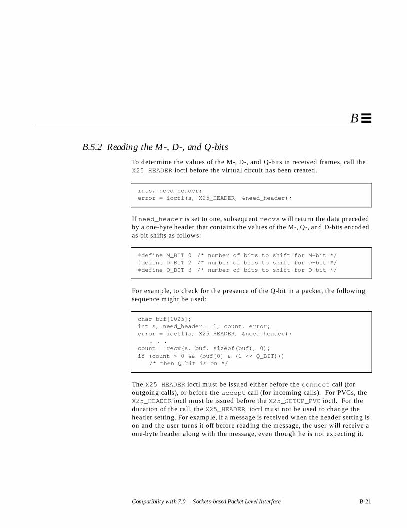
Compatiblity with 7.0— Sockets-based Packet Level Interface B-21
B
B.5.2 Reading the M-, D-, and Q-bits
To determine the values of the M-, D-, and Q-bits in received frames, call theX25_HEADER ioctl before the virtual circuit has been created.
If need_header is set to one, subsequent recvs will return the data precededby a one-byte header that contains the values of the M-, Q-, and D-bits encodedas bit shifts as follows:
For example, to check for the presence of the Q-bit in a packet, the followingsequence might be used:
The X25_HEADER ioctl must be issued either before the connect call (foroutgoing calls), or before the accept call (for incoming calls). For PVCs, theX25_HEADER ioctl must be issued before the X25_SETUP_PVC ioctl. For theduration of the call, the X25_HEADER ioctl must not be used to change theheader setting. For example, if a message is received when the header setting ison and the user turns it off before reading the message, the user will receive aone-byte header along with the message, even though he is not expecting it.
ints, need_header;error = ioctl(s, X25_HEADER, &need_header);
#define M_BIT 0 /* number of bits to shift for M-bit */#define D_BIT 2 /* number of bits to shift for D-bit */#define Q_BIT 3 /* number of bits to shift for Q-bit */
char buf[1025];int s, need_header = 1, count, error;error = ioctl(s, X25_HEADER, &need_header);
. . .count = recv(s, buf, sizeof(buf), 0);if (count > 0 && (buf[0] & (1 << Q_BIT)))
/* then Q bit is on */

B-22 SunLink X.25 8.0.2 Programmer’s Guide—October 1994
B
If the header is requested, X.25 does not wait for a complete X.25 message to beassembled before returning any data to the user. Rather, partial messages(indicated by the presence of M_BIT) are returned to the user as they becomeavailable. Note that the buffer supplied in the recv call must be large enoughto accommodate the extra byte of header information.
B.5.3 Receiving X.25 Messages in Records
By default, each recv returns a complete X.25 message. To force recv toreturn data before a complete X.25 message has been assembled, issue theX25_RECORD_SIZE ioctl after the socket is created:
Here, record_size specifies the number of full (maximum size) packets withM-bit turned on that X.25 will receive before the accumulated data is returnedto the user as a record (or message). Thus, the maximum record size seen bythe user will be record_size times the maximum packet size for the virtualcircuit. If a complete X.25 message comprises less than record_size packets,it will be returned to the user as in the normal case.
The X25_RECORD_SIZE ioctl is useful when complete X.25 messages arepotentially very long, so that either they cannot be buffered in the socketreceive buffers (limited by the high water mark), or it is too much of aperformance bottleneck for the application to wait for the whole message to beassembled before processing it, or the application does not wish to dedicatevery large buffers for receiving data. If record boundaries (that is, messageboundaries) are important, this method must not be used. Rather, theX25_HEADER ioctl must be used, as indicated earlier, to obtain a header bytefor each packet that indicates whether or not the packet is the last one in arecord (that is, message).
int s, record_size, error;/* Set record_size to n, where n is the number of * maximum size packets with more bit turned on that * will be received before the accumulated data is * returned in a recv call. */error = ioctl(s, X25_RECORD_SIZE, &record_size);

Compatiblity with 7.0— Sockets-based Packet Level Interface B-23
B
B.5.4 Out-of-Band Data
Out-of-band data is managed by a combination of ioctl calls, the passing of theMSG_OOB flag to recv , and an optional signal, SIGURG. To determine whetherout-of-band data has been received, call the X25_OOB_TYPE ioctl:
If out-of-band data does not exist, oob_type is set to zero. Otherwise,oob_type is set to a value indicating the type of out-of-band data that hasbeen received. The types of out-of-band data are:
INT_DATA indicates that interrupt data has been received. The interrupt data isread by calling recv with flags set to MSG_OOB. In general, the followingsequence occurs upon receipt of an interrupt packet:
1. X.25 receives an interrupt request packet. The interrupt is queued andcauses a SIGURG signal.
2. The user reads the interrupt packet (with recv ), automatically causing anInterrupt Confirmation packet to be sent.
Up to 32 bytes of interrupt data may be received if the interface supports 1984X.25.
It is not necessary to issue a recv call with flags set to MSG_OOB if theinterrupt type is something other than INT_DATA.
VC_RESET indicates that the virtual circuit associated with the socket has beenreset.
The 7.0 SunLink X.25 interface had an additional type of out-of-band data,MSG_TOO_LONG, which indicated that a message was discarded because of thesocket buffer limitations. This type of out-of-band data does not exist in thecurrent release, because an X.25 message will not get discarded when it getstoo long. “Too long” means that too many packets are received with the M-bitset to 1 and the user has not asked for individual packets with the
ints, oob_type;error = ioctl(s, X25_OOB_TYPE, &oob_type);
#define INT_DATA 30 /* interrupt data */#define VC_RESET 32 /* virtual circuit reset */

B-24 SunLink X.25 8.0.2 Programmer’s Guide—October 1994
B
X25_HEADER ioctl. Instead of getting discarded, the X.25 message will be sentuptstream as soon as its length goes over MAXNSDULEN, whether or not the endof the message has been seen (that is, a packet with the M-bit set to 0).MAXNSDULEN is one of the configurable Layer 3 parameters described in theSunLink X.25 8.0.2 Reference Manual.
If this happens, there are three possible courses of action that may be taken:
• Increase the socket high water mark using the X25_WR_SBHIWAT ioctl to amaximum of 32767.
• Request a header on every packet using the X25_HEADER ioctl. This willresult in every packet being returned to the user with an extra header byte.
• Use the X25_RECORD_SIZE ioctl to specify the maximum number of fullpackets in a complete X.25 message that X.25 should receive beforereturning the accumulated data to the user as a record.
Out-of-band messages are serialized in a FIFO (first in, first out) queue, exceptfor interrupt data, which preempts all other out-of-band messages. If the ioctlcall X25_OOB_TYPE indicates INT_DATA, then the interrupt packet will be thenext packet read on the out-of-band channel, that is, when recv is called withflags set to MSG_OOB. The INT_DATA condition remains true until the out-of-band packet has been read.
The following piece of code may be used to set up the function func as thesignal handler for the SIGURG signal:
The signal SIGURG, which indicates an urgent condition present on a socket,may be enabled to indicate an abnormal condition or the arrival of abnormaldata at an AF_X25 socket. The signal causes func , the signal handlerprocedure, to be called. The signal procedure must be called before connecton the calling side and listen on the called side.
A process receiving the SIGURG signal must examine all potential causes forthe signal in order to identify the source of the signal. For example, if a processhas multiple AF_X25 sockets open when it receives the SIGURG signal, each
int func();(void) signal(SIGURG, func);

Compatiblity with 7.0— Sockets-based Packet Level Interface B-25
B
open AF_X25 socket will have to be queried with the X25_OOB_TYPE ioctl todetermine the signal source. It could well be that the signal did not originatewith X.25, but from some other source.
Upon socket creation, the socket is not associated with a process group ID . If asignal handler routine is used, the user should associate a proper processgroup ID with the socket as shown below:
When a signal handler routine is awakened, pending system calls, for example,recv , accept , connect , select , etc., will be aborted with errno set toEINTR (interrupted system call). The signal handler routine func may bedisabled at any time by assigning a default action SIG_DFL to SIGURG:
A more general explanation of signals is in the SunOS 4.x documentation onsocket programming.
B.6 Clearing a Virtual CircuitThe close system call is used to discontinue use of a socket and all of theresources held by the socket, as follows:
The close call closes the virtual circuit associated with a socket and frees theresources used by the socket. More specifically, close will send a ClearRequest packet and then wait for a Clear Confirmation packet if the socket hasan active virtual circuit associated with it. An active virtual circuit is one that iseither connected, or is in the early stages of connection (that is, Call Requesthas been sent, but Call Connected has not been received). In this case, if a ClearConfirmation packet is not received after the amount of time specified in the
int pgrp, error;pgrp = getpid(); /* get the current process id */error = ioctl(s, SIOCSPGRP, &pgrp);
(void) signal(SIGURG, SIG_DFL);
int s, error;error = close(s);

B-26 SunLink X.25 8.0.2 Programmer’s Guide—October 1994
B
link configuration file, the socket will be closed and close will return. If thesocket does not have an active virtual circuit associated with it, close willreturn immediately.
B.7 Advanced TopicsThis section includes material on a variety of advanced topics.
B.7.1 Facility Specification and Negotiation
X.25 user facilities are specified on a per-call basis. The X25_SET_FACILITYioctl is used to set facilities one at a time. The X25_GET_FACILITY ioctl isused to read facilities one at a time. These ioctl commands support all facilities(1980 and 1984 X.25).
Facilities are set in two places: before issuing a connect call, in order torequest desired facilities in the Call Request packet; and before issuing alisten call, in order to negotiate the facilities proposed in an Incoming Callpacket.
Facilities are usually read in two places: after a call to connect has succeeded,and after a call to accept has succeeded. This is done to determine the valuesof the facilities in effect for the resulting connection. Facilities can be read atany time, in general, to determine values which were previously set.
B.7.2 The X25_SET_FACILITY and X25_GET_FACILITY ioctlCommands
Note – The sockets-based interface provides access only to those facilities thatwere supported in 7.0 SunNet X.25. These are a subset of the facilitiessupported in 8.0 SunLink X.25.

Compatiblity with 7.0— Sockets-based Packet Level Interface B-27
B
The X25_SET_FACILITY ioctl command is used to set the following facilities:
All of the above facilities can be sent in a Call Request packet. The ones thatcan be used with a 1980 X.25 interface are marked with an (*), although onlythe basic forms of the closed user group facility and the RPOA selection can beused in this case. The ones that cannot be sent in a Call Accepted packet aremarked with a (#). SunLink X.25 does not permit users to set facilities in ClearRequest and Clear Confirm packets.
All of the above facilities can be read using the X25_GET_FACILITY ioctlcommand. In addition, the following can also be read:
Sample programs provided with SunLink X.25 illustrate the use of thesefacilities. Here, we discuss each of the above facilities in more detail andprovide code segments to illustrate their use. For convenience, the variables
reverse charge(*)(#)fast select(*) (#)non-default packet size(*)non-default window size(*)non-default throughput(*)minimum throughput class(#)closed user group(*)(#)RPOA selection(*)(#)network transit delay(#)end-to-end transit delaynetwork user identification(#)charging information requestexpedited data negotiationcalled AEFcalling AEF(#)non-X.25 facilities
charging information, monetary unitcharging information, segmentcharging information, call durationcalled line address modified notificationcall redirection notification

B-28 SunLink X.25 8.0.2 Programmer’s Guide—October 1994
B
used in the discussion below are declared here. (Appendix C, “SocketsProgramming Example” has a listing of the relevant data structures used bythe X25_SET_FACILITY and X25_GET_FACILITY ioctl commands.)
For brevity, the value returned by ioctl calls is not checked for error.
In the discussion that follows, we show how the user can send facilities in theCall Request packet. In order to send a facility in the Call Accepted packet, thelistener should either set the facility before invoking listen , or should set itbefore causing the Call Accepted packet to be sent (that is, the listener shouldhave used the X25_CALL_ACPT_APPROVAL ioctl command, described later, tocause SunLink X.25 to permit call approval by the user).
The exceptions to this are end-to-end transit delay, expedited data negotiation,Called AEF, and non-X.25 facilities. To send these in the Call Accepted packet,the listener must do call approval, and must set these facilities after acceptreturns, but before the X25_SEND_CALL_ACPT ioctl command is used to sendthe Call Accepted packet.
Reverse ChargeThere are two possible values for this facility: 1 indicates reverse charging, and0 indicates no reverse charging.
This is set as follows:
FACILITY f; /* facility structure */int s;/* socket */int error; /* ioctl return value */
u_char reverse_charge;reverse_charge = 1;f.type = T_REVERSE_CHARGE;f.f_reverse_charge = reverse_charge;error = ioctl(s, X25_SET_FACILITY, &f);

Compatiblity with 7.0— Sockets-based Packet Level Interface B-29
B
This facility is read as follows:
Setting this facility before making the connect call causes this facility to besent in the Call Request. Setting this facility before making the listen callcauses Incoming Calls with the reverse charging facility to be accepted. (Callsthat are not reverse-charged are always acceptable.) The listener should readthe value of the facility after the accept call returns to find out if the call isreverse-charged.
Note – Reverse charging must be allowed for this ioctl to work. You allow forreverse charging in x25tool . From the x25tool base window, invokeCreate/Modify Configuration files➤X.25➤Working... In the X.25 Parameterswindow, click SELECT on Facilities... and in the CUG and Facilities window,click SELECT on Incoming Reverse Charging. See the SunLink X.25 8.0.2Reference Manual for further details.
Fast SelectThere are three possible values for this facility. FAST_OFF indicates that fastselect is not in effect. FAST_CLR_ONLY indicates fast select with restriction onresponse, and FAST_ACPT_CLR indicates fast select with no restriction onresponse.
This is set as follows:
f.type = T_REVERSE_CHARGE;error = ioctl(s, X25_GET_FACILITY, &f);reverse_charge = f.f_reverse_charge;
u_char fast_select_type;fast_select_type = FAST_CLR_ONLY;f.type = T_FAST_SELECT_TYPE;f.f_fast_select_type = fast_select_type;error = ioctl(s, X25_SET_FACILITY, &f);

B-30 SunLink X.25 8.0.2 Programmer’s Guide—October 1994
B
This is read as follows:
If this facility is set before making the connect call, the Call Request packet issent out with this facility. If this facility is set before making the listen call,the behavior that follows will depend on whether or not restriction onresponse was indicated, and on whether the Incoming Call has this facility. Inorder for an Incoming Call bearing the fast select facility to be acceptable, thelistener should have specified fast select (with or without restriction).However, an Incoming Call not bearing the fast select facility will still beacceptable to a listener who has specified fast select with no restriction onresponse. The type of fast select in effect will be either the type of fast select inthe Incoming Call, or fast select with restriction on response if either end of theconnection has specified fast select with restriction on response. If theIncoming Call does not specify fast select, and is accepted by a listener whohas specified fast select with no restriction on response, fast select will not bein effect for the duration of the call.
A listener that has specified fast select (with or without restriction) must usethe X25_SEND_CALL_ACPT ioctl to accept the call or use close to clear thecall, after successful completion of the accept call, regardless of whether fastselect is in effect for the call. If the type of fast select in effect after accept iseither FAST_OFF or FAST_ACPT_CLR, the user may either accept or clear thecall. If the type of fast select in effect is FAST_CLR_ONLY, the user cannotaccept the call (it can only be cleared). The handling of user data in conjunctionwith fast select is described later.
Packet SizePacket size is set in the Call Request packet as follows:
f.type = T_FAST_SELECT_TYPE;error = ioctl(s, X25_GET_FACILITY, &f);fast_select_type = f.f_fast_select_type;
u_short sendpktsize, recvpktsize;/* set sendpktsize, recvpktsize to desired values */f.type = T_PACKET_SIZE;f.f_sendpktsize = sendpktsize;f.f_recvpktsize = recvpktsize;error = ioctl(s, X25_SET_FACILITY, &f);

Compatiblity with 7.0— Sockets-based Packet Level Interface B-31
B
It is read as follows:
Setting packet size in the Call Request causes the values set to be proposed forthe call (a zero value indicates the default for the link). Reading the value afterthe call is set up yields the result of negotiation.
Packet sizes are set and read in bytes, so that, for example, 128, 256, and 512are legal values.
Window SizeWindow size is set in the Call Request packet as follows:
It is read as follows:
Setting the window size in the Call Request causes the values set to beproposed for the call (a zero value indicates the default for the link). Readingthe value after the call is set up yields the result of negotiation.
f.type = T_PACKET_SIZE;error = ioctl(s, X25_GET_FACILITY, &f);sendpktsize = f.f_sendpktsize;recvpktsize = f.f_recvpktsize;
u_shortsendwndsize, recvwndsize;/* set sendwndsize, recvwndsize to desired values */f.type = T_WINDOW_SIZE;f.f_sendwndsize = sendwndsize;f.f_recvwndsize = recvwndsize;error = ioctl(s, X25_SET_FACILITY, &f);
f.type = T_WINDOW_SIZE;error = ioctl(s, X25_GET_FACILITY, &f);sendwndsize = f.f_sendwndsize;recvwndsize = f.f_recvwndsize;
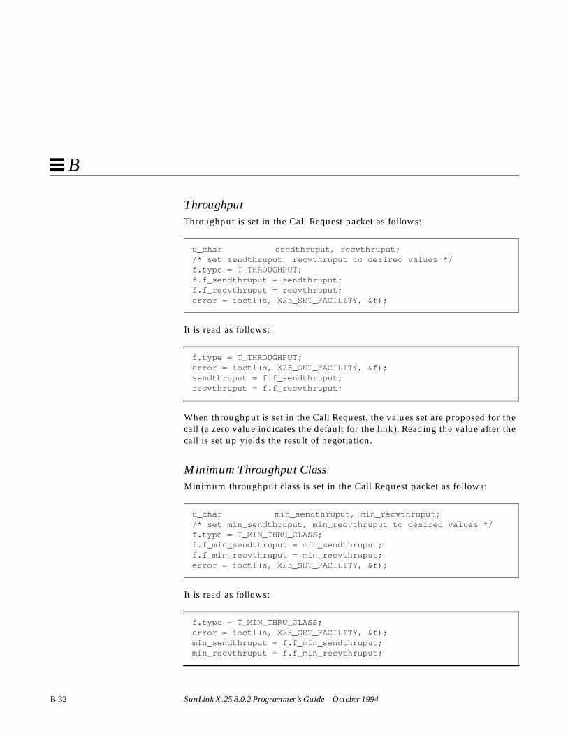
B-32 SunLink X.25 8.0.2 Programmer’s Guide—October 1994
B
ThroughputThroughput is set in the Call Request packet as follows:
It is read as follows:
When throughput is set in the Call Request, the values set are proposed for thecall (a zero value indicates the default for the link). Reading the value after thecall is set up yields the result of negotiation.
Minimum Throughput ClassMinimum throughput class is set in the Call Request packet as follows:
It is read as follows:
u_char sendthruput, recvthruput;/* set sendthruput, recvthruput to desired values */f.type = T_THROUGHPUT;f.f_sendthruput = sendthruput;f.f_recvthruput = recvthruput;error = ioctl(s, X25_SET_FACILITY, &f);
f.type = T_THROUGHPUT;error = ioctl(s, X25_GET_FACILITY, &f);sendthruput = f.f_sendthruput;recvthruput = f.f_recvthruput;
u_char min_sendthruput, min_recvthruput;/* set min_sendthruput, min_recvthruput to desired values */f.type = T_MIN_THRU_CLASS;f.f_min_sendthruput = min_sendthruput;f.f_min_recvthruput = min_recvthruput;error = ioctl(s, X25_SET_FACILITY, &f);
f.type = T_MIN_THRU_CLASS;error = ioctl(s, X25_GET_FACILITY, &f);min_sendthruput = f.f_min_sendthruput;min_recvthruput = f.f_min_recvthruput;
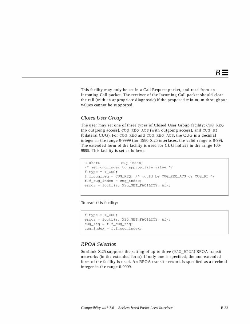
Compatiblity with 7.0— Sockets-based Packet Level Interface B-33
B
This facility may only be set in a Call Request packet, and read from anIncoming Call packet. The receiver of the Incoming Call packet should clearthe call (with an appropriate diagnostic) if the proposed minimum throughputvalues cannot be supported.
Closed User GroupThe user may set one of three types of Closed User Group facility: CUG_REQ(no outgoing access), CUG_REQ_ACS (with outgoing access), and CUG_BI(bilateral CUG). For CUG_REQ and CUG_REQ_ACS, the CUG is a decimalinteger in the range 0-9999 (for 1980 X.25 interfaces, the valid range is 0-99).The extended form of the facility is used for CUG indices in the range 100-9999. This facility is set as follows:
To read this facility:
RPOA SelectionSunLink X.25 supports the setting of up to three (MAX_RPOA) RPOA transitnetworks (in the extended form). If only one is specified, the non-extendedform of the facility is used. An RPOA transit network is specified as a decimalinteger in the range 0-9999.
u_short cug_index;/* set cug_index to appropriate value */f.type = T_CUG;f.f_cug_req = CUG_REQ; /* could be CUG_REQ_ACS or CUG_BI */f.f_cug_index = cug_index;error = ioctl(s, X25_SET_FACILITY, &f);
f.type = T_CUG;error = ioctl(s, X25_GET_FACILITY, &f);cug_req = f.f_cug_req;cug_index = f.f_cug_index;

B-34 SunLink X.25 8.0.2 Programmer’s Guide—October 1994
B
This facility is set as follows:
To read this facility:
Network Transit DelayThe Transit Delay Selection and Indication facility (TDSAI) is set in the CallRequest as follows:
This is read as follows:
u_short rpoa0, rpoa1, rpoa2;/* set rpoa0, rpoa1, rpoa2 */f.type = T_RPOA;f.f_nrpoa = 3;f.f_rpoa_index[0] = rpoa0;f.f_rpoa_index[1] = rpoa1;f.f_rpoa_index[2] = rpoa2;error = ioctl(s, X25_SET_FACILITY, &f);
f.type = T_RPOA;error = ioctl(s, X25_GET_FACILITY, &f);rpoa0 = f.f_rpoa_index[0];rpoa1 = f.f_rpoa_index[1];rpoa2 = f.f_rpoa_index[2];
u_short tr_delay;/* desired transit delay in milliseconds *//* set tr_delay */f.type = T_TR_DELAY;f.f_tr_delay = tr_delay;error = ioctl(s, X25_SET_FACILITY, &f);
f.type = T_TR_DELAY;error = ioctl(s, X25_GET_FACILITY, &f);tr_delay = f.f_tr_delay;

Compatiblity with 7.0— Sockets-based Packet Level Interface B-35
B
End-to-End Transit DelayThis is set in the Call Request as follows:
This is read as follows:
If f_desired_delay is set, f_req_delay must be non-zero; iff_max_delay is set, f_desired_delay must be non-zero. Delay is specifiedin milliseconds.
Network User IdentificationThis is set as follows (in the example below, NUI is an ASCII string):
SunLink X.25 permits a maximum length of 64 (MAX_NUI) for Network UserIdentification facility.
u_shortreq_delay, desired_delay, max_delay;/* set the requested, desired, and maximum delays */f.type = T_ETE_TR_DELAY;f.f_req_delay = req_delay;f.f_desired_delay = desired_delay;f.f_max_delay = max_delay;error = ioctl(s, X25_SET_FACILITY, &f);
f.type = T_ETE_TR_DELAY;error = ioctl(s, X25_GET_FACILITY, &f);req_delay = f.f_req_delay;desired_delay = f.f_desired_delay;max_delay = f.f_max_delay;
charnui_str[] = "sunhost";f.type = T_NUI;f.f_nui.nui_len = strlen(nui_str);bcopy(nui_str, f.f_nui.nui_data, strlen(nui_str));error = ioctl(s, X25_SET_FACILITY, &f);

B-36 SunLink X.25 8.0.2 Programmer’s Guide—October 1994
B
To read this facility:
Charging Information RequestThis write-only facility is set as follows:
Charging InformationBy setting f.type to T_CHARGE_REQ as specified above you make availablethe following read-only facilities. The facility types are T_CHARGE_MU,T_CHARGE_SEG, and T_CHARGE_DUR. For example, the Charging Information(monetary unit) is read as follows:
The T_CHARGE_SEG and T_CHARGE_DUR facilities are read in a way similar tothe T_CHARGE_MU example above; that is, by using T_CHARGE_SEG orT_CHARGE_DUR for the f.type value, and using f_charge_seg orf_charge_dur in place of f_charge_mu ).
f.type = T_NUI;error = ioctl(s, X25_GET_FACILITY, &f);nui_str = f.f_nui.nui_data;
f.type = T_CHARGE_REQ;f.f_charge_req = 1;error = ioctl(s, X25_SET_FACILITY, &f);
typedef struct charge_info_s {u_char charge_len;
#define MAX_CHARGE_INFO64u_char charge_data[MAX_CHARGE_INFO];
} CHARGE_INFO;
CHARGE_INFO charge_mu;f.type = T_CHARGE_MU;error = ioctl(s, X25_GET_FACILITY, &f);charge_mu = f.f_charge_mu;

Compatiblity with 7.0— Sockets-based Packet Level Interface B-37
B
The maximum length for the charging information facility permitted bySunLink X.25 is 64 (MAX_CHARGE_INFO). This facility should be read after thecall is cleared, but before the socket is closed, since it is received in the ClearRequest or Clear Confirm packets.
Called Line Address Modified NotificationThis is a read-only facility received in either the Call Accepted or ClearIndication packets. It is read as follows:
Call Redirection NotificationThis is a read-only facility received in either the Call Accepted or ClearIndication packets. It is read as follows:
Expedited Data NegotiationThis facility is set as follows:
u_charline_addr_mod;f.type = T_LINE_ADDR_MOD;error = ioctl(s, X25_GET_FACILITY, &f);line_addr_mod = f.f_line_addr_mod;
typedef struct call_redir_s {u_char cr_reason;u_char cr_hostlen;u_char cr_host[(MAXHOSTADR+1)/2];
} CALL_REDIR;
CALL_REDIR call_redir;f.type = T_CALL_REDIR;error = ioctl(s, X25_GET_FACILITY, &f);call_redir = f.f_call_redir;
u_char expedited = 1;/* 0 indicates non-use of expedited data */f.type = T_EXPEDITED;f.f_expedited = expedited;error = ioctl(s, X25_SET_FACILITY, &f);
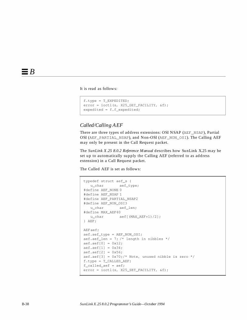
B-38 SunLink X.25 8.0.2 Programmer’s Guide—October 1994
B
It is read as follows:
Called/Calling AEFThere are three types of address extensions: OSI NSAP (AEF_NSAP), PartialOSI (AEF_PARTIAL_NSAP), and Non-OSI (AEF_NON_OSI). The Calling AEFmay only be present in the Call Request packet.
The SunLink X.25 8.0.2 Reference Manual describes how SunLink X.25 may beset up to automatically supply the Calling AEF (referred to as addressextension) in a Call Request packet.
The Called AEF is set as follows:
f.type = T_EXPEDITED;error = ioctl(s, X25_GET_FACILITY, &f);expedited = f.f_expedited;
typedef struct aef_s {u_char aef_type;
#define AEF_NONE 0#define AEF_NSAP 1#define AEF_PARTIAL_NSAP2#define AEF_NON_OSI3
u_char aef_len;#define MAX_AEF40
u_char aef[(MAX_AEF+1)/2];} AEF;
AEFaef;aef.aef_type = AEF_NON_OSI;aef.aef_len = 7; /* length in nibbles */aef.aef[0] = 0x12;aef.aef[1] = 0x34;aef.aef[2] = 0x56;aef.aef[3] = 0x70;/* Note, unused nibble is zero */f.type = T_CALLED_AEF;f_called_aef = aef;error = ioctl(s, X25_SET_FACILITY, &f);

Compatiblity with 7.0— Sockets-based Packet Level Interface B-39
B
The Called AEF is read as follows:
The Calling AEF is set and read similarly (using T_CALLING_AEF in place ofT_CALLED_AEF and f_calling_aef in place of f_called_aef ).
Non-X.25 FacilitiesThese are for expert use only. SunLink X.25 permits a maximum of 64(MAX_PRIVATE) bytes of non-X.25 facilities. These are not looked at bySunLink X.25, but just passed through. Non-X.25 facilities consist of a sequenceof facility blocks, where each block begins with a facility marker indicatingnon-X.25 facilities supported by either the local or remote network, or somearbitrary facility marker. This is set as follows:
It is read as follows:
f.type = T_CALLED_AEF;error = ioctl(s, X25_GET_FACILITY, &f);aef = f_called_aef;
typedef struct private_fact_s {u_char p_len; /* total length of facilities*/
#define MAX_PRIVATE 64u_char p_fact[MAX_PRIVATE];
/* facilities exactly as they * are present in Call Request or * Call Accept packets */
} PRIVATE_FACT;
PRIVATE_FACT private;/* set the p_len and p_fact fields */f.type = T_PRIVATE;f.f_private = private;error = ioctl(s, X25_SET_FACILITY, &f);
f.type = T_PRIVATE;error = ioctl(s, X25_GET_FACILITY, &f);private = f.f_private;
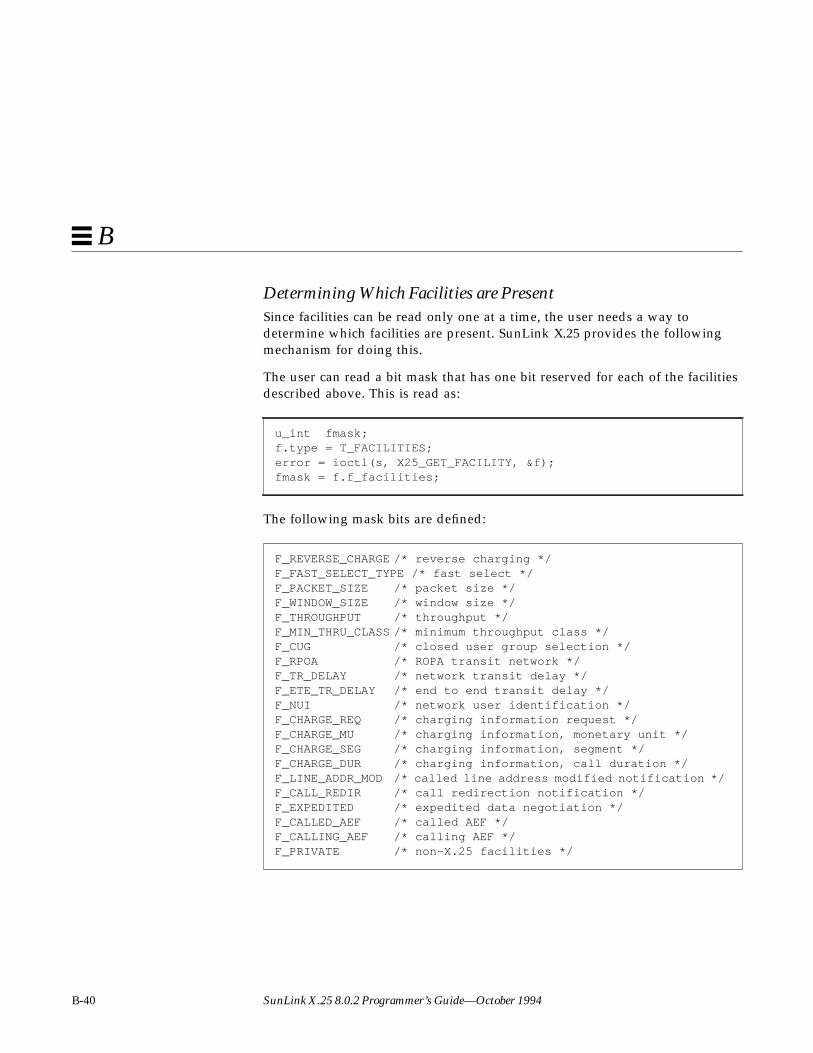
B-40 SunLink X.25 8.0.2 Programmer’s Guide—October 1994
B
Determining Which Facilities are PresentSince facilities can be read only one at a time, the user needs a way todetermine which facilities are present. SunLink X.25 provides the followingmechanism for doing this.
The user can read a bit mask that has one bit reserved for each of the facilitiesdescribed above. This is read as:
The following mask bits are defined:
u_int fmask;f.type = T_FACILITIES;error = ioctl(s, X25_GET_FACILITY, &f);fmask = f.f_facilities;
F_REVERSE_CHARGE /* reverse charging */F_FAST_SELECT_TYPE /* fast select */F_PACKET_SIZE /* packet size */F_WINDOW_SIZE /* window size */F_THROUGHPUT /* throughput */F_MIN_THRU_CLASS /* minimum throughput class */F_CUG /* closed user group selection */F_RPOA /* ROPA transit network */F_TR_DELAY /* network transit delay */F_ETE_TR_DELAY /* end to end transit delay */F_NUI /* network user identification */F_CHARGE_REQ /* charging information request */F_CHARGE_MU /* charging information, monetary unit */F_CHARGE_SEG /* charging information, segment */F_CHARGE_DUR /* charging information, call duration */F_LINE_ADDR_MOD /* called line address modified notification */F_CALL_REDIR /* call redirection notification */F_EXPEDITED /* expedited data negotiation */F_CALLED_AEF /* called AEF */F_CALLING_AEF /* calling AEF */F_PRIVATE /* non-X.25 facilities */

Compatiblity with 7.0— Sockets-based Packet Level Interface B-41
B
For example, to determine if the Call Redirection facility has been received, thefollowing segment of code could be used:
B.7.3 Fast Select User Data
The fast select facility is handled in the following way.
Calling SideTo send fast select data, fast_select_type must be set to the proper value(with the X25_SET_FACILITY ioctl) before connect is called (see the section“Facility Specification and Negotiation” on page B-26 of this chapter for moreinformation). Using the CONN_DB structure, a calling DTE can specify a userdata field up to 102 bytes (including the optional protocol identifier). If 102bytes of call user data are not enough for the current fast select message, usethe X25_WR_USER_DATA ioctl before calling connect to pass the additionaluser data. The user data specified in connect will precede this additional userdata. To write user data:
Here, MAX_USER_DATA is 124.
if ((fmask & F_CALL_REDIR) != 0) {/* * Read its value. */CALL_REDIR call_redir;f.type = T_CALL_REDIR;error = ioctl(s, X25_GET_FACILITY, &f);call_redir = f.f_call_redir;}
typedef struct user_data_db_s {u_char datalen;u_char data[MAX_USER_DATA];} USER_DATA_DB;int s, error;USER_DATA_DB user_data;error = ioctl(s, X25_WR_USER_DATA, &user_data)

B-42 SunLink X.25 8.0.2 Programmer’s Guide—October 1994
B
If connect returns –1 and errno is EFASTDATA, the remote side has clearedthe call by sending a Clear Indication packet with up to 32 bytes (1980) or 128bytes (1984) of user data. At this time, the user can read the user data in theClear Indication packet with calls to the X25_RD_USER_DATA ioctl until thereturned datalen in USER_DATA_DB structure is 0 or less thanMAX_USER_DATA, then close the socket with close .
To read user data:
If connect returns 0, it indicates that the connection has been set upsuccessfully. If the connection is over an interface that supports 1984 X.25, theremote user may have sent user data in the Call Accepted packet. (This willhappen only if the initiator of the connection has specified fast select with norestriction on response.) Thus the initiating user must repeatedly read any userdata using the X25_RD_USER_DATA ioctl until the returned length in theUSER_DATA_DB structure is less than MAX_USER_DATA.
When a call is cleared after being connected, the Clear Indication packet maycontain user data if the interface supports 1984 X.25 and fast select is in effectfor that call. Either the initiator of the connection or the responder can senduser data in the Clear Request packet. Thus when a call with fast select iscleared by the remote user, user data must be read in the same way as for theother cases.
For 1980 X.25 interfaces, if the connection was accepted by the remote user, theCall Accepted and Clear Request packets will not have any user data; the onlytime that the Clear Request can have user data is when a fast select call iscleared immediately (this is detectable by means of the EFASTDATA errorreturn).
Called SideTo receive a fast select incoming call, the called side must specify eitherFAST_ACPT_CLR or FAST_CLR_ONLY as the value for fast_select_typeusing the X25_SET_FACILITY ioctl, before issuing the listen call.
USER_DATA_DB user_data;int s, error;error = ioctl(s, X25_RD_USER_DATA, &user_data);
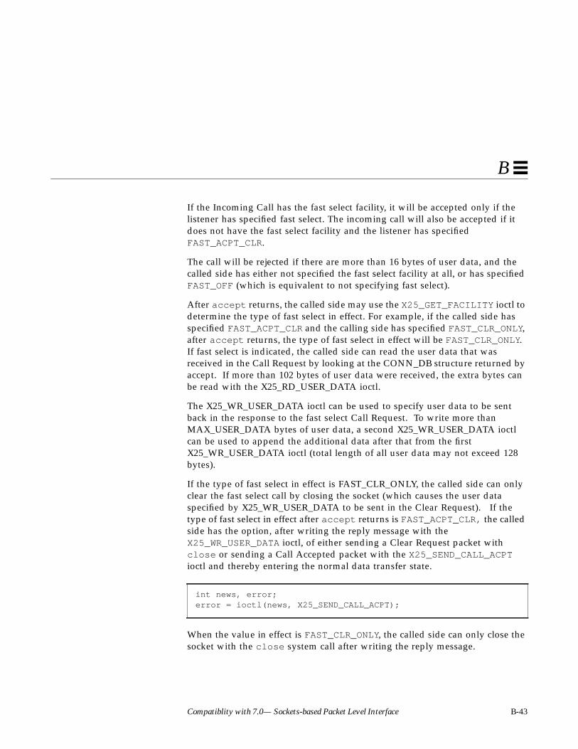
Compatiblity with 7.0— Sockets-based Packet Level Interface B-43
B
If the Incoming Call has the fast select facility, it will be accepted only if thelistener has specified fast select. The incoming call will also be accepted if itdoes not have the fast select facility and the listener has specifiedFAST_ACPT_CLR.
The call will be rejected if there are more than 16 bytes of user data, and thecalled side has either not specified the fast select facility at all, or has specifiedFAST_OFF (which is equivalent to not specifying fast select).
After accept returns, the called side may use the X25_GET_FACILITY ioctl todetermine the type of fast select in effect. For example, if the called side hasspecified FAST_ACPT_CLR and the calling side has specified FAST_CLR_ONLY,after accept returns, the type of fast select in effect will be FAST_CLR_ONLY.If fast select is indicated, the called side can read the user data that wasreceived in the Call Request by looking at the CONN_DB structure returned byaccept. If more than 102 bytes of user data were received, the extra bytes canbe read with the X25_RD_USER_DATA ioctl.
The X25_WR_USER_DATA ioctl can be used to specify user data to be sentback in the response to the fast select Call Request. To write more thanMAX_USER_DATA bytes of user data, a second X25_WR_USER_DATA ioctlcan be used to append the additional data after that from the firstX25_WR_USER_DATA ioctl (total length of all user data may not exceed 128bytes).
If the type of fast select in effect is FAST_CLR_ONLY, the called side can onlyclear the fast select call by closing the socket (which causes the user dataspecified by X25_WR_USER_DATA to be sent in the Clear Request). If thetype of fast select in effect after accept returns is FAST_ACPT_CLR, the calledside has the option, after writing the reply message with theX25_WR_USER_DATA ioctl, of either sending a Clear Request packet withclose or sending a Call Accepted packet with the X25_SEND_CALL_ACPTioctl and thereby entering the normal data transfer state.
When the value in effect is FAST_CLR_ONLY, the called side can only close thesocket with the close system call after writing the reply message.
int news, error;error = ioctl(news, X25_SEND_CALL_ACPT);

B-44 SunLink X.25 8.0.2 Programmer’s Guide—October 1994
B
FAST_OFF is the type of fast select that will be in effect when the listener hasspecified FAST_ACPT_CLR and the incoming call does not have the fast selectfacility. Even in this case, the listener must use the X25_SEND_CALL_ACPTioctl to put the connection into normal data transfer state.
Note – In the current release (and not in 7.0 SunNet X.25), the listen socketshould not be closed until after the incoming fast select call has been eithercleared (with close ) or accepted (with X25_SEND_CALL_ACPT).
B.7.4 Permanent Virtual Circuits
Since permanent virtual circuits are always in data transfer state, there is noneed to issue a connect on the calling side, or bind , listen , and accept onthe called side. Instead, use an ioctl call to bind the socket to a logical channelnumber and to specify other parameters.
In the current release, the sendpktsize , recvpktsize , sendwndsize , andrecvwndsize parameters are ignored. The default value in the linkconfiguration file is always used. By default, the lowest numbered WAN linkis used for the permanent virtual circuit. If you desire some other link for thepermanent virtual circuit, you must select the desired link using theX25_SET_LINK ioctl as described earlier, after the socket call, but before theX25_SETUP_PVC ioctl. Permanent virtual circuits are not supported over LANinterfaces.
typedef struct pvc_db_s {u_short lcn; /* lcn of PVC */u_short sendpktsize; /* Maximum packet size */u_short recvpktsize; /* Maximum packet size */u_char sendwndsize; /* Output flow control window */u_char recvwndsize; /* Input flow control window */} X25_PVC_DB;X25_PVC_DB pvc_parms;int pvc_so;pvc_so = socket(AF_X25, SOCK_STREAM, 0);error = ioctl(pvc_so, X25_SETUP_PVC, &pvc_parms);
Compatiblity with 7.0— Sockets-based Packet Level Interface B-45
B
B.7.5 Call Acceptance by User
Normally Incoming Call packets are examined and responded to by X.25. If thecall is accepted, a Call Accepted packet is sent by X.25 directly. In the event auser process wants to have additional checks before sending a Call Acceptedpacket, an X25_CALL_ACPT_APPROVAL ioctl may be used.
where approved_by_user = 0 means the approval is done by X.25, andapproved_by_user = 1 means approval is done by the user process. Bydefault (that is, if this call is not issued), approval is done by X.25. Note that ifa user wants to do call approval, the X25_CALL_ACPT_APPROVAL ioctl mustbe issued before the listen call is issued.
Regardless of the value of approved_by_user , X.25 always performs addressmatching and facilities negotiation before notifying accept . If a user processassumes the final incoming call approval, accept will return without sendinga Call Accepted packet. At this time, the user process should reply as soon aspossible to avoid the Call Request timeout on the remote calling side. To acceptthe call, use:
Here, news is the socket descriptor returned by accept .
The X25_SEND_CALL_ACPT ioctl call is also needed for fast select calls, asdescribed in an earlier section. To reject the call, simply close the socket:
where news is the socket descriptor returned by accept .
int approved_by_user, s, error;error = ioctl(s, X25_CALL_ACPT_APPROVAL, &approved_by_user);
int news, error;error = ioctl(news, X25_SEND_CALL_ACPT);
int news;close(news);

B-46 SunLink X.25 8.0.2 Programmer’s Guide—October 1994
B
B.7.6 Accessing the Link (X.25) Address
The X.25 client can set the local link X.121 (X.25) address through an X.25socket owned by the superuser. (The default value is established in theInterface Configuration window in x25tool , as described in theSunLink X.258.0.2 Reference Manual):
Set linkid to the identifier of the desired link.
The local link X.121 address can be read at any time with:
The returned addr is actually the link address specified in x25tool (for thelink specified in the linkid field of the LINK_ADR structure) unless a newaddress has been assigned to the link.
The X25_WR_LINKADR ioctl can be used to assign new X.25 addresses to alink.
B.7.7 Accessing High Water Marks of Socket
The AF_X25 socket provides a flow control mechanism using high and lowwater marks on both the send and receive sides of an X.25 virtual circuit. Whenthe amount of queued data goes above the high water mark, additional data isblocked until the queued data falls below the low water mark. Blockingreceived data is accomplished by not acknowledging receipt of packets untilthe user reads the data. Blocking send data is accomplished by blocking theuser process invoking send or write .
typedef struct link_adr_s {int linkid; /* id of link */u_char hostlen; /* length of BCDs */u_char host[(MAXHOSTADR+1)/2];
} LINK_ADR;LINK_ADR addr;int so, error;error = ioctl(so, X25_WR_LINKADR, &addr);
LINK_ADR addr;int s;error = ioctl(s, X25_RD_LINKADR, &addr);

Compatiblity with 7.0— Sockets-based Packet Level Interface B-47
B
The default high water mark for both sending and receiving is 2048 bytes. Thelow water mark is always set to half the high water mark. Note that the highwater mark is only an approximation of the maximum amount of data allowedto be queued up.
A user process may set or read the high water mark as described below. Toread:
To write:
typedef struct so_hiwat_db_s {short sendhiwat;short recvhiwat;
} SO_HIWAT_DB;SO_HIWAT_DB hiwater;int s, error;error = ioctl(s, X25_RD_SBHIWAT, &hiwater);
error = ioctl(s, X25_WR_SBHIWAT, &hiwater);
B-48 SunLink X.25 8.0.2 Programmer’s Guide—October 1994
B
B.7.8 Accessing the Diagnostic Code
The user may read the cause or diagnostic code in a Clear Indication or ResetIndication packet received from the remote end. The user may also write thecause or diagnostic code in Clear Request and Reset Request packets to betransmitted to the remote end.
To read:
To write:
The data field in X25_CAUSE_DIAG contains the cause and diagnostic code.
typedef struct x25_cause_diag_s {u_charflags;# define RECV_DIAG 0# define DIAG_TYPE1# define WAIT_CONFIRMATION 2/* bit 0 (RECV_DIAG)= * 0: no cause and diagnostic codes * 1: receive cause and diagnostic codes. * bit 1 (DIAG_TYPE)= * 0: reset cause and diagnostic codes in data array * 1: clear cause and diagnostic codes in data array * bit 2 (WAIT_CONFIRMATION)= * 0: no wait after X25_WR_DIAG_CODE ioctl * 1: wait returned cause and diagnostic codes after * X25_WR_DIAG_CODE ioctl. */
u_char datalen; /* byte count of data array */u_char data[64];
} X25_CAUSE_DIAG;X25_CAUSE_DIAG diag;int s, error;
error = ioctl(s, X25_RD_CAUSE_DIAG, &diag);
error = ioctl(s, X25_WR_CAUSE_DIAG, &diag);
Compatiblity with 7.0— Sockets-based Packet Level Interface B-49
B
Upon receiving a Clear Indication or Reset Indication packet, theX25_RD_CAUSE_DIAG ioctl may be issued to determine the cause anddiagnostic associated with the packet. The datalen field contains the lengthin bytes of the information in data . When reading the diagnostic, if bitRECV_DIAG (that is, bit 0) is set, it indicates that the information in data isvalid. If bit DIAG_TYPE (that is, bit 1) is set, it indicates that the diagnostic wasreceived in a Clear Indication; otherwise, it was received in a Reset Indication.
The X25_WR_CAUSE_DIAG ioctl enables the user to send a Clear Request orReset Request packet with the desired cause and diagnostic codes. If the usersupplies only one byte in the data field, X.25 will use the cause codeDTE_ORIGINATED, and use the provided byte as the diagnostic.
The X25_WR_CAUSE_DIAG ioctl call will send a Clear Request or ResetRequest. To send a Clear Request, set bit DIAG_TYPE (that is, bit 1) in flags :
To send a Clear Request and wait for confirmation, set bitWAIT_CONFIRMATION (that is, bit 2) in flags :
X25_CAUSE_DIAG diag;int s, error;diag.flags = 1 << DIAG_TYPE; /* Clear Request */diag.datalen = 2;diag.data[0] = 0;diag.data[1] = 67;error = ioctl(s, X25_WR_CAUSE_DIAG, &diag);
X25_CAUSE_DIAG diag;int s, error;diag.flags = (1 << DIAG_TYPE) | (1 << WAIT_CONFIRMATION);diag.datalen = 2;diag.data[0] = 0;diag.data[1] = 67;error = ioctl(s, X25_WR_CAUSE_DIAG, &diag);

B-50 SunLink X.25 8.0.2 Programmer’s Guide—October 1994
B
To send a Reset Request and wait for confirmation:
A close is still necessary to free all resources held by this socket and theassociated virtual circuit after a Clear Indication or Clear Confirmation packetis received. After the DTE receives a Clear Indication packet, recv will returnzero bytes after all unread data has been read. Calling send after the ClearIndication packet is received will not return an error. Note that this behavior isdifferent from that of 7.0 SunLink X.25, in which send does return an error.
To be notified when a Clear Indication packet is received, so that you can usethe X25_RD_CAUSE_DIAG ioctl, you can use the following mechanism: Enablea third type of out-of-band data (see “Out-of-Band Data” on page B-23) andreceive the SIGURG signal when this type of out-of-band data arrives. Toenable the signalling of Clear Indication packets, use the following ioctl:
This will enable the reception of the following type of out-of-band data, whichcan be read with the X25_OOB_TYPE ioctl:
See “Out-of-Band Data” on page B-23 for a complete description of how tohandle out-of-band data.
Note – If an X25_WR_CAUSE_DIAG ioctl is not issued before close , X.25 fillsan appropriate cause and diagnostic code in any Clear Request packet sent as aresult (this will not happen if the connection is inactive at the time the call isissued).
X25_CAUSE_DIAG diag;int s, error;diag.flags = 1 << WAIT_CONFIRMATION;diag.datalen = 2;diag.data[0] = 0;diag.data[1] = 0;/* can be any valid diagnostic */error = ioctl(s, X25_WR_CAUSE_DIAG, &diag);
error = ioctl(s, X25_OOB_ON_CLEAR, 0);
#define VC_CLEARED 31 /* virtual circuit cleared */

Compatiblity with 7.0— Sockets-based Packet Level Interface B-51
B
B.8 Routing ioctlsIn this section, we describe the ioctls used to manage the SunLink X.25 routingfunction in the sockets-based interface. The SunLink X.25 routing function isdescribed in detail in the SunLink X.25 8.0.2 Reference Manual. The datastructure used for routing is as follows:
The following declarations will be used in the code segments used forillustration:
To add a route, set the fields in the X25_ROUTE structure to desired values, andexecute the X25_ADD_ROUTE ioctl as follows:
typedef struct x25_route_s { caddr_t index; u_char r_type;#define R_NONE 0#define R_X121_HOST 1#define R_X121_PREFIX 2#define R_AEF_HOST 3#define R_AEF_PREFIX 4 CONN_ADR x121; u_char pid_len;#define MAX_PID_LEN 4 u_char pid[MAX_PID_LEN]; AEF aef; int linkid; X25_MACADDR mac; int use_count; char reserved[16];} X25_ROUTE;
int s, error;X25_ROUTE r;
error = ioctl(s, X25_ADD_ROUTE, &r);

B-52 SunLink X.25 8.0.2 Programmer’s Guide—October 1994
B
To obtain the routing information for a given destination address, set thedestination address in the X25_ROUTE structure and execute theX25_GET_ROUTE ioctl:
To remove a route for a given destination address, set the destination addressin the X25_ROUTE structure and execute the X25_RM_ROUTE ioctl:
To flush all routes out, execute the X25_FLUSH_ROUTES ioctl:
The following code segment illustrates how one may cycle through all theroutes configured in the system and obtain the parameters for each of them:
When there are no routes left, error will be -1, and errno will be set toENOENT.
The X25_ADD_ROUTE, X25_RM_ROUTE, and X25_FLUSH_ROUTES ioctls requiresuperuser privilege; X25_GET_ROUTE and X25_GET_NEXT_ROUTE do not.
B.9 Miscellaneous ioctlsThis section describes some miscellaneous ioctl calls that were either notcovered in the previous sections, or are supported from previous releases forbackward compatibility. This does not imply backward compatibility with alluser-written software for previous releases of SunLink X.25.
error = ioctl(s, X25_GET_ROUTE, &r);
error = ioctl(s, N_X25_RM_ROUTE, &r);
error = ioctl(s, X25_FLUSH_ROUTES);
r.index = 0;do { error = ioctl(s, X25_GET_NEXT_ROUTE, &r); if (error == 0) /* print the route */;while (error == 0);
Compatiblity with 7.0— Sockets-based Packet Level Interface B-53
B
B.9.1 Obtaining Statistics
Use the X25_GET_NLINKS ioctl to determine the number of links configured:
The X.25 software maintains statistics for levels 1, 2, and 3. The statistics aremade available for any socket at any time (that is, the sockets over which thecalls for reading statistics are issued need not have superuser privilege).
int s, error, nlinks;error = ioctl(s, X25_GET_NLINKS, &nlinks);

B-54 SunLink X.25 8.0.2 Programmer’s Guide—October 1994
B
The X25_RD_LINK_STATISTICS ioctl is used to read statistics of levels 1 and2:
The linkid field in the X25_LINK_STAT_DB structure identifies the interfacewhose statistics are to be read.
struct ss_dstats {long ssd_ipack; /* input packets */long ssd_opack; /* output packets */long ssd_ichar; /* input bytes */long ssd_ochar; /* output bytes */
};
/* error stats */struct ss_estats {
long sse_abort; /* abort received */long sse_crc; /* CRC error */long sse_overrun; /* receiver overrun */long sse_underrun; /* xmitter underrun */
};typedef struct x25_link_stat_db_s {
int linkid; /* link identifier */u_short state;/* 0: initial state * 1: SABM outstanding * 2: FRMR outstanding * 3: DISC outstanding * 4: information transfer state */u_short hs_sentsabms; /* sabms sent */struct ss_dstats hs_data; /* data stats */struct ss_estats hs_errors; /* error stats */
} X25_LINK_STAT_DB;
X25_LINK_STAT_DB link_stats;int s, error;error = ioctl(s, X25_RD_LINK_STATISTICS, &link_stats);

Compatiblity with 7.0— Sockets-based Packet Level Interface B-55
B
The X25_RD_PKT_STATISTICS ioctl is used for reading packet-level statisticsfor a specified logical channel:
typedef struct x25_pkt_stat_db_s {int linkid; /* link identifier */u_short lcn; /* logical channel identifier */u_char state; /* level 3 lcn state */
/* current state of virtual circuitST_OFF (0): virtual circuit not activeST_LISTEN (1): passive wait for incoming callST_READY (2): connection in process of being established (connection NOT up yet)ST_SENT_CALL (3): wait for call connected packetST_RECV_CALL (4): wait user to send call accepted packetST_CALL_COLLISION (5): call collision stateST_RECV_CLR (6): unused (should indicate reception of a
clear packet)ST_SENT_CLR (7): wait for clear confirmation packetST_DATA_TRANSFER (8): in normal data transferST_SENT_RES (9): wait reset confirmation packet
*/u_char sub_state; /* level 3 lcn sub_state *//* valid only when state is ST_DATA_TRANSFER bit 0 (RECV_RNR): remote busy bit 1 (RECV_INT): wait user to read interrupt data bit 2 (SENT_INT): wait for interrupt confirmation bit 3 (SENT_RNR): local busy*/u_char intcnt; /* number of received interrupt datum */u_char resetcnt; /* times of virtual circuit reset */int sendpkts; /* number of output packets */int recvpkts; /* number of input packets */short pgrp; /* process group of socket, if not 0 */short flags; /* flag bits. If bit 0 is set, it *//* indicates an incoming call. *//* Otherwise, it is an outgoing call. */
} X25_PKT_STAT_DB;
X25_PKT_STAT_DB pkt_stats;int s, error;error = ioctl(s, X25_RD_PKT_STATISTICS, &pkt_stats);

B-56 SunLink X.25 8.0.2 Programmer’s Guide—October 1994
B
The linkid field in the X25_PKT_STAT_DB structure identifies a link, andlcn identifies the logical channel whose statistics are to be read. Note thatpkt_stats.lcn needs to be set to the proper logical channel number beforemaking the X25_RD_PKT_STATISTICS ioctl call.
SunLink X.25 also provides ioctl commands to read the status of all of thelinks currently active and all the virtual circuits currently active. Use theX25_GET_NEXT_LINK_STAT ioctl to obtain link status as follows:
/* The following is used to cycle through all the interfaces - * static HDLC links as well as links used for LLC2. */typedef struct x25_next_link_stat_s {
u_char opt; /* search option */#define GET_FIRST 0/* get first one */#define GET_NEXT 1/* get next one */
u_char specific; /* applies to specified interface */u_char link_type; /* HDLC_TYPE, LLC_TYPE */int linkid; /* interface id */X25_MACADDR mac; /* always null in current release */
/* Level 2 states */#define LINKSTATE_DOWN 0 /* initial state */#define LINKSTATE_SABM 1 /* SABM outstanding */#define LINKSTATE_FRMR 2 /* FRMR outstanding */#define LINKSTATE_DISC 3 /* DISC outstanding */#define LINKSTATE_UP 4 /* info transfer state */
u_short state; /* link state--see preceding defines */u_short hs_sentsabms; /* sabms sent */struct ss_dstats hs_data; /* data stats */struct ss_estats hs_errors; /* error stats */
} X25_NEXT_LINK_STAT;
int s;int error;X25_NEXT_LINK_STAT lstats;
lstats.opt = GET_FIRST;lstats.specific = 0;do { error = ioctl(s, X25_GET_NEXT_LINK_STAT, &lstats); if (error == 0) /* print the statistics */; } while (error == 0);

Compatiblity with 7.0— Sockets-based Packet Level Interface B-57
B
If the statistics for a specific link are required, set specific to 1, and linkidto the id of the interface whose statistics are required. After the first call, theopt field will automatically be changed to GET_NEXT. When the statistics forall the links are returned, error will be -1, and errno will be set to ENOENT.
Use the X25_GET_NEXT_VC_STAT ioctl to obtain the status of all the virtualcircuits as follows:
Code Example B-1 Reading Virtual Circuit Status
/* X25_NEXT_VC_STAT is used to cycle through all virtual circuits, * over HDLC as well as LLC type links. */typedef struct x25_next_vc_stat_s {
u_char opt; /* search option */u_char specific; /* applies to specified linkid */u_char link_type; /* HDLC_TYPE, LLC_TYPE */int linkid; /* link id */u_short lcn; /* logical channel to return */u_char state; /* level 3 lcn state */
#define ST_OFF 0#define ST_LISTEN 1#define ST_READY 2#define ST_SENT_CALL 3#define ST_RECV_CALL 4#define ST_CALL_COLLISION 5#define ST_RECV_CLR 6#define ST_SENT_CLR 7#define ST_DATA_TRANSFER 8#define ST_SENT_RES 9
u_char sub_state; /* level 3 lcn sub_state */#define RECV_RNR 0#define RECV_INT 1#define SENT_INT 2#define SENT_RNR 3
u_char intcnt; /* number of received interrupts */u_char resetcnt; /* times of virtual circuit reset */int sendpkts; /* number of output packets */int recvpkts; /* number of input packets */short pgrp; /* process group, if any */short flags; /* various flags for future */
#define INCOMING_CALL 0x01#define IS_A_PVC 0x02
struct sockaddr sa; /* Remote X.121/IP address */AEF aef; /* Remote AEF, if any */X25_MACADDR mac; /* Remote mac for LLC links */

B-58 SunLink X.25 8.0.2 Programmer’s Guide—October 1994
B
If the statistics of virtual circuits for a specific link are required, set specificto 1, and linkid to the id of the desired interface. After the first call, the optfield will automatically be changed to GET_NEXT. When the statistics for all thevirtual circuits are returned, error will be -1, and errno will be set toENOENT.
B.9.2 Obtaining Version Number
The X25_VERSION ioctl returns the version number of the SunLink X.25 kernelcode. You can issue this call on any socket. The version number returned forthe current release of SunLink X.25 is 80.
} X25_NEXT_VC_STAT;
int s;int error;X25_NEXT_VC_STAT vstats;
vstats.opt = GET_FIRST;vstats.specific = 0;do { error = ioctl(s, X25_GET_NEXT_VC_STAT, &vstats); if (error == 0) /* print the statistics */; } while (error == 0);
int so, version, error;error = ioctl(s, X25_VERSION, &version);
Code Example B-1 Reading Virtual Circuit Status

C-1
Sockets Programming Example C
This appendix discusses include files and structures, and provides references toexample code.
Note – The sockets-based interface is a source-compatible—not a binary-compatible—interface. Applications that used the socket interface in SunOS4.x must be recompiled (using /usr/ucb/cc )to run on SunOS 5.x. SeeSection C.2, “Compilation Instructions and Sample Programs” for instructionson compiling programs to use the sockets-based interface on SunOS 5.0.
C.1 Include Files for User ProgramsSockets-based SunLink X.25 application programs need to have the followinginclude statements in addition to any standard SunOS system files that may beneeded:
This is illustrated in the sample programs provided.
#include <sys/iocom.h>#include <sys/types.h>#include <sys/socket.h>#include <sundev/syncstat.h>#include <netx25/x25_pk.h>#include <netx25/x25_ctl.h>#include <netx25/x25_ioctl.h>

C-2 SunLink X.25 8.0.2 Programmer’s Guide—October 1994
C
C.2 Compilation Instructions and Sample ProgramsTo use the 7.0 socket interface, user programs must be built with the/usr/ucb/cc compiler, and should be linked against libsockx25.a , storedin /opt/SUNWconn/lib . Use the -L option to link the /opt/SUNWconn/libdirectory into your program. A program named test can be linked againstthe socket library as follows:
You can find sample programs for the 7.0 socket interface in/opt/SUNWconn/x25/samples.socket .
C.3 Structures Used by the X25_SET_FACILITY and X25_GET_FACILITYioctl Commands
The following structures were referenced in the section “TheX25_SET_FACILITY and X25_GET_FACILITY ioctl Commands", on page B-26.:
hostname% /usr/ucb/cc -o test test.c -lsockx25 -L/opt/SUNWconn/lib
Code Example C-1 Structures Used by ioctls that Set and Get X.25 Facilities (1 of 6)
/* Packet sizes allowed are 0 (default), 16, 32, 64, * 128, 256, 512, 1024,2048, 4096 */
typedef struct packet_size_s {u_short sendpktsize;u_short recvpktsize;} PACKET_SIZE;
/* window sizes allowed are 0: * (default), 1-7 (normal), 1-127 (extended) */
typedef struct window_size_s {u_char sendwndsize;u_char recvwndsize;
} WINDOW_SIZE;/* throughput values allowed are * 0 (default), 3 (75) , 4 (150), 5 (300), * 6 (600), 7 (1200), 8 (2400), 9 (4800), * 10 (9600), 11 (19200), 12 (48000) */

Sockets Programming Example C-3
C
typedef struct throughput_s {u_char sendthruput:4;u_char recvthruput:4;
} THROUGHPUT;
typedef struct cug_s {u_char cug_req;
#define CUG_NONE 0 /* no CUG */#define CUG_REQ 1 /* CUG */#define CUG_REQ_ACS 2 /* CUG with outgoing access */#define CUG_BI 3 /* bilateral CUG */
u_short cug_index;} CUG;
typedef struct rpoa_s {u_char nrpoa; /* number of RPOAs requested */
#define MAX_RPOA 3u_short rpoa_index[MAX_RPOA]; /* rpoas;
nrpoa = 1 => normal format */} RPOA;/* Zero value for a field means the field is not specified; if a * field has zero value, that and the foll. fields are not sent. */
typedef struct ete_tr_delay_s {u_short req_delay;u_short desired_delay;u_short max_delay;
} ETE_TR_DELAY;
typedef struct nui_s {u_char nui_len; /* NUI length */
#define MAX_NUI 64u_char nui_data[MAX_NUI] /* NUI */
} NUI;
typedef struct charge_info_s {u_char charge_len;
#define MAX_CHARGE_INFO 64u_char charge_data[MAX_CHARGE_INFO];
} CHARGE_INFO;
typedef struct call_redir_s {
Code Example C-1 Structures Used by ioctls that Set and Get X.25 Facilities (2 of 6)
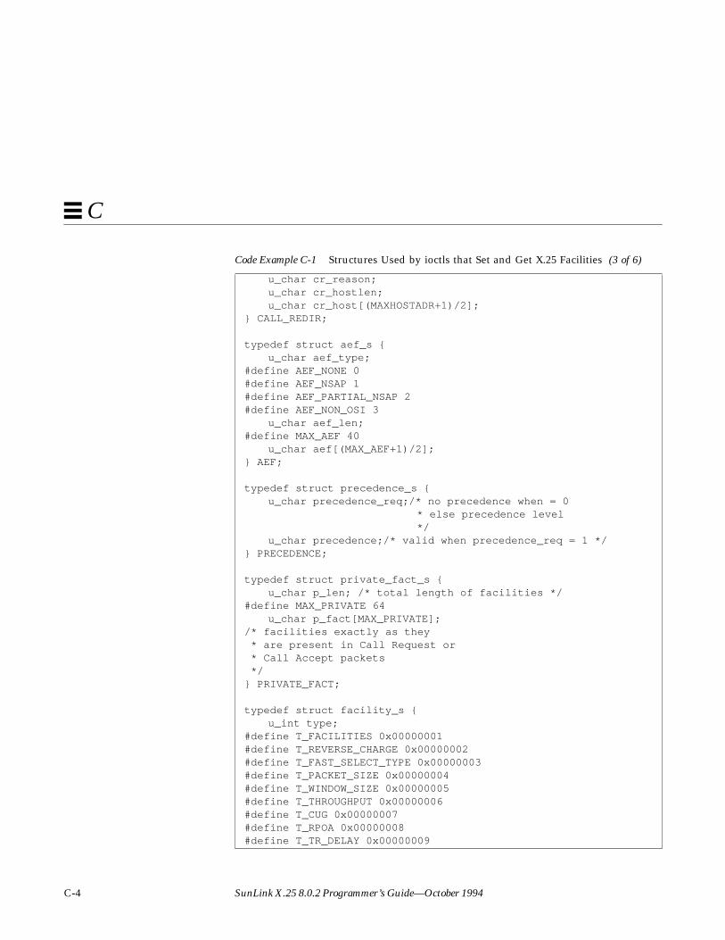
C-4 SunLink X.25 8.0.2 Programmer’s Guide—October 1994
C
u_char cr_reason;u_char cr_hostlen;u_char cr_host[(MAXHOSTADR+1)/2];
} CALL_REDIR;
typedef struct aef_s {u_char aef_type;
#define AEF_NONE 0#define AEF_NSAP 1#define AEF_PARTIAL_NSAP 2#define AEF_NON_OSI 3
u_char aef_len;#define MAX_AEF 40
u_char aef[(MAX_AEF+1)/2];} AEF;
typedef struct precedence_s {u_char precedence_req;/* no precedence when = 0
* else precedence level */
u_char precedence;/* valid when precedence_req = 1 */} PRECEDENCE;
typedef struct private_fact_s {u_char p_len; /* total length of facilities */
#define MAX_PRIVATE 64u_char p_fact[MAX_PRIVATE];
/* facilities exactly as they * are present in Call Request or * Call Accept packets */} PRIVATE_FACT;
typedef struct facility_s {u_int type;
#define T_FACILITIES 0x00000001#define T_REVERSE_CHARGE 0x00000002#define T_FAST_SELECT_TYPE 0x00000003#define T_PACKET_SIZE 0x00000004#define T_WINDOW_SIZE 0x00000005#define T_THROUGHPUT 0x00000006#define T_CUG 0x00000007#define T_RPOA 0x00000008#define T_TR_DELAY 0x00000009
Code Example C-1 Structures Used by ioctls that Set and Get X.25 Facilities (3 of 6)

Sockets Programming Example C-5
C
#define T_MIN_THRU_CLASS 0x0000000a#define T_ETE_TR_DELAY 0x0000000b#define T_NUI 0x0000000c#define T_CHARGE_REQ 0x0000000d#define T_CHARGE_MU 0x0000000e#define T_CHARGE_SEG 0x0000000f#define T_CHARGE_DUR 0x00000010#define T_LINE_ADDR_MOD 0x00000011#define T_CALL_REDIR 0x00000012#define T_EXPEDITED 0x00000013#define T_CALLED_AEF 0x00000014#define T_CALLING_AEF 0x00000015#define T_STDSERVICE 0x00000016#define T_OSISERVICE 0x00000017#define T_PRECEDENCE 0x00000018#define T_PRIVATE 0x00000019
union {u_intfacilities;/* quick way to check
* if a facility is present */
#define F_REVERSE_CHARGE 0x00000001#define F_FAST_SELECT_TYPE 0x00000002#define F_PACKET_SIZE 0x00000004#define F_WINDOW_SIZE 0x00000008#define F_THROUGHPUT 0x00000010#define F_MIN_THRU_CLASS 0x00000020#define F_CUG 0x00000040#define F_RPOA 0x00000080#define F_TR_DELAY 0x00000100#define F_ETE_TR_DELAY 0x00000200#define F_NUI 0x00000400#define F_CHARGE_REQ 0x00000800#define F_CHARGE_MU 0x00001000#define F_CHARGE_SEG 0x00002000#define F_CHARGE_DUR 0x00004000#define F_LINE_ADDR_MOD 0x00008000#define F_CALL_REDIR 0x00010000#define F_EXPEDITED 0x00020000#define F_CALLED_AEF 0x00040000#define F_CALLING_AEF 0x00080000#define F_STDSERVICE 0x00100000#define F_OSISERVICE 0x00200000#define F_PRECEDENCE 0x00400000
Code Example C-1 Structures Used by ioctls that Set and Get X.25 Facilities (4 of 6)

C-6 SunLink X.25 8.0.2 Programmer’s Guide—October 1994
C
#define F_PRIVATE 0x00800000u_char reverse_charge;
/* permit/request reverse charge */u_char fast_select_type;
#define FAST_OFF 0 /* don't use fast select */#define FAST_CLR_ONLY 1 /* restricted response */#define FAST_ACPT_CLR 2 /* unrestricted response */
PACKET_SIZE packet_size; /* packet sizes */WINDOW_SIZE window_size; /* window sizes */THROUGHPUT throughput; /* used for throughput
negotiation */THROUGHPUT min_thru_class; /* minimum throughput class */CUG cug; /* closed user group */RPOA rpoa; /* RPOA specification */u_short tr_delay; /* network transit delay */ETE_TR_DELAY ete_tr_delay; /* end-to-end transit delay */NUI nui; /* network user identification */u_char charge_req; /* request charging info */CHARGE_INFO charge_mu; /* charging info, monetary unit */CHARGE_INFO charge_seg; /* charging info, segment */CHARGE_INFO charge_dur; /* charging info, call duration */u_char line_addr_mod; /* called line addr modified */CALL_REDIR call_redir; /* call redirect notification */u_char expedited; /* expedited data negotiation */AEF called_aef; /* called aef */AEF calling_aef; /* calling aef */u_char osiservice; /* set when VC carries CLNP data */u_char stdservice; /* set for DDN services */PRECEDENCE prec; /* precedence for standard services */PRIVATE_FACT private; /* non-X.25 local/rem facilities */
} facility;} FACILITY;
/* Some convenient definitions. */#define f_facilities facility.facilities#define f_reverse_chargefacility.reverse_charge#define f_fast_select_typefacility.fast_select_type#define f_packet_size facility.packet_size#define f_recvpktsize facility.packet_size.recvpktsize#define f_sendpktsize facility.packet_size.sendpktsize#define f_window_size facility.window_size#define f_recvwndsize facility.window_size.recvwndsize#define f_sendwndsize facility.window_size.sendwndsize#define f_throughput facility.throughput
Code Example C-1 Structures Used by ioctls that Set and Get X.25 Facilities (5 of 6)

Sockets Programming Example C-7
C
#define f_recvthruput facility.throughput.recvthruput#define f_sendthruput facility.throughput.sendthruput#define f_min_thru_classfacility.min_thru_class#define f_min_recvthruputfacility.min_thru_class.recvthruput#define f_min_sendthruputfacility.min_thru_class.sendthruput#define f_cug facility.cug#define f_cug_req facility.cug.cug_req#define f_cug_index facility.cug.cug_index#define f_rpoa facility.rpoa#define f_nrpoa facility.rpoa.nrpoa#define f_rpoa_req facility.rpoa.rpoa_req#define f_tr_delay facility.tr_delay#define f_ete_tr_delay facility.ete_tr_delay#define f_req_delay facility.ete_tr_delay.req_delay#define f_desired_delay facility.ete_tr_delay.desired_delay#define f_max_delay facility.ete_tr_delay.max_delay#define f_nui facility.nui#define f_charge_req facility.charge_req#define f_charge_mu facility.charge_mu#define f_charge_seg facility.charge_seg#define f_charge_dur facility.charge_dur#define f_line_addr_mod facility.line_addr_mod#define f_call_redir facility.call_redir#define f_cr_reason facility.call_redir.cr_reason#define f_cr_hostlen facility.call_redir.cr_hostlen#define f_cr_host facility.call_redir.cr_host#define f_expedited facility.expedited#define f_called_aef facility.called_aef#define f_cd_aef_type facility.called_aef.aef_type#define f_cd_aef_len facility.called_aef.aef_len#define f_cd_aef facility.called_aef.aef#define f_calling_aef facility.calling_aef#define f_cg_aef_type facility.calling_aef.aef_type#define f_cg_aef_len facility.calling_aef.aef_len#define f_cg_aef facility.calling_aef.aef#define f_osiservice facility.osiservice#define f_stdservice facility.stdservice#define f_prec facility.prec#define f_precedence_reqfacility.prec.precedence_req#define f_precedence facility.prec.precedence#define f_private facility.private
Code Example C-1 Structures Used by ioctls that Set and Get X.25 Facilities (6 of 6)
C-8 SunLink X.25 8.0.2 Programmer’s Guide—October 1994
C
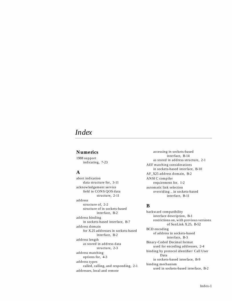
Index-1
Index
Numerics1988 support
indicating, 7-23
Aabort indication
data structure for, 3-11acknowledgement service
field in CONS QOS datastructure, 2-11
addressstructure of, 2-2structure of in sockets-based
interface, B-2address binding
in sockets-based interface, B-7address domain
for X.25 addresses in sockets-basedinterface, B-2
address lengthas stored in address data
structure, 2-3address matching
options for, 4-3address types
called, calling, and responding, 2-1addresses, local and remote
accessing in sockets-basedinterface, B-14
as stored in address structure, 2-1AEF matching considerations
in sockets-based interface, B-10AF_X25 address domain, B-2ANSI C compiler
requirement for, 1-2automatic link selection
overriding .. in sockets-basedinterface, B-11
Bbackward compatibility
interface description, B-1restrictions on, with previous versions
of SunLink X.25, B-52BCD encoding
of address in sockets-basedinterface, B-3
Binary-Coded Decimal formatused for encoding addresses, 2-4
binding by protocol identifier/Call UserData
in sockets-based interface, B-9binding mechanism
used in sockets-based interface, B-2
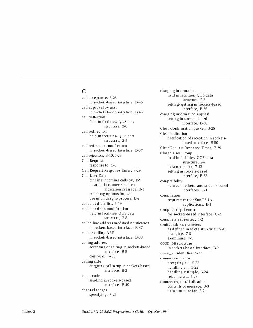
Index-2 SunLink X.25 8.0.2 Programmer’s Guide—October 1994
Ccall acceptance, 5-23
in sockets-based interface, B-45call approval by user
in sockets-based interface, B-45call deflection
field in facilities/QOS datastructure, 2-8
call redirectionfield in facilities/QOS data
structure, 2-8call redirection notification
in sockets-based interface, B-37call rejection, 3-10, 5-23Call Request
response to, 5-6Call Request Response Timer, 7-29Call User Data
binding incoming calls by, B-9location in connect/request
indication message, 3-3matching options for, 4-2use in binding to process, B-2
called address list, 5-19called address modification
field in facilities/QOS datastructure, 2-8
called line address modified notificationin sockets-based interface, B-37
called/calling AEFin sockets-based interface, B-38
calling addressaccepting or setting in sockets-based
interface, B-5control of, 7-38
calling sideoutgoing call setup in sockets-based
interface, B-3cause code
sending in sockets-basedinterface, B-49
channel rangesspecifying, 7-25
charging informationfield in facilities/QOS data
structure, 2-8setting/getting in sockets-based
interface, B-36charging information request
setting in sockets-basedinterface, B-36
Clear Confirmation packet, B-26Clear Indication
notification of reception in sockets-based interface, B-50
Clear Request Response Timer, 7-29Closed User Group
field in facilities/QOS datastructure, 2-7
parameters for, 7-33setting in sockets-based
interface, B-33compatibility
between sockets- and streams-basedinterfaces, C-1
compilationrequirement for SunOS 4.x
applications, B-1compiler requirement
for sockets-based interface, C-2compilers supported, 1-2configurable parameters
as defined in wlcfg structure, 7-20changing, 7-5examining, 7-5
CONN_DB structurein sockets-based interface, B-2
conn_id identifier, 5-23connect indication
accepting a .., 5-23handling a .., 5-22handling multiple, 5-24rejecting a .., 5-23
connect request/indicationcontents of message, 3-3data structure for, 3-2

Index-3
connect response/confirmationcontents of message, 3-4data structure for, 3-4
connectionclosing a, 5-15establishing a .. on an open
stream, 5-2opening for a CONS call, 5-5opening for standard X.25 call, 5-3
Connectvalue timer, 7-25control messages
priority of, 5-14counters
specifying values for, 7-31
Ddata
receiving, 5-9receiving using sockets-based
interface, B-20sending, 5-9sending using sockets-based
interface, B-16data acknowledgement
request/indicationdata structure for, 3-5
data messagecontents of, 3-5data structure for, 3-5
data structurecontaining facilities and QOS
parameters, 2-5fields in, for address structure, 2-2
data structuresspecified in include file, 1-2used by NLI primitives, 2-1
data transfer phaseoverview of, 5-8
DATAPAC Priority Bit, 7-37DATAPAC Traffic Class, 7-37D-bit
access in data transfer phase, 5-8control of, 7-38
control of in sockets-basedinterface, B-17
how to set, B-17reading using sockets-based
interface, B-21diagnostic byte
allowing omission of, 7-35diagnostic code
accessing in sockets-basedinterface, B-48
sending in sockets-basedinterface, B-49
diagnostic packetsallowing for specialized treatment
of, 7-36disconnect
local, 5-17remote, 5-15, 5-17
disconnect behaviorafter application receives disconnect
message, 5-16disconnect collision, 3-10disconnect confirm
data structure for, 3-10parameters for, 3-11
Disconnect Indicationrequirements for receiver of .., 5-15
Disconnect Requestbehavior following a .., 5-15
disconnect request/indicationdata structure for, 3-9parameters for, 3-9
downstream messages, A-1driver configuration, 7-2DTE address
as stored in address datastructure, 2-3
as stored in configurable-parametersstructure, 7-41
DTE Clear Request RetransmissionCount, 7-31
DTE Reset Request RetransmissionCount, 7-31

Index-4 SunLink X.25 8.0.2 Programmer’s Guide—October 1994
DTE Restart Request RetransmissionCount, 7-31
DTE Window Status TransmissionTimer, 7-29
DTE/DCE mode, 7-24DTE/DCE resolution, 7-24, 7-31DTE-DTE operation, 7-24DXE resolution, 7-24
EEAck message
used to respond to expediteddata, 5-11
end-to-end transit delayin sockets-based interface, B-35
errnopointer to list of values for, B-4
error codes, A-2specified in include file, 1-2
error return codein sockets-based interface, B-4
expedited dataaccess in data transfer phase, 5-8data structure for, 3-6example of handling, 5-11field in CONS QOS data
structure, 2-11expedited data acknowledgement
data structure for, 3-7Expedited Data negotiation
in sockets-based interface, B-37extended call packets, 7-33extraformat struct
facilities and QOS definitions, 2-5
Ffacilities
categories of (standard X.25 andCONS), 2-4
determining which are present, insockets-basedinterface, B-40
for CONS support, 2-8how to request and negotiate, 2-4negotiating on incoming call, 5-24negotiation and specification in
sockets-basedinterface, B-26
setting in sockets-basedinterface, B-26
standard X.25 .. supported, 2-4fast select
field in facilities/QOS datastructure, 2-6
setting/getting in sockets-basedinterface, B-29
subscription options, 7-34user data, B-41
fast select incoming callreceiving in sockets-based
interface, B-42fast select user data
in sockets-based interface, B-41flags
for address data structure, 2-3flow control conditions
when sending data, 5-9
Ggetmsg
use to retrieve next message fromstream head, 5-8
getmsg system call, 1-1
Hheader files
required for sockets-basedinterface, C-1
required for streams-basedinterface, 1-2
high and low water marksaccessing in sockets-based
interface, B-46high water mark
for sockets, B-24

Index-5
II_STR ioctl
example of use, 7-2introduction to, 7-1
idle timer, 7-30, 7-41in-band data
receiving using sockets-basedinterface, B-20
include filesrequired for streams-based
interface, 1-2user programs for sockets-based
interface, C-1incoming call
acceptance of in sockets-basedinterface, B-6
additional user criteria in sockets-based interface, B-45
ioctl to temporarily bar, 7-5selecting link for, B-13specifying barring of, 7-35
incoming connectionlistening for, 5-19procedure for listening for and
opening, 5-19international call address
recognition, 7-36international call prioritization, 7-37interrupt data
sending using sockets-basedinterface, B-16
interrupt packetsending using sockets-based
interface, B-19sequence upon receipt in sockets-
based interface, B-23Interrupt Response Timer, 7-30iocblk structure, 7-1ISO 8208, 7-24, 7-41, A-4ISO 8878, A-4
Ll_result flag, 5-19L3PLPMODE, 7-24library of support routines, 6-1link address, 7-41link identifier
as defined in wlcfg structure, 7-22in address data structure, 2-2obtaining with sockets-based
interface, B-15link selection, explicit
in sockets-based interface, B-11in streams-based interface, 7-22
link statisticsioctl for obtaining, B-53
link statusobtaining in socket-based
interface, B-56reading, B-56
listenaddress matching on, 5-20how to perform in socket-based
interface, B-6listen cancel command/response
data structure for, 3-13listen command/response
data structure for, 3-12parameters for, 3-12
listen messageconstruction of, 5-19contents of data part, 5-20data structure for, 4-2
Listen Requestcancelling a .., 5-22sending a .., 5-21
listen request queueordering of, 4-4
listen responsehow to wait for, 5-22
listen streameffect of call rejection on, 5-25reusing, 5-25
listening

Index-6 SunLink X.25 8.0.2 Programmer’s Guide—October 1994
as a privileged operation, 5-19major features of, 4-1
listening for incoming calls, 4-1listens
address matching, 4-3Call User Data matching, 4-2
LLC2specifying X.25 operation over a
LAN, 7-23local address
how to set when calling, 7-38how to set when calling in sockets-
based interface, B-5setting by X.25 client, B-46
local and remote addressesobtaining following a
connection, B-14local detach
of a PVC, 5-29local disconnect, 5-17logical channel number
determining .. for a connection insockets-basedinterface, B-16
obtaining in sockets-basedinterface, B-16
specifying ranges, 7-25LSAP address
as stored in address datastructure, 2-3
lsapformat structuredefinition of, 2-3in address data structure, 2-3
Mmanagement
of X.25 multiplexor, 7-1management structures and interface, 7-1maximum acceptable transit delay
field in CONS QOS datastructure, 2-10
maximum NSDU limit, 7-28M-bit
access in data transfer phase, 5-8how to set, B-17reading using sockets-based
interface, B-21usage in sockets-based interface, B-17
messagecontrol part, definition of, 3-1correspondence between .. types and
packet types, A-1list of downstream, A-1list of upstream, A-2method of accessing control and data
parts, 3-2overview of structure, 1-1
minimum throughput classfield in CONS QOS data
structure, 2-10setting in sockets-based
interface, B-32modulo 8 or 128
specification of, 7-26More Data Mark (M-bit)
concatenation procedure, 7-28multiple addresses
listening on, 4-1multiple links
obtaining number configured insockets-basedinterface, B-53
routing among, 7-18, B-4routing among in sockets-based
interface, B-51support for in sockets-based
interface, B-4
NN_Data message
use to send normal and Q-bitdata, 5-8
N_EData messageused for expedited data, 5-8
N_getnliversion ioctl, 7-17N_getpvcmap ioctl, 7-13

Index-7
N_getstats ioctl, 7-6N_getVCstatus ioctl, 7-10N_linkconfig ioctl, 7-5, 7-20N_linkent ioctl, 7-2N_linkmode ioctl, 7-5N_linkread ioctl, 7-5N_nuidel ioctl, 7-15N_nuiget ioctl, 7-15N_nuimget ioctl, 7-15N_nuiput ioctl, 7-14N_nuireset ioctl, 7-16N_putpvcmap ioctl, 7-13N_traceoff ioctl, 7-17N_traceon ioctl, 7-16N_X25_FLUSH_ROUTES ioctl, 7-19N_Xlisten message, 5-19N_zerostats ioctl, 7-10negotiable X.25 facilities
data structures for, 2-4NET_MODE, 7-23network characteristics, 7-23Network Service error codes, A-3Network User Identification
field in facilities/QOS datastructure, 2-7
setting/getting in sockets-basedinterface, B-35
Network User Identifierioctl for deleting all existing
mappings for, 7-16ioctl to delete mapping for, 7-15ioctl to read all existing mappings
for, 7-15ioctl to read mapping for, 7-15ioctl to store set of, 7-14specifying override, 7-34
NLI management ioctls, 7-1NLI message primitives, 3-1non-OSI encoded extended address
in address data structure, 2-3non-X.25 facilities
in sockets-based interface, B-39
NSAP addressfield in address data stucture, 2-3
OOSI error codes, A-2OSI-encoded NSAP address
in address data structure, 2-3outgoing call
selecting a link for in sockets-basedinterface, B-11
specifying barring of, 7-35outgoing call setup
calling side in sockets-basedinterface, B-3
out-of-band datamanaging in sockets-based
interface, B-23
Ppacket
correspondence between types andmessage types, A-1
list of incoming, A-2list of outgoing, A-1
packet concatenationfield in facilities/QOS data
structure, 2-6setting limits for, 7-28
packet level tracingioctl for initiating, 7-16
packet sizechanging from link defaults for a
PVC, 7-13default, local and remote, 7-26field used for negotiation in
facilities/QOS datastructure, 2-6
reading default for a PVC, 7-13setting in sockets-based
interface, B-31specification of, 7-26
packet-level statisticsobtaining in sockets-based

Index-8 SunLink X.25 8.0.2 Programmer’s Guide—October 1994
interface, B-55Permanent Virtual Circuit
data structure for attach, 3-14data structure for detach, 3-15data transfer, 5-28detaching a .., 5-28messages, A-2operation of, 5-26parameters for attach, 3-14procedure for attaching to an open
stream, 5-26use in sockets-based interface, B-44
perVC_stats array, 7-12PLP driver stream
relationship to a virtual circuit, 5-1PLP drivers
synchronizing at each end ofPVC, 5-28
priorityfield in CONS QOS data
structure, 2-10in listen requests, 4-4
privileged listens, 4-4programmable X.25 facilities
field in facilities/QOS datastructure, 2-8
programming examplesfor streams programs, 5-1
protectionfield in CONS QOS data
structure, 2-11protocol identifier
binding incoming calls by, B-9masking bits in, B-10masking in sockets-based
interface, B-10use in binding to process, B-2
PSDN localization, 7-35PSDN-specific modes, 7-23putmsg system call
as means to send data, 1-1to establish connection for standard
X.25 call, 5-4to open connection for CONS call, 5-6
QQ-bit
access in data transfer phase, 5-8control of in sockets-based
interface, B-17how to set, B-17reading using sockets-based
interface, B-21qosformat structure
contains CONS QOSparameters, 2-10
quality of service parametersdata structures for, 2-4
RR20 counter, 7-31, 7-41R22 counter, 7-41R23 counter, 7-31, 7-41receiving data
overview of, 5-9using sockets-based interface, B-20
registration message structure, 7-3remote detach
of a Permanent Virtual Circuit, 5-28remote disconnect, 5-15Reset Indication
possible responses to, 5-13reset indication/request
collision between, 3-8reset packet
sending using sockets-basedinterface, B-19
Reset Requestuse in attaching a PVC, 5-28
Reset Request Response Timer, 7-29reset request/indication
data structure for, 3-7reset response/confirm
data structure for, 3-8resets
handling of, 5-13restart collision, 7-25
Index-9
Restart Request Response Timer, 7-29reverse charging
field in facilities/QOS datastructure, 2-6
setting option, 7-34setting/getting in sockets-based
interface, B-28route
removing (flushing), 7-19removing (flushing), in sockets-based
interface, B-52routing
in sockets-based interface, B-52of outgoing calls, 7-19, B-4
routing informationioctl to obtain, 7-19ioctl to obtain in sockets-based
interface, B-52routing ioctls, 7-18
in sockets-based interface, B-51RPOA selection
field in facilities/QOS datastructure, 2-7
in sockets-based interface, B-33
Ssend call
in sockets-based interface, B-16sending data
example of, 5-9sequence numbering, 7-26signal handling
in sockets-based interface, B-24SOCK_STREAM socket type, B-1socket
definition of, B-1socket high water mark, B-24sockets programming example, C-1sockets-based interface, B-1source address control, 7-38standard X.25 call
opening connection for, 5-3
statisticsobtaining for socket-based
interface, B-54reading count, 7-6resetting count, 7-10retrieving per-virtual circuit .., 7-10structure used for, 7-6
streamopening on X.25 major device, 5-1
streams programming examples, 5-1subaddress
binding on specific .. in sockets-basedinterface, B-8
setting in sockets-based interface, B-5subscription options
specifying, 7-33SunLink X.25 version number
obtaining in sockets-basedinterface, B-58
support library, 6-1switched virtual circuits
creating with sockets-basedinterface, B-3
TT20 timer, 7-25, 7-29, 7-41T21 timer, 7-29T22 timer, 7-29T23 timer, 7-29T24 timer, 7-29T25 timer, 7-30, 7-41T26 timer, 7-30target transit delay
field in CONS QOS datastructure, 2-10
TELENETthroughput-class-negotiation
requirement, 7-39throughput
setting in sockets-basedinterface, B-32
throughput class

Index-10 SunLink X.25 8.0.2 Programmer’s Guide—October 1994
field in CONS QOS datastructure, 2-10
negotiating toward default, 7-32throughput class negotiation, 7-39throughput classes
list of available, 7-31timers
modifying values for, 7-28relationships among, 7-41
TOA/NPI address format, 7-34tracing
packet layer, 7-17transit delay, 7-31transit delay selection
in sockets-based interface, B-34
UU_LINK_ID , 7-22upstream message, A-2user data
passing additional in sockets-basedinterface, B-41
Vvcinfo structure, 7-11version
X.25 protocol (80/84/88), 7-24version number
obtaining .. of X.25 multiplexor, 7-18obtaining in sockets-based
interface, B-58virtual circuit
active, in sockets-basedinterface, B-26
clearing in sockets-basedinterface, B-25
examining possible states, 7-11reading status of, B-56
virtual circuit statusobtaining in sockets-based
interface, B-57
WWindow Rotation Timer, 7-30window size
changing from default for a link for aPVC, 7-13
default, local and remote, 7-27field used for negotiation in
facilities/QOS datastructure, 2-6
reading default for PVC, 7-13setting in sockets-based
interface, B-31specifying, 7-27
wlcfg databaseconfiguring for a specific link, 7-5introduction to, 7-2reading for a specific link, 7-5
write callused to send data in sockets-based
interface, B-16
XX.121 address
accessing for link in sockets-basedinterface, B-46
format in socket-based interface, B-2X.25 host database file
library routines to manipulate, 6-2X.25 message
receiving in records in sockets-basedinterface, B-22
X.25 packetslist of incoming, A-2list of outgoing, A-1
X.25 primitives, 3-1X.25 routing, 7-18, B-4X25_ADD_ROUTE ioctl
in sockets-based interface, B-51X25_FLUSH_ROUTES ioctl
in sockets-based interface, B-52X25_GET_FACILITY ioctl
in sockets-based interface, B-27X25_GET_LINK ioctl

Index-11
in sockets-based interface, B-15X25_GET_NEXT_LINK_STAT ioctl
in sockets-based interface, B-56X25_GET_NEXT_ROUTE ioctl
in sockets-based interface, B-52X25_GET_NEXT_VC_STAT ioctl
in sockets-based interface, B-57X25_GET_NLINKS ioctl
in sockets-based interface, B-53X25_GET_ROUTE ioctl
in sockets-based interface, B-52X25_HEADER ioctl
in sockets-based interface, B-21X25_LLC
return for NET_MODE parameter, 7-23X25_OOB_TYPE ioctl
in sockets-based interface, B-23X25_RD_LINK_STATISTICS ioctl
in sockets-based interface, B-54X25_RD_LINKADR ioctl
in sockets-based interface, B-8X25_RD_LOCAL_ADR ioctl
in sockets-based interface, B-14X25_RD_PKT_STATISTICS ioctl
in sockets-based interface, B-55X25_RD_REMOTE_ADR ioctl
in sockets-based interface, B-14X25_RECORD_SIZE ioctl
in sockets-based interface, B-22X25_RM_ROUTE ioctl
in sockets-based interface, B-52X25_ROUTE structure, 7-19
in sockets-based interface, B-51X25_SEND_TYPE ioctl
in sockets-based interface, B-17X25_SET_FACILITY ioctl
in sockets-based interface, B-26X25_SET_LINK ioctl
in sockets-based interface, B-11, B-44X25_SETUP_PVC ioctl
in sockets-based interface, B-44X25_VERSION ioctl
in sockets-based interface, B-58
X25_VSNversion number specified in
configurable parametersstructure, 7-24
X25_WR_LOCAL_ADR ioctlin sockets-based interface, B-5
X25_WR_SBHIWAT ioctlin sockets-based interface, B-24

Index-12 SunLink X.25 8.0.2 Programmer’s Guide—October 1994