Suggestions While Using Inventor For Designing …Nathan Bala October 6, 2003 Suggestions While...
19
Nathan Bala October 6, 2003 Suggestions While Using Inventor For Designing Your Dragster Since the initial steps in the design process of the dragster will be the same for all students, some suggestions are presented below. Obviously, once the block has been extruded and holes drilled, your design of the dragster would differ from that point on. Use the Part File (Standard.ipt) in Inventor for your design. Follow through with the normal adjustments we’ve done in the past (uncheck “snap to grid” when it helps) and make sure you have a title for your new project (say “Designing The Dragster”) Click on “Two Point Rectangle” in the Panel Bar, click on any point on the far left of your Graphics Window, and move the cursor to create a rectangle. Your screen should now look like this: You can resize the rectangle to the required size using the “General Dimension” tool in the Panel Bar. You can see it selected in the next screenshot on p. 2.
Transcript of Suggestions While Using Inventor For Designing …Nathan Bala October 6, 2003 Suggestions While...

Nathan Bala October 6, 2003
Suggestions While Using Inventor For Designing Your Dragster Since the initial steps in the design process of the dragster will be the same for all students, some suggestions are presented below. Obviously, once the block has been extruded and holes drilled, your design of the dragster would differ from that point on. Use the Part File (Standard.ipt) in Inventor for your design. Follow through with the normal adjustments we’ve done in the past (uncheck “snap to grid” when it helps) and make sure you have a title for your new project (say “Designing The Dragster”) Click on “Two Point Rectangle” in the Panel Bar, click on any point on the far left of your Graphics Window, and move the cursor to create a rectangle. Your screen should now look like this:
You can resize the rectangle to the required size using the “General Dimension” tool in the Panel Bar. You can see it selected in the next screenshot on p. 2.
Nathan Bala October 6, 2003
2
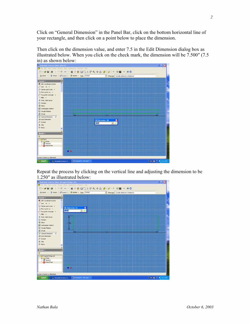
Click on “General Dimension” in the Panel Bar, click on the bottom horizontal line of your rectangle, and then click on a point below to place the dimension. Then click on the dimension value, and enter 7.5 in the Edit Dimension dialog box as illustrated below. When you click on the check mark, the dimension will be 7.500″ (7.5 in) as shown below:
Repeat the process by clicking on the vertical line and adjusting the dimension to be 1.250″ as illustrated below:

Nathan Bala October 6, 2003
3
Right click your mouse and choose done. Right click again and choose Isometric. Your screen must now look like this:
Now click on the arrow beside Sketch in the title area of the Panel Bar and choose Features. Your screen would look like this:
The next screenshot illustrates what you will see when you click on features.
Nathan Bala October 6, 2003
4
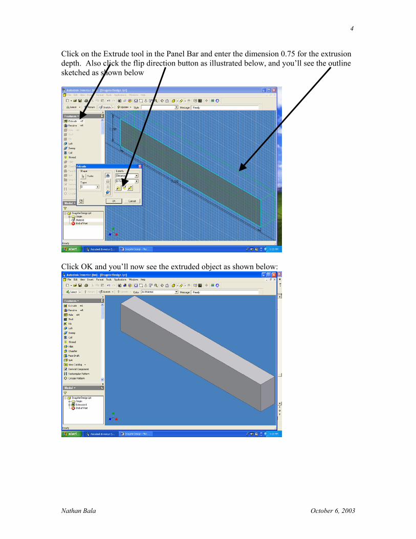
Click on the Extrude tool in the Panel Bar and enter the dimension 0.75 for the extrusion depth. Also click the flip direction button as illustrated below, and you’ll see the outline sketched as shown below
Click OK and you’ll now see the extruded object as shown below:

Nathan Bala October 6, 2003
5
Right click on the graphics window and select New Sketch as illustrated below:
Your screen should now look like this:

Nathan Bala October 6, 2003
6
Click on the “Look At” tool in the Standard tool bar.
Then click on the front face of the extruded object. You’re now seeing the object normal to that face as illustrated below:

Nathan Bala October 6, 2003
7
Now click on the “Point, Hole Center” tool in the Panel Bar and then click on the object about 0.25″ from the bottom edge (this should not be a problem if you remembered to set the grid spacing to 0.25″ in the initial Tools “Document Settings” Sketch option) as illustrated below:
Repeat for the left vertical edge too as shown below:

Nathan Bala October 6, 2003
8
Then click on the General Dimension tool in the Panel Bar. Click on bottom of the horizontal line, the center point location (+), and then the right side. You’ll see the distance of this point from the bottom as illustrated below:
Click on the dimension value, and in the Edit Dimension dialog box, enter the value 0.156″ and then click the check mark. Repeat the process from the right side edge and make sure the value is 1.5″ as illustrated below:

Nathan Bala October 6, 2003
9
Your screen should look like this: For the front the distance of the hole for the axle is only 1.250″ but the vertical hole distance must remain 0.156″ as before.
Now right click on the graphics window and select Isometric View. Your screen should look like this:

Nathan Bala October 6, 2003
10
Again, click on the arrow beside Sketch and select Features as shown below:
Now click on the “Hole” tool in the Panel Bar and enter the diameter of your bushing. To change the dimension to your designed size, click over the dimension in the diagram and change the value. Also select “Through All” from the termination list. Your screen will now look like this:

Nathan Bala October 6, 2003
11
When all the information has been entered correctly, click OK. The two holes for the axle are now in your 3D model as shown below:
As before, right click on your graphics window and select “New Sketch” as shown below:

Nathan Bala October 6, 2003
12
Then click on the “Look At” tool from the Standard Toolbar and select the right face and your screen should now look like this:
Like before, click on “Point, Hole Center” in the Panel Bar and select a point close to the center of this face as shown below:
Nathan Bala October 6, 2003
13
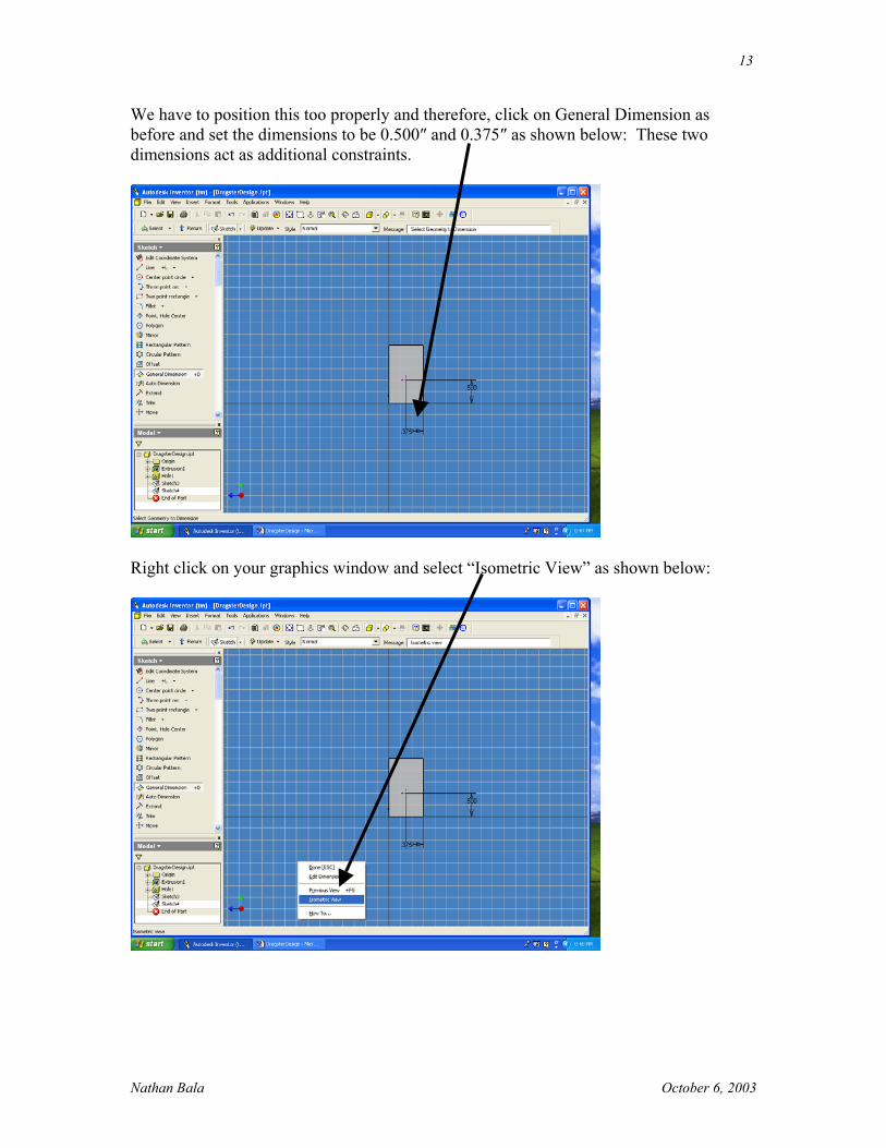
We have to position this too properly and therefore, click on General Dimension as before and set the dimensions to be 0.500″ and 0.375″ as shown below: These two dimensions act as additional constraints.
Right click on your graphics window and select “Isometric View” as shown below:

Nathan Bala October 6, 2003
14
Your screen must now look like this: Furthermore, click on the arrow beside Sketch like before and select Features.
Click on “Hole” in the Panel Bar and enter the dimensions from your design sheet (say 0.391″ for the diameter and 2.5″ for the depth of the hole. You can see the outline as shown below:

Nathan Bala October 6, 2003
15
If you’re satisfied, click OK and you should see this:
Finally, we need to cut the angle on the dragster. Right click on the graphics window and select “New Sketch” as shown below:

Nathan Bala October 6, 2003
16
As before, click on “Look At” from the Standard toolbar and click on the front face. You should now see this:
Click on the “Line” tool in the Panel Bar and draw a line about 0.250 from the bottom left hand corner (look for the coincident symbol) of the rectangular extruded object. Stretch the line to the upper right hand corner of the object, look for the coincident symbol and click OK. Your screen should look like this:

Nathan Bala October 6, 2003
17
Click on “General Dimension” in the Panel Bar. Click on the lower left corner of the object and the intersection of the inclined line & the vertical line, and then click to the left. You will find the dimension displayed and in the dimension dialog box, enter 0.250″. You should see the incline as a deep purple color now as illustrated below:
Click on the graphics window and select Isometric View as before.

Nathan Bala October 6, 2003
18
Your screen should look like this. Next, click on the arrow next to the Sketch in the title area and select “Features” as shown below:
Click the “Extrude” tool in the panel bar. Click the upper half above the incline because this is the material you wish to cut off. This area will turn a dark shade as shown below. Choose the “Cut” button and you will see a preview as shown below (the depth must be 0.75″ as before):

Nathan Bala October 6, 2003
19
Click OK and your part (dragster body) will now look like this:
From this point on, you’re on your own. Try to get the shape of your own design of the dragster using your sketch. Good luck and have fun!