Sub Title Author 渡部, 一郎(Watanabe, Ichiro)
14
Title Experimental study on radial turbine, with special reference to the influence of the number of impeller blades on performance characteristics Sub Title Author 渡部, 一郎(Watanabe, Ichiro) 安藤, 亨(Ando, Toru) Publisher 慶応義塾大学藤原記念工学部 Publication year 1959 Jtitle Proceedings of the Fujihara Memorial Faculty of Engineering Keio University Vol.12, No.45 (1959. ) ,p.55(1)- 67(13) Abstract Experiments were conducted to ascertain the influence of the number of impeller blades on the performance characteristics of a radial turbine. Thus, impellers fitted with 4, 8, 16, 24 and 32 blades respectively were employed, and the radial turbine was driven by compressed air delivered from Roots blowers. Besides usual measurements of pressures and temperatures, the flow directions as well as the magnitudes of the absolute velocities at the entrance of the impeller were measured by a yaw meter. The following results were obtained. (1) The optimum number of impeller blades of a radial turbine is not less than that of a centrifugal compressor. (2) In regions of maximum overall adiabatic effciencies, the relative velocities at the entrance of the impeller decline rotationwise by the angles 20-30 degrees. Notes The twentieth anniversary memorial volume Genre Departmental Bulletin Paper URL http://koara.lib.keio.ac.jp/xoonips/modules/xoonips/detail.php?koara_id=KO50001004-00120045 -0001 Powered by TCPDF (www.tcpdf.org)
Transcript of Sub Title Author 渡部, 一郎(Watanabe, Ichiro)
Title Experimental study on radial turbine, with special reference to the influence of the number ofimpeller blades on performance characteristics
Sub TitleAuthor 渡部, 一郎(Watanabe, Ichiro)
安藤, 亨(Ando, Toru)Publisher 慶応義塾大学藤原記念工学部
Publication year 1959Jtitle Proceedings of the Fujihara Memorial Faculty of Engineering Keio
University Vol.12, No.45 (1959. ) ,p.55(1)- 67(13) Abstract Experiments were conducted to ascertain the influence of the number of impeller blades on the
performance characteristics of a radial turbine. Thus, impellers fitted with 4, 8, 16, 24 and 32blades respectively were employed, and the radial turbine was driven by compressed airdelivered from Roots blowers. Besides usual measurements of pressures and temperatures, theflow directions as well as the magnitudes of the absolute velocities at the entrance of theimpeller were measured by a yaw meter.The following results were obtained. (1) The optimum number of impeller blades of a radialturbine is not less than that of a centrifugal compressor. (2) In regions of maximum overalladiabatic effciencies, the relative velocities at the entrance of the impeller decline rotationwise bythe angles 20-30 degrees.
Notes The twentieth anniversary memorial volumeGenre Departmental Bulletin PaperURL http://koara.lib.keio.ac.jp/xoonips/modules/xoonips/detail.php?koara_id=KO50001004-00120045
-0001
Powered by TCPDF (www.tcpdf.org)

Experimental Study on Radial Turbine, with Special
Reference to the Influence of the Number
of Impeller Blades on Performance Characteristics. (Received Dec. 12, 1959)
Abstract
Ichiro WATANABE*
Toru ANDO**
Experiments were conducted to ascertain the influence of the number of impeller blades on the performance characteristics of a radial turbine. Thus, impellers fitted with 4, 8, 16, 24 and 32 blades respectively were employed, and the radial turbine was driven by compressed air delivered from Roots blowers. Besides usual measurements of pressures and temperatures, the flow directions as well as the magnitudes of the absolute velocities at tte entrarce of the impeller were measured by a yaw meter.
The following results were obtained. (1) The optimum number of impeller blades of a radial turbine is not less than that of a centrifugal compressor. (2) In regions of maximum overall adiabatic effciencies, the relative velocities at the entrance of the impeller decline rotationwise by the angles 20--30 degrees_
I. Introduction
Radial turbines are widely used in every field, for instance, as small gas turbines1)
for fire pump drive as well as the exhaust turbines for superchargers. 2) Literatures. concerning the performance characteristics of a radial turbine are already published by several authors, i.e. W.T. Nuell, 3 ) L.R. Wosika,0 P.F. Martinuzzi,5) while in Japan. literatures by Yasuo Mori,6 ) Nagao Mizumachi,7) Masanobu Sekine8) are available~
* iJt -tfl3 - 1!~ Dr. Eng., Professor at Keio University ** !i3. Hi Jjl= Lecturer at Keio University 1) A. D. Zakarian, R. R. Peterson; Auto. Industries, Vol. 104. No. 8 (1951-9-15)
p. 34; Mech. Engg., Vol. 74, No. 1 (1952), p. 26. 2) Ot"l Engine and Gas Turbine, Vol. 22, No. 260 (1955-2) p. 395; Vol. 23, No. 263
( 1955-5), p. 32; Vol. 22, No. 262 (1953-4), p. 4 71. 3) W. T. Nuell: Trans. ASME, Vol. 74 (1952-5), p. 499. 4) L. R. Wosika: Trans. ASME, Vol. 74, (1952-11), p, 1337. 5) P. F. Martinuzzi: Trans. ASME, Vol. 74 (1952-7), p. 663 6) Y. Mori: Trans. japan Soc. Me,h. Engrs., Vol. 20, No. 96 (1954), p. 552; Vol. 21.
No. 109 (1955), p. 679. 7) N. Mizumachi: Report Inst. Industrial Science, Tol.yo Univ., Vol, 8, No.1
(1958-12), 8) M. Sekine et al: Preprz"nt 33rd Annual ~Melting, J.S.M.E. (1956-4-3).
( 1 )
56 Ichiro WATANABE and Toru ANDO
Although the problems concerning the number of impeller blades of a radial turbine are dealt with by H.R. Cox 9> to some extent, they are not yet completely solved, and so the present authors made an experimental investigation using an
experimental radial turbine. It has been the general concept that smaller number of impeller blades may be available in the case of radial turbine than in the case of centrifugal compressor, because of the expansion flow process having less pos
sibility to stall, and the present authors also expected the same results. Application of the formula for optimum number of impeller blades of a centrifugal compressor
by L. R. Wosika z= 10+0.75D, where D is the impeller diameter in inches, to the present case (D = 150 mm) yields z = 14.44. Therefore, we conducted experiments with impellers having 16, 8 and 4 blades and found the optimum number of impeller blades far exceeding the tested numbers. Thus the authors prepared two more impellers with 24 and 32 blades respectively, and the experiments were carried out over again for all the five impellers, using compressed air from Roots blowers.
The results of the present investigation were that the optimum number of impeller blades for radial turbine is not less than that for centrifugal compressor. Further, in these experiments, the absolute velocities as well as the flow directions of the air just entering the impeller were measured by a yaw meter, and some interesting results were obtained, which will be shown later.
II. Experimental Apparatus and the Method
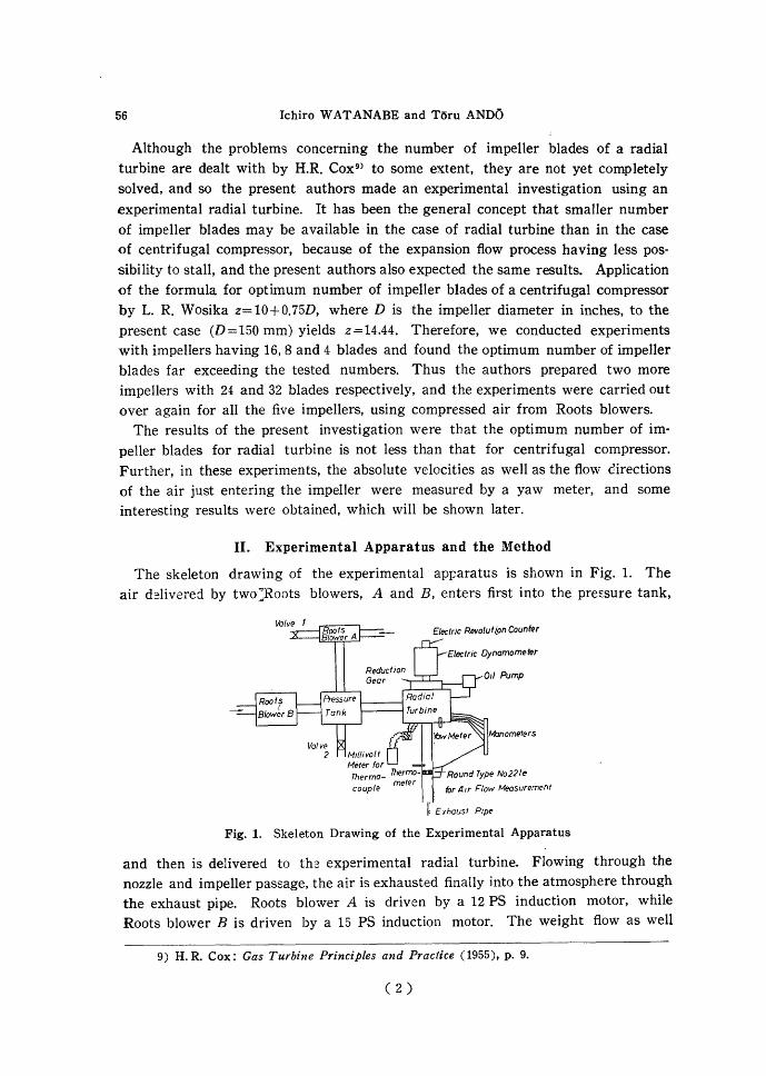
The skeleton drawing of the experimental apparatus is shown in Fig. 1. The air d~livered by two :Roots blowers, A and B, enters first into the pre£sure tank,
/11anometers
for At r Flow Measurement
r Exhausf Ptpe
Fig. 1. Skeleton Drawing of the Experimental Apparatus
and then is delivered to th~ experimental radial turbine. Flowing through the nozzle and impeller passage, the air is exhausted finally into the atmosphere through the exhaust pipe. Roots blower A is driven by a 12 PS induction motor, while Roots blower B is driven by a 15 PS induction motor. The weight flow as well
9) H. R. Cox: Gas Turbine Principles and Practice ( 1955 ), p. 9.
c 2)

Experimental Study on Radial Turbine 5T
as the pressure of the air enteting the radial turbine may be controlled by the two valves 1 and 2. Round type nozzle for air flow measurement is fitted to the eJChaust pipe as shown. The radial turbine is coupled to the 2 PS electric dynamometer through a reduction gear, the reduction ratio of which is 1/3. 4. Thus,. the electric dynamometer indicates the horsepower difference between the shaft horsepower of the turbine and the lost horsepower in the reduction gear. Lubricating oil is fed to the turbine and to the reduction gear by a gear pump by a 1/20 PS electric motor. A yaw meter of 4 mm diameter is installed at the exit of the nozzle (just upstream to the entrance of the impeller) as shown in Fig. 4, and the absolute velocities as well as the flow directions of the air entering the impeller were measured.
The experimental radial turbine used is shown in Fig. 2. Five impellers fitted with 32, 24, 16, 8 and 4 blades were machined from aluminium casting, and these impellers were of 150 mm outside diameters and 90 mm inside diameters as shown in Fig. 3. Common exducer having 8 blades was employed for these five impellers, the exit angle of the exducer being 45 degrees corresponding to the design weight flow G=0.15 kg/s and impeller revolutions n = 6000 r. p. m .. The inlet flow area for the turbine and the exit flow area from the turbine amount to 0.003 m2 and 0.00636 m2 respectively, and the nozzle used is, as shown in Fig. 2, of parallel wall type without guide vanes, the outside diameter and the inside diameter of which are 220 mm and 160 mm respectively.
Observations of pressures and temperatures were made at the sites shown Fig. 2. Experimental Radial Turbine
in Fig. 4. Thus, pressures Pt--P5 and temperatures lt,...,ls within the scroll and pressures p6--p9 and temperatures t6--t9 along the impeller passage were measured, the latter pressures and temperatures being observed from the casing by means of water manometers and thermocouples. P6 and t6 correspond to the pressure and and temperature at the inlet to the impeller respectively, while pg and t9 denote those just at the exit end of the exducer blades. The location at which the yaw meter is fitted is also shown in the figure. In the exhaust pipe, the pressure and temp2!rature upstream to the nozzle Pto, ito as well as the down stream pressure
( 3)

58 Ichiro WATANABE and Toru ANDO
Pu were measured. Further, the atmospheric pressure Pa and temperature ta were read in each observation. In the above-mentioned observations, pressures were measured by mercury or water manometers, while temperature observations were made by means of thermocouples and thermometers.
Fig. 3. Impellers used in the Experiment
(C) (b)
Fig. 4. Sites for Observations of Pressures, Temperatures and Flow Directions
As to the experimental method, the openings of the valves 1 and 2 were so adjusted that the weight flow of air through the radial turbine might remain constant, thus the impeller revolutions were varied from 4000 r.p.m. to 11000 r.p.m. by varying
(4)

Experimental Study on Radial Turbine 59
the load of the electric dynamometer to take observations at every 1000 r. p.m. interval.
III. Experimental Results and Considerations
The observed pressures were corrected to the standard atmospheric condition by the formula P=P0(760/Pa 0), where p0 denotes the observed pressure when the bar· ometric pressure corresponds to Pa0, and p means the pressure when the barometric pressure is standard, i.e. 760 mm Hg. As to the temperatures, no correction was made.
The evaluation of overall adiabatic efficiency r;0 of the turbine was made by the following expression;
( 1 )
where L: turbine output PS, G: weight flow of air kg/s, T1 : absolute air tem· perature at nozzle inlet o K, Pt> p9 : static pressurEs at nozzle inlet and exducer exit respectively, w1 : absolute velocity of air at nozzle inlet m/s, and Wg : the theoretical absolute velocity of air at exducer exit calculated from the measured weight flow of air G assuming adiabatic isentropic expansion from P1 to pg.
The slip coefficient of impeller may be defined as follows,
( 2)
where f1 : slip coefficient of impeller, p6 , T6 : static pressure and absolute temper· ature of air at the impeller inlet, w6 : absolute velocity of air at the impeller inlet, a6 ; tangential component of absolute velocity of air at the impeller inlet, and u6 :
peripheral velocity at the impeller inlet (outside diameter of the impeller). In the above expression, w6 may be read from the yaw meter observations, and values of the theoretical absolute velocities of air at exducer exit w9 may be derived from the assumption that the expansion p6 to P9 is adiabatic and reversible.
Fig. 5 represents the relation between overall adiabatic efficiency r;0 and impeller revolutions per minute n for the case G = 0.1080 kg/s, the number of impeller blades being taken as parameters. This belongs to the smaller weight flow regions, and as is clear from the figure, the highest value of r;0 is obtained for the case z=32 at higher revolutions, and r;0 becomes worse as z decreases. In the regions n=7000 ---8000 r.p.m., it is seen that the cases z= 16, 24 and 32 are favourable. Figs. 6 and 7 represent the relations between r;0 and n in the case G=0.1251 kg/s and G=0.1457 kg/s respectively, i.e. the cases of medium and larger weight flows. In these cases, r;0 becomes better at z=8, 16 and 24, while r;0 decreases at z=32. It is con· ceivable that this is due to the increment of frictional losses within the impeller
(5)

60 Ichiro WATANABE and Toru ANDO
~
~ 60 c: <I> "i:j ;::: lU 50 . -~ 0 ~ -~ 40 "tJ -q:
""£ 30 :::..
0
20 4 6 8
Marks No.cf blades Z
• 32 X 24 a 16 0 8 8 4
10 12X/0 1
Impeller Revolutions n rpm
Fig. 5. Relation between '1/o and n (G=0.1080 kg/s)
't'Jo c: .~
Marks No.of blades Z
• 32 X 24 a 16 0 8 8 4
/~ ~sof· .. Z-4
~40 :.. 0
304 6 ~ 10
Impeller Revolutions n rpm
Fig. 7. Relation between r;0 and n (G=0.1457 kg/s)
Marks No.ofblades Z
• 32 X 0 [J
8
24 16 8 4
Z=32
20~---L--~~---L--~
4 6 8 10 t2xto•
[mpeller Revolutions n rpm
( 6)
Fig. 6. ~elation between r;0 and n (G=0.1251 kg/s)

Experimental Study on Radial Turbine 61
passage. The value r;0 is somewhat low in every case, which may be attributed
to the losses in the reduction gear.
It has been considered generally that the optimum number of impeller blades
will be less than that for centrifugal compressor on account of expansion flow
process. Dr. B. Eckert, whom one of the authors had met in his journey, said to
him that the optimum number of impeller blade for the present case would be
around z=17, and Dr. W. T. Nuell in Garrett Corp. showed him that the optimum number Zopt might be determinEd frcm the criterion that Zopt=8 for DdDt =2 and Zopt =12 for DdD1 =1.5. For the present case, in which DdDt =150/90=1.67, we have Zopt = 10 according to Nuell's criterion, but the results already given in Figs. 5, 6 and 7 show that Zopt is greater than the criterion. As stated previously, the optimum number of impeller blades for centrifugal compressor Zopt = 14.44, and so we find it necessary to adopt a larger value of Zopt for the radial turbine than for the
centrifugal compressor when the weight flow of air is relatively small, and further to adopt Zopt for the radial turbine at least Equal to Zopt for the centrifugal com
pressor for a large weight flow.
Next, as we are acquainted with the magnitude and direction of the absolute velocity w6 at the inlet to the impeller, we are now able to check from Figs. 5, 6 and 7 whether or not the relative velocity at the impeller inlet wr6 enters radially inward along the blades at points of maximum overall adiabatic efficiencies r;0•
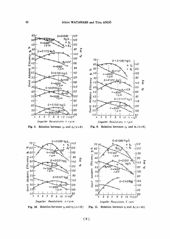
As is seen from Fig. 4 (b), the magnitudes and directions of w6 were measured at the region where the influence of the scroll entrance is considered negligible. From the observed magnitudes of w6, angle a6 and peripheral velocity u6, we are able to find values of Wr6 and 96 from the velocity diagram as shown in Fig. 4 (b). Thus it is possible to check whether 96 amounts to 90 degrees (radially inward) or not. The results for z=4, 8, 16, 24 and 32 are shown in Figs. 8, 9, 10, 11 and 12 respectively. From these results we have: 96 =104°--122° for z=4 (Fig. 8), 96=108°--120° for z=B (Fig, 9), 96= 108°-121 o for z=16 (Fig. 10), 96 =112°--122° for Z=24 (Fig.11) and 96= 110°--128° for z=32 (Fig. 12). Then we find that 96 is larger than 90°, and we are to choose the value of 96 around 110°-120° in the design of a radial turbine. Also we see that the actual values of 96 do not vary largely as the number of impeller blades z changes, though 96 for z=32 is slightly larger than in the other cases. The reason why the values of 96 for maximum r;0 amount to 110°--120° instead of 90° is not clear, but is is conceivable that the problem is intimately related to the flow pattern, especially the separation of flow within the impeller passage.
The relation between the shaft horsepower of the radial turbine and the impeller revolutions n is shown in Figs. 13, 14, 15, 16 and 17 for the case z=4, 8, 16, 24 and :32, respectively, the weight flow G being selected as parameter. From these .diagrams, it is seen that the optimum n for maximum shaft horsepower lies ~orne· ·what higher than that for maximum r;0•
( 7)
62 Ichiro WATANABE and Toru ANDO
14 ()
120
100
ao 0'1 C!.r "tJ
140 "' Q)
120
TOO
80
140
120
TOO
120
·roo 80
140
100 8 9 I 0 /JX/0 3
Impeller RevolufJons n rpm
Fig. 8. Relation between r;0 and e6 (z =4)
G =0.1080 kgfs 14 0
120
100
80
140
120
100
ao 140
120
100 '---__L_---1----1.-L----l-----'----'----' 8 0
5 6 7 8 9 J 0 11 X103
Impeller Revolutions n rpm
0) <II
"\:)
~
Fig. 10. Relation between r;0 and 06 (z = 16)
G = 01080 kgjs
G=0./080 kg/s 0 0 7() ]140
l( 6& 120
!00
80 0'1
T4 0 Q, 1::1
T20 ~ ·~
2 TOO -~
80 "tJ '<:{
-.::: 160 ClJ 140 :::..
0
120
~~~~-~~---~-~~too 5 6 7 8 9 TO 11 X 10~
Impeller Revolutions n ~om Fig. 11. Relation between 1lo and 06 (z=24)
(8)

Experimental Study on Radial Turbine 63
50
60
50·
70
50.
I~ 0
120
100
80
14 0
120
100
80
160
140
·120
100
/40
120
100
120
100
~ __::;.:G-""""'(!)o...;;:-] 1 6 0
0 I 140 x--x : -x- 1 e,- ,IQ~x-
n •!1000~Pm .4'0
304~~5--6+-~~7~~8--9~~,0~,~,-x~T0180
Impeller Revolutions n rpm
Fig. 12. Relation between 110 and
Os(Z=32)
G =0 1561 kg/s
10
6 8 10 12·X 10~
Impeller Revolutions n rpm
Fig. 13. Relation between output and n (z=4)
V) Q6. q.
a 0.4 8
G=01561k9/s
q.7251 k9js;
0'-------L------L----L------' 4 6 8. 10 12 X 10"
Impel/ Revolutions n rpm
Fig. 14. Relation between output and n (z =8)
( 9)

64 Ichiro WATANABE and Toru ANDO
12
1.0
Q1080k9/s
D L----L----~--~--~ 4 6 8 10
Impeller Revolutions n rpm
Fig. 15. Relation between output and n (z=16)
V) Q
1.4
12
6 8
/G •0.1457 kg/s
V)
Cl.
:; Q.
"5 0.4 . 0 O.tOBOkgfs
0.2
04 6
impeller Revolutions n rpm
Fig. 16. Relation between output and n (z=24)
G =0.7561kgjs
10
Impeller Revolutions n rpm
Fig. 17. Relation between output and n (z = 32)
(10)
Experimental Study on Radial Turbine 65
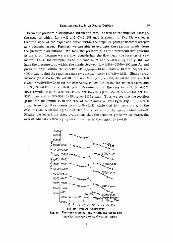
From the pressure distributions within the scroll as well as the impeller passage, the case of which for z=32 and G=0.1251 kg/s is shown in Fig. 18, we learn that the slope of the expansion curve within the impeller passage becomes steeper as n becomes larger. Further, we are able to evaluate the reaction grade from the pressure distributions. We took the pressure P2 as the representative pressure in the scroll, because we are now considering the flow near the location of yaw meter. Thus, for example, as to the case z=32 and G=0.1251 kg/s (Fig. 18), we have the pressure drop within the nozzle L1Pn=P2-P6 =10850-10560=290 mm Aq and pressure drop within the impeller L1Pi=P6-Pg=10560-10420=140 mm Aq for n=
4000 r.p.m. to find the reaction grade r=L1Pd(L1Pn+L1Pi)=140/430=0.326. Similar evaluations yield r=140/465=0.301 for n=5000 r.p.m., r=190/500=0.380 for n=6000'
r.p.m., r=250/555=0.450 for n=7000 r.p.m., r=295/615=0.480 for n=SOOO r.p.m. and r=330/690=0.478 for n=9000 r.p.m.. Examination of the case for z=8, G=0.1251
kg/s reveals that r=290/710=0.4085 for n=7000 r.p.m., r=320/710=0.451 for n=
8000 r.p.m. and r=385/900=0.428 for n=9000 r.p.m.. Thus we see that the reaction grade for maximum r;0 in the case of Z=32 and G=0.1251 kg/s (Fig. 18) (n=7300
r.p.m. from Fig. 12) amounts to r=0.450--0.480, while that for maximum r;0 in the case of z=8, G=0.1251 kg/s (n=8500 r. p.m.) lies within the range r=0.451--0.428.
Finally, we learn from these evaluations that the reaction grade which makes the overall adiabatic efficiency r;0 maximum lies in the region 0.43,._,0.48.
(11)

66 Ichiro WATANABE and Toru ANDO
Fig. 19 shows the relation between the slip coefficient IL evaluated by Eq. (2) and the impeller revolutions n indicating that IL decreases as n becomes larger. Fig. 19 corresponds to the case of Fig. 5 and from this figure we see also that IL
for z= 16 and 24 has a higher value than for the other cases.
Marks No.of blades Z •. 32 X 24 e 16
0 8 I}. 4
~ 60.
~ t:
50 -16 llJ <:;
.;:: 'Q; 4 0 ;: -32 ()
<...>
Q.
~~ 30
20 4 5
Impeller Revolutions n rpm Fig. 19. Relation between p. and n (G=0.1080 kg/s)
IV. Conclusions
Ji'rom the above-mentioned results and considerations, we reach the following con
clusions. (1) The optimum number of impeller blades for the radial turbine is not ·less
than that for the centrifugal ccmpressor. The optimum number of impeller blades for the radial turbine is comparable with that for the centrifugal compressor for the larger weight flow, but it is preferable to select the former larger than the latter for the smaller weight flow.
(2) The inflow direction of the relative velocity at the impeller inlet 96 for the cases of maximum overall adiabatic efficiencies is not purely radial (96 =90°), but 96
.amounts to around ll0°""l20°, i.e. the inflow direction decline rotationwise relative to the impeller at every number of impeiler blades. Strictly speaking, 96 is somewhat larger in the case z=32, that is 96 =121 o,....,128°.
(3) The impeller revolution which makes the shaft horsepower maximum is larger than that for maximum r;o at every number of impeller blades and weight flow.
(4) The reaction grade corresponding to maximum overall adiabatic efficiency
7Jo amounts to about 0.43--0.48.
( 5) The slip coefficient of impeller IL decreases as impeller revolutions increase for every number of impeller blades.
(12)

Experimental Study on Radial Turbine 67
The present investigation was performed by the authors with the cooperation of the Ishikawajima Heavy Industry Co., and the present authors are much indebted to Messrs. 0. Nagano, Y. Shoda, M. Matsuno and M. Sekine of the company. The expriment was conducted under the financial aids from the Ministry of Education, Japanese Government. They wish to express their heartfelt thanks for the cooperations of Messrs. K. Fujie, I. Ariga, K. Sasamura K. Takewari, R. Toyota, T. Yoshizawa, S. Kawashima, Y. Kojima, T. Tsubone, Y. Murata, M. Yamamuro and T. Nakahara who were students at that time and also Mr. T. Koitabashi; assistant.
(13)