STYLE #: 159020 Maximum Height Maximum Field Rating Tree ...
20
Instruction Manual 15’ LADDER STAND MODEL #: PL200GW STYLE #: 159020 For parts call our Customer Service Center at 800-345-6007 Business Hours: 8:00 am to 5:00 pm CST © 2020 RETI All Rights Reserved | 34517 REV2 | 12/01/2020 | C/N: 34480 PARTICIPATING MEMBER PRODUCT MEETS INDUSTRY STANDARDS RECOGNIZED BY Maximum Height 15’ 4” to seat Wear Your Harness! Maximum Field Rating 300 lbs Tree Diameter Range 12" to 20" www.standsafety.com/r3 WATCH THIS SAFETY VIDEO BEFORE USING! YOU MUST READ ALL WRITTEN INSTRUCTIONS AND WATCH THIS SAFETY VIDEO BEFORE USING! ! ATTENTION OR Scan the QR code with your smart phone, tablet or similar device. Type the website address into your web browser to view an important safety video before using this product. Scan or Visit LADDER STAND SAFETY FALLS FROM HEIGHTS MAY RESULT IN SERIOUS INJURY OR DEATH! WARNING! FALL HAZARD!
Transcript of STYLE #: 159020 Maximum Height Maximum Field Rating Tree ...
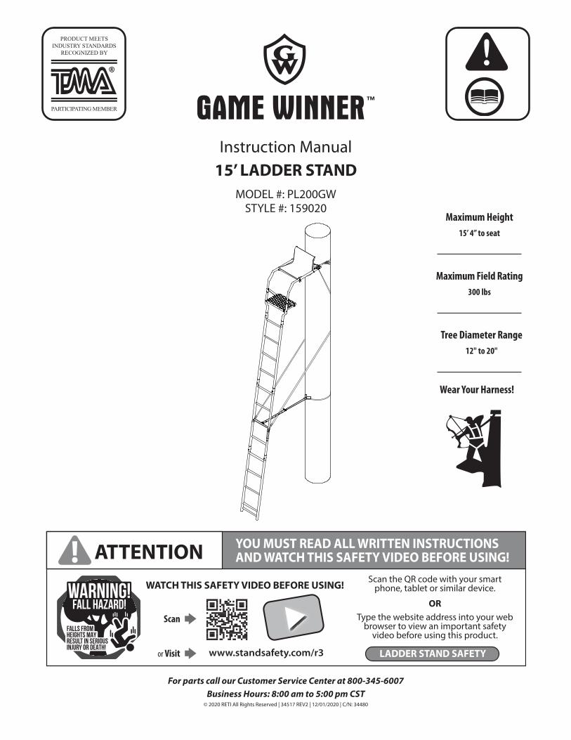
Instruction Manual15’ LADDER STAND
MODEL #: PL200GWSTYLE #: 159020
For parts call our Customer Service Center at 800-345-6007Business Hours: 8:00 am to 5:00 pm CST
© 2020 RETI All Rights Reserved | 34517 REV2 | 12/01/2020 | C/N: 34480
GAS/OILRATIO
50:1
PARTICIPATING MEMBER
PRODUCT MEETS INDUSTRY STANDARDS
RECOGNIZED BY
Maximum Height 15’ 4” to seat
Wear Your Harness!
Maximum Field Rating300 lbs
Tree Diameter Range12" to 20"
www.standsafety.com/r3
WATCH THIS SAFETY VIDEO BEFORE USING!
YOU MUST READ ALL WRITTEN INSTRUCTIONS AND WATCH THIS SAFETY VIDEO BEFORE USING!! ATTENTION
OR
Scan the QR code with your smart phone, tablet or similar device.
Type the website address into your web browser to view an important safety
video before using this product.
Scan
or Visit LADDER STAND SAFETY
FALLS FROMHEIGHTS MAYRESULT IN SERIOUSINJURY OR DEATH!
WARNING!FALL HAZARD!

Instruction Manual : 15’ LADDER STAND
2
TABLE OF CONTENTS
Warranty Information ............................................................................................................................................................................................................ 2
Warnings ................................................................................................................................................................................................................................. 3-4
Parts List .................................................................................................................................................................................................................................. 5-7
Tools Required .......................................................................................................................................................................................................................... 8
Hardware .................................................................................................................................................................................................................................... 8
Product Diagram...................................................................................................................................................................................................................... 9
Finished Ladder ......................................................................................................................................................................................................................10
Assembly Instructions .................................................................................................................................................................................................. 11-14
Installation and Use Instructions .............................................................................................................................................................................. 16-18
Inspections and Maintenance/Notes Page ..................................................................................................................................................................19
Note: Before beginning assembly of product, make sure all parts are present. Compare parts list with package and hardware contents. If any part is missing or damaged do not attempt to assemble the unit. Contact customer service for replacement parts.
WARRANTY
RETI offers a one year warranty for all components of the treestand. These warranties apply to the original owner with a proof of purchase. These warranties begin on the date of purchase by the first retail consumer and continue for the period specified above. These warranties apply to products that are not modified, abused or used in a manner that deviates from the product’s intended usage. Minor fading in color is normal and is not covered by warranty. Any corrosion of painted surfaces that occurs as a result of paint being removed or damaged is also not covered by warranty. RETI offers no other warranty expressed or implied. Products for which warranty work has been approved must be sent directly to RETI and performed by RETI. To obtain warranty service and/or replacement instructions, you must obtain prior approval from RETI before shipping your package to us by calling our customer service department at 800-345-6007 or by writing to: Ardisam, Inc., P.O. Box 755, 1160 Eighth Avenue, Cumberland, WI 54829 for a return material authorization number (RMA#). All items must be shipped prepaid. RETI will, at no charge, repair or replace, in RETI’s sole discretion, any product that satisfies the conditions stated above. RETI retains the right to change models, specifications and price without notice.
This equipment has been manufactured under strict quality and safety guidelines. As with any equipment of this type, full understanding of the instructions and its use is mandatory and imperative for the safety of its user. RETI is not responsible for any damages or injuries sustained due to improper use or modification of any of its products, or resulting from any use which deviates from the product’s intended usage. RETI is not responsible for any injuries sustained due to failure to read and adhere to the instructions for use. Any misunderstanding or questions regarding the products of their use should be directed to RETI prior to any use. It is the owner’s sole responsibility to inspect the product regularly for damage, improper installation, or conditions that could jeopardize the ultimate safety of the product. Failure to use or improper use of a Fall Arrest System may result in serious injury or death. ALWAYS wear a Fall Arrest System while using this product. Owner is responsible to understand and follow product field weight rating and must never exceed maximum weight rating. RETI is not responsible for any malfunction or injury resulting from normal wear and tear, damage caused by improper use, improper maintenance, negligence or accidents. This product, if used safely as intended, will provide trouble free service for the useful life of the product. We hope you will enjoy the quality of our products for years to come, and have a safe hunt.
PAGE
Instruction Manual : 15’ LADDER STAND
3
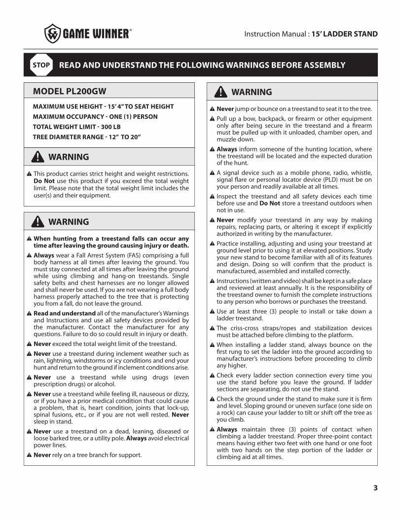
MODEL PL200GW
MAXIMUM USE HEIGHT - 15’ 4” TO SEAT HEIGHT
MAXIMUM OCCUPANCY - ONE (1) PERSON
TOTAL WEIGHT LIMIT - 300 LB
TREE DIAMETER RANGE - 12” TO 20”
WARNING
This product carries strict height and weight restrictions. Do Not use this product if you exceed the total weight limit. Please note that the total weight limit includes the user(s) and their equipment.
WARNING
When hunting from a treestand falls can occur any time after leaving the ground causing injury or death.Always wear a Fall Arrest System (FAS) comprising a full body harness at all times after leaving the ground. You must stay connected at all times after leaving the ground while using climbing and hang-on treestands. Single safety belts and chest harnesses are no longer allowed and shall never be used. If you are not wearing a full body harness properly attached to the tree that is protecting you from a fall, do not leave the ground.Read and understand all of the manufacturer’s Warnings and Instructions and use all safety devices provided by the manufacturer. Contact the manufacturer for any questions. Failure to do so could result in injury or death.Never exceed the total weight limit of the treestand.Never use a treestand during inclement weather such as rain, lightning, windstorms or icy conditions and end your hunt and return to the ground if inclement conditions arise.Never use a treestand while using drugs (even prescription drugs) or alcohol.Never use a treestand while feeling ill, nauseous or dizzy, or if you have a prior medical condition that could cause a problem, that is, heart condition, joints that lock-up, spinal fusions, etc., or if you are not well rested. Never sleep in stand.Never use a treestand on a dead, leaning, diseased or loose barked tree, or a utility pole. Always avoid electrical power lines.Never rely on a tree branch for support.
WARNING
Never jump or bounce on a treestand to seat it to the tree.Pull up a bow, backpack, or firearm or other equipment only after being secure in the treestand and a firearm must be pulled up with it unloaded, chamber open, and muzzle down.Always inform someone of the hunting location, where the treestand will be located and the expected duration of the hunt.A signal device such as a mobile phone, radio, whistle, signal flare or personal locator device (PLD) must be on your person and readily available at all times.Inspect the treestand and all safety devices each time before use and Do Not store a treestand outdoors when not in use.Never modify your treestand in any way by making repairs, replacing parts, or altering it except if explicitly authorized in writing by the manufacturer.Practice installing, adjusting and using your treestand at ground level prior to using it at elevated positions. Study your new stand to become familiar with all of its features and design. Doing so will confirm that the product is manufactured, assembled and installed correctly.Instructions (written and video) shall be kept in a safe place and reviewed at least annually. It is the responsibility of the treestand owner to furnish the complete instructions to any person who borrows or purchases the treestand.Use at least three (3) people to install or take down a ladder treestand.The criss-cross straps/ropes and stabilization devices must be attached before climbing to the platform.When installing a ladder stand, always bounce on the first rung to set the ladder into the ground according to manufacturer’s instructions before proceeding to climb any higher.Check every ladder section connection every time you use the stand before you leave the ground. If ladder sections are separating, do not use the stand.Check the ground under the stand to make sure it is firm and level. Sloping ground or uneven surface (one side on a rock) can cause your ladder to tilt or shift off the tree as you climb.Always maintain three (3) points of contact when climbing a ladder treestand. Proper three-point contact means having either two feet with one hand or one foot with two hands on the step portion of the ladder or climbing aid at all times.
READ AND UNDERSTAND THE FOLLOWING WARNINGS BEFORE ASSEMBLYSTOP

Instruction Manual : 15’ LADDER STAND
4
WARNING
WARNING
Always lean forward as you climb and attach your harness to the tree before securing the platform to the tree and stepping onto the platform.
Never exceed the stated maximum use height.
Do Not use this product until you have watched the safety video, understand it, and practiced the techniques for safe hunting discussed in this video. The video can be found with the QR code and/or URL shown on front cover of this manual.
Read and perform all inspection and maintenance tasks before each and every use. Replace any questionable components immediately with RETI original replacement parts.
Do Not crush tubing when tightening bolt assemblies! Identify and familiarize yourself with all parts before you start. Bolt identification chart can be found on the follow- ing page of the manual.
Double check assembly steps to be certain you have correctly assembled this product.
Never use any product that has not been maintained or inspected properly - Your life depends on it!
Replace any and all treestand straps every two years or when any signs of damage or wear exist before.
Always wear the appropriate footwear when using a ladder treestand. A good non-slip safety boot is import- ant to your personal safety. Be especially careful that boot laces do not get hooked on the stand or any of its components (tuck shoelaces into boots before climbing).
Only use approved RETI parts. Failure to do so may result in serious injury or death!
Instruction Manual : 15’ LADDER STAND
5
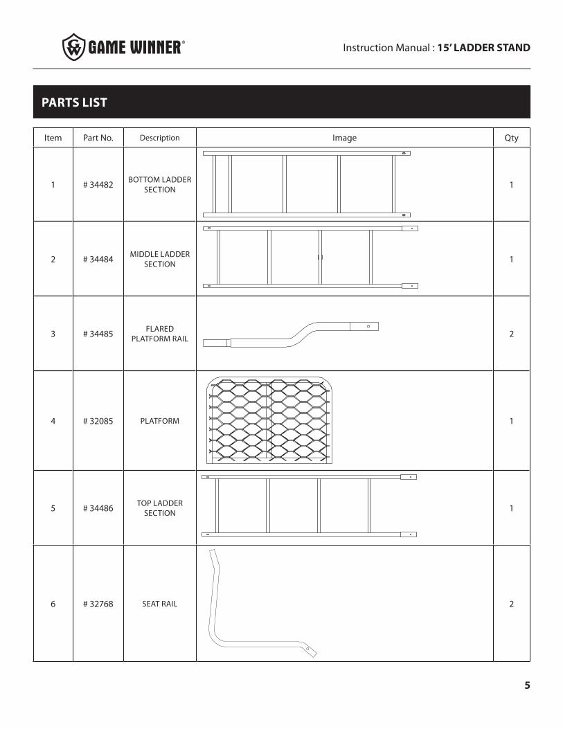
PARTS LIST
Item Part No. Description Image Qty
1 # 34482 BOTTOM LADDER SECTION 1
2 # 34484 MIDDLE LADDER SECTION 1
3 # 34485 FLARED PLATFORM RAIL 2
4 # 32085 PLATFORM 1
5 # 34486 TOP LADDER SECTION 1
6 # 32768 SEAT RAIL 2
Instruction Manual : 15’ LADDER STAND
6
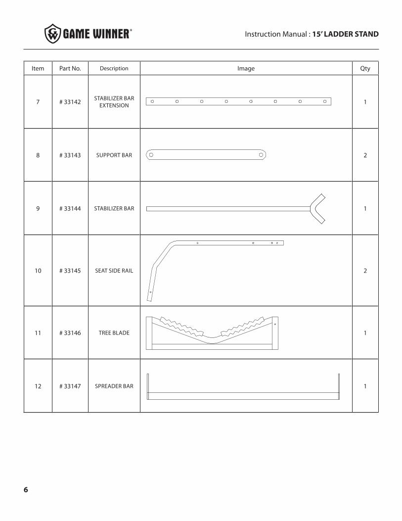
Item Part No. Description Image Qty
7 # 33142 STABILIZER BAR EXTENSION 1
8 # 33143 SUPPORT BAR 2
9 # 33144 STABILIZER BAR 1
10 # 33145 SEAT SIDE RAIL 2
11 # 33146 TREE BLADE 1
12 # 33147 SPREADER BAR 1
Instruction Manual : 15’ LADDER STAND
7
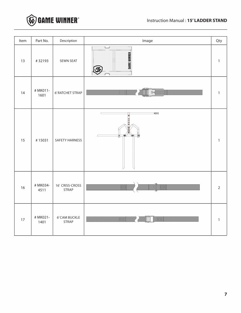
Item Part No. Description Image Qty
13 # 32193 SEWN SEAT 1
14 # MK011-1601
6’ RATCHET STRAP 1
15 # 15031 SAFETY HARNESS 1
16 # MK034-4511
16’ CRISS-CROSS STRAP 2
17 # MK021-1401
6’ CAM BUCKLE STRAP 1
Instruction Manual : 15’ LADDER STAND
8
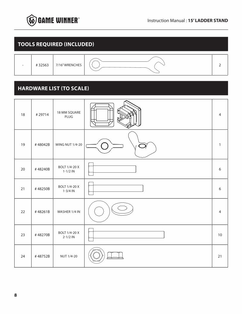
HARDWARE LIST (TO SCALE)
18 # 29714 18 MM SQUARE PLUG 4
19 # 48042B WING NUT 1/4-20 1
20 # 48240B BOLT 1/4-20 X 1-1/2 IN 6
21 # 48250B BOLT 1/4-20 X 1-3/4 IN 6
22 # 48261B WASHER 1/4 IN 4
23 # 48270B BOLT 1/4-20 X 2-1/2 IN 10
24 # 48752B NUT 1/4-20 21
- # 32563 7/16” WRENCHES 2
TOOLS REQUIRED (INCLUDED)
Instruction Manual : 15’ LADDER STAND
9
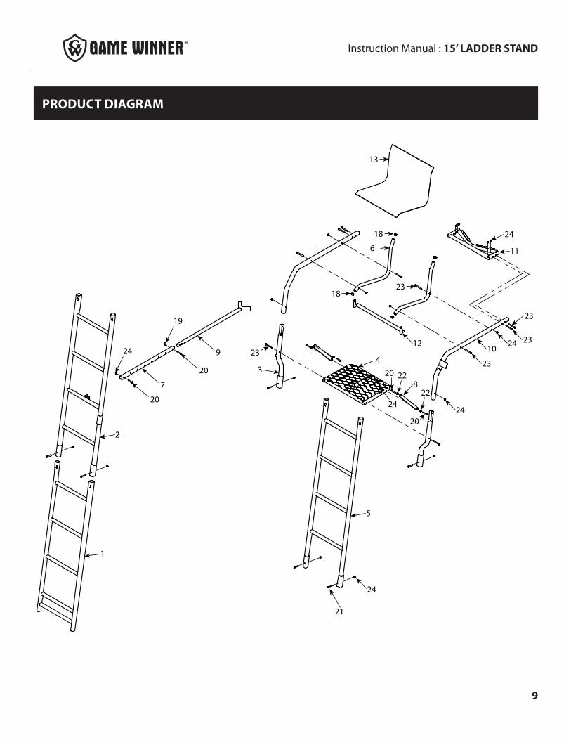
PRODUCT DIAGRAM
1
2
7
9
20
20
24
19
5
4
82220
22
20
24
3
23
24
10
23
23
23
2412
18
18
23
6 11
24
13
24
21
Instruction Manual : 15’ LADDER STAND
10
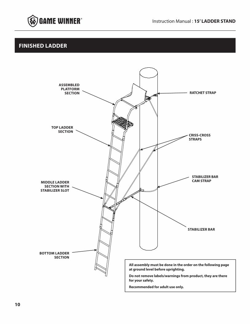
FINISHED LADDER
RATCHET STRAP
CRISS-CROSS STRAPS
STABILIZER BAR CAM STRAP
STABILIZER BAR
MIDDLE LADDER SECTION WITH
STABILIZER SLOT
ASSEMBLED PLATFORM
SECTION
BOTTOM LADDER SECTION
TOP LADDER SECTION
All assembly must be done in the order on the following page at ground level before uprighting.
Do not remove labels/warnings from product, they are there for your safety.
Recommended for adult use only.
Instruction Manual : 15’ LADDER STAND
11
ASSEMBLY INSTRUCTIONS
STEP 1
FIGURE 1
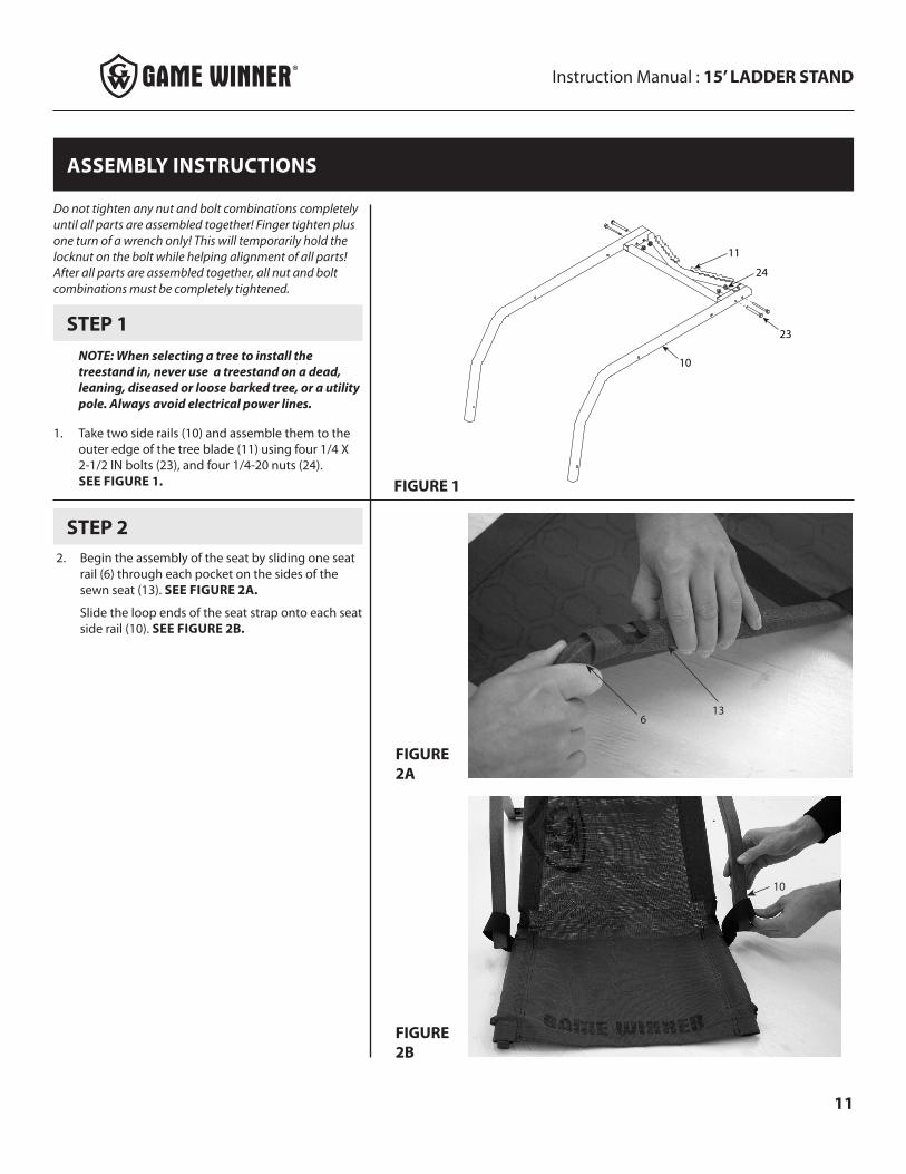
NOTE: When selecting a tree to install the treestand in, never use a treestand on a dead, leaning, diseased or loose barked tree, or a utility pole. Always avoid electrical power lines.
1. Take two side rails (10) and assemble them to the outer edge of the tree blade (11) using four 1/4 X 2-1/2 IN bolts (23), and four 1/4-20 nuts (24). SEE FIGURE 1.
10
23
11
24
FIGURE 2A
FIGURE 2B
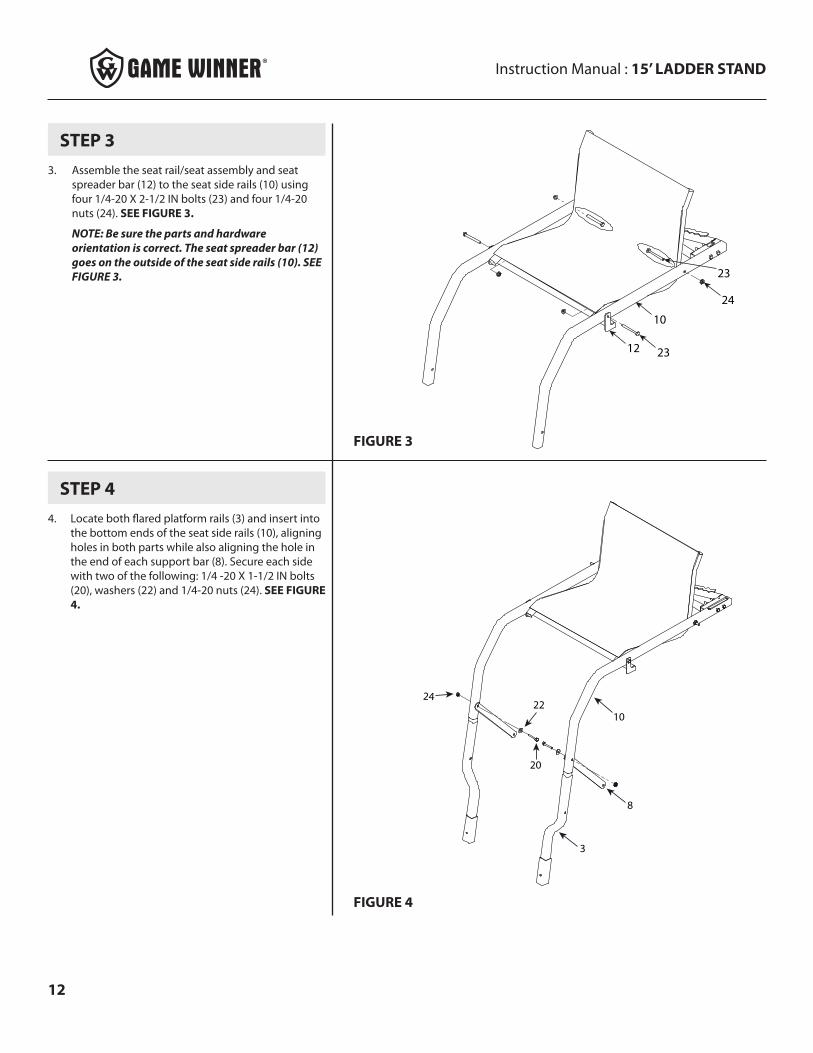
2. Begin the assembly of the seat by sliding one seat rail (6) through each pocket on the sides of the sewn seat (13). SEE FIGURE 2A.
Slide the loop ends of the seat strap onto each seat side rail (10). SEE FIGURE 2B.
136
STEP 2
Do not tighten any nut and bolt combinations completely until all parts are assembled together! Finger tighten plus one turn of a wrench only! This will temporarily hold the locknut on the bolt while helping alignment of all parts! After all parts are assembled together, all nut and bolt combinations must be completely tightened.
10
Instruction Manual : 15’ LADDER STAND
12
STEP 3
10
24
12 23
23
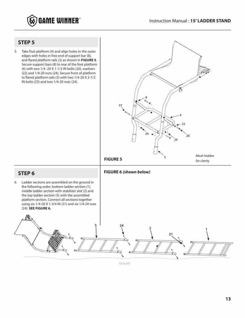
3. Assemble the seat rail/seat assembly and seat spreader bar (12) to the seat side rails (10) using four 1/4-20 X 2-1/2 IN bolts (23) and four 1/4-20 nuts (24). SEE FIGURE 3.
NOTE: Be sure the parts and hardware orientation is correct. The seat spreader bar (12) goes on the outside of the seat side rails (10). SEE FIGURE 3.
FIGURE 3
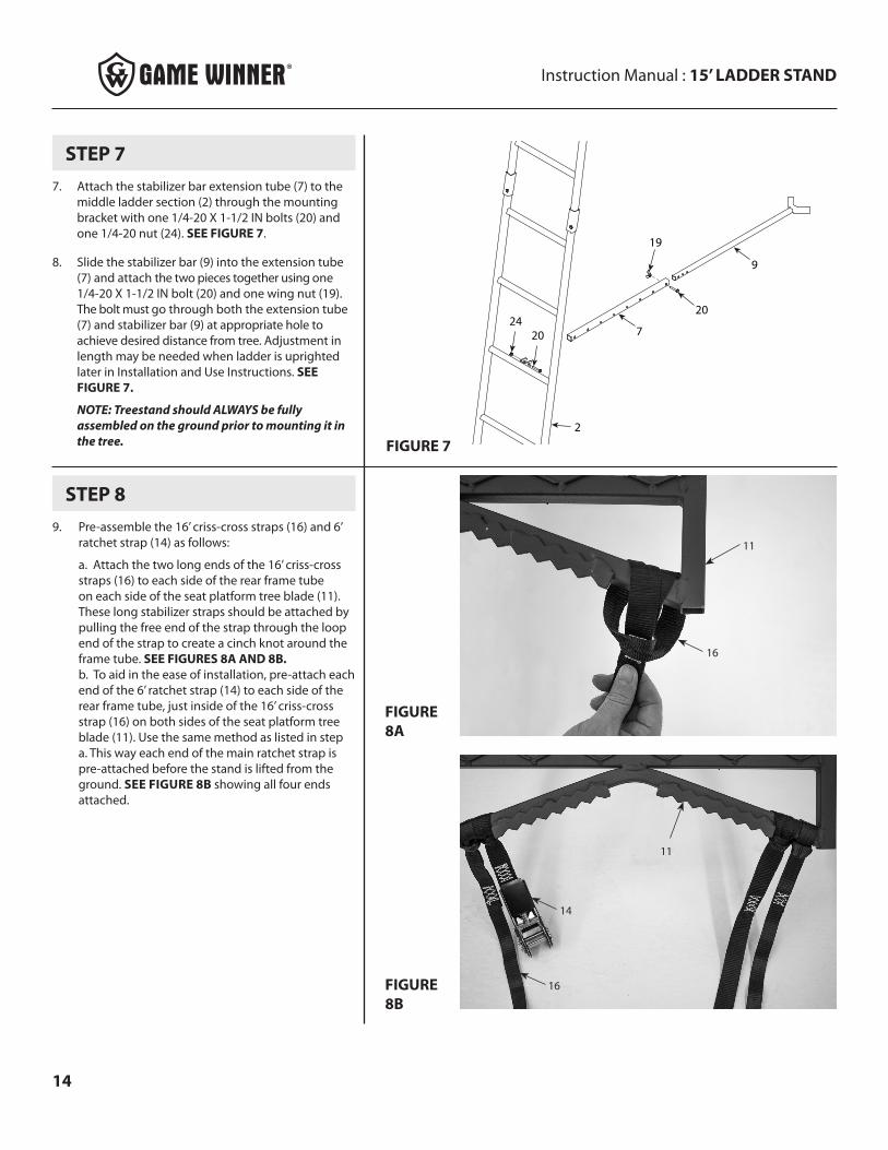
STEP 44. Locate both flared platform rails (3) and insert into
the bottom ends of the seat side rails (10), aligning holes in both parts while also aligning the hole in the end of each support bar (8). Secure each side with two of the following: 1/4 -20 X 1-1/2 IN bolts (20), washers (22) and 1/4-20 nuts (24). SEE FIGURE 4.
10
3
8
20
2224
FIGURE 4
Instruction Manual : 15’ LADDER STAND
13
STEP 55. Take foot platform (4) and align holes in the outer
edges with holes in free end of support bar (8), and flared platform rails (3) as shown in FIGURE 5. Secure support bars (8) to rear of the foot platform (4) with two 1/4 -20 X 1-1/2 IN bolts (20), washers (22) and 1/4-20 nuts (24). Secure front of platform to flared platform rails (3) with two 1/4-20 X 2-1/2 IN bolts (23) and two 1/4-20 nuts (24).
3
4
20
22
24
24
23
8
FIGURE 5Mesh hidden for clarity
STEP 66. Ladder sections are assembled on the ground in
the following order: bottom ladder section (1), middle ladder section with stabilizer slot (2) and the top ladder section (5) with the assembled platform section. Connect all sections together using six 1/4-20 X 1-3/4 IN (21) and six 1/4-20 nuts (24). SEE FIGURE 6.
FIGURE 6 (shown below)
Ground
5 242
211
Instruction Manual : 15’ LADDER STAND
14
FIGURE 8A
FIGURE 8B
STEP 89. Pre-assemble the 16’ criss-cross straps (16) and 6’
ratchet strap (14) as follows:
a. Attach the two long ends of the 16’ criss-cross straps (16) to each side of the rear frame tube on each side of the seat platform tree blade (11). These long stabilizer straps should be attached by pulling the free end of the strap through the loop end of the strap to create a cinch knot around the frame tube. SEE FIGURES 8A AND 8B. b. To aid in the ease of installation, pre-attach each end of the 6’ ratchet strap (14) to each side of the rear frame tube, just inside of the 16’ criss-cross strap (16) on both sides of the seat platform tree blade (11). Use the same method as listed in step a. This way each end of the main ratchet strap is pre-attached before the stand is lifted from the ground. SEE FIGURE 8B showing all four ends attached.
11
16
14
16
11
STEP 77. Attach the stabilizer bar extension tube (7) to the
middle ladder section (2) through the mounting bracket with one 1/4-20 X 1-1/2 IN bolts (20) and one 1/4-20 nut (24). SEE FIGURE 7.
8. Slide the stabilizer bar (9) into the extension tube (7) and attach the two pieces together using one 1/4-20 X 1-1/2 IN bolt (20) and one wing nut (19). The bolt must go through both the extension tube (7) and stabilizer bar (9) at appropriate hole to achieve desired distance from tree. Adjustment in length may be needed when ladder is uprighted later in Installation and Use Instructions. SEE FIGURE 7.
NOTE: Treestand should ALWAYS be fully assembled on the ground prior to mounting it in the tree. FIGURE 7
7
9
20
19
2024
2
Instruction Manual : 15’ LADDER STAND
15
WARNING
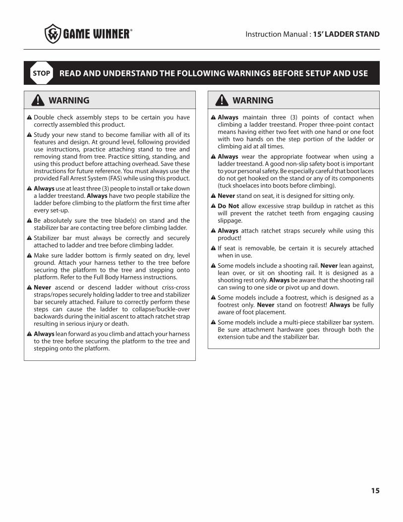
Double check assembly steps to be certain you have correctly assembled this product.
Study your new stand to become familiar with all of its features and design. At ground level, following provided use instructions, practice attaching stand to tree and removing stand from tree. Practice sitting, standing, and using this product before attaching overhead. Save these instructions for future reference. You must always use the provided Fall Arrest System (FAS) while using this product.
Always use at least three (3) people to install or take down a ladder treestand. Always have two people stabilize the ladder before climbing to the platform the first time after every set-up.
Be absolutely sure the tree blade(s) on stand and the stabilizer bar are contacting tree before climbing ladder.
Stabilizer bar must always be correctly and securely attached to ladder and tree before climbing ladder.
Make sure ladder bottom is firmly seated on dry, level ground. Attach your harness tether to the tree before securing the platform to the tree and stepping onto platform. Refer to the Full Body Harness instructions.
Never ascend or descend ladder without criss-cross straps/ropes securely holding ladder to tree and stabilizer bar securely attached. Failure to correctly perform these steps can cause the ladder to collapse/buckle-over backwards during the initial ascent to attach ratchet strap resulting in serious injury or death.
Always lean forward as you climb and attach your harness to the tree before securing the platform to the tree and stepping onto the platform.
WARNING
Always maintain three (3) points of contact when climbing a ladder treestand. Proper three-point contact means having either two feet with one hand or one foot with two hands on the step portion of the ladder or climbing aid at all times.
Always wear the appropriate footwear when using a ladder treestand. A good non-slip safety boot is important to your personal safety. Be especially careful that boot laces do not get hooked on the stand or any of its components (tuck shoelaces into boots before climbing).
Never stand on seat, it is designed for sitting only.
Do Not allow excessive strap buildup in ratchet as this will prevent the ratchet teeth from engaging causing slippage.
Always attach ratchet straps securely while using this product!
If seat is removable, be certain it is securely attached when in use.
Some models include a shooting rail. Never lean against, lean over, or sit on shooting rail. It is designed as a shooting rest only. Always be aware that the shooting rail can swing to one side or pivot up and down.
Some models include a footrest, which is designed as a footrest only. Never stand on footrest! Always be fully aware of foot placement.
Some models include a multi-piece stabilizer bar system. Be sure attachment hardware goes through both the extension tube and the stabilizer bar.
READ AND UNDERSTAND THE FOLLOWING WARNINGS BEFORE SETUP AND USESTOP

Instruction Manual : 15’ LADDER STAND
16
INSTALLATION AND USE INSTRUCTIONS
1. With assembled product lying on the ground, position one person at bottom end of ladder lying on the ground. This person has to prevent the ladder end from tilting up when platform end is lifted and prevent the ladder from skidding across ground.
2. a. Position two people at the platform end of the ladder, lift the platform end and continue uprighting by walking toward bottom end of ladder and moving hands along ladder legs. Stand ladder up against chosen straight tree on dry, level ground. Use caution when ladder comes over center against the tree. SEE FIGURE 9A.
b. Step back and look at the ladder top to see that it is level. Adjust as needed to achieve a level platform top. Make sure tree blade is contacting tree. SEE FIGURE 9B.
c. Step down hard on bottom step to push ladder legs into the ground. SEE FIGURE 9C.
STEP 1
FIGURE 9
WARNING
Never use a treestand on a dead, leaning, diseased or loose barked tree, or a utility pole. Always avoid electrical power lines.
Bring ratchet strap(s) up with you in a pocket - Do Not carry in your hands!
During installation and removal of ladder treestands, you must always and properly use the included Full Body Harness (Fall Arrest System). Refer to the Full Body Harness instructions included with this product for proper use.
A
A
CB
3. While two people holding the stand in place, the third person should connect the horizontal stabilizer bar to the tree. Adjust the length of the stabilizer bar as needed so it contacts the tree and is level to the ground. Then secure it to the tree with the 6’ cam strap (17) by forming a cinch knot with both ends of the strap and running the long end of the strap through the cam buckle. SEE FIGURES 10A AND 10B.
FIGURE 10A
FIGURE 10B
STEP 2
Instruction Manual : 15’ LADDER STAND
17
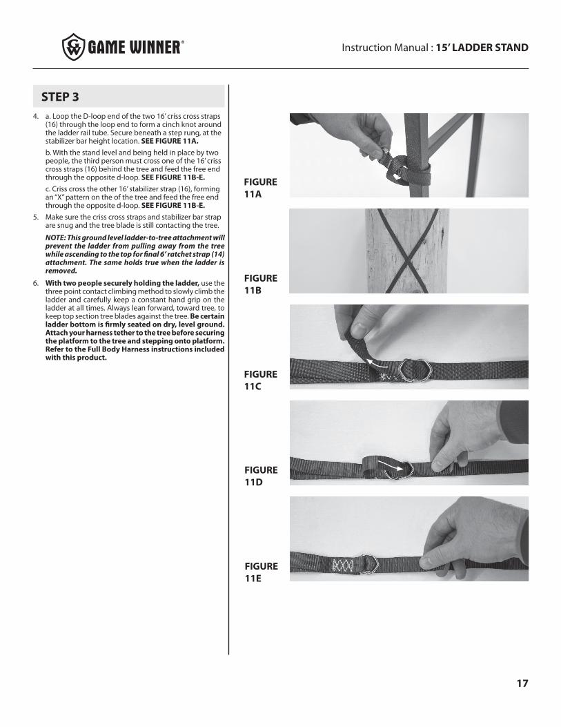
4. a. Loop the D-loop end of the two 16’ criss cross straps (16) through the loop end to form a cinch knot around the ladder rail tube. Secure beneath a step rung, at the stabilizer bar height location. SEE FIGURE 11A.b. With the stand level and being held in place by two people, the third person must cross one of the 16’ criss cross straps (16) behind the tree and feed the free end through the opposite d-loop. SEE FIGURE 11B-E.c. Criss cross the other 16’ stabilizer strap (16), forming an “X” pattern on the of the tree and feed the free end through the opposite d-loop. SEE FIGURE 11B-E.
5. Make sure the criss cross straps and stabilizer bar strap are snug and the tree blade is still contacting the tree.
NOTE: This ground level ladder-to-tree attachment will prevent the ladder from pulling away from the tree while ascending to the top for final 6’ ratchet strap (14) attachment. The same holds true when the ladder is removed.
6. With two people securely holding the ladder, use the three point contact climbing method to slowly climb the ladder and carefully keep a constant hand grip on the ladder at all times. Always lean forward, toward tree, to keep top section tree blades against the tree. Be certain ladder bottom is firmly seated on dry, level ground. Attach your harness tether to the tree before securing the platform to the tree and stepping onto platform. Refer to the Full Body Harness instructions included with this product.
STEP 3
FIGURE 11A
FIGURE 11B
FIGURE 11C
FIGURE 11D
FIGURE 11E
Instruction Manual : 15’ LADDER STAND
18
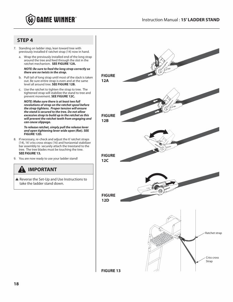
7. Standing on ladder step, lean toward tree with previously installed 6’ ratchet strap (14) now in hand.
a. Wrap the previously installed end of the long strap around the tree and feed through the slot in the ratchet mechanism. SEE FIGURE 12A.
NOTE: Be sure to feed the long strap correctly so there are no twists in the strap.
b. Pull tail of long strap until most of the slack is taken out. Be sure entire strap is even and at the same level all around tree. SEE FIGURE 12B.
c. Use the ratchet to tighten the strap to tree. The tightened strap will stabilize the stand to tree and prevent movement. SEE FIGURE 12C.
NOTE: Make sure there is at least two full revolutions of strap on the ratchet spool before the strap tightens. Proper tension will ensure the stand is secured to the tree. Do not allow excessive strap to build up in the ratchet as this will prevent the ratchet teeth from engaging and can cause slippage.
To release ratchet, simply pull the release lever and open tightening lever wide open (flat). SEE FIGURE 12D.
8. If necessary, re-check and adjust the 6’ ratchet straps (14), 16’ criss cross straps (16) and horizontal stabilizer bar assembly to securely attach the treestand to the tree. The tree blades must be touching the tree. SEE FIGURE 13.
9. You are now ready to use your ladder stand!
STEP 4
IMPORTANT
Reverse the Set-Up and Use Instructions to take the ladder stand down.
FIGURE 12A
FIGURE 12B
FIGURE 12C
FIGURE 12D
FIGURE 13
Criss cross Strap
Ratchet strap

Instruction Manual : 15’ LADDER STAND
19
NOTES
BEFORE EACH USE PERFORM THE FOLLOWING:
• Inspect all webbing, rope, cord, and strap assemblies for wear or damage.
• Inspect cables and/or cable ends for damage or kinking.
• Inspect all hardware and chain components for damage or wear.
• Inspect for any structural damage to product. (If any exists stop use immediately and call RETI Customer Service.)
• Inspect all nut and bolt assemblies to be certain none are loose.
• Inspect for any missing parts.
• Lubricate all pivot and slide together points with powder graphite, petroleum jelly or silicone spray to prevent noise, wear and rust.
• Inspect entire product for any rust, corrosion, cracks, freezing, excessive heat or rotting damage that may effect the safety of your product. Discard any questionable product.
• Inspect entire product for any structural damage - pay close attention to all weld locations. (Discard product if any damage is found.)
• Using correct wrenches inspect all nut & bolt assembly locations and snug up any that may be loose. Be careful not to crush tubing when tightening!
• Inspect and check operation of all cables, cable ends, cord, rope, webbing, and strap or chain assemblies. Replace with RETI original replacement parts any item or assembly that shows signs of wear, damage, kinking, or functions incorrectly.
• Inspect seat for damage or wear. Replace any seat with factory new that shows signs of structural damage or wear.
• Never modify your stand in any way by making repairs, replacing parts, or altering by adding or attaching anything to it except if explicitly authorized in writing by the manufacturer.
INSPECTION AND MAINTENANCE

*All weights, specifications and features are approximate and are subject to change without notice. Due to continuous product improvements, product images may not be exact. Warning labels in some product images may have been removed for photography purposes only. Props shown in photos not included. Some assembly may be required.