Sturdevant ’ s - Root Canal Foundation · Chapter 19 Introduction to Amalgam Restorations 339...
44
Transcript of Sturdevant ’ s - Root Canal Foundation · Chapter 19 Introduction to Amalgam Restorations 339...
Sturdevant ’ s Art and Science of
OPERATIVE DENTISTRY A South Asian Edition
US Editors
Harald O Heymann, DDS, MEd Professor , Department of Operative Dentistry
The University of North Carolina , School of Dentistry Chapel Hill, NC
Edward J Swift, Jr, DMD, MS Professor and Chair , Department of Operative Dentistry The University of North Carolina , School of Dentistry
Chapel Hill, NC
Andr é V Ritter, DDS, MS Professor and Graduate Program Director , Department of Operative Dentistry
The University of North Carolina , School of Dentistry Chapel Hill, NC
Adaptation Editor
V Gopikrishna, MDS, FISDRProfessor
Department of Conservative Dentistry and EndodonticsThai Moogambigai Dental College
Dr MGR Educational and Research Institute UniversityChennai, INDIA
ELSEVIERA division of
Reed Elsevier India Private Limited
Prelims.indd iiiPrelims.indd iii 24/06/13 4:40 PM24/06/13 4:40 PM
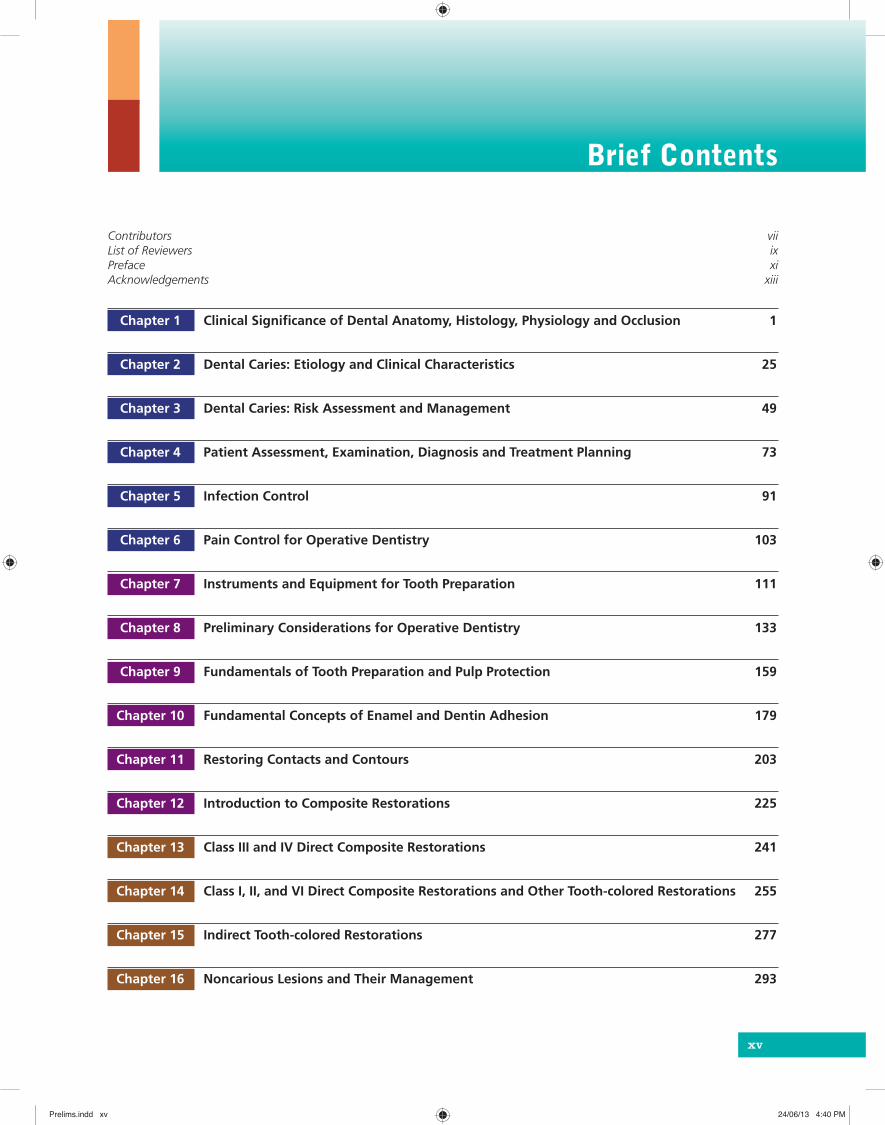
Brief Contents
Contributors viiList of Reviewers ixPreface xiAcknowledgements xiii
Chapter 1 Clinical Signifi cance of Dental Anatomy, Histology, Physiology and Occlusion 1
Chapter 2 Dental Caries: Etiology and Clinical Characteristics 25
Chapter 3 Dental Caries: Risk Assessment and Management 49
Chapter 4 Patient Assessment, Examination, Diagnosis and Treatment Planning 73
Chapter 5 Infection Control 91
Chapter 6 Pain Control for Operative Dentistry 103
Chapter 7 Instruments and Equipment for Tooth Preparation 111
Chapter 8 Preliminary Considerations for Operative Dentistry 133
Chapter 9 Fundamentals of Tooth Preparation and Pulp Protection 159
Chapter 10 Fundamental Concepts of Enamel and Dentin Adhesion 179
Chapter 11 Restoring Contacts and Contours 203
Chapter 12 Introduction to Composite Restorations 225
Chapter 13 Class III and IV Direct Composite Restorations 241
Chapter 14 Class I, II, and VI Direct Composite Restorations and Other Tooth-colored Restorations 255
Chapter 15 Indirect Tooth-colored Restorations 277
Chapter 16 Noncarious Lesions and Their Management 293
xv
Prelims.indd xvPrelims.indd xv 24/06/13 4:40 PM24/06/13 4:40 PM
xvi Brief Contents
Chapter 17 Additional Conservative Esthetic Procedures 303
Chapter 18 Dentin Hypersensitivity 333
Chapter 19 Introduction to Amalgam Restorations 339
Chapter 20 Class I and II Amalgam Restorations 361
Chapter 21 Complex Amalgam Restorations 389
Chapter 22 Dental Cements 403
Chapter 23 Direct Gold Restorations 419
Chapter 24 Class II Cast Metal Restorations 429
Index 469
Prelims.indd xviPrelims.indd xvi 24/06/13 4:40 PM24/06/13 4:40 PM
C H A P T E R
1
1
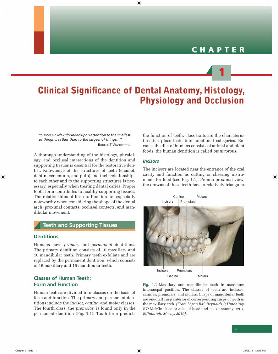
the function of teeth; class traits are the characteris-tics that place teeth into functional categories. Be-cause the diet of humans consists of animal and plant foods, the human dentition is called omnivorous.
Incisors
The incisors are located near the entrance of the oral cavity and function as cutting or shearing instru-ments for food (see Fig. 1.1). From a proximal view, the crowns of these teeth have a relatively triangular
Clinical Signifi cance of Dental Anatomy, Histology, Physiology and Occlusion
“Success in life is founded upon attention to the smallest of things… rather than to the largest of things…”
—BOOKER T WASHINGTON
A thorough understanding of the histology, physiol-ogy, and occlusal interactions of the dentition and supporting tissues is essential for the restorative den-tist. Knowledge of the structures of teeth (enamel, dentin, cementum, and pulp) and their relationships to each other and to the supporting structures is nec-essary, especially when treating dental caries. Proper tooth form contributes to healthy supporting tissues. The relationships of form to function are especially noteworthy when considering the shape of the dental arch, proximal contacts, occlusal contacts, and man-dibular movement.
Teeth and Supporting Tissues
Dentitions
Humans have primary and permanent dentitions. The primary dentition consists of 10 maxillary and 10 mandibular teeth. Primary teeth exfoliate and are replaced by the permanent dentition, which consists of 16 maxillary and 16 mandibular teeth.
Classes of Human Teeth: Form and Function
Human teeth are divided into classes on the basis of form and function. The primary and permanent den-titions include the incisor, canine, and molar classes. The fourth class, the premolar, is found only in the permanent dentition (Fig. 1.1). Tooth form predicts
Fig. 1.1 Maxillary and mandibular teeth in maximum intercuspal position. The classes of teeth are incisors, canines, premolars, and molars. Cusps of mandibular teeth are one-half cusp anterior of corresponding cusps of teeth in the maxillary arch. (From Logan BM, Reynolds P, Hutchings RT: McMinn’s color atlas of head and neck anatomy, ed 4, Edinburgh, Mosby, 2010).
Incisors
Incisors
Canine
Canine
Premolars
Premolars
Molars
Molars
Chapter 01.indd 1Chapter 01.indd 1 25/06/13 12:51 PM25/06/13 12:51 PM
2 Sturdevant’s Art and Science of Operative Dentistry
shape, with a narrow incisal surface and a broad cer-vical base. During mastication, incisors are used to shear (cut through) food.
Cl in i ca l Notes
Incisors are essential for the proper esthetics of the smile, facial soft tissue contours (e.g. lip support), and speech (phonetics).
Canines
Canines possess the longest roots of all teeth and are located at the corners of the dental arch. They func-tion in the seizing, piercing, tearing, and cutting of food. From a proximal view, the crown also has a tri-angular shape, with a thick incisal ridge. The anatom-ic form of the crown and the length of the root make these teeth strong, stable abutment teeth for a fi xed or removable prosthesis.
Cl in i ca l Notes
Canines not only serve as important guides in occlu-sion because of their anchorage and position in the dental arches but also play a crucial role (along with the incisors) in the esthetics of smile and lip support (see Fig. 1.1).
Premolars
Premolars serve a dual role:
(1) They are similar to canines in the tearing of food.
(2) They are similar to molars in the grinding of food.
The occlusal surfaces of the premolars present a series of curves in the form of concavities and con-vexities that should be maintained throughout life for correct occlusal contacts and function.
Cl in i ca l Notes
Although less visible than incisors and canines, pre-molars still can play an important role in esthetics.
Molars
Molars are large, multicusped, strongly anchored teeth located nearest to the temporomandibular joint
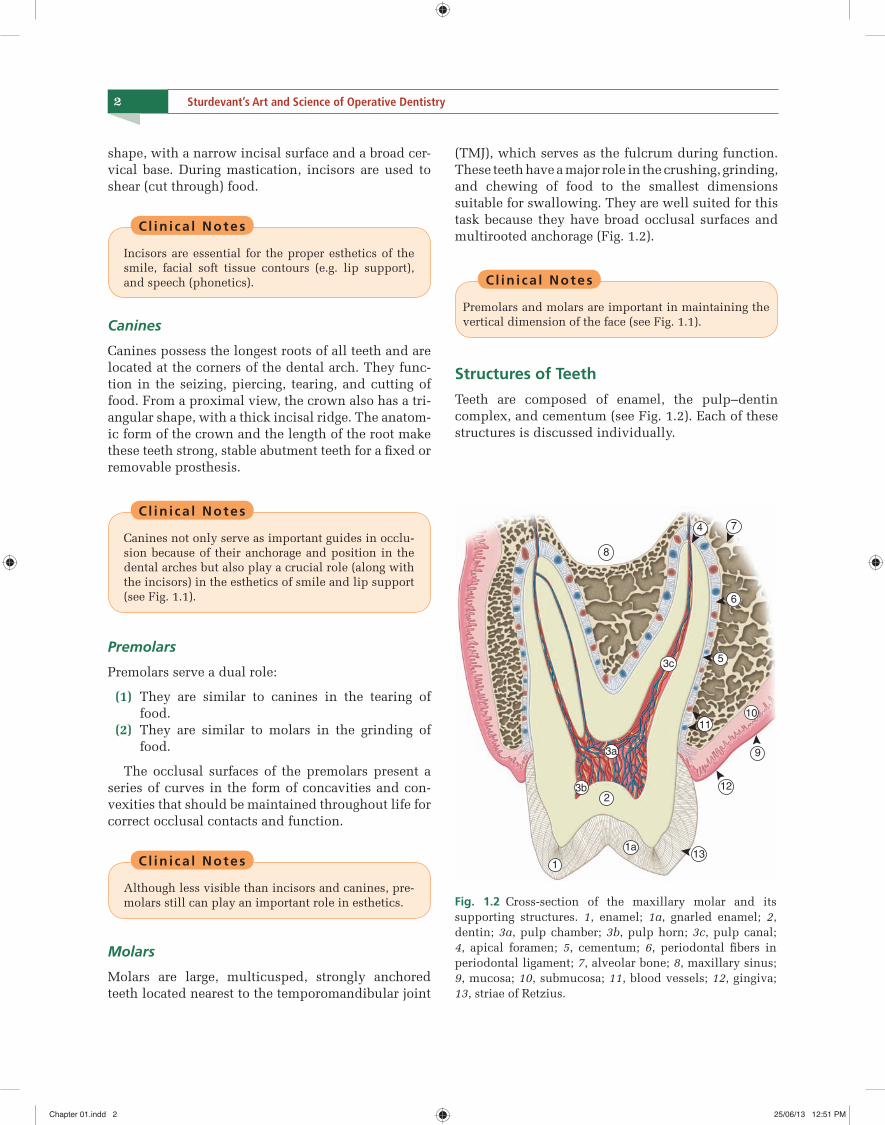
(TMJ), which serves as the fulcrum during function. These teeth have a major role in the crushing, grinding, and chewing of food to the smallest dimensions suitable for swallowing. They are well suited for this task because they have broad occlusal surfaces and multirooted anchorage (Fig. 1.2).
Cl in i ca l Notes
Premolars and molars are important in maintaining the vertical dimension of the face (see Fig. 1.1).
Structures of Teeth
Teeth are composed of enamel, the pulp–dentin complex, and cementum (see Fig. 1.2). Each of these structures is discussed individually.
3c
1110
9
12
5
6
8
4 7
3a
131a
23b
1
Fig. 1.2 Cross-section of the maxillary molar and its supporting structures. 1, enamel; 1a, gnarled enamel; 2, dentin; 3a, pulp chamber; 3b, pulp horn; 3c, pulp canal; 4, apical foramen; 5, cementum; 6, perio dontal fi bers in periodontal ligament; 7, alveolar bone; 8, maxillary sinus; 9, mucosa; 10, submucosa; 11, blood vessels; 12, gingiva; 13, striae of Retzius.
Chapter 01.indd 2Chapter 01.indd 2 25/06/13 12:51 PM25/06/13 12:51 PM
C H A P T E R
2
25
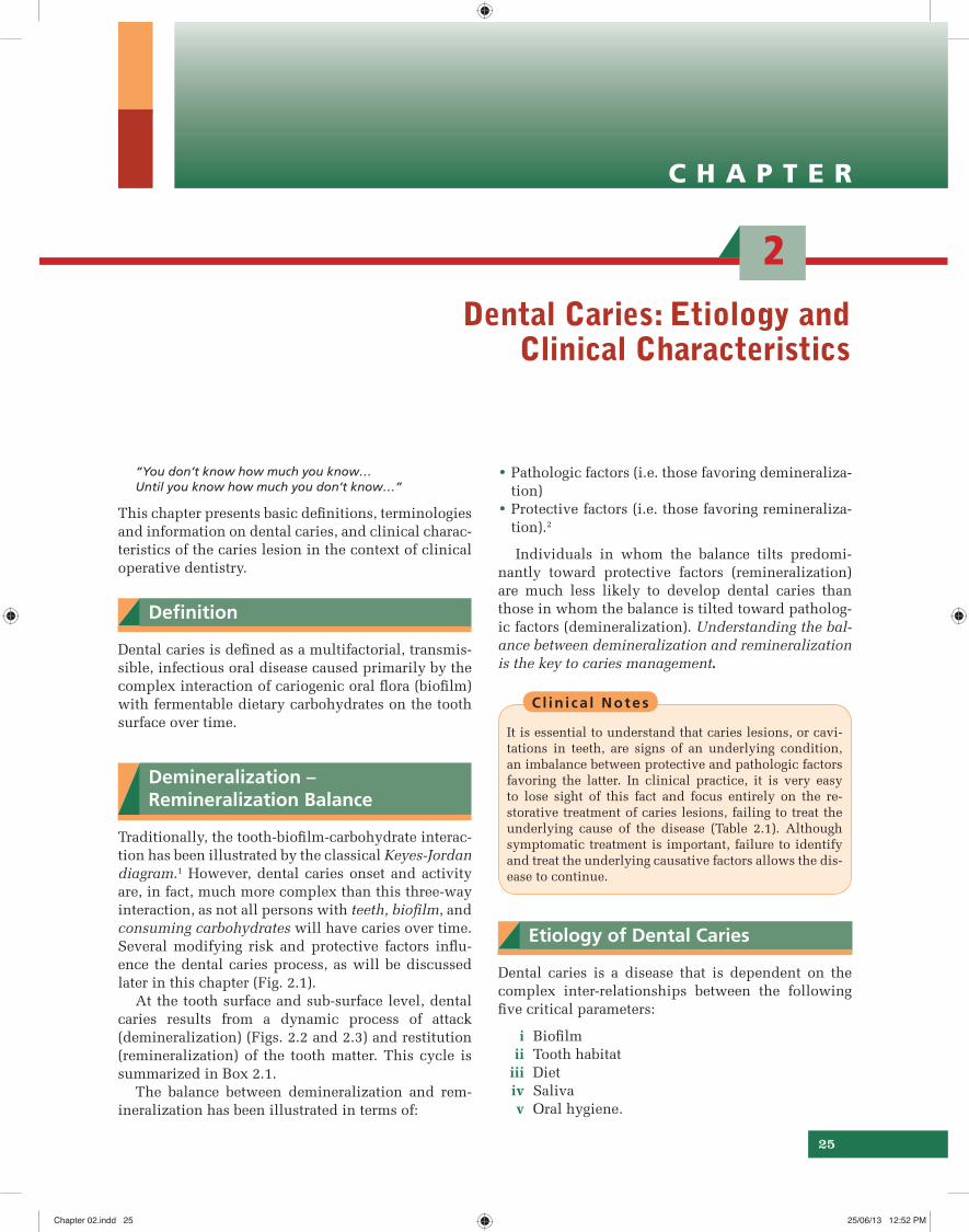
• Pathologic factors (i.e. those favoring demineraliza-tion) • Protective factors (i.e. those favoring remineraliza-tion).2
Individuals in whom the balance tilts predomi-nantly toward protective factors (remineralization) are much less likely to develop dental caries than those in whom the balance is tilted toward patholog-ic factors (demineralization). Understanding the bal-ance between demineralization and remineralization is the key to caries management.
Cl in i ca l Notes
It is essential to understand that caries lesions, or cavi-tations in teeth, are signs of an underlying condition, an imbalance between protective and pathologic factors favoring the latter. In clinical practice, it is very easy to lose sight of this fact and focus entirely on the re-storative treatment of caries lesions, failing to treat the underlying cause of the disease (Table 2.1). Although symptomatic treatment is important, failure to identify and treat the underlying causative factors allows the dis-ease to continue.
Etiology of Dental Caries
Dental caries is a disease that is dependent on the complex inter-relationships between the following fi ve critical parameters:
i Biofi lm ii Tooth habitat iii Diet iv Saliva v Oral hygiene.
Dental Caries: Etiology and Clinical Characteristics
“You don’t know how much you know… Until you know how much you don’t know…”
This chapter presents basic defi nitions, terminologies and information on dental caries, and clinical charac-teristics of the caries lesion in the context of clinical operative dentistry.
Defi nition
Dental caries is defi ned as a multifactorial, transmis-sible, infectious oral disease caused primarily by the complex interaction of cariogenic oral fl ora (biofi lm) with fermentable dietary carbohydrates on the tooth surface over time.
Demineralization – Remineralization Balance
Traditionally, the tooth-biofi lm-carbohydrate interac-tion has been illustrated by the classical Keyes-Jordan diagram.1 However, dental caries onset and activity are, in fact, much more complex than this three-way interaction, as not all persons with teeth, biofi lm, and consuming carbohydrates will have caries over time. Several modifying risk and protective factors infl u-ence the dental caries process, as will be discussed later in this chapter (Fig. 2.1).
At the tooth surface and sub-surface level, dental caries results from a dynamic process of attack (demineralization) (Figs. 2.2 and 2.3) and restitution (remineralization) of the tooth matter. This cycle is summarized in Box 2.1.
The balance between demineralization and rem-ineralization has been illustrated in terms of:
Chapter 02.indd 25Chapter 02.indd 25 25/06/13 12:52 PM25/06/13 12:52 PM
42 Sturdevant’s Art and Science of Operative Dentistry
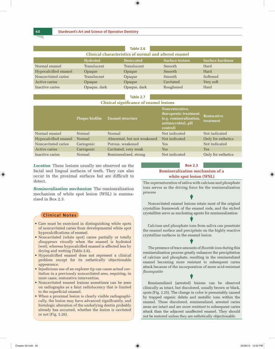
Table 2.6
Clinical characteristics of normal and altered enamelHydrated Desiccated Surface texture Surface hardness
Normal enamel Translucent Translucent Smooth HardHypocalcifi ed enamel Opaque Opaque Smooth HardNoncavitated caries Translucent Opaque Smooth SoftenedActive caries Opaque Opaque Cavitated Very softInactive caries Opaque, dark Opaque, dark Roughened Hard
Table 2.7
Clinical signifi cance of enamel lesions
Plaque biofi lm Enamel structure
Nonrestorative, therapeutic treatment (e.g. remineralization, antimicrobial, pH control)
Restorative treatment
Normal enamel Normal Normal Not indicated Not indicatedHypocalcifi ed enamel Normal Abnormal, but not weakened Not indicated Only for estheticsNoncavitated caries Cariogenic Porous, weakened Yes Not indicatedActive caries Cariogenic Cavitated, very weak Yes YesInactive caries Normal Remineralized, strong Not indicated Only for esthetics
Box 2.3
Remineralization mechanism of a white spot lesion (WSL)
The supersaturation of saliva with calcium and phosphate ions serves as the driving force for the remineralization process
Noncavitated enamel lesions retain most of the original crystalline framework of the enamel rods, and the etched crystallites serve as nucleating agents for remineralization
Calcium and phosphate ions from saliva can penetrate the enamel surface and precipitate on the highly reactive crystalline surfaces in the enamel lesion
The presence of trace amounts of fl uoride ions during this remineralization process greatly enhances the precipitation of calcium and phosphate, resulting in the remineralized enamel becoming more resistant to subsequent caries attack because of the incorporation of more acid-resistant fl uorapatite
Remineralized (arrested) lesions can be observed clinically as intact, but discolored, usually brown or black, spots (Fig. 2.25). The change in color is presumably caused by trapped organic debris and metallic ions within the enamel. These discolored, remineralized, arrested caries areas are intact and are more resistant to subsequent caries attack than the adjacent unaffected enamel. They should not be restored unless they are esthetically objectionable
Location These lesions usually are observed on the facial and lingual surfaces of teeth. They can also occur in the proximal surfaces but are diffi cult to detect.
Remineralization mechanism The remineralization mechanism of white spot lesion (WSL) is summa-rized in Box 2.3.
Cl in i ca l Notes
• Care must be exercised in distinguishing white spots of noncavitated caries from developmental white spot hypocalcifi cations of enamel.
• Noncavitated (white spot) caries partially or totally disappears visually when the enamel is hydrated (wet), whereas hypocalcifi ed enamel is affected less by drying and wetting (Table 2.6).
• Hypocalcifi ed enamel does not represent a clinical problem except for its esthetically objectionable appearance.
• Injudicious use of an explorer tip can cause actual cav-itation in a previously noncavitated area, requiring, in most cases, restorative intervention.
• Noncavitated enamel lesions sometimes can be seen on radiographs as a faint radiolucency that is limited to the superfi cial enamel.
• When a proximal lesion is clearly visible radiographi-cally, the lesion may have advanced signifi cantly, and histologic alteration of the underlying dentin probably already has occurred, whether the lesion is cavitated or not (Fig. 2.26).
Chapter 02.indd 42Chapter 02.indd 42 25/06/13 12:52 PM25/06/13 12:52 PM
45CHAPTER 2 Dental Caries: Etiology and Clinical Characteristics
Hypermineralized areas may be seen on radio-graphs as zones of increased radiopacity (often S-shaped following the course of the tubules) ahead of the advancing, infected portion of the lesion. This re-pair occurs only if the tooth pulp is vital.
Sclerotic dentin Dentin that has more mineral con-tent than normal dentin is termed sclerotic dentin.
Sclerotic dentin formation occurs ahead of the demineralization front of a slowly advancing lesion and may be seen under an old restoration.
Sclerotic dentin is usually shiny and darker in color but feels hard to the explorer tip. By contrast, normal, freshly cut dentin lacks a shiny, refl ective surface and allows some penetration from a sharp ex-plorer tip.
The apparent function of sclerotic dentin is to wall off a lesion by blocking (sealing) the tubules.
The permeability of sclerotic dentin is greatly re-duced compared with normal dentin because of the decrease in the tubule lumen diameter.24
2. Reaction to a moderate-intensity attack The second level of dentinal response is to moderate-intensity irritants by forming reparative dentin.
Mechanism of reparative dentin formationThe mechanism of reparative dentin formation is ex-plained in Flowchart 2.1.
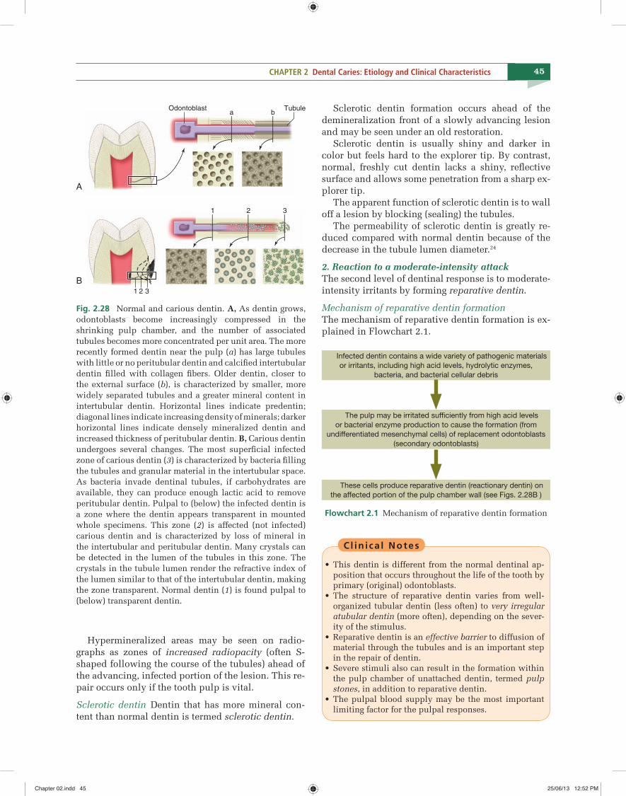
A
B
Odontoblast Tubulea
1 2 3
b
1 2 3
Fig. 2.28 Normal and carious dentin. A, As dentin grows, odontoblasts become increasingly compressed in the shrinking pulp chamber, and the number of associated tubules becomes more concentrated per unit area. The more recently formed dentin near the pulp (a) has large tubules with little or no peritubular dentin and calcifi ed intertubular dentin fi lled with collagen fi bers. Older dentin, closer to the external surface (b), is characterized by smaller, more widely separated tubules and a greater mineral content in intertubular dentin. Horizontal lines indicate predentin; diagonal lines indicate increasing density of minerals; darker horizontal lines indicate densely mineralized dentin and increased thickness of peritubular dentin. B, Carious dentin undergoes several changes. The most superfi cial infected zone of carious dentin (3) is characterized by bacteria fi lling the tubules and granular material in the intertubular space. As bacteria invade dentinal tubules, if carbohydrates are available, they can produce enough lactic acid to remove peritubular dentin. Pulpal to (below) the infected dentin is a zone where the dentin appears transparent in mounted whole specimens. This zone (2) is affected (not infected) carious dentin and is characterized by loss of mineral in the intertubular and peritubular dentin. Many crystals can be detected in the lumen of the tubules in this zone. The crystals in the tubule lumen render the refractive index of the lumen similar to that of the intertubular dentin, making the zone transparent. Normal dentin (1) is found pulpal to (below) transparent dentin.
Infected dentin contains a wide variety of pathogenic materials
or irritants, including high acid levels, hydrolytic enzymes,
bacteria, and bacterial cellular debris
The pulp may be irritated suffi ciently from high acid levels
or bacterial enzyme production to cause the formation (from
undifferentiated mesenchymal cells) of replacement odontoblasts
(secondary odontoblasts)
These cells produce reparative dentin (reactionary dentin) on
the affected portion of the pulp chamber wall (see Figs. 2.28B )
Flowchart 2.1 Mechanism of reparative dentin formation
Cl in i ca l Notes
• This dentin is different from the normal dentinal ap-position that occurs throughout the life of the tooth by primary (original) odontoblasts.
• The structure of reparative dentin varies from well-organized tubular dentin (less often) to very irregular atubular dentin (more often), depending on the sever-ity of the stimulus.
• Reparative dentin is an effective barrier to diffusion of material through the tubules and is an important step in the repair of dentin.
• Severe stimuli also can result in the formation within the pulp chamber of unattached dentin, termed pulp stones, in addition to reparative dentin.
• The pulpal blood supply may be the most important limiting factor for the pulpal responses.
Chapter 02.indd 45Chapter 02.indd 45 25/06/13 12:52 PM25/06/13 12:52 PM
C H A P T E R
3
49
Dental Caries:Risk Assessment and Management
“There are no such things as incurables…There are only things for which man has not yet found a cure…”
—BERNARD BARUCH
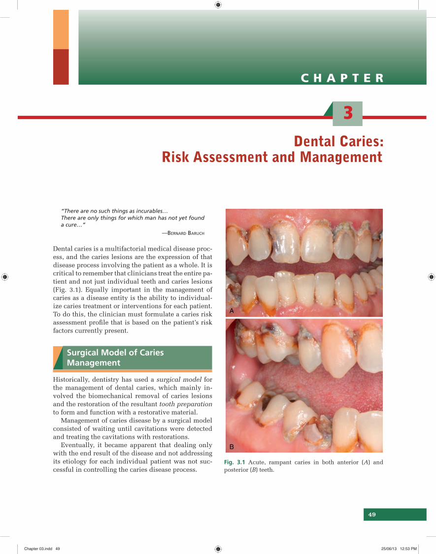
Dental caries is a multifactorial medical disease proc-ess, and the caries lesions are the expression of that disease process involving the patient as a whole. It is critical to remember that clinicians treat the entire pa-tient and not just individual teeth and caries lesions (Fig. 3.1). Equally important in the management of caries as a disease entity is the ability to individual-ize caries treatment or interventions for each patient. To do this, the clinician must formulate a caries risk assessment profi le that is based on the patient’s risk factors currently present.
Surgical Model of Caries Management
Historically, dentistry has used a surgical model for the management of dental caries, which mainly in-volved the biomechanical removal of caries lesions and the restoration of the resultant tooth preparation to form and function with a restorative material.
Management of caries disease by a surgical model consisted of waiting until cavitations were detected and treating the cavitations with restorations.
Eventually, it became apparent that dealing only with the end result of the disease and not addressing its etiology for each individual patient was not suc-cessful in controlling the caries disease process.
Fig. 3.1 Acute, rampant caries in both anterior (A) and posterior (B) teeth.
Chapter 03.indd 49Chapter 03.indd 49 25/06/13 12:53 PM25/06/13 12:53 PM
60 Sturdevant’s Art and Science of Operative Dentistry
weeks. Chlorhexidine may be used in combination with other preventive measures in high-risk patients.
Cl in i ca l Notes
The traditional approach is the use of chlorhexidine (CHX) mouthwash, varnish, or both, along with pre-scription fl uoride toothpaste. When using this approach, it may be prudent to use toothpaste free from sodium lauryl sulfate (SLS), which causes the foaming action in dentifrices. Although data are equivocal, evidence dem-onstrates that SLS reduces the ability of CHX to reduce plaque formation.31
2. Xylitol Xylitol is a natural fi ve-carbon sugar obtained from birch trees. It seems to have several mechanisms of action to reduce the incidence of caries. • Xylitol keeps the sucrose molecule from binding with MS. • S. mutans cannot ferment (metabolize) xylitol, so no acid is produced. • Xylitol reduces MS by altering the metabolic path-ways. • Finally there is some suggestion that xylitol may enhance remineralization and help arrest dentinal caries.32 ,33
Cl in i ca l Notes
• It is usually recommended that a patient chew a piece of xylitol gum for 5–30 minutes after eating or snack-ing.
• Chewing any sugar-free gum after meals reduces the acidogenicity of plaque because chewing stimulates salivary fl ow, which improves the buffering of the pH drop that occurs after eating.34
• Reductions in caries rates are greater, however, when xylitol is used as the sugar substitute.35,36
• Its effi cacy is dose related, so care must be taken to rec-ommend products with adequate dose levels. Current protocols suggest chewing two pieces of gum contain-ing a total of 1 gram of xylitol three to six times per day, preferably after meals and snacks.
VIII. Calcium and Phosphate Compounds
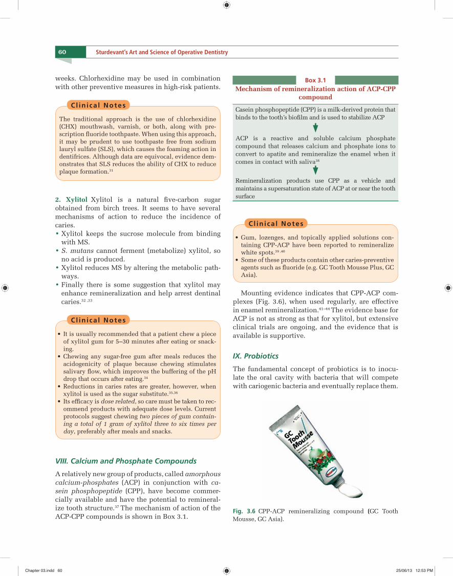
A relatively new group of products, called amorphous calcium-phosphates (ACP) in conjunction with ca-sein phosphopeptide (CPP), have become commer-cially available and have the potential to remineral-ize tooth structure.37 The mechanism of action of the ACP-CPP compounds is shown in Box 3.1.
Cl in i ca l Notes
• Gum, lozenges, and topically applied solutions con-taining CPP-ACP have been reported to remineralize white spots.39 ,40
• Some of these products contain other caries-preventive agents such as fl uoride (e.g. GC Tooth Mousse Plus, GC Asia).
Mounting evidence indicates that CPP-ACP com-plexes (Fig. 3.6), when used regularly, are effective in enamel remineralization.41–44 The evidence base for ACP is not as strong as that for xylitol, but extensive clinical trials are ongoing, and the evidence that is available is supportive.
IX. Probiotics
The fundamental concept of probiotics is to inocu-late the oral cavity with bacteria that will compete with cariogenic bacteria and eventually replace them.
Box 3.1Mechanism of remineralization action of ACP-CPP
compound
Casein phosphopeptide (CPP) is a milk-derived protein that binds to the tooth’s biofi lm and is used to stabilize ACP
ACP is a reactive and soluble calcium phosphate compound that releases calcium and phosphate ions to convert to apatite and remineralize the enamel when it comes in contact with saliva38
Remineralization products use CPP as a vehicle and maintains a supersaturation state of ACP at or near the tooth surface
Fig. 3.6 CPP-ACP remineralizing compound (GC Tooth Mousse, GC Asia).
Chapter 03.indd 60Chapter 03.indd 60 25/06/13 12:53 PM25/06/13 12:53 PM
C H A P T E R
4
73
Patient Assessment, Examination, Diagnosis and Treatment Planning
“In your thirst for knowledge…be sure not to drown in all the information…”
—ANTHONY J D’ ANGELO
This chapter provides an overview of the process through which a clinician completes patient assess-ment, clinical examination, diagnosis, and treatment plan for operative dentistry procedures.
Any discussion of diagnosis and treatment must begin with an appreciation of the role of the dentist in helping patients maintain their oral health. This role is summarized by the Latin phrase primum non nocere, which means ‘do no harm’. This phrase rep-resents a fundamental principle of the healing arts over many centuries.
The success of operative treatment depends heav-ily on an appropriate plan of care, which, in turn, is based on a comprehensive analysis of the patient’s reasons for seeking care and on a systematic assess-ment of the patient’s current conditions and risk for future problems. This information is then combined with the best available evidence on the approaches to manage the patient’s needs so that an appropriate plan of care can be offered to the patient.
The collection of this information and the deter-minations based on these fi ndings should be compre-hensive and occur in a stepwise manner. These steps are shown in Table 4.1.
Evidence-based Dentistry
Defi nition Evidence-based dentistry is defi ned as the “conscientious, explicit, and judicious use of current best evidence in making decisions about the care of individual patients”.1
Research that provides information on treatments that work best in certain situations is expanding the knowledge base of dentistry and has led to an interest in translating the results of that research into practice activities and enhanced care for patients.
Systematic reviews emerging from the focus on evidence-based dentistry will provide practitioners with a distillation of the available knowledge about various conditions and treatments.
As evidence-based dentistry continues to expand, professional associations will become more active in the development of guidelines to assist dentists and their patients in making informed and appropriate decisions.
Patient Assessment
General Considerations
Clinical examination is the ‘hands-on’ process of observing the patient’s oral structures and detecting signs and symptoms of abnormal conditions or dis-ease.
Table 4.1
Steps in patient assessment and managementReasons for seeking care
Medical and dental histories
Clinical examination for the detection of abnormalities
Establishing diagnosis
Assessing risk
Determining prognosis
Treatment plan
Chapter 04.indd 73Chapter 04.indd 73 25/06/13 12:54 PM25/06/13 12:54 PM
79CHAPTER 4 Patient Assessment, Examination, Diagnosis and Treatment Planning
probing is the Community Periodontal Index of Treat-ment Needs (CPITN) probe having a 0.5mm sphere at the tip (Fig. 4.6).
Cl in i ca l Notes
• It cannot be overemphasized that the explorer must not be used to determine a ‘stick’, or a resistance to with-drawal from a fi ssure or pit.
• This improper use of a sharp explorer has been shown to irreversibly damage the tooth by turning a sound, remineralizable subsurface lesion into a possible cav-itation that is prone to progression.5-8 The use of the dental explorer for this purpose was found to fracture enamel and serve as a source for transferring pathogen-ic bacteria among various teeth.9,10 Therefore, the use of a sharp explorer in diagnosing pit-and-fi ssure caries is contraindicated as part of the detection process.
2. Radiographic examination Proximal surface car-ies is usually diagnosed radiographically13 (Fig. 4.7A). When caries has invaded proximal surface enamel
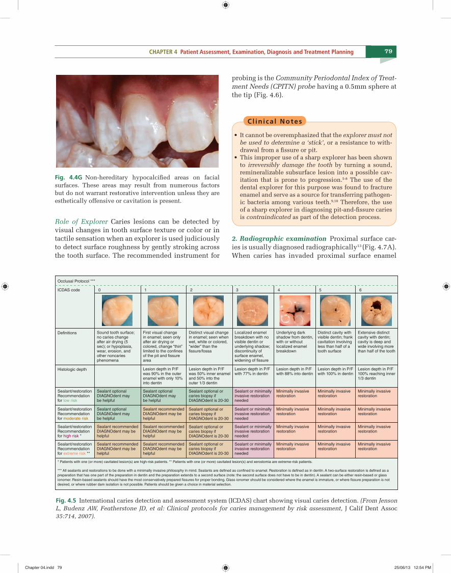
Fig. 4.4G Non-hereditary hypocalcifi ed areas on facial surfaces. These areas may result from numerous factors but do not warrant restorative intervention unless they are esthetically offensive or cavitation is present.
Occlusal Protocol ***
ICDAS code
Definitions
Histologic depth
Sealant/restorationRecommendation for low risk
Sealant/restorationRecommendation for moderate risk
Sealant/restorationRecommendation for extreme risk **
Sealant/restorationRecommendation for high risk *
0 1 2 3 4 5 6
Sound tooth surface;no caries changeafter air drying (5sec); or hypoplasia,wear, erosion, andother noncariesphenomena
Sealant optionalDIAGNOdent maybe helpful
Sealant optionalDIAGNOdent maybe helpful
Sealant optionalDIAGNOdent maybe helpful
Sealant recommendedDIAGNOdent may be helpful
Sealant recommendedDIAGNOdent may be helpful
Sealant recommendedDIAGNOdent may be helpful
Sealant recommendedDIAGNOdent may be helpful
Sealant optional or caries biopsy if DIAGNOdent is 20-30
Sealant optional or caries biopsy if DIAGNOdent is 20-30
Sealant optional or caries biopsy if DIAGNOdent is 20-30
Sealant optional or caries biopsy if DIAGNOdent is 20-30
Sealant recommendedDIAGNOdent may be helpful
First visual changein enamel; seen onlyafter air drying or colored, change “thin”limited to the confinesof the pit and fissure area
Lesion depth in P/Fwas 90% in the outer enamel with only 10%into dentin
Distinct visual changein enamel; seen whenwet, white or colored,“wider” than the fissure/fossa
Lesion depth in P/Fwas 50% inner enamel and 50% into theouter 1/3 dentin
Localized enamelbreakdown with novisible dentin orunderlying shadow;discontinuity ofsurface enamel, widening of fissure
Lesion depth in P/Fwith 77% in dentin
Sealant or minimallyinvasive restorationneeded
Sealant or minimallyinvasive restorationneeded
Sealant or minimallyinvasive restorationneeded
Sealant or minimallyinvasive restorationneeded
Minimally invasiverestoration
Minimally invasiverestoration
Minimally invasiverestoration
Minimally invasiverestoration
Minimally invasiverestoration
Minimally invasiverestoration
Minimally invasiverestoration
Minimally invasiverestoration
Minimally invasiverestoration
Minimally invasiverestoration
Minimally invasiverestoration
Minimally invasiverestoration
Underlying darkshadow from dentin,with or without localized enamelbreakdown
Lesion depth in P/Fwith 88% into dentin
Distinct cavity withvisible dentin; frankcavitation involvingless than half of a tooth surface
Lesion depth in P/Fwith 100% in dentin
Extensive distinctcavity with dentin;cavity is deep andwide involving morethan half of the tooth
Lesion depth in P/F100% reaching inner1/3 dentin
* Patients with one (or more) cavitated lesion(s) are high-risk patients. ** Patients with one (or more) cavitated lesion(s) and xerostomia are extreme-risk patients.
*** All sealants and restorations to be done with a minimally invasive philosophy in mind. Sealants are defined as confined to enamel. Restoration is defined as in dentin. A two-surface restoration is defined as apreparation that has one part of the preparation in dentin and the preparation extends to a second surface (note: the second surface does not have to be in dentin). A sealant can be either resin-based or glassionomer. Resin-based sealants should have the most conservatively prepared fissures for proper bonding. Glass ionomer should be considered where the enamel is immature, or where fissure preparation is not desired, or where rubber dam isolation is not possible. Patients should be given a choice in material selection.
Fig. 4.5 International caries detection and assessment system (ICDAS) chart showing visual caries detection. (From Jenson L, Budenz AW, Featherstone JD, et al: Clinical protocols for caries management by risk assessment, J Calif Dent Assoc 35:714, 2007).
Role of Explorer Caries lesions can be detected by visual changes in tooth surface texture or color or in tactile sensation when an explorer is used judiciously to detect surface roughness by gently stroking across the tooth surface. The recommended instrument for
Chapter 04.indd 79Chapter 04.indd 79 25/06/13 12:54 PM25/06/13 12:54 PM
C H A P T E R
7
111
Instruments and Equipment for Tooth Preparation
“A man who works with his hands is a … Labourer A man who works with hands and his brain is a … Craftsman A man who works with his hands and his brain and his heart is an … Artist.”
—LOUIS NIZER
Hand Instruments for Cutting
Removal and shaping of tooth structure are essential aspects of restorative dentistry. Modern high-speed equipment has eliminated the need for many hand instruments for tooth preparation. Nevertheless, hand instruments remain an essential part of the ar-mamentarium for restorative dentistry.
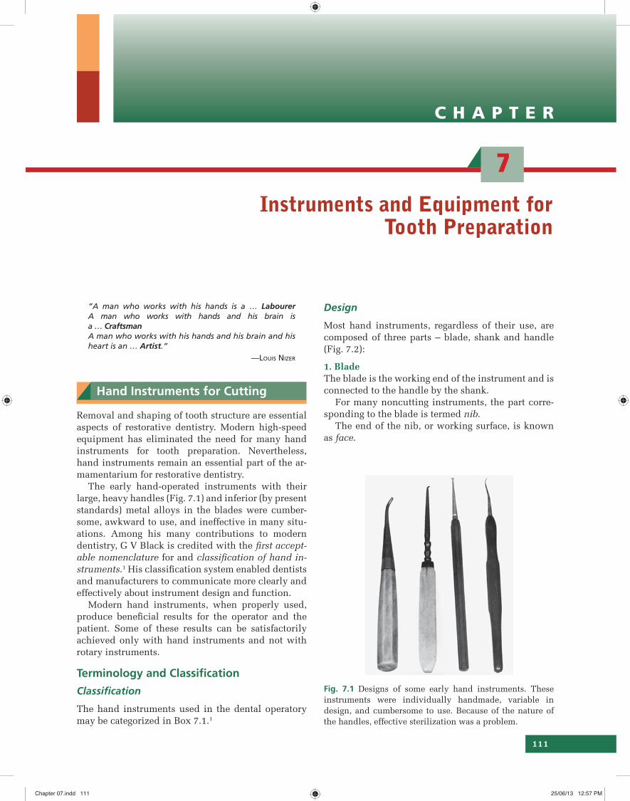
The early hand-operated instruments with their large, heavy handles (Fig. 7.1) and inferior (by present standards) metal alloys in the blades were cumber-some, awkward to use, and ineffective in many situ-ations. Among his many contributions to modern dentistry, G V Black is credited with the fi rst accept-able nomenclature for and classifi cation of hand in-struments.1 His classifi cation system enabled dentists and manufacturers to communicate more clearly and effectively about instrument design and function.
Modern hand instruments, when properly used, produce benefi cial results for the operator and the patient. Some of these results can be satisfactorily achieved only with hand instruments and not with rotary instruments.
Terminology and Classifi cation
Classifi cation
The hand instruments used in the dental operatory may be categorized in Box 7.1.1
Design
Most hand instruments, regardless of their use, are composed of three parts – blade, shank and handle (Fig. 7.2):
1. BladeThe blade is the working end of the instrument and is connected to the handle by the shank.
For many noncutting instruments, the part corre-sponding to the blade is termed nib.
The end of the nib, or working surface, is known as face.
Fig. 7.1 Designs of some early hand instruments. These instruments were individually handmade, variable in design, and cumbersome to use. Because of the nature of the handles, effective sterilization was a problem.
Chapter 07.indd 111Chapter 07.indd 111 25/06/13 12:57 PM25/06/13 12:57 PM
126 Sturdevant’s Art and Science of Operative Dentistry
Cl in i ca l Notes
Runout is the more signifi cant term clinically because it is the primary cause of vibration during cutting and is the factor that determines the minimum diameter of the hole that can be prepared by a given bur. Because of runout errors, burs normally cut holes measurably larger than the head diameter.
Bur Blade Design
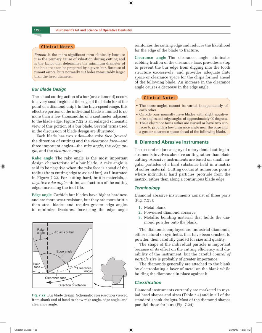
The actual cutting action of a bur (or a diamond) occurs in a very small region at the edge of the blade (or at the point of a diamond chip). In the high-speed range, this effective portion of the individual blade is limited to no more than a few thousandths of a centimeter adjacent to the blade edge. Figure 7.22 is an enlarged schematic view of this portion of a bur blade. Several terms used in the discussion of blade design are illustrated.
Each blade has two sides—the rake face (toward the direction of cutting) and the clearance face—and three important angles—the rake angle, the edge an-gle, and the clearance angle.
Rake angle The rake angle is the most important design characteristic of a bur blade. A rake angle is said to be negative when the rake face is ahead of the radius (from cutting edge to axis of bur), as illustrated in Figure 7.22. For cutting hard, brittle materials, a negative rake angle minimizes fractures of the cutting edge, increasing the tool life.
Edge angle Carbide bur blades have higher hardness and are more wear-resistant, but they are more brittle than steel blades and require greater edge angles to minimize fractures. Increasing the edge angle
reinforces the cutting edge and reduces the likelihood for the edge of the blade to fracture.
Clearance angle The clearance angle eliminates rubbing friction of the clearance face, provides a stop to prevent the bur edge from digging into the tooth structure excessively, and provides adequate fl ute space or clearance space for the chips formed ahead of the following blade. An increase in the clearance angle causes a decrease in the edge angle.
Cl in i ca l Notes
• The three angles cannot be varied independently of each other.
• Carbide burs normally have blades with slight negative rake angles and edge angles of approximately 90 degrees.
• Their clearance faces either are curved or have two sur-faces to provide a low clearance angle near the edge and a greater clearance space ahead of the following blade.
II. Diamond Abrasive Instruments
The second major category of rotary dental cutting in-struments involves abrasive cutting rather than blade cutting. Abrasive instruments are based on small, an-gular particles of a hard substance held in a matrix of softer material. Cutting occurs at numerous points where individual hard particles protrude from the matrix, rather than along a continuous blade edge.
Terminology
Diamond abrasive instruments consist of three parts (Fig. 7.23):
1. Metal blank 2. Powdered diamond abrasive 3. Metallic bonding material that holds the dia-
mond powder onto the blank.
The diamonds employed are industrial diamonds, either natural or synthetic, that have been crushed to powder, then carefully graded for size and quality.
The shape of the individual particle is important because of its effect on the cutting effi ciency and du-rability of the instrument, but the careful control of particle size is probably of greater importance.
The diamonds generally are attached to the blank by electroplating a layer of metal on the blank while holding the diamonds in place against it.
Classifi cation
Diamond instruments currently are marketed in myr-iad head shapes and sizes (Table 7.4) and in all of the standard shank designs. Most of the diamond shapes parallel those for burs (Fig. 7.24).
To axis of bur
Edge angle
Clearanceangle
Clearance face
Rakeface
Rakeangle
Direction of rotation
Fig. 7.22 Bur blade design. Schematic cross-section viewed from shank end of head to show rake angle, edge angle, and clearance angle.
Chapter 07.indd 126Chapter 07.indd 126 25/06/13 12:57 PM25/06/13 12:57 PM
C H A P T E R
9
159
Fundamentals of Tooth Preparation and Pulp Protection
“Success is neither magical nor mysterious…Success is the natural consequence of consistently applying the basic fundamentals.”
—JIM ROHN
In the past, most restorative treatments were for car-ies, and the term cavity was used to describe a car-ies lesion that had progressed to the point that part of the tooth structure had been destroyed. The tooth was cavitated (a breach in the surface integrity of the tooth) and was referred to as a cavity. Likewise, when the affected tooth was treated, the cutting or prepa-ration of the remaining tooth structure (to receive a restorative material) was referred to as cavity prepa-ration. Currently, many indications for treatment are not related to carious destruction, and the prepara-tion of the tooth no longer is referred to as cavity preparation, but as tooth preparation.
Much of the scientifi c foundation of tooth prepara-tion techniques was presented by Black.1 Modifi ca-tions of Black’s principles of tooth preparation have resulted from the infl uence of: 2–6 • Concepts professed by Bronner, Markley, J Stur-devant, Sockwell, and C Sturdevant. • Improvements in restorative materials, instru-ments, and techniques. • Increased knowledge and application of preventive measures for caries.
Tooth Preparation
Tooth preparation is defi ned as the mechanical alter-ation of a defective, injured, or diseased tooth such that placement of restorative material re-establishes normal form and function, including esthetic correc-tions, where indicated.
Conventional Preparation
In the past, most tooth preparations were precise pro-cedures, usually resulting in uniform depths, particu-lar wall forms, and specifi c marginal confi gurations. Such precise preparations are still required for amal-gam, cast metal, and ceramic restorations and may be considered conventional preparations. Conventional preparations require specifi c wall forms, depths, and marginal forms because of the properties of the re-storative material.
Modifi ed Preparation
The use of adhesive restorations, primarily composites and glass ionomers, has allowed a reduced degree of precision of tooth preparations. Many composite res-torations may require only the removal of the defect (caries, fracture, or defective restorative material) and friable tooth structure for tooth preparation, without specifi c uniform depths, wall designs, retentive fea-tures or marginal forms. This simplifi cation of proce-dures results in a modifi ed preparation and is possible because of the physical properties of the composite material and the strong bond obtained between the composite and the tooth structure (Table 9.1).
Much of this chapter presents information about the conventional tooth preparations because of the specifi city required. The fundamental concepts relat-ing to conventional and modifi ed tooth preparation are the same:
1. All unsupported enamel tooth structures are normally removed.
2. Fault, defect, or caries is removed. 3. Remaining tooth structure is left as strong as
possible.
Chapter 09.indd 159Chapter 09.indd 159 25/06/13 1:08 PM25/06/13 1:08 PM
165CHAPTER 9 Fundamentals of Tooth Preparation and Pulp Protection
ii. These enamel rods are buttressed on the preparation side by progressively shorter rods whose outer ends have been cut off but whose inner ends are on sound dentin (Fig. 9.5B). Because enamel rods usually are perpendicular to the enamel surface, the strongest enamel margin results in a cavosurface angle greater than 90 degrees (see Fig. 9.4).
2. An enamel margin composed of full-length rods that are on sound dentin but are not buttressed tooth-side by shorter rods also on sound dentin is termed strong. Generally, this margin results in a 90 degree cavosurface angle.
3. An enamel margin composed of rods that do not run uninterrupted from the surface to sound den-tin is termed unsupported. Usually, this weak enamel margin either has a cavosurface angle less than 90 degrees or has no dentinal support.
Classifi cation of Tooth Preparations
Classifi cation of tooth preparations according to the diseased anatomic areas involved and by the associ-ated type of treatment was presented by Black.1 These classifi cations were designated as class I, class II, class III, class IV, and class V. Since Black’s original classi-fi cation, an additional class has been added, class VI.
Class I Preparations
All pit-and-fi ssure preparations are termed class I. These include preparations on:
1. Occlusal surfaces of premolars and molars 2. Occlusal two-thirds of the facial and lingual sur-
faces of molars 3. Lingual surfaces of maxillary incisors.
Class II Preparations
Preparations involving the proximal surfaces of pos-terior teeth are termed class II.
Class III Preparations
Preparations involving the proximal surfaces of an-terior teeth that do not include the incisal angle are termed class III.
Class IV Preparations
Preparations involving the proximal surfaces of an-terior teeth that include the incisal edge are termed class IV.
Class V Preparations
Preparations on the gingival third of the facial or lin-gual surfaces of all teeth are termed class V.
Class VI Preparations
Preparations on the incisal edges of anterior teeth or the occlusal cusp tips of posterior teeth are termed class VI.
Stages of Tooth Preparation
The tooth preparation procedure is divided into two stages, each with several steps. Each stage should be thoroughly understood, and each step should be accom-plished as perfectly as possible. The stages are present-ed in the sequence in which they should be followed if consistent, ideal results are to be obtained. The stages and steps in tooth preparation are listed in Box 9.1.
Initial Tooth Preparation Stage
Initial tooth preparation involves the extension of the external walls of the preparation at a specifi ed, limited depth so as to provide access to the caries or defect and to reach peripheral sound tooth structure. The place-ment and orientation of the preparation walls are de-signed to resist fracture of the tooth or restorative mate-rial from masticatory forces principally directed with the long axis of the tooth and to retain the restorative material in the tooth (except for a class V preparation).
Step 1: Outline Form and Initial Depth
The fi rst step in initial tooth preparation is determin-ing and developing the outline form while establish-ing the initial depth.
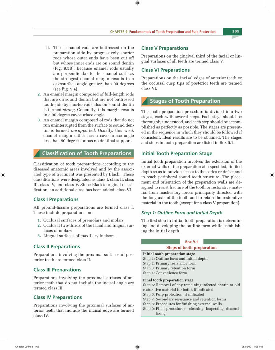
Box 9.1
Steps of tooth preparation
Initial tooth preparation stageStep 1: Outline form and initial depthStep 2: Primary resistance formStep 3: Primary retention formStep 4: Convenience form
Final tooth preparation stageStep 5: Removal of any remaining infected dentin or old restorative material (or both), if indicatedStep 6: Pulp protection, if indicatedStep 7: Secondary resistance and retention formsStep 8: Procedures for fi nishing external wallsStep 9: Final procedures—cleaning, inspecting, desensi-
tizing
Chapter 09.indd 165Chapter 09.indd 165 25/06/13 1:08 PM25/06/13 1:08 PM
166 Sturdevant’s Art and Science of Operative Dentistry
Defi nitionEstablishing the outline form means:
1. Placing the preparation margins in the positions they will occupy in the fi nal preparation except for fi nishing enamel walls and margins.
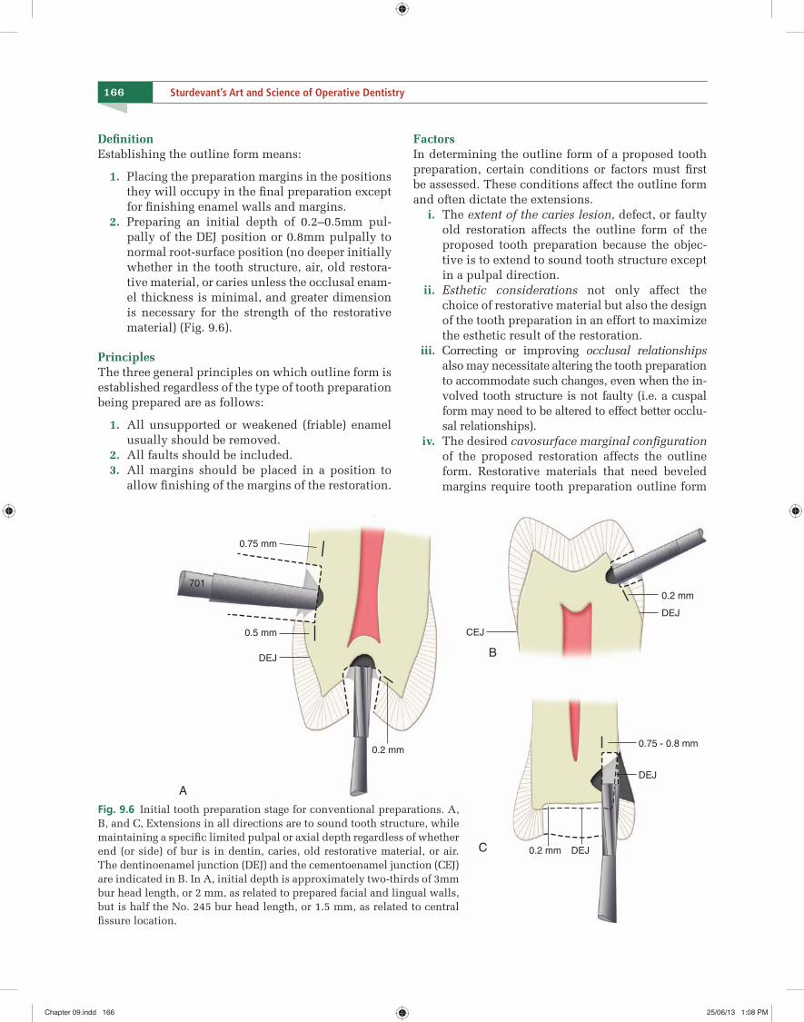
2. Preparing an initial depth of 0.2–0.5mm pul-pally of the DEJ position or 0.8mm pulpally to normal root-surface position (no deeper initially whether in the tooth structure, air, old restora-tive material, or caries unless the occlusal enam-el thickness is minimal, and greater dimension is necessary for the strength of the restorative material) (Fig. 9.6).
PrinciplesThe three general principles on which outline form is established regardless of the type of tooth preparation being prepared are as follows:
1. All unsupported or weakened (friable) enamel usually should be removed.
2. All faults should be included. 3. All margins should be placed in a position to
allow fi nishing of the margins of the restoration.
FactorsIn determining the outline form of a proposed tooth preparation, certain conditions or factors must fi rst be assessed. These conditions affect the outline form and often dictate the extensions. i. The extent of the caries lesion, defect, or faulty
old restoration affects the outline form of the proposed tooth preparation because the objec-tive is to extend to sound tooth structure except in a pulpal direction.
ii. Esthetic considerations not only affect the choice of restorative material but also the design of the tooth preparation in an effort to maximize the esthetic result of the restoration.
iii. Correcting or improving occlusal relationships also may necessitate altering the tooth preparation to accommodate such changes, even when the in-volved tooth structure is not faulty (i.e. a cuspal form may need to be altered to effect better occlu-sal relationships).
iv. The desired cavosurface marginal confi guration of the proposed restoration affects the outline form. Restorative materials that need beveled margins require tooth preparation outline form
A
B
C
0.75 mm
0.2 mm
0.2 mm
0.2 mm
0.75 - 0.8 mm
0.5 mm
DEJ
DEJ
701
DEJ
DEJ
CEJ
Fig. 9.6 Initial tooth preparation stage for conventional preparations. A, B, and C, Extensions in all directions are to sound tooth structure, while maintaining a specifi c limited pulpal or axial depth regardless of whether end (or side) of bur is in dentin, caries, old restorative material, or air. The dentinoenamel junction (DEJ) and the cementoenamel junction (CEJ) are indicated in B. In A, initial depth is approximately two-thirds of 3mm bur head length, or 2 mm, as related to prepared facial and lingual walls, but is half the No. 245 bur head length, or 1.5 mm, as related to central fi ssure location.
Chapter 09.indd 166Chapter 09.indd 166 25/06/13 1:08 PM25/06/13 1:08 PM
167CHAPTER 9 Fundamentals of Tooth Preparation and Pulp Protection
extensions that must anticipate the fi nal cavo-surface position and form after the bevels have been placed.
FeaturesGenerally, the typical features of establishing proper outline form and initial depth are:
1. Preserving cuspal strength 2. Preserving marginal ridge strength 3. Minimizing faciolingual extensions 4. Connecting two close (<0.5mm apart) defects or
tooth preparations 5. Restricting the depth of the preparation into dentin.
Outline form and initial depth for pit-and-fi ssure lesionsOutline form and initial depth in pit-and-fissure preparations are controlled by three factors: 1. Extent to which the enamel has been involved
by the carious process 2. Extensions that must be made along the fissures
to achieve sound and smooth margins 3. Limited bur depth related to the tooth’s original
surface (real or visualized if missing because of disease or defect) while extending the preparation to sound external walls that have a pulpal depth of approximately 1.5–2mm and usually a maximum depth into dentin of 0.2mm (see Fig.9.6A and B).
Rules for establishing outline form for pit-and-fi ssure tooth preparation
1. Extend the preparation margin until sound tooth structure is obtained, and no unsupported or weakened enamel remains.
2. Avoid terminating the margin on extreme emi-nences, such as cusp heights or ridge crests.
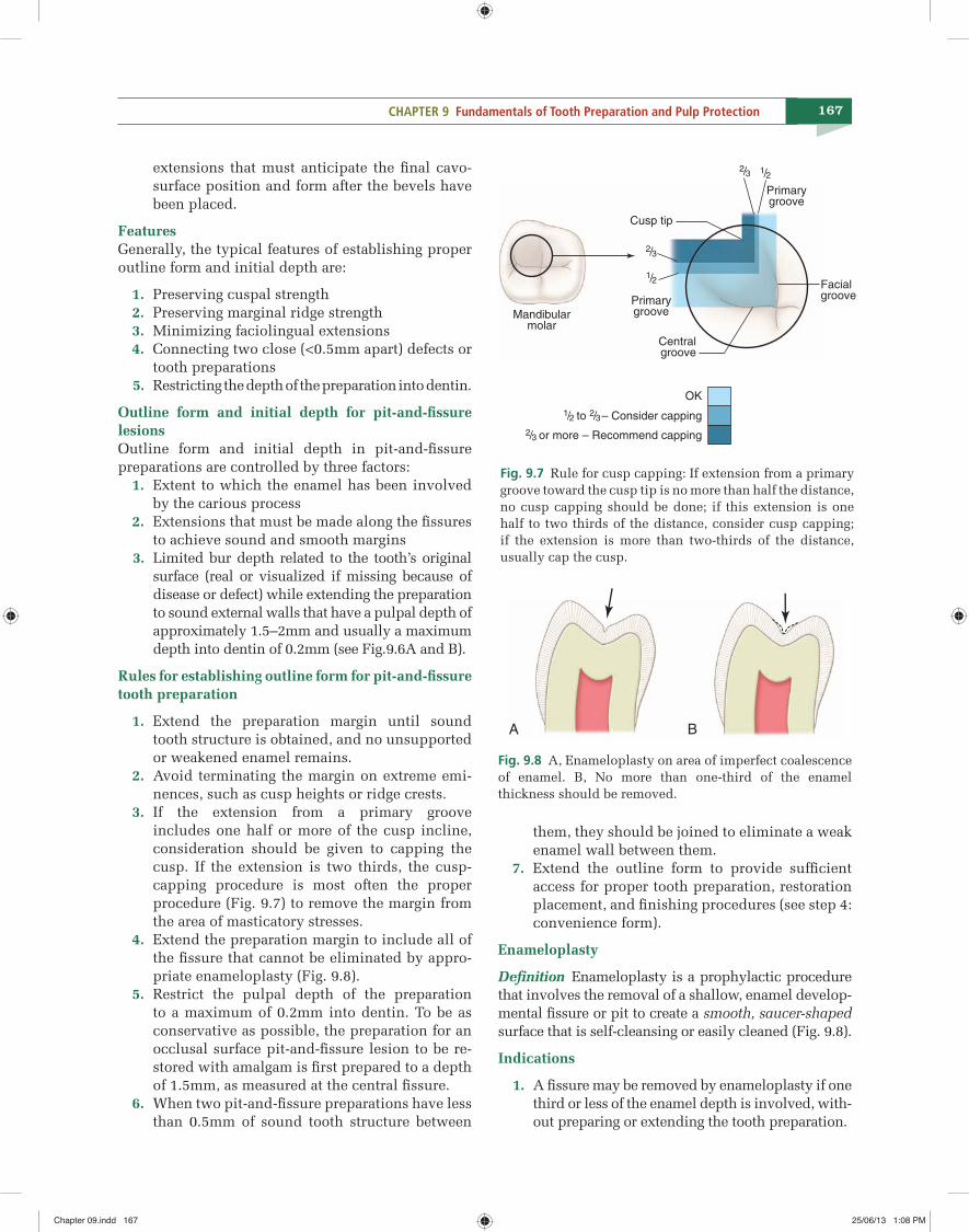
3. If the extension from a primary groove includes one half or more of the cusp incline, consideration should be given to capping the cusp. If the extension is two thirds, the cusp-capping procedure is most often the proper procedure (Fig. 9.7) to remove the margin from the area of masticatory stresses.
4. Extend the preparation margin to include all of the fissure that cannot be eliminated by appro-priate enameloplasty (Fig. 9.8).
5. Restrict the pulpal depth of the preparation to a maximum of 0.2mm into dentin. To be as conservative as possible, the preparation for an occlusal surface pit-and-fissure lesion to be re-stored with amalgam is first prepared to a depth of 1.5mm, as measured at the central fissure.
6. When two pit-and-fissure preparations have less than 0.5mm of sound tooth structure between
them, they should be joined to eliminate a weak enamel wall between them.
7. Extend the outline form to provide sufficient access for proper tooth preparation, restoration placement, and finishing procedures (see step 4: convenience form).
Enameloplasty
Defi nition Enameloplasty is a prophylactic procedure that involves the removal of a shallow, enamel develop-mental fi ssure or pit to create a smooth, saucer-shaped surface that is self-cleansing or easily cleaned (Fig. 9.8).
Indications
1. A fi ssure may be removed by enameloplasty if one third or less of the enamel depth is involved, with-out preparing or extending the tooth preparation.
1/2
1/2
Primarygroove
PrimarygrooveMandibular
molar
Centralgroove
Cusp tip
Facialgroove
2/3
2/3
OK
1/2 to 2/3 – Consider capping
2/3 or more – Recommend capping
Fig. 9.7 Rule for cusp capping: If extension from a primary groove toward the cusp tip is no more than half the distance, no cusp capping should be done; if this extension is one half to two thirds of the distance, consider cusp capping; if the extension is more than two-thirds of the distance, usually cap the cusp.
A B
Fig. 9.8 A, Enameloplasty on area of imperfect coalescence of enamel. B, No more than one-third of the enamel thickness should be removed.
Chapter 09.indd 167Chapter 09.indd 167 25/06/13 1:08 PM25/06/13 1:08 PM
C H A P T E R
10
179
Fundamental Concepts of Enamel and Dentin Adhesion
“Imagination is the beginning of creation…you imagine what you desire…You will what you imagine and at last …you create what you will.”
—GEORGE BERNARD SHAW
Basic Concepts of Adhesion
Defi nitions
The word adhesion comes from the Latin adhaerere (‘to stick to’). Adhesion is defi ned as the state in which two surfaces are held together by interfacial forces, which may consist of valence forces, or in-terlocking forces or both (The American Society for Testing and Materials [Specifi cation D 907]).1
Adhesive is a material, frequently a viscous fl uid that joins two substrates together by solidifying, re-sisting separation and transferring a load from one surface to the other. Adhesive strength is the measure of the load-bearing capacity of an adhesive joint.2
Mechanisms of Dental Adhesion
In dentistry, bonding of resin-based materials to tooth structure is a result of four possible mechanisms:3
1. Mechanical adhesion: Interlocking of the ad-hesive with irregularities in the surface of the substrate, or adherend. This would involve the penetration of adhesive resin and formation of resin tags within the tooth surface.
2. Adsorption adhesion: Chemical bonding be-tween the adhesive and the adherend; the forces involved may be primary valence forces (ionic and covalent) or secondary valence forces (hy-drogen bonds, dipole interaction, or van der
Waals). This would involve the chemical bond-ing to the inorganic component (hydroxyapa-tite) or organic components (mainly type I col-lagen) of tooth structure.
3. Diffusion adhesion: Interlocking between mo-bile molecules, such as the adhesion of two pol-ymers through diffusion of polymer chain ends across an interface. This would involve the pre-cipitation of substances on the tooth surfaces to which resin monomers can bond mechanically or chemically.
4. A combination of the previous three mecha-nisms.
Criteria for Optimal Adhesion
For good adhesion to take place, fi ve fundamental at-tributes which are required are illustrated in Fig. 10.1.
Indications for Adhesive Dentistry
The availability of new scientifi c information on the etiology, diagnosis, and treatment of carious lesions and the introduction of reliable adhesive restorative materials have substantially reduced the need for ex-tensive tooth preparations. Adhesive techniques also allow more conservative tooth preparations, less reli-ance on macro-mechanical retention, and less remov-al of unsupported enamel. With improvements in materials, indications for resin-based materials have progressively shifted from the anterior segment only to posterior teeth as well.
Adhesive restorative techniques currently are used for the following indications:
1. Restore class I, II, III, IV, V, and VI carious or traumatic defects
Chapter 10.indd 179Chapter 10.indd 179 25/06/13 1:10 PM25/06/13 1:10 PM
186 Sturdevant’s Art and Science of Operative Dentistry
Classifi cation of Dentinal Adhesives
We can divide the chronology of development of dentinal adhesives into historical and current op-tions (Table 10.1). A complete listing of the chemi-cal names mentioned in this chapter is provided in Table 10.2.
I. Historical Strategies
i. First Generation (1965)
Chemical Surface-active co-monomer NPG-GMA26,56
Mechanism of action Theoretically, this co-monomer could chelate with calcium on the tooth surface to generate wa-ter-resistant chemical bonds of resin to dentinal calcium.57,58
Brand Name Cervident (S S White Burs, Inc, Lakewood, NJ)
Bond Strength Only 2–3 MPa.59
Clinical resultCervident had poor clinical results when used to re-store noncarious cervical lesions without mechanical retention.60
ii. Second Generation (1978)
Chemical It was a phosphate-ester material (phenyl-P and hy-droxyethyl methacrylate [HEMA] in ethanol).
Mechanism of action It was based on the polar interaction between nega-tively charged phosphate groups in the resin and positively charged calcium ions in the smear layer.59
Brand names
1. Clearfi l Bond System F (Kuraray Co, Ltd, Osaka, Japan)
2. Scotchbond (3M EPSE Dental Products, St. Paul, MN)
3. Bondlite (Kerr Corporation, Orange, CA) 4. Prisma Universal Bond (DENTSPLY Caulk, Mil-
ford, DE).
Bond strength Only 1–5 MPa.4,43
Clinical result The in vitro performance of second-generation adhe-sives after 6 months was unacceptable.61 The bonding material tended to peel from the dentin surface after water storage.61,62 The in vivo performance of these materials was found to be clinically unacceptable 2 years after placement in cervical tooth preparations without additional retention.63,64
TABLE 10.1
Classifi cation of dentinal adhesives1. Historical strategies:
i. First generation (1965) ii. Second generation (1978) iii. Third generation (1984)
2. Current strategies: i. Etch and rinse adhesives
a. Three step—etch and rinse adhesive (fourth generation)
b. Two step—etch and rinse adhesive (fi fth generation)
ii. Self-etch adhesivesa. Two component—self-etch adhesive (sixth
generation)— Two step—two component—self-etch
adhesive— One step—two component—self-etch
adhesiveb. Single component—one step—self-etch
adhesive (seventh generation)
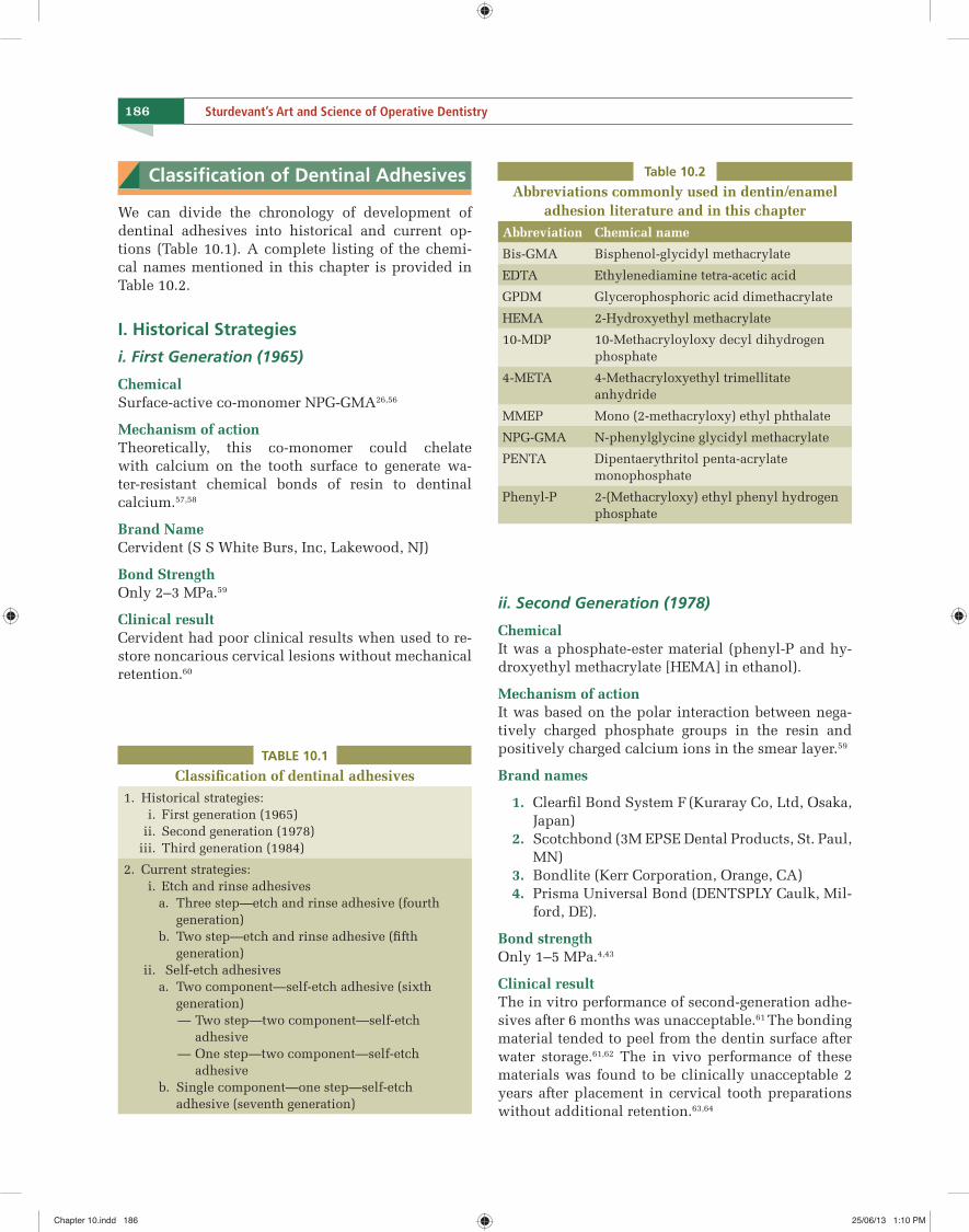
Table 10.2
Abbreviations commonly used in dentin/enamel adhesion literature and in this chapter
Abbreviation Chemical name
Bis-GMA Bisphenol-glycidyl methacrylate
EDTA Ethylenediamine tetra-acetic acid
GPDM Glycerophosphoric acid dimethacrylate
HEMA 2-Hydroxyethyl methacrylate
10-MDP 10-Methacryloyloxy decyl dihydrogen phosphate
4-META 4-Methacryloxyethyl trimellitate anhydride
MMEP Mono (2-methacryloxy) ethyl phthalate
NPG-GMA N-phenylglycine glycidyl methacrylate
PENTA Dipentaerythritol penta-acrylate monophosphate
Phenyl-P 2-(Methacryloxy) ethyl phenyl hydrogen phosphate
Chapter 10.indd 186Chapter 10.indd 186 25/06/13 1:10 PM25/06/13 1:10 PM
187CHAPTER 10 Fundamental Concepts of Enamel and Dentin Adhesion
iii. Third Generation (1984)
ChemicalIt was a phosphate-based material containing HEMA and a 10-carbon molecule known as 10-MDP, which included long hydrophobic and short hydrophilic components.57
Mechanism of action
1. The concept of phosphoric acid-etching of den-tin before application of a phosphate ester-type bonding agent was introduced by Fusayama et al in 1979.65 Clearfi l New Bond (Kuraray, Japan) was the only third generation bonding agent to follow the etched dentin philosophy.
2. Most of the other third-generation materials were designed not to remove the entire smear layer but, rather, to modify it and allow the penetration of acidic monomers, such as phenyl-P or PENTA.
Brand names
1. Clearfi l New Bond (Kuraray Co, Ltd, Osaka, Japan)
2. Scotchbond 2 (3M ESPE Dental Products)
Clinical resultClinical results were mixed, with some reports of good performance and some reports of poor performance.63,64
II. Current Strategies for Resin–Dentin Bonding
i. Etch and Rinse Adhesives
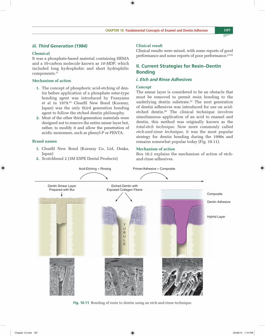
Concept The smear layer is considered to be an obstacle that must be removed to permit resin bonding to the underlying dentin substrate.42 The next generation of dentin adhesives was introduced for use on acid-etched dentin.66 The clinical technique involves simultaneous application of an acid to enamel and dentin, this method was originally known as the total-etch technique. Now more commonly called etch-and-rinse technique, it was the most popular strategy for dentin bonding during the 1990s and remains somewhat popular today (Fig. 10.11).
Mechanism of actionBox 10.2 explains the mechanism of action of etch-and-rinse adhesives.
Primer/Adhesive + CompositeAcid-Etching + Rinsing
Composite
Dentin Adhesive
Hybrid Layer
TU
B
ULE
Etched Dentin with
Exposed Collagen Fibers
Dentin Smear Layer
Prepared with Bur
Fig. 10.11 Bonding of resin to dentin using an etch-and-rinse technique.
Chapter 10.indd 187Chapter 10.indd 187 25/06/13 1:10 PM25/06/13 1:10 PM
C H A P T E R
13
241
Class III and IV Direct Composite Restorations
“A thing of beauty is a joy forever.”—JOHN KEATS
Class III and IV Direct Composite Restorations
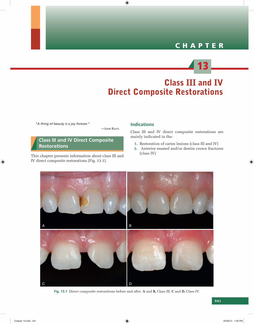
This chapter presents information about class III and IV direct composite restorations (Fig. 13.1).
Indications
Class III and IV direct composite restorations are mainly indicated in the:
1. Restoration of caries lesions (class III and IV) 2. Anterior enamel and/or dentin crown fractures
(class IV)
A B
C D
Fig. 13.1 Direct composite restorations before and after. A and B, Class III. C and D, Class IV.
Chapter 13.indd 241Chapter 13.indd 241 25/06/13 1:56 PM25/06/13 1:56 PM
251CHAPTER 13 Class III and IV Direct Composite Restorations
A B
C D
E F
G H
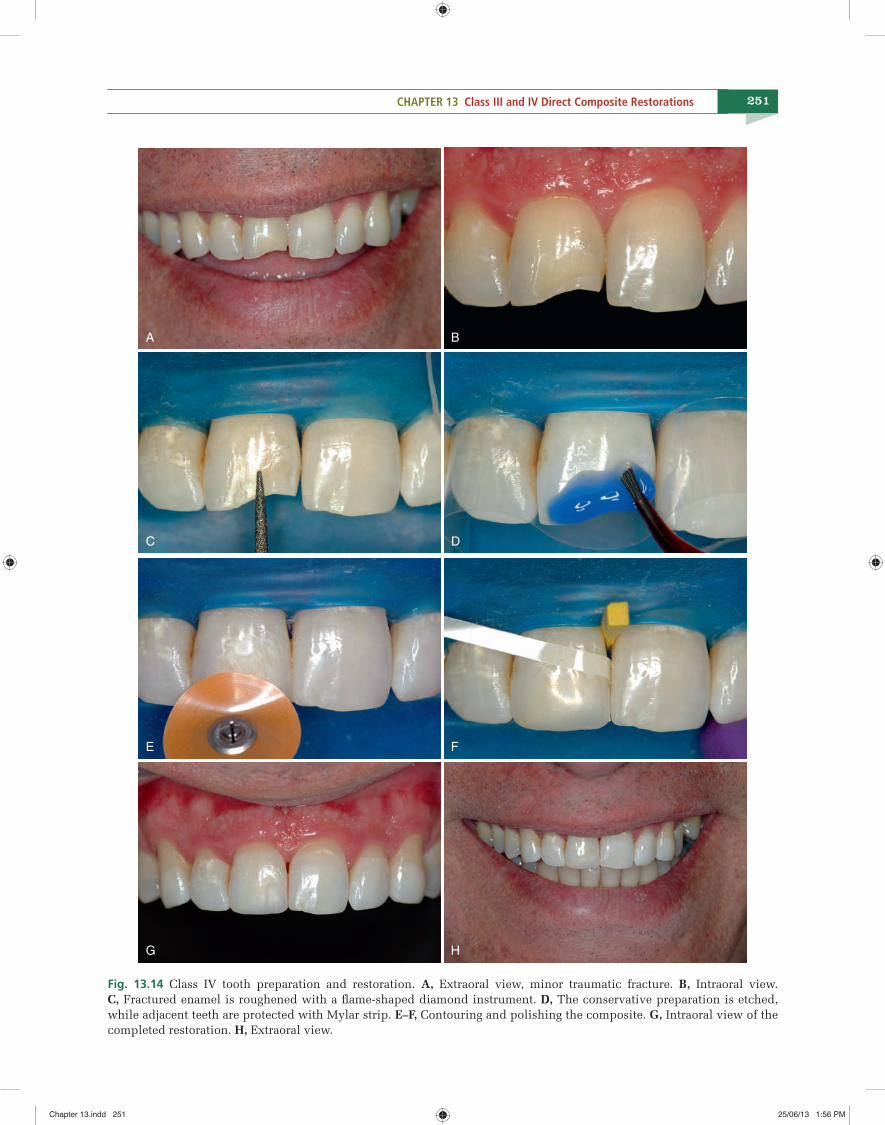
Fig. 13.14 Class IV tooth preparation and restoration. A, Extraoral view, minor traumatic fracture. B, Intraoral view. C, Fractured enamel is roughened with a fl ame-shaped diamond instrument. D, The conservative preparation is etched, while adjacent teeth are protected with Mylar strip. E–F, Contouring and polishing the composite. G, Intraoral view of the completed restoration. H, Extraoral view.
Chapter 13.indd 251Chapter 13.indd 251 25/06/13 1:56 PM25/06/13 1:56 PM
C H A P T E R
17
303
Additional Conservative Esthetic Procedures
“Beauty is harmony of all parts, in whatsoever subject it appears, fi tted together with such proportion and connection, that nothing could be added, diminished or altered…. but for the worse.”
—LEON BATTISTE ALBERTE (1610)
Signifi cant improvements in tooth-colored restora-tive materials and adhesive techniques have resulted in numerous conservative esthetic treatment possi-bilities. This chapter presents conservative esthetic procedures in the context of their clinical applica-tions.
Artistic Elements
In conservative esthetic dentistry certain basic artis-tic elements must be considered to ensure an optimal esthetic result. These elements include the following:
1. Shape or form 2. Symmetry and proportionality 3. Position and alignment 4. Surface texture 5. Color 6. Translucency.
I. Shape or Form
The shape of teeth largely determines their esthetic appearance. To achieve optimal dental esthetics, it is imperative that natural anatomic forms be achieved. Subtle variations in shape and contour produce very different appearances.
Cosmetic Contouring
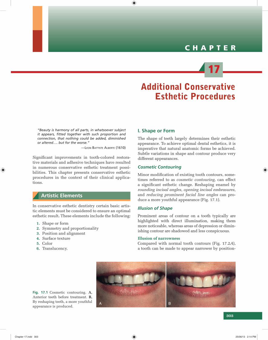
Minor modifi cation of existing tooth contours, some-times referred to as cosmetic contouring, can effect a signifi cant esthetic change. Reshaping enamel by rounding incisal angles, opening incisal embrasures, and reducing prominent facial line angles can pro-duce a more youthful appearance (Fig. 17.1).
Illusion of Shape
Prominent areas of contour on a tooth typically are highlighted with direct illumination, making them more noticeable, whereas areas of depression or dimin-ishing contour are shadowed and less conspicuous.
Illusion of narrowness Compared with normal tooth contours (Fig. 17.2A), a tooth can be made to appear narrower by position-
A B
Fig. 17.1 Cosmetic contouring. A, Anterior teeth before treatment. B, By reshaping teeth, a more youthful appearance is produced.
Chapter 17.indd 303Chapter 17.indd 303 25/06/13 2:14 PM25/06/13 2:14 PM
322 Sturdevant’s Art and Science of Operative Dentistry
Veneers
Defi nition A veneer is a layer of tooth-colored ma-terial that is applied to a tooth to restore localized or generalized defects and intrinsic discolorations (Fig.17-25).
Indications
Common indications for veneers include teeth with facial surfaces are as follows (Fig. 17.26): • Tooth malformation • Discolored teeth • Abraded or eroded facial surfaces • Faulty restorations.
Types of veneers
1. Based on the extent of the tooth involved, ve-neers can be classifi ed as:
i. Partial veneers: Partial veneers are in-dicated for the restoration of localized
defects or areas of intrinsic discoloration (Fig. 17.27).
ii. Full veneers: Full veneers are indicated for the restoration of generalized defects or ar-eas of intrinsic staining involving most of the facial surface of the tooth (Figs. 17.25 and17-28). Full veneers can be further sub-divided based on the preparation design (Fig. 17.27) as:a. Window preparationb. Butt joint incisal preparationc. Incisal overlap preparation.
2. Based on the type of material employed, veneers can be classifi ed as:
i. Directly applied composite veneer ii. Processed composite veneer iii. Porcelain or pressed ceramic veneer. 3. Based on the mode of fabrication veneers can be
classifi ed into: i. Direct veneers
a. Direct partial veneersb. Direct full veneers
A B
C D
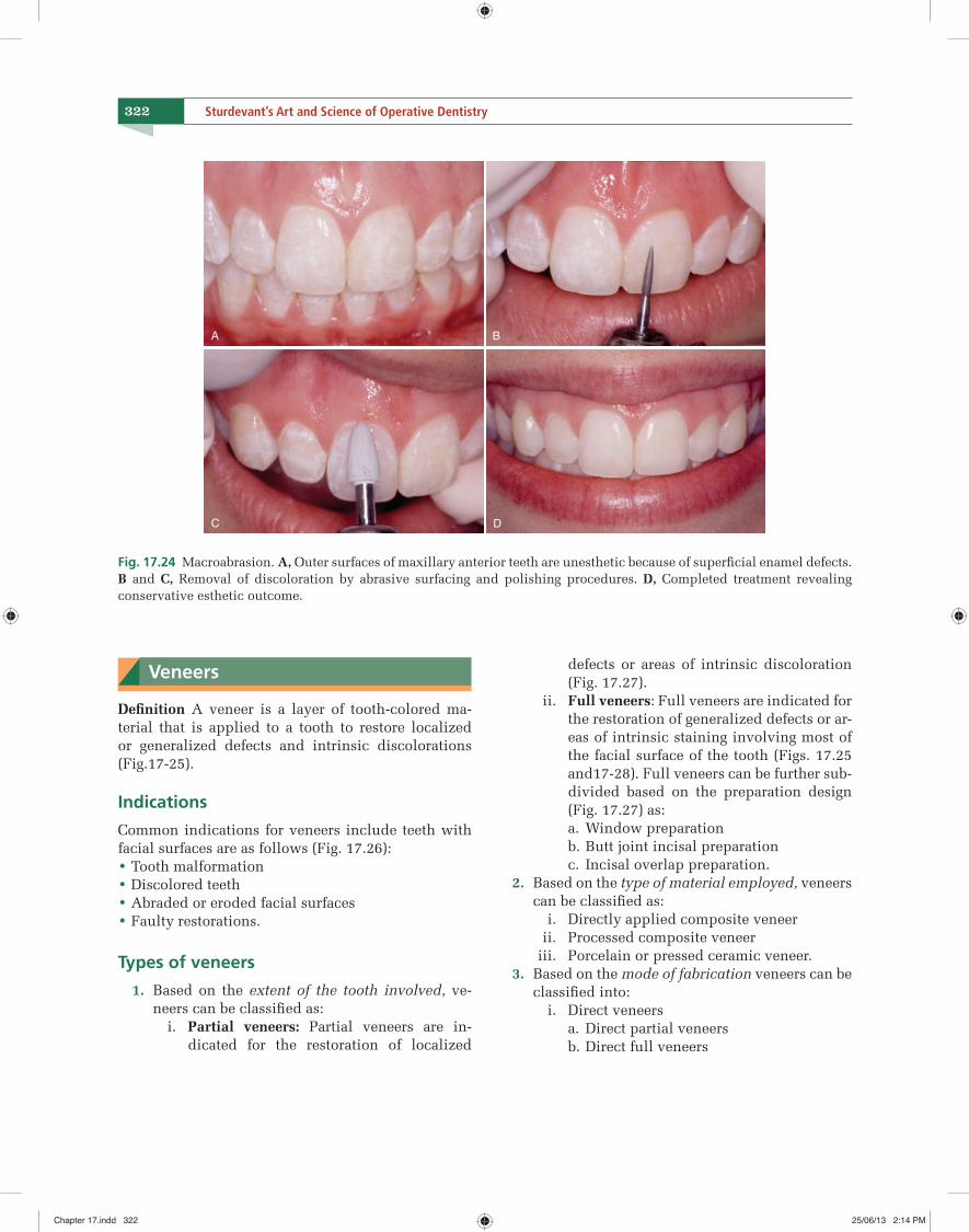
Fig. 17.24 Macroabrasion. A, Outer surfaces of maxillary anterior teeth are unesthetic because of superfi cial enamel defects. B and C, Removal of discoloration by abrasive surfacing and polishing procedures. D, Completed treatment revealing conservative esthetic outcome.
Chapter 17.indd 322Chapter 17.indd 322 25/06/13 2:14 PM25/06/13 2:14 PM
326 Sturdevant’s Art and Science of Operative Dentistry
Cl in i ca l Notes
• Although two appointments are required for indirect veneers, chair time is reduced because much of the work has been done in the laboratory.
• Excellent results can be obtained when proper clinical evaluation and careful operating procedures are fol-lowed.
• Indirect veneers are attached to the enamel by acid etching and bonding with light-cured resin cement.
1. No-prep Veneers
Concept One approach being used for indirect veneers is to place them on teeth with no tooth preparation.
Indications No-prep veneers are best used when teeth are inherent-ly undercontoured, when interdental spaces or open incisal embrasures are present, or when both condi-tions exist. Example of successful no-prep veneers fol-lowing these guidelines is seen in Figure 17.29.
Cl in i ca l Notes
• No-prep veneers can be problematic because of the fol-lowing reasons:
○ First, no-prep veneers are inherently made thinner and, consequently, are more prone to fracture, espe-cially during the try-in phase.
○ Second, for indirect no-prep veneers, interproximal areas are diffi cult to access for proper fi nishing.
○ Third, if case selection is not done properly and the teeth are already of normal contour, the resulting ve-neers inevitably will be overcontoured.
2. Etched Porcelain Veneers
Concept The preferred type of indirect veneer is the etched porcelain (i.e. feldspathic) veneer. Porcelain veneers etched with hydrofl uoric acid are capable of achiev-ing high bond strengths to the etched enamel via a resin-bonding medium.27–29 Etched porcelain veneers are highly esthetic, stain resistant, and periodontally compatible.
Clinical procedure
Step 1: Preoperative considerations
i. A consult appointment is always recommended for shade selection, intraoral photographs, and impressions for diagnostic models and occlusal records.
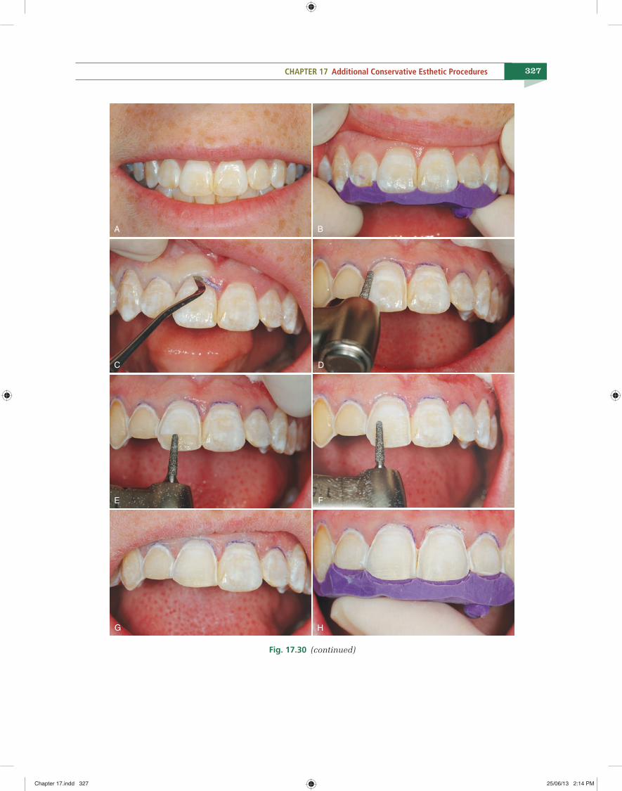
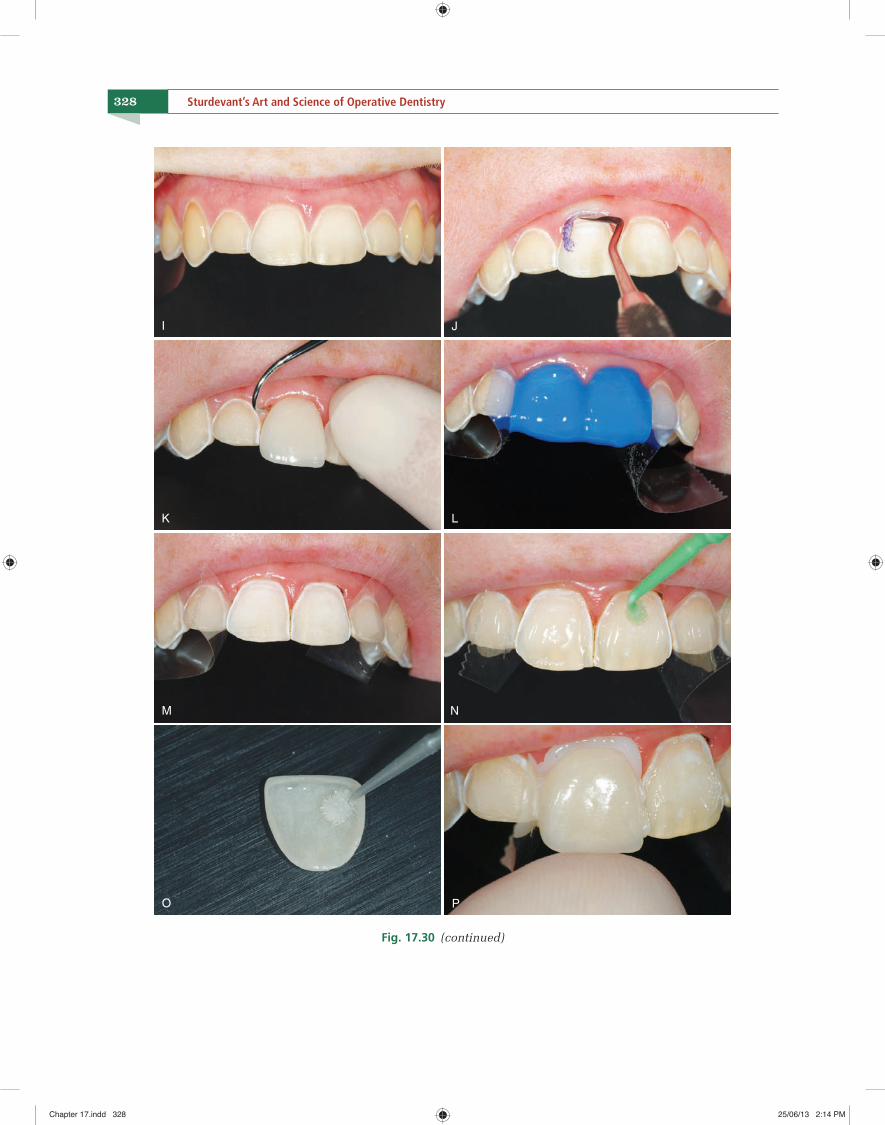
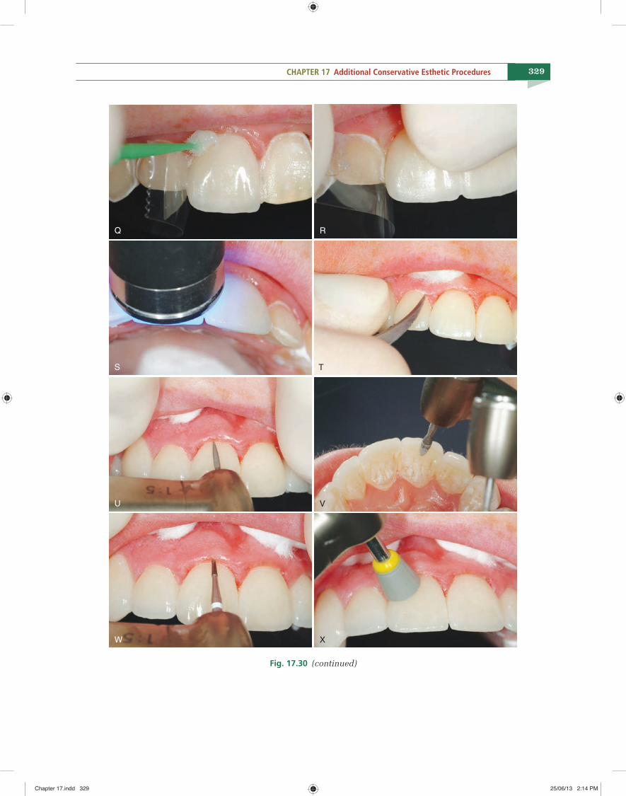
ii. An incisal reduction index is always recommend-ed to accurately gauge the amount of incisal re-duction during the preparation of teeth for etched porcelain veneers (Fig. 17.30B through H).
Step 2: InstrumentationThe veneer preparation is made with a tapered, rounded-end diamond instrument. A diamond with a tip diameter of 1.0–1.2 mm is recommended.
Step 3: Clinical considerations
i. The intraenamel preparations are made to a depth of approximately 0.5–0.75 mm midfacial-ly, diminishing to a depth of 0.3–0.5 mm along the gingival margins, depending on enamel thickness.
ii. Veneer interproximal margins should be located just facial to the proximal contacts.
BA
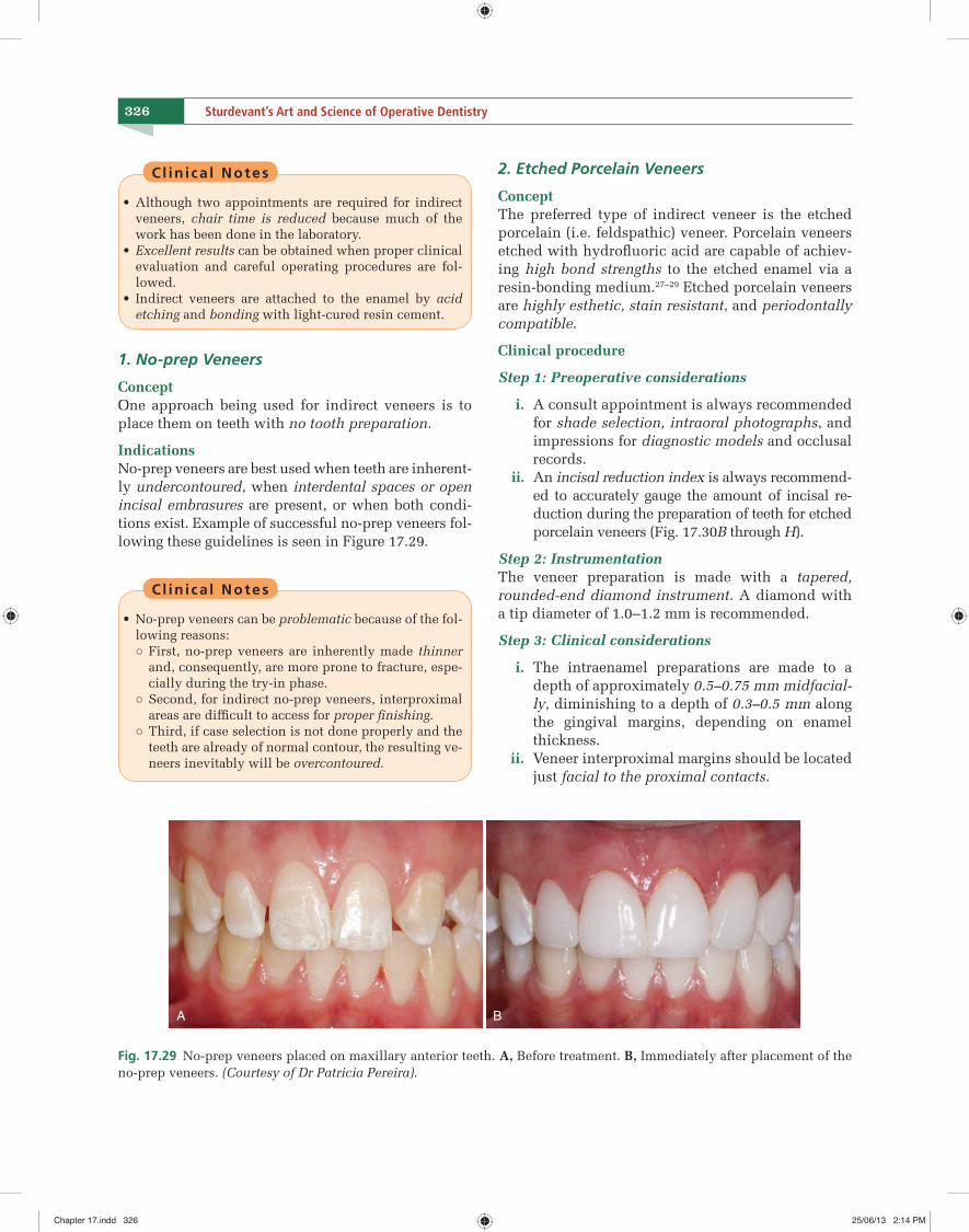
Fig. 17.29 No-prep veneers placed on maxillary anterior teeth. A, Before treatment. B, Immediately after placement of the no-prep veneers. (Courtesy of Dr Patricia Pereira).
Chapter 17.indd 326Chapter 17.indd 326 25/06/13 2:14 PM25/06/13 2:14 PM
327CHAPTER 17 Additional Conservative Esthetic Procedures
A B
C D
E F
G H
Fig. 17.30 (continued)
Chapter 17.indd 327Chapter 17.indd 327 25/06/13 2:14 PM25/06/13 2:14 PM
328 Sturdevant’s Art and Science of Operative Dentistry
I J
K L
M N
O P
Fig. 17.30 (continued)
Chapter 17.indd 328Chapter 17.indd 328 25/06/13 2:14 PM25/06/13 2:14 PM
329CHAPTER 17 Additional Conservative Esthetic Procedures
S T
U V
W X
Q R
Fig. 17.30 (continued)
Chapter 17.indd 329Chapter 17.indd 329 25/06/13 2:14 PM25/06/13 2:14 PM
C H A P T E R
19
339
Introduction to Amalgam Restorations
“To study the phenomena of disease is to sail an uncharted sea…While to study patients without books is not to go to sea at all…”.
—SIR WILLIAM OSLER, 1901
Amalgam
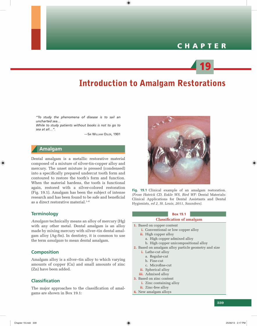
Dental amalgam is a metallic restorative material composed of a mixture of silver-tin-copper alloy and mercury. The unset mixture is pressed (condensed) into a specifi cally prepared undercut tooth form and contoured to restore the tooth’s form and function. When the material hardens, the tooth is functional again, restored with a silver-colored restoration (Fig. 19.1). Amalgam has been the subject of intense research and has been found to be safe and benefi cial as a direct restorative material.1–8
Terminology
Amalgam technically means an alloy of mercury (Hg) with any other metal. Dental amalgam is an alloy made by mixing mercury with silver–tin dental amal-gam alloy (Ag-Sn). In dentistry, it is common to use the term amalgam to mean dental amalgam.
Composition
Amalgam alloy is a silver–tin alloy to which varying amounts of copper (Cu) and small amounts of zinc (Zn) have been added.
Classifi cation
The major approaches to the classifi cation of amal-gams are shown in Box 19.1:
Fig. 19.1 Clinical example of an amalgam restoration. (From Hatrick CD, Eakle WS, Bird WF: Dental Materials: Clinical Applications for Dental Assistants and Dental Hygienists, ed 2, St. Louis, 2011, Saunders).
Box 19.1
Classifi cation of amalgam
1. Based on copper content i. Conventional or low copper alloy ii. High copper alloy
a. High copper admixed alloyb. High copper unicompositional alloy
2. Based on amalgam alloy particle geometry and size i. Lathe-cut alloy
a. Regular-cutb. Fine-cutc. Microfi ne-cut
ii. Spherical alloy iii. Admixed alloy3. Based on zinc content i. Zinc containing alloy ii. Zinc-free alloy4. New amalgam alloys
Chapter 19.indd 339Chapter 19.indd 339 25/06/13 2:17 PM25/06/13 2:17 PM
343CHAPTER 19 Introduction to Amalgam Restorations
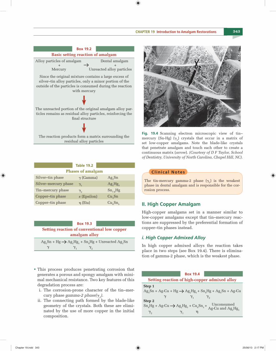
Cl in i ca l Notes
The tin-mercury gamma-2 phase (�2) is the weakest phase in dental amalgam and is responsible for the cor-rosion process.
II. High Copper Amalgam
High-copper amalgams set in a manner similar to low-copper amalgams except that tin–mercury reac-tions are suppressed by the preferential formation of copper–tin phases instead.
i. High Copper Admixed Alloy
In high copper admixed alloys the reaction takes place in two steps (see Box 19.4). There is elimina-tion of gamma-2 phase, which is the weakest phase.
Box 19.2
Basic setting reaction of amalgam
Alloy particles of amalgam Dental amalgam + + Mercury Unreacted alloy particles
Since the original mixture contains a large excess of silver–tin alloy particles, only a minor portion of the
outside of the particles is consumed during the reaction with mercury
The unreacted portion of the original amalgam alloy par-ticles remains as residual alloy particles, reinforcing the
fi nal structure
The reaction products form a matrix surrounding the residual alloy particles
Table 19.2
Phases of amalgamSilver–tin phase � (Gamma) Ag3Sn
Silver–mercury phase �1Ag2Hg3
Tin–mercury phase �2Sn7-8Hg
Copper–tin phase � (Epsilon) Cu3Sn
Copper–tin phase � (Eta) Cu6Sn5
Fig. 19.4 Scanning electron microscopic view of tin–mercury (Sn-Hg) (�2) crystals that occur in a matrix of set low-copper amalgams. Note the blade-like crystals that penetrate amalgam and touch each other to create a continuous matrix (arrow). (Courtesy of D F Taylor, School of Dentistry, University of North Carolina, Chapel Hill, NC).
Box 19.3
Setting reaction of conventional low copper amalgam alloy
Ag3Sn + Hg Ag2Hg3 + Sn8Hg + Unreacted Ag3Sn � �1 �2
• This process produces penetrating corrosion that generates a porous and spongy amalgam with mini-mal mechanical resistance. Two key features of this degradation process are:
i. The corrosion-prone character of the tin–mer-cury phase gamma-2 phase(g2).
ii. The connecting path formed by the blade-like geometry of the crystals. Both these are elimi-nated by the use of more copper in the initial composition.
Box 19.4
Setting reaction of high-copper admixed alloy
Step 1 Ag3Sn + Ag-Cu + Hg Ag2Hg3 + Sn8Hg + Ag3Sn + Ag-Cu
� �1 �2 Step 2Sn8Hg + Ag-Cu Ag2Hg3 + Cu6Sn5 + Unconsumed
Ag-Cu and Ag2Hg3 �2 �1 �
Chapter 19.indd 343Chapter 19.indd 343 25/06/13 2:17 PM25/06/13 2:17 PM
C H A P T E R
20
361
Class I and II Amalgam Restorations
“Endurance is not just the ability to bear a hard thing, but to turn it into glory”.
—WILLIAM BARCLAY
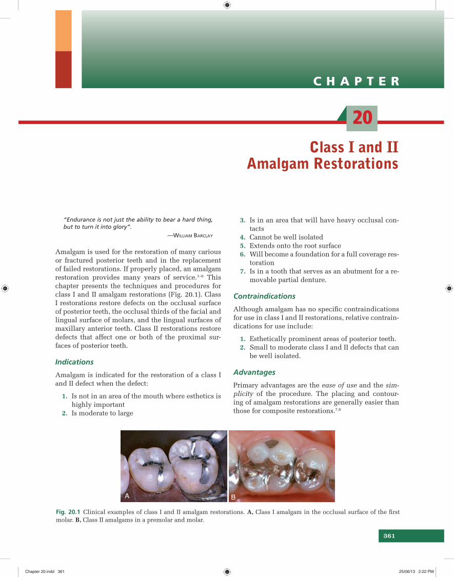
Amalgam is used for the restoration of many carious or fractured posterior teeth and in the replacement of failed restorations. If properly placed, an amalgam restoration provides many years of service.1–6 This chapter presents the techniques and procedures for class I and II amalgam restorations (Fig. 20.1). Class I restorations restore defects on the occlusal surface of posterior teeth, the occlusal thirds of the facial and lingual surface of molars, and the lingual surfaces of maxillary anterior teeth. Class II restorations restore defects that affect one or both of the proximal sur-faces of posterior teeth.
Indications
Amalgam is indicated for the restoration of a class I and II defect when the defect:
1. Is not in an area of the mouth where esthetics is highly important
2. Is moderate to large
3. Is in an area that will have heavy occlusal con-tacts
4. Cannot be well isolated 5. Extends onto the root surface 6. Will become a foundation for a full coverage res-
toration 7. Is in a tooth that serves as an abutment for a re-
movable partial denture.
Contraindications
Although amalgam has no specifi c contraindications for use in class I and II restorations, relative contrain-dications for use include:
1. Esthetically prominent areas of posterior teeth. 2. Small to moderate class I and II defects that can
be well isolated.
Advantages
Primary advantages are the ease of use and the sim-plicity of the procedure. The placing and contour-ing of amalgam restorations are generally easier than those for composite restorations.7,8
BA
Fig. 20.1 Clinical examples of class I and II amalgam restorations. A, Class I amalgam in the occlusal surface of the fi rst molar. B, Class II amalgams in a premolar and molar.
Chapter 20.indd 361Chapter 20.indd 361 25/06/13 2:22 PM25/06/13 2:22 PM

366 Sturdevant’s Art and Science of Operative Dentistry
Step 3: Extension towards central fi ssure • The bur’s orientation and depth are maintained while extending along the central fi ssure toward the mesial pit, following the DEJ (see Fig. 20.4E). • When the central fi ssure has minimal caries, one pass through the fi ssure at the prescribed depth provides the desired minimal width to the isthmus. Ideally, the width of the isthmus should be just wider than the diameter of the bur.
Cl in i ca l Notes
It is well established that a tooth preparation with a nar-row occlusal isthmus is less prone to fracture.19,20
Step 4: Extension towards opposing marginal ridge (if required) • If the fi ssure extends farther onto the marginal ridge, the long axis of the bur should be changed to establish a slight occlusal divergence to the mesial wall if the marginal ridge would be otherwise un-dermined of its dentinal support. • Figure 20.5 illustrates the correct and incorrect preparation of the mesial and distal walls.
Step 5: Facial and lingual wall extension (if required)The remainder of any occlusal enamel defects is in-cluded in the outline, and the facial and lingual walls
are extended, if necessary, to remove enamel under-mined by caries.21
Cl in i ca l Notes
The strongest and ideal enamel margin should be com-posed of full-length enamel rods attached to sound den-tin, supported on the preparation side by shorter rods, also attached to sound dentin (Fig. 20.6).
Step 6: Enameloplasty (if required)When the remaining fi ssure is no deeper than one-quarter to one-third the thickness of enamel, enam-
A B C
Correct
No. 245 bur
1.6mm
IncorrectCorrect�1.6mm
Contactarea
b a
Fig. 20.5 The direction of the mesial and distal walls is infl uenced by the remaining thickness of the marginal ridge as measured from the mesial or distal margin (a) to the proximal surface (i.e. imaginary projection of proximal surface) (b). A, Mesial and distal walls should converge occlusally when the distance from a to b is greater than 1.6mm. B, When the operator judges that the extension will leave only 1.6mm thickness (two diameters of No. 245 bur) of marginal ridge (i.e. premolars) as illustrated here and in Fig.20.4B and C, the mesial and distal walls must diverge occlusally to conserve ridge-supporting dentin. C, Extending the mesial or distal walls to a two-diameter limit without diverging the wall occlusally undermines the marginal ridge enamel.
A B
Enamel
Dentin
a
b
Fig. 20.6 A and B, The ideal and strongest enamel margin is formed by full-length enamel rods (a) resting on sound dentin supported on the preparation side by shorter rods, also resting on sound dentin (b).
Chapter 20.indd 366Chapter 20.indd 366 25/06/13 2:22 PM25/06/13 2:22 PM
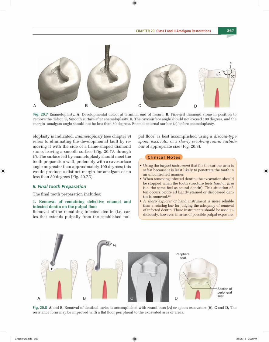
367CHAPTER 20 Class I and II Amalgam Restorations
eloplasty is indicated. Enameloplasty (see chapter 9) refers to eliminating the developmental fault by re-moving it with the side of a fl ame-shaped diamond stone, leaving a smooth surface (Fig. 20.7A through C). The surface left by enameloplasty should meet the tooth preparation wall, preferably with a cavosurface angle no greater than approximately 100 degrees; this would produce a distinct margin for amalgam of no less than 80 degrees (Fig. 20.7D).
II. Final tooth Preparation
The fi nal tooth preparation includes:
1. Removal of remaining defective enamel and infected dentin on the pulpal fl oorRemoval of the remaining infected dentin (i.e. car-ies that extends pulpally from the established pul-
pal fl oor) is best accomplished using a discoid-type spoon excavator or a slowly revolving round carbide bur of appropriate size (Fig. 20.8).
Cl in i ca l Notes
• Using the largest instrument that fi ts the carious area is safest because it is least likely to penetrate the tooth in an uncontrolled manner.
• When removing infected dentin, the excavation should be stopped when the tooth structure feels hard or fi rm (i.e. the same feel as sound dentin). This situation of-ten occurs before all lightly stained or discolored den-tin is removed.22
• A sharp explorer or hand instrument is more reliable than a rotating bur for judging the adequacy of removal of infected dentin. These instruments should be used ju-diciously, however, in areas of possible pulpal exposure.
A D
80° 100°
e
B C
Fig. 20.7 Enameloplasty. A, Developmental defect at terminal end of fi ssure. B, Fine-grit diamond stone in position to remove the defect. C, Smooth surface after enameloplasty. D, The cavosurface angle should not exceed 100 degrees, and the margin–amalgam angle should not be less than 80 degrees. Enamel external surface (e) before enameloplasty.
A B C D
13-7-14
Peripheralseat
Section ofperipheralseat
Fig. 20.8 A and B, Removal of dentinal caries is accomplished with round burs (A) or spoon excavators (B). C and D, The resistance form may be improved with a fl at fl oor peripheral to the excavated area or areas.
Chapter 20.indd 367Chapter 20.indd 367 25/06/13 2:22 PM25/06/13 2:22 PM
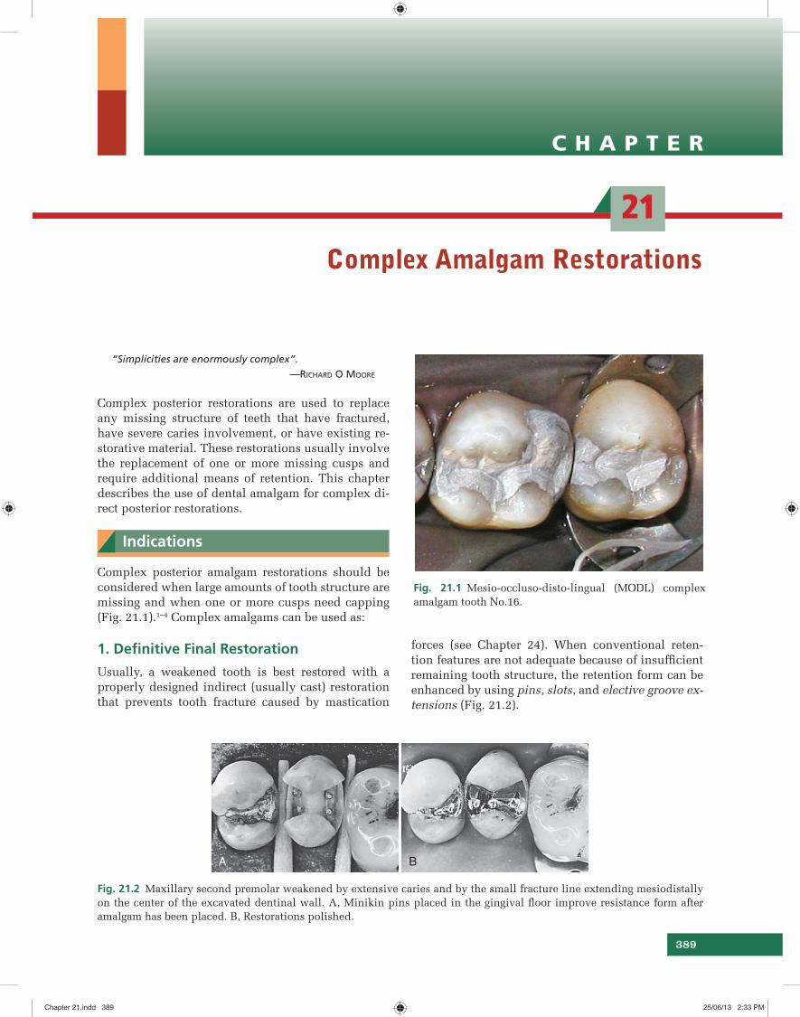
C H A P T E R
21
389
Complex Amalgam Restorations
“Simplicities are enormously complex”.—RICHARD O MOORE
Complex posterior restorations are used to replace any missing structure of teeth that have fractured, have severe caries involvement, or have existing re-storative material. These restorations usually involve the replacement of one or more missing cusps and require additional means of retention. This chapter describes the use of dental amalgam for complex di-rect posterior restorations.
Indications
Complex posterior amalgam restorations should be considered when large amounts of tooth structure are missing and when one or more cusps need capping (Fig. 21.1).1–4 Complex amalgams can be used as:
1. Defi nitive Final Restoration
Usually, a weakened tooth is best restored with a properly designed indirect (usually cast) restoration that prevents tooth fracture caused by mastication
forces (see Chapter 24). When conventional reten-tion features are not adequate because of insuffi cient remaining tooth structure, the retention form can be enhanced by using pins, slots, and elective groove ex-tensions (Fig. 21.2).
Fig. 21.1 Mesio-occluso-disto-lingual (MODL) complex amalgam tooth No.16.
A B
Fig. 21.2 Maxillary second premolar weakened by extensive caries and by the small fracture line extending mesiodistally on the center of the excavated dentinal wall. A, Minikin pins placed in the gingival fl oor improve resistance form after amalgam has been placed. B, Restorations polished.
Chapter 21.indd 389Chapter 21.indd 389 25/06/13 2:33 PM25/06/13 2:33 PM
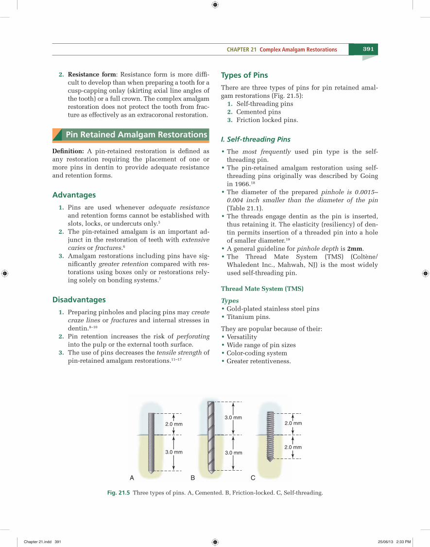
391CHAPTER 21 Complex Amalgam Restorations
2. Resistance form: Resistance form is more diffi -cult to develop than when preparing a tooth for a cusp-capping onlay (skirting axial line angles of the tooth) or a full crown. The complex amalgam restoration does not protect the tooth from frac-ture as effectively as an extracoronal restoration.
Pin Retained Amalgam Restorations
Defi nition: A pin-retained restoration is defi ned as any restoration requiring the placement of one or more pins in dentin to provide adequate resistance and retention forms.
Advantages
1. Pins are used whenever adequate resistance and retention forms cannot be established with slots, locks, or undercuts only.5
2. The pin-retained amalgam is an important ad-junct in the restoration of teeth with extensive caries or fractures.6
3. Amalgam restorations including pins have sig-nifi cantly greater retention compared with res-torations using boxes only or restorations rely-ing solely on bonding systems.7
Disadvantages
1. Preparing pinholes and placing pins may create craze lines or fractures and internal stresses in dentin.8–10
2. Pin retention increases the risk of perforating into the pulp or the external tooth surface.
3. The use of pins decreases the tensile strength of pin-retained amalgam restorations.11–17
Types of Pins
There are three types of pins for pin retained amal-gam restorations (Fig. 21.5): 1. Self-threading pins 2. Cemented pins 3. Friction locked pins.
I. Self-threading Pins
• The most frequently used pin type is the self-threading pin. • The pin-retained amalgam restoration using self-threading pins originally was described by Going in 1966.18 • The diameter of the prepared pinhole is 0.0015–0.004 inch smaller than the diameter of the pin (Table 21.1). • The threads engage dentin as the pin is inserted, thus retaining it. The elasticity (resiliency) of den-tin permits insertion of a threaded pin into a hole of smaller diameter.19
• A general guideline for pinhole depth is 2mm. • The Thread Mate System (TMS) (Coltène/Whaledent Inc., Mahwah, NJ) is the most widely used self-threading pin.
Thread Mate System (TMS)
Types • Gold-plated stainless steel pins • Titanium pins.
They are popular because of their: • Versatility • Wide range of pin sizes • Color-coding system • Greater retentiveness.
A B C
2.0 mm
3.0 mm
2.0 mm
2.0 mm
3.0 mm
3.0 mm
Fig. 21.5 Three types of pins. A, Cemented. B, Friction-locked. C, Self-threading.
Chapter 21.indd 391Chapter 21.indd 391 25/06/13 2:33 PM25/06/13 2:33 PM
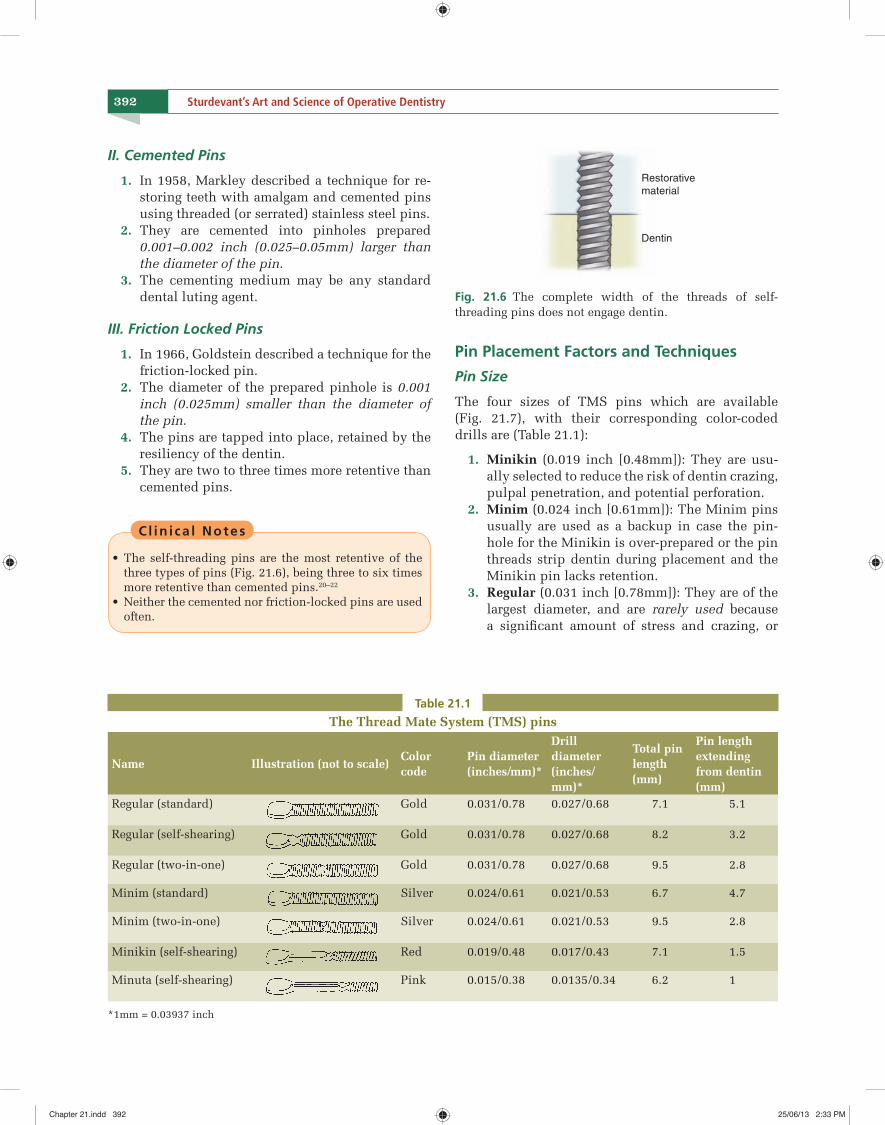
392 Sturdevant’s Art and Science of Operative Dentistry
II. Cemented Pins
1. In 1958, Markley described a technique for re-storing teeth with amalgam and cemented pins using threaded (or serrated) stainless steel pins.
2. They are cemented into pinholes prepared 0.001–0.002 inch (0.025–0.05mm) larger than the diameter of the pin.
3. The cementing medium may be any standard dental luting agent.
III. Friction Locked Pins
1. In 1966, Goldstein described a technique for the friction-locked pin.
2. The diameter of the prepared pinhole is 0.001 inch (0.025mm) smaller than the diameter of the pin.
4. The pins are tapped into place, retained by the resiliency of the dentin.
5. They are two to three times more retentive than cemented pins.
Cl in i ca l Notes
• The self-threading pins are the most retentive of the three types of pins (Fig. 21.6), being three to six times more retentive than cemented pins.20–22
• Neither the cemented nor friction-locked pins are used often.
Pin Placement Factors and Techniques
Pin Size
The four sizes of TMS pins which are available (Fig. 21.7), with their corresponding color-coded drills are (Table 21.1):
1. Minikin (0.019 inch [0.48mm]): They are usu-ally selected to reduce the risk of dentin crazing, pulpal penetration, and potential perforation.
2. Minim (0.024 inch [0.61mm]): The Minim pins usually are used as a backup in case the pin-hole for the Minikin is over-prepared or the pin threads strip dentin during placement and the Minikin pin lacks retention.
3. Regular (0.031 inch [0.78mm]): They are of the largest diameter, and are rarely used because a signifi cant amount of stress and crazing, or
Table 21.1
The Thread Mate System (TMS) pins
Name Illustration (not to scale)Color code
Pin diameter (inches/mm)*
Drill diameter (inches/mm)*
Total pin length (mm)
Pin length extending from dentin (mm)
Regular (standard) Gold 0.031/0.78 0.027/0.68 7.1 5.1
Regular (self-shearing) Gold 0.031/0.78 0.027/0.68 8.2 3.2
Regular (two-in-one) Gold 0.031/0.78 0.027/0.68 9.5 2.8
Minim (standard) Silver 0.024/0.61 0.021/0.53 6.7 4.7
Minim (two-in-one) Silver 0.024/0.61 0.021/0.53 9.5 2.8
Minikin (self-shearing) Red 0.019/0.48 0.017/0.43 7.1 1.5
Minuta (self-shearing) Pink 0.015/0.38 0.0135/0.34 6.2 1
*1mm = 0.03937 inch
Restorativematerial
Dentin
Fig. 21.6 The complete width of the threads of self-threading pins does not engage dentin.
Chapter 21.indd 392Chapter 21.indd 392 25/06/13 2:33 PM25/06/13 2:33 PM
C H A P T E R
24
429
Class II Cast Metal Restorations
“You arrive at precision…When you become precise in your technique…”.
The cast metal restoration is an indirect restoration that involves numerous steps and dental materials, with meticulous attention to detail. Typically, a den-tal laboratory is involved, and the dentist and the lab-oratory technician must be devoted to perfection. The high degree of satisfaction and service derived from a properly made cast metal restoration is a reward for the painstaking application required.1
Defi nitions
1. The class II inlay is an intracoronal cast metal restoration that involves the occlusal and proxi-mal surfaces of a posterior tooth.
2. The partial onlay is a cast metal restoration that involves the occlusal and proximal surfaces of a posterior and covers and restores at least one but not all of the cusp tips of a posterior tooth.
3. The class II onlay is a cast metal restoration that involves the occlusal and proximal surfaces of a posterior tooth and caps all of the cusps.
Cast Metal Alloys
Cast metal restorations can be made from a variety of casting alloys. Their high compressive and tensile strengths are especially valuable in restorations that rebuild most or all of the occlusal surface.
At present, four distinct groups of alloys are in use for cast restorations:
1. Traditional high-gold alloys (ADA specifi cation No. 5)
2. Low-gold alloys
3. Palladium–silver alloys 4. Base metal alloys (most commonly used).
Cl in i ca l Notes
• The American Dental Association (ADA) Specifi cation No. 5 for dental casting gold alloys requires a mini-mum total gold-plus-noble-metals content of 75 weight percent (wt%). Such traditional high-gold alloys are unreactive in the oral environment and are some of the most biocompatible materials available to the re-storative dentist.2 However, their usage has drastically reduced due to the increasing cost of gold and other noble alloys.
• Each of the alternatives to high-gold alloys have asso-ciated problems of reduced performance, most com-monly related to :
○ Decreased tarnish resistance ○ Decreased burnishability.3 ○ Higher incidences of post-restorative allergy, most often exhibited by irritated soft tissue adjacent to the restoration.
Indications
i. Large Restorations
1. When proximal surface caries is extensive, the cast metal inlay is an alternative to amalgam or composite when the higher strength of a casting alloy is needed.
2. The cast metal onlay is often an excellent alter-native to a crown for teeth that have been greatly weakened by caries or by large, failing restora-tions but where the facial and lingual tooth sur-faces are relatively unaffected by disease or in-jury.
Chapter 24.indd 429Chapter 24.indd 429 25/06/13 2:50 PM25/06/13 2:50 PM
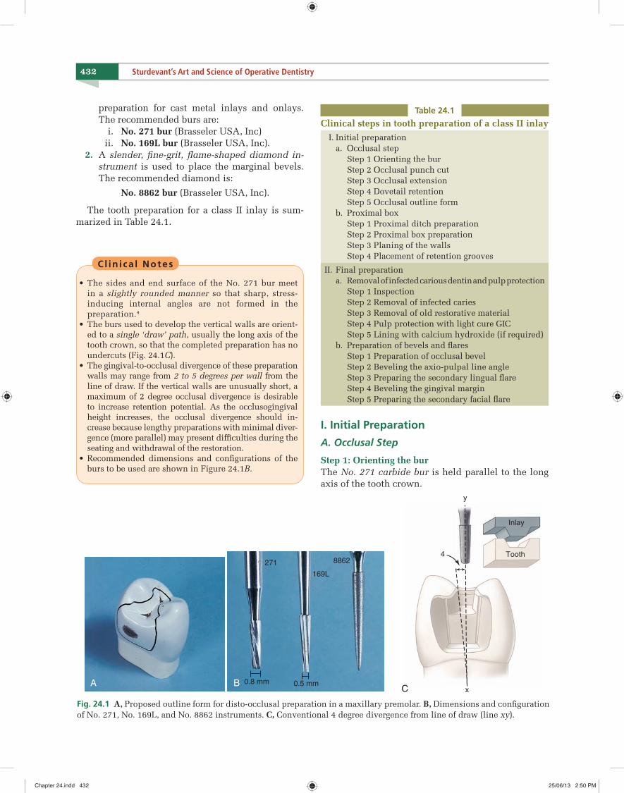
432 Sturdevant’s Art and Science of Operative Dentistry
preparation for cast metal inlays and onlays. The recommended burs are:
i. No. 271 bur (Brasseler USA, Inc) ii. No. 169L bur (Brasseler USA, Inc). 2. A slender, fi ne-grit, fl ame-shaped diamond in-
strument is used to place the marginal bevels. The recommended diamond is:
No. 8862 bur (Brasseler USA, Inc).
The tooth preparation for a class II inlay is sum-marized in Table 24.1.
Cl in i ca l Notes
• The sides and end surface of the No. 271 bur meet in a slightly rounded manner so that sharp, stress-inducing internal angles are not formed in the preparation.4
• The burs used to develop the vertical walls are orient-ed to a single ‘draw’ path, usually the long axis of the tooth crown, so that the completed preparation has no undercuts (Fig. 24.1C).
• The gingival-to-occlusal divergence of these preparation walls may range from 2 to 5 degrees per wall from the line of draw. If the vertical walls are unusually short, a maximum of 2 degree occlusal divergence is desirable to increase retention potential. As the occlusogingival height increases, the occlusal divergence should in-crease because lengthy preparations with minimal diver-gence (more parallel) may present diffi culties during the seating and withdrawal of the restoration.
• Recommended dimensions and confi gurations of the burs to be used are shown in Figure 24.1B.
C
4
x
y
Inlay
Tooth
A B 0.8 mm 0.5 mm
271
169L
8862
Fig. 24.1 A, Proposed outline form for disto-occlusal preparation in a maxillary premolar. B, Dimensions and confi guration of No. 271, No. 169L, and No. 8862 instruments. C, Conventional 4 degree divergence from line of draw (line xy).
Table 24.1
Clinical steps in tooth preparation of a class II inlay I. Initial preparation
a. Occlusal stepStep 1 Orienting the burStep 2 Occlusal punch cutStep 3 Occlusal extensionStep 4 Dovetail retentionStep 5 Occlusal outline form
b. Proximal boxStep 1 Proximal ditch preparationStep 2 Proximal box preparation Step 3 Planing of the walls Step 4 Placement of retention grooves
II. Final preparationa. Removal of infected carious dentin and pulp protection
Step 1 InspectionStep 2 Removal of infected cariesStep 3 Removal of old restorative materialStep 4 Pulp protection with light cure GICStep 5 Lining with calcium hydroxide (if required)
b. Preparation of bevels and fl aresStep 1 Preparation of occlusal bevelStep 2 Beveling the axio-pulpal line angleStep 3 Preparing the secondary lingual fl areStep 4 Beveling the gingival marginStep 5 Preparing the secondary facial fl are
I. Initial Preparation
A. Occlusal Step
Step 1: Orienting the burThe No. 271 carbide bur is held parallel to the long axis of the tooth crown.
Chapter 24.indd 432Chapter 24.indd 432 25/06/13 2:50 PM25/06/13 2:50 PM
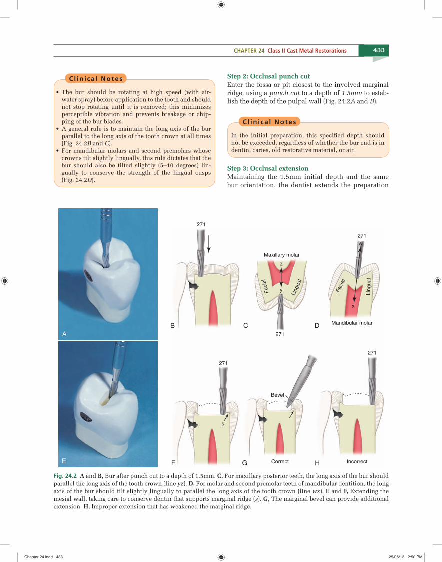
433CHAPTER 24 Class II Cast Metal Restorations
B C D
F G H
271
Maxillary molar
z
271
271
271
Facia
l
Lin
gual
y
x
271
w
Mandibular molar
Faci
al
Lin
gual
s
Bevel
Correct Incorrect
A
E
Fig. 24.2 A and B, Bur after punch cut to a depth of 1.5mm. C, For maxillary posterior teeth, the long axis of the bur should parallel the long axis of the tooth crown (line yz). D, For molar and second premolar teeth of mandibular dentition, the long axis of the bur should tilt slightly lingually to parallel the long axis of the tooth crown (line wx). E and F, Extending the mesial wall, taking care to conserve dentin that supports marginal ridge (s). G, The marginal bevel can provide additional extension. H, Improper extension that has weakened the marginal ridge.
Cl in i ca l Notes
• The bur should be rotating at high speed (with air-water spray) before application to the tooth and should not stop rotating until it is removed; this minimizes perceptible vibration and prevents breakage or chip-ping of the bur blades.
• A general rule is to maintain the long axis of the bur parallel to the long axis of the tooth crown at all times (Fig. 24.2B and C).
• For mandibular molars and second premolars whose crowns tilt slightly lingually, this rule dictates that the bur should also be tilted slightly (5–10 degrees) lin-gually to conserve the strength of the lingual cusps (Fig. 24.2D).
Step 2: Occlusal punch cutEnter the fossa or pit closest to the involved marginal ridge, using a punch cut to a depth of 1.5mm to estab-lish the depth of the pulpal wall (Fig. 24.2A and B).
Cl in i ca l Notes
In the initial preparation, this specifi ed depth should not be exceeded, regardless of whether the bur end is in dentin, caries, old restorative material, or air.
Step 3: Occlusal extensionMaintaining the 1.5mm initial depth and the same bur orientation, the dentist extends the preparation
Chapter 24.indd 433Chapter 24.indd 433 25/06/13 2:50 PM25/06/13 2:50 PM
452 Sturdevant’s Art and Science of Operative Dentistry
Restorative Techniques for Cast Metal Restoration
The restorative technique for a cast metal restoration can be divided into the following stages as shown in Table 24.4.
I. Interocclusal Record
The maximum intercuspation interocclusal record can be made from one of several commercially availa-ble bite registration pastes. The most commonly used bite registration pastes are composed of heavily fi lled polyvinyl siloxane (PVS) impression materials. Sev-eral materials are available in cartridge systems that automatically mix the base and accelerator pastes to-gether as they are expressed through a special dispos-able mixing tip (Fig. 24.18A).
Technique
1. The mixed impression material is dispensed directly onto the prepared teeth and their op-ponents, and then the patient closes the mouth completely (Fig. 24.18B, C).
2. The dentist observes teeth not covered by the bite registration paste to verify that teeth are in maximum intercuspation.
3. When the material has set, the dentist removes the interocclusal record and inspects it for complete-ness. When held up to a light, areas where the ad-jacent unprepared teeth have penetrated through the material should be seen (Fig. 24.18D).
II. Custom Temporary Restoration
Between the time the tooth is prepared and the cast metal restoration is delivered, it is important that the patient be comfortable and the tooth be protected and stabilized with an adequate temporary restoration. The custom temporary restoration should satisfy the following requirements:
1. It should be nonirritating and protect the pre-pared tooth from injury.
2. It should protect and maintain the health of the periodontium.
3. It should maintain the position of the prepared, adjacent, and opposing teeth.
4. It should provide for esthetic, phonetic, and masticatory function, as indicated.
5. It should have adequate strength and retention to withstand the forces to which it will be sub-jected.
Temporaries can be fabricated by two methods:
1. Direct technique: Intraorally directly on the pre-pared teeth.
2. Indirect technique: Extraorally outside of the mouth using a postoperative cast of the pre-pared teeth.
Cl in i ca l Notes
The indirect technique is not as popular as the direct technique because of the increased number of steps and complexity in the former.
Technique for Direct Temporary Restoration
The direct temporary technique involves forming the temporary restoration directly on the prepared tooth (Fig. 24.19).
Advantages 1. The direct technique involves fewer steps and
materials because no postoperative impression and gypsum cast are required.
2. It is much faster than the indirect technique.
TABLE 24.4
Stages of laboratory fabrication of a cast metal restoration
I. Interocclusal record
II. Custom temporary restoration
III. Final impression i. Tissue retraction ii. Polyvinyl siloxane (PVS) impression
a. Tray selectionb. Impression technique
IV. Working cast and dies
V. Wax pattern
VI. Spruing, investing casting, fi nishing, seating, adjusting and polishing the casting
VII. Trying in the casting i. Preparing the mouth ii. Seating the casting and adjusting proximal
contacts iii. Occluding the casting iv. Improving marginal adaptation
VIII. Cementation
Chapter 24.indd 452Chapter 24.indd 452 25/06/13 2:50 PM25/06/13 2:50 PM
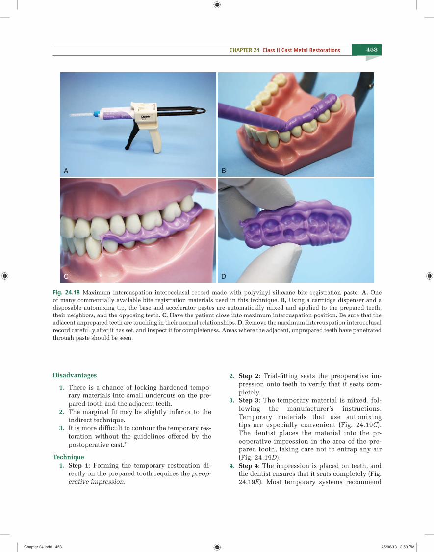
453CHAPTER 24 Class II Cast Metal Restorations
Disadvantages
1. There is a chance of locking hardened tempo-rary materials into small undercuts on the pre-pared tooth and the adjacent teeth.
2. The marginal fi t may be slightly inferior to the indirect technique.
3. It is more diffi cult to contour the temporary res-toration without the guidelines offered by the postoperative cast.7
Technique 1. Step 1: Forming the temporary restoration di-
rectly on the prepared tooth requires the preop-erative impression.
2. Step 2: Trial-fi tting seats the preoperative im-pression onto teeth to verify that it seats com-pletely.
3. Step 3: The temporary material is mixed, fol-lowing the manufacturer’s instructions. Temporary materials that use automixing tips are especially convenient (Fig. 24.19C). The dentist places the material into the pr-eoperative impression in the area of the pre-pared tooth, taking care not to entrap any air (Fig. 24.19D).
4. Step 4: The impression is placed on teeth, and the dentist ensures that it seats completely (Fig. 24.19E). Most temporary systems recommend
A B
C D
Fig. 24.18 Maximum intercuspation interocclusal record made with polyvinyl siloxane bite registration paste. A, One of many commercially available bite registration materials used in this technique. B, Using a cartridge dispenser and a disposable automixing tip, the base and accelerator pastes are automatically mixed and applied to the prepared teeth, their neighbors, and the opposing teeth. C, Have the patient close into maximum intercuspation position. Be sure that the adjacent unprepared teeth are touching in their normal relationships. D, Remove the maximum intercuspation interocclusal record carefully after it has set, and inspect it for completeness. Areas where the adjacent, unprepared teeth have penetrated through paste should be seen.
Chapter 24.indd 453Chapter 24.indd 453 25/06/13 2:50 PM25/06/13 2:50 PM