
Study on carbon dioxide thermodynamic behavior for the ...
8
BULLETIN OF THE POLISH ACADEMY OF SCIENCES TECHNICAL SCIENCES, Vol. 61, No. 3, 2013 DOI: 10.2478/bpasts-2013-0063 Study on carbon dioxide thermodynamic behavior for the purpose of shale rock fracturing T. NIEZGODA, D. MIEDZIŃSKA * , E. MAŁEK, P. KĘDZIERSKI, and G. SŁAWIŃSKI Department of Mechanics and Applied Computer Science, Military University of Technology, 2 S. Kaliskiego St., 00-908 Warsaw, Poland Abstract. The possibility of using CO2 to fracturing a shale rock has been presented in the paper. The described innovative method which allows for the efficient extraction of shale gas and carbon dioxide storage in a shale rock was developed in Department of Mechanics and Applied Computer Science at the Military University of Technology, Warsaw, Poland. Firstly, the method was verified on the base of analytical and experimental research. In the next stage of the method verification carbon dioxide thermodynamic behavior was studied. The growth in pressure of drop of CO2 heated in a closed volume was numerically tested. The research confirmed the efficiency of the use of carbon dioxide as a medium for fracturing of rocks. The usage of liquid CO2 can be alternative for hydraulic fracturing and is safe for the environment. Key words: carbon dioxide, shale gas, storage system, thermodynamics, FEM. 1. Introduction According to the most general selection criteria of natural gas, it can be distinguished as a constituent of conventional and unconventional deposits. Exploitation of the first kind of de- posits does not cause problems, and a recovery process has been known since 19th century. The situation is different in the case of beds in which gas is dispersed in small pores in the rock [1]. Unconventional gas is more difficult and that makes it less economical to operate. In Poland the so called shale gas is the best known, but also other unconventional deposits types can be distinguished. Besides shale gas tight gas, coal bed methane, deep gas and gas hydrates are also present (Fig. 1). They are mainly differentiated because of a place of extraction (shale rocks, isolated pores of rock, coal deposits) [1]. Fig. 1. Types of natural gas deposits after Ref. 1 Natural gas was created over million years from the rot- ting organic matter – different kinds of plants, plankton and animals covered with a thick layer of organic sediments. After a long heating with the Earth’s internal heat, heavy and light fractions of petroleum and natural gas started to precipitate from the compost. Gas was migrating to the surface until it met a trap in the form of porous rocks, also isolated from the top by impermeable rocks [1, 2]. These traps can be assumed as large tanks, from which conventional gas can be recovered with no major problems through the vertical wells. Shale gas is located in rocks, in which it was originally developed. Having a small permeability, the rocks preserved gas inside not letting him to raise the upper layers of the soil (Fig. 2). Fig. 2. Natural gas deposits Ref. 1 Similar to a conventional hydrocarbon system, unconven- tional gas reservoirs are characterized by complex geological and petrophysical systems as well as heterogeneities – at all scales. However, unconventional gas reservoirs typically have * e-mail: [email protected] 605 Unauthenticated | 89.73.89.243 Download Date | 12/9/13 3:20 PM
Transcript of Study on carbon dioxide thermodynamic behavior for the ...

BULLETIN OF THE POLISH ACADEMY OF SCIENCESTECHNICAL SCIENCES, Vol. 61, No. 3, 2013DOI: 10.2478/bpasts-2013-0063
Study on carbon dioxide thermodynamic behavior
for the purpose of shale rock fracturing
T. NIEZGODA, D. MIEDZIŃSKA∗ , E. MAŁEK, P. KĘDZIERSKI, and G. SŁAWIŃSKI
Department of Mechanics and Applied Computer Science, Military University of Technology, 2 S. Kaliskiego St., 00-908 Warsaw, Poland
Abstract. The possibility of using CO2 to fracturing a shale rock has been presented in the paper. The described innovative method whichallows for the efficient extraction of shale gas and carbon dioxide storage in a shale rock was developed in Department of Mechanicsand Applied Computer Science at the Military University of Technology, Warsaw, Poland. Firstly, the method was verified on the base ofanalytical and experimental research. In the next stage of the method verification carbon dioxide thermodynamic behavior was studied. Thegrowth in pressure of drop of CO2 heated in a closed volume was numerically tested. The research confirmed the efficiency of the use ofcarbon dioxide as a medium for fracturing of rocks. The usage of liquid CO2 can be alternative for hydraulic fracturing and is safe for theenvironment.
Key words: carbon dioxide, shale gas, storage system, thermodynamics, FEM.
1. Introduction
According to the most general selection criteria of natural gas,it can be distinguished as a constituent of conventional andunconventional deposits. Exploitation of the first kind of de-posits does not cause problems, and a recovery process hasbeen known since 19th century. The situation is different inthe case of beds in which gas is dispersed in small pores inthe rock [1].
Unconventional gas is more difficult and that makes it lesseconomical to operate. In Poland the so called shale gas isthe best known, but also other unconventional deposits typescan be distinguished. Besides shale gas tight gas, coal bedmethane, deep gas and gas hydrates are also present (Fig. 1).They are mainly differentiated because of a place of extraction(shale rocks, isolated pores of rock, coal deposits) [1].
Fig. 1. Types of natural gas deposits after Ref. 1
Natural gas was created over million years from the rot-ting organic matter – different kinds of plants, plankton andanimals covered with a thick layer of organic sediments. After
a long heating with the Earth’s internal heat, heavy and lightfractions of petroleum and natural gas started to precipitatefrom the compost. Gas was migrating to the surface until itmet a trap in the form of porous rocks, also isolated from thetop by impermeable rocks [1, 2]. These traps can be assumedas large tanks, from which conventional gas can be recoveredwith no major problems through the vertical wells.
Shale gas is located in rocks, in which it was originallydeveloped. Having a small permeability, the rocks preservedgas inside not letting him to raise the upper layers of the soil(Fig. 2).
Fig. 2. Natural gas deposits Ref. 1
Similar to a conventional hydrocarbon system, unconven-tional gas reservoirs are characterized by complex geologicaland petrophysical systems as well as heterogeneities – at allscales. However, unconventional gas reservoirs typically have
∗e-mail: [email protected]
605
Unauthenticated | 89.73.89.243Download Date | 12/9/13 3:20 PM

T. Niezgoda, D. Miedzińska, E. Małek, P. Kędzierski, and G. Sławiński
a very fine grain rock texture, exhibit gas storage and flowcharacteristics which are uniquely tied to the nano-scale porethroat and pore size distribution and possess the common or-ganic and clay content that serve as gas sorption sites. Thegas-shale reservoir pore structures are defined in terms ofnanometers to micrometers, whereas most tight gas reservoirsare described at a micrometer or larger scale. Both gas shaleand tight gas systems have free gas stored within the poresof the rock matrix. Gas-shale differs in possessing the char-acteristic of gas adsorption on surface areas associated withan organic content and clay [3].
Bustin et al. [4] states that the relative importance of ad-sorbed versus free gas varies as a function of the amount oforganic matter present, pore size distribution, mineralogy, di-genesis, rock texture and reservoir pressure and temperature.
The study on the carbon dioxide thermodynamic behav-iour carried out with the use of the finite element method ispresented in the paper. The aim of the research is to check ifthe subcritical CO2 drop injected on the hot rock surface canexplode.
2. Research background
The first attempts to exploit shales was taken in 1821, butdue to the low yield of this type of production, they weresoon stopped.The change was brought by the development ofdrilling technology and the usage of vertical drillings insteadof horizontal ones coupled with the cracks network methodsdevelopment. Commonly used method of fracturing is a hy-draulic fracturing. This method consists of injecting into theborehole a large amount water with the granules (sand) andchemicals admixture at a pressure of about 60MPa to crack
rocks and to release the gas trapped. The admixture of sand isto prevent closing slots after the pressure reduction. The de-scribed fracturing method causes many objections. Firstly, itcan cause groundwater contamination by chemical substancesused in the fracturing process. Secondly, the procedure needsto use a large amounts of water. Consumption and contami-nation of such significant quantities of water may arise objec-tions. A part of water volume returns to the surface, however,it is additionally contaminated with heavy metals and requiresutilization. The described disadvantages of the method causedseeking for another fracturing medium, such as an inert gaseasily condensable and widely available in the environment.One of such gases is CO2. A process of injection of CO2
cannot only enable rocks fracturing, but also its geologicalstorage. The last argument is particularly important in thecontext of CO2 emission limits introduced by the EuropeanUnion, which are associated with severe financial penalties.These are the arguments for considering CO2 as a medium inrock fracturing [5].
Shale is characterized by its dual porosity: it contains bothprimary (micro pores and meso pores) and secondary (macropores and natural fractures) porosity systems. The primaryporosity system contains the vast majority of the gas-in-place,while the secondary porosity system provides the conduit formass transfer to the wellbore. Primary porosity gas storage isdominated by adsorption. Primary porosity is relatively im-permeable due to its small pore size. Mass transfer for eachgas molecular species is dominated by diffusion that is drivenby the concentration gradient. A flow through the secondaryporosity system is dominated by the Darcy flow that relatesa flow rate to the permeability and pressure gradient – seeFig. 3 [3].
Fig. 3. Flow types and behaviour in shale reservoirs Ref. 3
606 Bull. Pol. Ac.: Tech. 61(3) 2013
Unauthenticated | 89.73.89.243Download Date | 12/9/13 3:20 PM
Study on carbon dioxide thermodynamic behavior for the purpose of shale rock fracturing
When the pressure of a natural fracture system in shaledrops below the critical desorption pressure, methane starts todesorb from the primary porosity and is released into the sec-ondary porosity system near the natural fractures, and then isreduced. This reduction creates a concentration gradient thatresults in mass transfer by diffusion through the micro andmeso porosity. The adsorbed gas continues to be released asthe pressure is reduced [3].
On the base of those mechanisms the analyses of the newinnovative method of gas shale fracturing and gas recoverycoupled with carbon dioxide storage have been developed inthe Department of Mechanics and Applied Computer Scienceof the Military University of Technology.
The presented method of gas shale fracturing and gas re-covery coupled with carbon dioxide storage was submitted byMilitary University as the patent no P.398228.
The method of the shale gas recovery coupled with CO2
sequestration from the horizontal small-diameter wellboresmade in a single vertical wellbore has been the subject ofthe proposed innovation.
The steps of the proposed method are presented below:
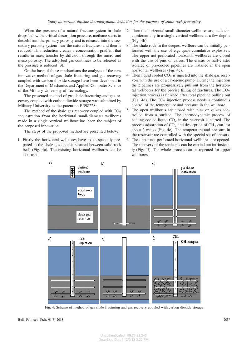
1. Firstly the horizontal wellbores have to be specially pre-pared in the shale gas deposit situated between solid rockbeds (Fig. 4a). The existing horizontal wellbores can bealso used.
2. Then the horizontal small-diameter wellbores are made cir-cumferentially in a single vertical wellbore at a few depths(Fig. 4b).
3. The shale rock in the deepest wellbore can be initially per-forated with the use of e.g. quasi-cumulative explosives.The upper not perforated horizontal wellbores are closedwith the use of pins or valves. The elastic or half-elasticisolated or pre-cooled pipelines are installed in the openhorizontal wellbores (Fig. 4c).
4. Then liquid cooled CO2 is injected into the shale gas reser-voir with the use of a cryogenic pump. During the injectionthe pipelines are progressively pull out from the horizon-tal wellbores for the precise filling of fractures. The CO2
injection process is finished after total pipeline pulling out(Fig. 4d). The CO2 injection process needs a continuouscontrol of the temperature and pressure in the wellbore.
5. The open wellbores are closed with pins or valves con-trolled from a surface. The thermodynamic process ofheating cooled liquid CO2 in the reservoir is started. Theprocess adsorption of CO2 and desorption of CH4 can lastabout 2 weeks (Fig. 4e). The temperature and pressure inthe reservoir are controlled with the special set of sensors.
6. The upper not perforated horizontal wellbores are opened.The recovery of the shale gas can be carried out intrinsical-ly (Fig. 4f). The whole process can be repeated for upperwellbores.
Fig. 4. Scheme of method of gas shale fracturing and gas recovery coupled with carbon dioxide storage
Bull. Pol. Ac.: Tech. 61(3) 2013 607
Unauthenticated | 89.73.89.243Download Date | 12/9/13 3:20 PM

T. Niezgoda, D. Miedzińska, E. Małek, P. Kędzierski, and G. Sławiński
3. Experimental and analytical verification
of the method
The method was verified on the base of analytical and exper-imental research. Assessment of the possibility of using CO2
to gas fracturing performed on the base of CO2 thermody-namic behavior chart (Fig. 5).
Fig. 5. CO2 thermodynamic behavior chart
The value of a shale gas tensile strength can be found inthe literature [6]. It varies between 3 and 18 MPa (dependingon the shale deposit location) under the standard pressure. So,if the pressure of CO2 after heating in the deposit reaches thatvalue, the method will be assumed to be correct.
The analytical calculations for thermodynamic behavior ofisochoric heating of CO2 from the temperature value of −40
(2 MPa) to 120C (a temperature in the shale reservoir) andfrom 20C (7 MPa) to 120C.
The calculations were carried out with the use of REF-PROP (Reference Properties) computer code developed by theNational Institute of Science and Technology (NIST). Thecode calculates the thermodynamic and transport propertiesof industry fluids and their mixtures with special considera-tion of cooling agents and hydrocarbons.
The Span-Wagner equation of state was applied for theCO2 thermodynamic behavior description. The equation isan empirical representation of the fundamental equation ofHelmholtz energy. Usually the dimensionless function ofHelmholtz energy φ = a/(RT ) dividend of an ideal gas partφ0 and residual part φr [7] is used:
ϕ(τ, δ) = ϕ0(τ, δ) + ϕτ (τ, δ), (1)
where τ– inverse of reduced temperature τ = Tc/T , δ – re-duced density δ = ρ/ρc, Tcand ρc – temperature and densityat critical point.
The calculations were performed for two states of liquidCO2: (−40|circC, 2 MPa) and (20C, 7 MPa). The analyticalcalculations results were presented in Fig. 6. On the base ofthose results it can be concluded that the final value of heat-ed CO2 exceeded the value of the shale rock tensile strength(212 MPa for the starting point −40C, 2 MPa and 58 MPafor the starting point 20C, 7 MPa) and can cause its damage.In both cases the minimum pressure required for the crackingof the rock was achieved.
Fig. 6. Isochoric process of heated CO2
608 Bull. Pol. Ac.: Tech. 61(3) 2013
Unauthenticated | 89.73.89.243Download Date | 12/9/13 3:20 PM

Study on carbon dioxide thermodynamic behavior for the purpose of shale rock fracturing
Fig. 7. Research equipment for CO2 thermodynamic behavior testing
Fig. 8. Comparison of analytical and experimental tests of CO2 heating
For the purpose of an analytical tests verification the ex-perimental test of the isochoric CO2 heating process was car-ried out. The CO2 was used in the form of a solid dry ice. Itwas heated in the closed pressure tank from the temperatureof 23C to 97C. The temperature was measured with the useof a cable sensor and pressure was measured with the use ofan extensometric sensor. The research equipment is presentedin Fig. 7.
The comparison of both analytical and experimental testsis shown in Fig. 8. The results showed good compatibility thatproved the correctness of an analytical method.
4. Numerical study of drop of CO2 heated
in a closed volume growth pressure
The next stage of the analysis of carbon dioxide thermody-namic behavior was to study a growth in pressure of a dropof CO2 heated in a closed volume.
An analysis was performed with the use of coupled LS-Dyna and REFPROP computer codes. With the use of LS-Dyna the CO2 temperature vs. time changes were calculatedand with the use of REFPROP the nonlinear thermal prop-erties (thermal conductivity and heat capacity) as a functionof temperature as well as changes of pressure vs. time on thebasis of temperature changes vs. time were calculated.
It was assumed that the drop of carbon dioxide is lockedin the closed heating capsule and in the initial phase of ananalysis the pressure in the capsule provides a CO2 liquidstate.
In accordance to the symmetry of the researched phenom-enon 1/8 model was built (Fig. 9). Dimensions of the modelwere as follows: 0.75 mm × 0.75 mm × 0.75 mm when theradius of the drop of carbon dioxide was 0.5 mm. On the ex-ternal surface of a model adiabatic conditions were assumed.The initial temperature of the drop of carbon dioxide was
Bull. Pol. Ac.: Tech. 61(3) 2013 609
Unauthenticated | 89.73.89.243Download Date | 12/9/13 3:20 PM

T. Niezgoda, D. Miedzińska, E. Małek, P. Kędzierski, and G. Sławiński
253K at the density of 1032 kg/m3. However, the temperatureof the capsule, which was used to heat the CO2 was 373 Kand was constant. The analysis was of the nonlinear, thermaltype.
Fig. 9. FE model geometry
The model was developed with the use of 11000 hex finiteelements. The description of finite elements is as follows:
• hex elements,• fully integrated elements,• every element has eight nodes or 8 points of integration,• every node has three degrees of freedom [8].
The thermal isotropic material model was used for sim-ulating CO2 (T01) and shale rock (T02). Physical propertiesof the materials used to build the model are presented in Ta-ble 1 [9].
Table 1Physical properties of materials Ref. 9
MaterialDensity[kg/m3]
Heatcapacity[J/kgK]
Thermalconductivity
[W/mK]
Shale rock 1500 1200 0.26
Carbon dioxide 1032 See Fig. 10 See Fig. 11
Conduction of heat in an orthotropic solid in LS-Dyna iscalculated as follows:
• the differential equations of conduction of heat in a three-dimensional continuum is given by
ρ cp
∂θ
∂t= (kij θ,j),i + Q, (2)
• subject to the boundary conditions
θ = θs on Γ1,
kij θ,j ni +βθ = γ on Γ2
(3)
• and initial conditions at t0:
θΓ = θ0(xi) at t = t0 (4)
whereθ = θ(xi, t) – temperature,xi = xi(t) – coordinates as a function of time,ρ = ρ(xi) – density,cp = cp(xi, θ) – specific heat,kij = kij(xi, θ) – thermal conductivity,Q = Q(xi, θ) – internal heat generation rate per unit vol-ume Ω,θΓ – prescribed temperature on Γ1,ni – normal vector Γ2.
Equations (2)–(4) represent the strong form of a boundaryvalue problem to be solved for the temperature field withinthe solid [8].
Fig. 10. Heat capacity vs. temperature chart
610 Bull. Pol. Ac.: Tech. 61(3) 2013
Unauthenticated | 89.73.89.243Download Date | 12/9/13 3:20 PM

Study on carbon dioxide thermodynamic behavior for the purpose of shale rock fracturing
Fig. 11. Thermal conductivity vs. temperature chart
a)
b)
Fig. 12. Drop of CO2 heating: a) pressure vs. time chart b) temper-ature vs. time chart
On the basis of nonlinear thermal analysis curves(Figs. 10–11) were determined, which represent thermal prop-erties of liquid carbon dioxide that was transformed isochor-ically (volume = constants) from the temperature of 253 Kto 373 K. They were calculated in REFPROP computer code.In this case the program uses a thermal conductivity of theVesovic pure liquid model and the Span-Wagner equation of
state [7]. The calculation results were implemented in LS-Dyna for modeling CO2 thermal behavior.
The changes in pressure and temperature versus timeachieved with the use of LS Dyna code are shown in Figs. 12a)and b), respectively.
The results presented in the charts Fig. 12a) and b) showthat both pressure and temperature of carbon dioxide increas-es with time. The increase in pressure and temperature is notrapid. The achievement of maximum pressure after the peri-od of 0.9 s allows to conclude that the transformation is notexplosive.
5. Conclusions
The paper describes the innovative method which allows forthe efficient extraction of shale gas and a carbon dioxide stor-age shale rock. The method was verified on the base of ana-lytical and laboratory experimental research.
The presented research results showed the possibility ofthe liquid CO2 use for shale fracturing and for damage ofrocks at a large depth.
The analyses showed that the usage of liquid CO2 of initialparameters of (20C,7 MPa), that are close to the thermody-namic state in commonly used carbon dioxide tanks, allowsto reach the fracturing pressure of shale rocks.
The usage of liquid CO2 can be an alternative for hydraulicfracturing that currently uses water and chemicals. The pro-posed method can be utilized for greenhouse gas storage afterthe shale gas deposit exploitation by closing the wellbore. Itis an ecologically desirable effect.
Moreover, on the base of the analysis of numerical re-search it can be concluded that the use of carbon dioxide tothe crushing of rocks is a safe option. It is proved with a studyof growth in pressure of CO2 drop heated in a closed volume,which showed that the increase in pressure is not rapid, so theprocess is not explosive. Finally, it can be concluded that theproposed method of shale gas recovery is safe, it will notcause local earthquakes or bounces.
Bull. Pol. Ac.: Tech. 61(3) 2013 611
Unauthenticated | 89.73.89.243Download Date | 12/9/13 3:20 PM

T. Niezgoda, D. Miedzińska, E. Małek, P. Kędzierski, and G. Sławiński
REFERENCES
[1] Internet Trade Website – gazlupkowy.pl.[2] C. Johnson and T. Boersma, “Energy (in) security in Poland the
case of shale gas”, Energy Policy 53, 389–399 (2013).[3] A. Kalantari-Dahaghi, Numerical Simulation and Modeling Of
Enhanced Gas Recovery and CO2 Sequestration in Shake Gas
Reservoirs: a Feasibility Study, Society of Petroleum Engineers,Houston, 2010.
[4] M.R. Bustin, A. Bustin, D. Ross, D. Chalmers, V. Murthy, C.Laxmi, and X.Cui, Shale Gas Opportunities and Challenges.
Search and Discovery Articles, AAPG Annual Convention, SanAntonio, 2008.
[5] Shale Gas. Basics, Pkn Orlen, Warszawa, 2010, (in Polish).[6] E. Eseme, J.L. Urai, B.M. Krooss, and R. Littke, “Review of
mechanical properties of oil shales: implications for exploitationand basin modeling”, Oil Shale 24 (2), 159–174 (2007).
[7] K. Giljarhus, S. Munkejord, and G. Skaugen, “Solution of theSpan-Wagner equation of state using a density-energy state func-tion for fluid-dynamic simulation of carbon dioxide”, SINTEF
Energy Research 30, 161–168 (2013).[8] J.O. Hallquist, LS-Dyna Theory Manual, Livermore Software
Technology Corporation, Livermore, 2006.[9] M.S.K. Youtsos, E. Mastorakos, and R.S. Cant, “Numerical sim-
ulation of thermal and reaction fronts for oil shale upgrading”,Chemical Engineering Science 94, 200–2013 (2013).
612 Bull. Pol. Ac.: Tech. 61(3) 2013
Unauthenticated | 89.73.89.243Download Date | 12/9/13 3:20 PM


