Amino-terminal protein-protein interaction motif (POZ-domain)
J. Mol. Hiol. (I 989) 205, 189-200
Structure of the Amino-terminal Domain of Phage 434 Repressor at 2.0 A Resolution
A. Mondragbn I, S. Subbiah’, S. C. Almolt, M. Drottar’ and S. C. Harrisonlp2
1 Department of Biochemistry and Molecular Biology Harvard University
and
2 Howard Hug hes Medical Institute 7 Divinity Avenue, Cambridge, MA 02138, U.S.A
(Received 25 January, and in revised form 28 June 1988)
The crystal structure of the amino-terminal domain of phage 434 repressor has been solved using molecular replacement methods and refined to an R-factor of 19.3% against data to 2.0 A resolution. The protein comprises five short a-helices. Two of these form a helix-turn- helix motif, very similar to those found in related prot,eins. The protein is remarkably similar to the Cro protein from the same phage.
1. Introduction
The repressor protein of bacteriophage 434 binds to two sets of three contiguous operator sites in the phage genome, with different binding affinity for each site. The repressor is a dimer when bound to an operator, and this symmetry is approximately reflected in the sequence of each site. The protein consists of two domains joined by a flexible link. The amino-terminal domain binds DNA; the carboxy-terminal domain mediates dimerization. When DNA damage occurs in a lysogen, the repressor is cleaved, separating the DNA binding domain from the rest, of the protein. Weakening of the dimer interaction lowers the binding affinity of the isolated amino-terminal domain and, under normal intracellular conditions, it dissociates from the operator. Relief of repression initiates a cascade of events that ultimately leads to lytic growth (Ptashne, 1986).
The amino-terminal domain consists of 69 amino acid residues (termed R l-69). Crystallographic studies of a repressor-operator complex have shown that the DEA-binding region includes two helices folded in the so-called helix-turn-helix motif (Anderson et al., 1987). One of the helices lies in the major groove of DNA. and specific protein-base- pair interactions help t,o determine the Dn’A-binding specificity. This model has been confirmed by studies of mutants that alter the binding specificity and define some of the amino acid-base-pair interactions (Wharton & Ptashne, 1987).
7 Present address: Department of Chemistry, Massachusetts Institute of Technology, Cambridge. MA 02139. I’.S.A.
A number of other DNA binding proteins are either thought or known to have a similar helix- turn-helix motif for the DNA-binding region (Sauer et al., 1982; Laughon & Scott’, 1984). Crystallo- graphic analysis of the repressor and Cro proteins of phage lambda, Escheriehia coli catabolite gene activator (CAP), and trp repressor have shown the similarity in the helix-turn-helix region for all these proteins (Pabo & Lewis, 1982; Anderson et aZ., 1981; McKay & Steitz, 1981; Schevitz et al., 1985). The repressor and Cro proteins, the two major com- ponents of the phage 434 control mechanism, are very similar in sequence (Sauer et al., 1982) and structure (Mondrag6n et al., 1988). Their study presents an opportunity for understanding the structural determinants of DNA recognition in a simple system. The high-resolution structures of both proteins and current st’udies on complexes with DNA are essential for analysing t,he specific DSA-protein interactions.
We report here the structure of RI-69 at’ 2-O a resolution (1 ii = 0.1 nm). The protein was solved by molecular replacement, starting with a model of the Cro protein of the same phage and refining to a final R-factor of 19.3%. We present a comparison with the st’ructure of the Cro protein and discuss some of the main differences.
2. Experimental Methods
(a) (‘rysta.ls a,nd data collection
Rl-69 was produced by papain cleavage of the intact repressor, overproduced and purified as described else- where (Anderson et al., 1984). Crystals were obtained using the hanging drop vapour diffusion method from
190 A. Mondrag6n et al.
1.45 M-potassium citrate (pH 10 to 10.5). After 2 to 7 days, small crystals appeared. They were washed. crushed, and used as seeds under the same conditions. Larger crystals grew in this way, which were washed and used without crushing in further hanging drop settings (Thaller et al., 1981). Large coffin-like crystals of up to 0.5 mm in length and 0.25 mm in width were obtained. The space group is P2,212,, and the cell dimensions are a = 32.8 8, b = 375 A, c = 44.6 A.
X-ray diffraction data were collected on a Syntex P3F diffractometer with filtered CuKa radiation using the Wyckoff scan algorithm (Wyckoff et al., 1967), as well as with a Xentronics area detector with a rotating anode X-ray generator using the oscillation strategy described by Blum et al. (1987). A full data set to 2.3 A was collected from 2 crystals on the diffractometer. A partial data set to 1.9 a was collected on the area detector, also from 2 crystals. The diffractometer and area detector data sets were merged separately and then combined together. The final merging R-factor was 11.5% (see Table 1).
(b) Molecular replacement
Given the high degree of sequence similarity between Cro and Rl-69 (Sauer et al., 1982) and the knowledge of their structural similarity from studies of co-crystals of Rl-69 and DNA (Anderson et al., 1987) and 434 Cro (Mondrag6n et al., 1988) it was judged possible to solve the structure by molecular replacement. An atomic model of the unrefined Cro molecule comprising only backbone atoms and CB atoms was used as a starting model. The model was placed in an oversized orthogonal Pl box (70 A x 80 A x 90 A) and structure factors calculated. The size of the box was chosen to avoid any packing vectors in the rotation function. All reflections between 7 and 3.5 A were included and an artificial temperature factor of -20 AZ was applied to the data. The Crowther (1972) fast rotation function showed a principal peak more than 4 times the standard deviation of the rotation function and standing out clearly from all other peaks in the map
Table 1 Data collection statistics
Diffractometer Area detector Combined
Resolution (A) Crystals Measurements Independent1 R-mew (%)§ Data above 3 0 (%) Percentage of
full data set
2.3 1.97 1.9 2 2 4
4135 9941 7112 2696 4583 4524
5.1 5.7 11.6)) 78.1 75.5 73.4
96.4 96.6 92.8
t The data were collected in such a way that only data between 7.0 and 1.9A were measured. The data set Is thus missing all reflections below 7.0 A.
1 Symmetry-related reflections that disagree by more than twice the standard deviation of the mean were rejected for scaling and final output.
$ The merging R-factor is defined as:
R-merge = E(Zi-(l)(/E{ri].
where I, is the intensity of an individual measurement and (I) is the mean value for all the measurements of that reflection.
(( The strict rejection criteria and differences in processing may be responsible for the poor merging R-factor. Only the diffractometer data set was corrected for decay and absorption.
(Fig. 1). The orientation of the model was further refined by using the Rossman & Blow (1962) rotation function to search finely around the initial solution. In order to place the molecule in the cell, a full translational R-factor search (Bhuiya & Stanley, 1964) at 0.5 A intervals was done over the entire asymmetric unit. It produced only 1 clear solution, with an R-factor of 5O.7$/0 for data between 7 and 3.5 A. The average R-fact.or for the entire search was 58.0%. A plot of the relevant section of the translation function is shown in Fig. 1. The model obtained was displayed in a graphics system (FRODO: Jones, 1978) to st,udy the packing arrangement. No clashes or unacceptable short contacts were found, thus increasing our confidence in the solution.
(c) Atomic model rejinemrrbt
The model obtained from the rotation and translation function solutions was then subjected to several cycles of least-squares rigid body refinement using the program CORELS (Sussman et al., 1977). At first, the whole model was treated as a rigid body. When convergence was achieved, the common side-chains of Cro and Rl-69 were added. This step was followed by refinement of the main- chain dihedral angles. A few cycles of refinement lowered the R-factor to 32.0%, and more side-chains were placed after studying maps with (2F,-F,) and (P,- P,) as Fourier coefficients, weighted according to Sim’s formula (Sim, 1960). The common side-chains of Cro and Rl--69 were repositioned as needed. An example of the quality of the side-chains at this stage is shown in Fig. 2. More cycles of refinement allowed the placement of all side- chains for residues 1 to 63. As in Cro, the last 6 residues were too disordered to recognize. Finally, all residues were treated as a set of individual rigid bodies and the resolution was increased from 3.5 A to 2.8 a in several steps until convergence to an R-factor of 28% was achieved. To ensure that the side-chain densities were not artifacts produced by the model phases, the side-chains were left out of the struct,ure factor calculations 1 at a time and in groups of 3 and difference maps studied. Tn all cases, the side-chains were correctly assigned. This process was repeated several times throughout the refinement.
The refinement was continued using the Hendrickson 8r Konnert (1980) atomic refinement method. The resolution of the data was increased slowly as the refinement progressed. The lower resolution cut-off was increased first to 7 A and t,hen to 5 A to minimize disordered- solvent contributions. When the R-factor dropped below 25% at 2.5 a resolution. individual temperature fact.ors were refined and water molecules were tentatively added. Only water molecules that made reasonable contacts to the protein were kept. The refinement’ was extended stepwise to include 2.0 a data. The final model consisted of 484 protein atoms and 33 water molecules. The final R-factor is 19.30/b for 3298 reflections between 50 and 2.0 A.
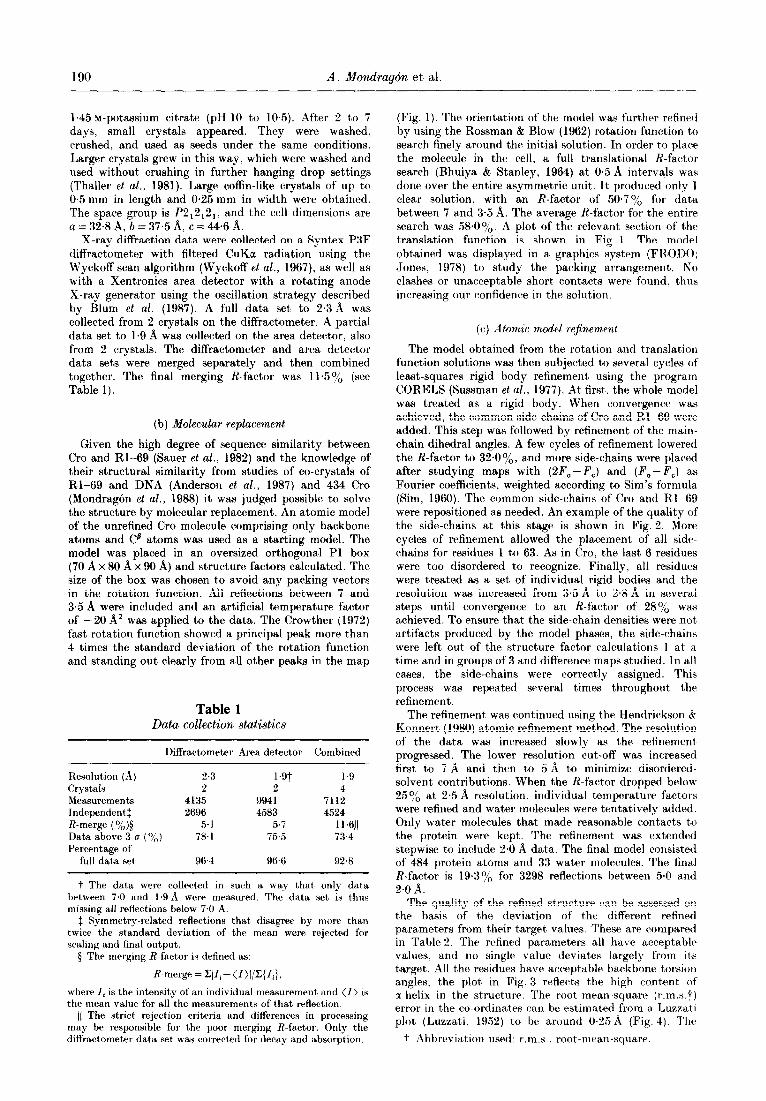
The quality of the relined structure can be assessed on the basis of the deviation of the different refined parameters from their target values. These are compared in Table 2. The refined parameters all have acceptable values. and no single value deviates largely from its target. All the residues have acceptable backbone torsion angles. t#he plot’ in Fig. 3 reflects t,he high content of cc-helix in the structure. The root-mean-square (r.m.s.7) error in the co-ordinat,es can be estimated from a Luzzat,i plot (Luzzati, 1952) to be around 0.25 A (Fig. 4). Thcs
t Abbreviation used: r.m.s.. root-mean-square.

434 Repressor Amino-terminal Domain Structure 191
60
0 60
0.250
0.125
o*ooo
180
Gamma (deg.)
240 300 360
0.125 0.250
x (fractional)
0. 375 0.500
Figure 1. Rl-69 rotation and translation functions. The main-chain atoms and C8 atoms of the unrefined 434 Cro protein were used as search structure. All data between 7.0 and 3.5 A were included. (a) Section of Crowther (1972) fast rotation function. The peak shown is the highest in the entire map. The contour levels are at 0.5 0 intervals and start at the 1.5 0 level. The section corresponds to /I = 50 in Crowther’s Eulerian angle convention. An artificial temperature factor of -20 A2 was applied to the data to sharpen the peaks. (b) Section of R-factor search map (Bhuiya & Stanley, 1964). Only part of the section with the highest peak is shown. The function plotted is (lOO.O-R-factor). The contour levels are at 0x5 unit and st#art at 46. The highest peak corresponds to an R-factor of 50.7%, and the mean value for the entire map is SS.Oo/,. The section corresponds to z = 0.1666.
Figure 2. Part of a (W,-F,) map during refinement. The map was calculated using phases obtained from a partial model of the structure that did not include all side-chains. The final, refined model is shown in thin lines and the partial model in thick lines. The region is representative of other parts of the map at a comparable stage of the refinement.

192 A. Mondragdn et al.
Table 2 Refinement results
Parameter Target sigma Final model Number
Bonding distances (A) Bond length 042 O+KJ7 488 Angle-related distance 0.04 0.027 656 Intraplanar distance 0.05 0.030 145
Planar groups Deviation from plane (8) 0.02 0.005 82
Chiral centres Chiral volume (A3) 0.15 0.101 78
Non-bonded contacts (A) Single torsion 0.50 0.173 171 Multiple torsion 0.50 0.287 192 Possible hydrogen bond 0.50 0.248 36
Angles (deg.) Planar 3.0 1.1 66 Staggered 15.0 15.8 101 Transverse 20.0 12.0 2
Thermal factors (isotropic) (A*)
Main-chain bond 5.0 2.32 259 Main-chain angle 10.0 3.34 326 Side-chain bond 5.0 3.32 230 Side-chain angle IO.0 4.84 332
The values shown correspond to the last cycle of refinement. A total of 484 protein atoms in 63 residues and 33 water molecules are included.
180
60
-60
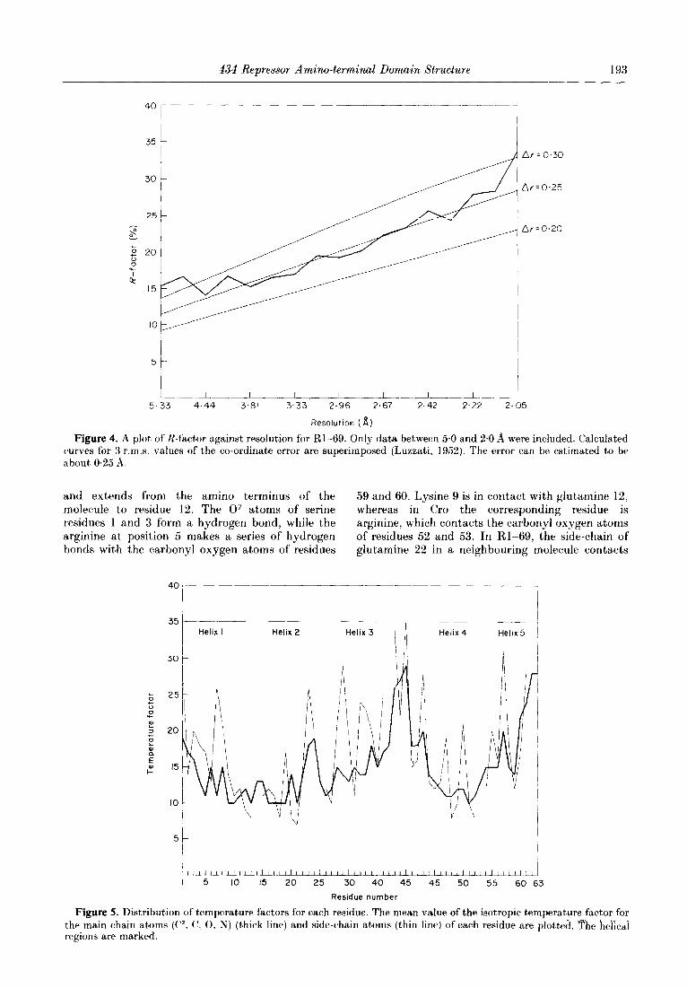
distribution of the temperature factors is shown in Fig. 5, the plot shows the average value for t)he main-chain atoms and side-chain atoms separately.
3. Results
(a) 23ructure of 434 R l-69
As expected, Rl-69 is very similar to 434 Cro. The chain folds into five a-helices, which include two that form a helix-turn-helix motif. The C” trace of the molecule is shown in Figure 6. The five helices consist of residues 1 to 12, 16 to 22, 29 to 36, 45 to 51 and 56 to 61. Helices 2 and 3 form the helix-turn-helix region. The general fold of the protein had already been observed in the co-crystals of Rl-69 and DNA (Anderson et al., 1987) except for helix 5, which had not been identified due to uncertainties in fitting the carboxy-terminal region in t,heir map. The assignment of residues to helices is based on backbone torsion angles as well as possible hydrogen bonds. Because of the higher resolution and accuracy of this model, the assign- ment supersedes that of Anderson et al. (1987). The last six residues of Rl-69 are disordered in t,he crystal.
The helices form a compact protein with a hydrophobic interior. The hydrophobic side-chains are shown in Figure 7. The first helix is the longest
1
-180 -I 20 -60 0 60 120 I80
Phi (deg.)
Figure 3. Rl-69 Ramachandran plot. The preferred conformation regions are outlined. Glycine residues are plotted with boxes. all other residues with stars.
434 Repressor Amino-terminal Domain Structure 193
Ar=0.30
Ar=0,25
Ar10.20
5 c
5.33 4.44 3.81 3.33 2.96 2.67 2.42 2.22 2.05
Resolution ( fi)
Figure 4. A plot of R-factor against resolution for Rl-69. Only data between 5.0 and 2.0 A were included. Calculated curves for 3 r.m.s. values of the co-ordinate error are superimposed (Luzzati, 1952). The error can be estimated to be about 0.25 A.
and extends from the amino terminus of the 59 and 60. Lysine 9 is in contact with glutamine 12, molecule to residue 12. The Oy atoms of serine whereas in Cro the corresponding residue is residues 1 and 3 form a hydrogen bond, while the arginine, which contacts the carbonyl oxygen atoms arginine at position 5 makes a series of hydrogen of residues 52 and 53. In Rl-69, the side-chain of bonds with the carbonyl oxygen atoms of residues glutamine 22 in a neighbouring molecule contacts
35'
t
-~- ___ -__~ Helix I Helix 2 Helix 3
30 c
Helix 4
! Helix5 1
J
Residue number
Figure 5. Distribution of temperature factors for each residue. The mean value of the isotropic tempera,ture factor for - -. the main chain at,oms (P- C’. 0, N) (thick line) and side-chain atoms (thin line) of each residue are $ot,ted. The hej&ai regions are marked.
194 A. Mondragdn et al
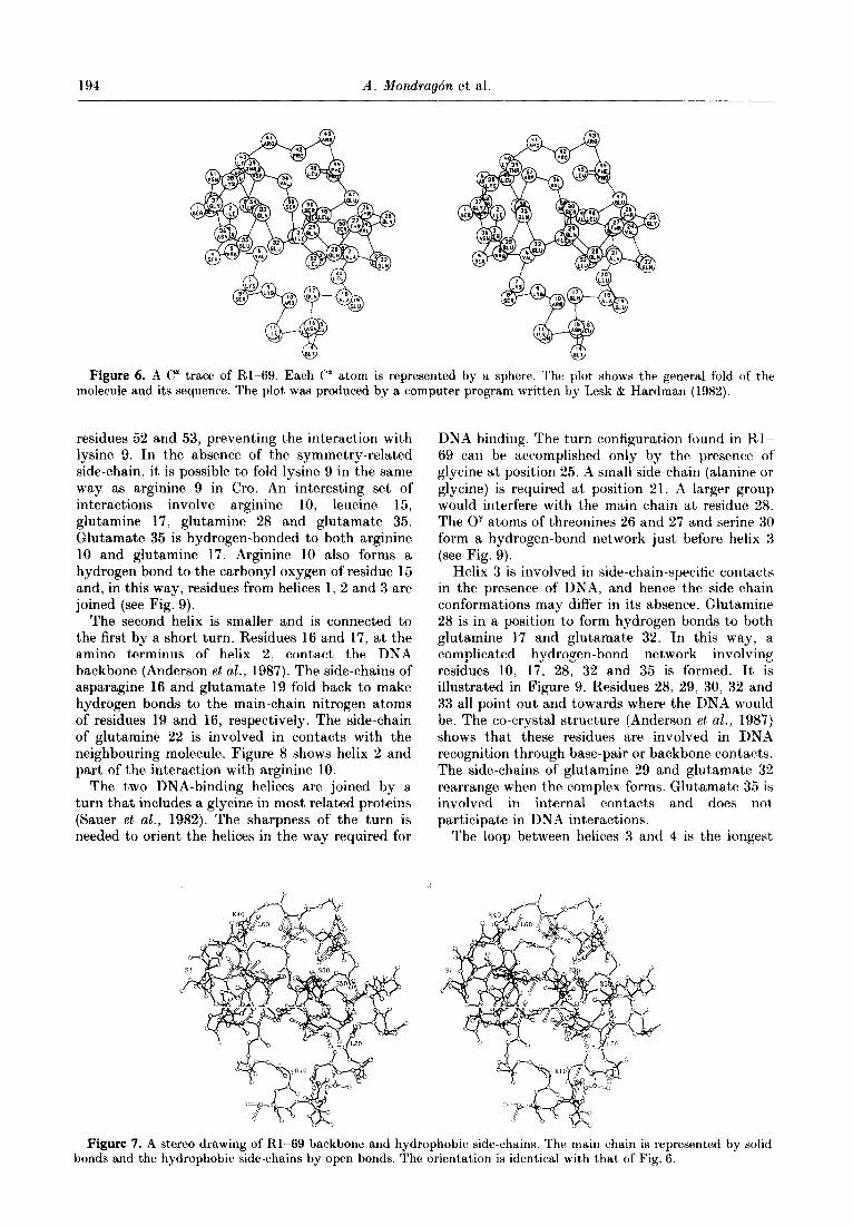
Figure 6. A C” trace of’ Rl-69. Each C” atom is represented by a sphere. The plot shows the general fold molecule and its sequence. The plot was produced by a computer program written by Lesk & Hardman (1982).
residues 52 and 53, preventing the interaction with lysine 9. In the absence of the symmetry-related side-chain, it is possible to fold lysine 9 in the same way as arginine 9 in Cro. An interesting set of interactions involve arginine 10, leucine 15, glutamine 17, glutamine 28 and glutamate 35. Glutamate 35 is hydrogen-bonded to both arginine 10 and glutamine 17. Arginine 10 also forms a hydrogen bond to the carbonyl oxygen of residue 15 and, in this way, residues from helices 1, 2 and 3 are joined (see Fig. 9).
The second helix is smaller and is connected to the first by a short turn. Residues 16 and 17, at the amino terminus of helix 2, contact the DNA backbone (Anderson et al., 1987). The side-chains of asparagine 16 and glutamate 19 fold back to make hydrogen bonds to the main-chain nitrogen atoms of residues 19 and 16, respectively. The side-chain of glutamine 22 is involved in contacts with the neighbouring molecule. Figure 8 shows helix 2 and part of the interaction with arginine 10.
The two DNA-binding helices are joined by a turn that includes a glycine in most related proteins (Sauer et al., 1982). The sharpness of the turn is needed to orient the helices in the way required for
of t,he
DNA binding. The turn configuration found in Rl-- 69 can be accomplished only by the presence of glycine at position 25. A small side-chain (alanine or glycine) is required at position 21. A larger group would interfere with the main chain at residue 28. The Oy atoms of threonines 26 and 27 and serine 30 form a hydrogen-bond network just before helix 3 (see Fig. 9).
Helix 3 is involved in side-chain-specific contacts in the presence of DNA, and hence the side-chain conformations may differ in its absence. Glutamine 28 is in a position to form hydrogen bonds to both glutamine 17 and glutamate 32. In this way, a complicated hydrogen-bond network involving residues 10, 17, 28, 32 and 35 is formed. It is illustrated in Figure 9. Residues 28, 29, 30, 32 and 33 all point out and towards where the DNA would be. The co-crystal structure (Anderson et al., 1987) shows that these residues are involved in DNA recognition through base-pair or backbone contacts. The side-chains of glutamine 29 and glutamate 32 rearrange when the complex forms. Glutamate 35 is involved in internal contacts and does not participate in DNA interactions.
The loop between helices 3 and 4 is the longest
Figure 7. A stereo drawing of Rl-69 backbone and hydrophobic side-chains. The main chain is represented by solid bonds and the hydrophobic side-chains by open bonds. The orientation is identical with that of Fig. 6.

434 Repressor Amino-terminal Domain Structure 195
Figure 8. A stereo drawing of helix 2 of Rl-69. The plot shows the turn linking helix 1 and helix 2. Hydrogen bonds Figure 8. A stereo drawing of helix 2 of Rl-69. The plot shows the turn linking helix 1 and helix 2. Hydrogen bonds are shown with broken lines. The view is along the axis of helix 2 from the amino terminus. Both asparagine 16 and are shown with broken lines. The view is along the axis of helix 2 from the amino terminus. Both asparagine 16 and glutamate 19 form hydrogen bonds with main-chain nitrogen atoms. glutamate 19 form hydrogen bonds with main-chain nitrogen atoms.
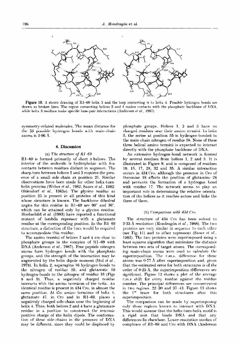
non-helical region in the protein. It interacts with the DNA backbone, and the contacts appear to involve both main-chain nitrogen atoms and the side-chains of lysine 40 and arginines 41 and 43 (Anderson et al., 1987). The side-chains of lysines 38 and 40 are poorly defined in the Rl-69 map, since they face the solvent and do not make contacts with neighbouring molecules. Arginines 41 and 43 are well defined, albeit the former is involved in crystallographic contacts that restrict its conforma- tion. Figure 10 shows helix 3 and the loop that joins helices 3 and 4.
Helix 4 (residues 45 to 50) forms part of the dimer interface when RI-69 is bound to DNA. The helix contains a proline residue at position 46, but it, does not seem to distort the helix in any marked way. The helix ends with a P-like turn and is followed by a short stretch before helix 5. The Oy of serine 55 forms a hydrogen bond with the main- chain nitrogen of residue 58, and in this way caps the amino terminus of helix 5. Helix 5 approaches helix 1 and contacts it through interactions with
arginine 5 and tryptophan 59. The side of’ the indole ring lies against arginine 5, half-buried in the inside of the protein. The helix ends with a turn, and then the polypeptide disappears.
The last six residues are not seen in either Rl-69 or 434 Cro. Since Rl-69 was solved by molecular replacement with the Cro model, especial attention was paid to this region, and several attempts were made to extend the chain, In all cases these proved futile, and the difference maps clearly showed strong negative density for any extra residues after 63. The fact that in other regions of the molecule it was possible to delete residues and still get good density for them in both 2F,- F, and difference maps reinforced the view that these last six residues are indeed disordered.
The water molecules in Rl-69 are mainly attached to main-chain atoms. Of the 33 water molecules identified, 26 are hydrogen-bonded to at least one main-chain carbonyl oxygen or nitrogen. Many of these make more than one hydrogen bond, and in many cases they are trapped between
Figure 9. A stereo drawing of helix 3 of Rl-69, showing the hydrogen-bond network formed by residues of helices 1, 2 and 3. Hydrogen bonds are shown with broken lines. For clarity, only side-chain hydrogen bonds are shown. Kate the extensive network formed by residues 10. 17, 28, 32 and 35. The orientation is similar to that of Figs 6 and 7, with helix 3 across the page.
196 A. Mondrqbn et al.
Figure 10. A stereo drawing of Rl-69 helix 3 and the loop connecting it t,o helix 4. Possible hydrogen bonds are drawn as broken lines. The region connecting helices 3 and 4 makes contacts with the phosphate backbone of DNA. while helix 3 residues make specific base-pair interactions (Anderson et al., 1987).
symmetry-related molecules. The mean distance for the 38 possible hydrogen bonds with main-chain atoms is 2.96 A.
4. Discussion
(a) The structure of RI-69 Rl-69 is formed primarily of short a-helices. The interior of the molecule is hydrophobic with few contacts between residues distant in sequence. The sharp turn between helices 2 and 3 requires the pres- ence of a small side-chain at position 21. Similar observations have been made for other helix-turn- helix proteins (Weber et al., 1982; Sauer et al., 1982; Ohlendorf et al., 1983a). The glycine residue at position 25 is present in all proteins of this kind whose structure is known. The backbone dihedral angles for this residue in Rl-69 are 90” and 36”. which can be attained only by a glycine residue. Hochschild et al. (1983) have reported a functional mutant of lambda repressor with a glutamate residue at the corresponding position. In the Rl-69 structure, a distortion of the turn would be required to accommodate this residue.
The amino termini of helices 2 and 4 are close to phosphate groups in the complex of Rl-69 with DNA (Anderson et al., 1987). Free peptide nitrogen atoms form hydrogen bonds with the phosphate groups, and the strength of the interaction may be augmented by the helix dipole moment (Ho1 et al., 1978). In helix 2, asparagine 16 hydrogen-bonds to the nitrogen of residue 19, and glutamate 19 hydrogen-bonds to the nitrogen of residue 16 (Figs 8 and 9). Thus, a negatively charged residue interacts with the amino terminus of the helix. An identical residue is present in 434 Cro, in almost t,he same position. At the amino terminus of helix 4. glutamate 47, in Cro and in Rl-69, places a negatively charged side-chain near the beginning of helix 4. Thus, both helices 2 and 4 have a glutamate residue in a position to counteract the intrinsic positive charge of the helix dipole. The conforma- tion of these side-chains in the presence of DNA may be different, since they could be displaced by
phosphate groups. Helices 1, 3 and 5 have no charged residues near their amino termini. In helix 5, the serine at position 55 is hydrogen-bonded to the main-chain nitrogen of residue 58. None of these three helical amino termini is expected to interact directly with the phosphate backbone of DNA.
An extensive hydrogen-bond network is formed by several residues from helices 1, 2 and 3. It is illustrated in Figure 9, and is composed of residues 10, 15, 17, 28, 32 and 35. A similar interaction occurs in 434 Cro, although the presence in Cro of threonine 18 affects the position of glutamine 28 and prevents the formation of a hydrogen bond with residue 17. The network seems to play an important role in determining the relative orient,a- tion of the helices as it reaches across and links the three of them.
(b) (lomparison with 434 (Ire
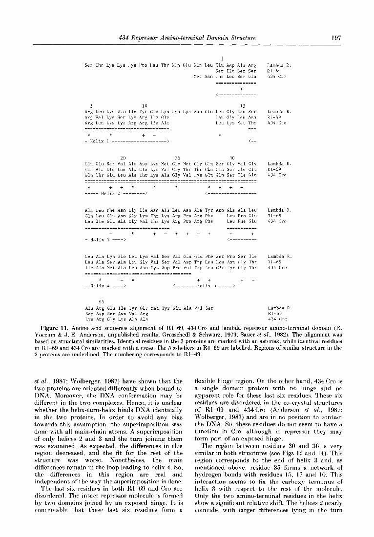
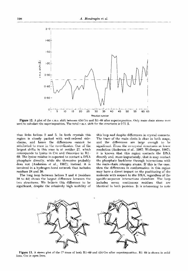
The structure of 434 Cro has been solved to 2.35 A resolution (Mondrag6n et al., 1988). The t’wo proteins are very similar in sequence to each other (see Fig. 11) and to other repressors (Sauer et al.. 1982). The two proteins were superimposed using a least-squares algorithm that minimizes the distance between two sets of target atoms. The correspond- ing main-chain atoms were used to calculate the superimposition. The r.m.s. difference for these atoms was 0.77 A after superimposition and. given that the estimated error for both structures is of the order of 0.25 A, the superimposit’ion differences are significant. Figure 12 shows a plot of t,he average r.m.s shift for every residue against the residue number. The principal differences arc concentrated in t’wo regions, 22-30 and 37-43. Figure 13 shows the C” trace for bot’h structures after this superimposition.
The comparison can be made by superimposing only those regions known to interact with DNA. This would assume that the helix-turn-helix motif is a rigid unit that binds DNA and that an) differences lie elsewhere. Lower-resolution studies of complexes of R*l-69 and Cro with DNA (Anderson
434 Repressor Amino-terminal Domain Structure
1
Ser Thr Lys Lys Lys Pro Leu Thr Gin Glu Gin Leu Glu Asp Ala Arg Ser Ile Ser Ser
Met Asn Thr Leu Ser Glu --------------- ---------------
+ <--------------
5 10 15 Arg Leu Lys Aia Ile Tyr Glu Lys Lys Lys Asn Glu Leu Gly Leu Ser Arg Val Lys Ser Lys Arg Ile Gin Leu Gly Leu Asn Arg Leu Lys Lys Arg Arg Ile Ala Leu Lys Met Thr ------------------------------- --- ------------------------------- ---
* * + + * - Helix 1 --------------------> <--
20 25 30 Gln Glu Ser Val Ala Asp Lys Met Gly Met Gly Gln Ser Gly Val Gly Gln Ala Glu Leu Ala Gln Lys Val Gly Thr Thr Gin Gin Ser Ile Cl.1 Gin Thr Glu Leu Ala Thr Lys Ala Gly Val Lys Gin Gln Ser Ile Llv ___-____-____-____-_____________________----------------------- --_--___---__--__----------------------------------------------
* t + * * * * + t t ---__ Helix 2 --------> <------------------
Ala Leu Phe Asn Gly Ile Asn Ala Leu Asn Ala Tyr Asn Ala Ala Leu Gln Leu Glu Asn Gly Lys Thr Lys Arg Pro Arg Phe Leu Pro Glu Leu Ile Glu Ala Gly Val Thr Lys Arg Pro Arg Phe Leu Phe Glu -----------_----_-------------- ----------- ---_---_----_----_------------- --_---__---
i * t + + t t + + t - Helix 3 ----> <----------
Leu Ala Lys Ile Leu Lys Val Ser Val Glu Glu Phe Ser Pro Ser Ile Leu Ala Ser Ala Leu Gly Val Sex- Val Asp Trp Leu Leu Asn Gly Thr Ile Ala Met Ala Leu Asn Cys Asp Pro Val Trp Leu Gln Tyr Gly Thr --------------------------------------- ---------------------------------------
* + * t t t t - Helix 4 ----> <------- Helix 5 -----;a
65 Ala Arg Glu Ile Tyr Glu Met Tyr Glu Ala Val Ser Ser Asp Ser Asn Val Arg Lys Arg Gly Lys Ala Ala
- 197
Lambda R. Rl-69 434 Cm
Lambda R Rl-69 434 Cro
Lambda R. Rl-69 434 Cro
Lambda R. Rl-69 434 Cro
Lambda R. Rl-69 434 Cro
Lambda R. Rl-69 434 Cro
Figure 11. Amino acid sequence alignment of Rl-69, 434 Cro and lambda repressor amino-terminal domain (R. Yoccum & J. E. Anderson, unpublished results; Grosschedl & Schwarz, 1979; Sauer et al., 1982). The alignment was based on structural similarities. Identical residues in the 3 proteins are marked with an asterisk, while identical residues in RI-69 and 434 Cro are marked with a cross. The 5 a-helices in Rl-69 are labelled. Regions of similar structure in the 3 proteins are underlined. The numbering corresponds to RI-69.
et al., 1987; Wolberger, 1987) have shown that the two proteins are oriented differently when bound to DNA. Moreover, the DNA conformation may be different in the two complexes. Hence, it is unclear whether the helix-turn-helix binds DNA identically in the two proteins. In order to avoid any bias towards this assumption, the superimposition was done with all main-chain atoms. A superimposition of only helices 2 and 3 and the turn joining them was examined. As expected, the differences in this region decreased, and the fit for the rest of the structure was worse. Nonetheless, the main differences remain in the loop leading to helix 4. So, the differences in this region are real and independent of the way the superimposition is done.
The last six residues in both Rl-69 and Cro are disordered. The intact repressor molecule is formed by two doma,ins joined by an exposed hinge. It is conceivable that these last six residues form a
flexible hinge region. On the other hand, 434 Cro is a single domain protein with no hinge and no apparent role for these last six residues. These six residues are disordered in the co-crystal structures of Rl-69 and 434Cro (Anderson et al., 1987; Wolberger, 1987) and are in no position to contact the DNA. So, these residues do not seem to have a function in Cro, although in repressor t’hey may form part of an exposed hinge.
The region between residues 30 and 36 is very similar in both structures (see Figs 12 and 14). This region corresponds to the end of helix 3 and, as mentioned above, residue 35 forms a network of hydrogen bonds with residues 15, 17 and 10. This interaction seems to fix the carboxy terminus of helix 3 with respect to the rest of the molecule. Only the two amino-terminal residues in the helix show a significant relative shift. The helices 2 nearly coincide, with larger differences lping in the turn
198 A. Mondragdn et al.
I- L I
0.60
Residue number
Figure 12. A plot of the r.m.s. shift between 434 Cro and Rl-69 after superimposition. Only main-chain atoms were
used to calculate the superimposition. The total r.m.s. shift for the structures is 0.77 8.
that links helices 2 and 3. In both crystals this region is closely packed with well-ordered side- chains, and hence the differences cannot be attributed to error in the co-ordinates. One of the largest shifts in this zone is at residue 27, which corresponds to lysine in Cro and threonine in Rl- 69. The lysine residue is expected to contact a DNA phosphate directly, while the threonine probably does not (Anderson et al., 1987); instead, it is involved in a hydrogen-bond network that includes residues 28 and 30.
The long loop between helices 3 and 4 (residues 38 to 44) shows the largest difference between the two structures. We believe this difference to be significant, despite the relatively high mobility of
this loop and despite differences in crystal contacts. The trace of the main chain is clear in both maps, and the differences are large enough to be significant. From the co-crystal structures at’ lower resolution (Anderson et aZ., 1987; Wolberger, 1987), it is known that this region contacts the DNA directly and, more importantly, that it, may contact the phosphate backbone through interactions with the main-chain nitrogen atoms. If this is the case, then the differences in conformation in this region may have a direct impact on the positioning of the molecule with respect to the DNA, regardless of the specific-sequence interactions elsewhere. The loop includes seven continuous residues that are identical in both proteins. It is interesting to note
Figure 13. A stereo plot of the C” trace of both RI-69 and 434 Cro after superimposition. Rl-69 is ahown in solid lines. Cro in open lines.

434 Repressor Amino-terminal Domain Structure 199
L R
Figure 14. A stereo plot of a region of Rl-69 and 434 Cro. The drawing shows the interaction between residues 10, 15, 17 and 35. The possible hydrogen bonds are shown with broken lines. Open lines correspond to Cro, and solid lines to Rl-69. The 2 molecules are identical in this region.
that the most similar region in sequence is the most seems to be responsible for the difference in different region in structure. conformation of phenylalanine 44. In Cro, the
The side-chain of phenylalanine 44 has a different isoleucine occupies part of the space that would conformation in the two structures. A difference of otherwise be available for the phenylalanine side- 120” in x1 ca’uses the ring to be exposed at the chain, while in Rl-69 leucine 48 leaves enough outside in Cro and to be buried in the interhelical space for it to fit. region in RI-69. The presence at position 48 of The models for Rl-69 and 434 Cro have 33 and isoleucine in Cro and 1euciQe in Rl-69 at residue 48 17 water molecules, respectively. Of these. four are
Figure 15. A stereo plot of the C” trace of both R1-69 and lambda repressor amino-terminal domain after superimposition. Rl-69 is shown in solid lines, lambda repressor in open lines. The numbering for 434 is shown in capitals, for lambda repressor in lower case.

200 A. Mondraqdn et al.
common to both structures. In all four cases, the water molecules are hydrogen-bonded to main- chain atoms and occupy almost identical positions. Two further water molecules are hydrogen-bonded to the same carbonyl oxygen atoms in both structures, although in different positions. In these cases, it’ was clear that nearby side-chains pre- vented attachment in an identical way.
(c) Comparison with the amino-terminal domain of lambda repressor
Helices 1 to 4 of Rl-69 correspond closely to the first four helices of the DNA-binding domain of lambda repressor (Pabo & Lewis, 1982; Anderson et al., 1985). For a more detailed comparison, we superimposed the structures by a least-squares procedure that minimizes the distance between two sets of target atoms. The following regions were superimposed: 1-12, 17-36 and 45-51 in Rl-69 with 13-24, 33-52 and 62-68 in lambda repressor. These correspond to helices 1 and 4 and the entire helix-turn-helix motif. Only the main-chain atoms were considered for the superimposition.
The superimposition of lambda repressor and Rl-69 is shown in Figure 15. The r.m.s. differences for the superimposed atoms is 1.78 8. The two proteins coincide quite well, especially the core of four helices. Helix 5 in Rl-69 appears to correspond to a single turn of a-helix in lambda repressor, just before its helix 5. In lambda repressor, the loop between helices 3 and 4 has one extra residue and the loop between 1 and 2 has four extra residues, with respect to the loops in Rl-69. On the basis of the structural similarities, the amino-terminal part of the sequences must be
aligned differently from the correspondence pro- posed by Sauer el al. (1982). The alignment is shown in Figure 11. The difference is in the phase of the sequences in helix 1. Lambda repressor has an extra four-residue loop between helices 1 and 2, not accounted for in the original alignment. We note that the conserved salt-bridge between arginine 10 and glutamate 35 in Rl-69 and 434 Cro (Fig. 14) now corresponds to the packing of two aromatic residues in lambda repressor.
We thank J. Anderson, ,J. Kuriyan and C. Thorpe for their help during the various stages of this project, and M. Blum for his assistance with the area detector. We thank A. Aggarwal for many helpful discussions, and M. Ptashnr for support. encouragement and collaboration. A. M. is a Damon Runyon-Walter Winchell Cancer Fund Fellow (DRG-878). This work was supported by NIH grant GM29109 (to S.C.H. and M. Ptashne) and X;F;F grant CHE8509574 (to S.C.H., M. Karplus and D. Wiley).
References
Anderson, .J. E., Ptashnr, M. & Harrison. 8. C. (1984). Proc. Nat. Acad. Sci., I:.S.il. 81. 1307-1311.
Anderson. J. E., Ptashne, M. & Harrison. S. (‘. (1985). Nature (London), 316, 596-601.
Anderson. <J. E.. Ptashne, M. & Harrison, S. (‘. (1987). Xature (London), 326, 846-852.
Anderson, W. F.. Ohlendorf. D. H.. Takeda. Y. & Matthews, B. W. (1981). Nature (London,). 290. 754.-758.
Bhuiya, A. K. t Stanley, E. (1964). Acta C’rystallogr. 17, 746-748.
Rlum, M.. Metcalf. P., Harrison. S. (‘. $ Wiley. I). (‘. (1987). J. Appl. Crystallogr. 20, 235-242.
Crowther. R. A. (1972). In The Molecular Replacement Method (Rossman. M. G.. ed.). pp. 173.-183, Gordon and Breach, New York.
Grosschedl. R. & Schwarz, E. (1979). Sucl. ,4cids Hes. 6. 867.-881.
Hendrickson, W. A. Cyr Konnert, J. H. (1980). In Hiomolesxdar Structure, Function, Clonformation and Evolution (Srinivisan. R.. ed.). vol. 1. pp. 43-57. Pergamon Press, Oxford.
Hochschild, A., Irwin, N;. & Ptashnr, M. (1983). (yell, 32, 319.-325.
HOI. W. G. ,J.. van Duijnen. I’. T. & Berendsen. H. J. V. (1978). Nature (London), 273. 443--446.
Jones. T. A. (1978). J. Appl. C’rystallogr. 11. 268-272. Laughon. A. & Scott. M. P. (1984). ,VakurP (London), 310,
25.- 31 Lesk, A. M. $ Hardman, K. I). (1982). Science. 216.
539~-540. Luzzatti. V. (1952). Acta Crystallogr. 5. 8o’L 810. McKay, D. B. & Rteitz. T. A. (1981). Nature (London),
290. 744-749. MondragOn. A.. IVolberger. (‘. 8 Harrison. S. (‘. (1989).
J. Mol. Biol. 205, 179-188. Ohlendorf, D. H.. Anderson, W. F. b Matthews, B. LV’.
(19830). J. Mol. Evol. 19, 109-114. Ohlendorf, D. H., Anderson, W. F.. Takeda, 1.. 8:
Matthews. 1%. W. (1983b). J. Biomol. Struct. DynawL. 1, ,553~.563.
Pabo, (“. 0. & Lewis. M. (1982). Nature (London), 298, 443-447.
Pt.ashne. M. (1986). A Genetic Sv:itch. Cell Press and Blackwell Scientific Publications. Cambridge. MA.
Rossman. M. G. & Blow. 11. M. (1962). .4cta Crystallogr. 15, 24--31.
Sauer, R. T.. Yocum, R. R.. Doolittle, R. I?., Lewis, M. h Pabo. C’. 0. (1982). Xature (London), 298, 447--451.
Schevitz. R,. W.. Otwinowski. Z.. Joachimiak. A.. Lawson. C. I,. & Sigler, P. K. (1985). Xaturu
(London), 327; 782-786. Sim, G. A. (1960). Acta C’rystallogr. 13. 511 512. Sussman. .J. L., Holbrook. S. R.. Church. G. M. & Kim. S.
(1977). Ada Crystal&r. sect. A, 3. 800-804. Thaller. (‘.. Weaver. L. H., Eichele. (i.. Wilson, E..
Karlsson. K. & ,Jansonius. J. 1;. (1981). J. Mol. Biol. 147. 46.5469.
Weber. I. T., McKay, L). B. & Steitz. '1'. A. (1982). Xucl. Acids Res. 10, 5085-5102.
Wharton. R. P. & Ptashne. M. (1987). Xaturr (London), 326, 888-891.
LVolberger, (‘. (1987). Ph.D. thesis, Harvard University. Wyckoff, H. W., Doscher, M.. Tsernoglou. D.. Inagami,
T.. ,Johnson. L.. Hardman, K. D.. Allewell. X. M., Kelly. I). M. & Richards, F. M. (1967). J. Mol. Biol. 27. ,563.-578.
Edited by B. W. Mattheux