STRENGTH OF MATERIALS I · Bending moment and shear force in statically determinate beams. Simple...
27
STRENGTH OF MATERIALS – I Subject Code: CE306ES Regulations: R17 - JNTUH Class : II Year B.Tech CE I Semester Department of Civil Engineering BHARAT INSTITUTE OF ENGINEERING AND TECHNOLOGY Ibrahimpatnam - 501 510, Hyderabad STRENGTH OF MATERIALS – I (CE306ES) COURSE PLANNER I. COURSE OVERVIEW: Civil Engineers are required to design structures like building, beams, dams, bridges, etc. The loads coming onto these structures, along with the self-weight, have to be safely transmitted to the ground. A structural engineer must be able to design a structure in such a way that none
Transcript of STRENGTH OF MATERIALS I · Bending moment and shear force in statically determinate beams. Simple...
STRENGTH OF MATERIALS – I
Subject Code: CE306ES
Regulations: R17 - JNTUH
Class : II Year B.Tech CE I Semester
Department of Civil Engineering
BHARAT INSTITUTE OF ENGINEERING AND TECHNOLOGY
Ibrahimpatnam - 501 510, Hyderabad
STRENGTH OF MATERIALS – I (CE306ES) COURSE PLANNER
I. COURSE OVERVIEW:
Civil Engineers are required to design structures like building, beams, dams, bridges, etc. The
loads coming onto these structures, along with the self-weight, have to be safely transmitted
to the ground. A structural engineer must be able to design a structure in such a way that none
of its members fail during load transfer process. This foundational course in civil engineering
is intended to introduce to concepts of stress and strain due to external loading on a structural
member, and their calculations. For this, the concept and calculations of (a) shear force
diagrams and bending moment diagram for different type of beams, (b) bending and shear
stresses in beams, (c) slope and deflection of beams using various methods are covered in
depth. The important calculations of principal stresses and principal strains and the
consequent theory of failures for prediction of the strength of the materials are also discussed.
Through this course content engineers can design the structures for safety and serviceability
II. PREREQUISITE(S): Level Credits Periods/Week Prerequisites
UG 4 4 Engineering
Mechanics
III. COURSE OBJECTIVES:
The objective of the teacher is to impart knowledge and abilities to the students to:
i. Relate mechanical properties of a material with its behaviour under various load types
ii. Classify the types of material according to the modes of failure and stress-strain curves.
iii. Apply the concepts of mechanics to find the stresses at a point in a material of a structural
member
iv. Analyze a loaded structural member for deflections and failure strength
v. Evaluate the stresses & strains in materials and deflections in beam members
vi. Create diagrams for shear force, bending moment, stress distribution, mohr’s circle,
elastic curve
vii. Design simple beam members of different cross-sections to withstand the loads imposed
on them.
IV. COURSE OUTCOMES:
After completing this course the student must demonstrate the knowledge and ability to:
1. Calculate the stress and strain developed in any structural member due to applied external
load.
2. Differentiate the type of beams, and the various loading and support condition upon them.
3. Apply the formulae for beams under different loading condition.
4. Draw shear force diagram and bending moment diagram for different type of beams.
5. Derive the pure bending equation, and on its basis explain the existence of normal stresses
and shear stresses in the different layers of the beam.
6. Explain the importance of and evaluate the section modulus for various beam cross-
sections.
7. Calculate the normal and tangential stresses on an inclined section of a bar under uniaxial,
biaxial, pure shear and plain stress conditions.
8. Evaluate the principal stress and principal strain at a point of a stressed member and draw
the Mohr’s circle of stresses.
9. Predict failure of a material using various theories of failure, and their relative
applications.
10. Calculate the slope and deflection in beams by using methods like Double integration,
Macaulay method, Moment-area method, Conjugate beam, etc.
11. Participate and succeed in competitive examination like GATE,

V. HOW PROGRAM OUTCOMES ARE ASSESSED:
Program Outcomes Level Proficiency
assessed by
PO1
Engineering knowledge: Apply the knowledge of
mathematics, science, engineering fundamentals,
and an engineering specialization to the solution of
complex engineering problems.
H Assignments,
Exams
PO2
Problem analysis: Identify, formulate, review
research literature, and analyze complex
engineering problems reaching substantiated
conclusions using first principles of mathematics,
natural sciences, and engineering sciences.
H Assignments,
Exams
PO3
Design/development of solutions: Design solutions
for complex engineering problems and design
system components or processes that meet the
specified needs with appropriate consideration for
the public health and safety, and the cultural,
societal, and environmental considerations.
H Assignments,
Exams
PO4
Conduct investigations of complex problems: Use
research-based knowledge and research methods
including design of experiments, analysis and
interpretation of data, and synthesis of the
information to provide valid conclusions.
S Discussion
PO5
Modern tool usage: Create, select, and apply
appropriate techniques, resources, and modern
engineering and IT tools including prediction and
modeling to complex engineering activities with an
understanding of the limitations.
S -
PO6
The engineer and society: Apply reasoning
informed by the contextual knowledge to assess
societal, health, safety, legal and cultural issues and
the consequent responsibilities relevant to the
professional engineering practice.
H
Exams,
Assignment,
Discussions
PO7
Environment and sustainability: Understand the
impact of the professional engineering solutions in
societal and environmental contexts, and
demonstrate the knowledge of, and need for
sustainable development.
S Discussions
PO8
Ethics: Apply ethical principles and commit to
professional ethics and responsibilities and norms
of the engineering practice.
S Discussions
PO9
Individual and team work: Function effectively as
an individual, and as a member or leader in diverse
teams, and in multidisciplinary settings.
S Assignment,
Discussions

PO10
Communication: Communicate effectively on
complex engineering activities with the engineering
community and with society at large, such as, being
able to comprehend and write effective reports and
design documentation, make effective
presentations, and give and receive clear
instructions.
S Discussions
PO11
Project management and finance: Demonstrate
knowledge and understanding of the engineering
and management principles and apply these to one’s
own work, as a member and leader in a team, to
manage projects and in multidisciplinary
environments.
S -
PO12
Life-long learning: Recognize the need for, and
have the preparation and ability to engage in
independent and life-long learning in the broadest
context of technological change.
S Discuss
N – Not Applicable
S – Supportive
H - Highly Related
VI. HOW PROGRAM SPECIFIC OUTCOMES ARE ASSESSED:
Program specific outcomes Le
vel
Proficiency
Assessed By
PSO1
UNDERSTANDING: Graduates will have an
ability to understand, analyze and solve problems
using basic mathematics and apply the techniques
related to irrigation, structural design, etc.
H
Lectures,
Assignments
Exams
PSO2
ANALYTICAL SKILLS: Graduates will have an
ability to design civil structures, using construction
components and to meet desired needs within
realistic constraints such as economic,
environmental, social, political, ethical, health and
safety manufacturability and reliability and learn to
work with multidisciplinary teams.
H
Lectures,
Assignments,
Exams
PSO3
BROADNESS: Graduates will have an exposure
to various fields of engineering necessary to
understand the impact of other disciplines on civil
engineering blueprints in a global, economic, and
societal context and to have necessary focus for
postgraduate education and research opportunities
at global level.
S
Lectures,
Guest
Lectures,
Discussions,
Industrial
visits
VII. SYLLABUS:
UNIT – I
Simple Stresses and Strains: Elasticity and plasticity – Types of stresses and strains –
Hooke’s law – stress – strain diagram for mild steel – Working stress – Factor of safety –

Lateral strain, Poisson’s ratio and volumetric strain – Elastic moduli and the relationship
between them – Bars of varying section – composite bars – Temperature stresses. Elastic
constants.
Strain Energy: Resilience – Gradual, sudden, impact and shock loadings – simple
applications.
UNIT – II
Shear Force and Bending Moment: Definition of beam – Types of beams – Concept of
shear force and bending moment – S.F and B.M diagrams for cantilever, simply supported
and overhanging beams subjected to point loads, uniformly distributed load, uniformly
varying loads and combination of these loads – Point of contra flexure – Relation between
S.F., B.M and rate of loading at a section of a beam.
UNIT – III
Flexural Stresses: Theory of simple bending – Assumptions – Derivation of bending
equation: M/I = f/y = E/R - Neutral axis – Determination of bending stresses – Section
modulus of rectangular and circular sections (Solid and Hollow), I,T, Angle and Channel
sections – Design of simple beam sections.
Shear Stresses: Derivation of formula – Shear stress distribution across various beam
sections like rectangular, circular, triangular, I, T angle sections.
UNIT – IV
Deflection of Beams: Bending into a circular arc – slope, deflection and radius of curvature –
Differential equation for the elastic line of a beam – Double integration and Macaulay’s
methods – Determination of slope and deflection for cantilever and simply supported beams
subjected to point loads, U.D.L, Uniformly varying load-Mohr’s theorems – Moment area
method – application to simple cases including overhanging beams.
Conjugate Beam Method: Introduction – Concept of conjugate beam method. Difference
between a real beam and a conjugate beam. Deflections of determinate beams with constant
and different moments of inertia.
UNIT – V
Principal Stresses and Strains: Introduction – Stresses on an inclined section of a bar under
axial loading – compound stresses – Normal and tangential stresses on an inclined plane for
biaxial stresses – Two perpendicular normal stresses accompanied by a state of simple shear –
Mohr’s circle of stresses – Principal stresses and strains – Analytical and graphical solutions.
Theories of Failure: Introduction – Various theories of failure - Maximum Principal Stress
Theory, Maximum Principal Strain Theory, Maximum shear stress theory- Strain Energy and
Shear Strain Energy Theory (Von Mises Theory).
SUGGESTED BOOKS:
TEXT BOOKS:
1. Mechanics of Materials by B. C. Punmia, A. K. Jain and A. K. Jain, Laxmi Publications
(P) Ltd, New Delhi.
2. Strength of Materials – A Practical Approach Vol.1 by D. S. Prakash Rao, Universities
Press, Hyderabad, India.
3. Mechanics of materials by F. Beer, E. R. Johnston and J. Dewolf (Indian Edition – SI
units), Tata McGraw Hill Publishing Co. Ltd., New Delhi
REFERENCES BOOKS:
1. Mechanics of Materials (SI edition) by J.M. Gere and S. Timoshenko, CL Engineering, India
2. Engineering Mechanics of Solids by E. G. Popov, Pearson Education, New Delhi, India
3. Strength of Materials by R. K. Bansal, Laxmi Publications (P) ltd., New Delhi, India.
4. Strength of Materials by S.S.Bhavikatti, Vikas Publishing House Pvt. Ltd.
5. Strength of Materials by R.K Rajput, S.Chand & Company Ltd.
6. Strength of Materials by R. S. Khurmi, S. Chand publication New Delhi, India.
7. Fundamentals of Solid Mechanics by M.L.Gambhir, PHI Learning Pvt. Ltd
8. Strength of Materials by R.Subramanian, Oxford University Press.
NPTEL WEB COURSE:
http://nptel.ac.in/courses/112107147/37 NPTEL VIDEO COURSE:
http://nptel.ac.in/courses/112107147/37#
GATE SYLLABUS:
Bending moment and shear force in statically determinate beams. Simple stress and strain
relationship: Stress and strain in two dimensions, principal stresses, stress transformation,
Mohr's circle. Simple bending theory, flexural and shear stresses, unsymmetrical bending,
shear centre. Thin walled pressure vessels, uniform torsion, buckling of column, combined
and direct bending stresses
IES SYLLABUS:
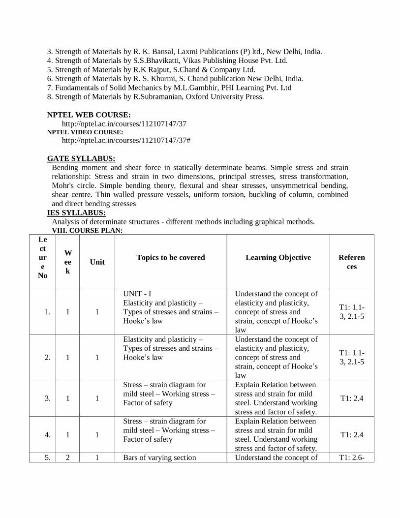
Analysis of determinate structures - different methods including graphical methods. VIII. COURSE PLAN:
Le
ct
ur
e
No
W
ee
k
Unit Topics to be covered
Learning Objective
Referen
ces
1. 1 1
UNIT - I
Elasticity and plasticity –
Types of stresses and strains –
Hooke’s law
Understand the concept of
elasticity and plasticity,
concept of stress and
strain, concept of Hooke’s
law
T1: 1.1-
3, 2.1-5
2. 1 1
Elasticity and plasticity –
Types of stresses and strains –
Hooke’s law
Understand the concept of
elasticity and plasticity,
concept of stress and
strain, concept of Hooke’s
law
T1: 1.1-
3, 2.1-5
3. 1 1
Stress – strain diagram for
mild steel – Working stress –
Factor of safety
Explain Relation between
stress and strain for mild
steel. Understand working
stress and factor of safety.
T1: 2.4
4. 1 1
Stress – strain diagram for
mild steel – Working stress –
Factor of safety
Explain Relation between
stress and strain for mild
steel. Understand working
stress and factor of safety.
T1: 2.4
5. 2 1 Bars of varying section Understand the concept of T1: 2.6-
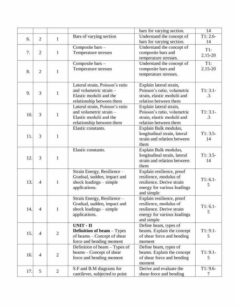
bars for varying section. 14
6. 2 1 Bars of varying section Understand the concept of
bars for varying section.
T1: 2.6-
14
7. 2 1
Composite bars –
Temperature stresses
Understand the concept of
composite bars and
temperature stresses.
T1:
2.15-20
8. 2 1
Composite bars –
Temperature stresses
Understand the concept of
composite bars and
temperature stresses.
T1:
2.15-20
9. 3 1
Lateral strain, Poisson’s ratio
and volumetric strain –
Elastic modulii and the
relationship between them
Explain lateral strain,
Poisson’s ratio, volumetric
strain, elastic modulii and
relation between them
T1: 3.1-
.3
10. 3 1
Lateral strain, Poisson’s ratio
and volumetric strain –
Elastic modulii and the
relationship between them
Explain lateral strain,
Poisson’s ratio, volumetric
strain, elastic modulii and
relation between them
T1: 3.1-
.3
11. 3 1
Elastic constants. Explain Bulk modulus,
longitudinal strain, lateral
strain and relation between
them
T1: 3.5-
14
12. 3 1
Elastic constants. Explain Bulk modulus,
longitudinal strain, lateral
strain and relation between
them
T1: 3.5-
14
13. 4 1
Strain Energy, Resilience –
Gradual, sudden, impact and
shock loadings – simple
applications.
Explain resilience, proof
resilience, modulus of
resilience. Derive strain
energy for various loadings
and simple
T1: 6.1-
5
14. 4 1
Strain Energy, Resilience –
Gradual, sudden, impact and
shock loadings – simple
applications.
Explain resilience, proof
resilience, modulus of
resilience. Derive strain
energy for various loadings
and simple
T1: 6.1-
5
15. 4 2
UNIT - II
Definition of beam – Types
of beams – Concept of shear
force and bending moment
Define beam, types of
beams. Explain the concept
of shear force and bending
moment
T1: 9.1-
5
16. 4 2
Definition of beam – Types of
beams – Concept of shear
force and bending moment
Define beam, types of
beams. Explain the concept
of shear force and bending
moment
T1: 9.1-
5
17. 5 2 S.F and B.M diagrams for
cantilever, subjected to point
Derive and evaluate the
shear-force and bending
T1: 9.6-
7

loads, uniformly distributed
load, uniformly varying loads
and combination of these
loads – Point of contra flexure
moment for cantilever
beam for various types of
loading and solved
problems
18. 5 2
S.F and B.M diagrams for
cantilever, subjected to point
loads, uniformly distributed
load, uniformly varying loads
and combination of these
loads – Point of contra flexure
Derive and evaluate the
shear-force and bending
moment for cantilever
beam for various types of
loading and solved
problems
T1: 9.6-
7
19. 5 2
S.F and B.M diagrams for
cantilever, subjected to point
loads, uniformly distributed
load, uniformly varying loads
and combination of these
loads – Point of contra flexure
Derive and evaluate the
shear-force and bending
moment for cantilever
beam for various types of
loading and solved
problems
T1: 9.6-
7
20. 5 2
S.F and B.M diagrams simply
supported subjected to point
loads, uniformly distributed
load, uniformly varying loads
and combination of these
loads – Point of contra flexure
Derive and evaluate the
shear-force and bending
moment for simply
supported beam for various
types of loading and solved
problems
T1: 9.6-
7
21. 6 2
S.F and B.M diagrams simply
supported subjected to point
loads, uniformly distributed
load, uniformly varying loads
and combination of these
loads – Point of contra flexure
Derive and evaluate the
shear-force and bending
moment for simply
supported beam for various
types of loading and solved
problems
T1: 9.6-
7
22. 6 2
S.F and B.M diagrams simply
supported subjected to point
loads, uniformly distributed
load, uniformly varying loads
and combination of these
loads – Point of contra flexure
Derive and evaluate the
shear-force and bending
moment for simply
supported beam for various
types of loading and solved
problems
T1: 9.6-
7
23. 6 2
S.F and B.M diagrams for
overhanging beams subjected
to point loads, uniformly
distributed load, uniformly
varying loads and
combination of these loads –
Point of contra flexure
Derive and evaluate the
shear-force and bending
moment for overhanging
beam for various types of
loading and solved
problems
T1: 9.6-
7
24. 6 2
S.F and B.M diagrams for
overhanging beams subjected
to point loads, uniformly
distributed load, uniformly
varying loads and
Derive and evaluate the
shear-force and bending
moment for overhanging
beam for various types of
loading and solved
T1: 9.6-
7

combination of these loads –
Point of contra flexure
problems
25. 7 2
S.F and B.M diagrams for
overhanging beams subjected
to point loads, uniformly
distributed load, uniformly
varying loads and
combination of these loads –
Point of contra flexure
Derive and evaluate the
shear-force and bending
moment for overhanging
beam for various types of
loading and solved
problems
T1: 9.6-
7
26. 7 2
Relation between S.F., B.M
and rate of loading at a
section of a beam.
Explain the relation
between shear force and
bending moment and rate
of loading at a section for
beams
T1:9.6-
11
27. 7 3
UNIT -III
FLEXURAL STRESSES: Theory of simple bending –
Assumptions – Derivation of
bending equation: M/I = f/y =
E/R
Explain the concept of
simple bending with
assumptions and derive the
bending equation
T1:
10.1-5
28. 7 3
Theory of simple bending –
Assumptions – Derivation of
bending equation: M/I = f/y =
E/R
Explain the concept of
simple bending with
assumptions and derive the
bending equation
T1:
10.1-5
29. 8 3
Neutral axis – Determination
of bending stresses
Define neutral axis and
determine the bending
stresses for various
conditions
T1:
10.5-7
30. 8 3
Neutral axis – Determination
of bending stresses
Define neutral axis and
determine the bending
stresses for various
conditions
T1:
10.5-7
31. 8 3
Section modulus of
rectangular and circular
sections (Solid and Hollow),
I,T, Angle and Channel
sections
Derive the section modulus
for rectangular, circular, I,
T sections and solved
problems
T1: 10.7
32. 8 3
Section modulus of
rectangular and circular
sections (Solid and Hollow),
I,T, Angle and Channel
sections
Derive the section modulus
for rectangular, circular, I,
T sections and solved
problems
T1: 10.7
33. 9 3 Design of simple beam
sections.
Solve problems for design
of simple beams T1: 10.7
34. 9 3 Design of simple beam
sections.
Solve problems for design
of simple beams T1: 10.7

35. 9 3
SHEAR STRESSES:
Derivation of formula – Shear
stress distribution across
various beam sections like
rectangular, circular,
triangular, I, T angle sections.
Derive the formula for
shear stress and evaluate
the shear stress distribution
across various beam
sections like rectangular,
circular, triangular, I, T
angle sections.
T1:
11.1-7
36. 9 3
Derivation of formula – Shear
stress distribution across
various beam sections like
rectangular, circular,
triangular, I, T angle sections.
Derive the formula for
shear stress and evaluate
the shear stress distribution
across various beam
sections like rectangular,
circular, triangular, I, T
angle sections.
T1:
11.1-7
37. 1
0 3
Derivation of formula – Shear
stress distribution across
various beam sections like
rectangular, circular,
triangular, I, T angle sections.
Derive the formula for
shear stress and evaluate
the shear stress distribution
across various beam
sections like rectangular,
circular, triangular, I, T
angle sections.
T1:
11.1-7
38. 1
0 3
Derivation of formula – Shear
stress distribution across
various beam sections like
rectangular, circular,
triangular, I, T angle sections.
Derive the formula for
shear stress and evaluate
the shear stress distribution
across various beam
sections like rectangular,
circular, triangular, I, T
angle sections.
T1:
11.1-7
39. 1
0 4
UNIT-IV
PRINCIPAL STRESSES
AND STRAINS: Introduction
– Stresses on an inclined
section of a bar under axial
loading – compound stresses
Define principal stresses
and strains. Explain the
stresses on a inclined
section of a bar under axial
loading and explain the
concept of compound
stresses
T1: 4.1
40. 1
0 4
Normal and tangential
stresses on an inclined plane
for biaxial stresses – Two
perpendicular normal stresses
accompanied by a state of
simple shear - Mohr’s circle
of stresses, Principal stresses
Evaluate Normal and
tangential stresses on an
inclined plane for biaxial
stresses and evaluate
stresses for two
perpendicular normal
stresses accompanied by a
state of simple shear
T1: 4.2 -
4.11
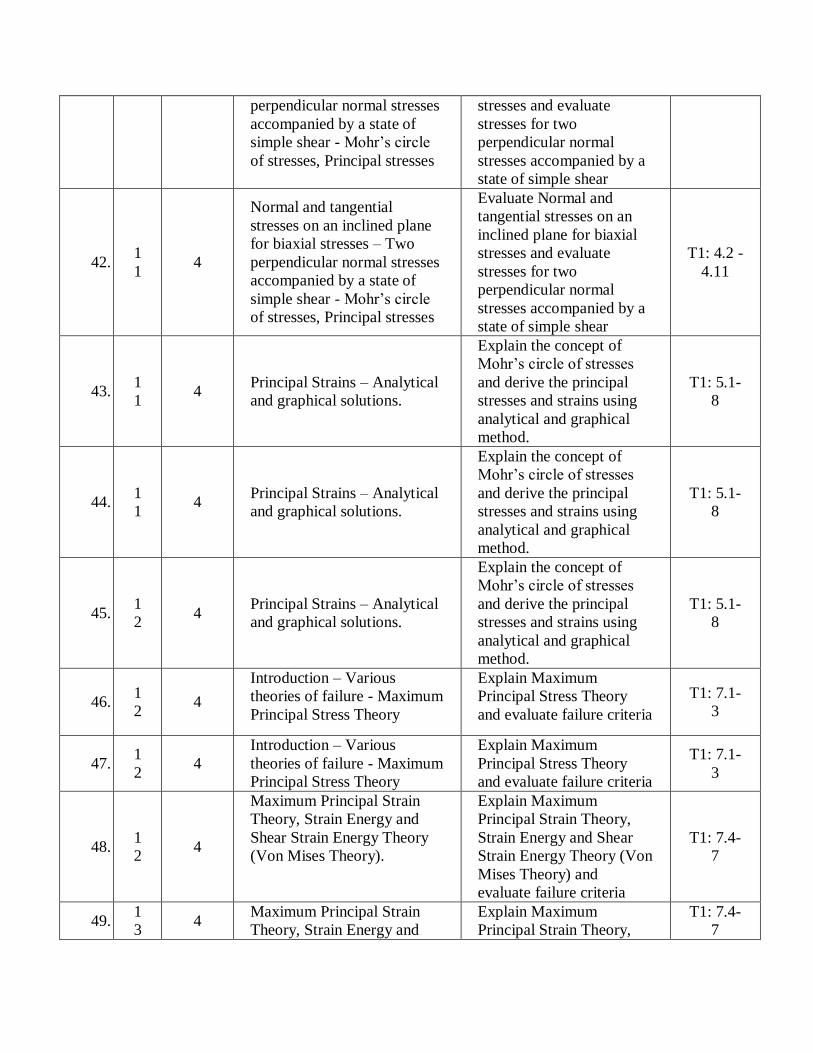
41. 1
1 4
Normal and tangential
stresses on an inclined plane
for biaxial stresses – Two
Evaluate Normal and
tangential stresses on an
inclined plane for biaxial
T1: 4.2 -
4.11
perpendicular normal stresses
accompanied by a state of
simple shear - Mohr’s circle
of stresses, Principal stresses
stresses and evaluate
stresses for two
perpendicular normal
stresses accompanied by a
state of simple shear
42. 1
1 4
Normal and tangential
stresses on an inclined plane
for biaxial stresses – Two
perpendicular normal stresses
accompanied by a state of
simple shear - Mohr’s circle
of stresses, Principal stresses
Evaluate Normal and
tangential stresses on an
inclined plane for biaxial
stresses and evaluate
stresses for two
perpendicular normal
stresses accompanied by a
state of simple shear
T1: 4.2 -
4.11
43. 1
1 4
Principal Strains – Analytical
and graphical solutions.
Explain the concept of
Mohr’s circle of stresses
and derive the principal
stresses and strains using
analytical and graphical
method.
T1: 5.1-
8
44. 1
1 4
Principal Strains – Analytical
and graphical solutions.
Explain the concept of
Mohr’s circle of stresses
and derive the principal
stresses and strains using
analytical and graphical
method.
T1: 5.1-
8
45. 1
2 4
Principal Strains – Analytical
and graphical solutions.
Explain the concept of
Mohr’s circle of stresses
and derive the principal
stresses and strains using
analytical and graphical
method.
T1: 5.1-
8
46. 1
2 4
Introduction – Various
theories of failure - Maximum
Principal Stress Theory
Explain Maximum
Principal Stress Theory
and evaluate failure criteria
T1: 7.1-
3
47. 1
2 4
Introduction – Various
theories of failure - Maximum
Principal Stress Theory
Explain Maximum
Principal Stress Theory
and evaluate failure criteria
T1: 7.1-
3
48. 1
2 4
Maximum Principal Strain
Theory, Strain Energy and
Shear Strain Energy Theory
(Von Mises Theory).
Explain Maximum
Principal Strain Theory,
Strain Energy and Shear
Strain Energy Theory (Von
Mises Theory) and
evaluate failure criteria
T1: 7.4-
7
49. 1
3 4
Maximum Principal Strain
Theory, Strain Energy and
Explain Maximum
Principal Strain Theory,
T1: 7.4-
7
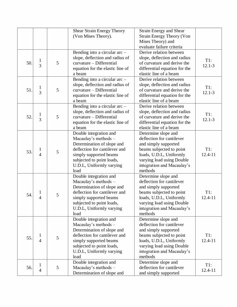
Shear Strain Energy Theory
(Von Mises Theory).
Strain Energy and Shear
Strain Energy Theory (Von
Mises Theory) and
evaluate failure criteria
50. 1
3 5
Bending into a circular arc –
slope, deflection and radius of
curvature – Differential
equation for the elastic line of
a beam
Derive relation between
slope, deflection and radius
of curvature and derive the
differential equation for the
elastic line of a beam
T1:
12.1-3
51. 1
3 5
Bending into a circular arc –
slope, deflection and radius of
curvature – Differential
equation for the elastic line of
a beam
Derive relation between
slope, deflection and radius
of curvature and derive the
differential equation for the
elastic line of a beam
T1:
12.1-3
52. 1
3 5
Bending into a circular arc –
slope, deflection and radius of
curvature – Differential
equation for the elastic line of
a beam
Derive relation between
slope, deflection and radius
of curvature and derive the
differential equation for the
elastic line of a beam
T1:
12.1-3
53. 1
4 5
Double integration and
Macaulay’s methods –
Determination of slope and
deflection for cantilever and
simply supported beams
subjected to point loads,
U.D.L, Uniformly varying
load
Determine slope and
deflection for cantilever
and simply supported
beams subjected to point
loads, U.D.L, Uniformly
varying load using Double
integration and Macaulay’s
methods
T1:
12.4-11
54. 1
4 5
Double integration and
Macaulay’s methods –
Determination of slope and
deflection for cantilever and
simply supported beams
subjected to point loads,
U.D.L, Uniformly varying
load
Determine slope and
deflection for cantilever
and simply supported
beams subjected to point
loads, U.D.L, Uniformly
varying load using Double
integration and Macaulay’s
methods
T1:
12.4-11
55. 1
4 5
Double integration and
Macaulay’s methods –
Determination of slope and
deflection for cantilever and
simply supported beams
subjected to point loads,
U.D.L, Uniformly varying
load
Determine slope and
deflection for cantilever
and simply supported
beams subjected to point
loads, U.D.L, Uniformly
varying load using Double
integration and Macaulay’s
methods
T1:
12.4-11
56. 1
4 5
Double integration and
Macaulay’s methods –
Determination of slope and
Determine slope and
deflection for cantilever
and simply supported
T1:
12.4-11
deflection for cantilever and
simply supported beams
subjected to point loads,
U.D.L, Uniformly varying
load
beams subjected to point
loads, U.D.L, Uniformly
varying load using Double
integration and Macaulay’s
methods
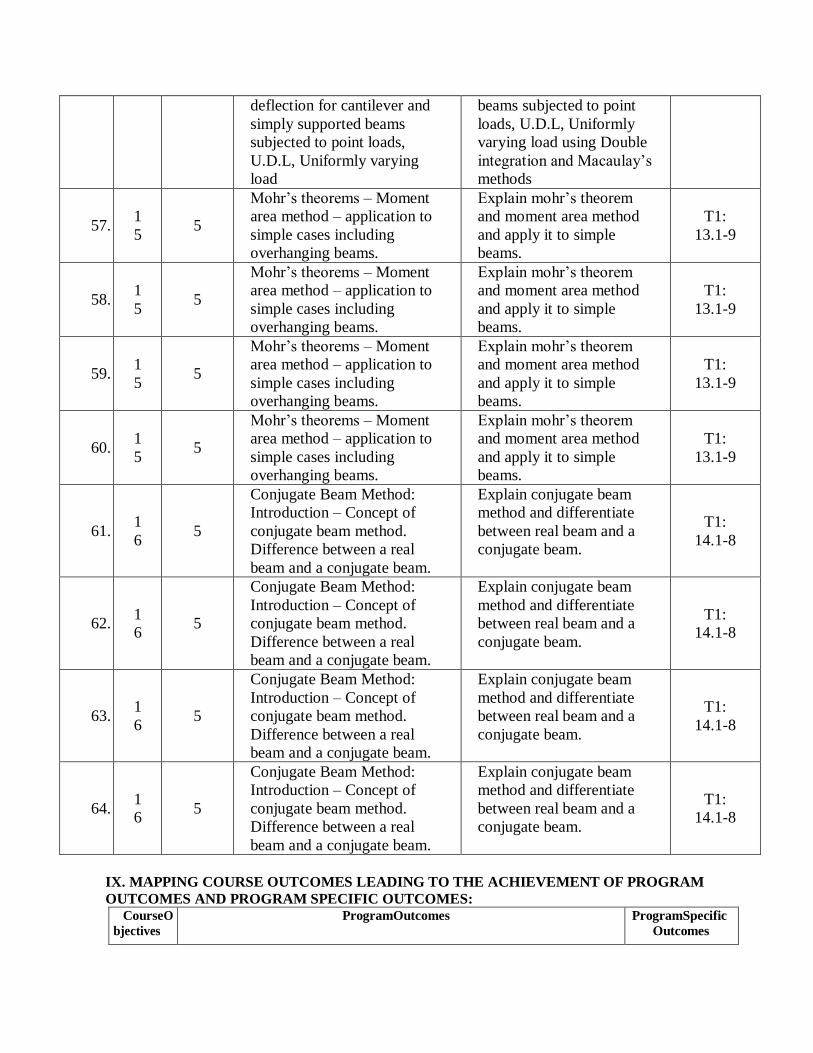
57. 1
5 5
Mohr’s theorems – Moment
area method – application to
simple cases including
overhanging beams.
Explain mohr’s theorem
and moment area method
and apply it to simple
beams.
T1:
13.1-9
58. 1
5 5
Mohr’s theorems – Moment
area method – application to
simple cases including
overhanging beams.
Explain mohr’s theorem
and moment area method
and apply it to simple
beams.
T1:
13.1-9
59. 1
5 5
Mohr’s theorems – Moment
area method – application to
simple cases including
overhanging beams.
Explain mohr’s theorem
and moment area method
and apply it to simple
beams.
T1:
13.1-9
60. 1
5 5
Mohr’s theorems – Moment
area method – application to
simple cases including
overhanging beams.
Explain mohr’s theorem
and moment area method
and apply it to simple
beams.
T1:
13.1-9
61. 1
6 5
Conjugate Beam Method:
Introduction – Concept of
conjugate beam method.
Difference between a real
beam and a conjugate beam.
Explain conjugate beam
method and differentiate
between real beam and a
conjugate beam.
T1:
14.1-8
62. 1
6 5
Conjugate Beam Method:
Introduction – Concept of
conjugate beam method.
Difference between a real
beam and a conjugate beam.
Explain conjugate beam
method and differentiate
between real beam and a
conjugate beam.
T1:
14.1-8
63. 1
6 5
Conjugate Beam Method:
Introduction – Concept of
conjugate beam method.
Difference between a real
beam and a conjugate beam.
Explain conjugate beam
method and differentiate
between real beam and a
conjugate beam.
T1:
14.1-8
64. 1
6 5
Conjugate Beam Method:
Introduction – Concept of
conjugate beam method.
Difference between a real
beam and a conjugate beam.
Explain conjugate beam
method and differentiate
between real beam and a
conjugate beam.
T1:
14.1-8
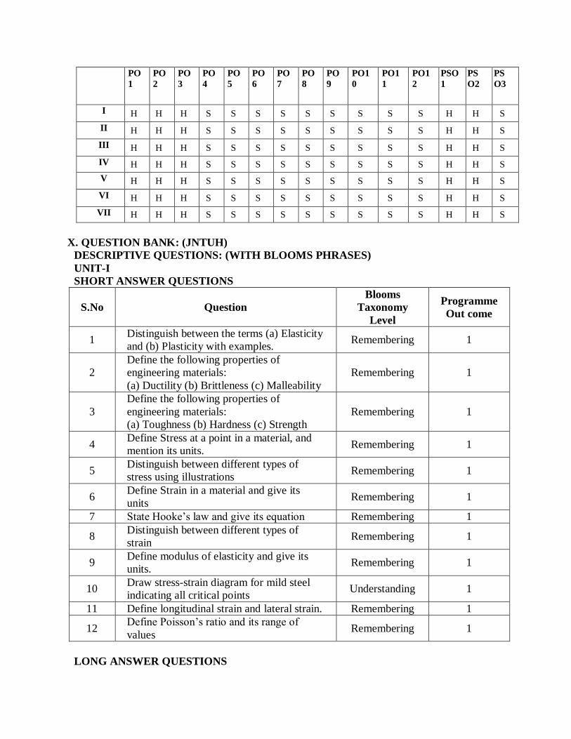
IX. MAPPING COURSE OUTCOMES LEADING TO THE ACHIEVEMENT OF PROGRAM
OUTCOMES AND PROGRAM SPECIFIC OUTCOMES: CourseO
bjectives
ProgramOutcomes ProgramSpecific
Outcomes
PO
1
PO
2
PO
3
PO
4
PO
5
PO
6
PO
7
PO
8
PO
9
PO1
0
PO1
1
PO1
2
PSO
1
PS
O2
PS
O3
I H H H S S S S S S S S S H H S
II H H H S S S S S S S S S H H S
III H H H S S S S S S S S S H H S
IV H H H S S S S S S S S S H H S
V H H H S S S S S S S S S H H S
VI H H H S S S S S S S S S H H S
VII H H H S S S S S S S S S H H S
X. QUESTION BANK: (JNTUH)
DESCRIPTIVE QUESTIONS: (WITH BLOOMS PHRASES)
UNIT-I
SHORT ANSWER QUESTIONS
S.No Question
Blooms
Taxonomy
Level
Programme
Out come
1 Distinguish between the terms (a) Elasticity
and (b) Plasticity with examples. Remembering 1
2
Define the following properties of
engineering materials:
(a) Ductility (b) Brittleness (c) Malleability
Remembering 1
3
Define the following properties of
engineering materials:
(a) Toughness (b) Hardness (c) Strength
Remembering 1
4 Define Stress at a point in a material, and
mention its units. Remembering 1
5 Distinguish between different types of
stress using illustrations Remembering 1
6 Define Strain in a material and give its
units Remembering 1
7 State Hooke’s law and give its equation Remembering 1
8 Distinguish between different types of
strain Remembering 1
9 Define modulus of elasticity and give its
units. Remembering 1
10 Draw stress-strain diagram for mild steel
indicating all critical points Understanding 1
11 Define longitudinal strain and lateral strain. Remembering 1
12 Define Poisson’s ratio and its range of
values Remembering 1
LONG ANSWER QUESTIONS
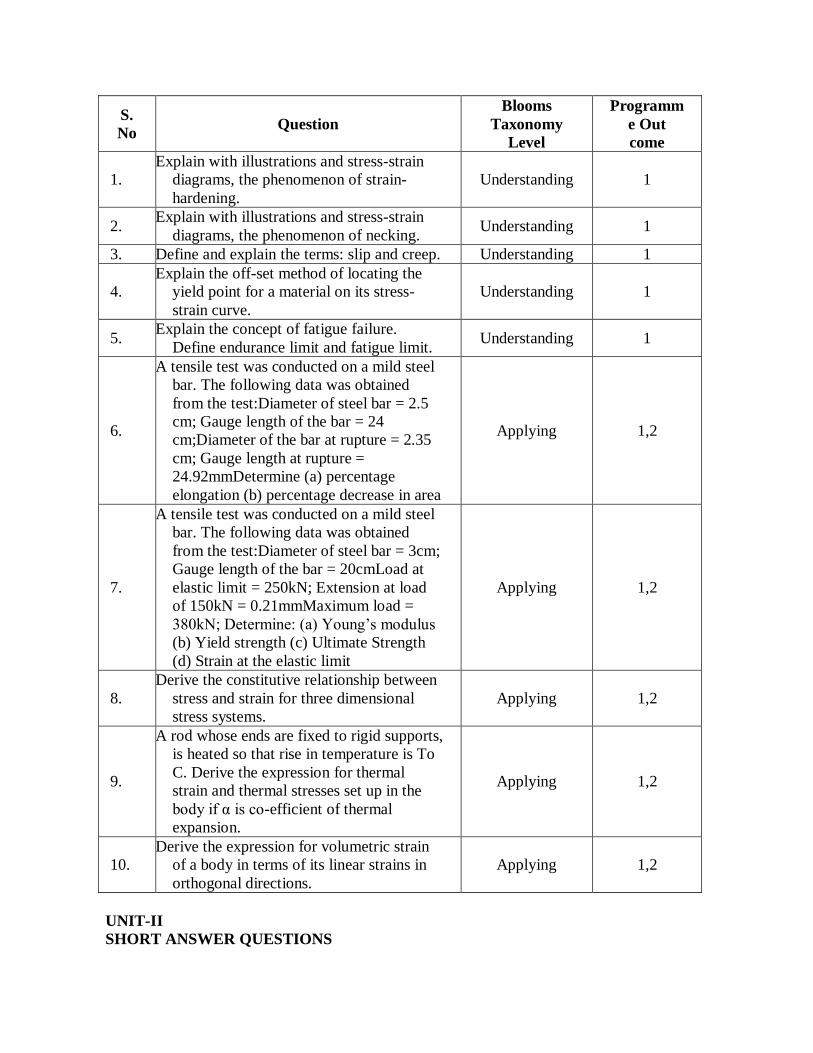
S.
No Question
Blooms
Taxonomy
Level
Programm
e Out
come
1.
Explain with illustrations and stress-strain
diagrams, the phenomenon of strain-
hardening.
Understanding 1
2. Explain with illustrations and stress-strain
diagrams, the phenomenon of necking. Understanding 1
3. Define and explain the terms: slip and creep. Understanding 1
4.
Explain the off-set method of locating the
yield point for a material on its stress-
strain curve.
Understanding 1
5. Explain the concept of fatigue failure.
Define endurance limit and fatigue limit. Understanding 1
6.
A tensile test was conducted on a mild steel
bar. The following data was obtained
from the test:Diameter of steel bar = 2.5
cm; Gauge length of the bar = 24
cm;Diameter of the bar at rupture = 2.35
cm; Gauge length at rupture =
24.92mmDetermine (a) percentage
elongation (b) percentage decrease in area
Applying 1,2
7.
A tensile test was conducted on a mild steel
bar. The following data was obtained
from the test:Diameter of steel bar = 3cm;
Gauge length of the bar = 20cmLoad at
elastic limit = 250kN; Extension at load
of 150kN = 0.21mmMaximum load =
380kN; Determine: (a) Young’s modulus
(b) Yield strength (c) Ultimate Strength
(d) Strain at the elastic limit
Applying 1,2
8.
Derive the constitutive relationship between
stress and strain for three dimensional
stress systems.
Applying 1,2
9.
A rod whose ends are fixed to rigid supports,
is heated so that rise in temperature is To
C. Derive the expression for thermal
strain and thermal stresses set up in the
body if α is co-efficient of thermal
expansion.
Applying 1,2
10. Derive the expression for volumetric strain
of a body in terms of its linear strains in
orthogonal directions.
Applying 1,2
UNIT-II
SHORT ANSWER QUESTIONS
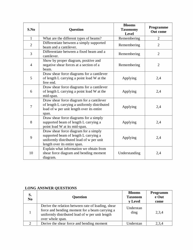
S.No Question
Blooms
Taxonomy
Level
Programme
Out come
1 What are the different types of beams? Remembering 2
2 Differentiate between a simply supported
beam and a cantilever. Remembering 2
3 Differentiate between a fixed beam and a
cantilever. Remembering 2
4
Show by proper diagram, positive and
negative shear forces at a section of a
beam.
Remembering 2
5
Draw shear force diagrams for a cantilever
of length L carrying a point load W at the
free end.
Applying 2,4
6
Draw shear force diagrams for a cantilever
of length L carrying a point load W at the
mid-span.
Applying 2,4
7
Draw shear force diagram for a cantilever
of length L carrying a uniformly distributed
load of w per unit length over its entire
span.
Applying 2,4
8
Draw shear force diagrams for a simply
supported beam of length L carrying a
point load W at its mid-span.
Applying 2,4
9
Draw shear force diagram for a simply
supported beam of length L carrying a
uniformly distributed load of w per unit
length over its entire span.
Applying 2,4
10
Explain what information we obtain from
shear force diagram and bending moment
diagram.
Understanding 2,4
LONG ANSWER QUESTIONS
S.
No Question
Blooms
Taxonom
y Level
Programm
e Out
come
1
Derive the relation between rate of loading, shear
force and bending moment for a beam carrying a
uniformly distributed load of w per unit length
over whole span.
Understan
ding
2,3,4
2 Derive the shear force and bending moment Understan 2,3,4
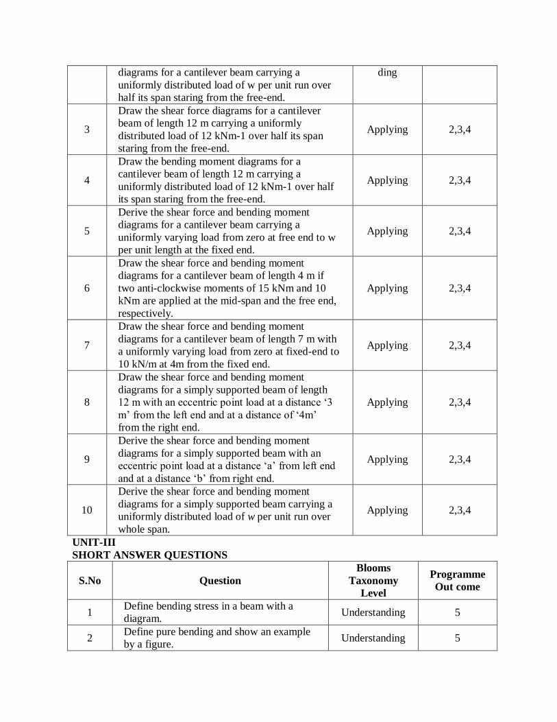
diagrams for a cantilever beam carrying a
uniformly distributed load of w per unit run over
half its span staring from the free-end.
ding
3
Draw the shear force diagrams for a cantilever
beam of length 12 m carrying a uniformly
distributed load of 12 kNm-1 over half its span
staring from the free-end.
Applying 2,3,4
4
Draw the bending moment diagrams for a
cantilever beam of length 12 m carrying a
uniformly distributed load of 12 kNm-1 over half
its span staring from the free-end.
Applying 2,3,4
5
Derive the shear force and bending moment
diagrams for a cantilever beam carrying a
uniformly varying load from zero at free end to w
per unit length at the fixed end.
Applying 2,3,4
6
Draw the shear force and bending moment
diagrams for a cantilever beam of length 4 m if
two anti-clockwise moments of 15 kNm and 10
kNm are applied at the mid-span and the free end,
respectively.
Applying 2,3,4
7
Draw the shear force and bending moment
diagrams for a cantilever beam of length 7 m with
a uniformly varying load from zero at fixed-end to
10 kN/m at 4m from the fixed end.
Applying 2,3,4
8
Draw the shear force and bending moment
diagrams for a simply supported beam of length
12 m with an eccentric point load at a distance ‘3
m’ from the left end and at a distance of ‘4m’
from the right end.
Applying 2,3,4
9
Derive the shear force and bending moment
diagrams for a simply supported beam with an
eccentric point load at a distance ‘a’ from left end
and at a distance ‘b’ from right end.
Applying 2,3,4
10
Derive the shear force and bending moment
diagrams for a simply supported beam carrying a
uniformly distributed load of w per unit run over
whole span.
Applying 2,3,4
UNIT-III
SHORT ANSWER QUESTIONS
S.No Question
Blooms
Taxonomy
Level
Programme
Out come
1 Define bending stress in a beam with a
diagram. Understanding 5
2 Define pure bending and show an example
by a figure. Understanding 5

3 Define neutral axis and where is it located
in a beam. Understanding 5
4 What are the assumptions made in theory of
simple bending? Remembering 5
5 Write the bending equation, defining all the
terms in the equation Remembering 5
6 Explain the terms: moment of resistance
and section modulus Remembering 5,6
7 Explain the role of section modulus in
defining the strength of a section. Understanding 5,6
8 Write the section modulus for a solid
rectangular section. Applying 5,6
9 Write the section modulus for a hollow
rectangular section. Applying 5,6
10 Write the section modulus for a solid
circular section. Applying 5,6
LONG ANSWER QUESTIONS
S.
No Question
Blooms
Taxonom
y Level
Progra
mme
Out
come
1 Derive the bending equation for a beam. Understan
ding 5
2
For a given stress, compare the moments of
resistance of a beam of a square section, when placed
(i) with its two sides horizontal and (ii) with its
diagonal horizontal. Which is more suitable?
Understan
ding 5,6
3
Three beams have the same length, the same
allowable stress and the same bending moment. The
cross-section of the beams are a square, a rectangle
with depth twice the width and a circle. If all the
three beams have the same flexural resistance
capacity, then find the ratio of the weights of the
beams. Which beam is most economical?
Understan
ding 5,6
4
A rectangular beam 60 mm wide and 150 mm deep is
simply supported over a span of 6 m. If the beam is
subjected to central point load of 12 kN, find the
maximum bending stress induced in the beam
section.
Applying 5,6
5
A rectangular beam 300 mm deep is simply
supported over a span of 4 m. What uniformly
distributed load the beam may carry, if the bending
stress is not to exceed 120 MPa. Take I = 225 x 106
mm4 .
Applying 5,6
6 A cantilever beam is rectangular in section having 80 Applying 5,6
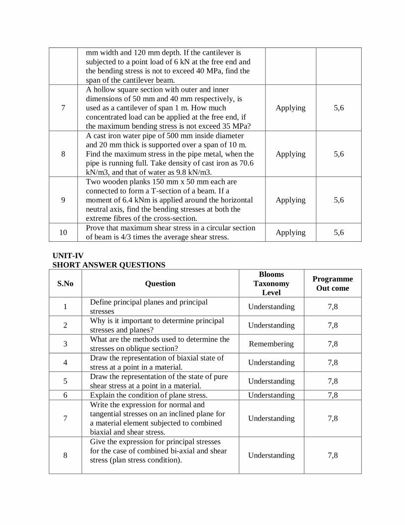
mm width and 120 mm depth. If the cantilever is
subjected to a point load of 6 kN at the free end and
the bending stress is not to exceed 40 MPa, find the
span of the cantilever beam.
7
A hollow square section with outer and inner
dimensions of 50 mm and 40 mm respectively, is
used as a cantilever of span 1 m. How much
concentrated load can be applied at the free end, if
the maximum bending stress is not exceed 35 MPa?
Applying 5,6
8
A cast iron water pipe of 500 mm inside diameter
and 20 mm thick is supported over a span of 10 m.
Find the maximum stress in the pipe metal, when the
pipe is running full. Take density of cast iron as 70.6
kN/m3, and that of water as 9.8 kN/m3.
Applying 5,6
9
Two wooden planks 150 mm x 50 mm each are
connected to form a T-section of a beam. If a
moment of 6.4 kNm is applied around the horizontal
neutral axis, find the bending stresses at both the
extreme fibres of the cross-section.
Applying 5,6
10 Prove that maximum shear stress in a circular section
of beam is 4/3 times the average shear stress. Applying 5,6
UNIT-IV
SHORT ANSWER QUESTIONS
S.No Question
Blooms
Taxonomy
Level
Programme
Out come
1 Define principal planes and principal
stresses Understanding 7,8
2 Why is it important to determine principal
stresses and planes? Understanding 7,8
3 What are the methods used to determine the
stresses on oblique section? Remembering 7,8
4 Draw the representation of biaxial state of
stress at a point in a material. Understanding 7,8
5 Draw the representation of the state of pure
shear stress at a point in a material. Understanding 7,8
6 Explain the condition of plane stress. Understanding 7,8
7
Write the expression for normal and
tangential stresses on an inclined plane for
a material element subjected to combined
biaxial and shear stress.
Understanding 7,8
8
Give the expression for principal stresses
for the case of combined bi-axial and shear
stress (plan stress condition).
Understanding 7,8
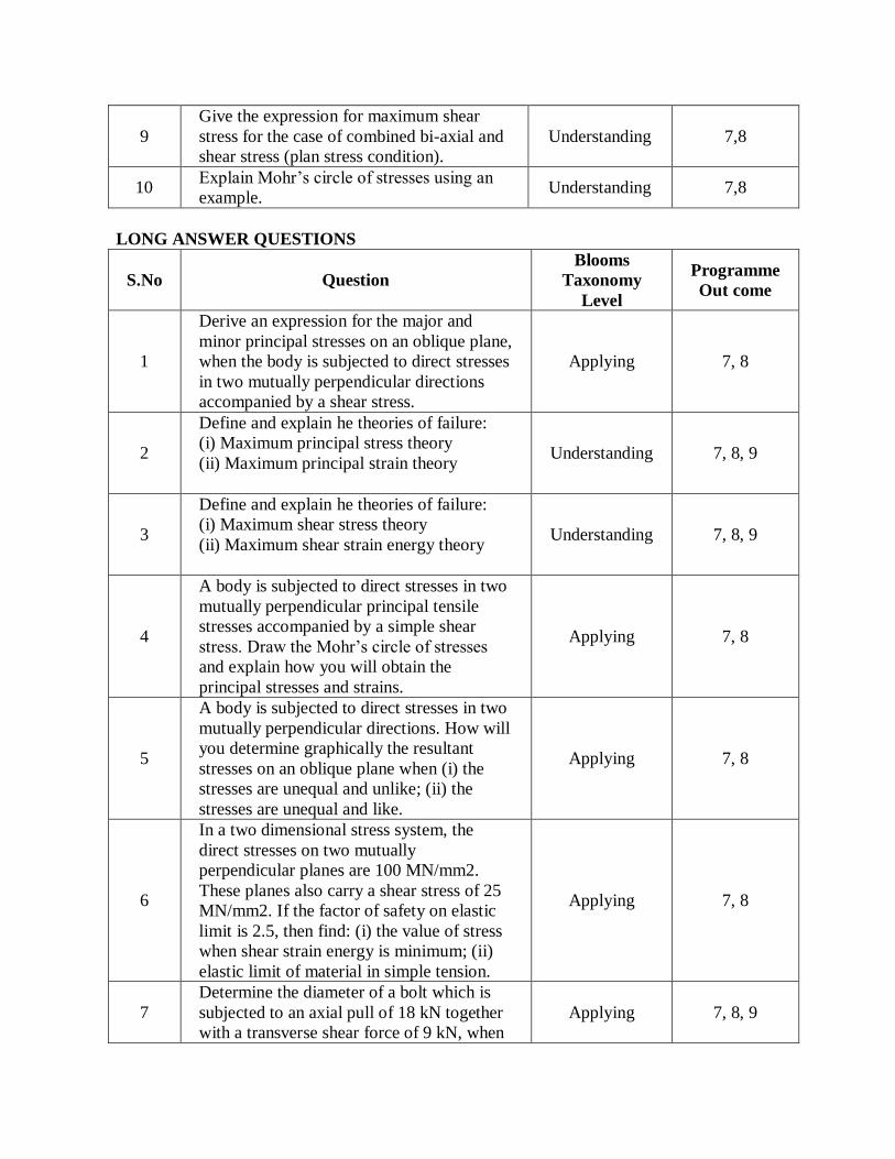
9
Give the expression for maximum shear
stress for the case of combined bi-axial and
shear stress (plan stress condition).
Understanding 7,8
10 Explain Mohr’s circle of stresses using an
example. Understanding 7,8
LONG ANSWER QUESTIONS
S.No Question
Blooms
Taxonomy
Level
Programme
Out come
1
Derive an expression for the major and
minor principal stresses on an oblique plane,
when the body is subjected to direct stresses
in two mutually perpendicular directions
accompanied by a shear stress.
Applying 7, 8
2
Define and explain he theories of failure:
(i) Maximum principal stress theory
(ii) Maximum principal strain theory
Understanding 7, 8, 9
3
Define and explain he theories of failure:
(i) Maximum shear stress theory
(ii) Maximum shear strain energy theory
Understanding 7, 8, 9
4
A body is subjected to direct stresses in two
mutually perpendicular principal tensile
stresses accompanied by a simple shear
stress. Draw the Mohr’s circle of stresses
and explain how you will obtain the
principal stresses and strains.
Applying 7, 8
5
A body is subjected to direct stresses in two
mutually perpendicular directions. How will
you determine graphically the resultant
stresses on an oblique plane when (i) the
stresses are unequal and unlike; (ii) the
stresses are unequal and like.
Applying 7, 8
6
In a two dimensional stress system, the
direct stresses on two mutually
perpendicular planes are 100 MN/mm2.
These planes also carry a shear stress of 25
MN/mm2. If the factor of safety on elastic
limit is 2.5, then find: (i) the value of stress
when shear strain energy is minimum; (ii)
elastic limit of material in simple tension.
Applying 7, 8
7
Determine the diameter of a bolt which is
subjected to an axial pull of 18 kN together
with a transverse shear force of 9 kN, when
Applying 7, 8, 9

the elastic limit in tension is 350 N/mm2,
factor of safety = 3 and μ = 0.3 using
(i) Maximum principal stress theory
(ii) Maximum principal strain theory
(iii) Maximum shear stress theory
(iv) Maximum strain energy theorem
(v) Maximum shear strain energy theory
8
A bolt is under an axial thrust of 10 kN
together with a transverse shear force of 4
kN. Calculate the diameter of bolt according
to
(i) Maximum principal stress theory
(ii) Maximum shear stress theory
(iii) Maximum strain energy theorem
Take elastic limit in simple tension = 225
N/mm2, factor of safety = 3, μ = 0.3.
Applying 7, 8, 9
10
The principal stresses at a point in a elastic
material are 30 N/mm2 (tensile), 120
N/mm2 (tensile) and 50 N/mm2
(compressive). If the elastic limit in
simpletension is 250 N/mm2 and μ = 0.3,
then determine whether the failure of
material will occur or not according to
(iii) Maximum principal stress theory
(iv) Maximum principal strain theory
(v) Maximum shear stress theory
(vi) Maximum strain energy theorem
(vii) Maximum shear strain energy theory
Applying 7, 8, 9
UNIT-V
SHORT ANSWER QUESTIONS
S.No Question
Blooms
Taxonomy
Level
Programme
Out come
1 Define deflection and slope of a beam. Remembering 10
2 Write the differential equation for the beam Remembering 10
3 List the different methods for finding slope
and deflection of a beam. Remembering 10

4 Explain the concept of double-integration
method to obtain the deflections of a beam Understanding 10
5
Give the relation between the load, shear
force and bending moment at a section of a
beam.
Remembering 10
6
What is Macaulay’s method? How is it
different from the general double
integration method?
Understanding 10
7 What is meant by flexural rigidity? Give its
expression. Remembering 10
8
Give the slope and deflection of a
cantilever beam, with flexural rigidity EI,
and length L, carrying a point load W at its
free end?
Remembering 10
9
Give the slope and deflection of a simply
supported beam, with flexural rigidity EI,
and length L, carrying a point load W at its
mid-span?
Remembering 10
10 State and explain the first theorem of Mohr. Understanding 10
LONG ANSWER QUESTIONS
S.No Question
Blooms
Taxonomy
Level
Programme
Out come
1
Derive an expression for slope and
deflection of a beam subjected to uniform
bending moment.
Applying 10
2
Prove that the relation where M is the
bending moment and E is modulus of
elasticity and I is moment of inertia of the
beam section.
Applying 10
3
Prove that the deflection at centre of a
simply supported beam, carrying a point
load at centre, is given by
Applying 10
4
Derive the slope at supports and deflection
at centre for a simply supported beam
carrying uniformly distributed load of w per
unit length over the entire span.
Applying 10
5
Use Moment-Area method to find the slope
and deflection of a simply supported beam
carrying a point load at the centre.
Applying 10
6
Use Moment-Area method to find the slope
and deflection of a simply supported beam
carrying a uniformly distributed load over
the entire span.
Applying 10
7 Derive slope and deflection of a cantilever Applying 10
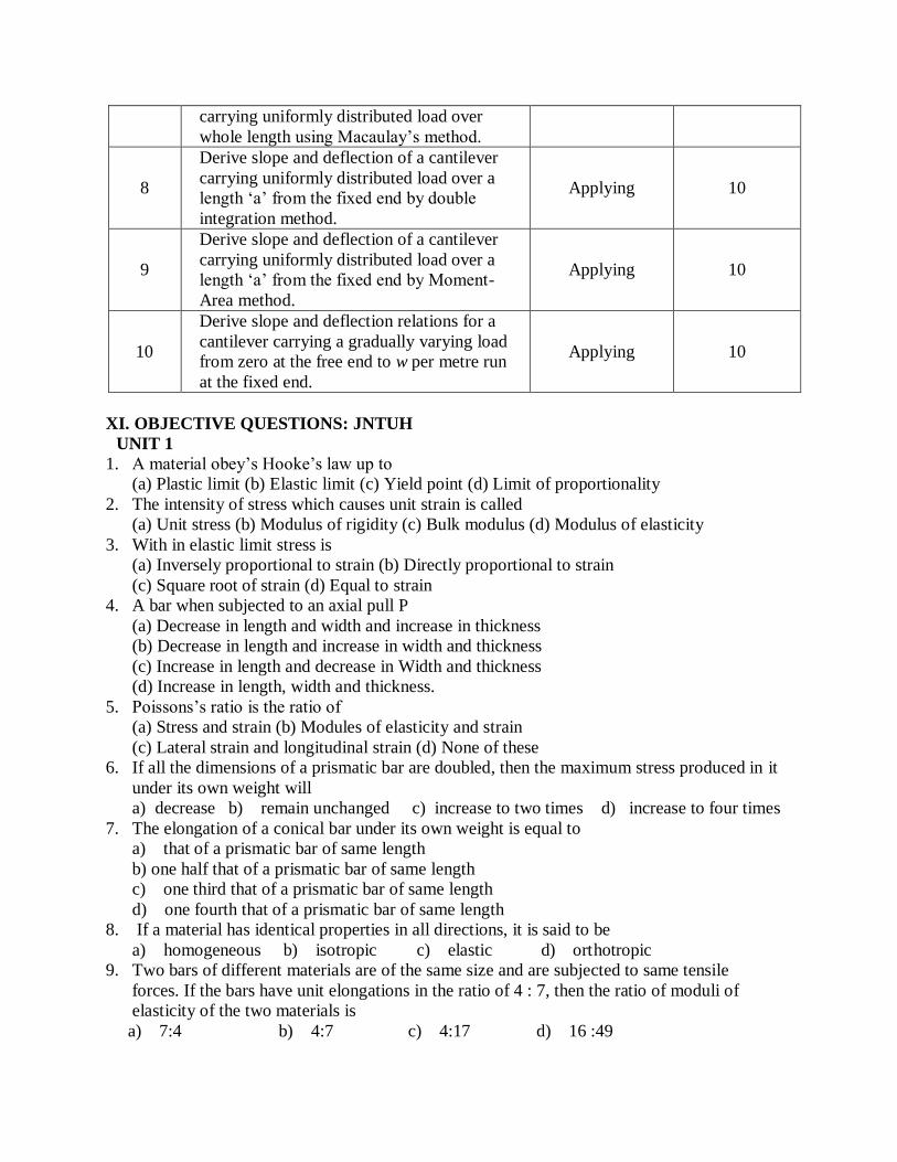
carrying uniformly distributed load over
whole length using Macaulay’s method.
8
Derive slope and deflection of a cantilever
carrying uniformly distributed load over a
length ‘a’ from the fixed end by double
integration method.
Applying 10
9
Derive slope and deflection of a cantilever
carrying uniformly distributed load over a
length ‘a’ from the fixed end by Moment-
Area method.
Applying 10
10
Derive slope and deflection relations for a
cantilever carrying a gradually varying load
from zero at the free end to w per metre run
at the fixed end.
Applying 10
XI. OBJECTIVE QUESTIONS: JNTUH
UNIT 1
1. A material obey’s Hooke’s law up to
(a) Plastic limit (b) Elastic limit (c) Yield point (d) Limit of proportionality
2. The intensity of stress which causes unit strain is called
(a) Unit stress (b) Modulus of rigidity (c) Bulk modulus (d) Modulus of elasticity
3. With in elastic limit stress is
(a) Inversely proportional to strain (b) Directly proportional to strain
(c) Square root of strain (d) Equal to strain
4. A bar when subjected to an axial pull P
(a) Decrease in length and width and increase in thickness
(b) Decrease in length and increase in width and thickness
(c) Increase in length and decrease in Width and thickness
(d) Increase in length, width and thickness.
5. Poissons’s ratio is the ratio of
(a) Stress and strain (b) Modules of elasticity and strain
(c) Lateral strain and longitudinal strain (d) None of these
6. If all the dimensions of a prismatic bar are doubled, then the maximum stress produced in it
under its own weight will
a) decrease b) remain unchanged c) increase to two times d) increase to four times
7. The elongation of a conical bar under its own weight is equal to
a) that of a prismatic bar of same length
b) one half that of a prismatic bar of same length
c) one third that of a prismatic bar of same length
d) one fourth that of a prismatic bar of same length
8. If a material has identical properties in all directions, it is said to be
a) homogeneous b) isotropic c) elastic d) orthotropic
9. Two bars of different materials are of the same size and are subjected to same tensile
forces. If the bars have unit elongations in the ratio of 4 : 7, then the ratio of moduli of
elasticity of the two materials is
a) 7:4 b) 4:7 c) 4:17 d) 16 :49
10. If a composite bar of steel and copper is heated, then the copper bar will be under
a) tension b) compression c) shear d) torsion
UNIT 2
1. The shape of cantilever for uniformly distributed load will be
(a) Straight line (b) Parabolic (c) Parabolic (d) Elliptical
2. A point of contraflexure occurs in a
(a) Simply supported beam (b) Fixed beam (c) Cantilever (d) None of the above
3. Shear force diagram for a cantilever beam carrying a uniformly distributed load over its
length is a
(a) Triangle (b) Rectangle (c) Hyperbola (d) Parabola
4. Maximum bending moment in a beam occurs where
a) deflection is zero b) shear force is maximum
c) shear force is minimum d) shear force changes sign
5. Rate of change of bending moment is equal to
a) shear force b) deflection c) slope d) rate of loading
6. The diagram showing the variation of axial load along the span is called
a) shear force diagram b) bending moment diagram
c) thrust diagram d) influence line diagram
7. The variation of the bending moment in the portion of a beam carrying linearly varying load
is a) linear b) parabolic c) cubic d) constant
8. The maximum bending moment due to a moving load on a fixed ended beam occurs
a) at a support b) always at the midspan
c) under the load only d) none of the above
UNIT 3
1. In I-section, the bending moment is resisted mainly by
(a) Flanges only (b) Web only (c) Both by flanges and web (d) None of the above
2. The ‘plane section remains plane’ assumption in bending theory implies:
(a) strain profile is linear (b) stress profile is linear
(c) both strain and stress profiles are linear (d) shear deformations are neglected
3. Beams of uniform strength are better as comapred to beams of uniform cross section as
they are Economical
(a) For short spans (b) For large spans
c) For heavy weight beams (d) For light weight beams
4. The square root of the ratio of moment of inertia of the cross section to its cross sectional
area is called
a)Second moment of area b)Slenderness ratio
c)Section modulus d)Radius of gyration
5. In T-section
(a) Both flange and web resists in the ratio of the their areas of cross-section
(b) Only flanges resists shear (c) Most of the shear is resisted by web only
(d) None of these
6. Shear stress in a rectangular beam exhibits a
(a) Parabolic variation (b) Linear variation (c) Cubic variation (d) None of the above
7. A beam of rectangular cross-section is 100 mm wide and 200 mm deep. If the section is
subjected to a shear force of 20 kN, then the maximum shear stress in the section is
a) 1 N/mm2 b) 1.125 N/mm2 c) 1.33 N/mm2 d) 1.5 N/mm2
8. A prismatic bar when subjected to pure bending assumes the shape of
a) catenary b) cubic parabola c) quadratic parabola d) arc of a circle
UNIT 4
1. Slope and deflection at a point in a loaded cantilever beam carrying several loads can be
found out by the
(a) Principle of least work (b) Moment area method
(c) Double integration method (d) Macualay’s method
2. If the depth of a rectangular beam is halved the deflection for a beam carrying a mid point
load shall be
(a) Halved (b) Doubled (c) Four times (d) Eight times
3. A cantilever of length L, carries a point load W at the free end. The downward deflection at
the free end is given by ________.
4. A cantilever of length L, carries a point load W at the free end. The slope at the free end is
given by ________.
5. A cantilever of length L, carries a udl w per unit length over the whole length. The
downward deflection at the free end is given by ________.
UNIT 5
1. Principal planes are planes having
(a) Maximum shear stress (b) No shear stress
(c) Minimum shear stress (d) None of the above
2. At the principal planes
(a) Normal stress is maximum or minimum and the shear stress is zero
(b) Tensile and compressive stresses are zero
(c) Tensile stress is zero and the shear stress is maximum.
(d) No stress acts
3. Mohr’s circle can be used to determine following stress on inclined surface
(a) Principal stress (b) Normal stress
(c) Tangential stress (d) Maximum shear stress (e) All of the above
4. The radius of Mohr's circle for two equal unlike principal stresses of magnitude p is
a) p b) p/2 c) zero d) none of these
5. Shear stress on principal planes is
a) zero b) maximum c) minimum d) none of these
6. The major and minor principal stresses at a point are 3MPa and -3MPa respectively. The
maximum shear stress at the point is a) Zero b)3MPa c)6MPa d)9MPa
7. The plane which have no shear stress are known as _______.
8. The stresses acting on principal planes are known as _________.
9. When a member is subjected to a simple shear stress, then the normal stress on an oblique
plane is given as ________.
10. When a member is subjected to a simple shear stress, then the tangential stress on an
oblique plane is given as ________.
XII. GATE QUESTIONS: 1. The shape of cantilever for uniformly distributed load will be
(a) Straight line (b) Parabolic (c) Parabolic (d) Elliptical
2. A point of contraflexure occurs in a
(a) Simply supported beam (b) Fixed beam
(c) Cantilever (d) None of the above

3. Shear force diagram for a cantilever beam carrying a uniformly distributed load over its
length is a
(a) Triangle (b) Rectangle (c) Hyperbola (d) Parabola
4. Maximum bending moment in a beam occurs where
a) deflection is zero b) shear force is maximum
c) shear force is minimum d) shear force changes sign
5. Rate of change of bending moment is equal to
a) shear force b) deflection c) slope d) rate of loading
6. The diagram showing the variation of axial load along the span is called
a) shear force diagram b) bending moment diagram
c) thrust diagram d) influence line diagram
7. The variation of the bending moment in the portion of a beam carrying linearly varying load
is a) linear b) parabolic c) cubic d) constant
8. The maximum bending moment due to a moving load on a fixed ended beam occurs
a) at a support b) always at the midspan
c) under the load only d) none of the above
9. A cantilever beam AB of length 1 carries a concentrated load W at its midspan C. If the free
end B is supported on a rigid prop, then there is a point of contraflexure
a) between A and C b) between C and B
c) one between A and C and other between C and B d) no where in the beam
10. A prismatic beam fixed at both ends carries a uniformly distributed load. The ratio of
bending moment at the supports to the bending moment at mid-span is
a) 0.5 b) 1.0 c) 1.5 d) 2.0
A beam of overall length 1 with equal overhangs on both sides carries a uniformly
distributed load over the entire length. To have numerically equal bending moments at
XIII. WEBSITES:
1. http://www.asce.org
2. http://www.icivilengineer.com
3. http://www.construction-guide.in
XIV. EXPERT DETAILS:
Prof. SATISH C . SHARMA Department of Mechanical & Industrial Engineering
Indian Institute of Technology Roorkee
Prof.M.S.Sivakumar Department of Applied Mechanics , IIT Madras.
email: [email protected]
Prof. S.K. Bhattacharyya, Department of Civil Engineering, IIT Kharagpur.
Dr. Satish C Sharma (IITR)
LS Ramachandra & SK Barai (IITKGP)
XV. JOURNALS:
0970-1141 Thesis Digest on civil Engineering 1987
0973-8061 International Engineering and Technology Journal
of Civil and Structure
2007
0975-5314 International journal of civil engineering 2009
0975-6744 Journal of information knowledge and research in
civil engineering
2009
0976-6308 International journal of civil engineering and
technology
2010

2249-426X International Journal of Civil Engineering and
Applications
2011
2249-8753 Recent Trends in Civil Engineering and
Technology
2011
2277-5986 World Research Journal of Civil Engineering 2011
2277-7032 International Journal of Structural and Civil
Engineering
2012
2278-9987 International Journal of Civil Engineering (IJCE) 2012
2319-6009 International Journal of Structural and Civil
Engineering Research
2012
2320-723X International Journal of Advanced Research in
Civil, Structural, Environmental and Infrastructure
Engineering and Developing
2013
XVI. LIST OF TOPICS FOR STUDENT SEMINARS:
1. Stresses and strain
2. Types of beam
3. Bending stress and shear stress
4. Mohr’s circle
5. Principle stresses and strain
6. Slope and Deflection of beam
7. Concept of Bending Equation
8. Important role of Strength of Materials
XVII. CASE STUDIES / SMALL PROJECTS:
1. The length of a broad -gauge railway sleeper such that it has the minimum bending
moment.