Strain Gage Instrumentation - assets.thermofisher.com
70
Strain Gage Instrumentation Micro-Measurements Stress Analysis Testing Structural Testing Materials Testing Data Book VMM-DB0107-1106 www.micro-measurements.com INTERACTIVE Click on the VPG logo on any datasheet to go to the contents page for that section. Click on the VPG logo on any contents page to go to the main table of contents page.
Transcript of Strain Gage Instrumentation - assets.thermofisher.com

Strain Gage Instrumentation Micro-Measurements
Stress Analysis TestingStructural TestingMaterials Testing
Data BookVMM-DB0107-1106
www.micro-measurements.com
INTERACTIVE
Click on the VPG logo on any datasheet to go to the contents page for that section.
Click on the VPG logo on any contents page to go to the main table of contents page.

Worldwide Contacts
www.vishaypg.comWhere the World Goes for Precision Measurement and Control
www.micro-measurements.com
The AmericasUnited States Vishay Precision Group – Micro-Measurements
P.O. Box 27777 • Raleigh, NC 27611Ph: +1-919-365-3800 • Fax: +1-919-365-3945E-mail: [email protected]
AsiaP.R. China Vishay Precision Group – Micro-Measurements
A8220, Shanghai Jia Hua Business Center No. 808 Hong Qiao Road • Shanghai 200030Ph: +86-21-6448-6090, Ext. 6098 • Fax: +86-21-6448-6070E-mail: [email protected]
EuropeFrance Vishay Precision Group – Micro-Measurements
16 Rue Francis Vovelle • 28000 Chartres Ph: +33-2-37-33-31-20 • Fax: +33-2-37-33-31-29E-mail: [email protected]
Germany Vishay Precision Group – Micro-MeasurementsTatschenweg 1 • 74078 HeilbronnPh: +49-7131-39099-0 • Fax +49-7131-39099-229E-mail: [email protected]
Spain Vishay Precision Group – Micro-MeasurementsC/Copenhague, N°4, 6 y 8 - Planta 1a - Oficina 12 • Edificio Al AndalusPolígono Európolis • 28232 Las Rozas, MadridPh: +34-916-407-624 • Fax: +34-916-375-601E-mail: [email protected]
United Kingdom Vishay Precision Group – Micro-MeasurementsStroudley Road • Basingstoke • Hampshire RG24 8FWPh: +44-(0)125-646-2131 • Fax: +44-(0)125-647-1441E-mail: [email protected]

Strain Gage Instrumentation
Vishay Precision GroupMicro-Measurements
P.O. Box 27777Raleigh, NC 27611
U.S.A.Phone: +1-919-365-3800
Fax: +1-919-365-3945www.micro-measurements.com

Disclaimer
ALL PRODUCTS, PRODUCT SPECIFICATIONS AND DATA ARE SUBJECT TO CHANGE WITHOUT NOTICE.
Vishay Precision Group, Inc., its affiliates, agents, and employees, and all persons acting on its or their behalf (collectively, “Vishay Precision Group”), disclaim any and all liability for any errors, inaccuracies or incompleteness contained herein or in any other disclosure relating to any product.
The product specifications do not expand or otherwise modify Vishay Precision Group’s terms and conditions of purchase, including but not limited to, the warranty expressed therein.
Vishay Precision Group makes no warranty, representation or guarantee other than as set forth in the terms and conditions of purchase. To the maximum extent permitted by applicable law, Vishay Precision Group disclaims (i) any and all liability arising out of the application or use of any product, (ii) any and all liability, including without limitation special, consequential or incidental damages, and (iii) any and all implied warranties, including warranties of fitness for particular purpose, non-infringement and merchantability.
Information provided in datasheets and/or specifications may vary from actual results in different applications and performance may vary over time. Statements regarding the suitability of products for certain types of applications are based on Vishay Precision Group’s knowledge of typical requirements that are often placed on Vishay Precision Group products. It is the customer’s responsibility to validate that a particular product with the properties described in the product specification is suitable for use in a particular application.
No license, express, implied, or otherwise, to any intellectual property rights is granted by this document, or by any conduct of Vishay Precision Group.
The products shown herein are not designed for use in life-saving or life-sustaining applications unless otherwise expressly indicated. Customers using or selling Vishay Precision Group products not expressly indicated for use in such applications do so entirely at their own risk and agree to fully indemnify Vishay Precision Group for any damages arising or resulting from such use or sale. Please contact authorized Vishay Precision Group personnel to obtain written terms and conditions regarding products designed for such applications.
Product names and markings noted herein may be trademarks of their respective owners.

For technical questions, [email protected]
Micro-Measurements
Revision: 18-May-2010www.micro-measurements.com
1
Table of ContentsTable of Contents
Revision: 18-May-2010
Instrument Selection ........................................................................................................................................................... 2
Strain Indicators and Calibrators
P3 ........................................................................................................................................................................................ 6
D4 ........................................................................................................................................................................................ 9
1550A .................................................................................................................................................................................. 11
Model V/E-40 ...................................................................................................................................................................... 13
Signal Conditioning Amplifiers
A2 ........................................................................................................................................................................................ 16
2100 System ....................................................................................................................................................................... 20
2200 System ....................................................................................................................................................................... 24
2300 System ....................................................................................................................................................................... 28
Digital Data Systems
Software for Stress Analysis Testing ................................................................................................................................... 34
System 6000 ....................................................................................................................................................................... 41
System 7000 ....................................................................................................................................................................... 50
Special-Purpose Instruments
Model 1300 ......................................................................................................................................................................... 66
Model 700 ........................................................................................................................................................................... 68
RS-200 ................................................................................................................................................................................ 70
System 8000 ....................................................................................................................................................................... 57
System 9000 ....................................................................................................................................................................... 61

For technical questions, contact [email protected]
Micro-Measurements
www.micro-measurements.com2
The A2, 2100, 2200, and 2300 Systems accept low-level signals, and condition and amplify them into high-level outputs suitable for multiple channel, simultaneous, dynamic recording. All of these systems can be used in conjunction with a variety of recording devices.
DIGITAL DATA SYSTEMS
Depending on their design, digital data systems can be used for measurement of static, dynamic, or both kinds of signals. Micro-Measurements offers three digital data systems, each controlled with StrainSmart® software and other third-party software.
System 5000 is a complete test and measurement data system for stress analysis and structural materials testing. Each 5100B scanner provides fast static data acquisition and digitization of 20 channels of various inputs. System flexibility allows for mixing types of input cards within a scanner for various input types including strain gages, thermocouples, LVDTs, load cells, and other transducer high level inputs. The system can be built up to 1200 channels, utilizing 60 scanners. Scan rates of up to 100 samples per second are available for simultaneous reading of all sensor inputs.
System 6000 is used for dynamic signals with scanning rates up to 10,000 samples per second per channel and up to 1200 channels. System 6000 provides individual analog-to-digital conversion on each channel and simultaneous sampling data acquisition for all channels. Selectable, digital Finite Impulse Response (FIR) low-pass filtering is incorporated into each instrumentation channel to meet a variety of testing requirements. Custom filters are also available.
System 7000 is a high performance dynamic data acquisition instrument with measurement accuracy of ±0.05% of full scale. Each sensor card employs a 24-bit analog to digital converter enabling 0.5 microstrain resolution. Scan rates up to 2048 samples per second are available for simultaneous reading of all sensor inputs. A combination of analog and flexible Finite Impulse Response (FIR) filters are available to provide adequate anti-alias filtering at all scanning rates. Electronically selectable bridge completion resistors allow the user to choose between 120-, 350-, and 1000-ohm strain gages through software selection. System 7000 is capable of self-calibration with a removable calibration reference.
STRAIN INDICATORS AND CALIBRATORS
Basic instrumentation requirements call for stability, accuracy and high resolution when making measurements under static loading conditions, and particularly where measurements are to be taken over long periods of time. Micro-Measurements offers our Model P3 Strain Indicator and D4 Data Acquisition Conditioner to meet these demanding criteria.
The Model P3 Strain Indicator and Recorder is a portable, battery-operated instrument while our D4 is a USB-powered instrument that connects to a personal computer. Both are capable of simultaneously accepting four inputs from quarter-, half-, and full-bridge strain-gage circuits, including strain-gage-based transducers. A highly stable measurement circuit, regulated bridge excitation supply, and precisely settable gage factor enable measurements of ±0.1% accuracy and 1 microstrain resolution. The P3 can also be configured and operated directly from your PC with a separate software application included with each instrument. The D4 also has a separate software application and is programmable for custom applications.
SIGNAL CONDITIONING AMPLIFIERS
When signals are produced by dynamically applied loads at frequencies above 0.1 Hz, or are transients, measuring instrumentation requires adequate frequency response, and a wide amplifier gain range for output to the appropriate recording or display device. Such an instrument consists of an amplifier and signal conditioner with a built-in or shared power supply. Individual units are normally required for each channel when simultaneous recording or multiple channels are needed. With the output sent to a suitable display device, signal conditioning amplifiers can be used for making long-term measurements under static loading conditions, when maximum stability and accuracy are not primary considerations.
Instrument Selection
Considerations for Instrument Selection
Document No.: 11048Revision: 28-Apr-2011

For technical questions, [email protected]
Micro-Measurements
Document No.: 11048Revision: 28-Apr-2011
www.micro-measurements.com3
Instrument Selection
Considerations for Instrument Selection
STRAIN INDICATORS AND CALIBRATORS
Instrument Display Operation Bridge Excitation Input Power Multi-Channel Remarks
P3 Digital Manual, Direct-Reading 1.5 VDC Battery, USB,
or AC Adapter Selectable Portable, 4-Channel, 0.1% Accuracy
D4 Host PC PC Controlled via USB 1.5 VDC USB Selectable 4-Channel,
0.1% Accuracy
SIGNAL CONDITIONING AMPLIFIERS
Instrument Frequency Response(1) Output (±) Amplifier Gain Bridge
Excitation Input Power Remarks
A2 DC 110 kHz –3 dB 10V 125-2500 DC
0.0-10VDC
(AC optional)
General-Purpose Signal Conditioner with Digital Control
2100 DC 15 kHz –3 dB 10V at 100 mA
Continuously Variable 1–2100
DC 0.5-12V AC
High Performance Amplifier for
Simultaneous Dynamic Recording
2200
DC 50 kHz –0.5 dB
DC 100 kHz –3 dB
10V at 10 mA and
1 VRMS at 10 mA
Continuously Variable 1–3300
DC: 0.5-15V or 0.5-30 mA
ACHigh Performance,
for Demanding Environments
2300
DC 60 kHz –0.5 dB
DC 145 kHz –3 dB
10VContinuously
Variable 1–11,000
DC: 0.7-15V
(11 steps) 0.2-7V Variable
AC
High-Frequency Response
Multi-Feature Signal Conditioner
(1) Typical—see specific product bulletin and/or instruction manual for detailed performance specifications.
DIGITAL DATA SYSTEMS
Instrument Operating Mode(2) Channels Scanning
RateBridge
Excitation (3)Input
Power Remarks
5000 (5100)
Stationary, Online
5–1200 (in increments of 5)
1–100 Samples/Sec/
Channel
0-10 VDC Programmable AC 5-Hz
Low-Pass Filter
6000 (6100)
Stationary, Online 1–1200
10–10,000 Samples/Sec/
Channel
0-10 VDC Programmable AC
Programmable Digital Filters to
4 kHz
6000 (6200)
Remote, Stand-Alone 1–1200
10–10,000 Samples/Sec/
Channel
0-10 VDC Programmable
DC (AC Optional)
Programmable Digital Filters to
4 kHz
7000 Stationary, Online
Unlimited (in increments of 8)
10–2048 Samples/Sec/
Channel
0-10 VDC Programmable
DC (AC Optional)
Programmable Digital Filters to
800 Hz
(2) All systems can be operated with StrainSmart software for data acquisition, storage, reduction, and presentation, or with other third-party software.(3) Strain gage cards only.
Considerations for instrument selection are provided on the previous page for all general-purpose instrumentation and data systems produced by Micro-Measurements. Additionally, our Applications Engineering staff is always available to assist you in selecting the right instrument for your specific applications.
INSTRUMENT SELECTION GUIDE
Instrument Selection
Document No.: 11048Revision: 28-Apr-2011
For technical questions, [email protected]
www.micro-measurements.com5
Strain Indicatorsand Calibrators
P3 .......................................................... 6
D4 .......................................................... 9
1550A .................................................... 11
V/E-40 .................................................... 13

For technical questions, contact [email protected]
Micro-Measurements
www.micro-measurements.com6
FEATURES
• Four input channels• Direct reading LCD display• On-board data storage• 0 to 2.5 VDC analog output• Quarter-, half-, and full-bridge circuits• Built-in bridge completion• 120-, 350-, and 1000-ohm dummy gages• Automatic zero-balancing and calibration• Intuitive, menu-driven operations• USB data link• Operation from keypad or PC• Portable, lightweight, and rugged• Battery, USB, or line-voltage power• Optional 10-pin transducer connectors
DESCRIPTION The Model P3 Strain Indicator and Recorder is a portable, battery-operated instrument capable of simultaneously accepting four inputs from quarter-, half-, and full-bridge strain-gage circuits, including strain-gage-based transducers. Water-resistant grommets in the hinged cover allow the lid to be closed with leadwires attached. Designed for use in a wide variety of physical test and measurement applications, the P3 functions as bridge amplifier, static strain indicator, and digital data logger.
The Model P3 Strain Indicator and Recorder, utilizing a large LCD display for readout of setup information and acquired data, incorporates many unique operating features that make it the most advanced instrument of its kind. An extensive, easy-to-use menu-driven user interface operates through a front-panel keypad to readily configure the P3 to meet your particular measurement requirements. Selections include active input and output channels, bridge configuration, measurement units, bridge balance, calibration method, and recording options, among others.
Standard sensor input connection is via eccentric-lever-release terminal blocks. Optional transducer connection is available via side-mounted bayonet locking circular connectors.
Data, recorded at a user-selectable rate of up to 1 reading per channel per second, is stored on a removable flash card and is transferred by USB to a host computer for subsequent storage, reduction and presentation with the supplied software.
The P3 can also be configured and operated directly from your PC with a separate software application included with each instrument. Additionally, a full set of ActiveX components is provided for creating custom applications in any language supporting ActiveX.
A highly stable measurement circuit, regulated bridge excitation supply, and precisely settable gage factor enable measurements of ±0.1% accuracy and 1 microstrain resolution. Bridge completion resistors of 120, 350 and 1000 ohms are built in for quarter-bridge operation. Also, input connections and switches are provided for remote shunt calibration of transducers and full-bridge circuits.
The P3 operates from two readily available D cells. Battery life depends upon mode of operation but ranges up to 600 hours of continuous use for a single channel. It can also be powered by connection to an external battery or power supply, a USB port on a PC or with an optional external line-voltage adapter, the Model P3-A105.
Strain Indicator and Recorder
Document No.: 11102Revision: 06-May-2011
P3

For technical questions, [email protected]
Micro-Measurements
Document No.: 11102Revision: 06-May-2011
www.micro-measurements.com7
P3
Strain Indicator and Recorder
P3
Document No.: 11102Revision: 06-May-2011
HARDWARE SPECIFICATIONS
All specifications nominal or typical at +23°C unless noted.
Inputs Eccentric-lever-release terminal blocks accept up to four independent bridge inputs. Accommodates 16-28 AWG (1.3 to 0.35 mm diameter) wire.
The Transducer Option includes four 10-pin bayonet locking circular connectors mounted on the side of the case and wired in parallel to the lever-release terminal blocks. The supplied mating connector has a 0.046 inch (1.17 mm) diameter solder well.
Bridge Configurations Quarter-, half-, and full-bridge circuits. Internal bridge completion provided for 120Ω, 350Ω and 1000Ω quarter bridges, 60 to 2000Ω half or full bridge.
Display Full dot-matrix structure with 128 dots x 64 dots FSTN positive, gray transflective LCD with backlight. Display update is twice a second.
Data ConversionHigh-resolution sigma-delta converter. 60 Hz or 50 Hz noise rejection. User selectable.
Basic Range±31,000 microstrain (±1 microstrain resolution) at Gage Factor = 2.000
Accuracy±0.1% of reading ±3 counts. (Normal mode operation at Gage Factor = 2.000)
Gage Factor SettingsRange 0.500 to 9.900
BalanceSingle key operation to initiate automatic software balance
Bridge Excitation1.5 VDC nominal. Readings are fully ratiometric, and not degraded by variation in excitation voltage
Communication InterfaceUniversal Serial Bus with type B connector. Used for transferring stored data and firmware.
Data Storage
Media: Removable Secure Digital or Multimedia Card (2GB max). Data Recording Rate: 1 reading per second maximum.
CalibrationShunt calibration across each dummy resistor to simulate 5000 microstrain (±0.1%). Remote calibration supported via accessible switch contacts at input terminal block.
Analog OutputBNC connector. 0 to 2.5V maximum output. Device impedance of 2000Ω or greater. 480 samples/second DAC output update rate.
PowerInternal battery pack using two “D” cells. Battery life up to 600 hours (single channel, normal mode.) Can also be powered from USB or by external battery or other power source of 6 to 15 VDC. AC adapter optional (Model P3-A105).
Operational EnvironmentTemperature 0 to + 50°C. Humidity up to 90% RH, noncondensing

For technical questions, contact [email protected]
Micro-Measurements
www.micro-measurements.com8
P3
Document No.: 11102Revision: 06-May-2011
Strain Indicator and Recorder
FIRMWARE FEATURES
Display Update Rate2 readings per second
Recording RatesUp to 64 data filesAutomatic recording
1 reading every 1 to 3600 secondsIndividually selectable per channel
Manual recordingAutomatic date/time stamping
ScalingAutomatic scaling for microstrain, based upon gage factor, with nonlinearity correction based upon bridge typeAutomatic calculation of mV/VLinear scaling for other engineering units
Unitsμε g rpm hpmV/V lbf m degpsi lb s radksi kg A ozGPa in N mVMPa mm V m/s2
Pa mil Ohms ton Bridge TypesQuarter bridgeHalf bridge, adjacent arms, equal and opposite strainsHalf bridge opposite arms equal strainsShear bridge, 2 active armsPoisson half bridgeFull bridge 4 fully active armsShear bridge, 4 active armsFull bridge, Poisson gages in opposite armsFull bridge, Poisson gages in adjacent armsUndefined full bridgeUndefined half bridge/quarter bridge
Bridge BalanceAutomaticManual offset adjustDisabled (Raw offset)
Backlight ControlProgrammable on time while in run mode
5, 15 or 60 secondsManual off/on
If illuminated, backlight will remain illuminated while operating menus
Software Adjustable Contrast
Operating ModesNormal modeAnalog output (any one of four channels)
Data LinkUSB interfaceWindows-based P3 software provided for control and data storageNo device driver required (treated as an HID device)
Real-time Clock System Calibration/VerificationRequires Model 1550A Strain Indicator calibrator or other compatible calibrator Calibration date stored in flash memory
Firmware Upgradeable
View Showing Optional Transducer Input Connectors

For technical questions, [email protected]
Micro-Measurements
Document No.: 11257Revision: 23-May-2011
www.micro-measurements.com9
D4
FEATURES
• Four input channels with RJ-45 connectors • Hardware and software support for quarter-, half- and
full-bridge circuits• Built-in precision bridge completion for 120-, 350-, and
1000-ohm half and quarter bridges• 8-Hz sampling rate• Intuitive, user-friendly software communicates with up
to six D4 units simultaneously• Automatic and manual zero-balance and calibration• Full control of all functions via USB Interface• Portable, lightweight, and rugged design• Powered via USB interface• Programmable for custom applications
DESCRIPTION
The Model D4 Data Acquisition Conditioner is a portable, USB-powered precision instrument for use with resistive strain gages and strain gage-based transducers.
The Model D4 has four channels of data acquisition. Connection to each channel is via a RJ-45 connector. Each channel of input accepts either full-, half-, and quarter-bridge configuration. All required bridge completion components for 120-, 350-, and 1000-ohm bridges are supplied.
Operation of the Model D4 is performed with commands sent via the USB connection. User-friendly application software is provided to control the D4 with a MS Windows-based personal computer. The software connects with up to six D4 units to create a system of up to 24 channels. The D4 units can be connected directly to a computer through its USB ports or through a USB hub.
A Programmer’s Reference Kit that includes a Programmer’s Reference Manual, a NI LabVIEW instrument driver, and programming examples to simplify writing custom applications is also included. The D4 is also supplied with a calibration software utility that allows calibration of the D4 via the USB interface. The application software, Programmer’s Reference Kit, and Instruction Manual are on a single CD included with the D4 unit.
The Model D4 uses modern digital signal processing technology to provide excellent noise rejection and stability. Proprietary scaling and linearization algorithms provide unsurpassed measurement accuracy for strain gage bridge measurements.
SPECIFICATIONS
Note: Performance may be degraded at high levels of repetitive electrostatic discharge; however, no damage to the unit will occur.
INPUT CONNECTIONSType: RJ-45 ModularQuantity: Four
BRIDGE CONFIGURATIONSTypes: Quarter-, half-, and full bridgesBridge Impedance: 60 to 2000 ΩInternal Bridge Completion:
Quarter bridge: 120 Ω, 350 Ω and 1000 Ω ±0.01%Half bridge: 1000 Ω ±0.01%
DATA CONVERSIONA/D Converter: Delta-sigma with integral chopper-stabilized programmable gain instrumentation amplifierResolution: 24 bits. Noise-free resolution: 18 bits typ.Filter: Integrated linear phase FIR Sinc5 filter followed by a Sinc3 filter with a programmable decimation rate. Software selectable output rate provides >120 dB rejection of 50 or 60 Hz and higher level harmonics.
Front Panel Back Panel
D4
Data Acquisition Conditioner
Document No.: 11257Revision: 23-May-2011

For technical questions, contact [email protected]
Micro-Measurements
www.micro-measurements.com10
D4
Document No.: 11257Revision: 23-May-2011
Data Acquisition Conditioner
MEASUREMENT RANGE/RESOLUTIONStrain Range: ±31,000 με at GF = 2.000. (±15.5 mV/V)Resolution: ±1 με at GF = 2.000 (±0.0005 mV/V)
MEASUREMENT ACCURACY±0.1% of reading ±3 counts. (Instrument Gage Factor = 2.000)
GAGE FACTOR CONTROLRange: 0.500 to 9.900
BALANCE CONTROLType: SoftwareControl: Manual or automatic
BRIDGE EXCITATIONValue: 1.5 VDC nominal Control: Software enable/disableMeasurements are fully ratiometric, and not degraded by variations in excitation voltage
COMMUNICATION INTERFACEUniversal serial bus (USB). Cable included
SHUNT CALIBRATIONLocation: Across each quarter-bridge completion resistorControl: Software
Values: P– to D120: 11.94K Ω ±0.1% (5000 με at GF = 2.00)P– to D350: 34.8K Ω ±0.1% (5000 με at GF = 2.00)P– to D1000: 99.5K Ω ±0.1% (5000 με at GF = 2.00)
POWERUSB: 5 V 100 mA
OPERATIONAL ENVIRONMENTTemperature: 0° to +50°CHumidity: Up to 90% RH. Non-condensing.
CASE Material: Aluminum
SIZE AND WEIGHT Size: 4.3 W x 1.4 H x 5.7 L inches (110 x 36 x 145 mm) Weight: 0.8 lb. (0.36 kg)
ACCESSORIES
D4-A106 Shielded Connectors
D4-A108 Crimping Tool
D4-A116 USB Cable (Type A to Type B—6-foot length)

For technical questions, [email protected]
Micro-Measurements
Document No.: 11313Revision: 17-May-2011
www.micro-measurements.com11
1550A
FEATURES
• True Wheatstone bridge circuitry• Simulates quarter, half, and full bridge—both
120Ω/350Ω• Three decades of push buttons• Strain range direct reading: ±99 900 με. . .increments of
100 με• Transducer range: ±49.95 mV/V. . . increments of
0.05 mV/V• Reversing switch for plus and minus calibration• High precision resistors used throughout to ensure
excellent stability• Accuracy 0.025 percent—traceable to the U.S. National
Institute of Standards and Technology
DESCRIPTION Sound engineering and laboratory practices require that the instrumentation used to make critical strain measurements be periodically calibrated to verify that it is within the manufacturer’s original specifications. Additionally, each type of strain indicator exhibits some degree of nonlinearity, especially for large strains during quarter-bridge operation. Since this is the most common stress analysis application of strain gages, it is important that the strain indicator be calibrated in this mode. Instrumentation span should also be checked at a number of points before each important test to avoid inaccurate data.
The Model 1550A calibrator is a Wheatstone bridge and generates a true change of resistance in one or two arms of the bridge. It simulates the actual behavior of a strain gage in both positive and negative strain.
The ‘star network’ used in certain other commercial calibrators provides a substantially lower cost instrument design, because component specifications are less critical, and fewer components are required.
However, the ‘star network’ cannot simulate quarter-bridge strain gage behavior, and cannot simulate positive strain. Another serious problem with this circuit is that the bridge input and output resistances change in an abnormal manner, leading to inaccuracies in calibration under some conditions.
A calibrator based on the Wheatstone bridge principle requires stable components. A total of 66 ultra-stable precision resistors are used in the Model 1550A calibrator to provide the stability, repeatability, accuracy and incremental steps required in a laboratory standards instrument.
WHEATSTONE BRIDGE / STAR NETWORK
SPECIFICATIONS
ACCURACY 0.025% of setting ±1 με (0.0005 mV/V), maximumTraceable to United States National Institute of Standards and Technology
REPEATABILITY ±1 με (0.0005 mV/V), maximum
STABILITY (0.001% of setting ±1 με) /°C, maximum
THERMAL EMF0.5 μV/V of excitation, maximum
1550A
Strain Indicator Calibrator
Document No.: 11313Revision: 17-May-2011
A laboratory standard for verifying the calibration of strain and transducer indicators.
For technical questions, contact [email protected]
Micro-Measurements
www.micro-measurements.com12
1550A
Document No.: 11313Revision: 17-May-2011
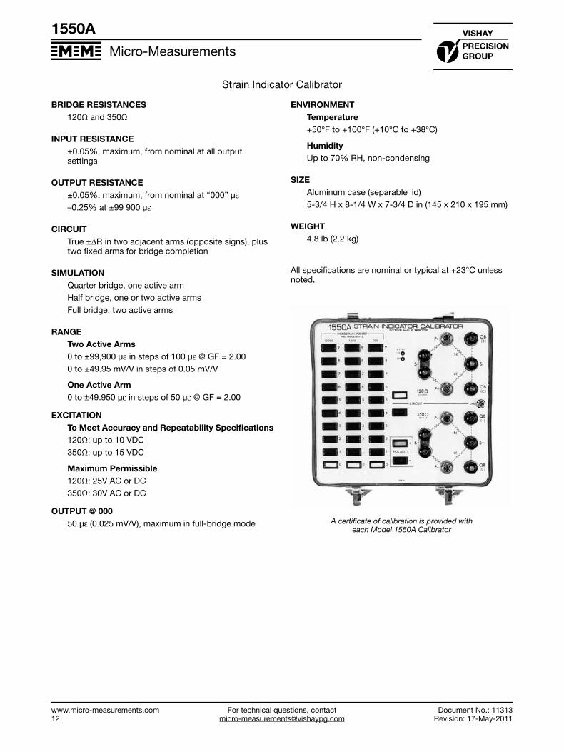
Strain Indicator Calibrator
BRIDGE RESISTANCES 120Ω and 350Ω
INPUT RESISTANCE ±0.05%, maximum, from nominal at all output settings
OUTPUT RESISTANCE ±0.05%, maximum, from nominal at “000” με–0.25% at ±99 900 με
CIRCUITTrue ±ΔR in two adjacent arms (opposite signs), plus two fixed arms for bridge completion
SIMULATION Quarter bridge, one active armHalf bridge, one or two active armsFull bridge, two active arms
RANGETwo Active Arms 0 to ±99,900 με in steps of 100 με @ GF = 2.000 to ±49.95 mV/V in steps of 0.05 mV/V
One Active Arm 0 to ±49.950 με in steps of 50 με @ GF = 2.00
EXCITATIONTo Meet Accuracy and Repeatability Specifications120Ω: up to 10 VDC350Ω: up to 15 VDC
Maximum Permissible 120Ω: 25V AC or DC350Ω: 30V AC or DC
OUTPUT @ 000 50 με (0.025 mV/V), maximum in full-bridge mode
ENVIRONMENT Temperature+50°F to +100°F (+10°C to +38°C)
HumidityUp to 70% RH, non-condensing
SIZE Aluminum case (separable lid) 5-3/4 H x 8-1/4 W x 7-3/4 D in (145 x 210 x 195 mm)
WEIGHT 4.8 lb (2.2 kg)
All specifications are nominal or typical at +23°C unless noted.
A certificate of calibration is provided with each Model 1550A Calibrator
For technical questions, [email protected]
Micro-Measurements
Document No.: 11316Revision: 17-May-2011
www.micro-measurements.com13
Model V/E-40
FEATURES
• 5 Decade selector switches• Resistance range: 30.00 to 1111.10Ω in 0.01Ω steps• High precision resistors used throughout to ensure
excellent stability• Accuracy 0.02% of setting• Simulates tension and compression strain for most
widely used strain gage resistance values• Simulates a broad range of RTDs for instrumentation
setup and calibration
DESCRIPTION
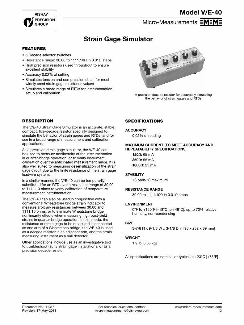
The V/E-40 Strain Gage Simulator is an accurate, stable, compact, five-decade resistor specially designed to simulate the behavior of strain gages and RTDs, and for use in a broad range of measurement and calibration applications.
As a precision strain gage simulator, the V/E-40 can be used to measure nonlinearity of the instrumentation in quarter-bridge operation, or to verify instrument calibration over the anticipated measurement range. It is also well suited to measuring desensitization of the strain gage circuit due to the finite resistance of the strain gage leadwire system.
In a similar manner, the V/E-40 can be temporarily substituted for an RTD over a resistance range of 30.00 to 1111.10 ohms to verify calibration of temperature measurement instrumentation.
The V/E-40 can also be used in conjunction with a conventional Wheatstone bridge strain indicator to measure arbitrary resistances between 30.00 and 1111.10 ohms, or to eliminate Wheatstone bridge nonlinearity effects when measuring high post-yield strains in quarter-bridge operation. In this mode, the resistance or strain gage to be measured is connected as one arm of a Wheatstone bridge, the V/E-40 is used as a decade resistor in an adjacent arm, and the strain measuring instrument as a null detector.
Other applications include use as an investigative tool to troubleshoot faulty strain gage installations, or as a precision decade resistor.
A precision decade resistor for accurately simulating the behavior of strain gages and RTDs
SPECIFICATIONS
ACCURACY0.02% of reading
MAXIMUM CURRENT (TO MEET ACCURACY AND REPEATABILITY SPECIFICATIONS)
120Ω: 65 mA350Ω: 55 mA1000Ω: 25 mA
STABILITY±3 ppm/°C maximum
RESISTANCE RANGE30.00 to 1111.10Ω in 0.01Ω steps
ENVIRONMENT0°F to +120°F [–18°C to +49°C], up to 70% relative humidity, non-condensing
SIZE3-7/8 H x 9-1/8 W x 3-1/8 D in [98 x 232 x 89 mm]
WEIGHT1.9 lb [0.85 kg]
All specifications are nominal or typical at +23°C [+73°F]
Model V/E-40
Strain Gage Simulator
Document No.: 11316Revision: 17-May-2011

For technical questions, [email protected]
www.micro-measurements.com15
Signal Conditioning
Amplifiers
A2 .......................................................... 16
2100....................................................... 20
2200....................................................... 24
2300....................................................... 28
For technical questions, contact [email protected]
Micro-Measurements
www.micro-measurements.com16
FEATURES
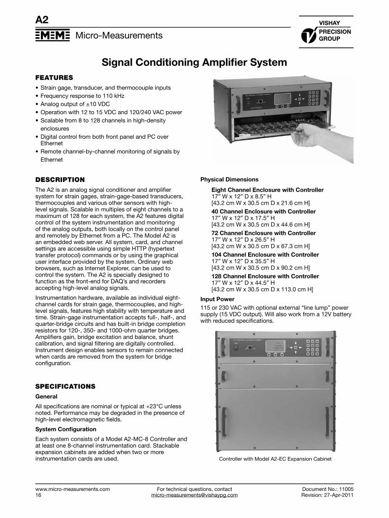
• Strain gage, transducer, and thermocouple inputs• Frequency response to 110 kHz• Analog output of ±10 VDC• Operation with 12 to 15 VDC and 120/240 VAC power• Scalable from 8 to 128 channels in high-density enclosures• Digital control from both front panel and PC over
Ethernet• Remote channel-by-channel monitoring of signals by Ethernet
DESCRIPTION
The A2 is an analog signal conditioner and amplifier system for strain gages, strain-gage-based transducers, thermocouples and various other sensors with high-level signals. Scalable in multiples of eight channels to a maximum of 128 for each system, the A2 features digital control of the system instrumentation and monitoring of the analog outputs, both locally on the control panel and remotely by Ethernet from a PC. The Model A2 is an embedded web server. All system, card, and channel settings are accessible using simple HTTP (hypertext transfer protocol) commands or by using the graphical user interface provided by the system. Ordinary web browsers, such as Internet Explorer, can be used to control the system. The A2 is specially designed to function as the front-end for DAQ’s and recorders accepting high-level analog signals.
Instrumentation hardware, available as individual eight-channel cards for strain gage, thermocouples, and high-level signals, features high stability with temperature and time. Strain-gage instrumentation accepts full-, half-, and quarter-bridge circuits and has built-in bridge completion resistors for 120-, 350- and 1000-ohm quarter bridges. Amplifiers gain, bridge excitation and balance, shunt calibration, and signal filtering are digitally controlled. Instrument design enables sensors to remain connected when cards are removed from the system for bridge configuration.
SPECIFICATIONS
General
All specifications are nominal or typical at +23°C unless noted. Performance may be degraded in the presence of high-level electromagnetic fields.
SystemConfiguration
Each system consists of a Model A2-MC-8 Controller and at least one 8-channel instrumentation card. Stackable expansion cabinets are added when two or more instrumentation cards are used.
PhysicalDimensions
EightChannelEnclosurewithController17″ W x 12″ D x 8.5″ H [43.2 cm W x 30.5 cm D x 21.6 cm H]40ChannelEnclosurewithController17″ W x 12″ D x 17.5″ H [43.2 cm W x 30.5 cm D x 44.6 cm H]72ChannelEnclosurewithController17″ W x 12″ D x 26.5″ H [43.2 cm W x 30.5 cm D x 67.3 cm H]104ChannelEnclosurewithController17″ W x 12″ D x 35.5″ H [43.2 cm W x 30.5 cm D x 90.2 cm H]128ChannelEnclosurewithController17″ W x 12″ D x 44.5″ H [43.2 cm W x 30.5 cm D x 113.0 cm H]
InputPower115 or 230 VAC with optional external “line lump” power supply (15 VDC output). Will also work from a 12V battery with reduced specifications.
A2
SignalConditioningAmplifierSystem
Document No.: 11005Revision: 27-Apr-2011
Controller with Model A2-EC Expansion Cabinet

For technical questions, [email protected]
Micro-Measurements
Document No.: 11005Revision: 27-Apr-2011
www.micro-measurements.com17
A2
Signal Conditioning Amplifier System
MODEL A2-MC-8 CONTROLLER
Supports hardware identification, setup and output data monitoring of each type of plug-in card via a local keyboard interface or remotely via an Ethernet Interface. Each controller supports 8 channels of signal conditioning and up to 128 channels of signal conditioning when expansion cabinets are added.
FrontPanelUserInterfaceMembrane keypad with illuminated 128 x 64 pixel FSTN positive, gray transflective LCD
CommunicationInterfacePhysical: 10/100 Base-T Protocol: HTTP IP Addressing: Static. Configurable by the front panel controls
Size17″ W X 12″ D X 8.5″H [43.2 cm W x 30.5 cm D x 21.6 cm H]
Weight12.6 lbs [5.7 kg]
MODEL A2-SG-8-BX STRAIN GAGE CARD
(Specify ModelA2-SG-8-BW (with Butterworth filter characteristics) or ModelA2-SG-8-BS (with Bessel filter characteristics).
These specifications apply for each of eight independent channels of signal conditioning per removable card.
AmpInput
InputsQuarter (120 ohms, 350 ohms, and 1000 ohms), half and full bridge (50-1000 ohms) Bridge completion resistors are provided for quarterbridge circuitsInputImpedance>100 MΩ
SourceCurrent±5 nA typical; ±10 nA max.
Amplifier
ZeroTemperatureStability±1.7 µV/°C RTI*, ±100 µV/°C RTO**, after 30-minute warm-upInputRange4 to 80 mV full-scale input range (x2500 to x125)— adjustable by software control per channelOutputRange±10V into 600Ω minimum load (When powered from 15 VDC)DCGainAccuracyandStability±0.10%; ±50 ppm/°CCommon-ModeRejection(DCto100Hz)105 dB typicalCommon-ModeVoltage±10V typicalBandpassFull Power Frequency response DC to 110 kHz; -3 dB. (Wideband operation) Slew Rate: 7 V/μs
DynamicCharacteristics
NoiseRTI1 μV p-p at 0.1 Hz to 10 Hz 6 μVRMS at 0.1 Hz to 110 kHzTotalHarmonicDistortion0.014% at 1 kHz
Filter
TypeSoftware-settable 5th order filter—DC to 40 kHz max: -3 dB. (Butterworth or Bessel characteristics)SettingsWideband, 40 kHz, 20 kHz, 10 kHz, 5 kHz, 1 kHz, 100 Hz, and 10 Hz Software-programmable per channel.
BridgeExcitation
TypeConstant voltageSettings0.0, 0.5, 1.0, 1.5, 2.0, 2.5, 3.0, 3.5, 4.0, 4.5, 5.0, 5.5, 6.0, 6.5, 7.0, 7.5, 8.0, 8.5, 9.0, 9.5 and 10.0 VDCSoftware-programmable per channelAccuracy±3 mV typicalCurrent50 mA max. Over-current protectedLoadRegulation<0.05% of full scale for a load variation of 10% to 100% of full loadTemperatureStabilityBetter than ±0.005%/°C
*Referred to input **Referred to output
A2
Document No.: 11005Revision: 27-Apr-2011

For technical questions, contact [email protected]
Micro-Measurements
www.micro-measurements.com18
A2
Document No.: 11005Revision: 27-Apr-2011
Signal Conditioning Amplifier System
BridgeBalance99% of measurement range
Calibration Standard factory-installed resistors (±0.1%) simulate 5000 microstrain at GF=2 for 120-, 350-, and 1000-ohm quarter bridge
8ChannelStrainGageCardSize15.13″ W x 9″ D [38.4 cm W x 22.9 cm D]
8ChannelStrainGageCardWeight0.80 lbs [0.36 kg]
MODEL A2-TC-8-BX THERMOCOUPLE CARD
(SpecifyModelA2-TC-8-BW (with Butterworth filter characteristics) or ModelA2-TC-8-BS (with Bessel filter characteristics).
These specifications apply for each of eight independent channels of signal conditioning per removable card.
AmpInput
InputsThermocouple types J, K, T, E, N, R, S, B. Built-in electronic cold-junction compensation Software-selectableInputImpedance10 MΩ differential, 100 KΩ common modeSourceCurrent±5 nA typical; ±10 nA max.
Amplifier
ZeroTemperatureStability±1.7 μV/°C RTI*, ±100 μV/°C RTO**, after 30-minute warm-upInputRange4 to 80 mV full-scale input range (X2500 to X125)— adjustable by software control per channelOutputRange±10V into 600Ω minimum load (when powered from 15 VDC)DCGainAccuracyandStability±0.05%; ±50 ppm/°CCommon-ModeRejection(dcto100Hz)105 dB typicalCommon-ModeVoltage±10V typicalBandpassFull Power Frequency response DC to 110 kHz; -3 dB (Filter not selected) Slew Rate: 7 V/μs
DynamicCharacteristics
NoiseRTI1 μVolt p-p at 0.1 Hz to 10 Hz 6 μVRMS at 0.1 Hz to 110 kHz
TotalHarmonicDistortion0.014% at 1 kHz
Filter
TypeSoftware-settable 5th order filter—DC to 40 kHz: -3 dB (Butterworth or Bessel characteristics)SettingsWideband, 40 kHz, 20 kHz, 10 kHz, 5 kHz, 1 kHz, 100 Hz, and 10 Hz Software-programmable per channel
8ChannelThermocoupleCardSize15.13″ W x 9″ D [38.4 cm W x 22.9 cm D]
8ChannelThermocoupleCardWeight0.80 lbs [0.36 kg]
MODEL A2-HL-8-BX HIGH LEVEL CARD
(Specify ModelA2-HL-8-BW(with Butterworth filter characteristics) or ModelA2-HL-8-BS(with Bessel filter characteristics)
These specifications apply for each of eight independent channels of signal conditioning per removable card.
AmpInput
InputsDC voltage (differential)InputImpedance>100 MΩSourceCurrent±5 nA typical; ±10 nA max.
Amplifier
ZeroTemperatureStability±1.7 μV/°C RTI*, ±100 μV/°C RTO**, after 30-minute warm upInputRange1 to 10V full-scale input range—adjustable by software control per channelOutputRange±10V into 600Ω minimum load (when powered from 15 VDC)DCGainAccuracyandStability±0.10%; ±50 ppm/°CCommon-ModeRejection(dcto100Hz)105 dB typicalCommon-ModeVoltage±10V typicalBandpassFull Power Frequency response DC to 110 kHz; -3 dB. (Filter not selected) Slew Rate: 7 V/μs
DynamicCharacteristics
TotalHarmonicDistortion0.014% at 1 kHz
*Referred to input **Referred to output

For technical questions, [email protected]
Micro-Measurements
Document No.: 11005Revision: 27-Apr-2011
www.micro-measurements.com19
A2
Signal Conditioning Amplifier System
Filter
TypeSoftware-settable 5th Order filte—DC to 40 kHz max: -3 dB. (Butterworth or Bessel characteristics)
SettingsWideband, 40 kHz, 20 kHz, 10 kHz, 5 kHz, 1 kHz, 100 Hz, and 10 Hz Software-programmable per channel
BridgeExcitation
TypeConstant voltageSettings0.0, 0.5, 1.0, 1.5, 2.0, 2.5, 3.0, 3.5, 4.0, 4.5, 5.0, 5.5, 6.0, 6.5, 7.0, 7.5, 8.0, 8.5, 9.0, 9.5 and 10.0 VDC Software-programmable per channelAccuracy±3 mV typicalCurrent50 mA max. Over-current protectedLoadRegulation<0.05% of full scale for a load variation of 10% to 100% of full loadTemperatureStabilityBetter than ±0.005%/°C
8ChannelHighLevelCardSize15.13″ W x 9″ D [38.4 cm W x 22.9 cm D]
8ChannelHighLevelCardWeight0.80 lbs [0.36 kg]
MODEL A2-EC-X EXPANSION CABINET
(Specify ModelA2-EC-8(supports one additional instrumentation card) or ModelA2-EC-16(supports two additional instrumentation cards) or ModelA2-EC-32 (supports four additional instrumentation cards).
Stackable expansion cabinets are added when two or more instrumentation cards are used. Up to 16 instrumentation cards (128 channels) can be used with one Model A2-MC Master Controller. Control and power are routed via the Model A2-MC-8 Controller.
ExpansionCabinetsSizeModel A2-EC-8 Expansion Cabinet: 17″ W X 12″ D X 3.0″ H [43.2 cm W x 30.5 cm D x 7.6 cm H] Model A2-EC-16 Expansion Cabinet: 17″ W X 12″ D X 5.0″ H [43.2 cm W 30.5 cm D x 12.7 cm H]Model A2-EC-32 Expansion Cabinet: 17″ W X 12″ D X 9.5″ H [43.2 cm W x 30.5 cm D x 24.1 cm H]
ExpansionCabinetsWeightModel A2-EC-8 Expansion Cabinet: 4.5 lbs [2.04 kg] Model A2-EC-16 Expansion Cabinet: 6.8 lbs [3.08 kg] Model A2-EC-32 Expansion Cabinet: 12.0 lbs [5.44 kg]
MODEL A2 CONTROL AND MONITORING SOFTWARE
RecommendedBrowser(UserSupplied): Internet Explorer version 6 or later, running under a Windows operating system (XP, Vista, and 7). A PC with Intel Pentium class, or better, processor (450 MHz or higher), 64 MB RAM and a 100 Base-T Ethernet interface is recommended.
Front View
Controller with Model AZ-EC Expansion Cabinet
Back View

For technical questions, contact [email protected]
Micro-Measurements
www.micro-measurements.com20
2100 System
CONFIGURATION
A 2100 System consists of:
• One to five modules—Model 2120B Strain Gage Conditioner/Amplifier (two channels/module)
• One Model 2110B Power Supply
• One Model 2150 Rack Adapter
OR
• One or two modules—Model 2120B Strain Gage Conditioner/Amplifier (two channels/module)
• One Model 2110B Power Supply• One Model 2160B Portable Four-Channel Enclosure
ADDITIONAL DETAILS
• A separate bridge power switch removes bridge excitation, excitation, enabling the operator to detect unwanted signals due to electrical interference and/or noise, thermocouple effects, and shifts of the instrument zero during a long-term test. This feature is an absolute must for dynamic testing, and for validating test results.
• An adjustable bridge excitation control on each channel permits excitation to be set as specified by the strain gage or transducer manufacturer. It also allows for any special consideration which may be dictated by the test material; for example, the poor thermal conductivity normally associated with plastics.
• In addition to adjustable bridge excitation, each channel has its own regulator circuit. This prevents interaction of adjacent channels during setup or operation.
• Each channel has a continuously variable gain control. In combination with recommended excitation, the independent gain control can provide a large output signal so that small signals can be resolved without overpowering the strain gage or transducer.
• An LED display for each channel gives positive indication of amplifier and resistive balance. This capability accelerates setup and verifies tension/compression loading.
• Easily read reference marks on the setup meter indicate acceptable line voltage and proper operation of internal power supplies.
• A switch contained in the Model 2110B Power Supply allows adjustment when the line voltage is too high or too low.
• The 2100 System provides true quarter-bridge, three-leadwire capability, including internal dummies and sufficient plug connections for remote shunt calibration.
• A convenient network in the Model 2120B Strain Gage Conditioner/Amplifier allows the operator to change the factory-supplied shunt values, as well as shunt any arm of the bridge, as required.
FEATURES
• Accepts full, half, or quarter bridges; all bridge-completion gages built in, including 120/1000- and 350-ohm dummies
• Fully adjustable and regulated bridge excitation on each channel; up to 12 VDC by front-panel control
• Continuously variable amplifier gain up to 2100 by front-panel control
• Separate bridge-power switch• Output 10 VDC at 100 mA, short-circuit-proof and
current limiting standard• LED null indicators provided on each channel to
indicate amplifier and bridge-balance condition• High stability with temperature and time• Frequency response up to 50 kHz• Direct channel-by-channel display of data, with optional
peak hold/retention capability
DESCRIPTION
The demands of today’s measurement applications are more exacting than ever before. An instrumentation system must provide durability and versatility, reliability with ease of operation, and economy with no sacrifice of accuracy.
The 2100 System was engineered with all of these requirements in mind, and to provide a durable, multi-channel signal conditioner/amplifier system capable of performing equally well in a wide variety of test applications and environments. And the 2100 System has proven itself through applications ranging from measurements on the ocean floor to testing of the space shuttle.
The 2100 System accepts low-level signals, and conditions and amplifies them into high-level outputs suitable for multiple-channel simultaneous dynamic recording. The 2100 System is compatible with strip charts, magnetic tape and X-Y recorders.
Strain gage, load/pressure transducer and nickel temperature sensor inputs can be handled by the 2100 System without any rewiring.
An important design objective achieved is miniaturization of the system while maintaining adequate spacing around the front-panel controls. All operational controls are located on the front panel for maximum setup efficiency. Frequently used controls are finger-operated, while initial setup adjustments are made through the front panel with a screwdriver.
Continuously variable amplifier gain is achieved via a locking ten-turn concentric-dial counting knob, which permits resetting to a predetermined value for repeating routine tests.
A combination of integrated circuits and discrete components assures maximum performance and ease of service at the lowest possible price.
Signal Conditioning Amplifier
Document No.: 11253Revision: 29-Apr-2011
2100 System

For technical questions, [email protected]
Micro-Measurements
Document No.: 11253Revision: 29-Apr-2011
www.micro-measurements.com21
2100 System
Signal Conditioning Amplifier
2100 System
MODEL 2120B STRAIN GAGE CONDITIONER AMPLIFIERA two-channel plug-in amplifier module that includes bridge completion, bridge balance, amplifier balance, bridge excitation regulator, and shunt calibration.
LED DISPLAY Setup/Indicator for amplifierbalance, bridge balance, tension/compression
BRIDGE BALANCEResistively balances the bridge;standard locking knob; digital locking knob (”K” option)
GAIN RANGE AND VERNIERVaries amplifier gain between1–2100
BRIDGE EXCITATIONVaries bridge excitationbetween 0.5–12 VDC
AMPLIFIER BALANCEAdjusts amplifier offset
SHUNT CALIBRATION(2 points)
BRIDGE EXCITATION (on/off)Removes bridge excitation
Front Panel
STRAIN GAGE/TRANSDUCER INPUTQuarter, half, and fullbridge
OUTPUT ±10 VDC, ±100 mA
POWER RECEPTACLE
Rear Panel
SPECIAL PORTION OF PRINTED CIRCUIT BOARDFOR SHUNT CALIBRATION RESISTORS AND JUMPERS
SPECIFICATIONS
All specifications in this datasheet are nominal or typical at +23°C unless noted. Performance may be degraded in the presence of high-level electromagnetic fields.
InputsQuarter (120Ω/1000Ω and 350Ω), half and full bridge (50-1000Ω). Quarter-bridge dummy gages provided.
Bridge Excitation0.5 to 12 VDC (adjustable for each channel) with 120Ω full-bridge load.Short-circuit current: <40 mARipple, noise, and 10% line change: ±2 mV max. Load regulation: ±0.2% no-load to 120Ω load (10% line change)
Bridge Balance±2000 με (quarter, half, or 350Ω full bridge), range can be changed by internal jumper to ±4000 με or ±6000 με
CalibrationTwo-position (center off) toggle switchStandard factory-installed resistors (±0.1%) simulate ±1000 με at GF=2
Amp Gain1 to 2100 continuously adjustable ±1%.
BandpassDC to 5 kHz (min): -0.5 dB (-5%) DC to 15 kHz: -3 dBCan be extended by internal jumper to: DC to 17 kHz: -0.5 dBDC to 50 kHz: -3 dB
Amp Input
Temperature coefficient of zero ±1 μV/°C RTI*, ±210 μV/°C RTO** -10°C to +60°C (after 30 minute warm-up)
Noise RTI: (350Ω source impedance) 1 μV p-p at 0.1 Hz to 10 Hz 2 μV p-p at 0.1 Hz to 100 Hz 2 μVRMS at 0.1 Hz to 50 kHz
*Referred to input **Referred to output
Document No.: 11253Revision: 29-Apr-2011

For technical questions, contact [email protected]
Micro-Measurements
www.micro-measurements.com22
2100 System
Document No.: 11253Revision: 29-Apr-2011
Signal Conditioning Amplifier
Noise RTO 50 μV p-p at 0.1 Hz to 10 Hz 80 μV p-p at 0.1 Hz to 100 Hz 100 μVRMS at 0.1Hz to 15 kHz 200 μVRMS at 0.1Hz to 50 kHz
Input Impedance >100 MΩ (balance limit resistor disconnected)
Common-Mode Rejection (DC to 60 Hz)
Gain Multiplier CMR (dB)
X2 67
X20 87
X200 100
Source Current ±10 nA typical; ±40 nA max.
Ouput±10V (min) at ±100 mA Current limit: 140 mA
Size5.25 H x 2.94 W x 10.97 D in (133 x 75 x 279 mm)
Weight 2.2 lb (1.0 kg)
MODEL 2110B POWER SUPPLY
A plug-in module capable of powering up to ten channels (five Model 2120B modules) at a maximum rated voltage or current.
Provides initial bridge and amplifier voltages. All supplies are current-limited against amplifier malfunction.
BRIDGE-VOLTS METER Used to set up/monitor bridge excitation, also lineand power supply levels
CHANNEL SELECTORAC monitors ac line input.DC monitors the power supplies. Positions 1–10select and display bridgeexcitation for each channel
PILOT LAMP Indicates main power
POWER SWITCHMain power on-off
EXTERNAL METERUsed with an external digital voltmeter to precisely adjust bridge excitation
SPECIFICATIONS
Ouputs±15V at 1.2A and +17.5V at 1.1A; all regulators current-limited against overload
Input107, 115, 214, 230 VAC ±10% 50/60 Hz (selected internally)Power: 40W typical, 100W max.
Meter0 to 12 VDC (with switch) to read bridge excitation. Also AC input and DC output go/no-go monitor
Size5.25 H x 2.44 W x 12.34 D in (133 x 62 x 313 mm)
Weight6.7 lb (3.1 kg)
MODEL 2150 RACK ADAPTER
A prewired rack adapter which accepts one Model 2110B or up to five Model 2120B Strain Gage Conditioner Amplifiers. It has its own fuse and power cord and can be housed in any standard 19-in (483-mm) electronic equipment rack.
Power2-ft (0.6-m) 3-wire line cord; 10-ft (3-m) extension availableFuse: 1A size 3 AG (32 x 6.5 dia. mm)Receptacle to accept line cord from adjacent 2150 Rack Adapter
Size5.25 H x 19 W x 14.17 D in (133 x 483 x 360 mm)
Weight6.6 lb (3.0 kg)
LINE CORDAUXILIARY RECEPTACLE FUSE
MODEL 2150 FRONT
MODEL 2150 REAR

For technical questions, [email protected]
Micro-Measurements
Document No.: 11253Revision: 29-Apr-2011
www.micro-measurements.com23
2100 System
Signal Conditioning Amplifier
MODEL 2160B PORTABLE FOUR-CHANNEL ENCLOSURE
Model 2160: A prewired, fused enclosure which houses up to three (3) modules. A carrying handle ensures maximum portability. An additional snap-down bail support on the bottom can be used to elevate the 2160 for excellent work efficiency during bench-top operation. The Model 2160 would be substituted for the Model 2150 when two or four channels and maximum portability are required.
SPECIFICATIONS
Size5.55 H x 8.75 W x 13.80 D in (141 x 222 x 350 mm)
Weight5.2 lb (2.4 kg)

For technical questions, contact [email protected]
Micro-Measurements
www.micro-measurements.com24
FEATURES
• Plug-in amplifier design; amplifiers are removable from the front panel without rear access
• Constant-voltage or constant-current excitation; 0.5 to 15V or 0.5 to 30 mA; selectable by single internal switch
• Calibrated gain from 1 to 3300; adjustable front-panel gain switch and calibrated front-panel ten turn potentiometer
• Front-panel monitoring of: ±10V output; excitation; automatic balance status; and amplifier balance
• Automatic wide range-bridge balance with battery backup to retain balance in power-off condition
• Input coupling; selectable AC or DC by internal jumpers• Fully grounded input amplifier; ±350 VDC or peak AC
common-mode operating voltage• Full-power bandwith of 100 kHz at all gain settings;
slew rate of 6.3 V/μs• Built-in four-pole Bessel low-pass filter with cutoff
frequencies of 1 Hz, 10 Hz, 100 Hz, 1 kHz and 10 kHz; front-panel frequency selection switch
• Two simultaneous buffered outputs; ±10V and tape 1.0 VRMS; will drive up to 0.15 μF without instability
• Stable, proprietary bridge completion module for quarter- and half-bridge 120- and 350-ohm strain gage and transducer circuits
• 120-ohm dummy easily configured for 1000-ohm completion
• Built-in shunt calibration circuits; internal user-selectable configurations to provide two-point shunting of any bridge component or two-point double shunt calibration of transducers
• Optically isolated shunt calibration relays provided as standard; built-in power supply for relay operation is provided in ten-channel rack adapter and four-channel enclosure
DESCRIPTION
The 2200 Signal Conditioning System incorporates, as standard, all the features necessary for precise conditioning of strain gage and transducer inputs in the most severe operating environments.
The 2210B Amplifiers plug in from the front of the ten-channel 2250A Rack Adapter or four-channel 2260B Portable Enclosure without removing the rear-panel input connections.
Among the features of the 2210B Amplifier are isolated constant-voltage/constant-current excitation, guarded input structure with ±350V common-mode capability, ±10V and tape outputs, automatic wide-range bridge balance and four-pole Bessel low-pass filter.
Operating controls of the 2210B Amplifier are conveniently arranged and clearly marked to minimize the possibility of operator error. Constant-voltage or constant-current excitation, calibration configuration, and other optional operating modes are selected by easily accessible internal switches or jumpers.
TYPICAL 2200 SYSTEM CONFIGURATIONS
The 2200 Signal Conditioning Amplifier Modules can be used as stand-alone single-channel units, or can be plugged into racks for multi-channel testing.
Model 2260B Portable Enclosure accepts up to four signal conditioning/amplifier modules.
Model 2250A Rack Adapter allows assembly of signal conditioning amplifier modules for multi-channel testing. Ten-channel system shown in rack. All wiring is built-in to accept adjacent ten-channel systems.
Complete specifications are given on the following pages.
2200 System
Signal Conditioning Amplifier
Document No.: 11262Revision: 03-May-2011
For technical questions, [email protected]
Micro-Measurements
Document No.: 11262Revision: 03-May-2011
www.micro-measurements.com25
2200 System
Signal Conditioning Amplifier
2210B SIGNAL CONDITIONING AMPLIFIER SPECIFICATIONS
INPUTInput ImpedanceDC-coupled: 22 MΩ shunted by 250 pFAC-coupled: 1.1 μF in series with 20 kΩlow frequency cutoff (3 dB) 8 Hz norm.
Source Current±10 nA typical; ±20 nA maximum
Configuration2- to 10-wire plus guard shield accepts quarter-, half-, or full-bridge strain gage or transducer inputs. Internal half-bridge, dummy 350Ω and dummy 120Ω comple-tion gages, remote sense and four-wire calibration capability provided. 1000Ω completion capability also provided. Accepts inputs from ground-referenced or isolated devices.
Differential InputMaximum differential input voltage of ±50 VDC or peak AC
Common-Mode Input Maximum common-mode input voltage of ±350 VDC or peak AC
Guard ImpedanceGreater than 250 kΩ to output common; greater than 1000 MΩ to power and rack ground
AMPLIFIERGain1 to 3300; continuously variable; direct reading.Gain steps X1, X10, X100, X300; with 10-turn count-ing knob, X1 to X11. Accuracy ±0.5%
Linearity±0.01% of full scale at DC
Frequency ResponseDC to 100 kHz: 3±0.2 dB at all gain settings and full outputDC to 50 kHz: 0.5dB max at all gain settings and full output
Gain Step vs Frequency Response (3 dB):
X300 100 kHz X10 135 kHzX100 120 kHz X1 240 kHz
Slew Rate6.3 V/μsec min at all gain settings
Noise(350Ω source impedance, DC-coupled)
Referred-to-Input (RTI)1 μV 0.1 Hz to 10 Hz p-p; 2 μV 0.1 Hz to 100 Hz p-p3 μV 0.1 Hz to 100 kHz RMS
Referred-to-Output (RTO)Output related noise is a function of the setting of the gain multiplier potentiometer
Zero Stability±2 μV RTI, ±200 μV RTO at constant temp.
Temperature Coefficient of Zero±1 μV/°C RTI, ±100 μV/°C RTO; –10°C to 60°C
Common-Mode Rejection Gain CRM (dB) Gain CRM (dB)
X1 82 X100 122X10 102 X300 135
Common Mode Voltage±350 VDC or peak AC, max operating
Standard Output±10V @ 10 mA max
Tape Output1.0 VRMS @ 10 mA max, or
Output AC-coupled±10V @ 10 mA max (7 Hz, 3 dB)
Output Monitor±10V standard monitored via front-panel jacks
Output Isolation>1000 MΩ from power and rack ground
Output ProtectionProtected against continuous short
Capacitive LoadingUp to 0.15 μF
Low Pass FilterFour-pole Bessel low-pass filter with selectable 3 dB bandwidths of 1 Hz, 10 Hz, 100 Hz, 1 kHz and 10 kHz
CONSTANT-VOLTAGE EXCITATIONRange0.50 to 15.0 VDC @ 85 mA max.
Noise100 μV + 0.002% of excitation p-p max DC to 20 kHz
Line Regulation200 μV + 0.01% of excitation max for line voltage change of 10% from nominal
Load Regulation200 μV + 0.01% of excitation max for load variation of 10% of 90% of full load
2200 System
Document No.: 11262Revision: 03-May-2011

For technical questions, contact [email protected]
Micro-Measurements
www.micro-measurements.com26
2200 System
Document No.: 11262Revision: 03-May-2011
Signal Conditioning Amplifier
Stability±0.01%/°C or 100 μV/°C, whichever is greater
Remote SenseError <0.0005%/Ω of lead resistance
MonitoringFront-panel monitoring jacks
IsolationIsolated from power ground and output common; floats with guard
CONSTANT-CURRENT EXCITATIONRange0.50 to 15.0 mA DC or 1.00 to 30.0 mA DCCompliance voltage: 0.50 to 16.0V
Noise(1 μA + 10 μV) p-p; DC to 20 kHz
Line Regulation±1 μA ± 0.01% max for line voltage change of ±10% from nominal
Load Regulation±1 μA ± 0.01% max for 100% load change
Stability±0.01%/°C or 1 μA/°C, whichever is greater
MonitoringFront-panel monitoring jacks; 10 mV/mA
IsolationIsolated from power ground and output common; floats with guard
BALANCEMethodElectronically injected automatic balance
Range±15,000 με (7.5 mV/V) RTI (X2 with internal jumper)
Resolution0.50 με RTI (X2 with internal jumper)
Balance Time4 seconds typical; 8 seconds max.
Accuracy±2 mV RTO; ±2 με RTI
Balance Trim±375 με (188 μV/V) RTI
StorageDigital with battery backup. Battery life 3-5 years.
ActivationActivated by front-panel switch or by optically iso-lated remote switch or low TTL level
CALIBRATIONFour internal shunt calibration resistors, ±0.1% tolerance
174.8K 1000 με (0.50 mV/V) 350Ω bridge874.8K 200 με (0.10 mV/V) 350Ω bridge59.94K 1000 με (0.50 mV/V) 120Ω bridge
Activated by front-panel switch, or by optically iso-lated remote contact closure or low TTL level.Internal selector switches for selection of two-point unipolar, bipolar, or two-point double shunt calibration circuitsCalibration resistors plug into fixed terminals (no soldering)
SIZE AND WEIGHT7 H x 1.71 W x 17.88 D in (178 x 43 x 454 mm)3.7 lb (1.67 kg)
MODEL 2250A RACK ADAPTER
A prewired rack adapter which accepts up to ten Model 2210B plug-in amplifier modules. The Model 2250A also fits standard 19-in (483-mm) mainframe electronic equipment racks so that multi-channel system configurations can be conveniently housed. The Model 2250A contains all built-in wiring for connecting one rack adapter to another.
SPECIFICATIONSAll references to microstrain assume a gage factor of 2.00. All specifications are nominal or typical at +23°C unless noted. Performance may be degraded in the presence of high-level electromagnetic fields.
INPUTInput plugs are provided for up to ten channels; Bendix PT06A-14-15 (SR)
OUTPUTStandard ±10V, BNC receptacle (10 ea) Tape 1.0 VRMS, BNC receptacle (10 ea)
REMOTEProvides access to remote calibration and remote balance functions of 2210B Amplifiers. The required +5V power supply is an integral part of the 2250A Rack Adapter.
POWER115/230 VAC, 50-60 Hz, 120W max.Fuse: 1.5A, 3 AG (115V) or 3/4A, 3 AG (230V)
SIZE AND WEIGHT7 H x 19 W x 18.87 D in (178 x 483 x 479 mm)13.8 lbs (6.25 kg)

For technical questions, [email protected]
Micro-Measurements
Document No.: 11262Revision: 03-May-2011
www.micro-measurements.com27
2200 System
Signal Conditioning Amplifier
MODEL 2260B PORTABLE ENCLOSURE
A self-contained prewired rack/enclosure which accepts up to four 2210B Amplifiers. All input/output connectors are provided on the rear panel of the enclosure. A carrying handle allows convenient portability, and a snap-down bail support on the bottom is used to elevate the 2260B for work efficiency during bench-top operation.
SPECIFICATIONS
INPUTInput plugs are provided for up to four channels Bendix PT06A-14-15 (SR)
OUTPUTStandard ±10V, BNC receptacle (4 ea)Tape 1.0 VRMS, BNC receptacle (4 ea)
REMOTEProvides access to remote calibration and remote balance functions of 2210B Amplifiers. The required +5V power supply is an integral part of the 2260B Portable Enclosure
POWER115/230 VAC, 50/60 Hz, 50W max.Fuse: 3/4A, 3 AG (115V) or 3/8A, 3 AG (230V)
SIZE AND WEIGHT7.31 H x 7.20 W x 20.16 D in (186 x 183 x 512 mm)8.1 lb (3.67 kg)
THE 2200 SYSTEM PROVIDES BETTER DATA
A floating, guarded input environment maximizes the rejection of common-mode voltages up to ±350V (operating). The input amplifier can also be AC-coupled for situations where only dynamic signals are of interest.
The independent, isolated bridge excitation system provides either constant-voltage or constant-current excitation. A front-panel LED serves as a supervisory indicator, and a front-panel switch removes bridge excitation to assist in evaluation of circuit integrity.
An automatic balance circuit is used to provide wide balance range and electronic injection of balance voltage.This feature eliminates transducer loading and assures sufficient balance capability for practically all input configurations. The automatic balance circuit can be disabled from the front panel to allow measurement of initial unbalance, input noise, thermal offsets or zero shifts.
The four-pole Bessel low-pass filter provides five selectable bandwidths from 1 Hz to 10 kHz. The 1 Hz or 10 Hz positions can be used for quasi-static data with excellent rejection of line frequency (60 Hz) noise. The output of the low-pass filter can be routed to either the standard or tape output, or either output can be wideband.
Wide bandwidth and high slew rate at all gain settings and at full output (±10V). This characteristic ensures that integrity of the system’s performance is not compromised when higher gain settings are required.
A standard (±10V) and a tape (1.0 VRMS) output are provided for each channel. The outputs are isolated from the guarded input and from chassis (system) ground. This feature gives the user complete independence to establish a high-quality instrumentation ground system at the recording or data acquisition site. Both outputs can drive long (high capacitance) coaxial cables without instability.
The system provides optically isolated shunt calibration circuits on each channel. Any desired calibration configuration can be selected by internal switches. External contact closures are also accessible via the input connector to facilitate double-shunt (two-level) transducer calibration. Calibration resistors can easily be changed to any special values. No soldering is required.
Individual amplifiers are removable from the front panel without disconnecting the input or output wiring. This gives the user the option of dedicated rack or enclosure wiring, sharing of amplifiers, and ease of amplifier replacement under emergency conditions.

For technical questions, contact [email protected]
Micro-Measurements
www.micro-measurements.com28
FEATURES
• Accepts all strain gage inputs (foil and piezoresistive), potentiometers, DCDT’s, etc
• Selectable bridge excitation, 0.7 to 15 VDC (11 steps), plus 0.2 to 7 VDC continuously variable
• Fully adjustable calibrated gain from 1 to 11,000• Dual-range (±5000 με and ±25,000 με) automatic bridge
balance, with “keep-alive” power to preserve balance for months without external power
• All bridge completion built in, including 120- or 1000- and 350-ohm dummies
• Dual polarity two-step double shunt calibration• Bandpass: • 76 kHz (–0.5 dB) • 155 kHz (–3 dB)• Switchable active filter—a 6-pole Butterworth is
standard• Two simultaneous buffered outputs• Playback mode to filter and observe or re-record
previously recorded low-level data• Input impedance above 100 megohms
DESCRIPTION
The 2300 System conditions and amplifies low-level signals to high-level outputs for multiple-channel, simultaneous dynamic recording and display on external devices.
Among its features, each 2310B Module includes a built-in power supply, active filtering, two simultaneous outputs, playback mode, wide frequency response, and voltage injection bridge balance.
Up to ten 2310B Modules can be mounted in a Model 2350 Rack Adapter; or up to four modules in a Model 2360B Portable Enclosure; or, a single 2310B can serve as a standalone unit using the 2310-A20 Line Cord and Stabilizer.
The 2310B Modules may be interchanged between the 2350 Rack Adapter and the 2360B Portable Enclosure to best satisfy testing requirements.
MODEL 2310B SIGNAL CONDITIONING AMPLIFIER
The 2310B Conditioner/Amplifier Modules accept inputs from strain gages, load/pressure/DC displacement trans-ducers, potentiometers, RTD’s and nickel temperature sensors, without any internal modification.
Controls on the 2310B are arranged in sections, permitting easy setup. Clearly marked push-button and single-purpose switches minimize the possibility of operator error during use. With the exception of the playback switch, all operational and monitor controls are on the front panel. Switches for selecting remote sense and specific shunt calibration configurations are located on the printed circuit board inside the unit.
• Calibration: Momentary two-position switches, ±A and ±B, control shunt calibration levels; 4 point
• LED Display: Set up indicator for amplifier balance, bridge balance and for monitoring the output polarity
• Filter Section: Push-button controls for activating appropriate low- and high-pass active filters
• Electronic Bridge Balance Section: Three-position switch—OFF, ON, RESET—for electronic bridge balance; auto ranging up to ±25 000 με with nonvolatile zero storage; yellow light indicates high-range operation or over range condition
• Vernier trim control is used to refine bridge balance when desired
• AC IN: Capacitive coupling in the amplifier; eliminates static component of the signal
• Bridge Excitation: ON-OFF switch for removing bridge excitation from the strain gage or transducer for noise documentation
• Amplifier Balance: Adjusts amplifier offset
• Excitation Level: Twelve-position switch; values arranged for doubling power with each step, with one 0.2 to 7 VDC continuously variable
• Amplifier Gain Section: Continuously variable potentiometer (1.00 to 11.00) plus push-button course gain multipliers control amplifier gain; direct-reading
• Battery Test: Momentary push button determines battery level for bridge zero storage
• Main Power: Turns unit on/off; LED pilot light• Pin Jacks: Monitoring of Excitation, Unamplified Input,
Amplified Output
2300 System
Signal Conditioning Amplifier
Document No.: 11255Revision: 16-May-2011
FRONT PANEL

For technical questions, [email protected]
Micro-Measurements
Document No.: 11255Revision: 16-May-2011
www.micro-measurements.com29
2300 System
Signal Conditioning Amplifier
• AC Line Switch: Selects nominal 115 or 230 VAC operation.
• Playback Section: Slide switch activates playback operating mode. Connects the input to the filter circuits and post amplifiers. BNC input connector.
• Low-level Output: Full-scale ±1.4V level available at this BNC connector for driving various recording devices and low-level analog-to-digital converters.
• High-Level Output: Full-scale ±10V level available at this BNC connector for driving an oscilloscope, digital voltmeter, analog-to-digital converter, etc.
• Input Receptacle: All sensor inputs made through this 15-pin quarter-turn connector. Pin selection determines mode of operation (mating plug included).
• Power Connector: Main power input from the rack adapter, portable enclosure or individual line plug. Additional pins for optional remote operation of shunt calibration, bridge excitation (ON/OFF), and electronic bridge balance.
SPECIFICATIONS
All specifications are nominal or typical at +23°C unless noted. Performance may be degraded in the presence of high-level electromagnetic fields.
INPUTStrain GagesQuarter, half or full bridge (50Ω to 1000Ω)Built-in 120Ω and 350Ω dummy gages; 1000Ω dummy capability
Transducers Foil or piezoresistive strain gage types DCDT displacement transducers Potentiometers
EXCITATIONEleven Fixed Settings0.7, 1, 1.4, 2, 2.7, 3.5, 5, 7, 10, 12 and 15 VDC 1% max.
One Variable Setting0.2 to 7 VDC
Current0–100 mA, min, limited at 175 mA, max.
Regulation (0–100 mA ±10% line change)±0.5 mV; ±0.04%, max measured at remote sense points. (Local sense: –5 mV, typical, @ 100 mA, measured at plug)
Remote Sense Error0.0005% per Ω of lead resistance (350Ω load)
Noise and Ripple0.05% p-p, max (DC to 10 kHz)
Stability±0.02%/°C
LevelNormally symmetrical about ground; either side may be grounded with no effect on performance
BRIDGE BALANCE MethodCounter-emf injection at pre-amp; automatic electronic; dual range; can be disabled on front panel
Ranges (auto ranging)±5000 με (±1% bridge unbalance or ±2.5 mV/V),resolution 2.5 με (0.0012 mV/V)±25,000 με (±5% bridge unbalance or ±12.5 mV/V), resolution 12.5 με (0.006 mV/V)
Balance Time2 seconds, typical
Manual Vernier Balance Range100 με (0.050 mV/V)
InteractionEssentially independent of excitation and amplifier gain
StorageNon-volatile digital storage without line power for up to two years
SHUNT CALIBRATIONCircuit (two-level, dual polarity)Single-shunt (for stress analysis) across any bridge arm, including dummy gageDouble-shunt (for transducers) across opposite bridge armsProvision for four dedicated leads to shunt external armsCAL circuit selected by switches on PC board
Standard Factory-Installed Resistors (±0.1%) Simulate±200 and ±1000 με @ GF=2 across dummy half bridge; ±1000 με @ GF=2 across dummy gage (120Ω and 350Ω). ±1 mV/V (double shunt) for 350Ω transducer
REAR PANEL
2300 System
Document No.: 11255Revision: 16-May-2011

For technical questions, contact [email protected]
Micro-Measurements
www.micro-measurements.com30
2300 System
Document No.: 11255Revision: 16-May-2011
Signal Conditioning Amplifier
Remote-Operation Relays (Option Y)Four relays (plus remote-reset relay for bridge balance and relay for excitation on/off). Each relay requires 10 mA @ 5 VDC except excitation on/off 25 mA
AMPLIFIERGain1 to 11, 000 continuously variable. Direct reading, ±1% max. 10-turn counting knob (X1 to X11) plus decade multiplier (X1 to X1000)
Frequency Response, All Gains Full OutputDC coupled: DC to 145 kHz, –3 dB max.DC to 60 kHz, –0.5 dB max.AC coupled: 1.7 Hz typ. to 150 kHz, –3 dB max.
Frequency Response Versus Gain, Full Output:
Gain –0.5 dB –3 dB1-11 130 kHz 300 kHz
10-110 110 kHz 250 kHz100-1100 80 kHz 160 kHz
1000-11000 76 kHz 155 kHz
Slew Rate7.8 V/µs typical
Input Impedance100 mΩ, min, differential or common-mode, including bridge balance circuit
Bias Current ±40 nA, typical max., each input
Source impedance0 to 1000Ω each input
Common-Mode Voltage±10V
Common-Mode Rejection (gain over X100)Shorted input: 100 dB, min, at DC to 60 Hz; 90 dB, min, DC to 1 kHz; 350Ω balanced input: 90 dB, typical, DC to 1 kHz
Stability (gain over X100)±2 μV/°C, max, RTI (referred to input)
Noise (gain over X100, all outputs)0.01 to 10 Hz: 1 μV p-p RTI0.5 to 125 kHz: 6μ VRMS, max, RTI
FILTERCharacteristicLow-pass active six-pole Butterworth standard
Frequencies (–3 ±1 dB)10, 100, 1000 and 10,000 Hz and wide-band
Outputs FilteredEither one or both (switch-selected on printed circuit board)
AMPLIFIER OUTPUTSStandard Output±10V @ 5 mA, min.Slew Rate: 7.8 V/µs (typical)
Low-Level Output±1.414V (1 VRMS) @ 5 mA, min.
Linearity @ DC±0.02%; Either output can be short-circuited with no effect on the other
PLAYBACKInput±1.414V full scale; input impedance 20 kΩ
GainX1 to low-level output; X7.07 to standard output
Filter SelectionAs specified above
OutputsBoth as specified above
OPERATING ENVIRONMENTTemperature0°C to +50°C
Humidity10% to 90%, noncondensing
POWER105V to 125V or 210V to 250V (switch-selected), 50/60 Hz, 10 watts, max.
Keep-Alive Supply (for bridge balance)Lithium 3.6V, 1/2 AA or equalShelf life approximately two years
SIZE AND WEIGHTPanel8.75 H x 1.706 W in (222.2 x 43.3 mm)
Case Depth Behind Panel15.9 in (404 mm)
Weight6 lb (2.7 kg)
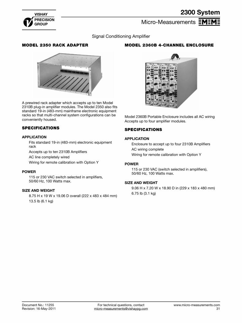
For technical questions, [email protected]
Micro-Measurements
Document No.: 11255Revision: 16-May-2011
www.micro-measurements.com31
2300 System
Signal Conditioning Amplifier
MODEL 2350 RACK ADAPTER
A prewired rack adapter which accepts up to ten Model 2310B plug-in amplifier modules. The Model 2350 also fits standard 19-in (483-mm) mainframe electronic equipment racks so that multi-channel system configurations can be conveniently housed.
SPECIFICATIONS
APPLICATIONFits standard 19-in (483-mm) electronic equipment rackAccepts up to ten 2310B AmplifiersAC line completely wiredWiring for remote calibration with Option Y
POWER115 or 230 VAC switch selected in amplifiers, 50/60 Hz, 100 Watts max.
SIZE AND WEIGHT8.75 H x 19 W x 19.06 D overall (222 x 483 x 484 mm)13.5 lb (6.1 kg)
MODEL 2360B 4-CHANNEL ENCLOSURE
Model 2360B Portable Enclosure includes all AC wiringAccepts up to four amplifier modules.
SPECIFICATIONS
APPLICATIONEnclosure to accept up to four 2310B AmplifiersAC wiring completeWiring for remote calibration with Option Y
POWER115 or 230 VAC (switch selected in amplifiers), 50/60 Hz, 100 Watts max.
SIZE AND WEIGHT9.06 H x 7.20 W x 18.90 D in (229 x 183 x 480 mm)6.75 lb (3.1 kg)
For technical questions, [email protected]
www.micro-measurements.com33
Digital Data Systems
Software for Stress Analysis Testing ..... 34
System 5000 ......................................... 37
System 6000 ......................................... 41
System 7000 ......................................... 50

For technical questions, contact [email protected]
Micro-Measurements
www.micro-measurements.com34
StrainSmart is a ready-to-use, Windows®-based software system for acquiring, reducing, presenting, and storing measurement data from strain gages, strain-gage-based transducers, thermocouples, temperature sensors, LVDTs, potentiometers, piezoelectric sensors, and other commonly used transducers.
And, it is designed to function seamlessly with a variety of Micro-Measurements instrumentation hardware, including System 5000, System 6000, and System 7000 StrainSmart Data Systems.
DESCRIPTION
Ready-to-use StrainSmart software makes test setup fast and easy for strain gages, strain-gage-based transducers, thermocouples, temperature sensors, LVDTs, potentiometers, piezoelectric sensors, and other commonly used transducers. Using the parameters input for sensors, materials, and instrumentation hardware, StrainSmart automatically outputs the results of the test data in engineering units. Test setups and measurement data can also be permanently stored for offline display or for use in databases, word processors, and spreadsheets.StrainSmart has the capability to reduce data in both the time and frequency domains. FFT analysis may be elected for data acquired at scanning rates greater than 100 samples per second.Accurate strain measurements require attention to the unique characteristics of the strain gage and measurement system—thermal output, temperature coefficient of gage factor, and transverse sensitivity of strain gages, as well as nonlinearity errors inherent in the Wheatstone bridge. StrainSmart software takes these into account automatically.All strain-gage bridges are scaled for the number of active bridge arms. Data from measurements with delta, rectangular, and tee rosettes can be reduced to principal strains and stresses, as well as the equivalent stresses for common failure mode criteria.Fully reduced and corrected measurement data can be monitored online, and recorded at predetermined limits or at user-defined intervals.
THE STRAINSMART ADVANTAGE
Strain gage technology is the stress/strain measurement technique most widely used around the world. Over the years, we have developed the tools necessary for accurate acquisition and understanding of strain gage measurements. The primary factors affecting strain gage and instrument performance are incorporated into our extensive selection of Tech Notes, Application Notes, Instruction Bulletins, and other technical publications that are recognized and used as the authoritative references for strain gage measurement by practitioners throughout the world. StrainSmart software automatically applies the
techniques and corrections covered by these publications to your test measurements.
STRAINSMART SOFTWARE FEATURES
• Complete Windows-based software designed for the experimental stress analyst
• Easy-to-use StrainSmart Wizards for fast test setup and for data acquisition, reduction, and presentation
• Sensor-specific assignment of inputs (strain gages, thermocouples, etc.), as well as user-defined assignments for mathematical manipulation of measurement data
• One-touch autobalance• Shunt calibration of strain-gage inputs• Reduced data available offline as Paradox data tables,
ASCII text, HTML or Microsoft Office (Word, Excel, Access) document, or online by OLE Automation connection to spreadsheets, word processors, LabView, and other third-party applications
• Online interactive Help system• Test setup and commonly used parameters available for
saving and reuse for subsequent testing
Software for Stress Analysis Testing
StrainSmart® Data Acquisition System
Document No.: 11268Revision: 04-May-2011

For technical questions, [email protected]
Micro-Measurements
Document No.: 11268Revision: 04-May-2011
www.micro-measurements.com35
Software for Stress Analysis Testing
StrainSmart® Data Acquisition System
ACQUISITION/REDUCTION/PRESENTATION
• Data reduction for delta, rectangular, and tee rosettes, including the conversion of principal strains to stresses
• Calculation of equivalent stresses for common failure mode criteria
• Online monitoring of key channels and/or rosettes in fully reduced and corrected numeric and graphic formats
• Offline presentation of all reduced data in numeric and graphical formats
• FFT analysis (System 6000 and System 7000)• Thermal output compensation• Correction for temperature coefficient of gage factor• Wheatstone bridge nonlinearity correction• Transverse sensitivity correction• Thermocouple linearization
• Scaling for number of active bridge arms• Data storage for later analysis and processing• Record on limits or user-defined time intervals• Automatic audit trail• Self calibration (System 7000)• Barcode input of strain gage datasheet information
MULTI-CHANNEL MEASUREMENTS
Through StrainSmart software, the appropriate setup information is entered—gage factor, materials properties, transducer sensitivities, etc. Using these parameters, StrainSmart automatically outputs the results of test data in engineering units. Setup information and measurement data can also be permanently retained for offline display or for export to databases, word processors, and spreadsheets.
CreateProject
Enter SensorInformation
Enter Materials Properties
Select Hardwareand Enter Settings
Create Assignments of Sensors, Materials and Channels
Scan and Display Fully Corrected Test Data
Software for Stress Analysis Testing
Document No.: 11268Revision: 04-May-2011

For technical questions, contact [email protected]
Micro-Measurements
www.micro-measurements.com42
System 6000
Document No.: 11270Revision: 23-May-2011
StrainSmart® Data Acquisition System
SIZE3.5 H x 19 W x 16 D in (89 x 483 x 381 mm)
WEIGHT17 lb (7.7 kg ) empty19.5 lb (8.8 kg ) loaded with 20 plug-in cards
POWER115 or 230 VAC user-selectable; ±10% of setting; 50/60 Hz; 200W max.
MODEL 6200A SCANNER SPECIFICATIONS
• DC powered (AC optional)• Compact package• Accepts up to 16 plug-in input cards• Supports network communication via a 100BASE-T
Ethernet connection• Multiple units can be linked together to provide
common control and synchronous sampling• Offers user-selectable decimal-based (radix 10) and
binary-based (radix 2) scanning rates• On-board program and data storage• Supports local diagnostics• Supports software identification and setup of each type
of plug-in card
OPERATIONStand-alone or direct software control
INPUTSAccepts up to 16 cards (one channel per card and up to 16 channels per unit)
SYNCMultiple scanners synchronized with synchronization cable links
DATA STORAGECan be configured:Internal: 1 GB solid stateRemovable: ATA form factor removable storage devices, solid state
INTERFACEType: EthernetTopology: 100Base-TProtocol: TCP/IP (HTTP)
OPERATING VIBRATION6G peak in all three axes, sweep to 10 Hz (solid state media)
OPERATING SHOCK20G peak in all three axes, 5 shocks in each axis (solid state media)
SIZE4 H x 10 W x 12.3 D in (102 x 254 x 312 mm)
WEIGHT9.1 lb (4.1 kg) empty, 11.1 lb (5.0 kg) loaded with 16 plug-in cards
POWERDesigned for use with DC power; 9–32 VDC, 100W maxOptional power adapter (Model 6207); 120/240 VAC
SENSOR CARD SPECIFICATIONS
MODEL 6010A STRAIN GAGE CARD

For technical questions, [email protected]
Micro-Measurements
Document No.: 11270Revision: 23-May-2011
www.micro-measurements.com43
System 6000
StrainSmart® Data Acquisition System
• Supports software identification and setup of each type of plug-in card
• Complete strain gage signal conditioner with 16-bit analog-to-digital converter
• Programmable digital filter• Programmable excitation supply per channel. The
supply is settable to 0, 0.5, 1, 2, 5, and 10V. Up to 50 mA of excitation current is available on each channel. Remote sense is provided for full-bridge transducers.
• Programmable gain to complement the excitation steps of 1, 2, 5, and 10V. Full-scale input range will be ±16,383 µε. An excitation setting of 0.5V will use the 1V gain range, but with one-half the resolution. Gain settings are independent per channel.
• Internal bridge completion resistors: 120Ω, 350Ω, and 1000Ω dummy resistors (jumper selectable); 1000 internal half bridge
• Programmable coarse balance range of ±16,300 με (4096 µε steps)
• Fixed low-pass anti-aliasing filter (six-pole)• Two programmable shunt calibration circuits• Input connections to user’s strain gage via nine-pin
D-sub connector
CHANNELS One per card
INPUTS Strain Gages 120Ω, 350Ω,1000Ω quarter bridges; 60Ω to 5000Ω half and full bridgesJumper-selectable completion resistors (0.01% ±2.5 ppm/°C typical)
Measurement RangeNormal range mode: ±16,380 μεHigh range mode: ±163,800 μεLow range mode: ±1638 με
ResolutionNormal range mode: 0.5 μεHigh range mode: 5 μεLow range mode: 0.05 με
Strain Gage Based Transducers60Ω to 5000Ω impedance
Measurement RangeNormal range mode: ±8 mV/V High range mode: ±80 mV/V Low range mode: ±0.8 mV/V
ResolutionNormal range mode: 0.25 µV/V High range mode: 2.5 µV/V Low range mode: 0.025 µV/V
Input Impedance220 MΩ each input
Source Current±25 nA max.
Input ConnectorNine-pin D-sub style
AMPLIFIERZero Temperature Stability±1.5 µV/°C RTI, ±100 µV/°C RTO, after 30-minute warm-up
DC Gain Accuracy and Stability(±0.1% at 23°C) ±50 ppm/°C
Common-Mode Rejection (DC to 60 Hz)100 dB typical
Common-Mode Voltage±6V typical
AC Accuracy (Typical)Input Frequency/Bandwidth 500/3000 50/200 Spurious Free Dynamic Range 100 dB 110 dB Signal to Noise 90 dB 95 dB Signal to Distortion 100 dB 110 dB
Coarse Balance Range±99% of measurement range (typically ±16 300 με)
CALIBRATIONTwo shunt calibration points are available on each channelSwitch-selectableCalibration switches, A and B, are software selectable
EXCITATION0.0, 0.5, 1.0, 2.0, 5.0, and 10.0 VDC. Software programmable.
Accuracy±3 mV typical
Current50 mA max; over-current protected
Load Regulation<0.05% of full scale for a load variation of 10% to 100% of full load
Temperature StabilityBetter than ±0.005%/°C
Remote Sense15Ω maximum lead resistance

For technical questions, contact [email protected]
Micro-Measurements
www.micro-measurements.com44
System 6000
Document No.: 11270Revision: 23-May-2011
StrainSmart® Data Acquisition System
A/D CONVERTERType16-bit successive approximation with integrated sample and hold
Integral Linearity Error±2 LSB
FILTERSLinear phase, analog, 6-pole anti-aliasing filter, and 256-tap, programmable, FIR digital filter (lowpass)
Passband FrequencyUser-selectable 1 Hz to 4 kHz
ANALOG OUTPUT (6010A Version Only)Type±5.00V max for typical full-scale input of ±16,380 με
Output Load2000Ω min
BandwidthDC to 15 kHz (–0.5 dB typical)
MODEL 6020A THERMOCOUPLE CARD
• Complete thermocouple signal conditioner with 16-bit analog-to-digital converter
• Programmable digital filter• Programmable common cold-junction reference• Compensation is provided for J, K, T, N, E, R, S, and B
thermocouple types• Fixed low-pass anti-aliasing filter (six-pole)• Connections to user’s thermocouple circuit via a
removable three-terminal screw connector
CHANNELSOne per card
INPUTSThermocouple types J, K, T, E, N, R, S, B. Built-in electronic cold-junction compensation. Software-selectable.Open sensor detection
Input Impedance10 MΩ differential, 100 KΩ common mode
Source Current±0.5 nA typical; ±5 nA max.
Input ConnectorThree-position screw terminal
AMPLIFIERZero Temperature Stability±1.5 µV/°C RTI, ±100 µV/°C RTO, after 30-minute warm-up
DC Gain Accuracy and Stability0.05% at 23°C ± 50 ppm/°C
Common-Mode Rejection (DC to 60 Hz)100 dB typical
Common-Mode Voltage±6V typical
AC Accuracy (Typical)Input Frequency/Bandwidth 500/3000 50/200 Spurious Free Dynamic Range 100 dB 110 dB Signal to Noise 90 dB 95 dB Signal to Distortion 100 dB 110 dB
MEASUREMENT RANGE±81.9 mV
RESOLUTION2.5 µV
A/D CONVERTER Type16-bit successive approximation with integrated sample and hold
Integral Linearity Error±2 LSB
FILTERSLinear phase, analog, 6-pole anti-aliasing filter, and 256-tap, programmable, FIR digital filter (lowpass)
Passband FrequencyUser-selectable 1 Hz to 4 kHz

For technical questions, [email protected]
Micro-Measurements
Document No.: 11270Revision: 23-May-2011
www.micro-measurements.com45
System 6000
StrainSmart® Data Acquisition System
MODEL 6030A HIGH-LEVEL INPUT CARD
• Complete high-level signal conditioner with 16-bit analog-to-digital converter
• Programmable gain• Programmable digital filter• Programmable excitation supply. The supply is settable
to 0, 0.5, 1, 2, 5, 10, 15, 20, 24, and 30V. Up to 50 mA of current is available on each channel
• Fixed low-pass anti-aliasing filter (six-pole)• Input connections to user’s voltage source via nine-pin
D-sub connector• Analog output
CHANNELSOne per card
INPUTS DC volts (differential)
Input Impedance22 MΩ each input
Source Current±2 nA typical±100 nA max
Input ConnectorNine-pin D-sub style
AMPLIFIERZero Temperature Stability±2 µV/°C RTI, typical. ±100 µV/°C RTO, after 30-minute warm-up
DC Gain Accuracy and Stability±0.05% at 23°C ± 20 ppm/°C
Common-Mode Rejection (DC to 60 Hz)86 dB typical at X1 gain94 dB typical at X10 gain
Common-Mode Voltage±12V typical
AC Accuracy (Typical) Input Frequency/Bandwidth 500/3000 50/200 Spurious Free Dynamic Range 100 dB 110 dB Signal to Noise 90 dB 95 dB Signal to Distortion 100 dB 110 dB
MEASUREMENT RANGES±1, ±2, ±5, ±10 VDC
RESOLUTION30.5, 61, 152.5, 305 µV
EXCITATION0, 0.5, 1.0, 2.0, 5.0, 10.0, 15.0, 20.0, 24.0, 30.0 VDC
Accuracy±10 mV typical at 0 to 24 VDC; ±5% at 30 VDC
Current50 mA max. Over-current protected
Load Regulation<±0.05% of full scale for a load variation of 10% to 100% of full load
Temperature StabilityBetter than ±0.005%/°C
A/D CONVERTERType16-bit successive approximation with integrated sample and hold
Integral Linearity Error±2 LSB
FILTERSLinear phase, analog, 6-pole anti-aliasing filter, and 256-tap, programmable, FIR digital filter (lowpass)
Passband FrequencyUser-selectable 1 Hz to 4 kHz
ANALOG OUTPUT (6030A Version Only)Type±5.00V max for typical full-scale input of ±32,767 με
Output Load2000Ω min
BandwidthDC to 15 kHz (–0.5 dB typical)

For technical questions, contact [email protected]
Micro-Measurements
www.micro-measurements.com46
System 6000
Document No.: 11270Revision: 23-May-2011
StrainSmart® Data Acquisition System
MODEL 6040A LVDT CARD
• Complete LVDT signal conditioner with 16-bit analog-to-digital converter
• Programmable digital filter• Independent AC excitation supply• Programmable gain steps of 1, 2, 5, and 10• Supports six-, five-, four-, and three-wire transducers• Fixed low-pass anti-aliasing filter (six-pole)• Excitation reference provided for calibration• Input connections to user’s transducer via nine-pin
D-sub connector
CHANNELSOne per card
INPUTS3- to 6-wire transducers
Input Impedance10 MΩ each input
Source Current±2 nA typical; ±100 nA max
Input ConnectorNine-pin D-sub style
AMPLIFIERZero Temperature Stability±2 µV/°C RTI, typical. ±100 µV/°C RTO, after 30-minute warm-up
Gain Accuracy and Stability±0.25% typical
Common-Mode Rejection (DC to 60 Hz)86 dB typical at X1 gain94 dB typical at X10 gain
Common-Mode Voltage±12V typical
MEASUREMENT RANGES±0.5, ±1, ±2.5, ±5 VRMS
RESOLUTION15.25, 30.5, 76.2, 152.5 µVRMS
CALIBRATIONExcitation sample
EXCITATION3.0 VRMS at 2500, 5000, or 10000 Hz sine waveSoftware-selectable
Accuracy±5 mVRMS typical
Current±50 mA max. Over-current protected
Load Regulation<±0.1% of full scale for a load variation of 10% to 100% of full load
Temperature StabilityBetter than ±0.05%/°C
A/D COVERTERType16-bit successive approximation with integrated sample and hold
Integral Linearity Error±2 LSB
FILTERSButterworth, six-pole anti-aliasing analog filter, and 256-tap, programmable, FIR digital filter (lowpass)
Passband FrequencyUser-selectable 1 Hz to 4 kHz
ANALOG OUTPUT (6040A Version Only)Linear Output: ± 5.00V for typical full-scale inputOutput Load: 2000Ω minBandwidth: DC to 1 kHz (–3 dB typical)

For technical questions, [email protected]
Micro-Measurements
Document No.: 11270Revision: 23-May-2011
www.micro-measurements.com47
System 6000
StrainSmart® Data Acquisition System
MODEL 6050 PIEZOELECTRIC CARD
• Complete piezoelectric signal conditioner with 16-bit analog-to-digital converter
• Supports both VM (voltage mode, low impedance) and CM (charge mode, high impedance) type piezoelectric transducers
• Programmable constant current excitation supply for VM transducers is software settable to 1, 2, 4, 5, 10 and 20 mA
• Programmable gain steps of 1, 2, 5, and 10 for VM transducers and steps of 1, 2, 5, 10, 20, 50 and 100 for CM transducers
• Programmable digital filter• Fixed low-pass anti-aliasing filter (six-pole)• Input connections to user’s transducer via BNC
connector
CHANNELSOne per card
INPUTSVoltage mode (VM) or charge mode (CM) piezoelectric type transducers (type is switch-selectable)
CouplingCM Type: Charge amplifier with software-selectable time constants of 0.5 and 5 secondsVM Type: AC coupling to remove DC bias voltage with high pass response of 0.1 Hz (-3 dB)
Input ConnectorFemale BNC
AMPLIFIERZero Temperature Stability±10 µV/°C RTI, typical, after 30-minute warm-up
Charge Amplifier Zero Stability±1.2 pC/°C RTI typical at 0.5 second time constant
DC Gain Accuracy and Stability±0.1% at +23°C; ±25 ppm/°C
AC Accuracy (Typical at X2 Gain Step)Input Frequency/Bandwidth 500/3000 50/200 Spurious Free Dynamic Range 100 dB 110 dB Signal to Noise 90 dB 95 dB Signal to Distortion 100 dB 110 dB
MEASUREMENT RANGESVM Type Transducers±10.5V, ±5.25V, ±2.1V, and ±1.05V
CM Type Transducers±200 000 pC, ±100 000 pC, ±40 000 pC, ±20 000 pC, ±10 000 pC, ±4000 pC, and ±2000 pC
RESOLUTION0.0015% of range
CALIBRATIONExcitation sample
EXCITATION0, 1, 2, 4, 5, 10 and 20 mA selections for VM type transducers
Accuracy±1% + (±30 µA) typical at 1 to 20 mA
Voltage Compliance0 to 28V
Temperature Stability±50 ppm/°C
A/D CONVERTERType16-bit successive approximation with integrated sample and hold
Integral Linearity Error ±2 LSB
FILTERSLinear phase, analog, 6-pole anti-aliasing filter, and 256-tap, programmable, FIR digital filter (lowpass)
Passband FrequencyUser-selectable 1 Hz to 4 kHz

For technical questions, contact [email protected]
Micro-Measurements
www.micro-measurements.com48
System 6000
Document No.: 11270Revision: 23-May-2011
StrainSmart® Data Acquisition System
MODEL 6095 DIGITAL/TACHOMETER CARD
• Multi-function digital input card• Relay output for control functions• Compatible with all System 6000 hardware• Supported by StrainSmart software
When used in conjunction with Micro-Measurements StrainSmart® Software, the Model 6095 Digital/Tachometer Card enables the user to capture and reduce data in any one of five operating modes:
• Tachometer Mode• Interval Mode• Quadrature Mode• Counter Mode• Digital Input Mode
Depending upon the mode selected, data can be reduced as a digital input; counts; interval counts; pulses; rate; shaft angle; RPM; radians or degrees per second; elapsed time (milliseconds, seconds or minutes); or calculated values.
Multiple Model 6095 Cards can be used in each system, and each card in a system can be configured individually to any operating mode. However, the relay provides one distinct control function (on/off control for testing machines, etc.) per system when using a Model 6100 Scanner, or one per scanner when using multiple Model 6200 Scanners.
The Model 6095 is compatible with all Model 6100 and 6200 Scanners. It is supported by Version 3.0, and later, StrainSmart Software; no-charge upgrades are available upon request.
INPUT CONNECTORNine-pin, D-sub style
RELAY OUTPUTSQuantityOne
ConfigurationNO and NC, 500 mA contact at 30 VAC or 30 VDC into resistive load
DIGITAL INPUTSQuantityFour
ConfigurationOptically isolated. TTL Schmitt-trigger input thresholds accept up to 28 VDC without damage. 2.23Ω pull-up resistors can be selected for each input.
Impedance50 kΩ
Data RateDC to 200 kHz
Accessory Supply5 Volt ± 5%, 75 mA
CONFIGURATIONS
StrainSmart Data Systems can be configured in a variety of ways to meet the specific requirements of each user. Each system consists of (1) software, (2) instrumentation hardware, and (3) personal computer.
SOFTWARE
It is strongly recommended that StrainSmart Software be installed on a Windows-based personal computer for data acquisition, reduction, display, and storage.
While the hardware for StrainSmart Data Systems may be used with third-party data acquisition software, total system operation becomes the user’s responsibility when third-party software is used.
INSTRUMENTATION HARDWARE
In addition to a one-time purchase of StrainSmart Software, the initial purchase for each system would normally include one of the following:
• System 6000 with PCI or PCIe Interface—Model 6101PCI or Model 6101PCIe Interface Card, at least one Model 6100 Scanner, and at least one Model 6010, 6020, 6030, 6040, 6050, or 6095 Input Card
• System 6000 with Ethernet Interface—At least one Model 6200 Scanner and at least one Model 6010, 6020, 6030, 6040, 6050, or 6095 Input Card

For technical questions, [email protected]
Micro-Measurements
Document No.: 11270Revision: 23-May-2011
www.micro-measurements.com49
System 6000
StrainSmart® Data Acquisition System
PERSONAL COMPUTER REQUIREMENTS
In addition to StrainSmart® Software and Hardware purchased from Micro-Measurements, the system requires access to a properly configured personal computer. The hardware requirements for StrainSmart are:
• Fast Intel Core-2 Duo or better• 4 GB of memory or better• 20 GB of available free space or better• XGA (1024 x 768) or better
STRAINSMART SOFTWARE
StrainSmart Software is designed to function with all System 5000, 6000, and 7000 hardware. It contains everything needed to acquire, reduce, display, and store measurement data, including:
• StrainSmart Main Operating Program• Offline Data Presentation Program• Interactive Help System
All components are supplied on CD-ROM along with a utility for installing them.
An unlimited number of installations can be made within your facility with the one-time purchase of a single copy of StrainSmart.

For technical questions, contact [email protected]
Micro-Measurements
www.micro-measurements.com50
FEATURES
• Stable, accurate, low-noise signal conditioning• Measurement accuracy ±0.05%• Measurement resolution 0.5 microstrain• Individual input cards for strain gage and strain-gage
based transducers, thermocouples, sensors with high-level voltage outputs, and LVDTs
• Electronically selectable, built-in bridge completion for 120-, 350-, and 1000-ohm strain gages
• Virtually unlimited number of channels in increments of 8 channels
• Maximum scan rate of 2048 samples per second• Self calibration traceable to NIST standard• Simultaneous sampling with anti-aliasing filter and
analog-to-digital conversion for each channel• Selectable digital filtering of measurement signals• High-speed Ethernet network interface• Remote Utility includes capability for acquiring data
without connection to a computer (field upgradeable)
DESCRIPTION
Micro-Measurements System 7000 builds upon the years of experience gained since the introduction of Systems 4000, 5000, and 6000 by continuing to provide a complete hardware/software approach to data acquisition, reduction, and presentation for strain gages and related sensors for stress analysis testing.
System 7000 hardware is designed to incorporate all the features required for precision strain measurement in a high channel density enclosure. Strain gages, strain-gage-based transducers, thermocouples, LVDTs, and other sensors with high level voltage outputs can be intermixed in groups of eight (8) by choosing the appropriate sensor card for up to 128 channels in a 4U height, 19-inch rack-mountable scanner (7000-128-SM). A 32-channel scanner is also available (7000-32-SM). The Ethernet interface allows flexible positioning of scanners, and multiple scanners can easily be synchronized using a single sync cable (maximum length 100 meters). A system can be configured with virtually an unlimited number of sensors.
System 7000 is a high performance data acquisition instrument with measurement accuracy of ±0.05% of full scale. Each sensor card employs a 24-bit analog-to-digital converter enabling 0.5 microstrain resolution. Scan rates up to 2048 samples per second are available for
System 7000
StrainSmart® Data Acquisition System
Document No.: 11271Revision: 17-May-2011
simultaneous reading of all sensor inputs. A combination of analog and flexible Finite Impulse Response (FIR) filters are available to provide adequate anti-alias filtering at all scanning rates. Each sensor card has high-capacity nonvolatile data storage capability. Electronically selectable bridge completion resistors allow the user to choose between 120-, 350-, and 1000-ohm strain gages through software selection.
Several design features are provided to reduce total cost of ownership. System 7000 is capable of self-calibration with a removable calibration reference (7000-SM-VC). Calibration can be performed anywhere and there is no need to return the entire system to the factory for calibration. Down-time while waiting for calibration is essentially eliminated. Input connectors are RJ-45 type and assembly time is fast using simple cable crimping tools. Sensor input cards all use common Analog Input Cards (Model 7003-8-A-I), which thereby allow users to interchange sensor input cards with analog input cards. Individual scanners can be separated and located near sensors to reduce sensor cabling costs.
A feature for acquiring data without a connection to a computer has been added. This Remote Utility Feature is field upgradeable on units purchased prior to the introduction of this feature. With this feature, data can be collected then exported to other applications for analysis.

For technical questions, [email protected]
Micro-Measurements
Document No.: 11271Revision: 17-May-2011
www.micro-measurements.com51
System 7000
StrainSmart® Data Acquisition System
SCANNER SPECIFICATIONS (128 CHANNEL VERSION)
The purpose of the Model 7000-128-SM Scanner is to house and retain the acquisition cards, regulate power to the cards, establish and maintain communication between the Ethernet interface and the input cards, synchronize the analog-to-digital converters in the system, and provide visual status information to the operator.
CAPACITYUp to 16 Input Cards. 128 channels maximum
CONFIGURATIONSRack-mount (19-inch) or bench-top
LCD DISPLAY64 x 128 white LED-backlit display
LED PANEL128 individual red/green LEDs; one per channel
KEYPADMembrane. 20-key; 12-key numeric keypad, 5 key navigation keypad, and 3 soft-keys
INPUT POWER11–32 VDC, 30A max
POWER INDICATIONGreen LED (illuminated when power is on)
ETHERNET INTERFACEIEEE 802.3, 802.3u 10Base-T, 100Base-TX, half- and full-duplex, auto-detect
COMPACT FLASH® CAPACITY1 GB supplied (removable)
PROCESSOR250 MHz floating point digital signal processor
MEMORY64 MB SDRAM
INTERNAL COMMUNICATIONAsynchronous command bus, synchronous data bus
SYSTEM SYNCHRONIZATIONConnections: Sync In, Sync OutTopology: Daisy-chain Cable Connection: TIA/EIA RJ-45, Category 5Max. Distance: 100m
SYSTEM CALIBRATION REFERENCEFirmware-controlledDrift: 1.9 ppm/°C ±0.6 μV/°C typical, 9.4 ppm/°C ±2.1 μV/°C maximumResolution: 150 μV nominalVoltage Range: ±5V
DIMENSIONS7.5 H x 17.5 W x 13.5 D in (190 x 445 x 343 mm)
WEIGHT20 lb (9.1 kg)
SCANNER SPECIFICATIONS (32-CHANNEL VERSION)
The purpose of the Model 7000-32-SM Scanner is to house and retain the acquisition cards, regulate power to the cards, establish and maintain communication between the Ethernet interface and the input cards, synchronize the analog-to-digital converters in the system, and provide visual status information to the operator.
CAPACITYUp to 4 Input Cards. 32 channels maximum
CONFIGURATIONSBench-top
System 7000
Document No.: 11271Revision: 17-May-2011

For technical questions, contact [email protected]
Micro-Measurements
www.micro-measurements.com52
System 7000
Document No.: 11271Revision: 17-May-2011
StrainSmart® Data Acquisition System
LCD DISPLAY64 x 128 white LED-backlit display
LED PANEL32 individual red/green LEDs; one per channel
KEYPADMembrane. 20-key; 12-key numeric keypad, 5 key navigation keypad, and three soft-keys
INPUT POWER11–32 VDC, 30A max
POWER INDICATIONGreen LED (illuminated when power is on)
ETHERNET INTERFACEIEEE 802.3, 802.3u 10Base-T, 100Base-TX, half- and full-duplex, auto-detect
COMPACT FLASH® CAPACITY1 GB supplied (removable)
PROCESSOR250 MHz floating point digital signal processor
MEMORY64 MB SDRAM
INTERNAL COMMUNICATIONAsynchronous command bus, synchronous data bus
SYSTEM SYNCHRONIZATIONConnections: Sync In, Sync OutTopology: Daisy-chain Cable Connection: TIA/EIA RJ-45, Category 5Max. Distance: 100m
SYSTEM CALIBRATION REFERENCEFirmware-controlledDrift: 1.9 ppm/°C ± 0.6 μV/°C typical, 9.4 ppm/°C ± 2.1 μV/°C maximumResolution: 150 μV nominalVoltage Range: ±5V
DIMENSIONS7.5 H x 7.1 W x 13.5 D in (190 x 180 x 343 mm)
WEIGHT10.1 lb (4.6 kg)
STRAIN GAGE INPUT CARDS
A choice of two Strain Gage Input Cards (7003-8-SG or 7003-8-SG-A) are used in conjunction with the Model 7003-8-A-I Analog Input Card to perform bridge excitation, bridge completion, shunt calibration, and signal conditioning for eight quarter, half, and full bridges. Note that the 7003-8-SG-A Strain Gage Input Card with Analog Output has an analog output which provides an amplified representation of the input source.
CHANNELSEight per card
INPUTSSoftware selectable for S+/S-, VCAL+/VCAL-, or excitation Strain Gage: 120Ω, 350Ω, 1000Ω quarter-bridges; 60Ω to 5000Ω half- and full-bridges Input Impedance: 220 MΩ nominal each input Source Current: ±5 nA per volt excitation
ANALOG OUTPUT (MODEL 7003-8-SG-A ONLY)Fixed Gain: 50.3 V/V ±1%Output Range: ±10V minOutput Load: 2000Ω minBandwidth: DC to 4.2 kHz (–3 dB ±0.25 dB)
MEASUREMENT RANGE AND RESOLUTIONTotal range depends upon excitation setting (see table).Resolution: 0.5 με (GF=2)
EXCITATION VOLTS
MEASURING RANGEIncludes Full Scale Imbalance
µε @ GF=2 mV/V0 48,000 24*
0.25 100,000 500.5 96,000 480.75 70,000 35
1 48,000 242 24,000 123 16,000 84 50,000 255 40,000 206 35,000 17.57 30,000 158 25,000 12.59 20,000 1010 20,000 10
*Based on 1 volt excitation

For technical questions, [email protected]
Micro-Measurements
Document No.: 11271Revision: 17-May-2011
www.micro-measurements.com53
System 7000
StrainSmart® Data Acquisition System
INPUT CONNECTOREight-pin TIA/EIA RJ-45 (Amp type 554739 or equivalent)
AMPLIFIERZero Temperature Stability: ±1 μV/°C RTI, after 60-minute warm-upDC Gain Accuracy and Stability: ±0.05%; ±50 ppm/°C (1 year without periodic VCAL) Analog Input (Including Full-Scale Balance):
Low Range: ±50 mVHigh Range: ±220 mVLinearity: ±0.02% of Full ScaleCommon-Mode Rejection: >90 dB (DC to 60 Hz)Common-Mode Voltage Range: ±12V typical
BALANCEType: Software (mathematical)Range: Full ADC range
EXCITATIONSelection: Software controlled Resolution: 1 mV Accuracy: ±4 mV typical (Firmware measures excitation variations during arming process) Current: 50 mA max. per channel Over-current limited Over-current indication Load Regulation: <0.05% of full scale for 10% to 100% of full scale load with remote senseTemperature Stability: ±10 ppm/°C
QUARTER-BRIDGE COMPLETIONSelection: Firmware controlledAccuracy and Drift:
120Ω and 350Ω: ±0.01%, 2.8 ppm/°C max.1 kΩ: ±0.01%, 1.6 ppm/°C max. (socketed)
SHUNT CALIBRATIONSelection: Firmware controlled Configuration:
Internal: P– to D120, P– to D350, P– to D1000Remote: RcalA to RcalB
Sockets: Tin-platedLevels: Simulates 10,000 με @ GF = 2.0Values:
P- to D120: 5940Ω ±0.1%P- to D350: 17,325Ω ±0.1%P- to D1000: 49,500Ω ±0.1%
SYSTEM CALIBRATIONFirmware controlled Calibration voltage: Supplied by Model 7000-SM-VC voltage calibration cardType: Ten point calibration
SIZE6.5 L x 6.5 W x 0.9 H in (165 x 165 x 23 mm)
WEIGHT0.45 lb (0.2 kg)
THERMOCOUPLE INPUT CARD
The Model 7003-8-TC Thermocouple Input Card is used in conjunction with the Model 7003-8-A-I Analog Input Card to perform signal conditioning and cold-junction compensation for thermocouple types J, K, T, E, N, R, S, and B.
CHANNELSEight per card
INPUTSSupported Thermocouple Types: J, K, T, E, N, R, S, B Cold-junction compensation, software-selectableOpen-sensor detectionInput Impedance: 220 MΩ nominal each input
INPUT CONNECTORSFive-position connector with screw terminals
AMPLIFIERZero Temperature Stability: ±2 μV/°C RTI, ±10 μV/°C RTO, after 60-minute warm-up DC Gain Accuracy and Stability: ±0.1%; ±30 ppm /°CLinearity: ±0.02% of Full ScaleCommon Mode Rejection (DC to 60 Hz): >90 dBCommon Mode Voltage Range: ±12V typical
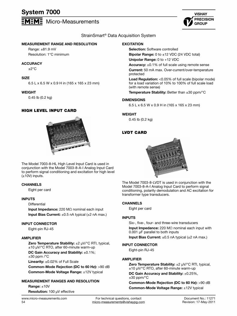
For technical questions, contact [email protected]
Micro-Measurements
www.micro-measurements.com54
System 7000
Document No.: 11271Revision: 17-May-2011
StrainSmart® Data Acquisition System
MEASUREMENT RANGE AND RESOLUTIONRange: ±81.9 mVResolution: 1°C minimum
ACCURACY±2°C
SIZE6.5 L x 6.5 W x 0.9 H in (165 x 165 x 23 mm)
WEIGHT0.45 lb (0.2 kg)
HIGH LEVEL INPUT CARD
The Model 7003-8-HL High Level Input Card is used in conjunction with the Model 7003-8-A-I Analog Input Card to perform signal conditioning and excitation for high level (±10V) inputs.
CHANNELSEight per card
INPUTSDifferentialInput Impedance: 220 MΩ nominal each inputInput Bias Current: ±0.5 nA typical (±2 nA max.)
INPUT CONNECTOREight-pin RJ-45
AMPLIFIERZero Temperature Stability: ±2 μV/°C RTI, typical, ±10 μV/°C RTO, after 60-minute warm-upDC Gain Accuracy and Stability: ±0.1%; ±30 ppm /°CLinearity: ±0.02% of Full ScaleCommon-Mode Rejection (DC to 60 Hz): >90 dBCommon-Mode Voltage Range: ±12V typical
MEASUREMENT RANGES AND RESOLUTIONRange: ±10VResolution: 100 μV effective
EXCITATIONSelection: Software controlledBipolar Range: 0 to ±12 VDC (24 VDC total) Unipolar Range: 0 to +12 VDCAccuracy: ±0.1% of full scale using remote senseCurrent: 50 mA max. Over-current/over-temperature protectedLoad Regulation: <0.05% of full scale (bipolar mode) for a load variation of 10% to 100% of full scale load (with remote sense) Temperature Stability: Better than ±30 ppm/°C
DIMENSIONS6.5 L x 6.5 W x 0.9 H in (165 x 165 x 23 mm)
WEIGHT0.45 lb (0.2 kg)
LVDT CARD
The Model 7003-8-LVDT is used in conjunction with the Model 7003-8-A-I Analog Input Card to perform signal conditioning, polarity demodulation and AC excitation for transformer type transducers.
CHANNELSEight per card
INPUTSSix-, five-, four- and three-wire transducersInput Impedance: 220 MΩ nominal each input with 0.001 μF parallel to both inputsInput Bias Current: ±0.5 nA typical (±2 nA max.)
INPUT CONNECTOREight-pin RJ-45
AMPLIFIERZero Temperature Stability: ±2 μV/°C RTI, typical, ±10 μV/°C RTO, after 60-minute warm-upDC Gain Accuracy and Stability: ±0.25%, ±30 ppm/°CCommon-Mode Rejection (DC to 60 Hz): >90 dB Common-Mode Voltage Range: ±12V typical

For technical questions, [email protected]
Micro-Measurements
Document No.: 11271Revision: 17-May-2011
www.micro-measurements.com55
System 7000
StrainSmart® Data Acquisition System
POST DEMODULAR FILTERType: Low-Pass Frequency: 1.0 kHz @ –3 dB Number of Poles: Six Topology: Butterworth
MEASUREMENT RANGE AND RESOLUTIONRange: ±5 VRMS Resolution: 50 μVRMS effective
EXCITATIONSelection: Software controlledFrequency: 2500, 5000, or 10000 Hz sine wave Amplitude: 3 VRMS Accuracy: ±0.5% of full scale typical Current: 50 mA max. Over-current/over-temperature protectedLoad Regulation: <0.1% of full scale for a load variation of 10% to 100% of full scale load Temperature Stability: Better than ±0.05%/°C
SIZE6.5 L x 6.5 W x 0.9 H in (165 x 165 x 23 mm)
WEIGHT0.45 lb (0.2 kg)
ANALOG INPUT CARD
The Model 7003-8-A-I Analog Input Card performs the analog anti-alias filtering, analog-to-digital conversion and data storage for the System. The Model 7003-8-A-I is used in conjunction with a Sensor Input Card, which performs the sensor-specific analog conditioning.
The Model 7003-8-A-I consists of eight dedicated 3-pole constant delay analog anti-alias filters, eightfully synchronized, 24 bit analog-to-digital convertersoperating at 40k samples/second/channel, a dedicateddigital signal processor to perform scaling and digitalfiltering, a pretrigger buffer with a capacity of overone-half million samples per channel, and 1 GB ofCompactFlash® memory for data storage.
CHANNELSEight per card
A/D CONVERTERQuantity: Eight (one per channel)Architecture: Sigma-deltaResolution: 24 bitsConversion Rate:
Radix-10: 40k samples/second/channel Radix-2: 40.96k samples/second/channel
DATA RECORDING RATES2048, 1024, 512, 256, 128, or 64 samples/second/ channel (radix-2)2000, 1000, 500, 200, 100, or 10 samples/second/ channel (radix-10)
PRE-TRIGGER BUFFERType: SDRAM, firmware-controlledDepth: 645,276 samples/channel
ANALOG ANTI-ALIAS FILTERType: Low-passFrequency: 3.5 kHz @ –3 dBNumber of Poles: ThreeTopology: GIC, constant delay
PROCESSORType: 32-bit floating point digital signal processor250 MHz operating frequency
RAMType: SDRAM Size: 64 MB
PROGRAM AND CALIBRATION DATA STORAGEType: Flash Memory Size: 1 MB
DATA STORAGEType: Sandisk Ultra-Series II® CompactFlash Quantity: One per cardCapacity: 1 GB supplied. Removable
SIZE6.8 L x 6.5 W x 0.7 H in (173 x 165 x 18 mm)
WEIGHT0.35 lb (0.16 kg)

For technical questions, contact [email protected]
Micro-Measurements
www.micro-measurements.com56
System 7000
Document No.: 11271Revision: 17-May-2011
StrainSmart® Data Acquisition System
CONFIGURATIONS
StrainSmart® Data Systems can be configured in a variety of ways to meet the specific requirements of each user. Each system consists of (1) software, (2) instrumentation hardware, and (3) personal computer.
SOFTWARE
It is strongly recommended that StrainSmart Software be installed on a Windows-based personal computer for data acquisition, reduction, display, and storage.
While the hardware for StrainSmart Data Systems may be used with third-party data acquisition software, total system operation becomes the user’s responsibility when third-party software is used.
INSTRUMENTATION HARDWARE
In addition to a one-time purchase of StrainSmart Software, the initial purchase for each system would normally include one of the following:
System 7000 with Ethernet Interface—At least one Model 7000-128-SM Scanner or Model 7000-32-SM Scanner, and at least one Model 7003-8-SG, 7003-8-SG-A, 7003-8-HL, or 7003-8-TC Input Card, each connected to a Model 7003-8-A-I Analog Input Card
PERSONAL COMPUTER REQUIREMENTS
In addition to StrainSmart Software and Hardware purchased from Micro-Measurements, the system requires access to a properly configured personal computer. The hardware requirements for StrainSmart are:
• Fast Intel Core-2 Duo or better• 4 GB of memory or better• 20 GB of available free space or better• XGA (1024 x 768) or better
STRAINSMART SOFTWARE
StrainSmart Software is designed to function with all System 5000, 6000, and 7000 hardware. It contains everything needed to acquire, reduce, display, and store measurement data, including:
• StrainSmart Main Operating Program• Offline Data Presentation Program• Interactive Help System
All components are supplied on CD-ROM along with a utility for installing them.
An unlimited number of installations can be made within your facility with the one-time purchase of a single copy of StrainSmart.

System 8000
System 8000 StrainSmart® Data Acquisition SystemFEATURES
• Eight software-selectable input channels• Up to 16 scanners can be used concurrently• Supported inputs include:
❍❍ Strain gage (quarter-, half-, and full-bridges)❍❍ Strain-gage-based transducer❍❍ High-level voltage signal❍❍ Thermocouples
• RJ45 input connectors for each input channel• Scanning rates are 1000, 500, 200, 100, and
10 samples/second• Compact size and ruggedized enclosure• Ethernet network architecture• Optional self-calibration functionality available
DESCRIPTION
System 8000 from Micro-Measurements is a versatile, precision data acquisition instrument system intended for static and dynamic test and measurement applications.
The system includes a scanner with 8 channels of data acquisition. A 10’ crossover Ethernet cable is also included. The scanners may be used separately or up to 16 scanners can be used concurrently for a maximum of 128 channels.
Each channel can be configured, via software, to accept signals from strain gages or strain-gage-based transducers, thermocouples, or high level voltage sensors. Strain gage channels accept full-, half-, or quarter-bridge configurations and have the required bridge completion components for 120-, 350-, and 1000-ohm bridges. Each scanner operates independently; multiple scanners are not synchronized.
The data is processed in a modern 24-bit digital signal processor and filtering is performed using Finite Impulse Response (FIR), multi-stage filters. This provides excellent noise rejection and stability and unsurpassed measurement accuracy.
The Model 8000-8-SM Scanner communicates with a host personal computer (PC) via an Ethernet connection. Micro-Measurements StrainSmart® software is optimal for configuring, controlling, and acquiring data from the System 8000. A Programmer’s Reference Kit provides documentation, programming examples, and instrument drivers to assist with custom software development.
SUPPORTED SENSORS
Each channel can be defined, via software, to be one of the following sensor types:
• Strain gage (quarter-, half-, and full-bridges)• Strain-gage-based transducer• High-level voltage signal• Thermocouples
SAMPLING
All channels in each scanner are sampled simultaneously. Each channel’s 24-bit analog-to-digital converter over-samples data at a rate of 128k samples/second, and provides high quality, low noise data (without the need for signal averaging) at rates up to 1000 samples/second/channel.
SCANNING RATES
The system provides numerous scan rates and Finite Impulse Response (FIR) filters are automatically selected to provide suitable filtering at each rate to avoid aliasing. Sampling rates for the Model 8000-8-SM are 1000, 500, 200, 100, and 10 samples/second.
COMPACT, RUGGEDIZED ENCLOSURE
The Model 8000-8-SM has 8 channels in a 1U (1.72 inch) height enclosure. The aluminum-alloy enclosure provides superior strength and durability. A rack mount kit is also available.
RJ45 INPUT CONNECTORS
Each channel input connector is an 8-pin TIA/EIA RJ45.
RELAY OUTPUT
A relay output is provided to control external hardware.
ETHERNET NETWORK ARCHITECTURE
The system communicates over an IEEE-802.3u 100Base-TX or an IEEE-802.3 10Base-T Ethernet Network. The firmware uses separate command and data ports and employs a reliable TCP-based protocol to prevent data loss.
DC OPERATION
Model 8000 operates on 10-32 VDC power. This can be from the included power supply or by using a separate AC-to-DC converter or DC supply such as a battery.
MODEL 8000-8-SM POWER SOURCE
The Model 8000 is a DC-powered instrument. The system accommodates DC input voltages from 10 to 32 volts. The included power supply provides the required AC-to-DC conversion and up to 30 watts of power to the system. An alternate DC power source can be used provided that it supplies enough power to meet the
System 8000 StrainSmart® Data Acquisition System
For technical questions, contact [email protected]
www.micro-measurements.com 57
Document No.: 11271Revision: 17-May-2011
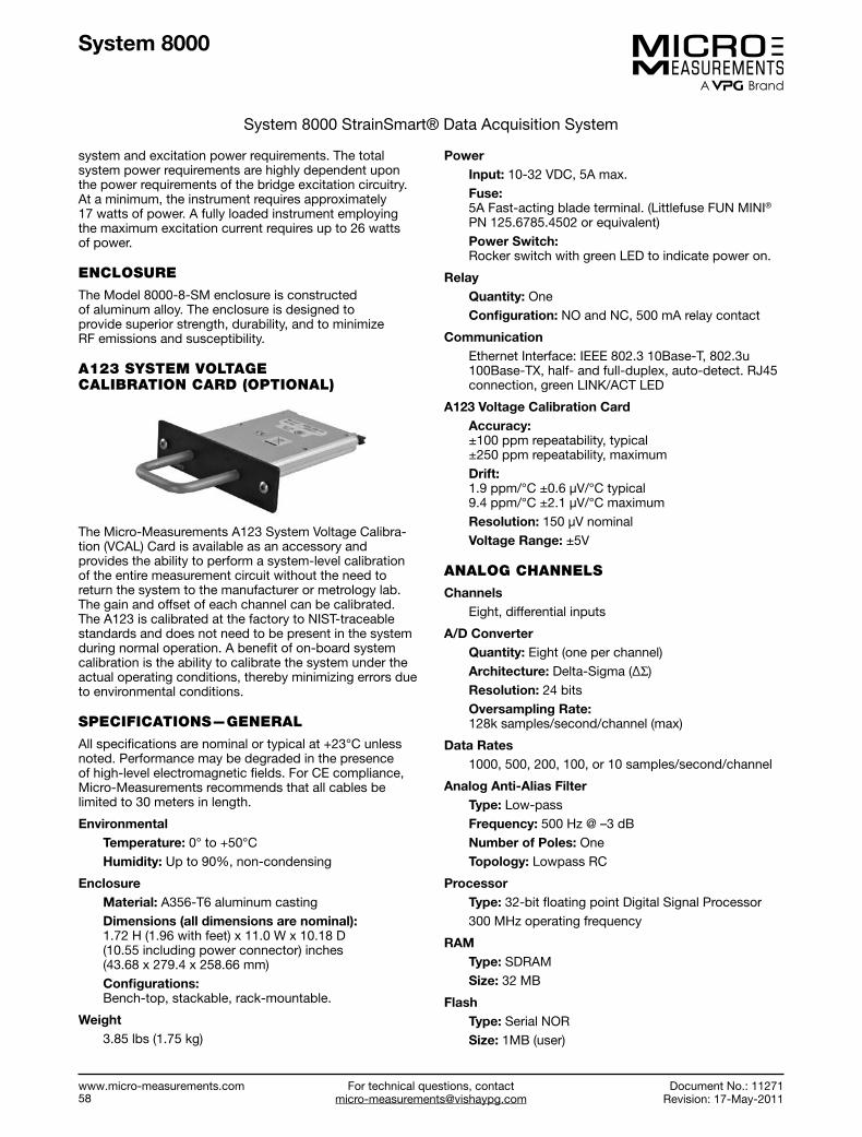
System 8000
System 8000 StrainSmart® Data Acquisition System
system and excitation power requirements. The total system power requirements are highly dependent upon the power requirements of the bridge excitation circuitry. At a minimum, the instrument requires approximately 17 watts of power. A fully loaded instrument employing the maximum excitation current requires up to 26 watts of power.
ENCLOSURE
The Model 8000-8-SM enclosure is constructed of aluminum alloy. The enclosure is designed to provide superior strength, durability, and to minimize RF emissions and susceptibility.
A123 SYSTEM VOLTAGE CALIBRATION CARD (OPTIONAL)
The Micro-Measurements A123 System Voltage Calibra-tion (VCAL) Card is available as an accessory and provides the ability to perform a system-level calibration of the entire measurement circuit without the need to return the system to the manufacturer or metrology lab. The gain and offset of each channel can be calibrated. The A123 is calibrated at the factory to NIST-traceable standards and does not need to be present in the system during normal operation. A benefit of on-board system calibration is the ability to calibrate the system under the actual operating conditions, thereby minimizing errors due to environmental conditions.
SPECIFICATIONS—GENERAL
All specifications are nominal or typical at +23°C unless noted. Performance may be degraded in the presence of high-level electromagnetic fields. For CE compliance, Micro-Measurements recommends that all cables be limited to 30 meters in length.
EnvironmentalTemperature: 0° to +50°CHumidity: Up to 90%, non-condensing
EnclosureMaterial: A356-T6 aluminum castingDimensions (all dimensions are nominal): 1.72 H (1.96 with feet) x 11.0 W x 10.18 D (10.55 including power connector) inches (43.68 x 279.4 x 258.66 mm)Configurations: Bench-top, stackable, rack-mountable.
Weight3.85 lbs (1.75 kg)
PowerInput: 10-32 VDC, 5A max.Fuse: 5A Fast-acting blade terminal. (Littlefuse FUN MINI® PN 125.6785.4502 or equivalent)Power Switch: Rocker switch with green LED to indicate power on.
RelayQuantity: OneConfiguration: NO and NC, 500 mA relay contact
CommunicationEthernet Interface: IEEE 802.3 10Base-T, 802.3u 100Base-TX, half- and full-duplex, auto-detect. RJ45 connection, green LINK/ACT LED
A123 Voltage Calibration CardAccuracy: ±100 ppm repeatability, typical ±250 ppm repeatability, maximumDrift: 1.9 ppm/°C ±0.6 μV/°C typical 9.4 ppm/°C ±2.1 μV/°C maximumResolution: 150 μV nominalVoltage Range: ±5V
ANALOG CHANNELS
Channels Eight, differential inputs
A/D ConverterQuantity: Eight (one per channel)Architecture: Delta-Sigma (ΔΣ)Resolution: 24 bitsOversampling Rate: 128k samples/second/channel (max)
Data Rates1000, 500, 200, 100, or 10 samples/second/channel
Analog Anti-Alias FilterType: Low-passFrequency: 500 Hz @ –3 dBNumber of Poles: OneTopology: Lowpass RC
ProcessorType: 32-bit floating point Digital Signal Processor300 MHz operating frequency
RAMType: SDRAMSize: 32 MB
FlashType: Serial NORSize: 1MB (user)
For technical questions, contact [email protected]
www.micro-measurements.com 58
Document No.: 11271Revision: 17-May-2011

System 8000
System 8000 StrainSmart® Data Acquisition System
Digital FiltersType: Two-stage Finite Impulse Response (FIR)
Table 1. Digital Filter Specifications
fuser (Hz)
fpass (Hz)
Passband Peak-Peak Ripple
(dB)
Stopband Attenuation
(dB)1000 360 0.01 –70500 200 0.01 –80200 80 0.01 –80100 35 0.01 –7010 3.5 0.01 –66
System CalibrationFirmware-controlledCalibration Voltage Supplied by Model A123 voltage calibration cardType: Multi-point, ≥100 samples per point
STRAIN GAGE INPUTS
ChannelsUp to 8 per scanner
InputsSoftware selectable for S+/S-, Vcal+/Vcal-, or excitationStrain Gage 120Ω, 350Ω, 1000Ω quarter-bridges; 60Ω to 5000Ω half- and full-bridgesInput Impedance: 220 MΩ nominal each inputSource Current: ±5 nA per volt excitation
Measurement Range and ResolutionRange: Depends upon excitation setting (see Table 2)Resolution: 0.5 με @ GF=2 (0.25 μV/V)
Table 2— Strain Gage Measurement Range and Resolution
Excitation Volts
Typical Measuring Range includes Imbalance
±με @ GF=2 ±mV/V0 77500* 19*
0.25 310000 1550.5 155000 770.75 103000 51
1 77000 382 38000 193 25000 124 77000 385 62000 316 51000 257 44000 228 38000 199 34000 1710 31000 15
* NOTE: Range calculations at zero volts excitation arebased upon 1 volt excitation, and are typically used for thequantification of self-generating noise.
Input Connector8-pin TIA/EIA RJ45 (MM Part No. A106, Tyco AMPtype 554739 or equivalent)Use of a crimping tool is recommended (MM Part No. A108, Tyco AMP Model No. 3-23-1652-0, or equivalent). Crimping tool can be used on both shielded and non-shielded connectors.
AmplifierZero Temperature Stability: ±1 μV/°C RTI, after 60-minute warm-upDC Gain Accuracy and Stability: ±0.05%; ±50 ppm/°C (1 year without periodic VCAL)Analog Input (including Full-Scale balance):
Low Range: ±38 mVHigh Range: ±155 mVLinearity: ±0.02% of Full ScaleCommon-Mode Rejection: >90 dB (DC to 60 Hz)Common-Mode Voltage Range: ±12V typical
BalanceType: Software (mathematical)Range: Full ADC Range (actual balance level shifts dynamic measurement range 1:1)
ExcitationSelection: Software controlledUnipolar: 0 to +10 VDCResolution: 3 mVAccuracy: ±10 mV typical (Firmware measures excitation variations during arming process)Current: 50 mA max per channel
Over-current limitedOver-current indication
Load Regulation: <0.05% of Full Scale for 10% to 100% of Full Scale loads with remote senseTemperature Stability: ±10 ppm/°C
Quarter-Bridge CompletionSelection: Firmware-controlledAccuracy and drift:
120Ω and 350Ω: ±0.01%, 2.8 ppm/°C max.1 kΩ: ±0.01%, 1.6 ppm/°C max. (Socketed)
Shunt CalibrationSelection: Firmware-controlledConfiguration:
Internal: P– to D120, P– to D350, P– to D1000Sockets: Tin-platedLevels: Simulates 10000 με @ GF = 2.0
For technical questions, contact [email protected]
www.micro-measurements.com 59
Document No.: 11271Revision: 17-May-2011

System 8000
System 8000 StrainSmart® Data Acquisition System
Values:P– to D120: 5940Ω ±0.1%P– to D350: 17325Ω ±0.1%P– to D1000: 49500Ω ±0.1%
THERMOCOUPLE INPUTS
Channels: Up to 8 per scanner
InputsSupported thermocouple types: J, K, T, E, N, R, S, BCold-junction compensation, software-selectableOpen-sensor detectionInput Impedance: 22 MΩ nominal each input
Input ConnectorsEight-pin TIA/EIA RJ45
AmplifierZero Temperature Stability: ±2 μV/°C RTI, ±10 μV/°C RTO, after 60-minute warm-upDC Gain Accuracy and Stability: ±0.1%; ±30 ppm /°CLinearity: ±0.02% of Full ScaleCommon Mode Rejection (DC to 60 Hz): >90 dBCommon Mode Voltage Range: ±12V typical
Measurement Range and ResolutionRange: ±77.5 mVResolution: 1°C minimum
Accuracy±2°C (nominal)
HIGH-LEVEL INPUT
ChannelsUp to 8 per scanner
InputsDifferentialInput Impedance: 220 MΩ nominal each inputInput Bias Current: ±0.5 nA typical (±2 nA max.)
Input Connector8-pin TIA/EIA RJ45 (MM Part No. A106, Tyco AMPtype 554739 or equivalent)Use of a crimping tool is recommended (MM Part No. A108, Tyco AMP Model No. 3-23-1652-0, or equivalent). Crimping tool can be used on both shielded and non-shielded connectors.
AmplifierZero Temperature Stability: ±2 μV/°C RTI, typical, ±10 μV/°C RTO, after 60-minute warm-upDC Gain Accuracy and Stability: ±0.1%; ±30 ppm /°CLinearity: ±0.02% of Full ScaleCommon-Mode Rejection (DC to 60 Hz): >90 dBCommon-Mode Voltage Range: ±12V typical
Measurement Ranges and ResolutionRange: ±10VResolution: 100 μV effective
ExcitationSelection: Software controlledUnipolar Mode:
Range: 0 to +11.997 VDCAccuracy: ±10 mV typicalCurrent: 50 mA max. Over-current/over-temperature protectedLoad Regulation: <0.05% of Full Scale (unipolar mode) for a load variation of 10% to 100% of Full Scale loads (with remote sense)Temperature Stability: Better than ±30 ppm/°C
Bipolar Mode:Range: ±12 VDC (24 VDC total)Accuracy: ±5% of Full Scale
For technical questions, contact [email protected]
www.micro-measurements.com 60
Document No.: 11271Revision: 17-May-2011
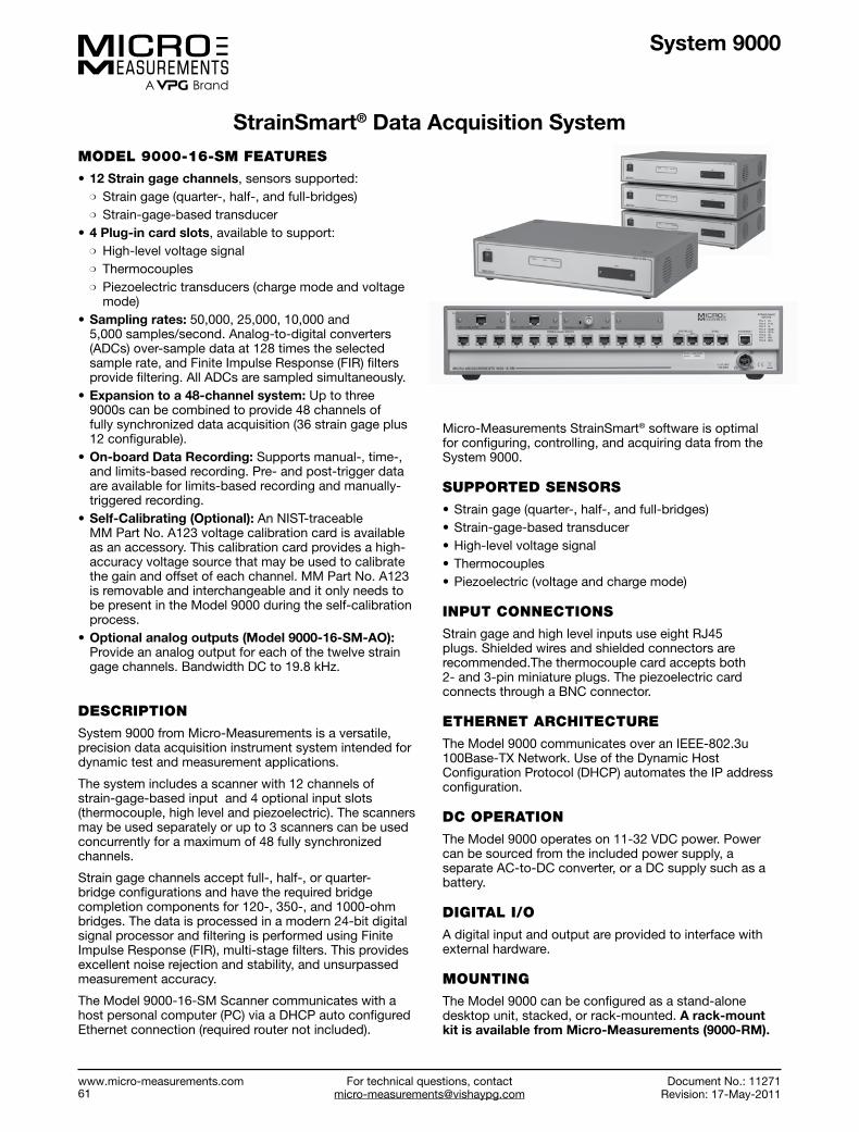
System 9000
StrainSmart® Data Acquisition SystemMODEL 9000-16-SM FEATURES
• 12 Strain gage channels, sensors supported:❍ Strain gage (quarter-, half-, and full-bridges)❍ Strain-gage-based transducer
• 4 Plug-in card slots, available to support:❍ High-level voltage signal❍ Thermocouples❍ Piezoelectric transducers (charge mode and voltage
mode)• Sampling rates: 50,000, 25,000, 10,000 and
5,000 samples/second. Analog-to-digital converters(ADCs) over-sample data at 128 times the selectedsample rate, and Finite Impulse Response (FIR) filtersprovide filtering. All ADCs are sampled simultaneously.
• Expansion to a 48-channel system: Up to three9000s can be combined to provide 48 channels offully synchronized data acquisition (36 strain gage plus12 configurable).
• On-board Data Recording: Supports manual-, time-,and limits-based recording. Pre- and post-trigger dataare available for limits-based recording and manually-triggered recording.
• Self-Calibrating (Optional): An NIST-traceableMM Part No. A123 voltage calibration card is availableas an accessory. This calibration card provides a high-accuracy voltage source that may be used to calibratethe gain and offset of each channel. MM Part No. A123is removable and interchangeable and it only needs tobe present in the Model 9000 during the self-calibrationprocess.
• Optional analog outputs (Model 9000-16-SM-AO):Provide an analog output for each of the twelve straingage channels. Bandwidth DC to 19.8 kHz.
DESCRIPTION
System 9000 from Micro-Measurements is a versatile, precision data acquisition instrument system intended for dynamic test and measurement applications.
The system includes a scanner with 12 channels of strain-gage-based input and 4 optional input slots (thermocouple, high level and piezoelectric). The scanners may be used separately or up to 3 scanners can be used concurrently for a maximum of 48 fully synchronized channels.
Strain gage channels accept full-, half-, or quarter-bridge configurations and have the required bridge completion components for 120-, 350-, and 1000-ohm bridges. The data is processed in a modern 24-bit digital signal processor and filtering is performed using Finite Impulse Response (FIR), multi-stage filters. This provides excellent noise rejection and stability, and unsurpassed measurement accuracy.
The Model 9000-16-SM Scanner communicates with a host personal computer (PC) via a DHCP auto configured Ethernet connection (required router not included).
StrainSmart® Data Acquisition System
Micro-Measurements StrainSmart® software is optimal for configuring, controlling, and acquiring data from the System 9000.
SUPPORTED SENSORS
• Strain gage (quarter-, half-, and full-bridges)• Strain-gage-based transducer• High-level voltage signal• Thermocouples• Piezoelectric (voltage and charge mode)
INPUT CONNECTIONS
Strain gage and high level inputs use eight RJ45 plugs. Shielded wires and shielded connectors are recommended.The thermocouple card accepts both 2- and 3-pin miniature plugs. The piezoelectric cardconnects through a BNC connector.
ETHERNET ARCHITECTURE
The Model 9000 communicates over an IEEE-802.3u 100Base-TX Network. Use of the Dynamic Host Configuration Protocol (DHCP) automates the IP address configuration.
DC OPERATION
The Model 9000 operates on 11-32 VDC power. Power can be sourced from the included power supply, a separate AC-to-DC converter, or a DC supply such as a battery.
DIGITAL I/O
A digital input and output are provided to interface with external hardware.
MOUNTING
The Model 9000 can be configured as a stand-alone desktop unit, stacked, or rack-mounted. A rack-mount kit is available from Micro-Measurements (9000-RM).
For technical questions, contact [email protected]
www.micro-measurements.com 61
Document No.: 11271Revision: 17-May-2011

System 9000
StrainSmart® Data Acquisition System
SPECIFICATIONS
GeneralEnvironmental:
Temperature: 0° to +50°CHumidity: Up to 90%, non-condensing
Enclosure:Material: A356-T6 aluminum castingDimensions: 3.50 H (3.88 with feet) x 17.19 W x 11.50 D (12.97 including optional 9000-SM-VC card and input cards) inches (88.9 x 436.7 x 292.1 mm)Configurations: Bench-top, stackable, rack-mountable
Weight:13.05 lbs (5.92 kg), without auxiliary plug in cards
PowerInput: 11-32 VDC, 10 A maxFuse: 10 A Fast-acting blade terminal. (Littlefuse MINI® Blade fuse P/N 0297010 or equivalent)
CommunicationEthernet interface: 100 MbitNetwork protocol: DHCP
Data RecordingStorage type: Internal SATA solid state driveCapacity: ≥16 GB, max file size is 2 GB
SynchronizationChannel count: ≤48 channels ( 3 devices)Configuration: “Star” topology, max cable length ≤7 ft (~2 m)
ANALOG CHANNELS
Channels 12 Differential inputs 4 Configurable input slots
A/D ConverterArchitecture: Delta-Sigma (ΔΣ)Resolution: 24 bitsOversampling rate: 128 times the selected data rateSampling mode: Simultaneous
Data Rates50,000, 25,000, 10,000 and 5,000 samples/second/channel
Analog Anti-Alias FilterType: Low-passFrequency: 20 kHz @ –3 dBNumber of poles: OneTopology: Lowpass RC
Digital FiltersType: Finite Impulse response (FIR), two selectable filters provided per sampling rate)
Table 1. Default Digital Filter Specifications
fuser (Hz)
fpass (Hz)
Passband Peak-Peak Ripple
(dB)
Stopband Attenuation
(dB)50,000 12500 0.01 –8025,000 6250 0.01 –8010,000 2500 0.01 –805,000 1250 0.01 –80
Table 2. Alternate Digital Filter Specifications
fuser (Hz)
fpass (Hz)
Passband Peak-Peak Ripple
(dB)
Stopband Attenuation
(dB)50,000 6250 0.01 –8025,000 3125 0.01 –8010,000 1250 0.01 –805,000 625 0.01 –80
STRAIN GAGE INPUTS
ChannelsQuantity: 12
InputsSoftware-selectable for S+/S–, Vcal+/Vcal–, or excitationStrain gage: 120 Ω, 350 Ω, 1000 Ω quarter-bridges; 60 Ω to 5000 Ω half- and full-bridgesInput impedance: 220 MΩ nominal each inputSource current: ±5 nA per volt excitation
Measurement Range and ResolutionRange: Depends upon excitation setting (see Table 3)Resolution: 0.5 με @ GF=2 (0.25 μV/V)
Table 3. Strain Gage Measurement Range and Resolution
Excitation Volts
Typical Measuring Range includes Imbalance
±με @ GF=2 ±mV/V0 77500* 19*
0.25 310000 1550.5 155000 770.75 103000 51
1 77000 382 38000 193 25000 124 77000 385 62000 316 51000 257 44000 228 38000 199 34000 1710 31000 15
* NOTE: Range calculations at zero volts excitation arebased upon 1 volt excitation, and are typically used for thequantification of self-generating noise.
StrainSmart® Data Acquisition System
For technical questions, contact [email protected]
www.micro-measurements.com 62
Document No.: 11271Revision: 17-May-2011

System 9000
StrainSmart® Data Acquisition System
Input Connector8-pin shielded TIA/EIA RJ45 (MM Part No. A114)
AmplifierZero temperature stability: ±1 μV/°C RTI, after 60-minute warm-upDC Gain accuracy and stability: ±0.05%; ±50 ppm/°C (1 year without periodic VCAL)Analog input (including full-scale balance):
Low range: ±38 mVHigh range: ±155 mV
Linearity: ±0.02% of full scaleCommon-mode rejection: >90 dB (DC to 60 Hz)Common-mode voltage range: ±12 V typical
BalanceType: Software (mathematical)Range: Full ADC range (actual balance level shifts dynamic measurement range 1:1)
ExcitationSelection: Software controlledUnipolar: 0 to +10 VDCResolution: 3 mVAccuracy: ±10 mV typical (Firmware measures excitation variations during arming process)Current: 50 mA max per channelOver-current limitedOver-current indicationLoad regulation: <0.05% of full scale for 10% to 100% of full scale loads with remote senseTemperature stability: ±10 ppm/°C
Quarter-Bridge CompletionSelection: Firmware controlledAccuracy and drift:
120 Ω and 350 Ω: ±0.01%, 5 ppm/°C max1 kΩ: ±0.01%, 4.5 ppm/°C max (socketed)
Shunt CalibrationSelection: Firmware controlledConfiguration:
Internal QB: P– to D120, P– to D350, P– to D1000
External: Switched shunt at input connector (Ra, Rb)Standard factory installed resistor values: Simulates 10000 με @ GF = 2.0
5940 Ω ±0.1%: Shunts P– to D120
17325 Ω ±0.1%: Shunts P– to D350
49500 Ω ±0.1%: Shunts P– to D1000
17325 Ω ±0.1%: External shunt Ra to RbResistor sockets: Tin-plated
9000-TC THERMOCOUPLE INPUT CARD (OPTIONAL)
Channels: Quantity: 1 per card; 4 cards max
InputsSupported thermocouple types: J, K, T, E, N, R, S, BCold-junction compensation, software-selectableOpen-sensor detectionInput impedance: 22 MΩ nominal each input
Input ConnectorsMini-TC with optional earth connection
AmplifierZero temperature stability: ±2 μV/°C RTI, ±10 μV/°C RTO, after 60-minute warm-upDC Gain accuracy and stability: ±0.1%; ±30 ppm /°CZero accuracy and linearity: ±0.02% of full scaleCommon mode rejection (DC to 60 Hz): >90 dBCommon mode voltage range: ±12 V typical
Measurement Range and ResolutionRange: ±77.5 mVResolution: 1°C min
Measurement Accuracy±2°C (nominal)
9000-HL HIGH-LEVEL INPUT CARD (OPTIONAL)
ChannelsQuantity: 1 per card; 4 cards max
InputsDifferentialInput impedance: 220 MΩ nominal each inputInput bias current: ±0.5 nA typical (±2 nA max)
Input Connector8-pin shielded TIA/EIA RJ45 (MM Part No. A114)
AmplifierZero temperature stability: ±2 μV/°C RTI, typical, ±10 μV/°C RTO, after 60-minute warm-upDC Gain accuracy and stability: ±0.1%; ±30 ppm /°CZero accuracy and linearity: ±0.02% of full scaleCommon-mode rejection (DC to 60 Hz): >90 dBCommon-mode voltage range: ±12 V typical
StrainSmart® Data Acquisition System
For technical questions, contact [email protected]
www.micro-measurements.com 63
Document No.: 11271Revision: 17-May-2011
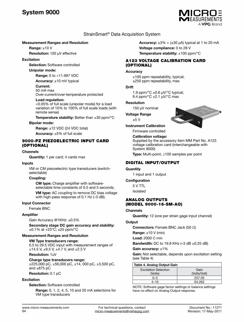
System 9000
StrainSmart® Data Acquisition System
Measurement Ranges and ResolutionRange: ±10 VResolution: 100 μV effective
ExcitationSelection: Software controlledUnipolar mode:
Range: 0 to +11.997 VDCAccuracy: ±10 mV typicalCurrent: 50 mA max Over-current/over-temperature protectedLoad regulation: <0.05% of full scale (unipolar mode) for a load variation of 10% to 100% of full scale loads (with remote sense)Temperature stability: Better than ±30 ppm/°C
Bipolar mode:Range: ±12 VDC (24 VDC total)Accuracy: ±5% of full scale
9000-PZ PIEZOELECTRIC INPUT CARD (OPTIONAL)
ChannelsQuantity: 1 per card; 4 cards max
InputsVM or CM piezoelectric type transducers (switch-selectable)Coupling:
CM type: Charge amplifier with software-selectable time constants of 0.5 and 5 seconds. VM type: AC coupling to remove DC bias voltage with high-pass response of 0.1 Hz (–3 dB).
Input ConnectorFemale BNC
AmplifierGain Accuracy @1KHz: ±0.5% Secondary stage DC gain accuracy and stability: ±0.1% at +23°C; ±25 ppm/°C
Measurement Ranges and ResolutionVM Type transducers range: 0.5 to 29.5 VDC input with measurement ranges of ±14.5 V, ±9.5 V, ±4.7 V, and ±2.3 VResolution: 1uVCharge type transducers range: ±225,000 pC, ±56,000 pC, ±14, 000 pC, ±3,500 pC, and ±875 pC Resolution: 0.1 pC
ExcitationSelection: Software controlled
Range: 0, 1, 2, 4, 5, 10 and 20 mA selections for VM type transducers
Accuracy: ±3% + (±30 μA) typical at 1 to 20 mAVoltage compliance: 0 to 28 VTemperature stability: ±100 ppm/°C
A123 VOLTAGE CALIBRATION CARD (OPTIONAL)
Accuracy±100 ppm repeatability, typical; ±250 ppm repeatability, max
Drift1.9 ppm/°C ±0.6 μV/°C typical; 9.4 ppm/°C ±2.1 μV/°C max
Resolution 150 μV nominal
Voltage Range ±5 V
Instrument CalibrationFirmware controlledCalibration voltage: Supplied by the accessory item MM Part No. A123 voltage calibration card (interchangeable with System 8000)Type: Multi-point, ≥100 samples per point
DIGITAL INPUT/OUTPUT
Quantity1 input and 1 output
Configuration5 V TTLIsolated
ANALOG OUTPUTS (MODEL 9000-16-SM-AO)
ChannelsQuantity: 12 (one per strain gage input channel)
OutputConnectors: Female BNC Jack (50 Ω)Range: ±10 V (min) Load: 2000 Ω min Bandwidth: DC to 19.8 KHz (–3 dB ±0.25 dB) Gain accuracy: ±1% Gain: Not selectable, depends upon excitation setting (see Table 4)
Table 4. Analog Output GainExcitation Selection
(Volts)Gain
(Volts/Volt)0–3 257.054–10 64.262
NOTE: Software gage factor settings or balance settings have no effect on Analog Output response.
StrainSmart® Data Acquisition System
For technical questions, contact [email protected]
www.micro-measurements.com 64
Document No.: 11271Revision: 17-May-2011
For technical questions, [email protected]
www.micro-measurements.com57
Special-Purpose Instruments
Model 1300 ........................................... 66
Model 700 ............................................. 68
RS-200 .................................................. 70

For technical questions, contact [email protected]
Micro-Measurements
www.micro-measurements.com 66
FEATURES
• A compact, battery-powered instrument used toverify the electrical quality of a strain gage installationBEFORE it is placed in service
• Reads with the push of a button—no warm-up• Reads insulation resistance (leakage) to 20,000
megohms with 15 VDC• Measures deviation of installed gage resistance from
precise standards to a resolution of 0.02%• Ohmmeter scale for troubleshooting questionable
installations• Verifies the complete gage circuit, including leadwires
DESCRIPTION
Two of the most important measurements used to verify the quality of a strain gage installation are insulation resistance (leakage to ground) and shift in gage resistance due to installation procedures. While these two measurements are not a complete guarantee of eventual proper strain gage performance, any installation that produces questionable values should not be relied upon where accuracy of results is necessary.
For example, a voltage difference between the specimen and strain gage frequently exists. A low insulation resistance will permit this voltage differential to introduce extraneous signals during strain measurement.
Several sources of variations in insulation resistance and shifts in gage resistance are:
• Insulation resistance in excess of 20,000 megohmsshould be expected for foil strain gages when installedunder laboratory conditions. A value of 10,000megohms should be considered minimum. A readingbelow this value generally indicates trapped foreignmatter, moisture, residual flux or backing damage dueto soldering, as well as incomplete solvent evaporationfrom an overcoating.
• Deterioration of the insulation resistance with time maybe an indication of an improperly coated installation.
• At higher test temperatures, particularly above +300°F[+150°C], it is normal to expect lesser values. Tenmegohms is considered to be the lower allowable value.
• Shifts in gage resistance during installation should notnormally exceed 0.5% when using room-temperature-curing adhesives. Resistance shifts greater than 0.5%generally indicate damage to the gage due to improperhandling or clamping. However, strain gages installedusing elevated-temperature-curing adhesives mayexhibit greater shifts in resistance due to adhesivelock-up at elevated temperatures (difference in linearcoefficient of thermal expansion between the straingage and specimen). These shifts will vary dependingupon the specific cure temperature and materials used.The shifts should never exceed 2% and should beuniform within 0.5%.
SPECIFICATIONS
INPUT CIRCUITSGages: Three-wire quarter bridge (120Ω and 350Ω) and half bridge. Other value quarter bridges using customer’s reference, at readily accessible panel terminals.As ohmmeter: Two leads (500Ω and 500 MΩ mid-scale)
INPUT LEADS4-ft [1.2m] 4-conductor AWG #26 [0.4-mm diameter]twisted Teflon®-insulated cable supplied (with groundclip and three tinned leads)
METER3.5-in size (3.00-in [76-mm] scale length) with mirrorTracking accuracy ±1% full range
MODE SWITCHFive momentary push buttons: battery check, ±5% deviation, ±1% deviation, gage resistance (ohms), and insulation resistance (megohms)
DEVIATION MODETwo ranges, ±1% and ±5%, F.S. (50 graduations either side of zero)Accuracy:
1% range: 0.04% ΔR (2 meter graduations) 5% range: 0.2% ΔR (2 meter graduations)
Excitation: 1.0 VDC per gage
INSULATION RESISTANCE MODEGraduated 5 MΩ to 20,000 MΩ (500 MΩ mid-scale)Accuracy: 1 scale divisionTest Voltage: 15 VDC open circuit
Model 1300
Gage Installation Tester
Document No.: 11301Revision: 17-May-2011

For technical questions, [email protected]
Micro-Measurements
Document No.: 11301Revision: 17-May-2011
www.micro-measurements.com 67
Model 1300
Gage Installation Tester
OHM MODEGraduated 5Ω to 20 kΩ (500Ω mid-scale)Accuracy: 1 scale divisionTest Voltage: 2 VDC open circuit (0.4 VDC @ 120Ω)
ENVIRONMENTAL+15°F to +125°F [–10°C to +50°C]; up to 80% relativehumidity, non-condensing
SIZEAluminum case (separable lid) 5 H x 7 W x 5 D in with lid [125 x 180 x 126 mm]
WEIGHT3.6 lb [1.6 kg] with batteries
POWER SUPPLYFour 9V NEDA 1604 batteries (Eveready® 216 or equivalent) Life: Will fully test 1000–5000 installation.
All specifications are nominal or typical @ +23°C unless noted.
Teflon is a Registered Trademark of DuPont
Eveready is a Registered Trademark of Eveready Battery Co Inc.
Model 1300
Document No.: 11301Revision: 17-May-2011

For technical questions, contact [email protected]
Micro-Measurements
www.micro-measurements.com 68
FEATURES
• Separate visual and audible indicators monitor welderstatus. Weld energy is continuously adjustable from3 to 50 joules, making the Model 700 an excellentchoice for installing weldable strain gages andtemperature sensors, as well as small thermocouplesand light-gauge metal.
• Supplied with a lightweight soldering pencil. A front-panel control adjusts soldering tip temperature for awide range of soldering applications in the field or in thelaboratory.
• “Low-battery” light to warn the user when the internal,sealed lead-acid battery requires charging. A batterycharger is included to provide for full battery chargewith no danger of overcharging. Indicator lights monitorbattery charge rate.
• Convenient storage space for cables, battery chargerand instruction manual
GENERAL SPECIFICATIONS
OVERALL SIZE9 L x 9 W x 9-3/4 H in [230 x 230 x 250 mm]
WEIGHT21 lb [9.5 kg]
POWER FOR RECHARGING115 VAC or 230 VAC, 50-60 Hz. Uses external AC transformer (provided)
OPERATING AND STORAGE TEMPERATURE RANGE0°F to +120°F [–20°C to +50°C]
WELDING SPECIFICATIONS
WELD ENERGY RANGE3 to 50 joules, continuously adjustable by front-panel controlMaximum open-circuit voltage less than 25 VDC
MAXIMUM WELD REPETITION RATE20 per minute at 30 joules, typical
NUMBER OF WELDS PER BATTERY CHARGEApproximately 2000 at weld energy setting of 30 joules. This is equivalent to 40 Micro-Measurements weldable gage installations.
BATTERY CHARGE TIME: (FROM FULL DISCHARGE)12 hours to 75% full charge; 18 hours to full charge
BATTERYOne sealed, rechargeable lead-acid (non-liquid) type, 12 volt, 5 ampere-hour
WELDING PROBEManually fired with trigger control and “steady-rest”
WELDING CABLESTwo 5 ft [1.5m], fully flexible
WELD ENERGY MONITORCalibrated front-panel control with READY and WAIT indicators; audible indication selectable
Model 700
Portable Strain Gage Welding and Soldering Unit
Document No.: 11302Revision: 17-May-2011

For technical questions, [email protected]
Micro-Measurements
Document No.: 11302Revision: 17-May-2011
www.micro-measurements.com 69
Model 700
Portable Strain Gage Welding and Soldering Unit
Document No.: 11302Revision: 17-May-2011
SOLDERING SPECIFICATIONS
TEMPERATURE CONTROLContinuously variable with bands indicating melting range of solders
SOLDERING PENCIL1.1 oz [31 gm], rated at 25 watts, 12 volt operation. Tip temperature adjustable from +200°F to +900°F [+90°C to +480°C].
SOLDERING DURATION4 hours using +361°F [+183°C] melting point solders (with initial full charge)
ACCESSORYModel 700-A103 Spot Welding Probe Set: Recommended for spot welding instrument leadwires to ZC Series high-temperature gage ribbons
PANEL CONTROL FEATURES
SELECTOR SWITCH FOR WELDING/SOLDERING
WELD ENERGYCONTROL
16 VACPOWER
CABLE STORAGE AREA
BATTERY STATUS INDICATOR LIGHTS
SOLDERINGPENCIL RECEPTACLE
SOLDERING PENCIL HEAT CONTROL
AUDIO INDICATOR SWITCH
All specifications are nominal or typical at +23°C unless noted.
Model 700
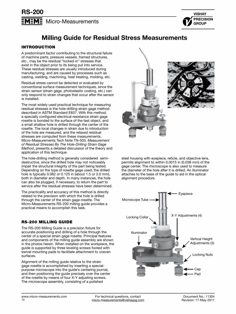
For technical questions, contact [email protected]
Micro-Measurements
www.micro-measurements.com 70
INTRODUCTION
A predominant factor contributing to the structural failure of machine parts, pressure vessels, framed structures, etc., may be the residual “locked-in” stresses that exist in the object prior to its being put into service. These residual stresses are usually introduced during manufacturing, and are caused by processes such as casting, welding, machining, heat treating, molding, etc.
Residual stress cannot be detected or evaluated by conventional surface measurement techniques, since the strain sensor (strain gage, photoelastic coating, etc.) can only respond to strain changes that occur after the sensor is installed.
The most widely used practical technique for measuring residual stresses is the hole-drilling strain gage method described in ASTM Standard E837. With this method, a specially configured electrical resistance strain gage rosette is bonded to the surface of the test object, and a small shallow hole is drilled through the center of the rosette. The local changes in strain due to introduction of the hole are measured, and the relaxed residual stresses are computed from these measurements. Micro-Measurements Tech Note TN-503, Measurement of Residual Stresses By The Hole-Drilling Strain Gage Method, presents a detailed discussion of the theory and application of this technique.
The hole-drilling method is generally considered semi-destructive, since the drilled hole may not noticeably impair the structural integrity of the part being tested. Depending on the type of rosette gage used, the drilled hole is typically 0.062 or 0.125 in (about 1.5 or 3.0 mm), both in diameter and depth. In many instances, the hole can also be plugged, if necessary, to return the part to service after the residual stresses have been determined.
The practicality and accuracy of this method is directly related to the precision with which the hole is drilled through the center of the strain gage rosette. The Micro-Measurements RS-200 milling guide provides a practical means to accomplish this task.
RS-200 MILLING GUIDE
The RS-200 Milling Guide is a precision fixture for accurate positioning and drilling of a hole through the center of a special strain gage rosette. Principal features and components of the milling guide assembly are shown in the photos herein. When installed on the workpiece, the guide is supported by three leveling screws footed with swivel mounting pads to facilitate attachment to uneven surfaces.
Alignment of the milling guide relative to the strain gage rosette is accomplished by inserting a special-purpose microscope into the guide’s centering journal, and then positioning the guide precisely over the center of the rosette by means of four X-Y adjusting screws. The microscope assembly, consisting of a polished
steel housing with eyepiece, reticle, and objective lens, permits alignment to within 0.0015 in (0.038 mm) of the gage center. The microscope is also used to measure the diameter of the hole after it is drilled. An illuminator attaches to the base of the guide to aid in the optical alignment procedure.
Eyepiece
Microscope Tube
Locking Collar X-Y Adjustments (4)
Vertical HeightAdjustments (3)
Locking Nuts
CapPad
Illuminator
RS-200
Milling Guide for Residual Stress Measurements
Document No.: 11304Revision: 17-May-2011

For technical questions, [email protected]
Micro-Measurements
Document No.: 11304Revision: 17-May-2011
www.micro-measurements.com 71
RS-200
Milling Guide for Residual Stress Measurements
Document No.: 11304Revision: 17-May-2011
After alignment, the microscope is removed from the guide, and the milling bar or high-speed air turbine is inserted in its place. The milling bar is used for slow-speed drilling of the hole. Two standard milling cutters are supplied: 0.062 and 0.125 in (1.6 and 3.2 mm) diameter. The milling bar is equipped with a universal joint for flexible connection to a drill motor.
Milling Bar withUniversal JointAttached
MicrometerAdjustment
Locking Collar
MicrometerLock
Micrometer
Mill
Conventional slow-speed milling may be satisfactory on some mild steels and aluminum alloys. But high-speed drilling is generally the most convenient and practical method for introducing the hole in all test materials. (When residual stresses are to be measured on materials such as stainless steels, nickel-based alloys, etc., ultra high-speed drilling techniques are preferred.) For this purpose, a high-speed air-turbine assembly, along with a supply of tungsten carbide-tipped cutters [ten
each 0.031 in (0.8 mm) diameter and 0.062 in (1.6 mm) diameter], is supplied with the milling guide. A foot pedal control is included for operating the air turbine.
Air TurbneAssembly
Grooved NylonCollar
Anti-RotationRing Adapter
CarbideCutter
Basic RS-200Milling Guide
To Air Supply
Spring Assembly
Mount
A micrometer depth set attachment, available in English or metric units, is provided with each milling guide assembly. This device is used for incremental drilling when information on the variation of residual-stress-with-depth is desired.
Other items supplied include a plastic template for the proper location of the milling guide foot pads on the test part and a special break-off tool used to remove the foot pads from the part after the test is completed. All components are housed in a sturdy carrying case. The guide is approximately 9 in (230 mm) high, and 4.5 in (114 mm) wide at the base.
A fast-setting-cement kit, used to firmly attach the guide to the test part, is available as an accessory item.
RS-200

Data Book
Strain Gage InstrumentationMicro-Measurementswww.micro-measurements.com
Where the World Goes for Precision Measurement and Control
www.vishaypg.com
VMM-DB0107-1106
© Copyright 2011 Vishay Precision Group. ® Registered trademarks of Vishay Precision Group. All rights reserved. Printed in USA. Specifications subject to change without notice.
mandy.jansz
ANZ Supplier