Storage Batteries Lead-Acid Type Requirements and...
48
‘AT&T PRACTICE Stclmkucl AT&T 1$7-60~ -701 Issue 19, August J985 STORAGE BATi%RIES LEAD-ACID TYPE”” “ ““;. REQUIREMENTS AND PROCEDURES .4. , .! ., CONTENTS PAGE 3. 4. CONTENTS PAGE H. Battery Connections and Genemd Main- tenance . . . . . . . . ..23 I. GENERAL . . . . . . . . ...2 .. A. introduction . . . . . . . . . 2 Manufacturers’ Identtfimtion and Serial Numbers . . . . . . . . . .1O APPARATUS, . . . . . . . . ..25 B. PROCEDURES . . . . . . . . ..27 .%ty . . . . . ..’ . . ..l3 First Aid . . . . . . . . . .13 Battery Records . . . . . . . 27 .> Battery Measurements . . . . . 27 c. D. E. F. G. A. B. c. Neutralizing Agents . . . . . . 14 Explosion and Fire Prevention . . . 15 Battery Charging . . . . . . . 16 Field Repairs . . . . . . . . 16 Lead-Sulfate Crystals . . . . . . 33 ,. . Battery Charging . . . . . . . 35 CeHRevursa . . . . . . . . 36 BaWery Electrolyte . . . . . . . 37 Battery Oischarge Capacity Tests and o. E. F. G. H. 1. Index of lead-Acid Batwy Require- nients and Procedures . . . . . 17 Replacement Criteria . . . . . . 39 Batterv Connections and General Main- J. Recommended Maintenance Intervals . . . . . . . . . . . . . “17 H. terianle ”....... . ..43 2. REQUIREMENTS . . . . . . . . . 17 Figures 1. 2. 3. 4. ‘5. Battery Records . . . . . . . 17 A. Typical Charge Curves for a Fully Ois- Battery Measurements . . . . . 17 B. charged lead-calcium Battery . . . . 22 Rubber Battery Jar Electrolyte Level indica- toc Flaats . . . . . . . . . . . 24 c. Leod-Sulfate Crystals . . . . . . 17 . .- D. Battery Charging . . . . . . . 21 Form E-2003 Storage 8aWery Record . . 28 Form E-359 1 Storage Battery Record . . 29 Form E-3593 Storage Battery Record—lndi- E. .- Cell Reversals . . . . . . . .21 Battery Electrolyte . . . . . . . 22 F. 2 G. Battery Okcharge Capacity Tests and Replacement Criteria . . . . . . 23 vidual Cell Voltages . . . . . . . 30 ( ‘I)ljvrigtli “]!)s5 AT&T Twhnol(,~iws A II Rights Rwerwl Printed in U.S.A. Page 1
Transcript of Storage Batteries Lead-Acid Type Requirements and...

‘AT&T PRACTICE
Stclmkucl
AT&T 1$7-60~ -701
Issue 19, August J985
STORAGE BATi%RIES
LEAD-ACID TYPE”” “ ““;.
REQUIREMENTS AND PROCEDURES
.4.
,.!
., CONTENTS PAGE
3.
4.
CONTENTS PAGE
H. Battery Connections and Genemd Main-
tenance . . . . . . . . ..23
I. GENERAL . . . . . . . . ...2. .
A. introduction . . . . . . . . . 2
Manufacturers’ Identtfimtion and Serial
Numbers . . . . . . . . . .1O
APPARATUS, . . . . . . . . ..25B.
PROCEDURES . . . . . . . . ..27
.%ty . . . . . ..’ . . ..l3
First Aid . . . . . . . . . .13
Battery Records . . . . . . . 27.>
Battery Measurements . . . . . 27
c.
D.
E.
F.
G.
A.
B.
c.Neutralizing Agents . . . . . . 14
Explosion and Fire Prevention . . . 15
Battery Charging . . . . . . . 16
Field Repairs . . . . . . . . 16
Lead-Sulfate Crystals . . . . . . 33,. .
Battery Charging . . . . . . . 35
CeHRevursa . . . . . . . . 36
BaWery Electrolyte . . . . . . . 37
Battery Oischarge Capacity Tests and
o.
E.
F.
G.
H.
1. Index of lead-Acid Batwy Require-
nients and Procedures . . . . . 17
Replacement Criteria . . . . . . 39
Batterv Connections and General Main-
J. Recommended Maintenance Intervals
. . . . . . . . . . . . . “17 H.
terianle ”....... . ..432. REQUIREMENTS . . . . . . . . . 17
Figures
1.
2.
3.
4.
‘5.
Battery Records . . . . . . . 17A.
Typical Charge Curves for a Fully Ois-Battery Measurements . . . . . 17B.
charged lead-calcium Battery . . . . 22
Rubber Battery Jar Electrolyte Level indica-
toc Flaats . . . . . . . . . . . 24
c. Leod-Sulfate Crystals . . . . . . 17
..- D. Battery Charging . . . . . . . 21
Form E-2003 Storage 8aWery Record . . 28
Form E-359 1 Storage Battery Record . . 29
Form E-3593 Storage Battery Record—lndi-
E..-
Cell Reversals . . . . . . . .21
Battery Electrolyte . . . . . . . 22F.
2
G. Battery Okcharge Capacity Tests and
Replacement Criteria . . . . . . 23 vidual Cell Voltages . . . . . . . 30
( ‘I)ljvrigtli “]!)s5 AT&T Twhnol(,~iws
A II Rights Rwerwl
Printed in U.S.A. Page 1

AT4T 1s741-701
6.
7.
8.
9.
10.
11.
Tables
A.
B.
c.
D.
E.
F.
G.
H.
1.
J.
K.
,~
CONTENTS PA*,.
Typical Rectangukr till Showing Possible
location of Lead-%lfato CryWahen PesitiieElements . . . . . .,,, ~,,,, . .. . ..,
Suggested 5-Hour Rate Battery Discharge
Capacity Test Record Farm . . . . .
Suggested S,ngkCe}l Diiharge Capacity
Record Farm . . . . ...’? ‘...,
Correcting Capacity for Temperature
(Based on 5-Hour Dmharge Rate) . .
Typical Temporary Switch Connected to
Remove Arc Hazard . . . . . . .
8attery Post Seals (Typical) . . . . .
Battery Discharge Rate and Specific Gravity
Range, . ...<.... . .
Grid Material and Nominal. S@fic ~avity
for KS-Coded Lead-Acid -k . . . .
Battery Anticipated life on Float Charge at
77 IF . . . . . . . . . . . .
8attery Electrolyte Level . . . . . .
b,.Cell Float Voltage and Specific Gravity Re-
quirement Chart . . . . . . . .
Index of Lead-Acid Battery Requirements
and Procedures . . . . . . . . .
Recommended Maintenance Intervals .
Freezing Temperature ‘of lbad-Acid 8attery
Electrolyte . . . . . . . . . .
Expected” Resewe of KS-5562 Tank Cells at
600 Amperes D-barge . . . . . .
Battery BoostCharge Time . . , . .
Maximum Allowable Impurities in Battery
Water . . . . . . . . . . . .
34
41
42
43
43
46
4
8
9
10
12
18
19
23
2s
35
38
,.
1. GENRRAL,, , ,, ., .:’
A. lnt@uctian
1.01 This practice covers the apparatus require-ments and adjusting procedures common to
rectangular type lead-acid cells used in batterypqwer plants. $The requiremea~s and procedures inthis practice also apply generally to lead-acid batter-ies used for engine-starting applications.~
1.02 Revision arrows are used to emphasize themore significant changes. This practice is reis-
sued for the. following reasons ...
(a) To rate the KS-5361, L1OO,KS-5553, L503 andL505; KS-5562, and KS-15544, L503 and L505;
and KS-15577 as Mfr Disc. in Table A
(b) To update the manufacturers’ location iderlt,i-
fication information” in subpara~raph (a ) ofparagraph 1.06
(c) To add safety admonishments and inf~ma-tion to paragraph 1.10
(d) To rate the KS-21527, Ll, eyewash kit and KS-21527, L2, e~ewash solution as Mfr Disc.: and
to add the KS-21527, IA, eyewash kit and KS-21527, L4, eyewash solution to paragraph 1.11
,.
(e) TO add new safety admonishments, informa-tion, and procedures to paragraphs 1.13
through 1.16
(f) To add safety admonishments and informationconcerning battery charging to paragraphs
1.17 and 1.18
(g) To add an index of requirements and proce-dures in paragraph 1.21
(h) To add an index of requirements and ~JRX(+
dures in para~raphs 2.02 and 2.03
(i) To add lead-sulfate crystals (plastic cases) re-quirements in paragraphs 2.04 through 2.Oi;
(j) To add safety admonishments, information.and procedures concerning hatter-y char~in~
and handling to para~raph 2.08
Page “Z

.
..%-.t.) (k) TI}add admonishment and information con-
cerning connecting, llisconnectin~, undf)vrrtighting battery connections to paragraph2.15
“’-.(I} TOadd the KS-22861, Ll, digital multimeter to
the list of gauges
.-”
(m) To add Form E-3591 to subparagraph (a) ofparagraph 4.01
,. (n ~ To chan~e procedures to measure specificgravity of celIs with electrolyte withdrawal
tuhe.s to subparagraph fc) of paragraph 4.03
Io) To add lead-sulfate crystals (plastic cases)identification procedures in paragraphs 4.04
t.hrou~h 4.06
(I)) ‘ro add safety admonishment and informationconcerning battery charging and handling to
subparagraph (a) of paragraph 4.o8
(q) To correct the percentage of allowable Manga-$nese impurities in battery water in
subparagraphs (a) and (c) of paragraph 4.12 andTahlc K
(r I ‘ro change the discharge capacity tests andreplacement criteria in paragraph .4.14.
1.03 For ;t listing of practices dealing with lead-aci~i h;ltteries, refer to Practice 157-000-000,
Sllmt,riml Index Division 157 and to Practice 169-()(K)-ooo,Sumerical index Division 169 for Rectifiersand Filament Supplies.
j. .Vote I: Installationrequirements and pro-cedurw for lead-acid storage batteries are con-
.- 1ained in Practice 157-601-201.
Note 2: Replacement parts and procedures(or lead-acid enclose-type storage hutteries are(wvt~re(i in Practice 157-6X-801.
.Note ,3: Descriptwn. requirements, and pro-re[iurrs for the KS-20472 $I,INEAGE’ 2000round UC114are covered in Practice 157-629-701.
* “1’r:IIII.II!:IP. f,i ,\TLT ‘1’,,t.hnol,,~iw
1.04
1SS 19, Ai&T 1S7-601 -701
No4e 4 OVisuai inspection ]worwiures forthe KS-20472 LINEAGE 20()()ro~ln(! rt’lls :LITcoverwi in I)racticc 157-62!1-702
Note 5: High-voltage ilpi~iication for t i}{’KS-204’U LIX’EACE 2000 round celis are rev-ered in Practice 157-629-703.4
Note 6: Description, requirements, and pro-cedures for KS-15578 nickel-cadmium enginestarting and control batteries are revered inPractice 157-631-101.
Note 7: Description, rw]uirwnents. and pro-cedurt’s for KS-15577 iea(i-aci(i engine start itlgand control batteries are covered in Pratt ire157-633-101.
Note 8: 9The KS-15577 lead-aci(i enginestarting battery has been rated Mfr Disc. ant-irepiaced by the KS-15.578 nickei-cadmiumflooded battery.
Hardened-Site and Other KS-Spec Bat-teries: Batteries may be seiected ‘iis either
hardened-site or nonhardened-site construct ion. Thedifference between the two typcs arv out iimxi asfollows.t
(a) See Table A for $a listin~ of imttery 5- and8-hour4 iiischarge-rates iitd specific gravity
ranges.
(b) There are two KS-numbertxi hardened-sitecelfs. The cells are reinforced (‘har(ienwi’) [o
enable them to better withstand the shocks ofearthquakes or nuciear biasts. They are both man-ufactured by CX3ULDt . See Tables A, 11,C. ami D.These ceHs are:
(1) KS-20048, Ll, CeUs: This ceii containsthe same element as the GOULl_)KS-55G2,
L07, tank cell. The element is inserted in a fiber-glass reinforced jar with an acid-resistant liner.The KS-20048,”1.1, ceil is designwl tu be shockresistant. The ceii has a capacity ratin~ of (WOO-ampere hours at the 5-hour rate or 70{)()-timp{*rehours at the S-hour rate. These rat.in~s are i{icn-ticai to the GOIJLD KS-5562, i,07. wII.
t Trwhwwh 411’(;Nli ((;f )1:1,1)1
Page 3

AT*T 157-601-701
T{”,.
*TAME At
BATTERY DISCHARGE RATE AND SPEUPK GRAVITY RANGE
5-HR 8-HRAPPROXIMATE.,
CEusDISCHG DISCHG
DROPIN
RATEIN RATEINSFECIFICGRAVITY
AMPSRES AMPSRESFORCOM~EDISCHGINS HRS
KS-5361L1OO* 0.70 0.50 -0.035
L116B & c 1.80 1.29 -0.038
L120B & c 2.60 1.875 -0.050’
L130B & C 5.30 3.75 -0.062
rL140D& E 8.80 6.25 -0.088
L141D & E 8.80 6.25 ‘-0.088
L150D & E 17.60 12.50 -0.090
L151D & E 17.60 12.50 -0.090
L151HD & HE 22.90 16.60 -0.094
KS-5538Ll, L3, L1O,L18 1.80 1.25 -0.038
L2, L4 thru L6, L8 2.60 1.875 -0.059
LXO,L12, L14, L15 2.60 1.875 -0.059
L?, L9, Lll, L13 5.30 3.75 -0.062
L19~ 5.30 3.75 ‘ -0.062
KS-5553L31O& L311 31.1 22.5 -0.070
L402 41.4 30.0 -0.083
See footnotes at end of table.
Page 4

I
.
-,
..-
.’
,b>
.
.-
. . .
OTABIE A+(Contd)
BATTERY*ARM! hTE tio SPECIPK GRAVITYRA?@k,..!.
CSIS
L405
L407
LA(EJ
L501
L503*
L505*
KS-5562L04*
L05*
L06*
LOT
KS-15544L310 & L311
L31OH& L311H
L402
5-NR S-NRAP?ROXMATE
DISCNG BKCNGDRO?IN
RATEIN RATSINSPSCIFKGRAVITY
AM?CRSS Am?mssFoaCOMPLSTEotscNG)?JsNRs
93.2 67.5 -0.092
186.4 135.0 -0.079
227.9 165;0 -0.083
290.0 210.0 -0.083
685.0 500.0 -0.075
856.0 625.0 -0.080
1028.0 750.0 -0.080I
1200.0 875.0 -0.080
31.1 22.5 -0.070
39.7 I 28.75 I -0.075I
41.4 30.0 -0.083
L402H
Seefootnotes at end of table. I
51.8 I 37.5 I -0.085
Page 5

AT&7 137-6@l-701 ‘
$TAELRA4(Comtd) IRA~SRY W$CHARGE RATE AND SW GRAVITY RANGE
. . .,._’
s-m &laAUROJOMATE
CEus OtscmG OMHGOEO?IN
RATEw RATEINSPECIFKGRAVITY
AM?EREE AM?ERESFORcoM?mEDtECHGINSHRS
IA(33 I ; 51.8 I 37.5, I -0.083I
L403H 65.6 47.5 -0.085
L405 72.5 52.5 -0.083...
L407 93.2 67.5 -0.092
M09 113.9 *2.5 -0.088i
L501 145.0 105.0 -0.075
L503* 186.4 135.0 -0.079
L505* 227.9 165.0 -0.083
L508 I 290.0 I 210.0 I -0.083I
KS-15577” I -. I - - IKS-15754
L1 & L!2* I “ ,.0510.75 I -0.044
KS-15886L1OO* I 0.7010.50 I -0.035
Ll16B & C I 1.80 I 1.25 I -0.038 IL120B & C I 2.60I 1.875 -0.059 IL130B & c I 5.30 3.75 -0.062
L140D & E 8.80 6.25 -0.088
L141D & E I 8.80 6.25 I -0.088I
See footnotes at end of table. I
Pago 6
.
... .::~
. .
1SS 19, At&T lS7-6fjl-701
.. ...
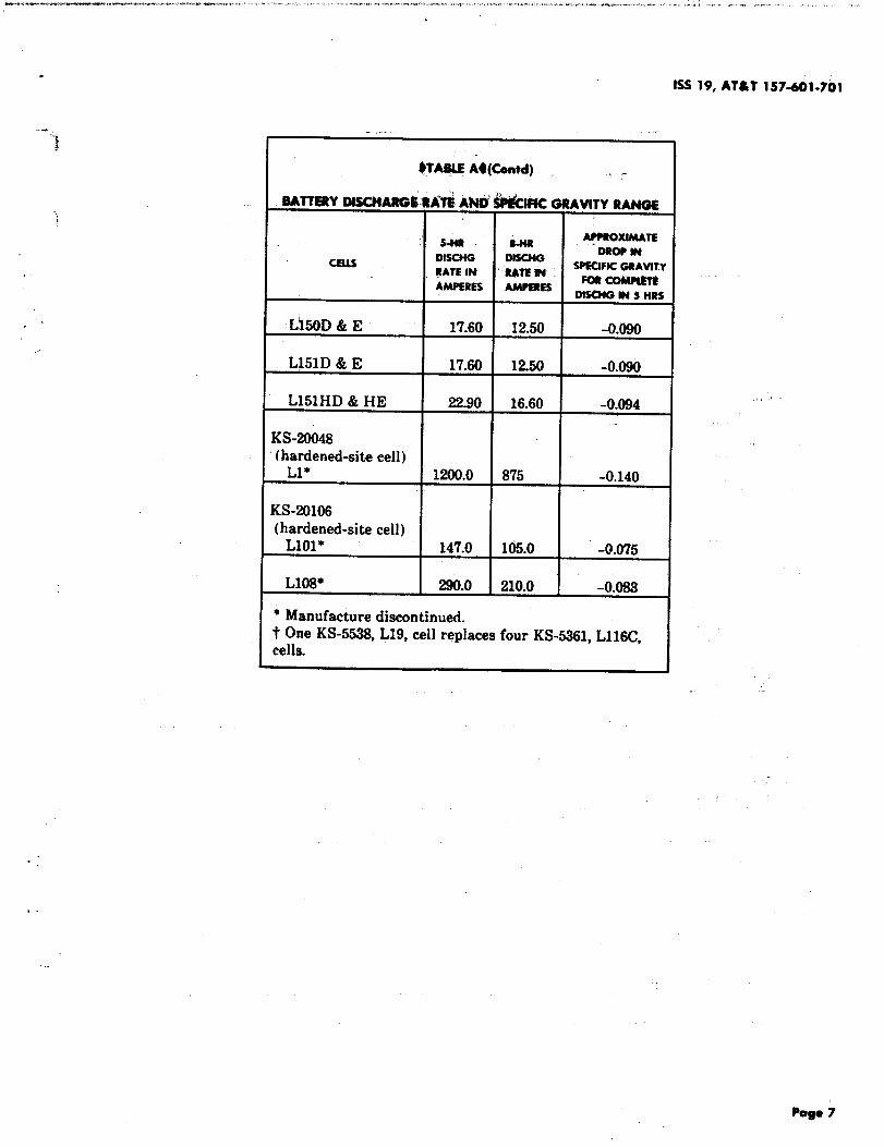
~TASIE A4(Contd) ‘,
BAITERY DISCllAR@k R#ti AIUU} tiPIC GRAVITY RANGE
S-W U-bsR A~XIMATE
CEus DSECHG OSECMG DRO?SH
RATE1?4 RATEl?4SPSCSFKGRAVIT1
AMPERES AMPSREE FORcoMmmDIS@G M S HRS
Lt50D & E 17.60 12.50 -0.090
L151D & E 17.60 12.50 -0.090
L151HD & HE 22.90 16.60 -0.094
K$20048(hardened-site cell)
L1* 1200.0 875 -0.140
KS-201O6(hardened-site cell)
L101* 147.0 106.0 -0.075
L108* 290.0 210.0 -0.083
* Manufacture discontinued.t One KS-5538, L19, cell replaces four KS-5361, L116C,cells.
‘.

~7&T 157-601-701
MA8LEM
GRiD MATERIAL AND NOMiti S#ECIFK GRAVITY
I@-QfMD WA= ~
TYPROP NOMIALSPfCIFIC
COOEOFallGRtoMATERml GRAVITY
lEAp4?mMONY MAO-CALCIUM 1.210 1.300
KS-.5361L115-L151E x x
L151H, 151HD, x xand 151HE
KS-5538 x x(KS-4361,with connectors)
KS-5553 x ,x
KS-55(U” x x
KS-1W4L31(J,1211, LK)2 ‘x x
L403, L405, L407.
x x
LAO!),L501, IA03*, x x
L505*, and 1308 x x
KS-15544L31OH,L?llH, “ x x
L40ZH, and L403H x x
KS-15754* x x
KS-15S86*L140D, L141D, L150D, x x
1.151Dand L151E x x
KS-15886*L151H and L151HE x x
KS-20048, 1,1* x x(hardened-site cell )
KS-X)1(J6,L]01* and L108* x x[hardonwl-site cell )
* Manufacture discontinued.

.
-.
..-.
1SS 19, AT&T 15~=60t-%01
. .
*TAel@C4
BATT~YAF4TlU?AtE0 LIH ON FCQATCHARGEAT77*F
Mm ANllClP~7~ INKMU~ LISTNuMaER YEARSwI’tqq#4bAlw
KS-5361, KS-15&36*,and 110-116 5’KS-5538 120-151D or 8
151E 6! 151HD and 151HE 2
KS-5538 All 5-8
KS-5553 All 14
KS-5562* All 14
KS-15544 All except List No. 1531OH, 311H, 4-403H
..
KS-15544 31OH, 311H, 402H, and 104oaH
KS-15754 All 7
KS-20048* All 14(hardened-site cell)
KS-201O6* All 15(hardened-site cell)
* Manufacture discontinued..,
{2) KS-20106, L1OI, and KS-20106, Note 1: Both KS-20048 and KS-201O6batter-LI08, (klk The KS-20Z06, LIOZ, cell
is a hardened KS-15544, L501, cell, while theKS-30X06, LI08, cell is a hardened KS-15544,.“ L508, cell. These cells use the special KS-5499,L5200, terminal connector. These cells arehardened by means of the KS-20054 accessories. .which include a fiberglass base, top retainer,side plates, and rubber cushions. The accesso-ries enclose the cell and pro;ide a means for-.mounting to the battery rack.
iesare rated Mfr ilk. and are to be replaced bythe KS-20472 $LINEAGE 2000 roundt cell.
Note 2: OThe KS-20472 LINEAGE 2000,,round cell is NOT a one-fer%ne replacemek forthe KS-20048 cell. Therefore, standard draw-ings should be checked to ascertain the numberof KS-20472 LINEAGE 2000 round cellsrequired.t
1.05 Cell Grid A#atert”aland Specific Graw”ty:Grid material and nominal specific gravity of
KS-coded lead-acid cells are shown inTAbleB. Uniess

I
,.
mm #. .
!, Mmlft-=mmw w ‘i t
*OF rYPE of slEcmalwE LsvE”,:
@..caNIAINaa
MAXIMUM MtNIMUM
KS-5261L116 to L151HE
KS-5528 ,,KS-6553 Plastic jar Bottom of - Top ofKS-15544 (transparent) high line low lineKS-15754 “KS-15886KS-201O6*(hardened-site cell)
KS-5553KS-5562
Nontransparent
KS-20048*”with float covers’
(hardened-site oelk) .
KS-5552Second dolor
Top of floatKS-5562 Nontransparent stem is flushKS-15544 without float ;:~;;:i;:m (or level)
covers with top of(u8M11Yred) float wide
Level with target aperture (usualIy
KS-5261 Plastic jartriangular) located approximately
LICUJto L114 (transparent) midway between separators andbottom of cover
* Manufacture disconked.
otherwise specified, all requirisments and recom- numbeting indicates @the date cdl(s) were shippedmended pmcedurem for lead-antimony cells also (date of manufacture) and the AT&T Technologiesapply to lead-calcium cells. individual cell(s) number(s) by manufacttirer.~
,,B. Mandadumrs’ MwWkatim and So&I Numbers (a) Manufacturere’Locatien l’&nt#fieation:
Whe manufacturing location identification is1.06 Ceil I&ntifieation Infwmation Location: outlined as follows 4
Manufactwers identifkd the facto~ where acell was manufactured by a letter or number stam~ (1) GOULD battery cells manufaot.uring loca-on one of the terminal posts, usually the $nega~vepost and/or a sticker on the batt@y jar cover. Both4the f~tory location and date of manufacture should ●
be mentioned on records and correspondence. serial
tion identificat~on codes follow
$D–designates the Depew factory (discon- ~tinued manufacturing location ).4
Pag# .%4)

-,.-.
J ● K—designates the Kankakee factory.
. OS—designates the Fort Smith, Arkansasfactory.4. ..
● T—designates the Trenton factory (discon-tinued manufacturing location 1.
. . .
(2) C&D* battery cells manufacturing locationidentification codes follow
- ..● A—designates the Attica factory.
,.
● C—designates the Conshohocken factory.,,
● J —designates the Conyers, Georgia factory.
● $1?’—designates the Santa’ Rosa, California(West Coast) factory (disccptinued manufac-turing location ).4
(3) EXIDEt batte~ cells manufacturing loca-
●
●
●
●
tion identification codes follow:
+1–designates the Philadelphia, Pennsylva-nia factory (discontinued manufacturing lo-cation ).
!?-designates the Richmond, Kentuckyfactory.4
$]—designates the Chicago, Illinois factory(discontinued manufacturing location L
2S–designates the San Francisco, Californiafactory (discontinued manufacturing loca-tion).
f4) *GLOBE* battery cells manufacturing lo-.cation is as follows
. . ● Milwaukee, Wisconsin factory.
(b) Weriaf Numbering: The serial numbering.,.,.. practice for the different manufacturers is
outlined as follows4
* Tradenmr~of (XD Battcriw
t Ir;ulwmrk of ESII Rrands [nmrpurntvd.
~ Trwlrmark of GLORE Ilattwy I)ivision, Jnhtwnn (’mtrol.
1SS 19, Al&l 1S7+01-703
(1) The serial number consists of nine digits.The first four digita indicate the year and
month of shipment (manufacturing date). Theremaining five digits indicate the individualAT&T ‘fkclinologies 5-digit cell identificationclamber.
(2) Serial number ,blocks of 20,o00 serial num-bers are ass~ned to each supplier as fol-
lows:
GOULD 00001 through 20000
C&I) 20001 through 40000
EXIIIE 40001 through 60000
9GLOBE 60001 through 80000.4
(3) The entire serial number may be on one lineor may be separated after the date portion.
The 5-digit manufacturers’ serial number blockportion is usually recycled every month.
Exampfe: 840140024
Where
~.
01 =
40024 =
I .07
(a)
Rules
1984 (Shipment Year)
January (Shipment Month I
Battery No. 40024shipped by EXIDE inJanuary ~984.
for Good Battery Maintenance:The followitig rules should be adhered to.
Maintain battery in a healthy state of chargewith as little excess charge as possible. Main-
tain correct float charge voltage values. (See TableE and Practice 157-801-301’.)
(b) Maintainelectrolyte level between maximumand minimum by the addition of approved
water. (See Table D.)
(c) Keep temperature of electrolyte within limits.
(d) Keep the battery clean.
(e) Replace cells where bulging, cracking, leaking,or other physical defects require replacement
Pq@ell
,
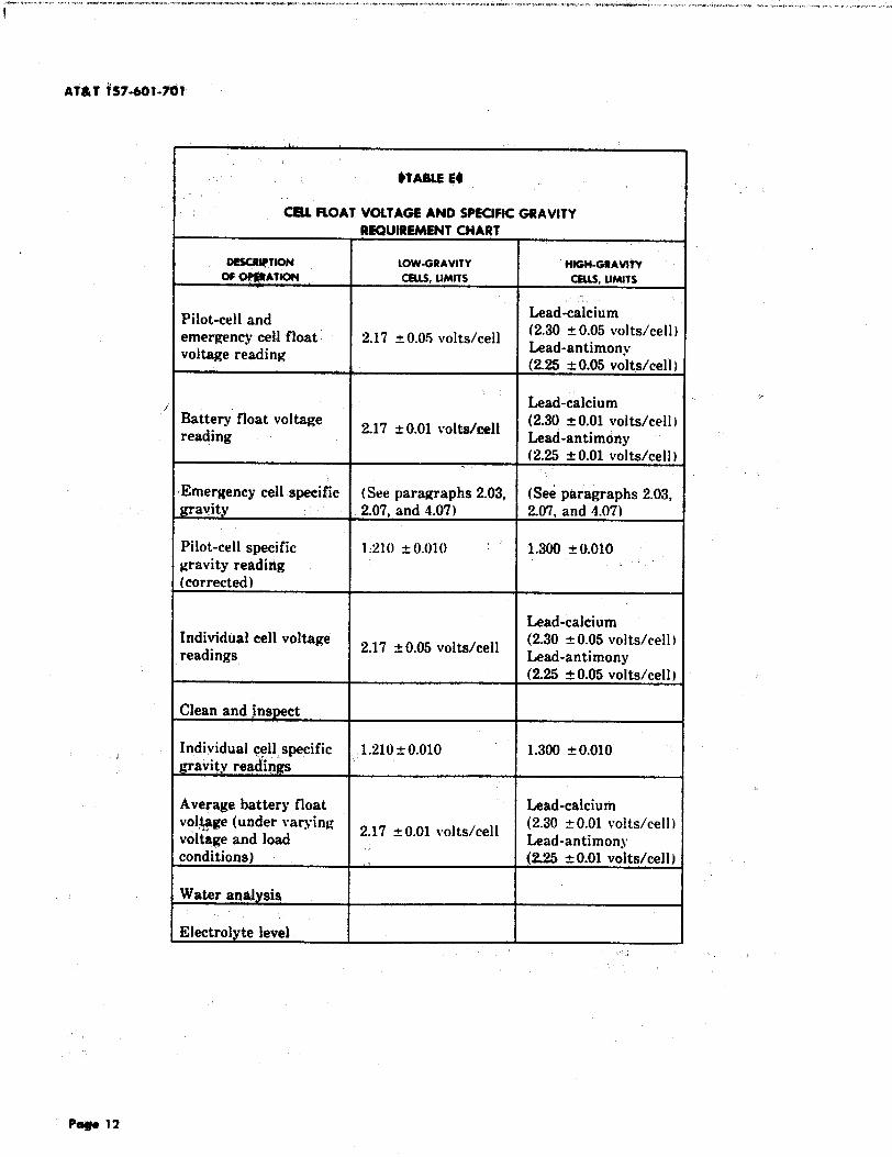
$TAMEE,
CEU PLOAT VOLTAGE AND SPECIPIC GRAVITY
REQUIREMENT CHART
oascawTloN LOW-GRAVITY Hlm-omvltiOF~ATION CELLS,LIMITS CELLS,LIMITS
Pilot-ceil and Lead-calcium
emergency cell float. 2.17 t 0.05 volts/cell (2.30 Y0.05 volts/cell)Lead-antimonyvoltage reading(2.25 k 0.05 volts/cell)
Lead-calciumBattery float voltage
2.17 k 0.01 VOb/M?ll(2.30 ~ 0.01 volts/cell)
reading Lead-antimony(2.25 ~0.01 volts/cell)
Emergency cell specific (See paragraphs 2.03, (see paragraphs 2.03,gravity 2.07, and 4.07) 2.07, and 4.07)
Pilot-cell specific 1:210 fo.olo ‘“ 1.300 t 0.010gravity readidg ,,
(corrected)
Lead-calciumIndividual cell voltage
2.17 t 0.05 volts/cell (2.30 *0.05 volts/cell )readings Lead-antimony
(2.25 &0.05 volts/cell )
Clean and inspect
Individual qell,specific 1.210t 0.010 1.300 t 0.010gravity readin~
Average battery float ‘ had-calciumvo~e (under varying
2.17 k 0.01 volts/cell (2.30 50.01 volts/cell )voltage and load Lead-antimonyconditions) (2.25 aO.01 volts/cell) ~
Water analysis
Electrolyte level
,“
P@#Is 12

and insure proper spacing between batteries. (See-.
3Practice 157-601-702.)
(f) Avoid using an open flame or creating sparks,including those from static electricity, near
batteries. Do not permit excessive gas formation%.~. or electrolyte leakage.,-
1.03 Anticipated Ceil Life: Table C shows theanticipated life in years of lead-acid cells. . .
maintained in accordance with this practice. Thesefigures are based on best available data but are givenfor planning purposes only. These life figures areaverage figures only..
C. Safety
1.09 Electrolyte Corrosion and Bodily Protec-tion: $Battery electrolyte is extremely corro-
sive to most material and human tissue. Therefore,exercise extreme care whenever handling batteryelectrolyte or working around batteries.t
1.10 tiDANGER: Wear protective equipmentsuch as rubber gloves, rubber aprons, full
face mask and splash-proof goggles when per-forming anv activi$y involving handiing of
.’ electrolyte, ceils contaim”ng ektrolyte, ormaintenance activities requiring exposure toshock or electrolyte contact from these ctdik AUlead-acid storage ceUs/batteries have enormousshort circuit capability. Extreme care should beexercised to avoid shorting out ceil and/or bat-tery terminals. Shorting a ceil or battery withan noninsuiated tool can vaporize or throw thetool. The use of INSULATED wrenches ismandatory.4 Personneipermitted access to bat-tery areas should be fully briefed on the hax-ards of handling lead-acid batteries.
(a) Corrosion: Most metal, vegetable, and ani-.“mal products are corroded by electrolyte, un-
less it is p~mptly neutralized. ,
(b) Electrolyte Burn Protection: DANGER:Wear protective equipment such as rub-
ber gloves, rubber aprons, and spfash-pwofgoggles when performing any activity thatinvolves handling of electrolyte, ceiku con-taining electrolyte, or mm”ntenanceactivitiesrequiring exposure to shock or electrolytecontact from these ceils. Bodily protection fromelectrolyte burns is provided by wearing full face
ISS 19, AT&T 15T-60~-7Ql
mask splash-proof goggl~ rubber gloves, andrubber apron wlwn workingwith lead-acid batter-ies. Rubber gloves protects the handa from ekctro-Iyte when working with lead-acid batteries.
(c) Eleetricai Shock and Burne Protection‘-’ 9DANGER: Whenever working around
battery stringe, any conducting artieiee onwrists, legs, ww”st, neck, or head shwid ai-ways be removed A ffashiigkt havi~ a pias-tic @r rubber housing should be ueed.~ Bodyprotection is provided by wearhg rubbet gloves,rubber apron, full facemask, splash-proof goggles,and the use of insulated tools. When it is neces-sary to work on a rack of batteries that cannot bereached from the floor, the use of a wooden ladderis advised. #Whenever it is necessary to workaround any string of batterie% ritqgs, wrist w’atch-es, metal bracelets, necklaces, belt buckles, etc.,should always be removed.4
D. PM Aid
1.11 First Aid for Electrolyte in Byes or onSkim= $Electrolyte in the eyes or on the skin
is a very serious matter, and immediate action isnecessary. Whenever working around batteries orhandling battery electrolyte, the following proce-dures should be observed.
Note: The KS-21527, Ll, eyewash kit and theKS-21527, L2, eyewash soIution have been MfrDisc. The replacements are the KS-21527, L3,eyewash kit and the KS-21527, L4, eyewashsolution.t
(a) Electrolyte Splashes and Burna: In case ofelectrolyte splashes, use of the OKS-21527,IA,
eyewash kit and KS-21527, L-4,eyewash solutiontare recommended. However, if the KS-21527, W3,teyewash kit is not available, use the following pro-cedure.
(1) Remove electrolyte splashed on the skin orin the eyes immediately by .fhashing the
affected area with Iargc amounts of plain tapwater.
(2) In case of electrolyte in the eye, pour waterinto the inner corner of the eye and ailow at
least 1 quart of water to run over the eye andunder the eyelid. A drinking fountain near athand may be utilized for this purpose.
Pogo 13

A’T&t 1s7.401-?01
(3) Place eye injurieswider the treatment ofaphysician, pref@ably at4 eye @Mi8)jSt, as
soon as possible. .,,,~
(h) Mounting Eyewash Kits: In areas wherethe OKS-21527,1$ eyewash kit and KS-21257,
L4, eyewash solution. me used, containers may bemounted on building columns, along wand, or atthe end of battery stands. $A KS-21527, L3, eye-wash kit must~ be within reach in approximately22 ~ti at any point in the battery area. Whe KS-21527,L3, eyewash kits. should be mountsid wherethey can be reached without opening doors, climb-ing ladders, or using stools.
Note 1: The $KS-21527, L3,4 eyewash kitmust be separated from other containers in thebattery area to minimize the seiectitm of thewrong contiiner in an emergency.
*lVote 2: Under federal regulation, e~pira-tion dates have appeared on the pint bottlessince February 1977.The pint and quart bottleswith expiration dates should be disposed of atthe time of expiration. The pint bottles with no
~expiration date may be kept indefinitely.4
(c) Areas Not Equipped with Flame-ArrestorVents: In battery areas containing engine-
start batteries $not equipped with flame-arrestorvents, the KS-21527, L3, eyewash kit alone is notconsidered satisfactory protection. In such areas,
~ consider replacing existing batteries with batter-ies equipped with expioeian-proo f vents..
Note: OFlame-arrestor vents may be orderedfrom the suppiier for celi(s) not originally
‘ equipped with them.t
E. Noutrcdkktg Agents
1.12 Agents for Neutralizing Lead-Acid Bat-tery Electrolyte: DANGER: Both elec-
trolyte kahage and neutraiixing solutions usedfor cieanup of electrolyte spilh may resuit. inconducting paths with attendant voitage haza-rds. OWhenever lead-acid battery electrolyte isspiiled, it should immediately be neutralized. TheCoilowingCan be used for electrolyte neutralizationpurposes:~
(a) Soda Solutions: Soda solutionsare”used for~enerai neutrdiization of electrolyte.
(1) Strong Sdda Soiutioru A strong soda so-iution, used primarily to neutralize spiliing
or drippin~ of electrolyte, is made by combiningeithe~ 2 pounds of baking soda (sodium bicar-
bonate), or 1 pound of washing $&da(sal soda)with 1 galion of water. One gaiioIs of strong sodasolution shoutd neutralize approximately 3/4pint of low-specific gravity $(1.210)4electrolyteor 1/2 pint of high-specific gravity $(1.300)4electrolyte.
(2) Weah Soda Solutiow A weak soda solu-tion for neutralizing traces of electrolyte
shouid be 1/8 the strength of the strong sodasoiution. A weak soda solution is made by com-bining either 2 pounds of baking soda (sodiumbicarbonate), or 1 pound of washing soda (salsoda) with 8 gallons of water.
Note: After using a soda solution, aiwayswipe the neutralized surface with a cioth damp-ened in clean water.
(b) Tetrasodium Pyrophosphate: The use oftetrasodium pyrophosphate (also known as
pyre) for general electrolyte nebtra!i~tion hasbeen discontinued for ecological reasons. However,the existing stock may be used up M notreordered. (Pyrophosphate may continue to beused, on an emergency basis, where immecliriteneutralization of iarge quantities of electrolyte ismandatory, such as might occur in undergroundinstallations. Use a concentration of 1/2 pound to1 gallon of water.) An acceptable nonpollutingneutralizing agent is available under the name of‘C-39Hard Surfaoe Cleaner.$ This generai purposecleaner is availabie from AT&T Technologies Ser-vice Center, Item No. 5127-1 COMCODE401753959.4
(c) 4micuiturd or Industrtai Lime: DAN-GER: Wear eye protection and rubber
gloves when using time on battery electrolytespills. Wash hands and face thoroughly afteruse. When it is necessary to neutralize very iargequantities of electrolyte, as in the event of a largespillage, agricultural or industrial iime may beused for this purpose as it is a more economicalneutralizer. A 25-pound bag of iime should neu-tralize the acid in a KS-15544 ceii.
(d) Ammonia Solution: A household ammoniasolution consisting of 1 part ammonia to 2
Pa- 14

f. .-”
parts water, should be used for neutralizing el,gc-trolyte on clothing. This solution will not causefabric spotting as readily as a soda solution. Usecaution when opening ammoniq ,@tt@i because ofpressure build up within the bottle. Ammonia liq-uid in vapor form is har+nful to the eyes and nose.Also, do not use ammonia near rotating chargingequipment.
Note: Do not use IGEPAL* C(3-6.30deter-gent for cleaning. A mild soap solution may beused ss described in paragraph 4.17. .
F. Explosion and Fire Prevention
1.13 Exp@ion and Fire Prevention: DAN-GER: AU lead-acid batteries generate
hydrogen gas, even under open circuit condi-tions. If not permitted to escape, this gas canbuild up to explosive concentrations in approxi-mately 1 week for pure lead or lead-calciumcells, and in as little as 2 days for lead-antimonyceils. NEVER seaf lead-acid cells under any cir-cumstances! When handliqg, storing, or ship-ping Jead-wid ceifs. the appropriate ventedorange shipp”ngpfug MUST be inserted into theopen vent hole to allow safe,venting of gases andto minim”ae acid spiffage. The mixture of hydro-gen and oxygen gases given off during charge, due toelectrolysis of the water, is explosive if in sufficientconcentration. A mixture of hydrogen and air is ex-plosive if the hydrogen concentration exceeds 944percent by volume. OThe following admonishments,precautions, and procedures should always hefollowed.t
*
(a) Static Electricity Sparks: DANGER:Avoid creating sparks, incfuding those
from static electricity, or the use of an openflame near batteries since the gas generatedby batteries is highfy explosive. Before per-forming each individual work operation,firmly touch a ground to discharge the staticelectricityy from your body. Electrolyte levelshould NEVER be allowed to drop below theend of the antiexplosion funnel. Take precau-tions against static sparks at all times and espe-cially while taking hydrometer or thermometerreadings or when installing new vents of any typewhile cells ard in service. These precautionsshould be observed when working on cells with or
Tradwnarliof GAF Corporation.
1SS 19, Al&l lS7-60t-701
without antiexplcwion features because of the pos-sibility of cover seal leak% post seal leaks, or con-tainers, which would bypass the antiexplosionfeature. OWhere static electricity is a problem,’thewearing of leather-soled shoes is recommended.Also, a slig~tly damp cloth, rather than a drycloth should be used to wipe plastic containers. Todischarge static electricity from body, touch w’grounded rack .or frame.t
(b] Charge and Discharge Explositwt Safety:Under normal float charge, discharge, and
recharge conditions, no explosion hazard existswith properly vented KS-15544 lead-calcium bat-teries. AU lead-antimony battert”es may con-tain an explosive atmosphere even undernormal ffoat charge conditions. Regardlessof the type of battery, it is prudent to alwaystake precautions agw”nst static sparks. Dur-ing boost charge (2.3 volts or greater), all thebatteries covered in this practice contain ex-ptosive atmospheres.4 If a spark (as from astatic discharge) enters the cell(s) under theseconditions, an expJosion may occur: Formaximum safety, *DO NOT handLe(avoid allcontact with) ceUs on boost charge and for 24hours after completion of boost charge.4
(c) Explosion Precautions: Special precau-tions should be used while taking hydrometer
or thermometer measurements or when installinga new vent or funnel while cells are in service. Bat-tery rooms and enclosures should be ventilated.Flames, arcs, sparks, etc., shoujd be avoided in thevicinity of the battery. At no time should electro-lyte level be allowed to drop below the minimum.The supervisor should ensure th~,t allantiexplosion admonishments and precautions ofthis practice and local instructions are followed.(See Practice 157-601-101.)
(d) Battery Connections: Do not loosen orremove battery connections while cells are
gassing or discharging unless it is absolutely nec-essary. If removal of connection is necessaW dur-ing this period, follow procedures specified insubparagraphs (a), (b), (c), and in paragraph 4.15.
(e) Battery Electrolyte Leakage or Spillage:Leakage or spillage of battery electrolyte
should not be allowed, especially where such leak-age or spillage might form: a low resistance arcpath to ground or between different potentials.
Poge 15

AT&7 i37-6owol
Avoid electfofyte leakhge or spillage which, inaddith to the ekctricai path hazard, will causeWrrosion.
(f)’ $Zlattery EiectroJyte M 4Electrolytelevel should JVOZ’be allowed to fall below
minimum since this allows the flame-arrestervents to be bypassed.
(g) E@rolyte Overffow: Electrolyte overflowfrom the vent funnel indictites clogged vents,
which constitutes an explosion hasard.
(h )“13attery Z’ermhud J%ds: The positive (+)and negative (-) ends of battery strings shall
not be adjacent. (See Practice 157-601-201.) Adja-cent cells in a string must not be allowed to touch
““{each other.
T.14 OZ’est Lsds: Whenever making voltagemeasurements, observe the following precau-
tions
. Use extreme caution when makhg voltagemeaimrements to prevent accidental ground-ing oi the leads during the test operations.
● Secure connections at the meter end.
● The test leads should never touch each otheror become grounded.~
● In no case should connections at the meterend be removed without first disconnectingthe test leads from the battery.
s The test Iead’ connections at the batteryshou Id be removed immediate] y after eachvoltage measurement is taken.
i. 15 DANGER: Awid creating sparks, includ-ing those from static electn”ciW, or the
use of anopen ffame near batteries since the gasis’ expfosive when sufficiently concentrated.Before Performing eaeh individual work opera-tion, firmly touch a grounded rack, or aninterceti connector near the groundcidend of thebattery, to discharge the static electricity fromthe body.
,;
1.}6 DANGER: Do not allow fZame-arrestorvents to become clogged as explosion due
to internal pressure may result. Such an explo-
siim “kaayshort circuit bther cdis and lead to afire.
G. BmtecY~in9 ,.’+
1.17 ~Boost Charge DANGER: During boostcharge and for approximatdy 24 hours
after end of boost charge, an explosive coticen-tration of hydrogen gas exists inside the celi.!l%erefore, to prevent an expfosion, cdfs mustNOT be handled dither during the boost chargeor during the 24-hour period folldwing a boostcharge. A boost charge is an overcharge of ariitrarylength, the overall time for each voltage being speci-fied. On float charged batteries, it may be given afteran emergency discharge and on the first evidence ofirregularity or undercharge.
Nota* Some batterypower plantsare not ca-
pable of boost charging and the cellsare float
charged continuously.
1.+8 Equaking (!ha?ge: DANGER: During.,:’ an equalizing charge and for approxi-matdy 24 hours after the end of an equalizingcharge, an expfe~fve concentration of hydrogengas exists inside ‘$heceU. Therefore, to preventan expfokion, cdis must NOT be hatuiiedeitherduring the equafixing charge or during the 24-hour pem”odfollowing an equafixing charge. Anequalizing charge is a charge that is continued to ameasured end that is, until current and voltage orspecific gravity have been stabilized for a specifiedtime. It is a form of overcharge given periodicallyunder some operating routines and in cases ofsulfation or other evidence of chronic undercharge.
1.19 Initiai Charge: An initial charge is the firstcharge given the battwies after receipt from
the manufacturer. It is quite important that thischarge be given as soon as possible after shipmentfrom the battery company to avoid excessive sulfateformation..
H. Fidd i?epaW
1.20 Repairable defects should be reported by wayof Engineering Complaints. Field repairs, in
many ca~s, are such that they can only be performedby the battery manufacturer. Th@se repair proce-dures must have prior approval of the $AT&T Tech-nologies Supplies, Marketing, and Engineerintz(SM&E) or~anization. Consequently, request for

1SS 19, Al&i 1S7401-701
approved field reRair should be made directly to the
“>battery supplier with a copy to AT&T SM&E-for ‘In-formation Only.’4
L Index of leod-Acid Battery Requirements ond’Prece-
dures,-
‘] 1.21 OInformation in both Part 2 and Part 4 hasbeen arranged under the headings shown in
Table F.
J. Recommended wtntenattce Intervals
1.22 Recommended maintenance procedures andintervals for the batteries covered by this
practice are found in Table G. 4.
2. REQUIREMENTS
A. Battery Records
2.01 Battery Records and Readings (Proc4.01): M3attery record forms should be filed
and maintained for the life of the battery. Recordswhich provide a history of the battery may provehelpful in clearing problems with the battery.t
i (a) Maintain complete battery records for each.,string of cells. Engineering complaints on bat-
tery performance cannot be accurately analyzedand satisfactorily settled unless they are accompa-nied by records which provide a thorough historyof the cells in question.
(b) Any particular set of measurements and read-ings for a battery, including all measurements
and readings within a string, should be taken bythe same person using the same instruments. Alltest meters shall be calibrated by using the samevoltage standard.
,!.’
B. Battery Measurements
2.o2 Float Voltage Measurements and Read-ings (Proc 4. 02): See OTable E for the indi-
vidual float voltage requirements.t Suggested. intervals between float voltage measurements and
readings are given in Table G. Refer to Practice 157-601-301 for special float voltage conditions. ,
--.’(a) OThesevoltage requirements provide an oper-
ating range which is consistent with maxi-mum battery life and reliability. However, cells
outside these requirements will not necessarilyfail prematurely or catastrophically. Whether or‘not celis operating outside the required voltagerange will affect system reliabilitydepends upon
the cause of abnormal voltage conditions as ex-plained in paragraph 4.02.
(b) Voltage values used in operating routines arenot corrected for cell temperature. Record
electrolyte temperature at time of voltage read-ings so cell behavior can be accurately analyzed.t
(c) Calibrate power panel voltmeter in accordancewith Practice 100-510-701. Set voltmeter hav-
ing external adjuster as accurately as possible ator near float charge voltage. The head of the ad-justing screw may be covered with tape to avoid“accidental and unauthorized changes; OInk theadjustment date on the tape. On voltmeters havingno external adjuster, mark or tag the instrumentor note in records4 the correction to be applied tothe measurements and readings and the date ofcalibration. This should be done on an annual ba-sis.-,
2.03 Specific Gravity, Reference Tempera-ture, and Floating Bail Charge Indicators
(Proc4.03): The specific gravity of low-gravity andhigh-gravity cells at electrolyte temperature of 77°Fshall be as follow=
(a) Low-Grauity Ceihx For low-gravity cells–1.210, with a tolerance range between 01.200
and 1.2204
(b) High-Gravity CeUs: For high-gravitycells—1.300, with a “tolerance range between
$1.290 and 1.310.4
Take specific gravity readings before, rather thanafter water additions or charging. After addingwater or charging, lead-antimony cells will regaintheir full charge specific gravity in about 2 weekswhile lead-calcium cells take about 10 weeks. SeeTable E for specific gravity readings of standard, pi-lot, and emergency cells. $Suggested intervals be-tween specific gravity readings of standard, pilot,and emergency cells are given in Table G.
C. load-Sulfate Crystals
2.04 Identification of hmd-fhdfate (kystais(plastic Cases) (Proc 4.04): Under normal
Page 17””

9TABLEP4
iNDEX OF MAD-ACID BATTERY REQIJIR~TS AND PROCEDURE$
PART2 PAET 4
EuaJEcl HEADING REaUmMmr ~EPAuAGawn P~
W- NuMaEa
A; Battery Records~tti~ Ib&jrds ~d Readings ~ 201 4.01
B. Battery MeasurementsFloat Voltage Readings 202 4.02S@cific (l!%vity, Reference Temperature, and 2.03 4.03Floating Bali Chaqje Indicaton
C. Lead-Sulfate CrystalsIdentification of Lead-Sulfate Crystals (Plastic 2.04Cases)
4.04
D. Battery Charging.
Emergency Ceil Specific Gravity and Charging 2.07 4.07Boost Charge Rate 206 4.06
E. cell R4?WTSSiSCd] Reversal 2.09 4.09
F. Battery ElectrolyteTemperature of Electrolyte 210 4.10Freezing of Electrolyte 2.11 4.11Water Addition and Level of Electrolyte 2.12 4.12Electrolyte LeveI Indicator Floats 2.13 4.13
G. Battery Discharge Capacity Tests and ReplacementCriteria
Discharge (lapacity Tests and Replacement. 2.14 4.14Criteria
,-
H. Battery Connections and General MaintenanceBattery Connections and Use of NO-OX-ID A* 2.15 4.15Containers and Covers 2.16 4.16Use of Tape to Temporarily Seal Plastic Jar 2.17 - 4.17CracksSeals 218 ‘ 4.18Spacing Between Containers 2.19 4.19Flame-Arrestor Features 220 4.20Spray Caps and Vent Holes 2.21 4.21Battery Racks, Stands, Cabinets, and 2.22 4.22Miscellaneous Equipment
* Trademark of Sanchem Incorporated.
Pag* 18 ,.,

1SS19, AT&t lS7~l-701
. . .
,“’
....
I
. .
i- ..
. . ,-.
TA@lEe
,RscoMmMol!o MAwttENANcEWmdwus -
TASK INTEUVAL PARAGs#n
Calibrate voltmeter 12M 2.02
Check battery float voltage w 2.02(or each visit to unattended sites)
Check emergency cell float voltage 2.02(or each visit to unattended sites)
Check individual cell float voltage 4M 2.02
Check pilot cell float voltage 2W 2.02(lead-antimony) (or each visit tounattended sites)
.,
Check emergen cy cell specific gravity 2.03
Check pilot cell-specific gravity 4M 2.03(lead antimony)
Check pilot cell temperature 4M 2.10
Check individual cell specific gravity I 8M 2.03
Inspect for lead-sulfate crystals 4M 2.04
Check electrolyte level (lead antimony) 6M 2.12
Check electrolyte level (lead calcium) 6M 2.12
Perform water analysis w/o kit 12M 2.12
Inspect level indicator floats 12M 2.13(hard rubber case)
Check connections for corrosion 4M 215
Ins pect containers for cracks and leaks 4M 2.16
Check battery jar for cracks and 4M 2.16electrolyte leakage
Poge 19

.
,7AM @fContd)
RRC~ MAJNTQIM w pm@vqs
TASK l~VAL PARAGRA?H
Inspect ba&tery jars for cracks and 2M 2.16electrolyte leakage (battery eve+ 8 yearsold and in battery strings greater than48 volts)
Clean and inspec t battery seals 4M 218
Check spacing between containers 4M 219
(oreach time maintenance is performed)
Clean and inspect 4hfflame-arrestor features
Clean and inspect spray caps 4M 221
Clean and inspect battery 4M 222racks and stands
k%fp 20

“%4 float conditions, all cells should be free of lead-1 sulfate crystals. The absence of lead-sulfate crystals
throughout the life of a battery plant indicates thatthe cells are float charging properly arid maintaininga full state of charge. Cells shall be inspected for-,-.
i lead-sulfate crystals to insure that cells are main-taining their charge.
2.OS The disappearance of lead-sulfate crystals or. . .gray coloration occurs from top to bottom dur-
ing recharge. To insure total absence of lead-sulfatecrystals or gray coloration, where possible, inspec-. .tion for lead-sulfate crystals should be concentrated..-.at the bottom of the positive plate. The flashlight is.,held close to the jar wall at an angle of approximately45 degrees. The lead-sulfate crystals will appear assparkling diamond-like reflecting particles or as graycoloration. Record presence or absence of lead-sulfate crystals on battery maintenance records inplace of cell-voltage measurements and readings.
2.06 If lead-sulfate crystals appear on all cells in abattery string, the following should be
checked as possible causes for the abnormal condi-tion. $The presence of lead-sulfate crystals is not nor-mally an indication that the battery or cell is
‘h incapable of providing adequate capacit~ therefore,..,”corrective action for crystalline cells is not an urgentitem. A crysblIine ce[l will suffer an immediate 10SSof 2 to 5 percent of its rated capacity. Any furtherdecay in capacity will depend upon the precise causefor the crystalline condition. The best way to assessthe ability of a crystalline cell to deliver capacity isto make a specific gravity reading. If the specificgravity is in the normal range of 1.200to 1.220for lowgravity cells and 1.290 to 1.310for high gravity cell%then the deration in cell capacity will be minimal.Concern for the ability of a crystalline cell to deliverreasonable capacity should begin when the specificgravity is less than the normal minimum.t
(a) Rectifier VoU~e: ‘The appearance of lead-sulfate crystals may indicate a low battery
float voltage. Check to see if the individual cellfloat voltage is correct according to Table E. Makeappropriate rectifier adjustments if necessary.(See paragraphs 2.02 and 4.02.)
(b) Plant Discharge: A battery discharge re-sulting from a power failure, testing, or other
reasons may produce Iead-sulfah crystals on thecell(s). This is normal with ali lead-acid cells sincelead-sulfate is the material produced when a lead-
1SS19, AT&T 157-@~-701
acid cell is discharged. If the cause of the lead-sulfate crystals is a recent. di~har~e, the crystalswill disappear when the cells have been fully re-charged on float (usually within 2 weeks). It ismandatory to log all ac input power failure alarmsin battery maintenance records.
D. 8attery Charging
2.07 Emergency CeU Specific Gravity andChar~”ng (Proc 4.07): Emergency cell spe-
cific gravity shall fall no lower than 1.130.Watch thefirst group of emergency cells careful~. A series ofemergency discharges may discharge the first groupof emergency cells much more than the main batteryor the second group of emergency cells, making cellreversal a possibility.
2.08 Boost Charge Rate (Proc 4.08):#DANGER: During boost charge and for
approximately 24 hours after the eiui of boostcharge, an expionive concentration of hydrogengaa exists inside the ceil. Therefore, to preventan explosion, cells must NOT be handled eitherduring the boost charge or during the 24-hourperiod ~oUowing a boost charge.~ A boost chargeshould be given, where possible, to the main batteryand for the emergency cells if they have had any ap-preciable discharge or if it is known that there has’been one emergency discharge or a series of short dis-charges which (a) were the equivalent of 1/2 hour ormore during the heavy-load period of the daw or (b)caused the corrected specific gravity to drop 15 per-cent or more of the cell’s gravity range for full dis-charge. See Table A for dpedic gravity ranges oflead-acid cells. Be sure lew specific gravity is dueto discharge and not to recent addition of wa-ter. Pilot-cell specific gravity measurements andreadings should be taken to determine the extent ofemergency discharge when the length of the emer-gency discharge is unknown. Boost charge acceler-ates return to a full charge condition. In plants whereboost charge facilities or capabilities are not avail-able, full charge wiil eventually return to a dis-charged battery on normal float charge. OThe fullcharge will returnt at a slower rate than with boostcharging. t(see Fig. 1 and”Practice 157-601-101.)4
E. Cdl Roversah
2.09 CeU Revareai (Proc 4.09): If one or morecells in series become fully discharged while
the remainder of the cells are still discharging, there
Pagq 21

C14~lNG TlbM ,- 04?S c8s300w
r,.
~“Fig. 1 -T#l “~~ ~~ Fdr o Fully Dischar# Leo&Cakium Battery
:-
will be a ceil reversal, that is, change of polarity onthe discharged cells. O1frepeatedseveral time% thereis adverse effects on the plates of the reversed cell.t
F. Betruy 4ktrolyto
2.10 Temperatw-e pf Efeq$rolyte (Proe 4. 10kThe best ce!l temperature, considering both
life and capacity, is from 65 to SO°F. Temperatureslower than 65*F are objectionable only because oflowered battery capacity. High temperatures are ob-jectionable because of increased positive plate corro-sion and the resulting decrease in battery life. Ifoperated at electrolyte temperature above 90°F forover 2 months per year, battery life expectancy mustbe reduced by 20 percent. For lead-calcium cells, thelife at 90”F is only half that at 77°F; and at 100”F,the life is 1/3 that at 77*F. The life of lead-antimonycells at 90°.F is 3/5 that at 77°F and at 100°F, the lifeis 1/3 that at 77eF. Therefore, operation at elevatedtemperatures is not advisable and, except on initialcharge, llO°F should not be exceeded. (See Practice157-601-201.) For effect of temperature on specificgravity, [see subparagraph (b) of paragraph 4.03];and for effect on capacity and voltage, see Practice157-601-101.
2.11 Freexing of EJ&trolyte (Proc 4;1 1): Theelectrolyte in any cell shall be maintained
above the freezing temperature respective to its spe-cific gravity as shown in Table H. Freezing will causedamage not immediately apparent. (See Practice 157-601-101.)
2.12 Water Addition and Level of Electrolyte(Proc 4.12): Warni~: OverfiUing the
cefl ean lead to plugn”ng of the gae ~nts. At alltimes afterinitialcharge, the level of electrolyte inany cell shall be maintained as indicated in Table D.The drop rate of electrolyte level will vary considera-bly depending, upon cell design and upon operatingand atmospheric conditions. The addition of watermust, therefore, be .at intervals as required at a spe-cific location.
2.13 Electrolyte Lewd Indicator Floatq (Proc4.29): Electrolyte level of rubber jar cells is
indicated,, by electrolyte level float indicators. Theindicator consists of a float and a float guide (Fig. 2).The electrolyte indicator ,for the EXIDE KS-5562cells are flltted with a transparent cover over the ex-posed stem part of the float. The cover is etched withlines to indicate the high and low level of the electro-
Puge 22

---4.
) IWABLE H4
FREEZIHG TEMHtATUREOF IEAD-ACIO MTIEl@ Electrolyte
F@ ~AwttEE?EaFicGaAvlTY‘v-AT25.O”C(77%) ‘“’“c ‘F
1.030 -1.11° +30°
. .1.060 -3.33” +26°
1.090 -6.6° ! +20°
1.120 -8.8° I +16°
1.150 I -13.3° I +8°
1.180 -19.9° -4°
1.210 -30.6° -23°
1.240 -46.7” -52°
I 1.270 I -65,0” 1 -85°
1.283 -728° -99”
lyte. The electrolyte lgwel indicator for the GOULDcells without a cover has the float stim col,orhd toiqdic~te the electrolyte level. The minimum level of
$ electrolyte is indicated when the top of the float stemis flush (or level) with the top of the float guide.Floats shall be free to move with electrolyte levelchartges. To check float indicators equipped withoutcover, depress the float indicator and observe thatthe float does not stick when released.
G. Battery D=harge Capacity Tests and Replacement
Gtteria
..
2.14 Discharge Capacity Tests and Replace-ment Cm”teria(Proc 4.14): The rated ca-
pacity or ampere-hour capacity of all ceils is based onthe 8-hour discharge rate except for KS-20048
1ss 19, AmT 1S7-601$W
(hardened site) cells where it is based on the 5-hourdischarge rate. In practice, the 5-hour discharge rateis used to determine the reserve capacity of alI cellsbecause a 5-hour discharge test can be completedduring a normal 8-hour work day. Table A gives the5- and 8-hour discharge rates in amperes of lead-acidcell~presently used in telecommunication offices andother power plants. Table I is used for the KS-5562L04, L05, L06, and LO?,tank cells.
H. Battety Cenneatiens ond Generol Moint*nance
2.1s Battery Conn@ons and Use of NO-OX-ID A. {Proc 4d6): U!aution:
Overtighting of the in@wcell connectors couldstrip the bolt aitd/or nut threads resulting inloose connections.4 Qmnections shall be tight andfree from dirt and corrosion. OConnectitms should bechecked according to the suggested intervals in TabIeG. or per local practices. (See Practice 157-601-702.)Do not loosen or change connections without firstreferring to subparagraph O(d)4 of paragraph 1.13and paragraph 4.15.
2.16 Contr#”nera and Covers (Proc 4.16):DANGER: Acid leakage can cauae short
chwits, corrosion of terminals and intercellconnectors, and is a potential fire haxard. Cori-tainera and covers shall be free from cracks and leak-age or spillage of eleqtrdyte.
2.17 Use of Tape to Temporarily Seal PfasticJar Cracks (Proc4.Z7): haky jars shall be
replacqt. Cracks in plastic jars that are leaking shallbe temporarily sealed $with. acid-resistant ta~~when possibIe, while awaiting ceil replacement.
.
2.18 Sede (Proc 4. 28A Post seals and any sealsbetween covers and containers shall be intact
and free from electrolyte or residue.
zli Spacing Between Containers (Proc 4. 19):DANGER: Celh or batteries, ee~ialfy
those with ftexible connectors, sho@d bechecked for spacing every time mattiknancework is performed. Proper spacing of celfspre-vent thepossibilit y of fire which can occur if theceii.sare in contact with each other. Where con-nector terminale and terminal det@8 extendbeyond the battery cover, use extreme care toavoid shorte when moving the ceUe. Spacingbe-tween containers shall be as specified in Practice 157-601-201. The KS-5562 tank cells may bulge with age
Page 23

“., ,
,.
,.
:,“, .’,
“4??ETU@O
!1ELEcmYTELEVEL LINES
TRAMSPARENTFLOAT COVER
II
tFLOAT !STEH
.,,
,,
FLOAT
ti ‘
tJ{
d
LEAO STRIP(EX1OE]
● ●
EXIOE.,
FLOAT(SPllf?
FLOAT
—,,-*W ‘“
\
Y
TYPE)/
kf,
SOULD
COLOREDGREEN
CQLORE&
%. ?4-Rubber fMtory Jar t%ct+to LOWIIndiitw -m
“ .{’
FLOATSTEH
8A’plate growth occurs. Total bulge (both .sid& com-bined) shall not e~eed 3/4 jn~h-
2.20 Fiame-Arreetor Features (Proc 4.20):@4NGER: Do not all~w gas vents to bec-
ome clogged as spraying or o~rffow due tointernafpreeaure may reeult. Flame-arrestor fea-tures shall be dry, clean, and undamaged. Vents ofthe screw type shall be screwed down to a snug fitwith no leakage through the seal. Vents which arepermanently cemented in place shall be fi~mly seatedand tialed at the base. $Inspect and gaugeantie~losion features by eye.t
2.31 Sp~ Caps a~ Vent Holee tProc 4;21):Spray caps shall be clean and in plaoe. (See
Practice 157-601-201.)The vept holes shrdl be openand free of residue. @Inspect and gauge spray capsand vent holes by eye.t
2.22 Battety Racks, Stande, Cabinets, andMisoeffaneoua Equipment (P~qe 4.22):
Battery racks, stands, cabinets, and miscellaneousequipment shall be clean and free from corrosion.Ra6ks, standsi and cabinets shall, be level and prop-erly ~rounded. (See references in paragraph 4.22.)Mnspect and gauge corrosion and grounding by e~e.~
Not= Peeling paint or corrosion may indi-cate a leaking cell.
. ..

““j$TAME 14
EXPKTED RESERVE~ I(S-5562* TANKCHLS AT 600 AMPERES DISCHARGE
1 I
‘J Csus HOURSM
(MINures)
I Lo4 I 6 I 360 !
L05 8.2 492
11 660
L07 13 780
* Manufacture discontinued. I
3. APPARATUS
3.01 List o~ Tools and Test Equipment: DAN-GER: The uee of insulated wrenchw does
not change the requirements for protecting ex-poeed adjacent metal with fiberboard, canvas,
> or rubber sheeting as may $e appropriate. The.-foilowing tools and test equipment are used in thispractice. Equivalents may be substituted for thoselisted.
Note The wrench sizes are included for in-formation only and do not have to be includedwith the ordering information.
Tools DESCRIPTION
* WIAF Test Cord
R106O Putty Knife.-
R2969 Typewriter Brush.
— KS-6496, L1401, Syringe TypeCell Filler
Orange Stick
R-481o l/2-Inch Wrench, Box,DET 1 Insulated
Tools
R-481ODET 2
R-481OD~ 3
R~i310DET 4
R-481Ob~ 5
R-481oDET 6
R-481O1DET 7
R-481O1DET 8
R-481ODET 9
R-481ODET 10
R-4501
1SS19, AT&T’ t37060WOl
DESCRIPTION
9/16-Inch Wrench, Box,Insulated
5/8-Inch Wrench, Box,Insulated
3/4-Inch Wrench, Box,Insulated
13/16-Inch Wrench, Box,Insulated
7/8-Inch Wrench, Box,Insulated
15/16-Inch Wrench, Box,Insulated
l-inch Wrench, Box, Insulated
1-1/16 Inch Wrench, BOAInsulated
1-1/8 Inch Wrench, BcnqInsulated.:
Test (kWd$, WESTON* No.254761-901and No. 168028
3-Inch C Screwdriver
Battery Filler, E. Edelman &Cempany No. 74C
Smaii Paint Brush (obtain lo-cally)
Soldering (%pper, PyramidPoinL 1 or 2 pounds
. .
Flaehligh~ regular or angular,having plastic or rubber hous-ing
Goggles, Ceverall, Clear Lenses
* Trademark of NTMOh’ 1nstru ments, n Divison d Smgamo,
Inc.
Psl#02s
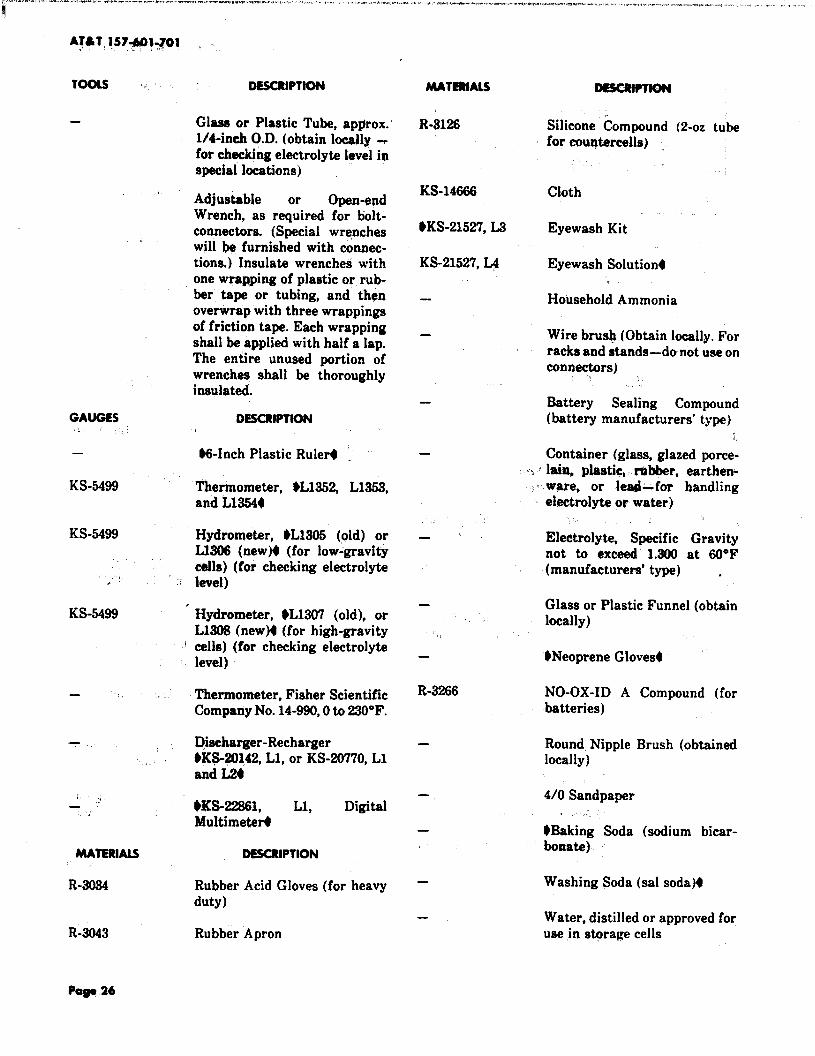
GAUGES
—
KS-5499
KS-5499
,,:’
KS-5499
y.,
MATERIALS
R-3034
R-3043
.
DESCRIPTION
Glass or Plastic Tube, approx.l/4-inch O.D. (obtain lcKwJly_for checking electrolyte level inspecial locations)
Adjustable or Open-endWrench, as required for bolt-connectors. (Special wrencheswill be furnished with connec-tions.) Insulate wrenches withone wrapping of plastic or rub-ber tape or tubing, and’ thenovefirap with three wrappingsof friction tape. Each wrappingshall be applied with half a lap.The entire unused portion ofwrenches shall be thoroughlyinsulated.
DESCRIPTION
$6-Inch Plastic Ru1er4 .
Thermometer, OL135Z L1353,and L13W
Hydrometer, $L1305 (old) orL1306 (new)O (for low-gravitycells) (for checking electrolytelevel)
Hydrometer, $L1307 (old), orL130S (new~ (for high-gravitycells) (for checking electrolytelevel)
Thermometer, Fisher ScientificCompany No. 14-990,0 to 230”F.
Discharger-RechargerM@-20142, Ll, or KS-20770, L1and L24
9KS-22S6L Ll, DigitalMuItimeter4
DESCRIPTION
Rubber Acid Gloves (for heavyduty)
Rubber Apron
MATERUS DESCWPTION
R-$126 Silicone Compoundfor countercells)
KS-14666 Cloth
OKS-21527,L3 Eyewash Kit
KS-21527, ~ Eyewash SolutionO
‘;,
R-3266
(2-02 tube
.,
Household Ammonia
Wire brush (Obtain locally. Forracks and stands-do not use onconnectors) :,
&ttery Sealing Compound(batterymanufacturers’t~pe)
“..
Container (glass,glazed porce-
~ lain, plastic, r@ber, earthen.----ware, or lead-for handling
electrolyte or water),:
Electrolyte, Specific Gravitynot to exceed 1.300 at 60°F(manufacturers’ type) .
Glass or Plastic Funnel (obtainlocally)
.Neoprene Gloves.
NO-OX-ID A Compound (forbatteries)
Round Nipple Brush (obtainedlocally)
4/0 Sandpaper.,,,
$Baking Soda (sodium bicar-bonate)
Washing Soda (sal soda)t
Water, distilled or approved foruse in stqrage cells
kg, 26

MATERIALS DESCRIPTION-.,.
]_
“i—
c-39
—
—
—
4. PROCEDURES
Wiper, Paper, SCOTT* No. 58,59, or 059R4
Wax, Battery Jar Biack, No.5300 (from EXIDE) (1 quart)
Hard Surface Cleaner–(Avail-able from 9AT&TTechnologies. Service Center,Item No. 5127-1 COMCODE401753959)
$Approved Mild Soap SolutionsJOYt Dtsh Washing Liquid(Mfr–Proctbr and Gamble~LUX$ Dish Washing Liquid(Mfr–bwer, Brothers~ DOVE*Dish Washing Liquid (Mfr-Lever Brothers); IVORYLIQUIDt Dish Washing Liquid(Mfr–l%mcter and Gamble);PALMOLIVES Dish WashingLiquid (Mfr–Colgate-Palmolive Company)
Acid-Resistant Tape (2-inchwide )
Electrical Plastic or RubberTape (3/4-inch wide)
Friction Tape (3/4-inch wide).t
A. Battery Ruords
4.01 Battery Records and Readings (Reqt2.01): $Battery record forms should be filed
and maintained for the life of the battery. Recordswhich provide a history of the battery may provehelpful in clearing problems with the battery.t
(a) OForms E-2(M3(Fig. 3), E-3591 (Fig. 4), E-3592and E-3593 (Fig. 5),4 are typical forms sug
IS 19, ATM W7-#M#Ol
gested for recording various measurements andreadings.
(b) Record the date and time of all measurementsand readings or date and time of starting a
series of readings such as individual-cell volts orspecific gravities.
(c) Record the temperature whenever specificgravity readings and voltage measurements
are taken. It is not necessary to take the tempera-ture of each individual cell. The temperature ofone cell on each tier will be sufficient.
Note: Unused space on forms maybe used torecord irregularities such as excessive amountof water required.
B. Bottwy Measurements
4.02 Float Voltage Measurements and Read-ings (Reqt 2.02): +DANiM?R: Accidental
grounding of battery connected test leads, whilemaking individual cell voltage readings or averagebattery float voltage readings, can result in seriousinterruption to service. In order to avoid this possib-ility, extreme caution should be observed when tak-ing these readings. Connections at the meter endshould be secure and free of any possibility of touch-ing or becoming grounded. In no case should connec-tions at the metar end be removed without firstdisconnecting the test leads from the battery. Thetest lead connections at the battery shouid be re-moved immediately after each voltage measurementand reading is taken. Always observe polarity andproper scale (if applicable) when measuring cell orbattery voltage to avoid possible damage to the.meter. Use the 3-volt scale of an approved digitalvoltmeter for measuring voltages of both low-gravityand high-gravity cells. Voltage measurements andreadings should always be taken with the voltmeterleads connected directly to the battery terminals andnot to the interceli connectors.t
(a) If the voltage requirement is not me%the fol-lowing should be checked as possible causes of
the abnormal condition
(1) Rectifier Vahge: Low- or high~voltagecells may be due to incorrect average bat-
tery float charge voltage. Check to see if theaverage battery float charge voltage conformsto the requirements in Table E, i.e., 2.17 aO.01

.
PRsmOEs U.s. h. ,Fm E-sow SMUT NO
STORAGE BATTERY RE~HlOIV:DLIALCELL RE@Illu2
cm m
REAOI03S srATE
lMSM SY OPFKX
AmoUEosT BATS !9
CELLSEmms ClwoE “wa alAAoE
SsLLWORE SnARw AFTER CMROE
m.~TfR ;~: &~ED :$s n,vUUwE~ :&” ‘“‘“ *“ woSOmSR gg’ ‘“ -“ H MV~TER
lEW.
IWRFSXEO5P OR
REAoIwi. ,,
AsnolIeCORRESTEO ELEC. CORRECTED
F 10 F F TO F &“ 70 FREAOIW
F TO F
SAT , w.
rxm[
Tm g
t I
.-
!
d,.. . “
%b f
SAT.
IPILOT CELL 90. II
SAT.m. I PILOT CELL m. I
SATFm. m. I PILO? CELL NO.
Pig. 3–Porm E-2003 Stosoge BsstteryRecord
Page 2a

‘-l
.,
1ss 19, AT&7
..$ .-. ,. WOW,+..,. ,., ,,
1s741-701
-s=-i ~x-ss,.=, IICSLLS RRQUIRI_
I
1
PRINTSDIll U.S.A.FM E-9SS1(11-WI - no.
STORAW BATTERY RECORDS
WATERADDITIONS, SWALIZIW - -1 ~
OPf ICS , CITY AM STATE
RSAOX- FM To
- :-~:E--=SAT. M.
PILOT CELL SP. 0s.OATE Tms -RK7E0
*ILOT REM. AP?.vals AMPS. ~; y “ ~p -L BY BY
1 t 1 I 1
I 1 1 I
I 1 I 1 1 1\
I I I I 1 1 1
I I I 1 II
1 I I II i
I I Ii I
I I1 1 I
I I \
1 I 1 I 1 1
I4
I I I 1I
I I 11 I 1
I 1 1I I I
1 ! 1
[
I 1 I I1
I 1 I II 1 1 I \
I 1 I 1
II
11
I I I
REMARXS
F~. 4—Form E-3591 Stosogo Battery Record
PO@ 39

AT4T 1S7+1-701
MIMTSB IN U.S.A.
$Wl E-3593111-4S) sttEsT,ND.
,.
STORAGS BATTEllY RE~DS - INDIVIDUAL CELL VOLTAGES
OFFICE, CITY C STATE READXWS FRM ‘To
REAO. BY I MAO. BY 1APF. BY AFF. BY
BAT..,‘, I BAT.
- ,*m OATE
_,,11= TIM
CELLVoL’rs VOLTS Vars VOLTS
No ND VOLTS VOLTS VOLTS VOLTS VOLTS VOLTS
..
I tI
I II
11 I 1 II I
r 1I . .
II i
I[
i iI
I II I
i i P i1 I i i
I t )I I 1
I 1I I I
t I Ii I
II
II I I
1
I 1 I
1
REMARKS
Fig. S—Form E-3593 Storage ~ttery Ruord-lndividvol Cell Voltoges

...= volts per cell for low-gravity cells, and 2.25
.1 -0.01 volts per ceil for high-gf%vity, iead-antimony cells, and 230 +0.01 volts per cell forhigh-gravity, lead-ca~~ium cells, respectively.Make appropriate rectlfler adjustments if nec-
,. essary..,’
(2) CeU Temper@ure Variation: Impropercell voltage conditions may result from. .
temperature variations between cells in thesame string. This is most likely to occur inmultitier arrangements where, because of natu-ral air convection, the temperature of the toptier cells may be significantly higher than thelower tier cells. The warmer cells (top tier)would have lower float voltages than the coolercells (bottom tier). If the difference between thewarmest and coolest cell in any string is morethan 5°F, appropriate ventilation should be pro-vided to cxwrsct the situation.
(3) Cell Munufaeturers: Cells made by thedifferent manufacturers, even though they
have the same capacity rating, have differentfloat charge characteristics. Check to be surethat all cells are from the same manufacturer.
(4) Ceff %P@$: Lead-caluium and lead-antimony cells have different float charac-
teristics. A lead-calcium cell mixed in with astring of lead-antimony cells will have a floatvoltage much higher than the lead-antimonycells. Conversely, a lead-antimony cell mixed inwith a string of lead-calcium cells will have afloat vokage much lower than the lead-calciumcells. Check cell identifkation labels to be surethat all cells are of the same lead-alloy (KS-number).
(b) If the above conditions are not mdt or cannotjbe identified as the cause of devjation from the
float charge voltage requirements, take the follow-ing steps
(1) C& Vtdtage High In general, cells qer-ating slightly above the required voltage
limit do not indicate a trouble condition and noaction need be taken. However, cells float
.. . “ charging at voltages significantly higher thanthe upper voltage limit must be examinedclose]y since such a condition indicates that pos-sibly one or more of the plates are no longer inthe cell circuit. Any cells floating at a voltage
M 19, At&i 137-601-7ot
highei ‘than the upper voltage requirements,i.e., greater than 2.22 volts for low-~vity cell%mater than 2.30 volts for high-gravity, iead-antimony celi~ and greater than 2.35 volts forhigh-gravity, lead-calcium cells, should be in-spected C1OSSIYfor dvidence of loss of one ormore plates from the cell circuit. Replace anycells which show loss of plates from the cell cir-cuit.If visualinspectiondoes not revealany-
thing,a dischargetestshould be run on the cell
in question. If the capacity is low (see para-graph 4.14), the cell should be replaced. If bothvisual inspection and the capacity test do notindicate a trouble condition, no action needs tobe taken. However, special attention should begiven to the regular voltage measurements andreadings. Replace the cell if the float voltage ofthe cell in question continues to increase.
(2) Cell Voltage low: For cells that werefloat charging within the required range at
the previous quarterly voltage reading, float‘Wtages less than $2074 voks for low-gravitycells and less than 2.14 volts for high-gravityc411sindicate a severe abnormality —pomibly ashort circuit—and should be replaeed. ~w-gravity cells between $2074 and 2.09 voltw high-gravity, lead-antimony cells between 2.14 and2.17 voltq and high-gravity, lead-calcium cellsbetween 2.14 and 2.22 volts also indicate an ab-normal condition. These cells should be boostcharged as soon as possible. If boost chargingpermanently corrects the abnormally low-voltage condition, no other action needs to betaken.
(c) If the cells voltage is still abnormail~low afterboost charge or if the cells return ‘to abnor-
mally low float vohge within a year”after boostcharge, tlie cells should be replaced. If the cells re-turn to abnormally low-voltage conditions at anytime exceeding 1 year after boost charge, boostcharge again and follow the procedures given inthis paragraph.
(d) Other low-voltage conditions, i.e., below therequired minimum float voltage but greater
than 2.09 volts for low-gravity cell% greater than2.17 volts for high-gravity, lead-antimony cellsand greater than 2.22 volts for high-gravity, lead-calcium cells, are more difficult to analyze and dis-position of these ceils can only be decided afterfurther tests.
Fag831

A;&T 15.7401.701
(e) If the voltage is still low qt the next quarterlyrezu%% the cell should be given a boost
charge, and if this cor~ts the low-voltage condi-tion, no further action nee& to be taken. If boostcharging doea not cmrect the low-voltage condi-tion, the low-voltage cells should @ given a dis-charge capacity test 6 months after boostcharging. Replace cells only if discharge testsshow low capacity.
(f) If a siagle-cell charger is not readily availableand the power plant is capable of hn equaliz-
ing or boost+ charge, operate the float/charge keyMa charge position4 when the battery voltagedrops below the minim~m requirements [see sub-paragraph (c) of paragraph 4.08]. A single-cellcharger may still be required for individual cellsif the Oequalizing or boosto charge does not bringthe cells within minimum voltage requirements.
4.03 Specific Gravity, Reference Temperatureand Floating BaU Charge Indicators
(lleqt 2.03): DANGER: When tahipg specificgravity readings, the open end of the hydrome-ter sdwUbe covered with ~a paper toweti whilemoving it from ceU to ceff to avoid sptihing orthrowing the electrolyte. ‘Tocheck these require-ments, proceed as follows.
(a) ~Hydrometer “~pee: Use the KS-5499,L1305 (old) or L1306 (new) syringe-type hy-
drometer for low-gravity cells ~d the KS-5499,L1307(old) or L1308 (new) syringe-type hydrome-ter for high-gravity cells. (See Table E for specificgravity requirements.)4
(b) ~+ference Tempe+ure and Effect ofTenq+wtq=e on Specific Gravity: Warn-
ing: Never insert a ther~pmeter into the elec-trolyte withdraud tube” or use..a mercury-fiUed thermometer 40 take temperature mea-surements and readings. Use the KS-5499,Llw thermometer for cells of 100-ampere hoursor less and the KS-5499, L1353, thermo~eter forcells over 100-ampere hours. Specific gravity read-ings and electrolyte @mperature readings must betaken within a few minutes of each other. Thethermometers now being supplied have scales forcorrecting to the proper reference temperature of77°F. If a thermometer with correction scale is notavailable, calculate the correct specific gravity byadding 1point (0.001)for each 3°F that the electro-lyte temperature is above 77°F or by subtracting
1 point ,fO.~1) for e~h 3°F that the electrolyte~mpera~ure is below 77’F.
JVote: Thermometers in which the indicatingliquid has separated shall not ‘be used $andshould bi dhwarded.t
(c) Specific Gravity Readings of CeUs Withi%ctrdyte Withdrawal lkbes: $Specific
gravity measurement and readings of lead-acidcells with electrolyte withdrawal tubes are takenby first exhausting the hydrometer bulb with theflexible tube inserted in the battery water fillerflannel. Then, with the bulb still held depressed,insert the flexible tube into the battery with-drawal tube located in the corner of the batterycover. Releasing the bulb will draw battery elec-trolyte into the hydrometer, which must then becarefully removed to facilitate retilng the specificgravity number on the hydrometer float at thesurface of the elect!rcdyte.The hydrometer must beexhausted in the water filler funnel (not the smallwithdrawal tube ) of the cell from which the elec-trolyte was removed. This procedure should pre-vent battery electrolyte from splattering from thehydrometer flexible tube during handling..
(d) Specific Gravity Readings of Cells With-out @ectroly@e Withdrauxd %bes:
Warning: ~Miydrometere4 used in lead-antimony, iead-cafcium, and KS-204P2 LIN-J!iAGE2000 round ceU batteriee shaff not beinterchanged since they wiU contaminate theelectrolyte. Specificgravity measurements andreading of cells without electrolyte withdrawaltubes are taken by inserting the hydrometerthrough the opening which is used for the additionof water. However, readings must not be consid-ered accurate unless 10 weeks have elapsed sincecharging or adding water for lead-calcium cells or2 weeks for Lead-antimony cells. Slowly fill andempty the hydrometer several times before re-cording readinga in order to wet the float, mix theelectrolyte, and equalize the temperature of thehydrometer and electrolyte. Exercise care to en-sure that the top of the hydrometer does not touchthe stop in the hydrometer buIb since this wouldcause an erroneous reading. Exercise care to avoiddripping or spraying electrolyte from the hydrom-eter tube.
(e) Assembling Hydrometer Syringe: DAN-GER: In order to avoid possibfe serious
cuts from brohen gks, extreme care should

1SS19, AT&T; lS7-601h
be used in WmbUng the hydrometer sy---r,) ringe. If die hydrometer be pvvioueiy been
used, it hay p@asibly contafn some #ectro-lyte clinging to theuxdl of the glass barrel orrubber hose. Goggles shoufd be used in asaem-
:,+
bfy operations to protect the eyes. (See Steps(1) through (4).]
(1) Remove any mold seam finsfrom those sur-faces of the rubber parts which in assembly
fit against the glass barrel.
. .(2) Before assembling any rubber parts to the
. glass barrel, wrap several thicknesses ofheavy cloth around the barrel to protect thehands.
(3) Always wet the rubber parts and that por-tion of the glass ~barrel wher~ the fitting is
to take place prior ,to assembly o~rations.
(4) After performing Steps (l), (2), and (3), fitthe rub~r partsto the g$tis barrel.
(f) Floating BaU Chrge Indicators: Chargeindicators are furnished on some smaller cells.
The indicators are wax balls of selectw$ specificgravity. The three colored ball indicators (blue-green, white, and red) provide the following spe-cific gravity indications
(1) The blue-green ball drops’when the specificgravity falls to 1.195 AO.002.This ball drops
first on discharge.
‘(2) The red ball drops when the specific gravitydecreases by an amount representing be-
tween 62- and 69-percent discharge frbm thefull charge value.
1,. (3) The white ball drops when the s~cific grav-ity is approximately half-way between the
gravity requirements of the blue-green and red.-indicators.
Note: The indicators in Steps (l), (2), and (3)assume a well mixed electrolyte, at the highlevel, with a temperature of ??”F.
..(g) S~ific Gnzvity Out of Range: Specific
gravity measurements below the requiredrange are rare and indicates that the cell is self-discharging and consequently losing capacity.
Boost charge a ail when specific gravity is belowthe required minimum. If boost charging perma-nently corrects the condition, no action needs to betaken. If the specific gravity is still low after boostcharging, or if the condition reappears within ayear of boost charging, replace the ceil.
C. Lead-Sulfate Crystcds
4.04 I&ntifi&tion of ~-fhdftie Cryatafs
(Plastic Cases) (Reqt 2.04k There shouldbe no lead-sulfdte crystals or gray coloration presenton the positive plates or straps when examined witha flashlight. l%rmally, only the positive strap will beaccessible for examination. In some arrangementsthe edges of the positive plates will also be visible(Fig. 6). The visible positive elements shall be blackor dark brown and totally free of any diamond-likelead-sulfate crystals or gray coloration. The disap-pearance of lead-sulfate crystals normally occurs inthree distinct phases
Phase 1: Black and crystalline
Phase !2 Gray and lightly crystalline
Phase 3 Black or dark brown and crystal free.
4.OS “Thedisappearance of lead-sulfate crystals orgray color@i~,~urs from ,top to bottom du~-
ing recharge. To in- @@l abaeme of lead-sulfatecrystals or gray coloration, where possible, inspec-tion for lead-sulfate crystals should be concentratedat the bottom of the positive plate. The flashlight isheld close to the jar wall at an angle of approxiniately45 degrees. The lead-sulfate crystals will appear assparkling diamond-like reflecting particles o? as graycoloration. Record presence or absence of lead-sulfate crystals on battery maintenance records inplace of cell-voltage readings.
4.06 If lead-sulfate crystals ap~r on one or p fewcells in a string, the following actions should
be ~ken.
lVot~ A battexy discharge resulting frompower failure, testing, or other reasons mayproduce lead-acid crystals on the cells. This isnormal with all lead-acid cells sinqe lead-sulfate is the material produced when a lead-acidacidwill
cell is discharged. if the cause of the lead-crystals is.a recent discharge, the crystalsdisappear when the cells have been fully
?ogo 33

Ar~T 1S7+01:701. .,; .
/Rw$t,P
FORPLA
PLASTIC JAVISOITOM 1
2-J””
II .
I
k \bOSllJVE PLATE
1 \NEGATIVE PLATE SEPARATOR
NOTE:CHCClt FOR LtAO-SULFAlC~S7ALS ONAREAS MARKED W17U XXX’S.
Pig. &–Typkal Rost@nguksr - hvvkt~ P- loca-
tion of LeOdSulfat. +ofals on Poshivo Elomonts
recharged on float (usually within 2 weeks). Itis mandatory to log aftac input power fail-ure aiar~ in battery maintenancehecords.
(a) Plant Discharge: Check to see if a plant dis-charge has occurfkd.
(br CeUShor@k ,Measuie the cell voltage. If the,~i crystalline eeif(s) indicates 2.09 volts or less
and the cell visible positive elements are black andheavily crystalline (Phase 1), the cell is shortedand should be reported in an engineering com-plqjnt.
(c) “’CeU Tempemture Variatimx, Measuretemperatures of cells in each tier of the
~‘ string(s) to determine the extremes of tempera-ture differences. Temperature differences of 5°F
or more between cells in a string can result in afloa%~problemwith the Warmer -11s which wouldresult ia the appearanm of @rysta14;If tetnpera-ture differences inexcessof4$*Parefound,appro-
priateventilationshould be providedtacorrect thecondition. I~
y.,
(d) Single-CeU is Crystalline: If the problem isnot attributed to a shorted cell [see subpara-
graph (b)], or to a “CSUtemperature uariation[see subparagraph (c)], the cell(b),should be boostcharged at 02.5 to 2.554 volts with a “single-cellcharger. The boost charge should be continued forat least 24 hours after thd lead-sulfate crystalshave disappeared. ‘Upc)ncompletion of the boostcharge, the cell should be allowed to float chargein the string.
(1) *DANGER:, Duri~ ~ost charge andfot’ kpproximatdy 2?4 hours after end
of boost charge, an”’kpiotn”veconbentmtionof hydrogen gas exists. Therefore, to pre-vent an explodon?, c@s mubt NOT be ban-died “eithdh during’ the “boost charge orduring the 24-hou,F peripd following aboost charge.t If Iead-su}fate crystals do notreappear on’float charge, no action needs to betaken.
,..
(2) If lead-sulfate crystals do reappear, the cellshould be reported as an engineering com-
plaint. Copies of the battery record should alsoaccompany the complaint.
(e) Multiple CeUsAre Crystalline: If the prob-lem is not attributed to shorted ceilk [see
subparagraph (b)], or to a ceU, temperatureuariation ‘[see subparagraph (c)l, it is recom-mended that the battery string be boost chargedat 2.5 to 2.55volts per cell. The boost charge shouldbe continued for at least 24 hours after the lead-sulfate crystals have disappeared from all cells.Upon completion of the boost charge, the cellsshould be allowed to float charge in the string.
(1) If lead-sulfate crystals do not reappear onfloat charge, no action needs to be taken.
(2) If lead-sulfate crystals do reappear, thecells should be reported as amengineering
complaint. Copies of the battery record shouldalso accompany the complaint.
Pago 34,,

D. Boitory Gorging“=.
I4.o7 J3rnerge~ CCU Specific Gravity and
Charging (Reqt 2.07): If corrected specificgravity is low (see paragraphs 2.03 and 2.07), boostcharge as described in paragraph 4.08.-.
c,4.08 Boost Charge Rate (Reqt 2.08~ Use the
following proq@ures when boost charging thebattery.
(a) *DANGER: During boost charge W@ for. . . approxima@y 24 houre after end of
boost charge, an exphe@e concentration ofhydrogen gae exiate. Therefore, topreuent anexplosion, ceUe must NOT be handled eitherduring the boost charge or during the 24-hour period f@owing a boost charge.4 Boostcharges after power failures are given where pos-sible to the entire string for durations dependingupon charging voltage as shown in Table J. Specialboost charges, including those made necessary bylow voltage or low specific gravity on one or a fewcells, may be given to the string or to certain $e-Iected cells only. See Practice 169-621-301. J9m”ngbattery to fuU charge or nearly 80 beforestart of boost charge. Cells are close to fullcharge when the current through them at chargevoltage is too low to be read on plant ammeters orwhen the difference between charger output andload as read wi the plant ammeters has beennearly the same value for 10 minutes.
(b) Where it is necessary to booet charge only afew cells, it may be more convenient to use a
single-cell charger $at 250 to 255 volts.t
(cl The fcdlowing action should be taken for boostcharge in 50- or 52-volt, 120- or 400-ampere
plants only
(1) Plant in Officee Where the MaximumAUowabfe Voltage la ~ Volta: In these
plants, an equalizing or boost charge should notbe applied by mesns of the TST-NOR-CHG key.In the event one or more cells fail to meet the
voltage requirements, the cell or cells should begiven a boost charge on an individual cell basis.
(2) Plant in Officee Where 52-Volt Opera-t$on Is Permitted: In these plants, oper-
ate the TST-NOR-CHG key to CHG. Aftercharging is completed, operate the TST-NOR-
[ss 19, AT*T as7.691-701
*TAM N
BATTERY WOST CnARu8 Tlw
‘.rtma INmuusSAnmv
Vom Pm cm .,lsaN8QosTcr4ARas
MAXIMUM
2.ti ‘ 2.7 i.12.49 3.3 2.4.2.48 3.6 2.72.47 4.2 3.3246 4.8 3.624!5 5.7 4.2
2?44 6.6 5.1243 7.5 . 5.7242 8.7 6.6241 10.2 7.82.40 11.7 9.0
239 13.5 10.52.38 15.6 12.0237 18.0 14.1236 20.7 16.5235 24.0 19.2
27.6 222233 32.1 25.8232* 37.2 29.7231* 43.2 34.5230* - 49.2 39.6
229* 57.5’ 46.52.28* 67.2 54.02.27* 77.4 61.22.26* 90.0 7232.25* 104.0 84.0
2.24* ~ 1220 97.0223* 141.0 113.02.22* 1620 1320221* 187.0 1520220” 216.0 176.0
‘The lower voltage values (voltages leas than!.33), are for use with low-gravity da only.‘he minimum volts per cell shall be 233 forI@h-gravity cells.

CHG key to NOR for 52-volt operation or to TSTfor SO-voltoperation. ~
(3) Powfr.$’’aihre &tw&pe: NO ~tion i8re@nd. If “the~~~~~] is in the circuit,
theeountercefl wN}automatically switch out ofthecircuit rmd,w~, res~tition of power,,auto-matically switch into circuit when the batteryrettehes float ~alta@. In 52~volt plants oniy, theTST-NOR-CHG key may M operated to CHG torestore battdry vottage more quickly afterpower failure. <
(d) To give a boost tiha~e as shown in Table J,frost Taise the vokageto the charge yalue pro-
vided for in the “patiictilw ‘piant. This nay takeonly a few minutes Yor .a charged battery whichhas been float charged accurately or it may takean appreciable amount of time if the battery ispartially discharged. After charge voltage isreached and the battery is thought to be fullycharged or nearly so .[see subparagraph (a)],charge for a time within the maximum and mini-mum shown for that voltage in Table J.
ExamPie: At 2.20volts “per cell, the chargetime shall be from 176 to 216 hours. With e}ec-trol.yte temperatures above 95°F, the minimumlength of boost chqrge is preferable while attemperatures below @M”F,the maximum is pref-erable. If charge voltage is greater than 2.30volts per cell, watch the pilot-ceil temperatureand interrupt the’charge before ‘11O”Fis exceed-ed, and complete later or at reduced voltage.
(e) On a boost charge of emergency cells by load,the charge may h“ terminated when:
... ..
(1) The length of time of charge is within themaximum and minimum shown in Table J,
and the cell voltage (average of 15-minute inter-val readings) is w’ithin limits.
(2) The ampere-hours (average current timeselapsed time) equals 100 percent of the 8-
hour rated capacity of the cells.
(3) 9 Warm”ng: Temperatures exeeedi~’110°F may damage lead-acid ceils.4 In
either case, watch the temperature of the bat-tery electrolyte and interrupt the charge, if nec-essary, to prevent temperatures from exceeding
11O”F. Complete charge later or at a reducedrate.
E. Wl,Revmcd
4.09 .Ceii Reversal (Reqt 2.09): Cell ‘&versa]-may occur when a battery plant is allowed to
discharge in excess of its rated capacity. Since sta-titmary lead-acid dells are generally designed withexcessive negative plate capacity, the positive platesin a cell can undergo reversal without the cell show-ing an actual revixwd of cell polarity.”The possibilityof .revorsing,a cell(s) Should besuspected whenever abattery plant is discharged below an average of 1.75volts per ceil. If any cell reads 1.0 volt or less towardthe end of discharge, the Wdithre plates of that cellhave probably been reversed, and the cell may pres-emt a problem on recharge. A reversed cell typicallyhas a high resistance because the acid specific grav-ity’is very low, and the voltage will beextremely highif the cell is recharged at normal rates. “For severelyreversed celis, it is not unusual to obtain voltages inexam of 4 volts when the. cell is being recharged inseries with nortreversed cells at 2.17 volts per cell av-erage. At such high voltages, cell temperature in-creases rapidly and irreparable ‘damage can becaused. Consequently, reversed cells must be re-charged -slowly and with caution in order to avoidhigh temperatures.
(a) Identification of a Reuemed Cell(s): Wf acell is suspectedto be revcn%ed,perform the
following steps to identify the reversed cell(s).t,.
(1) If cell reversal is suspected, measure undrecord the battery voltage and plant load
prior to restoring the rectifiers. Also record thedates and times for the start of the battery dis-charge and when the rectifiers were restored.
(2) Immediately after restoring the rectifiers,measure~ndividual cell voltages.
(3) -Thereafter, measure individual cell volt-ages hourly for a period of 5 hours.
(4) If at any time a cell(s) reads more than 2.5volts, that cell(s) has been reversed and cor-
rective action is required.
(b) Corrective Action—Battery Plant Zs a,! Single String and Cannot Be Di8a8soci-ated From the Power Plant: For reversed

1SS 19, At~T 1S7-601-701
. ..
1
.’ .,1<z,.
. .
,,
. .
;
~-
,.
cell(s) in a single-string battery which cannot bedisastiithed from the battwy power plant, per-form the following corrective action.
(1) Control the rectifier(s) output voltage sothat the highest cell does not exceed 3.0
volts. ,.
(2) The vol@e 6f the highest cell(s) shouldbegin to decrease as this cell(s) begins to
accept a chkkge. The time required for this tooccur can vary from several minutes to weeks,depending upon the degree of reversal. As thevoltage of the high cell(s) graduaIIy deimeases,gradually increase the rectifier(s) output volt-age (not exceeding 2.17 volts per cell ) while stillmaintaining the high-voltage ceil(s) below 3.0volts.
(3) When all cells are reasonably uniform involtage; i.e., aIl in the range of 2@?to 2.27
volts, and the recharge current is less than 5amperes, the string shall be given an equaliz-ing charge. The equalizing charge shall consistof a standard measured end initial charge at 2.5volts per cell as described in Practice 157-601-201. For this charge, stability has been reachedif corrected specific gravity baaed on hydrome-ter readings at top of cell is 1.180 or higher fora low-gravity cell, or 1.270or higher for “ahigh-gravity cell. After this charge, the cell capacitymay be even higher than before the reversal,but there may also be internal damage such ascracked plates and loosened active material.Cells that have been reversed should be watchedmore care~uiiy during the remainder of theirservice life. The above equalizing charge willrequire bringing in an auxiliary string of cellsso thatthe string w be charged can be disassoci-ated from the wo~kbg plant. If this is not possi-ble, the equalizing charge can be performed onan individual cell basis using a single cell charg-er.
(c) Corrective Action—Battery Plant HasParaiiei Stm”nge: For reversed cell(s) in a
parallel string battery, perform the following cor-rective action.
(1) If all battery strings have reversed cells,follow the procedures outlined in subpara-
(2) If alt battery strings do not have rdveraed
cells, disconnect the string(s Jwith reversedcells from the power plant and followthe proce-dures outlinedin subparagraph (a).
(d) Contingencies for Revers&i Gli(ak If therevereed celi(s) fails to respand to the above
procedures, any of the following may be attempt-ed.
F.
(1I ,Shunting Around Reversed Ceil(s):Shunt around the high:voitage cell(s) which
will allow maximum recharge current to flowthrough the nonreversed cells. This maybe doneby paralleling the high-voltage ceil with a suit-ably sized resistor or with a single cell dis-charge unit in order to maintain the high-voltage cell(s) between 2.0 and 3.0 volts. Oncethe nonreversed cells have been recharged, theshunt can be removed from the reversed ceil(s)and the reversed cell(s) can then be chargedwith a single cell charger at 2.5 volts at thehighest available current. The above shuntingprocedures become impractical if more thantwo cells have reversed in a string.
(2) Disconnecting Reversed Ceil(s) FromString: Disconnect the reversed cell(s)
from the string and charge these individually orin parallel at 2.5 volts. Meanwhile, charge thenonreversed cells in series at 2.5 volts per cell.
(3) After StepS (1) and (2) have been success-fully applied, an equalizing charge must be
applied as described in subparagraph (b), Step(3).
(4) Contact the regional OAT&TBell Laborato-ries field representative and/or the area
AT&T Technobgies4 Quality Semite Engineerif further assistance is required.
4.10 Temperature of Electrolyte (Reqt 2. 10):Use the KS-5499, L1352, thermometer for celis
of 100-ampere hours or less and the KS-5499, L1353,thermometer for cells over 100-ampere hours.
Note: Thermometers in which the indicatingliquid have separated shall not be used $and
graph (a). should be discarded.+

ta) Warning: Never insert tke thePmQ@eterWo the electrolyte m“thdruwai tubew or
w a mermwy-fiiled thermemtier tb taketemperature reudinge. To check the tempera-ture of electrolyte, insert the thermometer intothe ce~ t.hr~~h the -me opening that is used forthe addition Of water. Compl@ely submerge thebulb of the thermometer in the electrolyte for atleast 2 minutes before the reading is taken. Ifthere is insufficient clearance to insert the ther-mometer without rem,oving the cell from the rackor cabinet, an approximation of the cell”tempera-ture may be obtained by laying the thermometeron top of the cell for .at least 10 minutes beforereading. However, pilot cells shall always be acces-sible for the insertian of the thermometer into theelectrolyte.
[b) Prevent excessive terq~ratures by adequateventilation, blinds on windg,ws, heat shields
between cells and radiawrs, etc. Where possible,electrolyte temperature of ceils within the samestring should be within 5°F of each other. The toprow of 3.tier racks is particularly apt to havehigher temperatures than the bottom row. Wherenecessary, use fans and other forms of ventilationto lower the temperature of the top row as nearlyas possible to that of the bottom row. A pilot celltemperature reading must be taken and recordedfrom one cell on each tier of a 3-tier string.
4.11 Freezing of Electrolyte (Reqt 2. Z1):When there is danger of electrolyte freezing,
imtnediate steps should be taken to provide specialenclosures. insulation, or heaters as necessary.
4.12 Water Addition and Level of Electrolyte(Reqt 2. 12): *DANGER: Wear protective
equipment suck ae rubber gloves, rubberaprons, and splaeh-proo f goggles when per-forming any activity involving handling ofelectrolyte, ceils containing electrolyte, ormaintenance activities requiring exposure toshock, or electrolyte contact from these cells.The use of insulated wrenches is mandatory. Tomdnt&in the battery electrolyte ‘level, proceed asfoliows.t
(a) IJse only distilled water, deionized water, orother water approved for storage battery use
, to bring electrolyte up to tk required level. Maxi-mum aJlowable impurities are given in Table K.OElectrolyte checking interval is dependent upon
local conditions.. When the actual electrolyte tem-t perature is below 50°F, d~,not rai~tbeielectrolyte
level appreciably above the minimum level. Thishelps to prevent an overflow on charge and elec-trolyte meepaxe difficulties.,,.
@TA~ M,
tiXIMllkt AUOWABl,ElthPIJRITiESW wTTERY WA~
~“ OF ‘hJmtoRMwlTElfIMPURITY (OYWelaW)
FERCSNT
rotalSolids 500 0.0500
?ixed Solids 350 0.0350
lrgdc and M ,’ 0.0050lo~atile Matter
.,
~hloride 25 0,0025
ron 4 0.0004
titrates and 15 L.9015$itrites
kmmonia 5 0.0005
danganese 0.07 o.m7
(b) OWarning: Interchanm.ng hydrometers,fbnneis, and other battery tools between
battery types wiU result in contamination ofthe electrolyte. Hydrometers, funnels, and otherbattery tools used in lead-antimony’ lead-calcium,and KS-20472 LINEAGE 2000 round cell batteriesshall not be interchanged. .4cid or electrolyte shallnot be added to any cell as a substitute for ade-quate charging. Do not contaminate the electro-lyte of lead-antimony cel~ with electrolyte fromlead-calcium cells and vice versa. EXIDE lead-calcium funnels have a green or blue distinguish-ing band to indicate that they are of lead-calciumcomposition. Funnels of other manufacturers maynot be so marked. Do not use these funnels inter-changeably. Plastic funnels will not contaminate
Page 38

--rI-#, but must @ rimied with clean water before using1 to fill different tq~ of’cells. Under no circum-
stances shiill elet%olyte be dis~sed tif in”such amanner that may result in environmental pollu-tion or damage to equipment. The electrolyte
‘4! should be neutralized where” the possibility of
damage might occur.1
(c) Approval of Local Water: To obtain ap-, proval for local water, have it analyzed by ei-
ther a local laboratory or one of the batterycompanies.
(1) Each sample should be’ 1“quart of local,.>water in a clean polyethylene or gIass con-
tainer with a nonmetallic closure.
IVote: Current U.S. Post Office regulationsconcerning the shipment of liquid filled glasscontainers should he observed. The label oneach sample should give the fotlowing data
● .Name of company
● Town and state
● Date sample was taken
● Source of water supply such as ~rvoirs fedby streams, or from wells, a local ‘well, cis-tern, etc.
(2) Before a particular water source can be ac-cqpted, one sample should be taken during
the wet season and one during the dry season.If either sample is not satisfactory, the watershould not be used for batteries. It is necessaryto have the water reanalymkl annually, Any for-merty unsatisfactory water source can bereanalyzed whenever it is believed that exces-
. sive impurities are no longer present.
(3) Deionized water which meets the require-ments in Table K is satisfactory for battery
use. Deionizing systems should be equippedwith a filter to remove sediment and with anorganic removal resin to remove soluble organicmaterials from the water.
-.4.13 Electrolyte Level Indicator Floats (Reqt
2.13): Floats that do not operate properlyand floats on which the paint is badly chipped shouldbe replaced.
1SS19, AT&T lSMO1-7@
G. ‘Sattory Dischwgo Capodty Tests and Ropbcoswnt
&
4.I4 ~tiwhapge Capacity Tests and Replace-ment Criteric, (Retjti 4%14): Warning: Do
not discharge emdrgency c+. If the electrolytelevel uf thedl to 5e dfechatidediuat or near thehigh-level *ark on the jar, the electrolyte mayoverflow on recharge. It is recommended that,prior to start of the test, electrolyte be removed toadjust the level approximately midway between thehigh- and low-level marks. The removed electrolytecan be replaced at the conclusion of the test. OIfa celldoes not seem to take or hold a charge [see subpara-graph (b) of paragraph 4.02], a 5-hour discharge testto an end point of 1.75 volts per cell is the best wayto determine if sufficient reserve power is available.Practices 157-601-501through 157-601-505deal withequipment used for discharge capacity tests. Prac-tices 157-601-503, 157-601-504, and 157-601-50Scon-tain operating instructions for test equipment m“hichmay be used on larger capacity cells (180 to 16SO-ampere hours). Discharge tests should be run DI-RECTLY OFF FLOAT WITHOUT PRIOR BOOSTCHARGE. Cells to be tested shall have been on floatfor at least 3 months without a boost charge andwhere a power failure exceeding 30 minutes has notoccurred withiw 6 weeks.t
Note 1: The KS-20144 Ll, and KS-20770,Ll,and 0L2. dischargers-rechargers are designedto automatically boost charge c@llsprior to dis-charge. The boost charge mode for these units‘must be bypassed when they are used for thedischarge capacity test. See Practices 157-601-504 (LO~AIN Products) and 157-601-505(FAN-TRON) for instructions for @passing boostcharge when usihg the KS-20@ Ll, discharg-er-recharger. See Practice 157-601-506 (LO-RAIN Products) when using the KS-20770, L1*and L2, discharger-rechargek.t
Note 2: To ensure that the standard dis-charge end point of 1.75 volts is reached, dis-charger-recharger equipment usually willcontinue the discharge to a value of 1.70 volts.
Note 3: Do not boost charge cells prior to adischarge capacity test.
(a) M)fecharge Capacity Z’est Rweaiura Toperform discharge capacity test to d-mine
if replacement is indicated, proceed as follo~.t
?ago39

41), [email protected] Table A ~as appli$abl~, ,for the 5-hour discharge rate of the cells to be tested.
See Fig. 7 or 8 for suggested record form. OIf adischarge capsu$ty teqt is to ,be psrformed on aSWA LWW, 1#, qr ~tank cel~ contact
the power Ma@~nanae, Engineer for require-.ments and proc@wwy tmrnak~# completebat-tery string discha~ capacity test.~
(2) Just prior to the sing~e-cell discharge ca-pacity test, record the following for the ceil
under test
● OString Voltage4
● Cell float voltage
● Electrolyte temperature
q Corrected specific gravity.
(3) Recqrd the time (in, minutes) required todischarge the cell at the 5-hour rate to an
end Mint of both 1.90 and 1.75 volts. Refer toFig. 7 or /3for suggested data collection sheet.
Note One cell at a time may be ditwhargedwithoutdisconnectingthe c#l from the string,changing control equipment, or interfering withservice. Observe ad~nishments and precau-tions in paragraph 4.15 when making batteryconnection
(4) Determine percent of 5-hour rated capacityat 77°F by multiplying the recorded dis-
charge time to 1.75volts ,bythe correction factorK [see Fig. 9–use the teijqxirature recorded inStep (2)] per the following formulx
Percent of 5-hour rated capacity at 77°F = dis-charge time (minutes) X K + 300.
Exampfc Assume electrolyte temperatureof 60°F @the start of discharge and 259 min-utes of discharge to 1.75 volts. ,From Fig. 9; K(the correction factor) equals approximately110 at 60°F. Therefore, percent of 5-hour ratedcapacity equals 259 + 30(,X 110 = 95.
(5) Recharge or boost charge cells in accor-dance wi~ paragraph 4.08 as soon as possi-
ble after distharge. The dischargers-rechargerscovered ia Practices 157-601-504, 157-601-505,
and 157-@l-506 aytomatic~ll~ recharge the cellaftir disc~rge. Ski ‘Practice 169+i21-~1 forcell recharge after dhchw$e. Continue with
,subparagraph (b). ‘
(6) Connect two automatic dischargers-recha~ers in parallel to the L04, L05, L06.
or L07 cell, one unit to each set of positive andnegative terminals
ZVate: This prtiedure allows the tank cell tobe discharged at 600 amperes (2 X 300 amperes}.The capacity results can be compared to theexpected reserve of the KS-5562 tank cell to 1.75volts per Table L
(7) After the single-ceil discharge capacitytest, record the following for the cell under
test. See Fig. 7 or 8 for suggested record form.
OString Vo1tage4
Cell float voltage
Electrolyte temperature
Corrected specific gravity.;.
(8) Record the time (in minutes) required todi~harge the KS-5%2 tank cell at the Table
I rate to an end point of-both 1.90and 1.75 volts.Refer to OFig. 7 and 84 for suggested data col-lection, sheet.
Note: One cell at a time may be dischargedwithout disconnecting th~ ceil from the string,,,changing control, equipment, or interfering withservice. Observe admonishments ahd precau-tions in paragniph 4.15 when making batteryconnections.‘,
(9) Determine percent of Table I KS-5562 tankcell rated capacity at 77°F by multiplying
the recorded discharge time to 1.75 volts by thecorrection factor K [see Fig. 9—use tempera-ture recorded in Step (2)] per the following for-mula”
Percent of 14-hour fated capacity at 77°F =discharge time (minutes) X K + M.
Example: “ For an KS-5562 LO?,tank cell as-sume electrolyte temperature of 60*F at the
Pogo 4Q

.,
.. ..
. . .. .
..”. -../,
OPFICS
EATTEWYDATA:
.!. .,.
5-M RATE SATTERYDISCHAR6E CAPACITY TEST RECORDFORW
DIV. POHERPLANT COOE TESTER,,
DATE
‘K.s. WD. LIST w. w. MAWS CASE MTL.TYPE BATT. ~ - WAS,*C A=
-TME & ND. .CELL$ ‘TvPEw” “RM. + EWE. DIEGtARtMR
LEAD YRS. m.
CELL SAnPLE B
(EXaLM PILOT CELLS)
INDIVIDUAL CELL DATE CELLEHC. @AV. CELL VOLTAGE CELL TEWP.
TIME To TIWW ToSnolm
ND. TESTED WAS TESTEDBE*E START BEPOM START EEPOW START
OP TEST190V - MINE. 17SV - NINA.
RATE - %OF msl OP TE5T (TEWP. @RR.)
-AL ~ITIOWS NOTES
I
I
‘1
.,,
Fig. 7-Suggostod S-tleur Rat. Bw?tory D=hargo Capacity Test Record Form
.

SM
lm-m
dm
v1V
101-3U1130M
VW3N
(8+
“w3oM
vHasIo
lvm)
1133dO
MIW
dV
3lH
~,
i13d
W3
At
031s31U
vaA
va
HIN
W
ASA
“\oe
AD
8“1
+~A
Z8“b
;A
V8
”\
EA
B8“
I
Mi8
‘ i-
N01S6W
O0lS
Od
3A
11V
93N
N01S
OW
03
lSW
3hIlISO
d
SM
WM
3
S3Z
VW
H1M
OU
9dVMIS
I
s31nNIu
Nx
3U11
3WV
H3S
I0
1
HIR
OM
O31Vld
3SlileM
VfM
flUIXVU
3SIUti3A
WM
WIX
VN
LIIA
VM
O214133dS
Q3L3W
MR
I
1133
dO
3MllVM
3dU31
039WH
3SI01133
dOM
38UnN
39V11OA
ONVlN
Vld40
3CIO
0
S1130dO
M38U
flNO
NV
U38M
lNO
NItJIS
.—
M3slllnN
1s11aN
vSn
[W3A
)0311V1SNI
AU
311V831V0
[W3A
)03N
illw#iN
wA
M311VS
31va
u3mw
mfu
AM
311Va40
3WN
wt-<0
Page42

ELECTROLYTE TEMP~ATURC -~REES E
Fig. 9—Corrocti13g Capawity for Temporaturo (Rawod on
5-Heur Dwchargo Rat*)
start of dischargeand 725 minutes of dischargeto 1.75volts. From Fig. 9; K (the correction fac-tor) equals approximately 110 at 60”F. There-fore, percent of 13-hour rated capacity equals725 + 780x 110 = 1025.
Note: The temperature correction factor (K)from Fig. 9 is to be used.
(10) Recharge or 3cnost charge cells in accor-dance witl paragraph 4.(%as soon as pos-
sible after discharge. The dischargers-rechargers covered in “Prac~:ices 157-601-504,157-601-505,and 157-601-506 automatically re-char~.~the cell after discharge. \
(b) 9CeUReplacement Criteria: ‘1’h~followingoutlines the criteria and procedure r or re-
placement of failed cells.4
lVote: In general, cells are considered ~0 have
capacity failed if the ~pacity test fhs’ less
than 75 percent of rat.dd capacity. ~
:
Refer to Practice 157-601-201 for ins~llatio~ proce-dures when replacing ceils or batteries.
1SS19, AT&T 157+1-701
H. Battery Coqrmctjsm ond Gonoro~Meintonan~~
.’,,
4.15 Battery Comwctione and Use of NO%OX-M3 A (Reqt 4?.16k WAN@ER: Observe
the admonishments and prewau$[attain thisparagraph befere loosening or removing bat+.~tery connections while cefie are gaeeing,or di8-charm”ng w 8parke may occur and a potentiaffire h-ard exi8t8. To connect or disconnect batteryconnecti~ns, proceed as fol}ows..
(a) Connecting or ‘Dieconndting BatteryConnections: bCt@ion: Overtighting of
the interceU conneci~n could strip the baitand/or nut threa&’ resulting h looseconnections.~ When opening or replacing connec-tions on battery ‘cells with only two termjnais, itis %%mmended that a procedure be employedsimilar to that illustrated by Fig. 10 in which atemporary switch is connected from terminal toterminal acrois the intercell connector which is tobe removed. The main purpose of the switch con-nection is to eliminate a potential arcing hazard.A secondary purpose of the switch is to preventpossible loss of service in case power fails whilethe intercell connector is disconnected. The switchis to be closed before owning or replacing the bat-tery connections. The size of the switch strap andtemporary wiring must be sufficient to carry theload uniler power failure conditions.
::A&Acto ‘L&+CID Lp#4c10
I 1 mm
~L’P5iiiiwe- 1390%
i.IIIL
‘--:*----- __.Q.--Swmm
Fig. 10—Typkol T?mporary Switch Connoctod to Romovo
Arc Hazard
Pag* ,43

\
AT&T 15741-701
(b) ~Ciiution:If farec4mmend@ tha$the’tern:porary knife switch be used, and that the
sm”tch wntacts be kept cioeed at all timeswhile working on,. atngle-string batZeryplants. This ~iwcedure is recwnrnended evenwhen parailef interceif connect~rs m-e wed toguard agw”nstpossible breken posts, twnnec-tion corrosion,, or loose connwtiwts en #bemate (paraflef) interceil connector and po8&s.Use of the switch is mandatory in aU piantspowering office equipment which may beadveraeiy a ffectqd by rectifier noise ortransience Which are li+elp to be presentwhen t~ battery is not @idly connected asa filter across the rectifier. The switch illus-Irated in ‘Fig. 10 is not absolutely rqquired withcells having four terminals. On batteries with fourterminals, remove the connector(s) from one ter-minal at a time, without loosening the~~arallelconnectors on the other terminal. Clean and re-place the connector(s) on one ter inal before pro-
?reeding to the parallel terminal. f it is necessaryto break all connectors to a 4-tetminal cell simul-
Ianwmsly, the ‘use of a temporary switch ismandatory..
(r) General Maintenance: If a connection ap-pears corroded o~ damaged (see Practice 157-
GO1-702),open the conriection after first observing ‘ ‘the admonishments and precautions insubpara~raphs (a) and (b), and clean the corrodedlwsts, interccll connector, contact surfaces, andterminal details using a cloth dampened in astrong soda solution followed by wiping with a(Llothtjampeuw] in clear water.
(d) DANGER: Keep the temporary switchclosed at alltimes while working on a con-
nector. Always use insulated tools. Do notaUow neutralizing solutions to enter the cell.Sandpaper, stiff wire brushes, or other abra-sive toois should nat be used on intercell con-nectors or ~astening hardware as this willremove the protective lead coating. The foursides of each terminal post should be sandpaperedto a bright finish without abrading the intercellconnectors or the fastening hardware and coatedwith NC)-OX.ID A compound. The contact areasof intercell ~~nnectors and terminal details fromwhich ~~rr~sion has l]een remot,ed should I)ecleaned by wiping or brushing with a soft brushand then coated with a“thin coating of NO-OX-ID;\ compound. If copper surface on connector shows
through lead plating, connector should be re-placed.
ie) *DANGER: Do not use an open ffame ordirect heat cm the can of NO-OX-ID A
compound. Avoid bodily contact with the hotliquid. Sandpaper, stiff wire brushes, orother abrasive tools should not be used onintercefl connectors or fastening hardware asthis wiU remove the protective lead coating.4Clean and remove corrot$on from the terminalmounting bolt holes of the battery terminal postsusing a round, nonmetallic, bristle brush similarto a baby nipple brush (brush to be obtained local-ly). Dip the brush in a strong soda sofution [Seesubparagraph (a) of paragraph 1.12], bump excesssolution from the brush, and scrub boit holes t.)lor-oughly, being careful to avoid contact with the ud-jacent cell connector. Rinse solution from brush inclear watar, scrub my soda solution from the boltholes; again, exercise care to ayoid ccmtact withthe adjacent cell connector. lVipe the bolt holewith a clean lint-free cloth and apply a light. coat-ingof NO-OX-ID A compound te the entire insideof the cleaned bolt hole.
Note 1: The NO-OX-ID A compound can beheated by placing the can of compound in hotwater of ltiO°F or more. Heat the coI,~pounduntil it can be easily applied with a brush.
Note 2: The NO-OX-I’DA compound is nowsupplied in tube containers which greatly in~-proves application and is normally applied atroom temperature. If uskg compound suppliedin the old containe~~, the LMNGE’R and Note1 stiU apply. ‘
Note 3: ‘ An open flame ~r direct heat shouldnot be atiplied to the container of NY2X-I 1>Acompo und.
/.
$~#e 4: LNeutralizing $o~ution sIMI1not beab wed [Oenter the cell, as this would weakentht~ electrolyte.+
-.
(f) If -a ~mporary switch was used, open the~wlteh only after reconnpct.ing the intercell
connt~tor: then remove the switch and wiring. Ifa ten~porary s~~itchwas not used, close the openedconnt!ctions. Tighten all connections securely andwipe ~off excess compound. OTwo insulatedwrenches~ should always be used to tighten a con-
Page”*

.-%
.)
j
, “.
nection in order to avoid the possible breakage ofthe lead posts or damage W“nuts, and to insure atight connection.
(g) J?fectrolyte Creepage: Green or blue cop-per-sulfate on a park usually an intercell con-
nector or a terminal detail, indicates thatelectrolyte has penetrated its lead coating and isreacting with the copper. Any such part, otherthan a post, should be replaced and all associatedsurfaces treated in accordance withsubparagraphs (a), (b), (c), (d), (e), and (f). Crackedseal nuts should be replaced as recommended inPractice 157-621-601.
4.16 ‘ C!ontm”nersand Covere (Re@ 2. 16): OCellcontainers and cove? ‘should ,@ kept clean,
and efforts should be made M prev~nt damage of con-tainers. Use the following ou’tiine for care and main-tenance of containers.t
(a) Replace cells having cracked or leaking con-tainers. Such cells present a fire hazard. Cells
should be replaced by like cells (see Practice 157-601-101). See Practice 157-601-201 for allowablelimits on scratches at installation. Refer to Prac-tice 157-601-703and PEL 7367 for more detailedinformation and photographs on container andcover cracks. See paragraph 4.17 for instructionson temporarily sealing cracks in plastic jars withacid-resistant tape.
(b) Sprayed or dripped electrolyte on con~inersor covers should be neutralized with a weak
soda solution followed by a plain water rinse.
(c) +Warning: Plaetic battery containers canbe damaged by clw”ng with solvents or
petroleum based cleaners.q Do not expose orclean plastic containers with petroiatum or sol-vents such as kerosene, gasoline, or petroleumspirits which is the soivent in most cleaning com-pounds as well as the thinner in most waxes andpolishes. Petroleum spirits and solvents seek outpoints of residual stress, causing cracks, crazing,and eventual failure. Do not use commercial deter-gents such as IGEPAL CO-630 on plastic jars asthis can lead to crazing or cracking of the jars. Amild soap may be used. (See paragraph 4.17.)
. ...
(d) Discolored rubber containers may berefinished by washing with a weak soda solu-
tion, followed by a water rinse.
1ss 19, AT&T is7-6m-m
4.1? ‘Use of Tapd to Temporarily S& PlasticJar Cra4&afReq t 2.17): OPlastic battery
containers can temporarily he repaired until thecell(s) are repbac~. The container surface should becleaned and neutralized before the temporary repairis made. An acid-resistant tape is recommended totemporarily seal cracks in plastic battery jars untilthe cells can be replaced. Minnesota Mining and Man-ufacturing Company Tape No. 472 hti been approvedfor this purpose. Use the following procedures whentemporarily sealing plastic jar cracki:t
(1) Cover open cracks temporarily with a narrowstrip of $acid-resistantt tape prior to cleaning
to eliminate accidental contamination of the elec-trolyte by cleaning or neutralizing solutions.
(2) Wipe the surface carefully with soft, cleanabsorbent materials, such as $SCOTT paper
wiper,t No. 590, to remove any accumulations ofgrease or other foreign materials. Care must betaken not to spread any greasy material over thesurface to be coated.
(3) Clean the surface carefully, using a clean rna-terial, such as $SCOTT paper wiper, No. 590,
dampened with a mild soap solution. The soap so-lution should contain 1 to 5 percent soap by vol-ume. Immediately wipe dry with a SCOTT paperwiper, No. 590, to remove excess soap. Only the fol-lowing mild soaps should be used for this purpose.
DOVE dish washing liquid.,
IVORY LIQUID dish washing liquid
JOY dish washing liquid
LUX dish washing liquid
PALMQLIVE dish washing liquid.
(4) Rinse with SCOTI’ paper wiper, No. 59o,dampened with tap water and dry with SCOTT
paper wiper, No 590.4
(5) Repeat Step (4) using distilled water or ap-proved water of the type used’ for battery
makeup, until all evidence (foaming) of residualsoap has disappeared.
(6) Neutralize with a weak soda solution as speci-fied in subparagraph (a) of paragraph 1.12
?ag84s

(7) Rii and dry as in Step M) wing distiklwater or the available batte~~ makeup water.
(8) Wmove protection stfip applied in Step(1).
(9) After cutting hcid-resistant. tape to appro-priate sic, allowing a small portion ,of each
end for handling so as to prevent finger contactwith the adhesive, apply $ape to the cracked areaassuring that the tape extknds beyond’the crack inall directions with a minimum overlap of 1/2 inch.A backup piece of tape for extra support can beused to cwer the initial piece, especially wherecompound angles demand tape stretching.
4.18 Seals (Reqt 2. 18): Well seals are importantto prevent the leakage of electrolyte and the
escape of gasses. See Fig. 11 for post seal illustrationsfor each ven&r. The following outlines the procedurefor cleanin~, inspecting, and repairing cell seals..
(a) Covers of enclosed cells should be neutralizedwith a soda solution [see subparagraph (a} of
‘“paragraph 1.12] Neutralization should be pre-eeded and followed by wiping with a damp cloth.
Note: Electrolyte on the top of some cellsmay be due to the absence of spray caps ratherthan to a defective seal.
(b) DANGER: Leaky cover seals t?anp~esenta fire hazard. (See Practice 157-601-
703.) Minor defects in the cover seal of hard rub-ber cell containers can sometimes be corrected byusing a hot soldering copper (do not use an openffame) to soften and reform the sealing compoundat the leak. Larger defects require that the oldcompound be scraped away at the point of leakage,and the scraped area washed with water. Heat-
softenedcompound can then be added and worked
into the crevice with a putty knife or similar tool.
(c) Cover seals suspected of leaking should becl?an and neutralized, per the instructions con-
tained in paragraph 1.12and then checked closelyfor si~ms of electrolyte ~page for a period of ,?weeks. .4 t the end of the 4-week$observat ion peri-od, recheck the seal(s) for signs of electrolyte seep-age. If there are no signs of seepage, no furtheraction is necessary. If, however. there are signs of
TYPE I ( EXIOE )
TYPE 2(c’ao)
/SSAL MIJT
/
PLASTIC COVER
SEAL Nu7 WA*R
SPACCR
LEAO POST
TYPE (GOULD)
,:,Fq, 11-aqtrcry Po$t seals (Typical)
seepa~e, reclean the seal(s) as stated above andproce@ as follows:
(1) Using the *KS-22861, LL digital multime-ter, set to 2 volts dc scale, place one probe
of the digital multimeter. on the positive postof the cell being checked while probing the jar-to-cover seal area at the gap between the jarand the myer with the other probe. Any voltagereading indicates a jar-to-cover seal leak.

--
1
‘ ‘j
.:.“
.-.
. .
,;.....-,
..
(2J When a jar-to-cover leak is detected, usiihgthe 9miliivolt dro@ techniquig an i3n~i-
nwwing C~,mpldlnt should be originated andforwarded to the area (@ality Service Engineer.
Note: Field repairs shail not be attempted cmplastic covers. The area Quality Service Engi-neer should be contacted to determine if repairis possible.
(d) Post seals suspected of leaking should becleaned and neutralized per the instructions
contained in paragraph 1.12 and then checkedclosely for signs of electrolyte seepage for a periodof 4 weeks. At the end of the 4-week observationperiod, recheck the seal(s) for signs of electrolyteseepage. If there are no signs of seepage, no fur-ther action is necessary. If, however, there aresigns of seepa~e, reclean the seal(s) as statedabove and proceed as follows.
● Checking Positive P-t Sod: Using the*KS-23361, Ll, digital multimeter, set to the3 volts dc scale, hold the negative probe of theKS-22861,Ll, digital multimeter4 on the neg-ative post of the cell being checked. The posi-tive probe is used to check the positive postseal. Any voltage reading indicates a postseal leak.
● Checkktg Nogotivo Post Seals: Using theOKS-22361,Ll, digital multimeter,t set to the3 volts dc scale, hold the positive probe of theOKS-’22861,Ll, digital multimeter4 on thepositive post of the cell being checked. Thenegative probe is used to check the negativepost seal. Any voltage reading indicates apost seal leak.
Note: GOULD and EXIDE cells use plasticpost seal nuts around terminal posts to producea post seal. When checking for post seal leaks onbatteries manufactured by these vendors, theprobe checking the seal shall be moved alongthe junction of the post seal nut and the jar cov-er. C&D cells use a lead insert around terminalpost to effect a post seal. When testing for postseal leaks on these cells, care must be exercisedto avoid touching the iead insert with the probe,the probe should be moved around the post sealarea just below the junction of the lead insertand jar cover. If the probe touches the lead in-sert, a voltage reading will be obtained. Wee
1SS19, AT&T 1S7401-701
Fig. 11 for post sed illustrationsfor eachvendor.4 .,
4. }9 $paehg Between C%mtainere(Reqt l?.19):Cellsor batteries should be checked for spat=.
ing at initial installation (see Prwtice 157-601-2011and rechecked in event of earthquakes or ether se-vere shocks. Spacer$ of nonporous, norrccmluctingmaterial (rubber or plastic) can be placed betweenadjacent cells and between the cells and the steel rackor uprights so as to limit battery movement to a safeamount and thus prevent the possibility of fire byshorting between cells or to ground. Cells must bekept from touching each other and from touching theframework. Spacers must be free of electrolyte. SeePractice 157-601-703for measuring tank cell bulge.
4.20 Flame-Arrestor Features (Reqt 2.20):DANGER: Do not ailow gas w“nts to be-
come clogged as expiosion due to internal pres-sure may reeuit. Flame-arrestor features, whichinclude ceramic vents and domes and plastic rents,should not be painted, varnished, or greased andshould be free of dirt. If the flame-arrestor featuresbecome clogged, the electrolyte may overfiowthrough the filling funnel or electrolyte withdrawaltubes (if so equipped). Vents of the bayonet type orscrew type can be removed by turning counterclock-wise. Neutralize vents in a weak soda solution [seesubparagraph (a) of paragraph 1.12] and clean withwater and brush if they become clogged. For ceramicvents which are cemented to the cell cover, the areaQuality Service Engineer should be contacted to ar-range removal of these vents.
4.21 Spray Caps and Vent Hotes (Reqt 2.21):Small cells not having ceramic vents are
equipped with spray caps for vents. If filling funnelsare supplied for cells with spray caps, the spray capsshould be removed to permit mounting of the funnelsand then relocated in the top of the filling funnels.
4.22 Battery Racks, $tands, Cabinets, andMisceiianeoua Equipment (Reqt 2.22):
DANGER: When using a wire brush to removecorrosion, do NOT aiiow the wire brush to bebrought in close pro~”mity to ceii terminate andinterceii connectors. Battery racks, stands, cabi-nets, etc., should be wiped at regular intervals witha cloth dampened in a weak soda solution [see sub-paragraph (a) of paragraph 1.12] and then with acloth dampened in water. Paint on boits, woodwork,cable, conduit, and bus bars should be in good condi-
Pag@ 47

AT&V W?=UM-701
tion. Corrosion dmuld be ramoved with a wire brush. Pm@ctj 157-6(M-703 for method of detacting electro-The area should then be wiped with a cloth dampened ly@ leakpge using a voltmeter. Battery racks and
II?
with a weak soda solution followed a cloth damp- stands #@be grounded “ma@@aq with Practiceexred ~ith water. Dry with a clean @h before re- 802-QO1-3%LFor more detailed “infci~a$ion on bat-PaiAting. The wire hush may aleo tiaed * remove tery stands in various types of power ‘plant.i, refer toold paint prior to repainting. Since corrosion may be Practices 802-125-150 through 802-125-152 and 802-due to battary leakage, all cells near such corrosion 126-160 through 802-126-154.shouJd be;iaspected for electrolyte leakage. Refer to
,., ,
&
.,
. i
—
Paga 48
48 Pow