Stingray 2.0 User's Guide Series A.1USER'S GUIDE Installation & Operation Instructions...
23
www.greyline.com USER'S GUIDE Installation & Operation Instructions Level-Velocity Logger Model Stingray 2.0 Manual Series A.1.2
Transcript of Stingray 2.0 User's Guide Series A.1USER'S GUIDE Installation & Operation Instructions...

www.greyline.com
USER'S GUIDEInstallation & Operation
Instructions
Level-Velocity Logger
Model Stingray 2.0
Manual Series A.1.2

Note: This page has been left blank intentionally.

Page 3
Stingray 2.0 Level-Velocity Logger
INDEX
FUNCTION TEST................................................................................................... 5
BATTERY INSTALLATION................................................................................. 5
CONFIDENCE DISPLAY ...................................................................................... 6
CALIBRATION ...................................................................................................... 6
INSTALLATION - SENSOR LOCATION ............................................................ 7
ENCLOSURE INSTALLATION............................................................................ 9
USB CONNECTION............................................................................................. 10
GREYLINE LOGGER SOFTWARE.................................................................... 10
START-UP ............................................................................................................ 10
FIELD TROUBLESHOOTING ............................................................................ 16
FREQUENTLY ASKED QUESTIONS................................................................ 17
SENSOR CLEANING INSTRUCTIONS............................................................. 18
APPLICATIONS HOTLINE................................................................................. 19
PRODUCT RETURN PROCEDURE................................................................... 19
APPENDIX A - OPTIONS ................................................................................... 21
SPECIFICATIONS................................................................................................ 23
IMPORTANT NOTE: This instrument is manufactured and calibrated to meet product specifications.Please read this manual carefully before installation and operation. Any unauthorized repairs ormodifications may result in a suspension of the warranty.
Available in Adobe Acrobat pdf format

Page 4
Stingray 2.0 Level-Velocity Logger
Quick Start GuideStingray Level-Velocity Logger
1.Remove the battery box, install 4 Alkaline D-cellbatteries (included) and replace the box. Allow10 seconds for the Stingray to activate then pressthe button on the face of the Stingray. The LCDdisplay will turn On. If the display does not turnOn check that batteries have been correctlyinstalled. After 1 minute the display will turn Offautomatically.
2. Install Greyline Logger software on yourWindows PC or laptop computer. Insert the CDand run Setup.exe. If you encounter errormessages during installation, open and reviewthe readme.txt file on the CD.
3. Connect the Stingray to your PC or laptop withthe USB cable (included). Run Greyline Loggerand review the ‘Quick Start Guide’ instructionswhich appear onscreen or select the Help drop-down menu.
4. Configure Greyline Logger softwareCommunication Settings. Stingray baud rate isfixed at 28800 Baud. Identify the serial port onyour laptop or PC. Refer to the Greyline Logger‘Help’ file ‘Connection Setup’ for detailedinstructions if you are not sure which COM portor virtual port you are connected to.
5.Configure the logging interval through GreylineLogger software’s Real Time Monitor. Select alogging interval and click “Write” to properlyinitialize the Stingray.

Page 5
Stingray 2.0 Level-Velocity Logger
INTRODUCTION:
The Greyline Stingray Level-Velocity Logger measures and data logs level, velocity and liquidtemperature in open pipes and channels. It is designed for flow surveys in sewers, streams and irrigationchannels.
FUNCTION TEST:
1. Connect the sensor plug to the watertight fitting on the Stingray enclosure.2. Make sure new batteries are installed.3. Wait 10 seconds then press the display button on the face of the Stingray to activate the LCD
display.4. Place the QZ02L sensor (flat to the bottom) in a bucket of water about 6”/150mm deep.
Double press the display button to freeze on selected parameter. Stir the water to causemotion over the sensor and display a velocity reading.
BATTERY INSTALLATION:
Unscrew the two thumbscrews. Remove the battery box
Use new, premium quality Alkaline D-Cell batteries only (Energizer E95 or Duracell/Procell MN1300).
Insert batteries as shown:
Replace the battery box and tighten thumbscrews.

Page 6
Stingray 2.0 Level-Velocity Logger
CONFIDENCE DISPLAY
The Stingray includes a built-in Bargraph display.Activate the display by pressing the button on theinstrument face. It will scroll between level, velocity,temperature, remaining battery power and remaininglogger capacity. To conserve battery power, thedisplay will shut Off after 1 minute.
Double press the button to freeze the display on oneparameter (Parameter flashes).
CALIBRATION
Stingray does not require field calibration.It is factory-calibrated to measure level from the bottom of the pipe or channel to the water surface(maximum 15 ft / 4.5 m), and velocity from 0 to 10 ft/sec (0 to 3.05 m/sec).

Page 7
Stingray 2.0 Level-Velocity Logger
INSTALLATION - SENSOR LOCATION
1. Choose a sensor mounting location where silt or deposits are least likely to accumulate.
2. For best results flow should be evenly distributed across the channel and relatively free of turbulence.(The Stingray is very effective at averaging level and velocity readings in turbulent conditions, butbest accuracy and response time is achieved with evenly distributed flow.)
3. Avoid vertical drops, obstructions or elbows immediately up and downstream from the sensor. Locatethe QZ02L sensor at least 10 times maximum Head (level) and 10 times the channel width from theseflow disturbances.
QZ02L VELOCITY-LEVEL SENSOR MOUNTING
Mount the QZ02L sensor with the stainless steelbracket and hardware supplied. Ensure that the sensoris parallel to the water surface (check with a level).Mount with the tapered end of the sensor pointingupstream and the sensor cable pointing downstream.
Clip or tie wrap the sensor cable securely to the pipeor channel wall.
Note: The mounting bracket is designed to releasethe sensor if weeds or rags are caught by thesensor.
The QZ02L sensor requires a minimum waterlevel of 1" (25.4 mm) above the bottom of thepipe or channel.

Page 8
Stingray 2.0 Level-Velocity Logger

Page 9
Stingray 2.0 Level-Velocity Logger
OPTIONAL PIPE BAND MOUNTING WITH QZ02L SENSOR
Install the stainless steel pipe band with the sensor mountingbracket at the invert (bottom) of the pipe. Ensure that thesensor bracket is parallel to the water surface (check with alevel). Mount so the tapered end of the sensor will pointupstream and the sensor cable will point downstream. (Turnthe ¼” hex nut clockwise to expand the bracket and secureto the pipe wall by friction fit.)
Insert the sensor into the mounting bracket and clip or tie wrap the sensor cable securely to the stainlesssteel pipe band as illustrated.
ENCLOSURE INSTALLATION
Close the Stingray cover and ensure that the sensor cable connector is tightened snugly for a watertightseal (do not damage the connector by over tightening the coupling). Wipe the enclosure cover gasketwith a clean cloth to remove dirt or grit before closing.
Use a chain or mounting bracket to hang the enclosure from the manhole ladder or any available securelocation. The enclosure should be located above the high water level so that it will not be accidentallysubmerged.
Stingray is rated for operation from -20°C to 60°C (-4°F to 140°F). The batteries will not function belowthe rated temperature. To prevent overheating, avoid mounting the enclosure in direct sunlight.
Stingray enclosure is rated IP67, watertight and dustproof.

Page 10
Stingray 2.0 Level-Velocity Logger
USB CONNECTION
Use the USB Micro-B cable supplied with each Stingray for communication with a PC computer orlaptop.
GREYLINE LOGGER SOFTWARE
Greyline Logger (for Windows) is supplied with each Stingray and is required to download log files andto set the logging interval of the Stingray data logger. Install on any PC running Windows 7 , 8.1 or XPwith SP3. Requires a PC with USB port and at least 5MB of available disk space.
NOTE: Refer to the Greyline Logger Help menu for complete instructions on using this software. Thefollowing information covers only basic functions of this powerful software program.
START-UP
When you connect to a Stingray for the first time follow this procedure:
1. Connect the Stingray to your PC using mini-USB cable.2. Use Communication/Connection Setup to configure your PC for communications.3. Use Real Time Monitor to configure the logging frequency and click Write to initialize
logging, date and time. Date and time are read by the Stingray from your PC.4. Use Retrieve DataLog to download log files from a Stingray.
CONNECTION SETUP
Under the communication drop-down select**Scan for USB Instruments** to automaticallydetect your Stingray and establish aconnection.

Page 11
Stingray 2.0 Level-Velocity Logger
REAL TIME MONITOR
Select Data Logging/Real Time Monitor ON toview ‘real-time’ level, velocity and temperaturefrom the connected Stingray. Readings are updatedevery 10 seconds.
Remaining Logger capacity and remaining batterypower are indicated.
LOGGING INTERVAL
Use the Logging Settings selector to change theStingray’s logging interval, then press the Write
button to transmit the new setting to the Stingray.
IMPORTANT: Write action deletes existing logfile and begins a new data log. Download andsave existing log files before executing Write.
The Stingray will take measurements for 10seconds and record the sampled data. It willthen enter a low power "sleep" mode for theremainder of the interval time. While in sleepmode, the Stingray consumes minimal power.This means that the logging interval alsodetermines the battery life of the instrument.The table below shows the maximum amount oftime the Stingray can log while at a constant 68 °F (20 °C).
Low temperatures and varying batteryquality will reduce the amount of timethe Stingray can log until the batteriesneed to be changed. Because of theirhigher power capacity, and better lowtemperature characteristics, it isrecommended that only premiumquality Alkaline D-cell batteries(Energizer E95 or Duracell MN1300)be used in the Stingray.
Logging Interval Logging Time and Battery Life
10 Seconds 15 Days
30 Seconds 45 Days
1 Minute 3 Months
2 Minutes 6 Months
5 Minutes 1 Year
10 Minutes 2 Years
30 Minutes 4 Years
60 Minutes 4 Years
NOTE: It is a good practice to download and save an existing log file and then install new batterieswhen you start (Write) a new data log.

Page 12
Stingray 2.0 Level-Velocity Logger
MEMORY WRAP AROUND
Click the Wrap Around On box to enable data wrap around. When the Stingray data log is full, and wraparound is enabled, the Stingray will overwrite the oldest data at the beginning of the log. This allows theStingray to always have a record of the most recent flow events. If this option is unchecked (deselected),the Stingray will stop logging when the data log is full and keep the log in memory until a new log isstarted.
RETRIEVE LOG
Ensure that communicationssettings are properly configuredunder the Communications /
Connection Setup menu. Connect aStingray using the RS232 cablesupplied.
Click the Retrieve Log icon orselect Data Logging / Retrieve Log
from the drop drown menu.Greyline Logger will download thelog file and a graph window willopen.
Click and drag the mouse pointeracross a section of the graph tozoom in or press the Zoom In iconto view portions of the flow log.
Click the Show Data Table icon or select View / Data Table drop down menu to open a table viewof the log file.
Select File/Save to save a copy of the log file (with a .DAT file extension). The file can be reopenedusing File/Open menu.

Page 13
Stingray 2.0 Level-Velocity Logger
FLOW CALCULATION
Click Generate Flow Log from the drop drown menu to calculate flow.Greyline Logger supports flow calculation for common channel shapes:
Round pipeSquare channelEgg shape pipeTrapezoid channel
Select the Channel Type and enter the dimensions.Level Offset should be set to 0.000 unless the sensor is elevated abovethe bottom of the channel or pipe.
RoundSelect Round for open pipes and enter the pipe ID (Inside Diameter).
SquareSelect Square for rectangular channels and enter the width of the channel.
EggSelect Egg for channels with cross-section dimensionedas shown.
TrapezoidSelect for trapezoidal shaped channels. EnterWidth and Slope.
V shaped channels may also be monitoredwhere the channel width is entered as 0.

Page 14
Stingray 2.0 Level-Velocity Logger
NOTE: To calculate flow for channel shapes other than Round, Square, Egg or Trapezoid, export thedata (File/Export Data) and perform the flow calculation using a spreadsheet program likeMicrosoft Excel and your own conversion formula.

Page 15
Stingray 2.0 Level-Velocity Logger
Flow Calculation for Flumes and Weirs
Greyline Logger supports flow calculation from level data log files for the following:
V-Notch WeirsParshall FlumesPalmer Bowlus FlumesLeopold Lagco FlumesRectangular WeirsRectangular Weirs with End ContractionsKhafagi FlumesTrapezoidal FlumesCustom Flumes
To collect level data the Stingray sensor should be installed at the correct location in the flume or weirfor level/flow measurement.
To Generate a Flow Log
1. Select Data Tools from the drop down menu andthen click Extract Level Data. A new graph windowwill open with Level data only.
2. Select Data Tools from the drop down menu andthen click Generate Flow Log. The Channel Setup
window will open.
3. From the Channel Setup window select your flume type andthen Flume Size. Click OK and a new Flow log window will openindicating flow for the flume or weir you selected.
4. Use the View drop down menu and click Change Units tochange flow volume units as required.

Page 16
Stingray 2.0 Level-Velocity Logger
FIELD TROUBLESHOOTING
The Stingray uses an ultrasonic level sensor to determine water LEVEL and an ultrasonic Dopplersensor to measure flow VELOCITY.
The QZ02L transducer combines both sensors in one housing.
SYMPTOMS FAULTS SOLUTIONS
Pressing display buttondoes not turn on LCDdisplay.
Batteries not installed properly. Check battery polarity.
Batteries dead. Replace batteries with 4 premiumquality Alkaline D-Cell.
Operating below minimumtemperature.
Rated for operation above -4°F / -20°C.
New batteries just installed. Allow 10 seconds for Stingray toactivate after installation of newbatteries.
Level reading zero withlevel >1” / 25.4 mm.
Sensor not connected. Connect sensor.
No echo detected. Sensor misaligned. Use a level toconfirm sensor mounting is horizontal.
Sensor coated with debris or sediment. Clean sensor with a soft brush and soap.
Level reading correct butnot changing.
Batteries discharged. Replace batteries with 4 premiumquality Alkaline D-Cell.
Sample rate. Stingray LCD display and GreylineLogger real-time display are refreshedevery 10 seconds.
Level reading not correctand not changing.
Extreme turbulence and highly aeratedwater.
Relocate sensor where water surface iscalm and evenly distributed.
Debris attached to sensor or mountingstructure.
Clean sensor with a soft brush and soap,remove debris.
Level reading is erratic. Extreme turbulence and highly aeratedwater.
Relocate sensor where water surface iscalm and evenly distributed.
Sensor coated with debris or sediment. Clean sensor with a soft brush and soap.
Velocity reading is zerowith flow.
Sensor not connected. Connect sensor.
Sensor coated with debris or sediment. Clean sensor with a soft brush and soap.

Page 17
Stingray 2.0 Level-Velocity Logger
SYMPTOMS FAULTS SOLUTIONS
Velocity reading is correctbut not changing.
Batteries too low to sample, displayslast recorded value.
Replace batteries with 4 premiumquality Alkaline D-Cell.
Velocity reading with noflow.
Wave action on water surface orupstream turbulence.
Relocate sensor.
Temperature display isblank.
Fluid temperature is below 5°F / -15°C.
Minimum fluid temperature for sensoroperation is 5°F / -15°C.
Temperature displayed inGreyline Logger is 103.5°C/ 218.3°F.
Sensor not connected. Connect sensor.
Memory capacity display is0%.
Data logger memory is full. Run Greyline Logger software- download log file.- click Write from real-time display
to restart the logger.
FREQUENTLY ASKED QUESTIONS
1. How to turn Stingray On and Off?Stingray is On when batteries are installed. Default logger rate is 30 seconds which will run for 45 days
before filling the logger memory and discharging the batteries. To turn Off the Stingray remove the
batteries.
2. Is logger memory retained with batteries removed and Stingray Off?Yes, logger memory is maintained with Stingray batteries removed. The only way to delete logger
memory is through Greyline Logger software Real-Time display and clicking Write.
3. How long do D-cell Alkaline batteries last?New D-cell Alkaline batteries will power the Stingray for the same time duration as the logger capacity.
Refer to “Logging Interval” in this manual, page 12.

Page 18
Stingray 2.0 Level-Velocity Logger
SENSOR CLEANING INSTRUCTIONS BEFORE HANDLING
Stingray sensors that have been immersed in sewage should be cleaned before handling.
1. Rinse sensor and cable to remove debris.
2. Immerse sensor and cable in a solution of 1 part household bleach (Javex, Clorox etc.) to 20 partswater for 5 minutes. Do not immerse open end of sensor cable or cable plug. Ensure that the protectivecap is properly fitted to the cable plug before immersing in water or cleaning solution
3. Remove grease from sensor with clean water and mild soap. Do not use abrasive cleaners, solvents orhigh pressure washers.
SENSOR CLEANING WHILE STINGRAY IS IN OPERATION
Use a soft brush or broom to wipe the sensor face. DO NOT USE an abrasive tool or gouge the surfacesof the sensor. Use dish washing soap to remove grease after installation.
Remove the sensor from its mounting bracket to remove severe build-up of debris or “stringers”attached to the sensor, cable or mounting bracket.

Page 19
Stingray 2.0 Level-Velocity Logger
APPLICATIONS HOTLINE
For applications assistance, advice or information on any Greyline Instrument contact your Sales Representative,write to Greyline or phone the Applications Hotline below:
United States: Tel: 315-788-9500 Fax: 315-764-0419Canada: Tel: 613-938-8956 Fax: 613-938-4857Toll Free: 888-473-9546Email: [email protected] Site: www.greyline.com
Greyline Instruments Inc.
Canada USA:16456 Sixsmith Drive 11451 Belcher Road SouthLong Sault, Ont. K0C 1P0 Largo, FL 33773
PRODUCT RETURN PROCEDURE
Instruments may be returned to Greyline for service or warranty repair.
1 Obtain an RMA Number from Greyline -Before shipping a product to the factory please contact Greyline by telephone, fax or email to obtain anRMA number (Returned Merchandise Authorization). This ensures fast service and correct billing orcredit.
When you contact Greyline please have the following information available:
1. Model number / Software Version2. Serial number3. Date of Purchase4. Reason for return (description of fault or modification required)5. Your name, company name, address and phone number
2 Clean the Sensor/Product -Important: unclean products will not be serviced and will be returned to the sender at their expense.
1. Rinse sensor and cable to remove debris.2. If the sensor has been exposed to sewage, immerse both sensor and cable in a solution of 1 part
household bleach (Javex, Clorox etc.) to 20 parts water for 5 minutes. Important: do not immerseopen end of sensor cable.
3. Dry with paper towels and pack sensor and cable in a sealed plastic bag.4. Wipe the outside of the enclosure to remove dirt or deposits.5. Return to Greyline for service.

Page 20
Stingray 2.0 Level-Velocity Logger
LIMITED WARRANTY_____________________________________
Greyline Instruments warrants, to the original purchaser, itsproducts to be free from defects in material and workmanship for aperiod of one year from date of invoice. Greyline will replace orrepair, free of charge, any Greyline product if it has been proven tobe defective within the warranty period. This warranty does notcover any expenses incurred in the removal and re-installation ofthe product.
If a product manufactured by Greyline should prove defectivewithin the first year, return it freight prepaid to GreylineInstruments along with a copy of your invoice.
This warranty does not cover damages due to improper installationor handling, acts of nature, or unauthorized service. Modificationsto or tampering with any part shall void this warranty. Thiswarranty does not cover any equipment used in connection with theproduct or consequential damages due to a defect in the product.
All implied warranties are limited to the duration of this warranty.This is the complete warranty by Greyline and no other warranty isvalid against Greyline. Some states do not allow limitations on howlong an implied warranty lasts or limitation of incidental orconsequential damages, so the above limitations or exclusions maynot apply to you.
This warranty gives you specific legal rights, and you may alsohave other rights which vary from state to state.
Greyline Instruments Inc.

Page 21
Stingray 2.0 Level-Velocity Logger
APPENDIX A - OPTIONS
SENSOR CABLE EXTENSION(OPTION PVXC5)
Each Stingray QZ02L sensor includes 25 ft. (7.6 m) submersible tri-coaxial sensor cable. This cable isshielded from electrical interference and is watertight with a polyurethane jacket.
Extend sensor cable an additional 50 ft (15 m) with one PVXC5 Sensor Cable Extension connectedbetween the Stingray enclosure and the sensor. The extension includes watertight, submersibleconnector plugs.
NOTE: Use only one PVXC5 Sensor Cable Extension for a total cable length of 75 ft (23 m).

Page 22
Stingray 2.0 Level-Velocity Logger
SS PIPE MOUNTING BAND - OPTION VSJ
Page 23
Stingray 2.0 Level-Velocity Logger
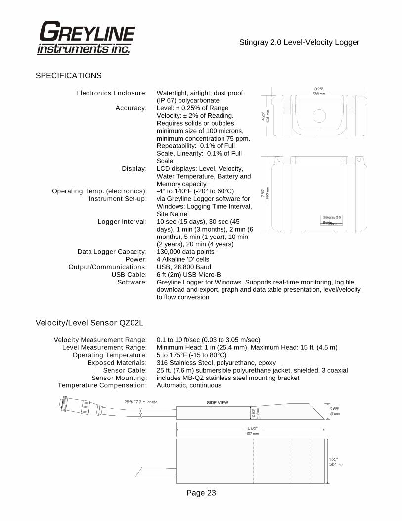
SPECIFICATIONS
Electronics Enclosure: Watertight, airtight, dust proof(IP 67) polycarbonate
Accuracy: Level: ± 0.25% of RangeVelocity: ± 2% of Reading.Requires solids or bubblesminimum size of 100 microns,minimum concentration 75 ppm.Repeatability: 0.1% of FullScale, Linearity: 0.1% of FullScale
Display: LCD displays: Level, Velocity,Water Temperature, Battery andMemory capacity
Operating Temp. (electronics): -4° to 140°F (-20° to 60°C)Instrument Set-up: via Greyline Logger software for
Windows: Logging Time Interval,Site Name
Logger Interval: 10 sec (15 days), 30 sec (45days), 1 min (3 months), 2 min (6months), 5 min (1 year), 10 min(2 years), 20 min (4 years)
Data Logger Capacity: 130,000 data pointsPower: 4 Alkaline 'D' cells
Output/Communications: USB, 28,800 BaudUSB Cable: 6 ft (2m) USB Micro-B
Software: Greyline Logger for Windows. Supports real-time monitoring, log filedownload and export, graph and data table presentation, level/velocityto flow conversion
Velocity/Level Sensor QZ02L
Velocity Measurement Range: 0.1 to 10 ft/sec (0.03 to 3.05 m/sec)Level Measurement Range: Minimum Head: 1 in (25.4 mm). Maximum Head: 15 ft. (4.5 m)
Operating Temperature: 5 to 175°F (-15 to 80°C)Exposed Materials: 316 Stainless Steel, polyurethane, epoxy
Sensor Cable: 25 ft. (7.6 m) submersible polyurethane jacket, shielded, 3 coaxialSensor Mounting: includes MB-QZ stainless steel mounting bracket
Temperature Compensation: Automatic, continuous