STD-T64-C.S0058-0 v1.0
120
ARIB STD-T64-C.S0058-0 v1.0 Over The Air Interoperability Specification for cdma2000 Air Interface Refer to "Industrial Property Rights (IPR)" in the preface of ARIB STD-T64 for Related Industrial Property Rights. Refer to "Notice" in the preface of ARIB STD-T64 for Copyrights
Transcript of STD-T64-C.S0058-0 v1.0
ARIB STD-T64-C.S0058-0 v1.0
Over The Air Interoperability Specification for cdma2000 Air Interface
Refer to "Industrial Property Rights (IPR)" in the preface of ARIB STD-T64 for Related Industrial
Property Rights. Refer to "Notice" in the preface of ARIB STD-T64 for Copyrights
Original Specification 1
2
3
4
This standard, ARIB STD-T64-C.S0058-0 v1.0, was prepared by 3GPP2-WG of Association of
Radio Industries and Businesses (ARIB) based upon the 3GPP2 specification, C.S0058-0 v1.0.
Modification to the original specification 5
6
7
None.
Notes 8
9
10
None.
3GPP2 C.S0058-0
Version 1.0
Version Date: January 2006
OVER THE AIR INTEROPERABILITY SPECIFICATION FOR cdma2000 AIR INTERFACE
COPYRIGHT NOTICE 3GPP2 and its Organizational Partners claim copyright in this document and individual Organizational Partners may copyright and issue documents or standards publications in individual Organizational Partner's name based on this document. Requests for reproduction of this document should be directed to the 3GPP2 Secretariat at [email protected]. Requests to reproduce individual Organizational Partner's documents should be directed to that Organizational Partner. See www.3gpp2.org for more information.

2 3 4 5 6 7 8 9
10 11 12 13 14 15 16 17 18 19 20 21 22 23 24 25 26 27 28 29 30 31 32 33 34 35 36 37 38 39 40 41 42 43 44 45 46 47 48 49 50 51 52 53 54 55 56 57 58 59 60
No Text.
ii
3GPP2 C.S0058-0 v1.0
CONTENTS 1 Introduction.......................................................................................................................................... 1-1
1.1 General Description ............................................................................................................... 1-1 1.2 Testing Objective................................................................................................................... 1-1 1.3 Execution Strategy................................................................................................................. 1-1 1.4 References.............................................................................................................................. 1-2 1.5 Definitions, Symbols and Abbreviations ............................................................................... 1-3
2 Basic Air Interface Tests ...................................................................................................................... 2-1 2.1 Mobile Station Response to Status Request Message ............................................................ 2-1 2.2 Reverse traffic channel DTMF tone signaling ....................................................................... 2-2 2.3 Service configuration and negotiation ................................................................................... 2-3 2.4 Release order on access channel ............................................................................................ 2-7
3 Handoff Tests ....................................................................................................................................... 3-1 3.1 Soft handoff ........................................................................................................................... 3-1 3.2 Hard handoff between frequencies in the same band class .................................................... 3-2 3.3 Hard Handoff from CDMA to Analog................................................................................... 3-3 3.4 Hard handoff between different band classes ........................................................................ 3-4 3.5 Handoff on same frequency with different radio configurations ........................................... 3-4 3.6 Hard handoff while in the waiting for mobile station answer substate .................................. 3-6
4 Power Control Tests ............................................................................................................................. 4-1 4.1 Forward traffic channel power control................................................................................... 4-1 4.2 Fast forward power control for Voice and Data..................................................................... 4-2
5 Subscriber Calling Features Tests ........................................................................................................ 5-1 5.1 Call Forwarding ..................................................................................................................... 5-1 5.2 Three-way calling .................................................................................................................. 5-4 5.3 Call waiting............................................................................................................................ 5-5 5.4 Caller ID ................................................................................................................................ 5-7 5.5 Call Waiting Call Back .......................................................................................................... 5-8 5.6 Voice Privacy......................................................................................................................... 5-9 5.7 CDMA Authentication..........................................................................................................5-10 5.8 Voice Mail Notification ........................................................................................................5-11 5.9 Voice Mail Retrieval.............................................................................................................5-12 5.10 No Answer with Release Order ............................................................................................5-13 5.11 Mobile Station originated SMS.............................................................................................5-13 5.12 Mobile Station originated SMS in Conversation Substate....................................................5-14 5.13 Mobile Station terminated SMS............................................................................................5-15 5.14 Mobile Station terminated SMS in Conversation Substate ...................................................5-16
6 High-speed Packet Data ....................................................................................................................... 6-1
iii
3GPP2 C.S0058-0 v1.0 1 2
6.1 Forward file transfer............................................................................................................... 6-1 3 4 5 6 7 8 9
10 11 12 13 14 15 16 17 18 19 20 21 22 23 24 25 26 27 28 29 30 31 32 33 34 35 36 37 38 39 40 41 42 43 44 45 46 47 48 49 50 51 52 53 54 55 56 57 58
6.2 Reverse file transfer ............................................................................................................... 6-2 6.3 Bidirectional file transfer ....................................................................................................... 6-2 6.4 Soft handoff of fundamental channel and supplemental channels ......................................... 6-3 6.5 Soft handoff of fundamental channel only............................................................................. 6-4 6.6 Hard handoff to HSPD-capable system ................................................................................. 6-6 6.7 HSPD PPP or IP Expiration ................................................................................................... 6-7 6.8 HSPD Mobile IP Inter-PDSN Active Handoff....................................................................... 6-8 6.9 HSPD Mobile IP Inter-PDSN Dormant Idle Handoff............................................................ 6-8 6.10 HSPD Ping while Dormant .................................................................................................... 6-9 6.11 HSPD Call Drop or Temporary Loss of Service.................................................................. 6-10 6.12 HSPD and SMS.................................................................................................................... 6-11
7 Packet Data Services Tests................................................................................................................... 7-1 7.1 File Transfer........................................................................................................................... 7-1 7.2 Simple IP Establishment ........................................................................................................ 7-1 7.3 Registration Lifetime Processing ........................................................................................... 7-2
8 Position Determination Tests ............................................................................................................... 8-1 8.1 Position Determination .......................................................................................................... 8-1
9 HRPD Tests.......................................................................................................................................... 9-1 9.1 HRPD Acquisition and Idle Mode Operation ........................................................................ 9-1 9.2 AT initiated HRPD Session Configuration ............................................................................ 9-1 9.3 HRPD Session Configuration and Management with Subnet change.................................... 9-2 9.4 HRPD keep alive mechanism................................................................................................. 9-3 9.5 Preferred Control Channel Cycle (PCCC) Negotiation.......................................................... 9-3 9.6 Address Management............................................................................................................. 9-4 9.7 Access Authentication (AN Authentication).......................................................................... 9-5 9.8 DH Key Exchange and SHA-1 Authentication...................................................................... 9-6 9.9 HRPD Control Channel Monitoring and Overhead Message Updates .................................. 9-7 9.10 HRPD Location Update Protocol tests................................................................................... 9-8 9.11 Idle State Channel Hashing.................................................................................................... 9-8 9.12 Data Call Origination and Termination.................................................................................. 9-9 9.13 Soft handoffs (Sectors from same cell) ................................................................................ 9-11 9.14 Soft handoffs (Sectors from different cells) ......................................................................... 9-11 9.15 Simple IP Establishment ...................................................................................................... 9-12 9.16 Registration Lifetime Processing ......................................................................................... 9-13
10 Concurrent Services ........................................................................................................................... 10-1
59 60
iv
10.1 Set up Mobile Station Originated Data Call while Voice Call or Teleservice Call is in Progress................................................................................................................................ 10-1
10.2 Set up Mobile Station terminated Data Call while Voice Call or Teleservice Call is in Progress................................................................................................................................ 10-3
3GPP2 C.S0058-0 v1.0 1 2
10.3 Set up Mobile Station Originated Voice Call while Data Call or Teleservice Call is in Progress.................................................................................................................................10-6
3 4 5 6 7 8 9 10 11 12 13 14 15 16 17 18 19 20 21 22 23 24 25 26 27 28 29 30 31 32 33 34 35 36 37 38 39 40 41 42 43 44 45 46 47 48 49 50 51 52 53 54 55 56 57 58
10.4 Set up Mobile Station terminated Voice Call while Data Call or Teleservice Call is in Progress.................................................................................................................................10-8
10.5 Mobile Station Release of a Single Call While Voice and Data Calls are in Progress .......10-11 10.6 Base Station Release of a Single Call While Voice and Data Calls are in Progress ...........10-13 10.7 Correct Handling of Call Control Signaling .......................................................................10-16 10.8 Release A Mobile Station in Concurrent Calls with a Release A Base Station Hand off
to Pre-Release A Base Station ............................................................................................10-21
59 60
v

3GPP2 C.S0058-0 v1.0 1 2 3 4 5 6 7 8 9
10 11 12 13 14 15 16 17 18 19 20 21 22 23 24 25 26 27 28 29 30 31 32 33 34 35 36 37 38 39 40 41 42 43 44 45 46 47 48 49 50 51 52 53 54 55 56 57 58
No Text
59 60
vi

3GPP2 C.S0058-0 v1.0
LIST OF FIGURES None
vii

3GPP2 C.S0058-0 v1.0 1 2 3 4 5 6 7 8 9
10 11 12 13 14 15 16 17 18 19 20 21 22 23 24 25 26 27 28 29 30 31 32 33 34 35 36 37 38 39 40 41 42 43 44 45 46 47 48 49 50 51 52 53 54 55 56 57 58
No text.
59 60
viii

3GPP2 C.S0058-0 v1.0
LIST OF TABLES
Table 1 Reverse power control subchannel configurations ................................................................................ 4-2
ix

3GPP2 C.S0058-0 v1.0 1 2 3 4 5 6 7 8 9
10 11 12 13 14 15 16 17 18 19 20 21 22 23 24 25 26 27 28 29 30 31 32 33 34 35 36 37 38 39 40 41 42 43 44 45 46 47 48 49 50 51 52 53 54 55 56 57 58
No text.
59 60
x
3GPP2 C.S0058-0 v1.0
FOREWORD (This foreword is not part of this Standard.)
This Specification was prepared by Technical Specification Group C of the Third Generation Partnership Project 2 (3GPP2). This Specification is the first revision of the document and tests over-the-air interoperability for CDMA mobile stations or access terminals. Other Interoperability test specifications such as C.S0044-0 (Interoperability Specification for cdma2000®1 Air Interface) are meant to test interoperability in a cabled environment.
SCOPE This specification defines air interface interoperability tests for CDMA mobile stations or access terminals.
1 cdma2000® is the trademark for the technical nomenclature for certain specifications and standards of the Organizational Partners (OPs) of 3GPP2. Geographically (and as of the date of publication), cdma2000® is a registered trademark of the Telecommunications Industry Association (TIA-USA) in the United States.
xi

3GPP2 C.S0058-0 v1.0 1 2 3 4 5 6 7 8 9
10 11 12 13 14 15 16 17 18 19 20 21 22 23 24 25 26 27 28 29 30 31 32 33 34 35 36 37 38 39 40 41 42 43 44 45 46 47 48 49 50 51 52 53 54 55 56 57 58
No text.
59 60
xii
3GPP2 C.S0058-0 v1.0 1 2 3 4 5 6 7 8 9 10 11 12 13 14 15 16 17 18 19 20 21 22 23 24 25 26 27 28 29 30 31 32 33 34 35 36 37 38 39 40 41 42 43 44 45 46 47 48 49 50 51 52 53 54 55 56 57 58
1 Introduction
1.1 General Description This document defines air interface interoperability tests for CDMA mobile stations/access terminals and base stations/access networks. This document defines test cases for cdma2000 1x base stations and mobile stations with protocol revision equal to or less than seven and/or revision 0 of [8].
In this document, ‘mobile station’ or ‘access terminal’ refers to a subscriber terminal, handset, PDA, wireless local loop unit, or any other CDMA subscriber terminal that communicates with the base station at the air interface. ‘Base station’ or ‘access network’ refers to the composite functionality of the base station and connected network elements. These tests are performed over-the-air in a live network environment.
1.2 Testing Objective The objective of this document is to provide tests to demonstrate the interoperability of mobile stations/access terminals and base stations/access networks compliant with the cdma2000 family of standards. References to the applicable standard functionality are listed in the traceability section of each test case.
1.3 Execution Strategy All the test cases are performed over-the-air. Base stations should be configured for normal operation. Multiple test cases may be executed together as a single test case execution.
Unless specified otherwise, all test cases shall be executed in favorable conditions. A favorable channel condition shall allow the BS to receive valid messages from the MS and the MS to receive valid messages from the BS with high probability. A favorable condition should consist of both a good channel condition and low network congestion. Pilot pollution, electromagnetic interference and jammers should be kept to a minimum in a favorable channel condition. The received signal strengths should be between -35dBm and -75dBm with Pilot Ec/Io greater than -10dB. The Pilot Ec/Io requirement is not applicable in handoff cases.
All verification steps in the “Method of Measurement” section of a test are requirements for that test case in addition to the requirements stated in the “Minimum Standard” section. Each test case should be executed as completely as possible according to the “Method of Measurement” section even if any of the verification steps fail.
A test case failure does not necessarily indicate a failure of a mobile station or a base station. In some scenarios a test case may fail due to network congestion or poor channel conditions. If a test case fails it is recommended that the test case be repeated preferably under different conditions such as a different time, a different location, and a different infrastructure. More analysis to determine the reason for failure may be required e.g. analyze test logs, perform a similar test case in cabled environment etc.
59 60
1-1
3GPP2 C.S0058-0 v1.0 1 2 3 4 5 6 7 8 9
10 11 12 13 14 15 16 17 18 19 20 21 22 23 24 25 26 27 28 29 30 31 32 33 34 35 36 37 38 39 40 41 42 43 44 45 46 47 48 49 50 51 52 53 54 55 56 57 58
1.4 References
The following standards and documents contain provisions, which, through reference in this text, constitute provisions of this specification. At the time of publication, the editions indicated were valid. All standards are subject to revision, and parties to agreements based on this standard are encouraged to investigate the possibility of applying the most recent editions of the standards indicated below. Reference [6] is informative reference, while all other references are normative references.
[1] 3GPP2 C.S0002-A, Physical Layer Standard for cdma2000 Spread Spectrum Systems
[2] 3GPP2 C.S0004-A, Signaling Link Access Control (LAC) Standard for cdma2000 Spread Spectrum Systems
[3] 3GPP2 C.S0005-A, Upper Layer (Layer 3) Signaling Standard for cdma2000 Spread Spectrum Systems
[4] 3GPP2 C.S0015-0, Short Message Services for Wideband Spread Spectrum Cellular Systems
[5] 3GPP2 C.S0017-0, Data Service Options for Wideband Spread Spectrum Systems
[6] 3GPP2 C.R1001-E, Administration of Parameter Value Assignment for cdma2000 Spread Spectrum Standards (Informative Reference)
[7] 3GPP2 S.R0006 Wireless Features Description
[8] 3GPP2 C.S0024-0, cdma2000 High Rate Packet Data Air Interface Specification
[9] 3GPP2 C.S0022-0, Position Determination Service Standards for Dual Mode Spread Spectrum Systems
[10] 3GPP2 A.S0007-A, Interoperability Specification (IOS) for High Rate Packet Data (HRPD) Access Network Interfaces
[11] 3GPP2 C.S0037-0, Signaling Conformance Specification for cdma2000 Wireless IP Networks
[12] 3GPP2 C.S0057-0, Band Class Specification for cdma2000 Spread Spectrum Systems
59 60
1-2
3GPP2 C.S0058-0 v1.0 1 2 3 4 5 6 7 8 9 10 11 12 13 14 15 16 17 18 19 20 21 22 23 24 25 26 27 28 29 30 31 32 33 34 35 36 37 38 39 40 41 42 43 44 45 46 47 48 49 50 51 52 53 54 55 56 57 58
1.5 Definitions, Symbols and Abbreviations
1.5.1 Supplementary Terms and Definitions Access Channel. A Reverse CDMA Channel used by mobile stations for communicating to the base station. The Access Channel is used for short signaling message exchanges such as call originations, responses to pages, and registrations. The Access Channel is a slotted random access channel.
Acknowledgment. A Layer 2 response by the mobile station or the base station confirming that a signaling message was received correctly.
Action Time. The time at which the action implied by a message should take effect.
Active Set. The set of pilots associated with the CDMA Channels containing Forward Traffic Channels assigned to a particular mobile station.
AN. Access Network
AT. Access Terminal
Authentication. A procedure used by a base station to validate a mobile station’s identity.
AWGN. Additive White Gaussian Noise.
Band Class. A set of frequency channels and a numbering scheme for these channels as described in [12].
Base Station. A fixed station used for communicating with mobile stations. In this document, the term base station refers to the entire cellular system infrastructure including transceiver equipment and Mobile Switching Center.
Bps. Bits per second.
BS. See base station.
Candidate Set. The set of pilots that have been received with sufficient strength by the mobile station to be successfully demodulated, but have not been placed in the Active Set by the base station. See also Active Set, Neighbor Set, and Remaining Set.
CDMA. See Code Division Multiple Access.
CDMA Channel. The set of channels transmitted between the base station and the mobile stations within a given CDMA frequency assignment. See also Forward CDMA Channel and Reverse CDMA Channel.
CFNA. Call Forwarding No Answer
Chip. See PN Chip.
Code Channel. A subchannel of a Forward CDMA Channel. A Forward CDMA Channel contains 64 code channels. Code channel zero is assigned to the Forward pilot channel. Code channels 1 through 7 may be assigned either to the Paging Channels or to the Traffic Channels. Code channel 32 may be assigned either to a Sync Channel or to a Traffic Channel. The remaining code channels may be assigned to Traffic Channels.
Code Division Multiple Access (CDMA). A technique for spread-spectrum multiple-access digital communications that creates channels through the use of unique code sequences.
59 60
1-3
Configuration Change Indicator. A one-bit datum, sent on the Quick Paging Channel. Appearance of the Configuration Change Indicator in the Quick Paging Channel serves to alert a slotted mode mobile station, operating in the idle state, that, after performing an idle handoff, it should monitor the Paging Channel, in order to determine if it should update its stored parameters.
3GPP2 C.S0058-0 v1.0 1 2 3 4 5 6 7 8 9
10 11 12 13 14 15 16 17 18 19 20 21 22 23 24 25 26 27 28 29 30 31 32 33 34 35 36 37 38 39 40 41 42 43 44 45 46 47 48 49 50 51 52 53 54 55 56 57 58
CPN. Calling Party Number
dBm. A measure of power expressed in terms of its ratio to one milliwatt.
Dedicated Control Channel. A portion of a Traffic Channel (Forward or Reverse) that carries a combination of user data, signaling, and power control information.
DTMF. See Dual-Tone Multifrequency.
Dual-Tone Multifrequency (DTMF). Signaling by the simultaneous transmission of two tones, one from a group of low frequencies and another from a group of high frequencies. Each group of frequencies consists of four frequencies.
Eb. Average energy per information bit for the Sync Channel, Paging Channel, or Forward Traffic Channel at the mobile station antenna connector.
Eb/No. Energy-per-bit-to noise-per-hertz ratio.
Eb/Nt. The ratio of the combined received energy per bit to the effective noise power spectral density for the Sync Channel, Paging Channel, or Forward Traffic Channel at the mobile station antenna connector.
Ec. Average energy per PN chip for the Forward pilot channel, Sync Channel, Paging Channel, Forward Traffic Channel, power control subchannel.
Ec/Io. A notation used to represent a dimensionless ratio of the average power of some code-distinguished CDMA signal channel, typically a pilot, to the total power comprised of signal plus interference, within the signal bandwidth. It is usually expressed in dB units.
Ec/Ior. The ratio of the average transmit energy per PN chip for the Forward pilot channel, Sync Channel, Paging Channel, Forward Traffic Channel, power control subchannel,to the total transmit power spectral density.
ESN. Electronic Serial Number.
FA. Foreign Agent.
f-csch. Forward common signaling logical channel.
f-dsch. Forward dedicated signaling logical channel.
FER. Frame Error Rate of Forward Traffic Channel. The value of FER may be estimated by using Service Option 2, 9, 30, or 31 (see TIA/EIA-126-C).
Flash. An indication sent on the CDMA Channel indicating that the receiver is to invoke special processing.
Forward CDMA Channel. A CDMA Channel from a base station to mobile stations. The Forward CDMA Channel contains one or more code channels that are transmitted on a CDMA frequency assignment using a particular pilot PN offset. The code channels are associated with the Forward pilot channel, Sync Channel, Paging Channels, and Traffic Channels. The Forward CDMA Channel always carries a Forward pilot channel and may carry up to one Sync Channel, up to seven Paging Channels, and up to 63 Traffic Channels, as long as the total number of channels, including the Forward pilot channel, is no greater than 64.
Forward Fundamental Channel (F-FCH). A portion of a Forward Traffic Channel that can carry a combination of primary data, secondary data, signaling, and power control information.
59 60
1-4
Forward Supplemental Channel (F-SCH). An optional portion of a Forward Traffic Channel (Radio Configurations 3 and above) that operates in conjunction with a Fundamental Channel and or the Dedicated Control Channel in that Traffic Channel, and (optionally) with other Supplemental Channels to provide higher data rate services.
Forward Traffic Channel. A code channel used to transport user and signaling traffic from a base station to a mobile station.

3GPP2 C.S0058-0 v1.0 1 2 3 4 5 6 7 8 9 10 11 12 13 14 15 16 17 18 19 20 21 22 23 24 25 26 27 28 29 30 31 32 33 34 35 36 37 38 39 40 41 42 43 44 45 46 47 48 49 50 51 52 53 54 55 56 57 58
FPC. Forward Power Control.
Frame. A basic timing interval in the system. For the Access Channel and Paging Channel a frame is 20 ms long. For the Traffic Channel, the frame may be 20 ms or 5 ms long. For the Sync Channel, a frame is 26.666... ms long.
Frame Offset. A time skewing of Traffic Channel frames from System Time in integer multiples of 1.25 ms. The maximum frame offset is 18.75 ms.
FTP. File Transfer Protocol
GHz. Gigahertz (109 Hertz).
Good Frames. Frames not classified as bad frames. See also Bad Frames.
Handoff. The act of transferring communication with a mobile station from one base station to another.
Hard Handoff. A handoff characterized by a temporary disconnection of the Traffic Channel. Hard handoffs occur when the mobile station is transferred between disjoint Active Sets, the CDMA frequency assignment changes, the frame offset changes, or the mobile station is directed from a CDMA Traffic Channel to an AMPS voice channel. See also Soft Handoff.
Hash Function. A function used by the mobile station to select one out of N available resources. The hash function distributes the available resources uniformly among a random sample of mobile stations.
HRPD. High Rate Packet Data.
HSPD. High Speed Packet Data.
Idle Handoff. The act of transferring reception of the Paging Channel from one base station to another, when the mobile station is in the Mobile Station Idle State.
Io. The total received power spectral density, including signal and interference, as measured at the mobile station antenna connector.
Ioc. The power spectral density of a band-limited white noise source (simulating interference from other cells) as measured at the mobile station antenna connector.
Ior. The total transmit power spectral density of the Forward CDMA Channel at the base station antenna connector.
Îor. The received power spectral density of the Forward CDMA Channel as measured at the mobile station antenna connector.
ITU. International Telecommunication Union
LAC. Link Access Control
Layering. A method of organization for communication protocols in which the transmitted or received information is transferred in pipeline fashion, within each station, in well-defined encapsulated data units between otherwise decoupled processing entities (“layers”). A layer is defined in terms of its communication protocol to a peer layer in another entity and the services it offers to the next higher layer in its own entity.
Layer 1. Layer 1 provides for the transmission and reception of radio signals between the base station and the mobile station. Also see Physical Layer.
Layer 2. Layer 2 provides for the correct transmission and reception of signaling messages, including partial duplicate detection. Layer 2 makes use of the services provided by Layer 1.
59 60
1-5
Layer 3. Layer 3 provides the control messaging for the cellular or PCS telephone system. Layer 3 originates and terminates signaling messages according to the semantics and timing of the
3GPP2 C.S0058-0 v1.0 1 2 3 4 5 6 7 8 9
10 11 12 13 14 15 16 17 18 19 20 21 22 23 24 25 26 27 28 29 30 31 32 33 34 35 36 37 38 39 40 41 42 43 44 45 46 47 48 49 50 51 52 53 54 55 56 57 58
communication protocol between the base station and the mobile station. Layer 3 makes use of the services provided by Layer 2.
Long Code. A PN sequence with period (242) - 1 that is used for scrambling on the Forward CDMA Channel and spreading on the Reverse CDMA Channel. The long code uniquely identifies a mobile station on both the Reverse Traffic Channel and the Forward Traffic Channel. The long code provides limited privacy. The long code also separates multiple Access Channels on the same CDMA Channel. See also Public Long Code and Private Long Code.
Long Code Mask. A 42-bit binary number that creates the unique identity of the long code. See also Public Long Code, Private Long Code, Public Long Code Mask, and Private Long Code Mask.
MOB_P_REV. Protocol revision number supported by a mobile station.
Mobile Station (MS). A station that communicates with a base station while in motion or during halts at unspecified points.
Mobile Station Originated Call. A call originating from a mobile station.
Mobile Station Terminated Call. A call received by a mobile station (not to be confused with a disconnect or call release).
MS. See Mobile Station
MSIN. See Mobile Station Identification Number.
Neighbor Set. The set of pilots associated with the CDMA Channels that are probable candidates for handoff. Normally, the Neighbor Set consists of the pilots associated with CDMA Channels that cover geographical areas near the mobile station. See also Active Set, Candidate Set, Remaining Set, and Private Neighbor Set.
Network. A network is a subset of a cellular or PCS system, such as an area-wide cellular network, a private group of base stations, or a group of base stations set up to handle a special requirement. A network can be as small or as large as needed, as long as it is fully contained within a system. See also System.
Network Identification (NID). A number that uniquely identifies a network within a cellular or PCS system. See also System Identification.
NID. See Network Identification.
Nt. The effective noise power spectral density at the mobile station antenna connector.
NULL. Any value that is not in the specified range of a field.
Order. A type of message that contains control codes for either the mobile station or the base station.
Overhead Message. A message sent by the base station on the Paging Channel to communicate base-station-specific and system-wide information to mobile stations.
P_REV. Protocol revision level supported by a base station
P_REV_IN_USE. Protocol revision level currently in use by a mobile station
Packet. The unit of information exchanged between the service option applications of the base station and the mobile station.
Paging. The act of seeking a mobile station when a call has been placed to that mobile station.
Paging Channel. A code channel in a CDMA channel used for transmission of control information and pages from a base station to a mobile station.
59 60
1-6
Paging Channel Slot. An 80 ms interval on the Paging Channel. Mobile stations operating in the slotted mode are assigned specific slots in which they monitor messages from the base station.
Paging Ec. Average energy per PN chip for the Paging Channel.
3GPP2 C.S0058-0 v1.0 1 2 3 4 5 6 7 8 9 10 11 12 13 14 15 16 17 18 19 20 21 22 23 24 25 26 27 28 29 30 31 32 33 34 35 36 37 38 39 40 41 42 43 44 45 46 47 48 49 50 51 52 53 54 55 56 57 58
IorEc Paging
. The ratio of the average transmit energy per PN chip for the Paging Channel to the total
transmit power spectral density.
Paging Indicator. A one-bit datum, sent on the Quick Paging Channel. Quick paging indicators are associated with mobile stations, in pairs, via a hashing algorithm. Appearance of both of its indicators in its assigned Quick Paging Channel slot serves to alert a slotted mode mobile station, operating in the idle state, that it should monitor the Paging Channel starting in the next slot. See also Quick Paging Channel.
Parameter-Change Registration. A registration method in which the mobile station registers when certain of its stored parameters change.
PCCC. Preferred Control Channel Cycle.
PCS. See Personal Communications Services.
PCS System. See Personal Communications Services System.
Personal Communications Services (PCS). A family of mobile and portable radio communications services for individuals and businesses that may be integrated with a variety of competing networks. Broadcasting is prohibited and fixed operations are to be ancillary to mobile operations.
Personal Communication Services System. A configuration of equipment that provides PCS radiotelephone services.
Personal Communications Switching Center (PCSC). See Mobile Switching Center (MSC).
Physical Layer. The part of the communication protocol between the mobile station and the base station that is responsible for the transmission and reception of data. The physical layer in the transmitting station is presented a frame by the multiplex sublayer and transforms it into an over-the-air waveform. The physical layer in the receiving station transforms the waveform back into a frame and presents it to the multiplex sublayer above it.
PI. See Paging Indicator.
Pilot Ec. Average energy per PN chip for the Forward pilot channel.
IoEc Pilot . The ratio of the combined pilot energy per chip, Ec, to the total received power spectral
density (noise and signals), Io, of at most K usable multipath components at the mobile station antenna connector (see 1.4). K is the number of demodulating elements supported by the mobile station.
IorEc Pilot . The ratio of the average transmit energy per PN chip for the Forward pilot channel to the
total transmit power spectral density.
Pilot PN Sequence Offset. The time offset of a Forward Pilot Channel from CDMA System time, as transmitted by the base station, expressed modulo the pilot period.
Pilot PN Sequence Offset Index. The pilot PN sequence offset in units of 64 PN chips of a Forward Pilot Channel, relative to the zero offset pilot PN sequence.
Pilot Strength. The ratio of pilot power to total power in the signal bandwidth of a CDMA Forward or Reverse Channel. See also Ec/Io.
PN. Pseudonoise.
59 60
1-7
PN Chip. One bit in a PN sequence, or the time duration of such a bit. It corresponds to the smallest modulation interval in a CDMA system.
3GPP2 C.S0058-0 v1.0 1 2 3 4 5 6 7 8 9
10 11 12 13 14 15 16 17 18 19 20 21 22 23 24 25 26 27 28 29 30 31 32 33 34 35 36 37 38 39 40 41 42 43 44 45 46 47 48 49 50 51 52 53 54 55 56 57 58
PN Sequence. Pseudo-random noise sequence. A deterministic, periodic binary sequence having limited statistical similarity to a Bernoulli (coin-tossing).
Power Control Bit. A bit sent in every 1.25 ms interval on the Forward Traffic Channel that signals the mobile station to increase or decrease its transmit power.
IorEc ControlPower . The ratio of the average transmit energy per PN chip for the power control
subchannel to the total transmit power spectral density.
Power Control Group. A 1.25 ms interval on the Forward Traffic Channel and the Reverse Traffic Channel. See also Power Control Bit.
Power-Down Registration. An autonomous registration method in which the mobile station registers on power-down.
Power-Up Registration. An autonomous registration method in which the mobile station registers on power-up.
PPP. Point-to-Point Protocol.
Primary Traffic. The main traffic stream carried between the mobile station and the base station on the Traffic Channel. See also Secondary Traffic and Signaling Traffic.
Private Long Code. The long code characterized by the private long code mask. See also Long Code.
Private Long Code Mask. The long code mask used to form the private long code. See also Public Long Code Mask and Long Code.
Private Neighbor Set. The set of pilots associated with the private system base stations that are probable candidates for idle handoff. See also Active Set, Neighbor Set, Remaining Set, and CDMA Tiered Services.
Public Long Code. The long code characterized by the public long code mask.
Public Long Code Mask. The long code mask used to form the public long code. The mask contains a permutation of the bits of the ESN, and also includes the channel number when used for a Supplemental Code Channel. See also Private Long Code Mask and Long Code.
QPCH. See Quick Paging Channel.
Quick Paging. A feature that permits mobile stations to further conserve battery power beyond the savings achieved by slotted mode operation. See also Paging Indicator and Configuration Change Indicator.
Quick Paging Channel (QPCH). An uncoded, on-off-keyed (OOK) spread spectrum signal sent by base stations to inform slotted mode mobile stations, operating in the idle state, whether to monitor the Paging Channel. See also Quick Paging, Paging Indicator, and Configuration Change Indicator.
Quick Paging Channel Slot. An 80 ms interval on the Quick Paging Channel. See also Paging Indicator and Configuration Change Indicator.
RATI. Random Access Terminal Identifier. See [8].
r-csch. Reverse common signaling logical channel.
r-dsch. Reverse dedicated signaling logical channel.
Radio Configuration (RC). A set of Forward Traffic Channel and Reverse Traffic Channel transmission formats that are characterized by physical layer parameters such as transmission rates, modulation characteristics and spreading rate.
59 60
1-8
RC. See Radio configuration.
3GPP2 C.S0058-0 v1.0 1 2 3 4 5 6 7 8 9 10 11 12 13 14 15 16 17 18 19 20 21 22 23 24 25 26 27 28 29 30 31 32 33 34 35 36 37 38 39 40 41 42 43 44 45 46 47 48 49 50 51 52 53 54 55 56 57 58
Registration. The process by which a mobile station identifies its location and parameters to a base station.
Registration Zone. A collection of one or more base stations treated as a unit when determining whether a mobile station should perform zone-based registration. See also User Zone, with which it should not be confused.
Relay Mode. Relay Layer Rm Interface Protocol Option as defined in [5].
Release. A process that the mobile station and base station use to inform each other of call disconnect.
Remaining Set. The set of all allowable pilot offsets as determined by PILOT_INC, excluding the pilot offsets of the pilots in the Active Set, Candidate Set, and Neighbor Set. See also Active Set, Candidate Set, and Neighbor Set.
Request. A layer 3 message generated by either the mobile station or the base station to retrieve information, ask for service, or command an action.
Response. A layer 3 message generated as a result of another message, typically a request.
Reverse CDMA Channel. The CDMA Channel from the mobile station to the base station. From the base station’s perspective, the Reverse CDMA Channel is the sum of all mobile station transmissions on a CDMA frequency assignment.
Reverse Fundamental Channel (R-FCH). A portion of a Reverse Traffic Channel that can carry a combination of primary data, secondary data, signaling, and power control information.
Reverse Pilot Channel (R-PICH). A non-data-bearing direct-sequence spread spectrum signal transmitted by each CDMA mobile station whenever the Enhanced Access Channel, Reverse Common Control Channel, or Reverse Traffic Channel is enabled. The Reverse Pilot Channel allows a base station to acquire the timing of the Reverse CDMA Channel and provides a phase reference for coherent demodulation. The Reverse Pilot Channel may be transmitted either continuously or in gated mode.
Reverse Supplemental Channel (R-SCH). An optional portion of a Reverse Traffic Channel (Radio Configurations 3 and above) that operates in conjunction with a Fundamental Channel and or the Dedicated Control Channel in that Traffic Channel, and (optionally) with other Supplemental Channels to provide higher data rate services.
RF. Radio Frequency.
RLP. Radio Link Protocol.
RRP. Mobile IP Registration Reply.
RRQ. Mobile IP Registration Request.
SCR. Service Configuration Record.
Secondary Traffic. An additional traffic stream that can be carried between the mobile station and the base station on the Traffic Channel. See also Primary Traffic and Signaling Traffic.
Service Configuration. The common attributes used by the mobile station and the base station to build and interpret Traffic Channel frames. A service configuration consists of Forward and Reverse Traffic Channel multiplex options, Forward and Reverse Traffic Channel transmission rates, and service option connections. Service Configuration is signaled via the Service Configuration information record and the Non-Negotiable Service Configuration information record.
Service Negotiation. The procedures used by the mobile station and base station to establish a service configuration. See also Service Option Negotiation.
59 60
1-9
Service Option (SO). A service compatibility of the system. Service options may be applications such as voice, data, or facsimile. See (17).
3GPP2 C.S0058-0 v1.0 1 2 3 4 5 6 7 8 9
10 11 12 13 14 15 16 17 18 19 20 21 22 23 24 25 26 27 28 29 30 31 32 33 34 35 36 37 38 39 40 41 42 43 44 45 46 47 48 49 50 51 52 53 54 55 56 57 58
Service Option Connection. A particular instance or session in which the service defined by a service option is used. Associated with a service option connection are a reference, which is used for uniquely identifying the service option connection, a service option, which specifies the particular type of service in use, a Forward Traffic Channel traffic type, which specifies what type of Forward Traffic Channel traffic is used to support the service option connection, and a Reverse Traffic Channel traffic type, which specifies what type of Reverse Traffic Channel traffic is used by the service option connection.
Service Option Negotiation. The procedures used by the mobile station and base station to establish a service configuration. Service option negotiation is similar to service negotiation, but allows less flexibility for specifying the attributes of the service configuration. See also Service Negotiation.
Shared Secret Data (SSD). A 128-bit pattern stored in the mobile station (in semi-permanent memory) and known by the base station. SSD is a concatenation of two 64-bit subsets: SSD_A, which is used to support the authentication procedures, and SSD_B, which serves as one of the inputs to the process generating the encryption mask and private long code.
Short Message Services (SMS). A suite of services such as SMS Text Delivery, Digital Paging (i.e., Call Back Number - CBN), and Voice Mail Notification (VMN).
SID. See System Identification.
Signaling Traffic. Control messages that are carried between the mobile station and the base station on the Traffic Channel. See also Primary Traffic and Secondary Traffic.
Slotted Mode. An operation mode of the mobile station in which the mobile station monitors only selected slots on the Paging Channel.
SME. Short Message Entity.
SMS. See Short Message Service.
SO. See Service Option.
Soft Handoff. A handoff occurring while the mobile station is in the Mobile Station Control on the Traffic Channel State. This handoff is characterized by commencing communications with a new base station on the same CDMA frequency assignment before terminating communications with the old base station. See Hard Handoff.
SSD. See Shared Secret Data.
Subnet. On TCP/IP networks, subnets are defined as all devices whose IP addresses have the same prefix.
Supplemental Code Channel (SCCH). An optional portion of a Traffic Channel (Forward or Reverse) which operates in conjunction with a Fundamental Channel in that Traffic Channel, and (optionally) with other Supplemental Code Channels to provide higher data rate services. On this channel a combination of primary data, secondary data, or both (but never signaling information) are transmitted.
Supplemental Ec. Average energy per PN chip for one Forward Supplemental Code Channel.
IorEc alSupplement . The ratio of the average transmit energy per PN chip for one Forward
Supplemental to the total transmit power spectral density.
Sync Channel. Code channel 32 in the Forward CDMA Channel, which transports the synchronization message to the mobile station.
59 60
1-10
Sync_Chip_Bit. Number of PN chips per Sync Channel bit, equal to 1024.
Sync Ec. Average energy per PN chip for the Sync Channel.
3GPP2 C.S0058-0 v1.0 1 2 3 4 5 6 7 8 9 10 11 12 13 14 15 16 17 18 19 20 21 22 23 24 25 26 27 28 29 30 31 32 33 34 35 36 37 38 39 40 41 42 43 44 45 46 47 48 49 50 51 52 53 54 55 56 57 58
1-11
IorEc Sync
. The ratio of the average transmit energy per PN chip for the Sync Channel to the total
transmit power spectral density.
System. A system is a cellular telephone service or personal communications service that covers a geographic area such as a city, metropolitan region, county, or group of counties. See also Network.
System Identification (SID). A number uniquely identifying a cellular or PCS system.
System Time. The time reference used by the system. System Time is synchronous to UTC time (except for leap seconds) and uses the same time origin as GPS time. All base stations use the same System Time (within a small error). Mobile stations use the same System Time, offset by the propagation delay from the base station to the mobile station. See also Universal Coordinated Time.
TDSO. Test Data Service Option.
TE2. Terminal Equipment 2.
Timer-Based Registration. A registration method in which the mobile station registers whenever a counter reaches a predetermined value. The counter is incremented an average of once per 80 ms period.
Time Reference. A reference established by the mobile station that is synchronous with the earliest arriving multipath component used for demodulation.
Traffic Channel. A communication path between a mobile station and a base station used for user and signaling traffic. The term Traffic Channel implies a Forward Traffic Channel and Reverse Traffic Channel pair. See also Forward Traffic Channel and Reverse Traffic Channel.
Traffic Channel Preamble. A sequence of all-zero frames that is sent by the mobile station on the Reverse Traffic Channel as an aid to Traffic Channel acquisition.
Traffic Ec. Average energy per PN chip for the Forward Fundamental Channel. For the case when the power control sub-channel is assumed to be transmitted at the same power level used for the
9600 bps or 14400 bps data rate, the following equations apply: For Rate Set 1, it is equal to v11
11+
x (total Forward Fundamental Channel energy per PN chip), where v equals 1 for 9600 bps, v equals 2 for 4800 bps, v equals 4 for 2400 bps, and v equals 8 for 1200 bps traffic data rate. For Rate Set 2,
it is equal to v23
23+
x (total Forward Fundamental Channel energy per PN chip), where v equals 1
for 14400 bps, v equals 2 for 7200 bps, v equals 4 for 3600 bps, and v equals 8 for 1800 bps traffic data rate. The total Forward Fundamental Channel is comprised of traffic data and a power control sub-channel.
IorEc Traffic
. The ratio of the average transmit energy per PN chip for the Forward Traffic Channel to
the total transmit power spectral density.
UATI. Unicast Access Terminal Identifier. See [8].
Unique Challenge-Response Procedure. An exchange of information between a mobile station and a base station for the purpose of confirming the mobile station’s identity. The procedure is initiated by the base station and is characterized by the use of a challenge- specific random number (i.e., RANDU) instead of the random variable broadcast globally (RAND).
Universal Coordinated Time (UTC). An internationally agreed-upon time scale maintained by the Bureau International de l’Heure (BIH) used as the time reference by nearly all commonly available time and frequency distribution systems i.e., WWV, WWVH, LORAN-C, Transit, Omega, and GPS.
59 60
User Zone. An area within which CDMA Tiered Services may be provided. It may correspond to an RF coverage area, or it may be established independent of RF topology. User Zones are classified as
3GPP2 C.S0058-0 v1.0 1 2 3 4 5 6 7 8 9
10 11 12 13 14 15 16 17 18 19 20 21 22 23 24 25 26 27 28 29 30 31 32 33 34 35 36 37 38 39 40 41 42 43 44 45 46 47 48 49 50 51 52 53 54 55 56 57 58
broadcast versus mobile-specific, and as active versus passive. See Broadcast User Zone. Mobile-Specific User Zone, Active User Zone, and Passive User Zone. See also Registration Zone, with which it should not be confused.
UTC. Universal Temps Coordiné. See Universal Coordinated Time.
VMN. Voice Mail Notification.
Voice Privacy. The process by which user voice transmitted over a CDMA Traffic Channel is afforded a modest degree of protection against eavesdropping over the air.
Zone-Based Registration. An autonomous registration method in which the mobile station registers whenever it enters a zone that is not in the mobile station’s zone list. See also User Zone Registration, with which it should not be confused.
Zone Timer. A timer used by the mobile station to remove outdated entries from its list of zones in which it has previously registered.
59 60
1-12
3GPP2 C.S0058-0 v1.0 1 2 3 4 5 6 7 8 9 10 11 12 13 14 15 16 17 18 19 20 21 22 23 24 25 26 27 28 29 30 31 32 33 34 35 36 37 38 39 40 41 42 43 44 45 46 47 48 49 50 51 52 53 54 55 56 57 58
2 Basic Air Interface Tests
2.1 Mobile Station Response to Status Request Message 2.1.1 Definition This test verifies that the mobile station responds to a Status Request Message with an Extended Status Response Message or Status Response Message containing the correct information record(s).
2.1.2 Traceability (See [3] ):
2.6.4.1.2 Service Configuration and Negotiation
2.6.4.1.14 Processing the Service Configuration Record
2.6.4.1.15 Processing the Non-Negotiable Service Configuration Record
2.6.4.2 Traffic Channel Initialization Substate
2.7.1.3.2.4 Origination Message
2.7.1.3.2.5 Page Response Message
2.7.1.3.2.10 Extended Status Response Message
2.7.2.3.2.14 Service Connect Completion Message
2.7.2.3.2.16 Status Response Message
3.6.3.5 Response to Origination Message
3.6.4.1.2 Service Configuration and Negotiation
3.7.2.3.2.15 Status Request Message
3.7.2.3.2.21 Extended Channel Assignment Message
3.7.3.3.2.20 Service Connect Message
3.7.5.7 Service Configuration
3.7.5.20 Non-Negotiable Service Configuration
Annex D Information Records
2.1.3 Method of Measurement 1. Perform an action with the mobile station that will trigger the base station to send a Status
Request Message (e.g. power up, call origination, hard handoff).
2. Verify that the base station sends a Status Request Message.
3. Verify the mobile station responds to Status Request Message with an Extended Status Response Message or Status Response Message with the correct record type and correct information as supported by the mobile station. The record types are specified in [3].
59 60
2-1
3GPP2 C.S0058-0 v1.0 1 2 3 4 5 6 7 8 9
10 11 12 13 14 15 16 17 18 19 20 21 22 23 24 25 26 27 28 29 30 31 32 33 34 35 36 37 38 39 40 41 42 43 44 45 46 47 48 49 50 51 52 53 54 55 56 57 58
1.
2.
3.
4.
5.
6.
7.
8.
2.1.4 Minimum Standard The mobile station shall respond to a Status Request Message with a Status Response Message or an Extended Status Response Message with the correct record type and correct information.
2.2 Reverse traffic channel DTMF tone signaling 2.2.1 Definition
The purpose of this test is to verify mobile station initiated DTMF tones operate properly during a CDMA call.
2.2.2 Traceability (See [3] ):
2.6.10.2 Conversation Substate
2.7.2.3.2.7 Send Burst DTMF Message
2.7.3 Orders
2.2.3 Method of Measurement Configure mobile station to send short DTMF tones (i.e. mobile station sends Send Burst DTMF Message)
Set up a call.
Perform the following steps in succession after the call is set up.
Press and hold any number key for approximately 5 seconds.
Verify mobile station sends Send Burst DTMF Message with the DIGIT field set to the correct value.
Press characters 0123456789#*. Repeat with a random digit order. Note the order of digits to verify sequential order.
Verify that the mobile station sends one or more Send Burst DTMF Messages with the DIGIT fields containing the digits in the correct order.
Configure the mobile station to send long DTMF tones (i.e. the mobile station sends Continuous DTMF Tone Order) and repeat steps 2 to 7. The verification steps should be modified as below: Instead of a Send Burst DTMF Message with DIGIT field, the mobile station sends a Continuous DTMF Tone Order with ORDQ field set to the proper value followed by Continuous DTMF Tone Order with ORDQ field set to ‘11111111’.
2.2.4 Minimum Standard The mobile station shall send DTMF digits to the base station in the order in which the keys were pressed.
59 60
2-2

3GPP2 C.S0058-0 v1.0 1 2 3 4 5 6 7 8 9 10 11 12 13 14 15 16 17 18 19 20 21 22 23 24 25 26 27 28 29 30 31 32 33 34 35 36 37 38 39 40 41 42 43 44 45 46 47 48 49 50 51 52 53 54 55 56 57 58
2.3 Service configuration and negotiation 2.3.1 Definition
This test verifies that the initial service configuration is according to the value specified in the GRANTED_MODE field of the Channel Assignment Message or Extended Channel Assignment Message. This test also verifies the service configuration in use is the one specified by SCR and NN-SCR agreed upon during service negotiation. This test case is applicable to all P_REV_IN_USE except 2.
2.3.2 Traceability (See [3] ):
2.6.4.1.2 MS Service Configuration and Negotiation procedures
2.6.4.1.14 Processing the Service Configuration Record
2.6.4.1.15 Processing the Non-Negotiable Service Configuration Record
2.6.4.2 Traffic Channel Initialization Substate
2.7.1.3.2.4 Origination Message
2.7.1.3.2.5 Page Response Message
2.7.2.3.2.12 Service Request Message
2.7.2.3.2.13 Service Response Message
2.7.2.3.2.14 Service Connect Completion Message
2.7.4.18 Service Configuration information record
3.6.4.1.2 BS Service Configuration and Negotiation procedures
3.7.2.3.2.8 Channel Assignment Message
3.7.2.3.2.21 Extended Channel Assignment Message
3.7.3.3.2.18 Service Request Message
3.7.3.3.2.19 Service Response Message
3.7.3.3.2.20 Service Connect Message
3.7.3.3.2.31 General Handoff Direction Message
3.7.3.3.2.36 Universal Handoff Direction Message
3.7.5.7 Service Configuration information record
3.7.5.20 Non-Negotiable Service Configuration information record
59 60
2-3
3GPP2 C.S0058-0 v1.0 1 2 3 4 5 6 7 8 9
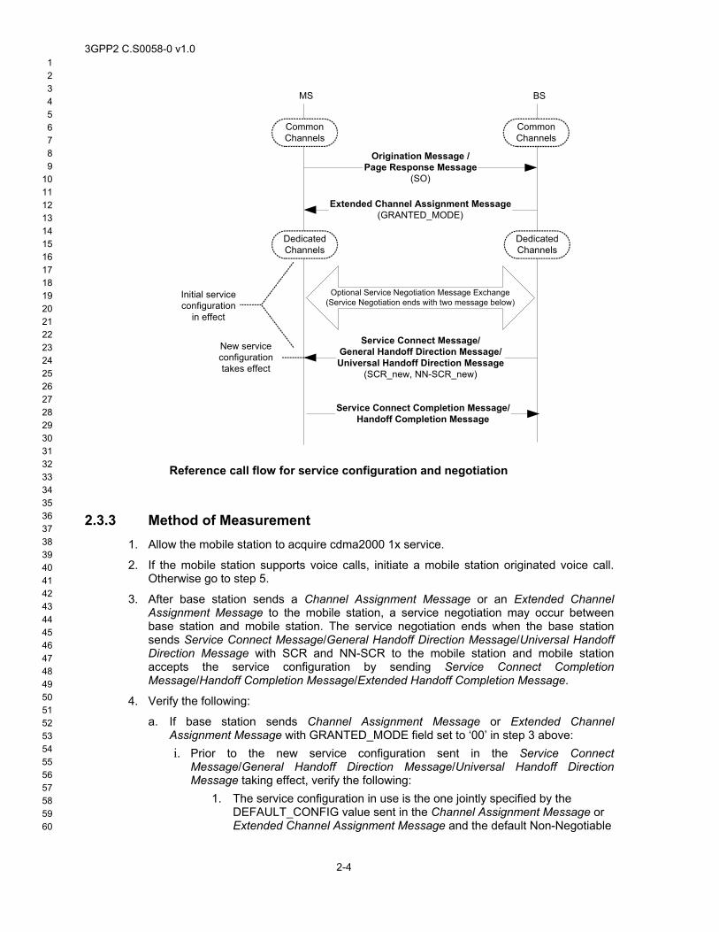
10 11 12 13 14 15 16 17 18 19 20 21 22 23 24 25 26 27 28 29 30 31 32 33 34 35 36 37 38 39 40 41 42 43 44 45 46 47 48 49 50 51 52 53 54 55 56 57 58
BS
DedicatedChannels
MS
DedicatedChannels
Service Connect Message/General Handoff Direction Message/Universal Handoff Direction Message
(SCR_new, NN-SCR_new)
New serviceconfigurationtakes effect
CommonChannels
CommonChannels
Origination Message /Page Response Message
(SO)
Extended Channel Assignment Message(GRANTED_MODE)
Initial serviceconfiguration
in effect
Service Connect Completion Message/Handoff Completion Message
Optional Service Negotiation Message Exchange(Service Negotiation ends with two message below)
Reference call flow for service configuration and negotiation
2.3.3 Method of Measurement 1.
2.
3.
4.
a.
Allow the mobile station to acquire cdma2000 1x service.
If the mobile station supports voice calls, initiate a mobile station originated voice call. Otherwise go to step 5.
After base station sends a Channel Assignment Message or an Extended Channel Assignment Message to the mobile station, a service negotiation may occur between base station and mobile station. The service negotiation ends when the base station sends Service Connect Message/General Handoff Direction Message/Universal Handoff Direction Message with SCR and NN-SCR to the mobile station and mobile station accepts the service configuration by sending Service Connect Completion Message/Handoff Completion Message/Extended Handoff Completion Message.
Verify the following:
If base station sends Channel Assignment Message or Extended Channel Assignment Message with GRANTED_MODE field set to ‘00’ in step 3 above: i. Prior to the new service configuration sent in the Service Connect
Message/General Handoff Direction Message/Universal Handoff Direction Message taking effect, verify the following:
59 60
2-4
1. The service configuration in use is the one jointly specified by the DEFAULT_CONFIG value sent in the Channel Assignment Message or Extended Channel Assignment Message and the default Non-Negotiable
3GPP2 C.S0058-0 v1.0 1 2 3 4 5 6 7 8 9 10 11 12 13 14 15 16 17 18 19 20 21 22 23 24 25 26 27 28 29 30 31 32 33 34 35 36 37 38 39 40 41 42 43 44 45 46 47 48 49 50 51 52 53 54 55 56 57 58
b.
c.
part of the service configuration parameters specified in the Traffic Channel Initialization substate.
ii. When the service configuration sent in the Service Connect Message/General Handoff Direction Message/Universal Handoff Direction Message takes effect, verify the following:
1. The service configuration in use is the one specified by SCR and NN-SCR in the Service Connect Message/General Handoff Direction Message/Universal Handoff Direction Message sent by the base station.
2. Verify user traffic in both directions.
iii. The mobile station sends a Service Connect Completion Message (if the base station sends a Service Connect Message) or a Handoff Completion Message/Extended Handoff Completion Message (if the base station sends a General Handoff Direction Message/Universal Handoff Direction Message) to the base station.
If base station sends Channel Assignment Message or Extended Channel Assignment Message with GRANTED_MODE field set to ‘01’ in step 3 above i. Prior to the new service configuration sent in the Service Connect
Message/General Handoff Direction Message/Universal Handoff Direction Message taking effect, verify the following:
1. If the mobile station received Extended Channel Assignment Message, then verify the following: The service configuration in use is the one jointly specified by the default multiplex option that is derived from the radio configuration corresponding to Table 3.7.2.3.2.21-2 in [3] and the default Non-Negotiable part of the service configuration parameters specified in the Traffic Channel Initialization substate.
2. If the mobile station received Channel Assignment Message, then verify the following: The service configuration in use is the default multiplex option and transmission rates corresponding to the service option requested by the mobile station either in the Origination Message or Page Response Message.
ii. When the new service configuration sent in the Service Connect Message/General Handoff Direction Message/Universal Handoff Direction Message takes effect, verify the following:
1. The service configuration in use is the one specified by SCR and NN-SCR in the Service Connect Message sent by the base station.
2. Verify user traffic in both directions.
iii. The mobile station sends a Service Connect Completion Message (if the base station sends a Service Connect Message) or a Handoff Completion Message/Extended Handoff Completion Message (if the base station sends a General Handoff Direction Message/Universal Handoff Direction Message) to the base station.
If base station sends Channel Assignment Message or Extended Channel Assignment Message with GRANTED_MODE field set to ‘10’ in step 3 above
59 60
2-5
i. Prior to the new service configuration sent in the Service Connect Message/General Handoff Direction Message/Universal Handoff Direction Message taking effect, verify the following:
1. The service configuration in use is the one jointly specified by the default multiplex option that is derived from the radio configuration
3GPP2 C.S0058-0 v1.0 1 2 3 4 5 6 7 8 9
10 11 12 13 14 15 16 17 18 19 20 21 22 23 24 25 26 27 28 29 30 31 32 33 34 35 36 37 38 39 40 41 42 43 44 45 46 47 48 49 50 51 52 53 54 55 56 57 58
d.
e.
corresponding to Table 3.7.2.3.2.21-2 in [3] and the default Non-Negotiable part of the service configuration parameters specified in the Traffic Channel Initialization substate.
ii. When the new service configuration sent in the Service Connect Message/General Handoff Direction Message/Universal Handoff Direction Message takes effect, verify the following:
1. The service configuration in use is the one specified by SCR and NN-SCR in the Service Connect Message sent by the base station.
2. Verify user traffic in both directions.
iii. The mobile station sends a Service Connect Completion Message (if the base station sends a Service Connect Message) or a Handoff Completion Message/Extended Handoff Completion Message (if the base station sends a General Handoff Direction Message/Universal Handoff Direction Message) to the base station.
iv. The mobile station does not send a Service Request Message to the base station prior to the Service Connect Message/General Handoff Direction Message/Universal Handoff Direction Message is received from the base station.
If the base station sends a Service Connect Message to the mobile station with a valid service configuration that is unacceptable to the mobile station based on mobile station capability, verify the following: i. Upon receiving this message, the mobile station sends a Mobile Station Reject
Order with ORDQ set to ‘00000111’. ii. The mobile station does not send a Service Connect Completion Message.
iii. The mobile station does not send a Service Request Message with REQ_PURPOSE set to either ‘0000’ or ‘0001’.
iv. The mobile station does not send a Service Response Message with RESP_PURPOSE set to either ‘0000’ or ‘0001’.
v. The service configuration previously in use continues to be in effect without any interruptions.
vi. Verify user traffic (e.g. Audio) on both directions.
If the base station sends a Service Request Message or Service Response Message with REQ_PURPOSE set to ‘0001’ to reject the service configuration and the base station does not propose another service configuration, verify the following: i. Upon receiving the Service Request Message or Service Response Message
from the base station, the mobile station terminates this service negotiation session. This can be verified by the following conditions:
1. The mobile station does not a send a Service Connect Completion Message to the base station, and
2. The mobile station does not send a Service Response Message or Service Request Message to the base station.
3. The base station does not send a Service Request Message or Service Response Message to the mobile station with the same SERV_REQ_SEQ sent in the rejected Service Request Message or Service Response Message.
59 60
2-6
ii. The service configuration previously in use continues to be in effect without any interruptions.
3GPP2 C.S0058-0 v1.0 1 2 3 4 5 6 7 8 9 10 11 12 13 14 15 16 17 18 19 20 21 22 23 24 25 26 27 28 29 30 31 32 33 34 35 36 37 38 39 40 41 42 43 44 45 46 47 48 49 50 51 52 53 54 55 56 57 58
5. If mobile station supports data calls, initiate a data call and repeat steps 3 through 4.
2.3.4 Minimum Standard The initial service configuration in effect, i.e. service configuration upon establishing dedicated channels and until a Service Connect Message/General Handoff Direction Message/Universal Handoff Direction Message is received from the base station, shall comply with the requirements based on the value specified by the GRANTED_MODE received in the Channel Assignment Message or Extended Channel Assignment Message. For GRANTED_MODE = 10, the mobile station shall not initiate service negotiation until the Service Connect Message is received from the base station. When the new service configuration specified by the Service Connect Message/General Handoff Direction Message/Universal Handoff Direction Message takes effect, user communications shall proceed without interruptions in both directions.
If the service configuration is rejected by the mobile station:
• The mobile station shall terminate the service negotiation session and the service configuration previously in use shall remain in effect.
• The base station shall terminate the service negotiation session and the service configuration previously in use shall remain in effect.
If the service configuration is rejected by the base station:
• The mobile station shall terminate the service negotiation session and the service configuration previously in use shall remain in effect.
• The base station shall terminate the service negotiation session and the service configuration previously in use shall remain in effect.
2.4 Release order on access channel 2.4.1 Definition
This test verifies that the mobile station can send a Release Order on the Access Channel, and that the base station acknowledges it. The Release Order is sent when the mobile station user releases the call (e.g. hits the END key) while waiting for a call to connect, but has not been assigned a dedicated channel yet.
2.4.2 Traceability (See [3] ):
3.6.3 Access Channel Processing
3.6.3.4 Response to Orders
2.6.3 System Access State
2.6.3.1.4 System Access State Exit Procedures
2.6.3.5 Mobile Station Origination Attempt Substate
(See[2]):
2.1.1.2.2.1 Overview of Transmission and Retransmission Procedures
59 60
2-7
3GPP2 C.S0058-0 v1.0 1 2 3 4 5 6 7 8 9
10 11 12 13 14 15 16 17 18 19 20 21 22 23 24 25 26 27 28 29 30 31 32 33 34 35 36 37 38 39 40 41 42 43 44 45 46 47 48 49 50 51 52 53 54 55 56 57 58
1.
2.
2.4.3 Method of Measurement Power up the mobile station and wait for registration to occur.
Attempt a mobile station originated call. Press the "SEND/TALK" key and immediately press the "END" key to cancel the call.
2.4.4 Minimum Standard After the Origination Message is sent but before a Channel Assignment Message or Extended Channel Assignment Message is received, if the user instructs the mobile station to release the call (by pressing the END key), the mobile station shall send a Release Order on the Access Channel and the call should not go through.
59 60
2-8
3GPP2 C.S0058-0 v1.0 1 2 3 4 5 6 7 8 9 10 11 12 13 14 15 16 17 18 19 20 21 22 23 24 25 26 27 28 29 30 31 32 33 34 35 36 37 38 39 40 41 42 43 44 45 46 47 48 49 50 51 52 53 54 55 56 57 58
3 Handoff Tests For test cases in this chapter the locations where handoff scenarios occur should be identified with help from network operator.
3.1 Soft handoff 3.1.1 Definition
This test verifies the mobile station and base station perform soft handoff. This test verifies proper functionality of the mobile station and the base station when pilots are added or dropped from the Active Set.
3.1.2 Traceability (See [3] ):
2.6.2.2.5 Extended System Parameters Message
2.6.4.1.4 Processing the In-Traffic System Parameters Message
2.6.6.2.3 Handoff Drop Timer
2.6.6.2.5.1 Processing of Forward Traffic Channel Handoff Messages
2.6.6.2.5.2 Processing of Reverse Traffic Channel Handoff Messages
2.6.6.2.6.2 Maintenance of the Candidate Set
2.6.6.2.6.3 Maintenance of the Neighbor Set
2.6.6.2.8.2.1 Restoring the Configuration
2.6.6.3 Examples
2.7.2.3.2.5 Pilot Strength Measurement Message
3.6.6.2.1.1 System Parameters
3.7.2.3.2.13 Extended System Parameters Message
3.7.3.3.2.7 In-Traffic System Parameters Message
3.7.3.3.2.31 General Handoff Direction Message
3.1.3 Method of Measurement 1.
2.
3.
4.
5.
6.
7.
Select a route where the mobile station only acquires base station 1, then does a soft handoff between two base stations (1 and 2), and then only acquires base station 2.
Allow the mobile station to acquire base station 1.
Set up a call with the mobile station.
Verify user data in both directions.
Verify that only base station 1’s pilot is in the active set.
Move (e.g. drive) along the selected route until the mobile station is in a soft handoff region between base stations 1 and 2.
59 60
3-1
Verify that the mobile station sends an autonomous Pilot Strength Measurement Message as a message requiring an acknowledgment and containing measurements.
3GPP2 C.S0058-0 v1.0 1 2 3 4 5 6 7 8 9
10 11 12 13 14 15 16 17 18 19 20 21 22 23 24 25 26 27 28 29 30 31 32 33 34 35 36 37 38 39 40 41 42 43 44 45 46 47 48 49 50 51 52 53 54 55 56 57 58
8.
9.
10.
11.
12.
13.
14.
15.
1.
Verify that the base station sends an Extended Handoff Direction Message, a General Handoff Direction Message, or a Universal Handoff Direction Message to the mobile station.
Verify that the mobile station updates its active set accordingly and sends a Handoff Completion Message/Extended Handoff Completion Message.
Continue driving until the mobile station is only within the coverage of base station 2 .
Verify that the mobile station sends an autonomous Pilot Strength Measurement Message as a message requiring an acknowledgment and containing measurements.
Verify that the base station sends an Extended Handoff Direction Message, General Handoff Direction Message, or Universal Handoff Direction Message to the mobile station, with only the pilot belonging to base station 2.
Verify that the mobile station updates its active set with the base station 2 pilot and sends a Handoff Completion Message/Extended Handoff Completion Message.
Verify user data in both directions.
End the call.
3.1.4 Minimum Standard Verify that the mobile station sends an autonomous Pilot Strength Measurement Message as a message requiring an acknowledgment and containing measurements. Verify when the mobile station receives an Extended Handoff Direction Message / Universal Handoff Direction Message / General Handoff Direction Message, the mobile station sends a Handoff Completion Message/Extended Handoff Completion Message.
3.2 Hard handoff between frequencies in the same band class 3.2.1 Definition
This test verifies the mobile station and the base station perform a hard handoff between different CDMA channels in the same band class.
3.2.2 Traceability (See [3] ):
2.6.6.1.1 Types of Handoff
2.6.6.2.5 Handoff Messages
2.6.6.2.8 CDMA-to-CDMA Hard Handoff
3.6.6.1.1 Types of Handoff
3.6.6.2.2 Call Processing During Handoff
3.2.3 Method of Measurement
59 60
3-2
Select a route where mobile station acquires base station 1 and performs a hard handoff to base station 2 with different frequency in the same band class as base station 1.
3GPP2 C.S0058-0 v1.0 1 2 3 4 5 6 7 8 9 10 11 12 13 14 15 16 17 18 19 20 21 22 23 24 25 26 27 28 29 30 31 32 33 34 35 36 37 38 39 40 41 42 43 44 45 46 47 48 49 50 51 52 53 54 55 56 57 58
2.
3.
4.
5.
6.
7.
8.
9.
1.
2.
3.
4.
5.
6.
Allow the mobile station to acquire base station 1. Initiate a call.
Verify user data in both directions.
Verify that only base station 1’s pilot is in the active set.
Move (e.g. drive) along the selected route towards base station 2.
Upon receiving an Extended Handoff Direction Message, General Handoff Direction Message, or Universal Handoff Direction Message specifying base station 2 pilot, the mobile station shall send a Handoff Completion Message/Extended Handoff Completion Message to base station 2.
Verify user data on both directions.
Verify that only base station 2’s pilot is in the active set.
End the call.
3.2.4 Minimum Standard When the mobile station receives an Extended Handoff Direction Message, General Handoff Direction Message, or Universal Handoff Direction Message from base station 1, the mobile station shall send a Handoff Completion Message/Extended Handoff Completion Message to base station 2.
3.3 Hard Handoff from CDMA to Analog 3.3.1 Definition
This test verifies the mobile station and base station perform hard hand off from a CDMA system to an analog system.
3.3.2 Traceability (See [3] ):
2.6.6.1.1 Types of Handoff
2.6.6.2.9 CDMA-to-Analog Handoff
3.6.6.1.1 Types of Handoff
3.6.6.2.2 Call Processing During Handoff
3.3.3 Method of Measurement Select a route where hard handoff from CDMA to analog occurs.
Initiate a mobile station Originated Call in CDMA coverage.
Verify user data in both directions.
Move (e.g. drive) along the selected route towards the analog coverage area.
59 60
3-3
Verify that the CDMA base station sends an Analog Handoff Direction Message, with proper parameters to initiate a handoff from CDMA channel to analog channel.
Verify user data in both directions.
3GPP2 C.S0058-0 v1.0 1 2 3 4 5 6 7 8 9
10 11 12 13 14 15 16 17 18 19 20 21 22 23 24 25 26 27 28 29 30 31 32 33 34 35 36 37 38 39 40 41 42 43 44 45 46 47 48 49 50 51 52 53 54 55 56 57 58
1.
2.
3.
4.
5.
6.
3.3.4 Minimum Standard The mobile station and the base stations shall successfully execute the handoff transition to analog.
3.4 Hard handoff between different band classes 3.4.1 Definition
This test verifies hard handoff between two different band classes.
3.4.2 Traceability (See [3] ):
2.6.6.1.1 Types of Handoff
2.6.6.2.5 Handoff Messages
2.6.6.2.8 CDMA-to-CDMA Hard Handoff
3.6.6.1.1 Types of Handoff
3.6.6.2.2 Call Processing During Handoff
3.4.3 Method of Measurement Select a route where a hard handoff from one Band Class (base station 1) to a different Band Class (base station 2) will occur, for example, from Band Class 0 to Band Class 1.
Initiate a CDMA call in one Band Class (base station 1) coverage area.
Verify user data in both directions.
Move (e.g. drive) along the selected route towards a second Band Class coverage area (base station 2).
Verify that upon receiving a Extended Handoff Direction Message, General Handoff Direction Message, or Universal Handoff Direction Message specifying base station 2 pilot, the mobile station sends a Handoff Completion Message/Extended Handoff Completion Message to the base station.
Verify user data in both directions.
3.4.4 Minimum Standard When the mobile station receives an Extended Handoff Direction Message, General Handoff Direction Message, or Universal Handoff Direction Message from base station 1, the mobile station shall send a Handoff Completion Message/Extended Handoff Completion Message to base station 2.
59 60
3-4
3.5 Handoff on same frequency with different radio
3GPP2 C.S0058-0 v1.0 1 2 3 4 5 6 7 8 9 10 11 12 13 14 15 16 17 18 19 20 21 22 23 24 25 26 27 28 29 30 31 32 33 34 35 36 37 38 39 40 41 42 43 44 45 46 47 48 49 50 51 52 53 54 55 56 57 58
1.
2.
3.
4.
5.
6.
configurations 3.5.1 Definition
This test verifies handoff on the same frequency, but between different radio configurations.
3.5.2 Traceability (See [3]):
2.6.6.1.1 Types of Handoff
2.6.6.2.5 Handoff Messages
2.6.6.2.8 CDMA-to-CDMA Hard Handoff
3.6.6.1.1 Types of Handoff
3.6.6.2.2 Call Processing During Handoff
(See [1]):
2.1.3.1 Reverse CDMA Channel Signals
3.5.3 Method of Measurement Select a route where base station 1 and base station 2 are operating on the same frequency with different radio configurations, and it is known a HHO from one RC to another RC (e.g. RC-3 to RC-1) will occur.
Set up a mobile station originated call on base station 1.
Verify user data in both directions.
Move (e.g. drive) from base station 1 to base station 2 until a handoff occurs i.e. mobile station receives a General Handoff Direction Message/Universal Handoff Direction Message and sends a Handoff Completion Message/Extended Handoff Completion Message.
Verify user data in both directions.
Repeat 1 through 5 for HHO on same frequency for all possible combinations of RCs (e.g. RC-1 to RC-3, RC-5 to RC-2, RC-2 to RC-5 etc.).
3.5.4 Minimum Standard When the mobile station receives a General Handoff Direction Message, or Universal Handoff Direction Message from base station 1, the mobile station shall send a Handoff Completion Message/Extended Handoff Completion Message to base station 2.
59 60
3-5
3GPP2 C.S0058-0 v1.0 1 2 3 4 5 6 7 8 9
10 11 12 13 14 15 16 17 18 19 20 21 22 23 24 25 26 27 28 29 30 31 32 33 34 35 36 37 38 39 40 41 42 43 44 45 46 47 48 49 50 51 52 53 54 55 56 57 58
1.
2.
3.
4.
5.
6.
3.6 Hard handoff while in the waiting for mobile station answer substate
3.6.1 Definition This test verifies that if a hard handoff occurs while the mobile station is in the Waiting for Mobile Station Answer Substate, the hard handoff shall be completed successfully and the mobile station enters the Conversation Substate on the new channel. This test is applicable only if call forwarding and voice mail can be disabled from the mobile station, or if handoff can be triggered during Mobile Station Answer Substate.
3.6.2 Traceability (See [3]):
2.6.4 Mobile Station Control on the Traffic Channel State
2.6.4.3.2 Waiting for Mobile Station Answer Substate
2.6.4.4 Conversation Substate
2.6.6.2.5.1 Processing of the Forward Traffic Channel Handoff Messages
2.6.6.2.8 CDMA to CDMA Hard Handoff
3.6.4.3.1 Waiting for Order Substate
3.6.6.2.2 Call Processing during Handoff
3.7.3.3.2.17 Extended Handoff Direction Message
3.7.3.3.2.31 General Handoff Direction Message
3.7.3.3.2.36 Universal Handoff Direction Message
3.6.3 Method of Measurement Select a route where the hard handoff occurs between base stations 1 and 2, where the two base stations operate on different frequencies.
Ensure the mobile station is operating in the Mobile Station Idle State on base station 1. Disable call forwarding and voice mail from the mobile station if supported.
Initiate a mobile station terminated voice call.
While the mobile station is ringing (i.e. is in the Waiting for Mobile Station Answer Substate), move (e.g. drive) towards base station 2 from base station 1 until mobile station receives an Extended Handoff Direction Message, a General Handoff Direction Message, or an Universal Handoff Direction Message directing the mobile station to base station 2.
Verify, when call is answered by the user, the mobile station enters the Conversation Substate on base station 2 and user traffic (i.e. audio) is present in both directions.
End the call.
59 60
3-6
3GPP2 C.S0058-0 v1.0 1 2 3 4 5 6 7 8 9 10 11 12 13 14 15 16 17 18 19 20 21 22 23 24 25 26 27 28 29 30 31 32 33 34 35 36 37 38 39 40 41 42 43 44 45 46 47 48 49 50 51 52 53 54 55 56 57 58
3.6.4 Minimum Standard Verify the hard handoff is completed while the mobile station is in the Mobile Station Answer substate. Verify that when call is connected following the hard handoff, user data is present in both directions on the base station.
59 60
3-7

3GPP2 C.S0058-0 v1.0 1 2 3 4 5 6 7 8 9
10 11 12 13 14 15 16 17 18 19 20 21 22 23 24 25 26 27 28 29 30 31 32 33 34 35 36 37 38 39 40 41 42 43 44 45 46 47 48 49 50 51 52 53 54 55 56 57 58
No text.
59 60
3-8

3GPP2 C.S0058-0 v1.0 1 2 3 4 5 6 7 8 9 10 11 12 13 14 15 16 17 18 19 20 21 22 23 24 25 26 27 28 29 30 31 32 33 34 35 36 37 38 39 40 41 42 43 44 45 46 47 48 49 50 51 52 53 54 55 56 57 58
4 Power Control Tests The network operator should provide the target FER value for test cases in this chapter. Typical values of target FER are 1% for voice calls and 5% for data calls.
4.1 Forward traffic channel power control 4.1.1 Definition
This test verifies that the forward link FER is maintained approximately at the target FER value.
4.1.2 Traceability (See [3]):
2.6.4.1.1 Forward Traffic Channel Power Control
2.7.2.3.2.6 Power Measurement Report Message
3.6.4.1.1 Forward Traffic Channel Power Control
3.7.3.3.2.10 Power Control Parameters Message
Applicability: Forward Link: RC 1 through RC 5; Reverse Link: RC 1 through RC 4
4.1.3 Method of Measurement 1.
2.
3.
4.
5.
6.
7.
8.
Select a route where the mobile station mean receive power is approximately -75dBm and the mean receive pilot Ec/Io is larger than -12 dB. Conditions along the route should include pilot variations that pass through the T_ADD and T_DROP thresholds. The base station parameters are set as follows:
o PWR_THRESH_ENABLE – ‘1’ (Enable threshold reporting)
o PWR_PERIOD_ENABLE – ‘0’ (Disable periodic reporting)
Initiate a Markov voice or loop back call from the mobile station and move (e.g. drive) along the selected route.
Monitor the forward link FER at the mobile station.
Verify the forward link FER is maintained approximately at the target FER value.
End the call.
Repeat steps 1 to 5 with the exception that the base station parameters are set as follows:
o PWR_THRESH_ENABLE – ‘0’ (Disable threshold reporting)
o PWR_PERIOD_ENABLE – ‘1’ (Enable periodic reporting)
Verify the forward link FER is maintained approximately at the target FER value.
End the call.
59 60
4-1
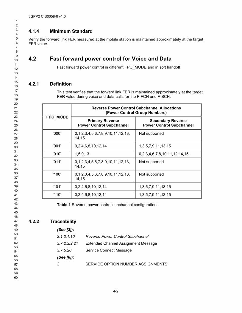
3GPP2 C.S0058-0 v1.0 1 2 3 4 5 6 7 8 9
10 11 12 13 14 15 16 17 18 19 20 21 22 23 24 25 26 27 28 29 30 31 32 33 34 35 36 37 38 39 40 41 42 43 44 45 46 47 48 49 50 51 52 53 54 55 56 57 58
4.1.4 Minimum Standard Verify the forward link FER measured at the mobile station is maintained approximately at the target FER value.
4.2 Fast forward power control for Voice and Data Fast forward power control in different FPC_MODE and in soft handoff
4.2.1 Definition This test verifies that the forward link FER is maintained approximately at the target FER value during voice and data calls for the F-FCH and F-SCH.
Reverse Power Control Subchannel Allocations (Power Control Group Numbers)
FPC_MODE Primary Reverse
Power Control Subchannel Secondary Reverse
Power Control Subchannel
‘000’ 0,1,2,3,4,5,6,7,8,9,10,11,12,13,14,15
Not supported
‘001’ 0,2,4,6,8,10,12,14 1,3,5,7,9,11,13,15
‘010’ 1,5,9,13 0,2,3,4,6,7,8,10,11,12,14,15
‘011’ 0,1,2,3,4,5,6,7,8,9,10,11,12,13,14,15
Not supported
‘100’ 0,1,2,3,4,5,6,7,8,9,10,11,12,13,14,15
Not supported
‘101’ 0,2,4,6,8,10,12,14 1,3,5,7,9,11,13,15
‘110’ 0,2,4,6,8,10,12,14 1,3,5,7,9,11,13,15
Table 1 Reverse power control subchannel configurations
4.2.2 Traceability (See [3]):
2.1.3.1.10 Reverse Power Control Subchannel
3.7.2.3.2.21 Extended Channel Assignment Message
3.7.5.20 Service Connect Message
(See [6]):
3 SERVICE OPTION NUMBER ASSIGNMENTS
59 60
4-2
3GPP2 C.S0058-0 v1.0 1 2 3 4 5 6 7 8 9 10 11 12 13 14 15 16 17 18 19 20 21 22 23 24 25 26 27 28 29 30 31 32 33 34 35 36 37 38 39 40 41 42 43 44 45 46 47 48 49 50 51 52 53 54 55 56 57 58
1.
2.
3.
4.
5.
6.
7.
8.
4.2.3 Method of Measurement Select a predetermined route where the mobile station would go through soft handoff pilot add/drop conditions and for which the mean receive power is approximately -75 dBm and the mean receive Pilot Ec/Io is larger than -12 dB.
Initiate a voice call using radio configuration RC3 and start driving along the selected route.
Monitor the forward link FER at the mobile station.
Verify that the forward link FER on the FCH is maintained approximately at the target FER value. Note that target FER can be verified by FPC_FCH_FER which is carried in Extended Channel Assignment Message, Power Control Message, Service Connect Message, General Handoff Direction Message and Universal Handoff Direction Message.
End the call at the mobile station.
Repeat steps 1 through 5 above using SO 33.
Verify that the F-FCH and F-SCH FER is maintained approximately at the target FER values. Note that target FER for F-FCH can be verified by FPC_FCH_FER which is carried in Extended Channel Assignment Message, Power Control Message, Service Connect Message, General Handoff Direction Message and Universal Handoff Direction Message, and target FER for F-SCH can be verified by FPC_SCH_FER which is carried in Power Control Message and Extended Supplemental Channel Assignment Message.
Repeat step 1 to 7 after selecting a route where the mobile station will get each FPC mode in Table 1 supported by the base station. Note that FPC_MODE can be verified by FPC_MODE and FPC_MODE_SCH fields. FPC_MODE field is carried in Power Control Message, Service Connect Message, General Handoff Direction Message, and Universal Handoff Direction Message. FPC_MODE_SCH field is carried in Extended Supplemental Channel Assignment Message.
4.2.4 Minimum Standard For all tests, the F-FCH and the F-SCH measured FER at the mobile station should be maintained approximately at the target FER value
59 60
4-3

3GPP2 C.S0058-0 v1.0 1 2 3 4 5 6 7 8 9
10 11 12 13 14 15 16 17 18 19 20 21 22 23 24 25 26 27 28 29 30 31 32 33 34 35 36 37 38 39 40 41 42 43 44 45 46 47 48 49 50 51 52 53 54 55 56 57 58
No text.
59 60
4-4
3GPP2 C.S0058-0 v1.0 1 2 3 4 5 6 7 8 9 10 11 12 13 14 15 16 17 18 19 20 21 22 23 24 25 26 27 28 29 30 31 32 33 34 35 36 37 38 39 40 41 42 43 44 45 46 47 48 49 50 51 52 53 54 55 56 57 58
5 Subscriber Calling Features Tests
5.1 Call Forwarding 5.1.1 Definition
These tests verify that Call Forwarding can be activated and deactivated from the mobile station. Call forwarding features tested in this test are Call Forwarding Unconditional (CFU), Call Forwarding Busy (CFB), Call Forwarding Default (CFD), and Call Forwarding No-Answer (CFNA). Call Forwarding features can be successfully activated or deactivated from the mobile station only if the network supports the call forwarding features.
5.1.1.1 Call Forwarding Unconditional (CFU)
CFU permits a called subscriber to send incoming calls addressed to the called subscriber’s Directory Number to another Directory Number (forward-to number) or to the called subscriber’s designated voice mailbox. If this feature is active, calls are forwarded regardless of the condition of the termination.
5.1.1.2 Call Forwarding Busy (CFB)
CFB permits a called subscriber to have the system send incoming calls to another Directory Number (forward-to number) or to the called subscriber’s designated voice mailbox, when the subscriber is engaged in a call or service.
5.1.1.3 Call Forwarding Default (CFD)
CFD permits a called subscriber to have the system send incoming calls to another Directory Number (forward-to number) or to the called subscriber’s designated voice mail box, when the subscriber is engaged in a call, does not answer the call within a specified period after being alerted or the mobile station is otherwise inaccessible.
5.1.1.4 Call Forwarding No Answer (CFNA)
CFNA permits a called subscriber to have the system send incoming calls addressed to the called subscriber’s Directory Number to another Directory Number (forward-to number) or to the called subscriber’s designated voice mailbox, when the subscriber fails to answer.
5.1.2 Traceability (See [3] ):
3.7.5.5 Signal
5.1.3 Method of Measurement
5.1.3.1 Call Forwarding, Unconditional 59 60
5-1
1. Power on the mobile station and wait until it goes into Mobile Station Idle State.
3GPP2 C.S0058-0 v1.0 1 2 3 4 5 6 7 8 9
10 11 12 13 14 15 16 17 18 19 20 21 22 23 24 25 26 27 28 29 30 31 32 33 34 35 36 37 38 39 40 41 42 43 44 45 46 47 48 49 50 51 52 53 54 55 56 57 58
2.
3.
4.
5.
6.
7.
8.
9.
10.
11.
12.
13.
1.
2.
3.
4.
5.
6.
7.
8.
9.
10.
11.
12.
13.
14.
15.
16.
17.
18.
Activate the Call Forwarding Unconditional (CFU) feature for the mobile station (e.g. dial the CFU feature activation code, followed by the forward-to number).
Verify feature update confirmation at the mobile station (could be a beep sound heard on the earpiece).
Attempt a call to the mobile station.
Verify the call is forwarded and if the network directs the mobile station to “Ping Ring” it does so (e.g. plays a single burst).
Answer the call on the forwarded line.
Verify the audio path.
End call.
Deactivate the CFU feature (e.g. dial the CFU deactivation feature).
Verify the feature update confirmation at the mobile station.
Set up a call to the mobile station.
Verify that the mobile station rings and call completes when answered.
If supported by the network, repeat the test except for at step 2, dial the CFU activation feature code, followed by voice mail number.
5.1.3.2 Call Forwarding, Busy
Power on the mobile station and wait until it goes into Mobile Station Idle State.
Activate the Call Forwarding Busy (CFB) feature for the mobile station (e.g. dial the CFB activation feature code, followed by the forward-to number). Ensure all other call forwarding features are disabled.
Verify feature update confirmation at the mobile station.
Place the mobile station in a voice call.
Attempt a call to the mobile station.
Verify the call is forwarded to the forward-to number or voice mail and if the network directs the mobile station to “Ping Ring” it does so (e.g. plays a single ring burst).
Answer the call on the forward line.
Verify the audio path.
End all calls.
Attempt a call to the mobile station while the mobile station is in idle state.
Verify that the call is not forwarded.
End the call.
Deactivate the CFB feature (e.g. dial the CFB deactivation feature code).
Verify feature update confirmation at the mobile station.
Set up a call to the mobile station.
Verify the call completes at the mobile station. Release the call.
59 60
5-2
Place the mobile station in a voice call.
Set up a call to the mobile station.
3GPP2 C.S0058-0 v1.0 1 2 3 4 5 6 7 8 9 10 11 12 13 14 15 16 17 18 19 20 21 22 23 24 25 26 27 28 29 30 31 32 33 34 35 36 37 38 39 40 41 42 43 44 45 46 47 48 49 50 51 52 53 54 55 56 57 58
19.
20.
1.
2.
3.
4.
5.
6.
7.
8.
9.
10.
11.
12.
13.
14.
15.
16.
17.
18.
19.
20.
1.
2.
3.
4.
5.
Verify the call is not forwarded.
If supported by the network repeat the test except that at step 2, dial the CFB activation feature code, followed by voice mail number.
5.1.3.3 Call Forwarding, Default
Power on the mobile station and wait until it goes into Mobile Station Idle State.
Activate the Call Forwarding Default (CFD) feature for the mobile station (e.g. dial the CFD activation feature code, followed by the forward-to number).
Verify feature update confirmation at the mobile station. Ensure that CFNA and CFB features for the mobile station are disabled.
Set up a call to the mobile station. Do not answer the call when mobile station is alerting.
Verify the call is forwarded and if the network directs the mobile station to “Ping Ring” it does so (e.g. plays a single ring burst).
Answer the call on the forward line.
Verify the audio path.
End call.
Place the mobile station in a voice call.
Attempt a call to the mobile station.
Verify the call is forwarded to the forward-to number or voice mail.
Answer the call on the forward line.
Verify the audio path.
Deactivate the CFD feature (e.g. dial the CFD deactivation feature code).
Verify feature update confirmation at the mobile station.
Set up a call to the mobile station.
Verify the call completes at the mobile station. Release the call.
Set up a call to the mobile station. Do not answer the call when mobile station is alerting.
Verify the call is not forwarded.
If supported by the network repeat the test except that at step 2, dial CFD activation feature code, followed by voice mail number.
5.1.3.4 Call Forwarding, No Answer
Power on the mobile station and wait until it goes into Mobile Station Idle State.
Activate the Call Forwarding No-Answer (CFNA) feature for the mobile station (e.g. dial the CFNA activation feature code, followed by the forward-to number). Ensure all other call forwarding features are disabled, and call waiting is enabled
Verify feature update confirmation at the mobile station.
Set up a call to the mobile station. Do not answer the call when mobile station is alerting.
59 60
5-3
Verify the call is forwarded to the forward-to number or voice mail and if the network directs the mobile station to “Ping Ring” it does so (e.g. plays a single ring burst).
3GPP2 C.S0058-0 v1.0 1 2 3 4 5 6 7 8 9
10 11 12 13 14 15 16 17 18 19 20 21 22 23 24 25 26 27 28 29 30 31 32 33 34 35 36 37 38 39 40 41 42 43 44 45 46 47 48 49 50 51 52 53 54 55 56 57 58
6.
7.
8.
9.
10.
11.
12.
13.
14.
15.
16.
17.
18.
19.
1.
2.
3.
4.
Answer the call on the forward line.
Verify the audio path.
End all calls.
Place the mobile station in a voice call.
Set up a call to the mobile station.
Verify that the user receives call waiting indication. Do not answer the call waiting call.
Verify the call is forwarded to the forward-to number or voice mail and if the network directs the mobile station to “Ping Ring” it does so (e.g. plays a single ring burst).
Deactivate the CFNA feature (e.g.dial the CFNA deactivation feature code).
Verify feature update confirmation at the mobile station.
Set up a call to the mobile station.
Verify the call completes at the mobile station. Release the call.
Set up a call to the mobile station. Do not answer the call when mobile station is alerting.
Verify the call is not forwarded.
If supported by the network repeat the test except that at step 2, dial CFNA activation feature code, followed by voice mail number.
5.1.4 Minimum Standard When call forwarding is activated, calls shall be forwarded to the forward-to number or voice-mail as programmed by the user.
When call forwarding is deactivated, the calls shall terminate at the mobile station normally.
5.2 Three-way calling 5.2.1 Definition
This test verifies that a mobile station authorized for Three-Way Calling can add a third party to an established two-way call.
5.2.2 Traceability (See [3]):
2.7.2.3.2.3 Flash with Information Message
2.7.2.3.2.33 Extended Flash With Information Message
5.2.3 Method of Measurement Set up a call from the mobile station to called party 1.
Verify audio in both directions.
59 60
5-4
Instruct the mobile station to put called party 1 on hold.
Verify the mobile station sends a Flash with Information Message/Extended Flash with Information Message to put called party 1 on hold, and called party 1 is put on hold.
3GPP2 C.S0058-0 v1.0 1 2 3 4 5 6 7 8 9 10 11 12 13 14 15 16 17 18 19 20 21 22 23 24 25 26 27 28 29 30 31 32 33 34 35 36 37 38 39 40 41 42 43 44 45 46 47 48 49 50 51 52 53 54 55 56 57 58
5.
6.
7.
8.
9.
10.
11.
12.
13.
14.
1.
2.
3.
4.
5.
6.
Using the mobile station, dial called party 2 number.
Verify that the mobile station sends a Flash with Information Message/Extended Flash with Information Message.
When the called party 2’s phone rings, answer the call from called party 2 (second leg of the three-way call).
Verify audio in both directions.
Instruct the mobile station to initiate the three-way connection.
Verify the mobile station sends a Flash with Information Message/Extended Flash with Information Message.
Verify the three-way connection is established.
If supported, instruct the mobile station to initiate the disconnection of the third-leg of the three-way call (e.g. press SEND key), otherwise go to step 14.
Verify that a Flash with Information Message/Extended Flash with Information Message is sent from the mobile station. Verify the three-way connection is disconnected and the call is returned to its original two-way state.
End call from the mobile station.
5.2.4 Minimum Standard Addition and dropping of the third party to a two way connection shall be successful. All calls shall be successful.
5.3 Call waiting 5.3.1 Definition
This test verifies that a mobile station in a two-way conversation with call waiting enabled, will receive notification of waiting calls. This test will verify that the mobile station will send a flash request to connect to the waiting call. Call Waiting Blocked feature is also checked.
5.3.2 Traceability (See [3]):
3.7.5.5 Signal
3.6.7.2 Requirements
5.3.3 Method of Measurement Ensure call waiting is enabled for the mobile station under test.
Make a mobile station to called party call.
Verify user data in both directions.
Set up a call from calling party to the mobile station. Wait for a ringback on calling party and the call waiting notification on the mobile station.
Press SEND on the mobile station. 59 60
5-5
Verify the mobile station sends a Flash With Information Message/Extended Flash with Information Message to the base station to switch over to calling party.
3GPP2 C.S0058-0 v1.0 1 2 3 4 5 6 7 8 9
10 11 12 13 14 15 16 17 18 19 20 21 22 23 24 25 26 27 28 29 30 31 32 33 34 35 36 37 38 39 40 41 42 43 44 45 46 47 48 49 50 51 52 53 54 55 56 57 58
7.
8.
9.
10.
11.
12.
13.
14.
15.
16.
17.
18.
19.
20.
21.
22.
23.
24.
25.
26.
Verify called party is on hold, and that a voice path is established between the mobile station and calling party.
Press SEND on the mobile station to put calling party on hold, and reconnect the voice path to called party.
Verify the mobile station sends a Flash With Information Message/Extended Flash with Information Message to the base station.
End called party call.
Press SEND on the mobile station.
Verify the mobile station sends a Flash With Information Message/Extended Flash with Information Message to the base station to switch over to calling party.
Verify user data between the mobile station and calling party.
End call.
Disable call waiting.
Set up a mobile station originated call to called party.
Verify user data in both directions.
Set up a call from calling party to the mobile station. Wait for the busy tone on calling party. Ensure that there is no call-waiting notification on the mobile station. End calls.
Enable call waiting.
If Call Waiting Blocked feature is available to the mobile station, repeat dialing the called party from the mobile station, but with a Call Waiting Blocked feature code before the dialed number (e.g. *70+number). Repeat steps 17 to 18.
Verify no Call Waiting Notification is observed on the mobile station, and the caller should be routed directly to Voice Mail or given a busy tone or a recording.
End all calls.
Establish a call from the mobile station without a Call Waiting Blocked feature code before the dialed number.
Set up a call from calling party to the mobile station.
Verify call waiting notification on the mobile station.
Release all calls.
5.3.4 Minimum Standard If call waiting is enabled the base station shall send a call waiting notification to the mobile station during a two-way conversation indicating another call is waiting. The mobile station shall send a flash request to connect with calling party, while called party is put on hold. With call waiting disabled, ensure the base station does not send a call waiting notification to the mobile station. If supported, the Call Waiting Blocked feature code shall prevent Call Waiting on a per-call basis.
59 60
5-6
3GPP2 C.S0058-0 v1.0 1 2 3 4 5 6 7 8 9 10 11 12 13 14 15 16 17 18 19 20 21 22 23 24 25 26 27 28 29 30 31 32 33 34 35 36 37 38 39 40 41 42 43 44 45 46 47 48 49 50 51 52 53 54 55 56 57 58
1.
2.
3.
4.
5.
6.
7.
8.
9.
10.
11.
12.
5.4 Caller ID 5.4.1 Definition
This test will verify Calling Number Identification Presentation (CNIP) provides the number identification of the calling party to the called subscriber.
5.4.2 Traceability (See [3]):
2.7.4: Information Records
3.7.2.3.2.12: Feature Notification Message
3.7.3.3.2.3: Alert with Information Message
3.7.3.3.2.14: Flash with Information Message
3.7.3.3.2.45: Extended Flash With Information Message
3.7.5: Information Records
5.4.3 Method of Measurement Ensure that Calling Number Identification Presentation (CNIP) is activated for the mobile station under test.
Set up a call to the mobile station from a phone that allows calling party number presentation.
Verify the mobile station receives and displays the Calling Party number.
End the call.
Set up a call to the mobile station from a phone that restricts calling party number presentation (e.g. by prefixing the dialed number with the mobile station Caller ID Blocked feature code).
Verify that the mobile station does not display the Calling Party Number.
End the call.
If the mobile station supports call waiting, repeat the steps 1 to 7 with following modification: The mobile station is in conversation state instead of idle state.
Ensure calling party number presentation is not restricted for the mobile station. Set up a call from the mobile station to a phone capable of displaying Caller ID.
Verify that the mobile station CPN is displayed on the called party phone.
Ensure calling party number presentation is not restricted for the mobile station. Set up a call from the mobile station to a phone capable of displaying Caller ID, but this time prefix the dialed number with the mobile station Caller ID Blocked feature code (e.g. *67).
Verify that the mobile station CPN is not displayed on the called party phone.
5.4.4 Minimum Standard
59 60
5-7
Verify that the mobile station displays Calling Party Number based on the Presentation Indicator when the mobile station receives a call. If the mobile station supports call waiting, verify that the mobile station displays Calling Party Number
3GPP2 C.S0058-0 v1.0 1 2 3 4 5 6 7 8 9
10 11 12 13 14 15 16 17 18 19 20 21 22 23 24 25 26 27 28 29 30 31 32 33 34 35 36 37 38 39 40 41 42 43 44 45 46 47 48 49 50 51 52 53 54 55 56 57 58
1.
2.
3.
4.
5.
6.
based on the Presentation Indicator when the mobile station receives a call when the mobile station is in conversation state. Note that Presentation Indicator can be verified by the PI field which are 00(Presentation Allowed), 01(Presentation Restricted) and 10(Number Not Available). This PI field is carried in the Alert With Information Message and Flash With Information Message.
The mobile station’s Caller ID CPN on outgoing calls shall be blocked when the dialed number is prefixed with the Caller ID Blocked feature code, if supported by the network.
5.5 Call Waiting Call Back 5.5.1 Definition
This test will verify Call Waiting Call Back. This feature forces the base station to call the mobile station in the following scenario:
• Mobile station is in conversation state with user 1.
• Mobile station receives a call from user 2 and switches to user 2 using call waiting.
• Mobile station terminates the call without switching back to user 1.
• Base station will automatically call the mobile station with user 1’s calling party number, if user 1 is still holding.
5.5.2 Traceability (See [3]):
3.7.5: Information Records
3.7.5.5 Signal
(See [7]):
5.7 Call Waiting
5.5.3 Method of Measurement Set up a mobile station originated call to user 1.
Verify user data in both directions.
Initiate a call from user 2 to the mobile station under test.
Answer the incoming call from the mobile station under test.
Once the mobile station is in conversation state with user 2, end the call from the mobile station (e.g. press the END key).
Verify that the base station calls the mobile station with user 1’s Calling Party Number.
5.5.4 Minimum Standard Verify that the Call Waiting Call Back feature works properly.
59 60
5-8
3GPP2 C.S0058-0 v1.0 1 2 3 4 5 6 7 8 9 10 11 12 13 14 15 16 17 18 19 20 21 22 23 24 25 26 27 28 29 30 31 32 33 34 35 36 37 38 39 40 41 42 43 44 45 46 47 48 49 50 51 52 53 54 55 56 57 58
1.
2.
3.
4.
5.
5.6 Voice Privacy 5.6.1 Definition
This test is for Voice Privacy as activated by the subscriber. The Voice Privacy feature allows the subscriber the ability to switch to the private long code mask that encodes the vocoder data. Check with the network operator to see if Voice Privacy is enabled.
5.6.2 Traceability (See [3]):
2.3.12.3: Voice Privacy
2.6.4.1.6: Long Code Transition Request Processing
2.7.1.3.2.4: Origination Message
2.7.1.3.2.5: Page Response Message
2.7.3: Orders
3.3.3: Voice Privacy
3.6.4.1.5: Long Code Transition Request Processing
3.6.4.3: Traffic Channel Substate
3.6.4.4: Release Substate
3.7.4: Orders
5.6.3 Method of Measurement If the network supports voice privacy, activate Voice Privacy on the mobile station.
Initiate a mobile station originated call.
Verify the mobile station indicates to the user that Voice Privacy is active on the call. Verify the Voice Privacy Mode Indicator is set to '1' in the Origination Message, the base station sends a Long Code Transition Request Order, and the mobile station responds with a Long Code Transition Response Order.
If the mobile station’s user interface supports activation of voice privacy, make another call, this time wait until after the call is in progress before activating Voice Privacy.
Verify the mobile station indicates to the user that Voice Privacy is now active on the call. Verify that the mobile station sends a Long Code Transition Request Order, the base station sends a Long Code Transition Request Order, and the mobile station responds with a Long Code Transition Response Order.
5.6.4 Minimum Standard Voice Privacy shall be correctly activated.
59 60
5-9
3GPP2 C.S0058-0 v1.0 1 2 3 4 5 6 7 8 9
10 11 12 13 14 15 16 17 18 19 20 21 22 23 24 25 26 27 28 29 30 31 32 33 34 35 36 37 38 39 40 41 42 43 44 45 46 47 48 49 50 51 52 53 54 55 56 57 58
1.
2.
3.
4.
5.
6.
7.
5.7 CDMA Authentication 5.7.1 Definition
This test is for CDMA Authentication using CDMA Layer 3 messages as the transport. The network operator should provide the location where authentication is used in the network. The network operator shall identify the scenarios that trigger authentication to be activated in the network. The scenarios could include registrations, originations, terminations, and base station initiated unique challenge procedures.
5.7.2 Traceability (See [3]):
2.3.12.1: Authentication
2.3.12.1.4: Unique Challenge-Response Procedure
2.3.12.1.5: Updating the Shared Secret Data (SSD)
2.6.5.1.3: Timer-Based Registration
2.7.1.3.2.6: Authentication Challenge Response Message
2.7.2.3.2.2: Authentication Challenge Response Message (r-dsch)
3.3.1: Authentication
3.7.2.3.2.1: System Parameters Message (f-csch)
3.7.3.3.2.2: Authentication Challenge Message (f-dsch)
3.7.2.3.2.10: Authentication Challenge Message (f-csch)
3.7.2.3.2.11: SSD Update Message (f-csch)
5.7.3 Method of measurement Verify that network authentication is activated by checking that AUTH field is set to ‘01’ in Access Parameters Message or SENDING_RAND field is set to ‘1’ in MC-RR Parameters Message.
Originate a voice call.
Verify that the mobile station includes AUTHR and RANDC fields in Origination Message and the call is successful.
Make a mobile station terminated voice call.
Verify that the mobile station includes AUTHR and RANDC fields in Page Response Message and the call is successful.
Cause the mobile station to send a Registration Message.
Verify that the mobile station includes AUTHR and RANDC fields in Registration Message and the registration is successful.
59 60
5-10
3GPP2 C.S0058-0 v1.0 1 2 3 4 5 6 7 8 9 10 11 12 13 14 15 16 17 18 19 20 21 22 23 24 25 26 27 28 29 30 31 32 33 34 35 36 37 38 39 40 41 42 43 44 45 46 47 48 49 50 51 52 53 54 55 56 57 58
1.
2.
3.
4.
5.
6.
7.
8.
9.
5.7.4 Minimum Standard The mobile station and base station shall perform normal authentication process without error.
5.8 Voice Mail Notification 5.8.1 Definition
This tests the Voice Mail Notification (VMN) feature. After a new voice mail message is left by a caller, the base station attempts to notify the mobile station. After the VMN is successfully delivered, a Voice Mail Message Waiting Indicator is displayed on the mobile station. This test also verifies that mobile station is able to display a missed call indication.
5.8.2 Traceability (See [4]):
4.3.5: Voice Mail Notification (VMN)
4.5.12 Number of Messages
(See [3]):
3.7.5.6: Message Waiting
3.7.2.3.2.12: Feature Notification Message
(See [7]):
1: Message Waiting Notification
5.8.3 Method of measurement Ensure there are no voice mail messages pending for the mobile station. With the mobile station powered off, leave 3 Voice Mail Messages for it.
Power on the mobile station. After some time the base station will send VMN.
Verify MSG_COUNT (or MESSAGE_CT) = 3 in the VMN sent by base station.
The mobile station may alert the user and may display a Voice Mail Message Waiting Indicator.
If the mobile station is capable of indicating the number of new voice mail messages, verify the mobile station indicates 3 new Voice Mail Messages.
While the mobile station is in the idle state, attempt a mobile station terminated call. Do not answer the call at the mobile station, and leave a voice mail message.
Wait for a VMN.
Verify VMN is successful and accurate. The mobile station may display an indication of a missed call.
59 60
5-11
Make a call with the mobile station. While the mobile station is in the conversation state, initiate a call to the mobile station, but do not answer the call. Leave a voice mail message.
3GPP2 C.S0058-0 v1.0 1 2 3 4 5 6 7 8 9
10 11 12 13 14 15 16 17 18 19 20 21 22 23 24 25 26 27 28 29 30 31 32 33 34 35 36 37 38 39 40 41 42 43 44 45 46 47 48 49 50 51 52 53 54 55 56 57 58
10.
11.
12.
1.
2.
3.
4.
5.
6.
7.
Keep the first call going, and wait for a VMN while in the conversation state. The VMN may be sent in a Flash with Information Message/Extended Flash with Information Message.
End the call.
Verify the VMN is successful and accurate. The mobile station may alert the user and may display a Voice Mail Message Waiting Indicator.
5.8.4 Minimum Standard The base station shall send accurate VMN. Note that the time at which VMN is sent is base station implementation dependent. When VMN is received, the mobile station may display the received VMN information. If the mobile station displays the VMN information, it shall be displayed correctly.
5.9 Voice Mail Retrieval 5.9.1 Definition
This test verifies a mobile station can retrieve voice mail messages. After all the voice mail messages stored for the mobile station are accessed, the base station sends a layer 3 message instructing the mobile station to turn off its Voice Mail Message Waiting Indicator.
5.9.2 Traceability (See [4]):
4.3.5: Voice Mail Notification (VMN)
4.5.12 Number of Messages
(See [3]):
3.7.5.6: Message Waiting
3.7.2.3.2.12: Feature Notification Message
5.9.3 Method of measurement Ensure there is no Voice Mail Notification in the mobile station.
Initiate a call to the mobile station. Do not answer the call and leave a voice mail message.
After receiving a new voice mail notification, attempt to retrieve the voice mail message by calling the mobile station voice mail access number from the mobile station.
After listening to the Voice Mail Message end the call.
Verify the base station sends VMN (e.g. Flash with Information Message or Data Burst Message), with MSG_COUNT (or MESSAGE_CT) = 0. Verify the mobile station voice mail message waiting indicator has been turned off after VMN is received (either before or after ending the call).
59 60
5-12
If the voice mail system supports a Call Back Number, activate it.
Verify the call completes to the correct number, if Call Back Number is activated.
3GPP2 C.S0058-0 v1.0 1 2 3 4 5 6 7 8 9 10 11 12 13 14 15 16 17 18 19 20 21 22 23 24 25 26 27 28 29 30 31 32 33 34 35 36 37 38 39 40 41 42 43 44 45 46 47 48 49 50 51 52 53 54 55 56 57 58
1.
2.
3.
5.9.4 Minimum Standard The mobile station shall successfully retrieve new voice mail messages. The voice mail message waiting indicator shall be turned off after the messages have been retrieved.
5.10 No Answer with Release Order 5.10.1 Definition
For an incoming call, while in the Waiting for Mobile Station Answer Substate, the mobile station may send a Release Order at the command of the subscriber, e.g. pressing the END button. This causes the base station to immediately release the traffic channel, and the caller to go directly to voice mail or a recording. In alternative implementation, the END button simply silences the mobile station ringer and makes the base station and caller wait for the maximum number of rings.
5.10.2 Traceability (See [3]):
2.7.3 Orders
5.10.3 Method of measurement Attempt a mobile station terminated call.
If supported, cause the mobile station to send a Release Order during the waiting for mobile station answer substate (e.g. press the END button).
Verify the mobile station sends a Release Order.
5.10.4 Minimum Standard The mobile station shall send a Release Order if commanded by the subscriber while in the Waiting for Mobile Station Answer Substate.
5.11 Mobile Station originated SMS 5.11.1 Definition
This test verifies that a short message can be sent by the mobile station on the common channel and on the traffic channel.
5.11.2 Traceability (See [4]):
2.4.1.1.1.2: Mobile SMS Message Origination
59 60
5-13
2.4.1.1.2.4: Mobile Station Message Origination in the Conversation Substate
2.4.2.1.1.1: Mobile SMS Message Origination
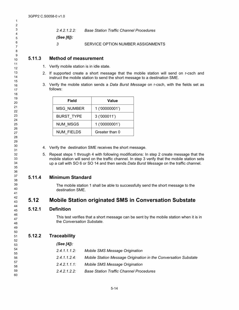
3GPP2 C.S0058-0 v1.0 1 2 3 4 5 6 7 8 9
10 11 12 13 14 15 16 17 18 19 20 21 22 23 24 25 26 27 28 29 30 31 32 33 34 35 36 37 38 39 40 41 42 43 44 45 46 47 48 49 50 51 52 53 54 55 56 57 58
1.
2.
3.
2.4.2.1.2.2: Base Station Traffic Channel Procedures
(See [6]):
3 SERVICE OPTION NUMBER ASSIGNMENTS
5.11.3 Method of measurement Verify mobile station is in idle state.
If supported create a short message that the mobile station will send on r-csch and instruct the mobile station to send the short message to a destination SME.
Verify the mobile station sends a Data Burst Message on r-csch, with the fields set as follows:
Field Value
MSG_NUMBER 1 (‘00000001’)
BURST_TYPE 3 (‘000011’)
NUM_MSGS 1 (‘00000001’)
NUM_FIELDS Greater than 0
4.
5.
Verify the destination SME receives the short message.
Repeat steps 1 through 4 with following modifications: In step 2 create message that the mobile station will send on the traffic channel. In step 3 verify that the mobile station sets up a call with SO 6 or SO 14 and then sends Data Burst Message on the traffic channel.
5.11.4 Minimum Standard The mobile station 1 shall be able to successfully send the short message to the destination SME.
5.12 Mobile Station originated SMS in Conversation Substate 5.12.1 Definition
This test verifies that a short message can be sent by the mobile station when it is in the Conversation Substate.
5.12.2 Traceability (See [4]):
2.4.1.1.1.2: Mobile SMS Message Origination
2.4.1.1.2.4: Mobile Station Message Origination in the Conversation Substate
2.4.2.1.1.1: Mobile SMS Message Origination 59 60
5-14
2.4.2.1.2.2: Base Station Traffic Channel Procedures
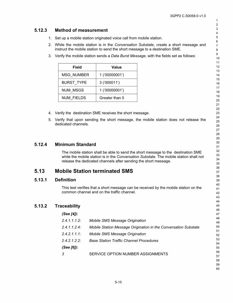
3GPP2 C.S0058-0 v1.0 1 2 3 4 5 6 7 8 9 10 11 12 13 14 15 16 17 18 19 20 21 22 23 24 25 26 27 28 29 30 31 32 33 34 35 36 37 38 39 40 41 42 43 44 45 46 47 48 49 50 51 52 53 54 55 56 57 58
1.
2.
3.
5.12.3 Method of measurement Set up a mobile station originated voice call from mobile station.
While the mobile station is in the Conversation Substate, create a short message and instruct the mobile station to send the short message to a destination SME.
Verify the mobile station sends a Data Burst Message, with the fields set as follows:
Field Value
MSG_NUMBER 1 (‘00000001’)
BURST_TYPE 3 (‘000011’)
NUM_MSGS 1 (‘00000001’)
NUM_FIELDS Greater than 0
4.
5.
Verify the destination SME receives the short message.
Verify that upon sending the short message, the mobile station does not release the dedicated channels.
5.12.4 Minimum Standard The mobile station shall be able to send the short message to the destination SME while the mobile station is in the Conversation Substate. The mobile station shall not release the dedicated channels after sending the short message.
5.13 Mobile Station terminated SMS 5.13.1 Definition
This test verifies that a short message can be received by the mobile station on the common channel and on the traffic channel.
5.13.2 Traceability (See [4]):
2.4.1.1.1.2: Mobile SMS Message Origination
2.4.1.1.2.4: Mobile Station Message Origination in the Conversation Substate
2.4.2.1.1.1: Mobile SMS Message Origination
2.4.2.1.2.2: Base Station Traffic Channel Procedures
(See [6]):
3 SERVICE OPTION NUMBER ASSIGNMENTS
59 60
5-15
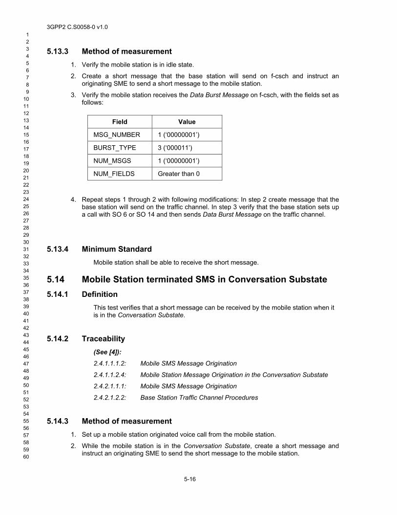
3GPP2 C.S0058-0 v1.0 1 2 3 4 5 6 7 8 9
10 11 12 13 14 15 16 17 18 19 20 21 22 23 24 25 26 27 28 29 30 31 32 33 34 35 36 37 38 39 40 41 42 43 44 45 46 47 48 49 50 51 52 53 54 55 56 57 58
1.
2.
3.
5.13.3 Method of measurement Verify the mobile station is in idle state.
Create a short message that the base station will send on f-csch and instruct an originating SME to send a short message to the mobile station.
Verify the mobile station receives the Data Burst Message on f-csch, with the fields set as follows:
Field Value
MSG_NUMBER 1 (‘00000001’)
BURST_TYPE 3 (‘000011’)
NUM_MSGS 1 (‘00000001’)
NUM_FIELDS Greater than 0
4.
1.
2.
Repeat steps 1 through 2 with following modifications: In step 2 create message that the base station will send on the traffic channel. In step 3 verify that the base station sets up a call with SO 6 or SO 14 and then sends Data Burst Message on the traffic channel.
5.13.4 Minimum Standard Mobile station shall be able to receive the short message.
5.14 Mobile Station terminated SMS in Conversation Substate 5.14.1 Definition
This test verifies that a short message can be received by the mobile station when it is in the Conversation Substate.
5.14.2 Traceability (See [4]):
2.4.1.1.1.2: Mobile SMS Message Origination
2.4.1.1.2.4: Mobile Station Message Origination in the Conversation Substate
2.4.2.1.1.1: Mobile SMS Message Origination
2.4.2.1.2.2: Base Station Traffic Channel Procedures
5.14.3 Method of measurement Set up a mobile station originated voice call from the mobile station.
59 60
5-16
While the mobile station is in the Conversation Substate, create a short message and instruct an originating SME to send the short message to the mobile station.
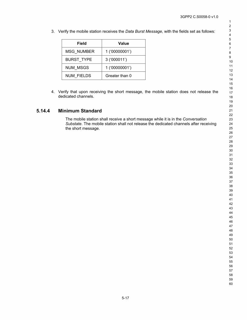
3GPP2 C.S0058-0 v1.0 1 2 3 4 5 6 7 8 9 10 11 12 13 14 15 16 17 18 19 20 21 22 23 24 25 26 27 28 29 30 31 32 33 34 35 36 37 38 39 40 41 42 43 44 45 46 47 48 49 50 51 52 53 54 55 56 57 58
3. Verify the mobile station receives the Data Burst Message, with the fields set as follows:
Field Value
MSG_NUMBER 1 (‘00000001’)
BURST_TYPE 3 (‘000011’)
NUM_MSGS 1 (‘00000001’)
NUM_FIELDS Greater than 0
4. Verify that upon receiving the short message, the mobile station does not release the dedicated channels.
5.14.4 Minimum Standard The mobile station shall receive a short message while it is in the Conversation Substate. The mobile station shall not release the dedicated channels after receiving the short message.
59 60
5-17

3GPP2 C.S0058-0 v1.0 1 2 3 4 5 6 7 8 9
10 11 12 13 14 15 16 17 18 19 20 21 22 23 24 25 26 27 28 29 30 31 32 33 34 35 36 37 38 39 40 41 42 43 44 45 46 47 48 49 50 51 52 53 54 55 56 57 58
No text.
59 60
5-18
3GPP2 C.S0058-0 v1.0 1 2 3 4 5 6 7 8 9 10 11 12 13 14 15 16 17 18 19 20 21 22 23 24 25 26 27 28 29 30 31 32 33 34 35 36 37 38 39 40 41 42 43 44 45 46 47 48 49 50 51 52 53 54 55 56 57 58
6 High-speed Packet Data For handoff test cases in this chapter the locations where handoff scenarios occur should be identified with help from network operator.
6.1 Forward file transfer 6.1.1 Definition
This test verifies that the mobile station can successfully complete a forward file transfer using the F-FCH and F-SCH, if supported, during a HSPD call.
6.1.2 Traceability (See [3]):
2.7.2.3.2.18: Supplemental Channel Request Message
2.7.2.3.2.28: Supplemental Channel Request Mini Message
3.6.6.2.2.12: Processing of Extended Supplemental Channel Assignment Message
3.7.3.3.2.24: Supplemental Channel Assignment Message
3.7.5.7.1: Channel Configuration for the Supplemental Channel
(See [5]):
2.2.3: Initialization and Connection of Packet Data Service Options
2.2.7: High Speed Operation
6.1.3 Method of measurement 1.
2.
3.
4.
5.
6.
Select a time to perform the test that is off peak hours. Select a location where the mobile station has one pilot in the active set and receive power averages approximately -75dBm.
Allow the mobile station to acquire a cdma2000 1x service.
At the remote host prepare an 800 kbyte binary file to be transferred using FTP to the data terminal connected to the mobile station. If the mobile station or the base station does not support Forward Supplemental Channel, use a 200 kbyte binary file.
Set up an FTP session using Service Option 33 with the remote host.
Transfer the file from the remote host to the mobile station using the binary “get” command.
After the file transfer is completed, end the FTP session. Record the elapsed time the file transfer took place.
6.1.4 Minimum Standard
59 60
6-1
The file shall be transferred successfully.
3GPP2 C.S0058-0 v1.0 1 2 3 4 5 6 7 8 9
10 11 12 13 14 15 16 17 18 19 20 21 22 23 24 25 26 27 28 29 30 31 32 33 34 35 36 37 38 39 40 41 42 43 44 45 46 47 48 49 50 51 52 53 54 55 56 57 58
1.
2.
3.
4.
5.
6.
6.2 Reverse file transfer 6.2.1 Definition
This test verifies that the mobile station can successfully complete a reverse file transfer using the R-FCH and R-SCH, if supported, during the HSPD call.
6.2.2 Traceability (See [3]):
2.7.2.3.2.18: Supplemental Channel Request Message
2.7.2.3.2.28: Supplemental Channel Request Mini Message
3.6.6.2.2.12: Processing of Extended Supplemental Channel Assignment Message
3.7.3.3.2.24: Supplemental Channel Assignment Message
3.7.5.7.1: Channel Configuration for the Supplemental Channel
(See [5]):
2.2.3: Initialization and Connection of Packet Data Service Options
2.2.7: High Speed Operation
6.2.3 Method of measurement Select a time to perform the test that is off peak hours. Select a location where the mobile station has one pilot in the active set and receive power averages approximately -75dBm.
Allow the mobile station to acquire a cdma2000 1x service.
Prepare an 800 kbyte binary file to be transferred using FTP from the data terminal connected to the mobile station. If the mobile station or the base station does not support Reverse Supplemental Channel, use a 200 kbyte binary file.
Set up an FTP session using Service Option 33 with the remote host.
Transfer the file from the mobile station to the remote host using the binary “put” command.
After the file transfer is completed, end the FTP session. Record the elapsed time the file transfer took place.
6.2.4 Minimum Standard The file shall be transferred successfully.
6.3 Bidirectional file transfer 6.3.1 Definition
59 60
6-2
This test verifies the mobile station can successfully complete a bi-directional file transfer during the HSPD call.
3GPP2 C.S0058-0 v1.0 1 2 3 4 5 6 7 8 9 10 11 12 13 14 15 16 17 18 19 20 21 22 23 24 25 26 27 28 29 30 31 32 33 34 35 36 37 38 39 40 41 42 43 44 45 46 47 48 49 50 51 52 53 54 55 56 57 58
1.
2.
3.
4.
5.
6.
6.3.2 Traceability (See [3]):
2.7.2.3.2.18: Supplemental Channel Request Message
2.7.2.3.2.28: Supplemental Channel Request Mini Message
3.6.6.2.2.12: Processing of Extended Supplemental Channel Assignment Message
3.7.3.3.2.24: Supplemental Channel Assignment Message
3.7.5.7.1: Channel Configuration for the Supplemental Channel
(See [5]):
2.2.3: Initialization and Connection of Packet Data Service Options
2.2.7: High Speed Operation
6.3.3 Method of measurement Select a time to perform the test that is off peak hours. Select a location where the mobile station has one pilot in the active set and receive power averages approximately -75dBm.
Allow the mobile station to acquire a cdma2000 1x system.
At the remote host and the data terminal connected to the mobile station, prepare an 800 kbyte binary file to be transferred using FTP to and from the mobile station. If the mobile station or the base station does not support Supplemental Channel, use a 200 kbyte binary file.
Set up an FTP session using Service Option 33 with the remote host.
Simultaneously start the transfer of the files from the mobile station to the remote host using the binary “put” command and the transfer of the file from the Remote Host to the mobile station using the binary “get” command.
After the file transfer is completed, end the FTP session. Record the elapsed time the file transfer took place.
6.3.4 Minimum Standard Both files shall be transferred successfully.
6.4 Soft handoff of fundamental channel and supplemental channels
6.4.1 Definition A CDMA call is established on one sector of base station 1. The mobile station will be moving to base station 2 such that soft handoff occurs for both F-FCH and F-SCH. This test is applicable only if the base station supports soft handoff for F-SCH.
59 60
6-3

3GPP2 C.S0058-0 v1.0 1 2 3 4 5 6 7 8 9
10 11 12 13 14 15 16 17 18 19 20 21 22 23 24 25 26 27 28 29 30 31 32 33 34 35 36 37 38 39 40 41 42 43 44 45 46 47 48 49 50 51 52 53 54 55 56 57 58
1.
2.
3.
4.
5.
6.
7.
8.
9.
10.
6.4.2 Traceability (See [3]):
2.6.6.2.7: Soft Handoff
3.6.6.2.4: Soft Handoff
2.7.4.25: Capability Information
2.7.4.27.3: FOR_SCH Type-Specific Field
3.7.5.7.1: Channel Configuration for the Supplemental Channel
(See [5]):
2.2.3: Initialization and Connection of Packet Data Service Options
2.2.7: High Speed Operation
6.4.3 Method of measurement Allow the mobile station to acquire a cdma2000 1x system. Ensure the mobile station is served by one sector of base station 1 only.
Place a HSPD data call from the mobile station and start forward file transfer. Ensure that the file size is such that the file transfer will continue until step 8.
Verify the base station sends the Extended Supplemental Channel Assignment Message to assign Supplemental Channels supported by the system. Verify only one pilot is in the active set.
Verify the file is being transferred from base station 1 to the mobile station.
Move (e.g. drive) to an area where the mobile station is in the boundary between the two base stations such that the second pilot level is higher than T_ADD.
Verify that the mobile station receives the data using the F-FCH and F-SCH of the two base stations (two pilots are in the active set for Fundamental Channel and Supplemental Channel).
Move (e.g. drive) away from the first base station toward the second base station until the mobile station has completely handed off to the second base station.
Verify only one pilot is in the active set for the Fundamental Channel and Supplemental Channel, and the mobile station receives the data using the forward Fundamental Channel and Supplemental Channel of the second base station.
Verify that the file transfer is successful.
End the call.
6.4.4 Minimum Standard Verify that the file transfer is successful.
6.5 Soft handoff of fundamental channel only 6.5.1 Definition
59 60
6-4
A CDMA call is established on a sector of base station 1. The mobile station will be moving to base station 2 such that soft handoff occurs for F-FCH. The mobile station
3GPP2 C.S0058-0 v1.0 1 2 3 4 5 6 7 8 9 10 11 12 13 14 15 16 17 18 19 20 21 22 23 24 25 26 27 28 29 30 31 32 33 34 35 36 37 38 39 40 41 42 43 44 45 46 47 48 49 50 51 52 53 54 55 56 57 58
1.
2.
3.
4.
5.
6.
7.
8.
9.
10.
and base station perform soft handoff of the fundamental channel. The Supplemental Channels remains active on either base station 1 or base station 2, but not both.
6.5.2 Traceability (See [3]):
2.6.6.2.7: Soft Handoff
3.6.6.2.4: Soft Handoff
2.7.4.25: Capability Information
2.7.4.27.3: FOR_SCH Type-Specific Field
3.7.5.7.1: Channel Configuration for the Supplemental Channel
(See [5]):
2.2.3: Initialization and Connection of Packet Data Service Options
2.2.7: High Speed Operation
6.5.3 Method of measurement Let the mobile station acquires cdma2000 1x system. Ensure the mobile station is served by one sector of base station 1 only.
Place a HSPD data call from the mobile station and start forward file transfer. Ensure that the file size is such that the file transfer will continue until step 8.
Verify that the first base station sends the Extended Supplemental Channel Assignment Message to assign Supplemental Channel. Verify only one pilot is in the active set.
Verify the file is being transferred from base station 1 to the mobile station.
Move (e.g. drive) to an area where the mobile station is in the boundary between two base stations such that the second pilot level is higher than T_ADD.
Verify that the mobile station shall receive the data using the F-FCH of base station 1 and base station 2 but the F-SCH of one base station (two pilots are in active set for Fundamental Channel and one pilot is in active set for Supplemental Channel).
Move (e.g. drive) away from base station 1 towards base station 2 until the mobile station has completely handed off to base station 2.
Verify that the mobile station receives the data using the forward Fundamental Channel and Supplemental Channel of the second base station.
Verify that the file transfer is successful.
End the call.
6.5.4 Minimum Standard Verify that the file transfer is successful.
59 60
6-5
3GPP2 C.S0058-0 v1.0 1 2 3 4 5 6 7 8 9
10 11 12 13 14 15 16 17 18 19 20 21 22 23 24 25 26 27 28 29 30 31 32 33 34 35 36 37 38 39 40 41 42 43 44 45 46 47 48 49 50 51 52 53 54 55 56 57 58
1.
2.
3.
4.
5.
6.
7.
8.
9.
6.6 Hard handoff to HSPD-capable system 6.6.1 Definition
A data-call hard handoff is performed to a different CDMA channel, and optionally to a different RC.
6.6.2 Traceability (See [3]):
2.6.6.2.7: Soft Handoff
3.6.6.2.4: Soft Handoff
2.7.4.25: Capability Information
2.7.4.27.3: FOR_SCH Type-Specific Field
3.7.5.7.1: Channel Configuration for the Supplemental Channel
(See [5]):
2.2.3: Initialization and Connection of Packet Data Service Options
2.2.7: High Speed Operation
6.6.3 Method of measurement Prepare a predetermined route where hard handoff can occur from base station 1 to base station 2.
Allow the mobile station to acquire a cdma2000 1x system.
At the remote host prepare a 1 Mbyte binary file to be transferred using FTP to the mobile station. If the mobile station or base station does not support F-SCH, use 200 kbytes file size.
o Base station 1 should be P_REV=6 or higher.
o Base station 2 should be P_REV=6 or higher operating on a different frequency channel from base station 1.
Set up a mobile station originated call with Service Option 33 on base station 1.
Begin forward file transfer from the remote host to the mobile station.
While the file is being transferred, move (e.g. drive) towards base station 2 until the mobile station is in the coverage area of base station 2.
Verify that hard handoff is successful and the file transfer continues after the hard handoff.
End FTP session.
If a route is available where base station 2 uses a different RC than the RC used by base station 1, then repeat steps 4 to 8 on this route.
59 60
6-6
3GPP2 C.S0058-0 v1.0 1 2 3 4 5 6 7 8 9 10 11 12 13 14 15 16 17 18 19 20 21 22 23 24 25 26 27 28 29 30 31 32 33 34 35 36 37 38 39 40 41 42 43 44 45 46 47 48 49 50 51 52 53 54 55 56 57 58
1.
2.
3.
4.
5.
6.
6.6.4 Minimum Standard The mobile station shall successfully handoff to an HSPD capable system of the same P_REV and different frequency channel or different RC. Data transfer shall be successful after the Hard Handoff.
6.7 HSPD PPP or IP Expiration 6.7.1 Definition
This test verifies that HSPD PPP connection maintenance is performed correctly in good coverage. This test also verifies expiration close of PPP connection during various timer expiration conditions. The PPP connection may be closed due to a PPP inactivity timer at the PDSN or a Mobile IP registration timer, or possibly some other timer. Note that in relay mode PPP inactivity timer may be configurable at TE2.
6.7.2 Traceability (See [11]):
4.7 Registration Lifetime Processing
7.7 Mobile IP Registration Expires
7.18 PDSN Terminates Simple IP Session Due to PDSN PPP Inactivity Timer Expiration
6.7.3 Method of measurement Identify from the network operator any network or mobile station timers for PPP inactivity or IP registration expiration.
Allow the mobile station to acquire cdma2000 1x service.
Make a HSPD connection to an internet site. Note down mobile station IP address.
Cease activity and allow the call to go to the PPP Dormant State.
If a timer is identified then continue with no activity for enough time for the first timer to expire. Ping the mobile station IP address.
Verify that the ping fails.
6.7.4 Minimum Standard Any network implemented PPP inactivity timer or IP registration expiration shall successfully close a PPP session.
59 60
6-7
3GPP2 C.S0058-0 v1.0 1 2 3 4 5 6 7 8 9
10 11 12 13 14 15 16 17 18 19 20 21 22 23 24 25 26 27 28 29 30 31 32 33 34 35 36 37 38 39 40 41 42 43 44 45 46 47 48 49 50 51 52 53 54 55 56 57 58
1.
2.
3.
4.
6.8 HSPD Mobile IP Inter-PDSN Active Handoff 6.8.1 Definition
This is a Mobile IP test for handoff from one PDSN to another, while a HSPD call is active.
6.8.2 Traceability (See [3]):
2.7.4.25: Capability Information
2.7.4.27.3: FOR_SCH Type-Specific Fields
3.7.5.7.1: Channel Configuration for the Supplemental Channel
(See [11]):
Inter-PDSN Handoff, Mobile Station in Active State
6.8.3 Method of measurement Select a drive route that will include a handoff from one PDSN to another.
Allow the mobile station to acquire cdma2000 1x service.
Starting on one side of the boundary, make a HSPD connection to an internet site.
Keep the SO33 call active i.e. do not allow the call to go dormant, while traveling across the PDSN boundary. This can be accomplished with file transfers, or by sending a repeated ping to a known IP address (e.g. ping www.XXXX – t).
6.8.4 Minimum Standard The call shall not drop. The internet connection shall be maintained with the same IP address at the mobile station.
6.9 HSPD Mobile IP Inter-PDSN Dormant Idle Handoff 6.9.1 Definition
This is a Mobile IP test to check mobile station dormant idle handoff to a different PDSN. For a SID or NID change a CDMA (HLR) registration on r-csch may accompany the MIP registration.
6.9.2 Traceability (See [3]):
2.6.2.1.2 Quick Paging Channel Monitoring Procedures.
2.6.5.1.6: Parameter-Change Registration
59 60
6-8
2.6.7.1 Hash Function
2.7.1.3.2.1 Registration Message
3GPP2 C.S0058-0 v1.0 1 2 3 4 5 6 7 8 9 10 11 12 13 14 15 16 17 18 19 20 21 22 23 24 25 26 27 28 29 30 31 32 33 34 35 36 37 38 39 40 41 42 43 44 45 46 47 48 49 50 51 52 53 54 55 56 57 58
1.
2.
3.
4.
5.
6.
1.
2.
3.6.5: Registration
3.7.2.3.2.1: System Parameters Message
3.7.2.3.2.13 Extended System Parameters Message
3.7.2.3.2.30 ANSI-41 System Parameters Message
(See [11]):
5.2 Inter-PDSN handoff, Mobile Station in Dormant State
6.9.3 Method of measurement Select a drive route which includes crossing a PDSN boundary.
Allow the mobile station to acquire a cdma2000 1x system.
Starting on one side of the boundary, make a HSPD connection to an internet site.
Cease activity and allow the call to go to the PPP Dormant State.
Travel across the PDSN boundary while in the PPP Dormant State.
Verify a new Packet Zone ID or SID or NID in the Extended System Parameters Message/ANSI-41 System Parameters Message. Verify that a SO33 call is originated for PPP negotiation and IP registration for a PDSN change.
6.9.4 Minimum Standard The dormant idle handoff shall be successful, maintaining the mobile IP address, and the connection to the internet site.
6.10 HSPD Ping while Dormant 6.10.1 Definition
The ability of the mobile station to respond to a ping of its IP address, while in the PPP Dormant State is verified.
6.10.2 Traceability (See [3]):
2.6.2.1.2 Quick Paging Channel Monitoring Procedures
2.6.3.3 Page Response Substate
2.7.1.3.2.5 Page Response Message
3.7.2.3.2.17 General Page Message
3.7.2.3.2.36 Universal Page Message
6.10.3 Method of measurement
59 60
6-9
Allow the mobile station to acquire cdma2000 1x service.
Make a HSPD connection to an internet site.
3GPP2 C.S0058-0 v1.0 1 2 3 4 5 6 7 8 9
10 11 12 13 14 15 16 17 18 19 20 21 22 23 24 25 26 27 28 29 30 31 32 33 34 35 36 37 38 39 40 41 42 43 44 45 46 47 48 49 50 51 52 53 54 55 56 57 58
3.
4.
5.
6.
1.
2.
3.
4.
5.
6.
7.
8.
9.
Record the IP address assigned to the mobile station.
Cease activity and allow the call to go to the PPP Dormant State.
Ping the mobile station IP address. Due to the latency of radio access, remember to employ the ping–w-timeout usage (e.g. set to 10000 milliseconds or more).
Verify that the ping is successful. A valid response to the ping command should occur approximately within the slot cycle (e.g. 5 seconds for slot cycle index 2) if the mobile station is in good coverage.
6.10.4 Minimum Standard The ping shall be successful.
6.11 HSPD Call Drop or Temporary Loss of Service 6.11.1 Definition
This is a test for mobile station behavior when a HSPD call is dropped or temporarily stays out of coverage in the PPP Dormant State.
6.11.2 Traceability (See [3]):
2.6.2.1.1.4 Common Channel Supervision
2.6.4.1.8 Forward Traffic Channel Supervision
6.11.3 Method of measurement Allow the mobile station to acquire cdma2000 1x service.
Make a HSPD connection to an internet site.
Move (e.g. drive) out of CDMA coverage area or shield the mobile station from the CDMA signal (e.g. put in a shield box).
If the mobile station was in the PPP Active State, the call will drop.
If the mobile station was in the Dormant State prior to losing service, it should show loss of service or roaming indication.
Verify that the mobile station PPP session is still connected, and the mobile station has retained its IP address.
Return to good CDMA coverage within a few minutes (prior to expiration of PPP inactivity timer or Mobile IP registration timer).
Ping the mobile station IP address.
Verify that the ping is successful.
59 60
6-10

3GPP2 C.S0058-0 v1.0 1 2 3 4 5 6 7 8 9 10 11 12 13 14 15 16 17 18 19 20 21 22 23 24 25 26 27 28 29 30 31 32 33 34 35 36 37 38 39 40 41 42 43 44 45 46 47 48 49 50 51 52 53 54 55 56 57 58
1.
2.
3.
4.
5.
6.
7.
8.
9.
10.
11.
12.
6.11.4 Minimum Standard The mobile station or application may indicate that the call was dropped or service was lost, but it shall recover successfully after returning to CDMA coverage. PPP shall be maintained at the mobile station, and ping should be successful after returning to good CDMA coverage.
6.12 HSPD and SMS 6.12.1 Definition
This test checks interaction of SMS and HSPD calls.
6.12.2 Traceability (See [4]):
2.4.1.1.2.2 Mobile SMS Message Termination
2.4.2.1.2 Base Station Traffic Channel Procedures
2.4.2.1.2.4 Mobile Station Message Termination in the Conversation Substate
6.12.3 Method of measurement Allow the mobile station to acquire cdma2000 1x service.
Make a HSPD connection to an internet site.
Ensure the call stays in the active state. This can be accomplished with file transfers, or by sending a continuous ping to a known IP address, e.g. ping www.XXXX – t.
If a mobile station can support SMS origination while in HSPD active state, send a mobile station originated SMS message.
Verify that a mobile station originated SMS message can be sent successfully while in a HSPD active state.
Send a mobile station terminated SMS message.
Verify that the mobile station terminated SMS message can be received successfully while in a HSPD active state.
Cease activity and allow the HSPD call to go to the HSPD Dormant State.
Send mobile station originated SMS message.
Verify that a mobile station originated SMS message can be sent successfully while in a HSPD dormant state.
Send a mobile station terminated SMS message.
Verify that the mobile station terminated SMS message can be received successfully while in a HSPD dormant state.
59 60
6-11

3GPP2 C.S0058-0 v1.0 1 2 3 4 5 6 7 8 9
10 11 12 13 14 15 16 17 18 19 20 21 22 23 24 25 26 27 28 29 30 31 32 33 34 35 36 37 38 39 40 41 42 43 44 45 46 47 48 49 50 51 52 53 54 55 56 57 58
6.12.4 Minimum Standard SMS and HSPD (both active and dormant states) shall operate concurrently without error.
59 60
6-12
3GPP2 C.S0058-0 v1.0 1 2 3 4 5 6 7 8 9 10 11 12 13 14 15 16 17 18 19 20 21 22 23 24 25 26 27 28 29 30 31 32 33 34 35 36 37 38 39 40 41 42 43 44 45 46 47 48 49 50 51 52 53 54 55 56 57 58
7 Packet Data Services Tests
7.1 File Transfer This test is required for mobile station operation in P_REV_IN_USE <= 3.
7.1.1 Definition This test demonstrates the ability of the mobile station to transfer files to and from a remote host.
7.1.2 Traceability (See [5]):
4.1 RFC-959
7.1.3 Method of measurement 1.
2.
3.
4.
5.
6.
7.
Select a time to perform the test that is off peak hours. Select a location where the mobile station is in single sector coverage and in a close proximity to the sector’s antenna.
Allow the mobile station to acquire a CDMA system with P_REV less than or equal to 3.
At the remote host prepare a 200 kbytes binary file to be transferred using FTP from/to the mobile station.
Initiate an FTP session with the remote host.
Transfer a file from the mobile station to a remote host using the binary “put” command and record transfer time.
Transfer a file from the remote host to the mobile station using the binary “get” command and record transfer time.
End the call.
7.1.4 Minimum Standard The file shall be transferred successfully.
7.2 Simple IP Establishment 7.2.1 Definition
This test verifies the proper operation of Simple IP. This test verifies the mobile station can terminate the PPP session.
59 60
7-1
3GPP2 C.S0058-0 v1.0 1 2 3 4 5 6 7 8 9
10 11 12 13 14 15 16 17 18 19 20 21 22 23 24 25 26 27 28 29 30 31 32 33 34 35 36 37 38 39 40 41 42 43 44 45 46 47 48 49 50 51 52 53 54 55 56 57 58
1.
2.
3.
4.
5.
1.
2.
3.
4.
7.2.2 Traceability (See [11]):
3.1 Simple IP Establishment without Authentication of the Mobile Station
3.2 Simple IP Establishment with CHAP
3.3 Simple IP Establishment with PAP
7.2.3 Method of measurement Ensure that the mobile station is in good coverage area where receive power is approximately -75 dBm.
Set up a mobile station originated Service Option 33 call.
Verify that a session is established with any of the following options based on infrastructure support: no authentication, CHAP or PAP.
Terminate the session.
Verify the mobile station is in the Null State.
7.2.4 Minimum Standard The mobile station shall be able to establish and terminate a Simple IP session successfully.
7.3 Registration Lifetime Processing 7.3.1 Definition
This test verifies the mobile station accepts a Mobile IP Registration Reply with the registration lifetime less than the requested lifetime. The network operator should provide a location where MobileIP is used in the network.
7.3.2 Traceability (See [11]):
4.7 Registration Lifetime Processing
7.3.3 Method of measurement Set up a mobile station originated Service Option 33 call.
Verify the PDSN/FA sends an Agent Advertisement to the mobile station after the PPP session is established.
Verify the mobile station sends a valid Mobile IP RRQ with the Lifetime less than or equal to the value in the Agent Advertisement.
59 60
7-2
Verify the PDSN/FA sends the Mobile IP RRP to the mobile station with the Code field set to 0 (Registration Accepted). The PDSN/FA will update the binding information for the mobile station.
3GPP2 C.S0058-0 v1.0 1 2 3 4 5 6 7 8 9 10 11 12 13 14 15 16 17 18 19 20 21 22 23 24 25 26 27 28 29 30 31 32 33 34 35 36 37 38 39 40 41 42 43 44 45 46 47 48 49 50 51 52 53 54 55 56 57 58
5.
6.
Verify the mobile station attempts to re-register before the Registration Lifetime value received in the Mobile IP RRP, decreased by the RRP lifetime difference, expires.
Verify the mobile station Mobile IP RRQ uses a valid and unused challenge value.
7.3.4 Minimum Standard The mobile station shall attempt to re-register before the Registration Lifetime in the Mobile IP RRP expires.
59 60
7-3

3GPP2 C.S0058-0 v1.0 1 2 3 4 5 6 7 8 9
10 11 12 13 14 15 16 17 18 19 20 21 22 23 24 25 26 27 28 29 30 31 32 33 34 35 36 37 38 39 40 41 42 43 44 45 46 47 48 49 50 51 52 53 54 55 56 57 58
No text.
59 60
7-4

3GPP2 C.S0058-0 v1.0 1 2 3 4 5 6 7 8 9 10 11 12 13 14 15 16 17 18 19 20 21 22 23 24 25 26 27 28 29 30 31 32 33 34 35 36 37 38 39 40 41 42 43 44 45 46 47 48 49 50 51 52 53 54 55 56 57 58
8 Position Determination Tests The position determination test cases in this chapter are applicable only if position determination can be initiated by some operation on the mobile station, the network supports delivering location information to the mobile station when mobile station can not calculate the location on its own, and mobile station is able to indicate location to the user. The network operator should identify locations where position determination tests are to be executed.
8.1 Position Determination 8.1.1 Definition
This test verifies the position determination feature.
8.1.2 Traceability (See [9]):
3.2.1 Position Determination Data Message Processing
3.2.2 Point-to-point Procedures
3.2.4 Reverse Link Message Format
3.2.4.2 Response Element Response Type
Annex B Request/Response Element Types
8.1.3 Method of measurement 1.
2.
a.
b.
Power on the mobile station and wait until it goes into Mobile Station Idle State.
For each test location identified by the network operator, perform the following:
Initiate an operation on the mobile station that results in the mobile station performing position determination.
Verify that the mobile station indicates the location. Record the location.
8.1.4 Minimum Standard The mobile station shall display the locations within tolerance limits acceptable to the network operator.
59 60
8-1

3GPP2 C.S0058-0 v1.0 1 2 3 4 5 6 7 8 9
10 11 12 13 14 15 16 17 18 19 20 21 22 23 24 25 26 27 28 29 30 31 32 33 34 35 36 37 38 39 40 41 42 43 44 45 46 47 48 49 50 51 52 53 54 55 56 57 58
No text.
59 60
8-2
3GPP2 C.S0058-0 v1.0 1 2 3 4 5 6 7 8 9 10 11 12 13 14 15 16 17 18 19 20 21 22 23 24 25 26 27 28 29 30 31 32 33 34 35 36 37 38 39 40 41 42 43 44 45 46 47 48 49 50 51 52 53 54 55 56 57 58
9 HRPD Tests
9.1 HRPD Acquisition and Idle Mode Operation 9.1.1 Definition
These tests will verify that the AT acquires the HRPD system and performs idle monitoring of the HRPD control channel. These tests also verify that upon losing the HRPD system during idle operation, the AT tries to reacquire the HRPD system.
9.1.2 Traceability (See [8]):
6.4.6.1.5 Monitor State
9.1.3 Method of measurement 1.
2.
3.
4.
5.
Power up the AT and place it where receive power is approximately -75 dBm.
Verify that the AT acquires HRPD system
Verify that after acquiring HRPD system, the AT performs idle monitoring of the control channel on the HRPD system
Cause the AT to lose the HRPD system (e.g. move outside the HRPD coverage).
Verify that the AT re-acquires the HRPD system when HRPD coverage is available again (e.g. when the AT is moved back to the HRPD coverage area).
9.1.4 Minimum Standard The AT shall successfully acquire the HRPD system upon power up. It shall monitor the control channel and stay in idle state. Upon losing the HRPD system, the AT shall try and successfully reacquire the system when HRPD coverage is available again.
9.2 AT initiated HRPD Session Configuration 9.2.1 Definition
This test verifies the proper implementation of initial session configuration.
9.2.2 Traceability (See [8]):
5.2 Default Session Management Protocol
59 60
9-1
9.2.3 Method of measurement 1. Power up the AT and place it where receive power is approximately -75 dBm.
3GPP2 C.S0058-0 v1.0 1 2 3 4 5 6 7 8 9
10 11 12 13 14 15 16 17 18 19 20 21 22 23 24 25 26 27 28 29 30 31 32 33 34 35 36 37 38 39 40 41 42 43 44 45 46 47 48 49 50 51 52 53 54 55 56 57 58
2. Verify that the AT acquires the HRPD system and goes to the idle state. Verify that the AT requests a UATI and the AN assigns it, as specified in the “address management” test case described in this section.
3. Verify that after UATI assignment, the AT opens a new HRPD connection and starts session negotiation using sets of ConfigRequest/ConfigResponse messages.
9.2.4 Minimum Standard The AT and the AN shall be able to successfully negotiate all initial session configuration parameters configured by each protocol in [8].
9.3 HRPD Session Configuration and Management with Subnet change
9.3.1 Definition This test verifies session configuration and management associated with a subnet change. If the AT moves to a new subnet and if the new subnet can retrieve the AT’s prior session configuration from the old subnet, new session negotiations are not needed. If the “Prior session attribute is supported by the AN, it can use the previously negotiated set of session parameters. For this test the location where the subnet change occurs should be identified with help from the network operator.
9.3.2 Traceability (See [8]):
5.3 Default Address Management Protocol
9.3.3 Method of measurement 1. Power up the AT and place it where receive power is approximately -75 dBm.
2. Verify that the AT acquires the HRPD system and goes to the idle state. Verify that the AT requests a UATI and the AN assigns it, as specified in the “address management” test case described in this section.
3. Verify that after UATI assignment, the AT opens a new HRPD connection and starts session negotiation using sets of ConfigRequest/ConfigResponse messages.
4. After a HRPD session is opened successfully, move the AT to another subnet where the prior session attribute is accepted.
5. Verify that in this subnet, the AT sends a ConfigRequest with the current session token and the AN sends back a ConfigResponse. Verify that the AT does not go through a new set of session negotiations after receiving the ConfigResponse form the AN.
9.3.4 Minimum Standard If supported, the AN shall be able to restore a prior session whenever the AT moves to a new subnet area.
59 60
9-2
3GPP2 C.S0058-0 v1.0 1 2 3 4 5 6 7 8 9 10 11 12 13 14 15 16 17 18 19 20 21 22 23 24 25 26 27 28 29 30 31 32 33 34 35 36 37 38 39 40 41 42 43 44 45 46 47 48 49 50 51 52 53 54 55 56 57 58
a.
b.
9.4 HRPD keep alive mechanism 9.4.1 Definition
This test verifies the proper functionality of the keep alive mechanism. The AT and the AN keep track of session status with the help of a “keep alive timer”. After an inactivity period defined by this timer, a KeepAliveRequest may be issued and a response within a certain time period is expected.
9.4.2 Traceability (See [8]):
5.2.6.1.6.1 Keep Alive Functions
9.4.3 Method of measurement 1. Power up the AT and place it where receive power is approximately -75 dBm.
2. Verify that the AT acquires the HRPD system and goes to the idle state. Verify that the AT requests a UATI and the AN assigns it, as specified in the “address management” test case described in this section.
3. Verify that after UATI assignment, the AT opens a new HRPD connection and starts session negotiation using sets of ConfigRequest/ConfigResponse messages.
4. Terminate all data activities to and from the AT for a period greater than TSMPClose
5. Verify the following if an inactivity period of (TSMPClose/NSMPKeepAlive) minutes at either the AT or the AN expires and a KeepAliveRequest is issued:
Verify that the recipient of the KeepAliveRequest message responds with a KeepAliveResponse message.
Verify that upon receipt of the KeepAliveResponse message, the recipient does not send another KeepAliveRequest message for at least another (TSMPClose/NSMPKeepAlive) minutes.
6. Verify that if the AT does not receive any response from the AN for a period of TSMPClose minutes, it terminates the session.
7. Verify that if TSMPClose is set to zero, the keep alive mechanism between the AT and the AN is disabled.
9.4.4 Minimum Standard Both the AT and the AN shall be able to correctly manage the KeepAlive mechanism.
9.5 Preferred Control Channel Cycle (PCCC) Negotiation 9.5.1 Definition
59 60
9-3
This test will verify that the AT and the AN successfully perform PCCC negotiation. The AT proposes PCCC attribute during the AT initiated phase of the session negotiation.
3GPP2 C.S0058-0 v1.0 1 2 3 4 5 6 7 8 9
10 11 12 13 14 15 16 17 18 19 20 21 22 23 24 25 26 27 28 29 30 31 32 33 34 35 36 37 38 39 40 41 42 43 44 45 46 47 48 49 50 51 52 53 54 55 56 57 58
1.
2.
3.
4.
5.
a.
b.
9.5.2 Traceability (See [8]):
6.4.6.1.4 Sleep State
9.5.3 Method of measurement Ensure that the AT has a closed HRPD session.
Power up the AT and place it where receive power is approximately -75 dBm for HRPD system.
Verify that the AT acquires the HRPD system and goes to idle state on the HRPD system.
Verify that the AT successfully negotiates the Preferred Control Channel cycle and starts the slotted mode idle operation.
Verify the AT can receive Page Message on the HRPD system while in dormant state.
9.5.4 Minimum Standard An AT shall be able to successfully determine and negotiate a suitable PCCC in the HRPD control channel.
9.6 Address Management 9.6.1 Definition
This test verifies the proper implementation of the address management protocol. Whenever the AT opens a new HRPD session, the AN assigns an initial UATI to the AT. The AN uses this UATI to uniquely identify an AT. As the AT moves around in the network, a new UATI is assigned every time it crosses a subnet boundary and moves into a new subnet area. For this test the location where a subnet change occurs should be identified with help from network operator.
9.6.2 Traceability (See [8]):
5.3.7.1.6 Open State
9.6.3 Method of measurement 1. Ensure that the AT has a closed HRPD session.
2. Power up the AT and place it where receive power is approximately -75 dBm.
3. Verify that the AT acquires HRPD system and goes to the idle state.
4. Verify that the following messages are exchanged to open a new HRPD session:
The AT sends a UATIRequest Message with a RATI 59 60
9-4
If the AN sends a HardwareIDRequest Message, then the AT sends a HardwareIDResponse Message
3GPP2 C.S0058-0 v1.0 1 2 3 4 5 6 7 8 9 10 11 12 13 14 15 16 17 18 19 20 21 22 23 24 25 26 27 28 29 30 31 32 33 34 35 36 37 38 39 40 41 42 43 44 45 46 47 48 49 50 51 52 53 54 55 56 57 58
c.
d.
a.
b.
c.
The AN sends a UATIAssignment Message
The AT sends a UATIComplete Message
5. Move (e.g. drive) around various subnet boundaries.
6. Verify that the AT updates the UATI in new subnets.
7. Set up a HRPD data call in every subnet area.
8. Verify that HRPD session and data connectivity are properly maintained.
9.6.4 Minimum Standard The AT shall be able to request and receive a new UATI upon new session opening. The AT shall be able to update its UATI when moving across the subnet boundaries. The AT shall be able to appropriately respond upon receiving a HardwareIDRequest message.
9.7 Access Authentication (AN Authentication) 9.7.1 Definition
This test verifies that the AT and the AN can successfully perform access authentication via PPP CHAP protocol as outlined in [10]. The AT will enable flow on the stream to which the Default Packet application bound to the access network is mapped. Depending upon the AN implementation, AN will either initiate the authentication processes immediately after a successful session negotiation or just before a data call setup. AN authentication is checked for either case of initial session negotiation or initial data call setup.
9.7.2 Traceability (See [8]):
2.3.1 PPP Session
9.7.3 Method of measurement 1. Verify that the CHAP authentication is enabled on the AN side.
2. Verify that the correct username and password are provisioned in the AT for CHAP authentication.
3. Ensure that the AT has a closed HRPD session.
4. Place AT where it can receive a good HRPD signal with receive power of approximately -75 dBm, and allow the AT to negotiate a session.
5. Verify that the AT successfully completes the session negotiation.
6. If the AN performs authentication immediately after the session negotiation:
Verify that the AN sends the CHAP Challenge message and initiates the AN authentication.
59 60
9-5
Set up a data call on HRPD system.
Verify that data can be transferred in both directions.
3GPP2 C.S0058-0 v1.0 1 2 3 4 5 6 7 8 9
10 11 12 13 14 15 16 17 18 19 20 21 22 23 24 25 26 27 28 29 30 31 32 33 34 35 36 37 38 39 40 41 42 43 44 45 46 47 48 49 50 51 52 53 54 55 56 57 58
a.
b.
c.
a.
1.
2.
3.
4.
a.
b.
5.
6.
7.
7. If the AN performs authentication just before the data call setup:
Set up a data call on the HRPD system.
Verify that the AN sends the CHAP Challenge message and initiates the AN authentication.
Verify that after completion of the AN authentication, the data call is successfully set up and data can be transferred in both directions.
8. Provision an incorrect username and password in the AT and repeat steps 3 through 7 of this procedure with modification to verify steps as follows:
Verify that the AN authentication fails. The AN may close the HRPD session. Ignore verification steps related to successful data call setup and data transfer.
9.7.4 Minimum Standard The AT shall pass the AN authentication if it is configured with a correct username and password. The AT shall fail the AN authentication if it is configured with an incorrect username and password.
9.8 DH Key Exchange and SHA-1 Authentication 9.8.1 Definition
This test verifies that AN-AT correctly negotiate the default keys for DH key exchange protocol and SHA-1 authentication protocol. For this test the location where DH key exchange occurs should be identified with help from network operator.
9.8.2 Traceability (See [8]):
7.5 Default Key Exchange Protocol
9.8.3 Method of measurement Power up the AT and place it where receive power is approximately -75 dBm.
Verify that the AT acquires the HRPD system and goes to idle mode.
Verify that the AT starts the session negotiation to open a new session.
Verify during the session configuration that: The AT responds to the KeyRequest message with KeyResponse message within TKEPATResponse (3 seconds)
The AT responds to the ANKeyComplete message with ATKeyComplete message within TKEPSigCompAT (3 seconds)
Verify that the AT is able to open a session successfully.
Originate a packet data call.
59 60
9-6
Verify that the data call can be successfully established and the data can be transferred in both directions.
3GPP2 C.S0058-0 v1.0 1 2 3 4 5 6 7 8 9 10 11 12 13 14 15 16 17 18 19 20 21 22 23 24 25 26 27 28 29 30 31 32 33 34 35 36 37 38 39 40 41 42 43 44 45 46 47 48 49 50 51 52 53 54 55 56 57 58
1.
2.
3.
4.
5.
6.
7.
9.8.4 Minimum Standard The AT shall be able to successfully negotiate the default keys for DH key exchange protocol and SHA-1 authentication protocol.
9.9 HRPD Control Channel Monitoring and Overhead Message Updates
9.9.1 Definition This test will verify that the AT can successfully receive and update QuickConfig and SectorParameters messages that are transmitted over the Control Channel. The AN transmits a QuickConfig message in every synchronous Control Channel cycle. The SectorParameters message is transmitted at least once every NOMPSectorParameters Control Channel cycles. In Idle State, the AT performs timer based supervision of the QuickConfig and SectorParameters messages. If the AT does not receive these messages within the expiry time of the corresponding timers, it returns a supervision failure indication.
9.9.2 Traceability (See [8]):
6.8.6.1.6.1 Supervision Procedures
9.9.3 Method of measurement Power up the AT and place it where receive power is approximately -75 dBm.
Configure the AT to operate in non-slotted (sleep disabled) mode. Note that tools and procedures to configure the AT in non-slotted mode are vendor dependent.
Monitor the periodicity of Sync message, Quickconfig message, SectorParameter message, and AccessParameter message.
Check the AN configuration for periodicity of these messages.
Verify that received messages have same periodicity as configured at the AN.
Configure the AT to operate in slotted (sleep enabled) mode. Note that tools and procedures to configure the AT in slotted mode are vendor dependent.
Verify that the AT receives and updates the overhead messages (QuickConfig and SectorParameter messages) and performs the supervision of these messages by resetting the TOMPQCSupervision and TOMPSPSupervision timers.
9.9.4 Minimum Standard The AT shall successfully monitor and update control channel overhead messages with any periodicity for corresponding messages, defined in [8]. Verify if QuickConfig and SectorParameter messages are not received within TOMPQCSupervision and TOMPSPSupervision respectively, the AT performs the supervision procedures and goes to initialization state.
59 60
9-7
3GPP2 C.S0058-0 v1.0 1 2 3 4 5 6 7 8 9
10 11 12 13 14 15 16 17 18 19 20 21 22 23 24 25 26 27 28 29 30 31 32 33 34 35 36 37 38 39 40 41 42 43 44 45 46 47 48 49 50 51 52 53 54 55 56 57 58
1.
2.
3.
4.
5.
6.
7.
8.
9.
10.
11.
9.10 HRPD Location Update Protocol tests 9.10.1 Definition
This test verifies the proper functionality of Location update feature.
9.10.2 Traceability (See [8]):
3.5.4.1 Procedures
9.10.3 Method of measurement Verify during Session negotiation, that the AN sets the RANHandoff attribute of the default Packet application to 0x01.
Power up the AT and place it where receive power is approximately -75 dBm.
Verify that the AT successfully completes the session negotiation.
Depending on the implementation the AN can send Location Assignment message to the AT.
Verify that upon receiving Location Assignment message, the AT sends a Location complete message and stores the Location Values in the Location Assignment message as the current Location Values.
Depending on the implementation the AN can send Location Request message.
Verify that upon receipt of this message, the AT responds with Location Notification message, which shall contain the current Location values of the AT.
Originate a packet data call.
Verify that the data call can be successfully established and the data can be transferred.
Let the AT go dormant. Move the AT to an area where there is no HRPD signal. The AT will lose the HRPD signal and go to acquisition state. Move the AT to an area where there is a HRPD signal belonging to a different subnet.
Verify that the AT acquires the system, negotiates session with the HRPD system, and sends an unsolicited Location Notification Message after the session is negotiated.
9.10.4 Minimum Standard The AT shall be able to successfully report its current location values to the AN. The AT shall be able to store Location values assigned by the AN.
9.11 Idle State Channel Hashing 9.11.1 Definition
This test can be performed only if the base station supports more than one HRPD channels.
59 60
9-8
If multiple channels are advertised in the sector parameter message, the AT uses a hash function [8] to select one of the advertised channels for idle state operation. The
3GPP2 C.S0058-0 v1.0 1 2 3 4 5 6 7 8 9 10 11 12 13 14 15 16 17 18 19 20 21 22 23 24 25 26 27 28 29 30 31 32 33 34 35 36 37 38 39 40 41 42 43 44 45 46 47 48 49 50 51 52 53 54 55 56 57 58
1.
2.
3.
4.
5.
6.
primary purpose of channel hashing is to equally distribute the AN load on all available channels. If there are “n” channels listed in the sector parameter message and if this test is repeated “m” number of times, the AT will hash to each channel approximately “m/n” times. In a subnet where SectorParameter message contains multiple channels, the AT will try to hash to a new channel every time a new session is opened. The AN will page the AT on one or multiple channels. When the AN pages the AT only on the hashed-to channel, the AT needs to be monitoring the correct channel to receive the page. This test verifies that the AT is monitoring the correct channel to receive any pages sent by the AN.
9.11.2 Traceability (See [8]):
6.4.6.1.5.1.1 CDMA Channel Selection
9.11.3 Method of measurement Power up the AT and place it where receive power is approximately -75 dBm.
After receiving the sector parameter messages with multiple channels, the AT will try to hash to a channel listed in SectorParameter message (it could be the same channel in some cases).
Set up a HRPD data call after channel hashing is complete to ensure that the AT can set up a call on the hashed channel. Let the call go dormant.
Send a Page Message (e.g. ping) from the AN.
Verify the AT receives the page on the hashed channel.
Repeat this test (2 x n) times, where n is the number of channels listed in the SectorParameter message, by closing the current HRPD session and opening a new HRPD session.
9.11.4 Minimum Standard The AT shall establish a data call or receive a Page Message on the hashed dormant channel after completion of the channel hashing procedure.
9.12 Data Call Origination and Termination 9.12.1 Call Origination
9.12.1.1 Definition
This test will verify that the AT can originate HRPD packet data calls while in PPP NULL or PPP dormant state.
9.12.1.2 Traceability 59 60
9-9
(See [8]):
6.2.6.1.3 Idle State
3GPP2 C.S0058-0 v1.0 1 2 3 4 5 6 7 8 9
10 11 12 13 14 15 16 17 18 19 20 21 22 23 24 25 26 27 28 29 30 31 32 33 34 35 36 37 38 39 40 41 42 43 44 45 46 47 48 49 50 51 52 53 54 55 56 57 58
1.
2.
3.
4.
5.
6.
1.
2.
3.
4.
5.
6.
9.12.1.3 Method of measurement
Power up the AT and place it where receive power is approximately -75 dBm.
Verify that the AT is in idle mode on the HRPD system.
Set up a packet data call on the HRPD system.
Verify that the AT successfully originates a packet data call, and data can be transferred over the HRPD system.
Let the AT go to idle state with session active and PPP dormant. Initiate a FTP/ping from the AT.
Verify that the AT comes out of the dormant state and goes to the connected state, and data can be transferred in both directions.
9.12.1.4 Minimum Standard
The AT shall successfully set up a packet data call from the PPP NULL or PPP dormant states.
9.12.2 Call Termination
9.12.2.1 Definition
This test will verify that the AT can receive HRPD Page Message while the AT is in the idle state with the session active and PPP dormant.
9.12.2.2 Traceability
(See [8]):
6.2.6.1.3 Idle State
9.12.2.3 Method of measurement
Power up the AT and place it where receive power is approximately -75 dBm.
Verify that the AT is in idle mode on HRPD system.
Note the IP address assigned to the AT. From a remote host initiate ping to IP address assigned to the AT.
Verify the AT goes to the connected state, and data can be transferred in both directions.
Let the AT go to idle state with session active and PPP dormant. From a remote host, ping the IP address assigned to the AT by the HRPD network.
Verify the AT goes to connected state and ping is successful.
59 60
9-10
3GPP2 C.S0058-0 v1.0 1 2 3 4 5 6 7 8 9 10 11 12 13 14 15 16 17 18 19 20 21 22 23 24 25 26 27 28 29 30 31 32 33 34 35 36 37 38 39 40 41 42 43 44 45 46 47 48 49 50 51 52 53 54 55 56 57 58
1.
2.
3.
4.
5.
6.
9.12.2.4 Minimum Standard
The AT shall successfully respond to a Page Message and set up a data connection from the idle state with the session active and PPP dormant.
9.13 Soft handoffs (Sectors from same cell) 9.13.1 Definition
If there is more than one pilot in the active set from the same cell (different sectors), AT is considered to be doing a softer handoff. This test verifies the AT’s ability to do softer handoff without any interruption to the data connection.
9.13.2 Traceability (See [8]):
6.6.6.1.6.6 Processing the TrafficChannelAssignment Message
9.13.3 Method of measurement Choose a location where only one pilot is in the active set. Set up a connection and start a file transfer using FTP.
Move to an area where multiple strong pilots from the same cell are present.
Verify that 1 or more of these pilots exceeds the PilotAdd threshold, and the AT sends a RouteUpdate message to report these pilots.
Verify the AN sends a TrafficChannelAssignment message with the new softer handoff pilot added to the AT’s active set.
Verify that SofterHandoff bit in the TrafficChannelAssignment message is set to 1 for the pilots in the softer handoff.
Verify that during the handoff period, data connection is active and data is being transferred.
9.13.4 Minimum Standard The AT shall successfully report new softer handoff pilots to the AN and add them to the active set per the TrafficChannelAssignment message.
9.14 Soft handoffs (Sectors from different cells) 9.14.1 Definition
If there is more than one pilot in the active set from different cells, AT is considered to be doing a soft handoff. This test verifies the AT’s ability to do soft handoff without any interruption to the data connection.
59 60
9-11
3GPP2 C.S0058-0 v1.0 1 2 3 4 5 6 7 8 9
10 11 12 13 14 15 16 17 18 19 20 21 22 23 24 25 26 27 28 29 30 31 32 33 34 35 36 37 38 39 40 41 42 43 44 45 46 47 48 49 50 51 52 53 54 55 56 57 58
1.
2.
3.
4.
5.
6.
1.
2.
3.
9.14.2 Traceability (See [8]):
6.6.6.1.6.6 Processing the TrafficChannelAssignment Message
9.14.3 Method of measurement Choose a location where only one pilot is in the active set. Set up a connection and start a file transfer using FTP.
Move to an area where multiple strong pilots from different cells are present.
Verify that 1 or more of these pilots exceed the PilotAdd threshold and the AT sends a RouteUupdate message to report those pilots.
Verify that the AN sends a TrafficChannelAssignment message with these new pilots added to the AT’s active set.
Verify that SofterHandoff bit in the TrafficChannelAssignment message is set to 0 for the pilots in the soft handoff.
Verify that during the handoff period, data connection is active and data is being transferred.
9.14.4 Minimum Standard The AT shall successfully report new soft handoff pilots to the AN and add to the active set per the TrafficChannelAssignment message.
9.15 Simple IP Establishment 9.15.1 Definition
This test verifies the proper operation of Simple IP. This test verifies the AT can terminate the PPP session.
9.15.2 Traceability (See [11]):
3.1 Simple IP Establishment without Authentication of the Mobile Station
3.2 Simple IP Establishment with CHAP
3.3 Simple IP Establishment with PAP
9.15.3 Method of measurement Ensure that the AT is in good coverage area. Ensure that either network or the AT can only support Simple IP.
59 60
9-12
Set up an AT originated data call.
Verify that a session is established with any of the following options based on infrastructure support: no authentication, CHAP or PAP.

3GPP2 C.S0058-0 v1.0 1 2 3 4 5 6 7 8 9 10 11 12 13 14 15 16 17 18 19 20 21 22 23 24 25 26 27 28 29 30 31 32 33 34 35 36 37 38 39 40 41 42 43 44 45 46 47 48 49 50 51 52 53 54 55 56 57 58
4.
5.
1.
2.
3.
4.
5.
6.
Terminate the session at the AT.
Verify the PDSN and the AT are in the Null State.
9.15.4 Minimum Standard The AT shall be able to establish and terminate Simple IP session successfully.
9.16 Registration Lifetime Processing 9.16.1 Definition
This test verifies the AT accepts a Mobile IP Registration Reply with the registration lifetime less than the requested lifetime.
9.16.2 Traceability (See [11]):
4.7 Registration Lifetime Processing
9.16.3 Method of measurement Set up an AT originated data call.
Verify the PDSN/FA sends an Agent Advertisement to the AT after the PPP session is established.
Verify the AT sends a valid Mobile IP RRQ with the Lifetime less than or equal to the value in the Agent Advertisement.
Verify the PDSN/FA sends the Mobile IP RRP to the AT with the Code field set to 0 (Registration Accepted). The PDSN/FA will update the binding information for the AT.
Verify the AT attempts to re-register before the Registration Lifetime, decreased by the RRP lifetime difference value received in the Mobile IP RRP, expires.
Verify the AT Mobile IP RRQ uses a valid and unused challenge value.
9.16.4 Minimum Standard The AT shall attempt to re-register before the Registration Lifetime in the Mobile IP RRP expires.
59 60
9-13

3GPP2 C.S0058-0 v1.0 1 2 3 4 5 6 7 8 9
10 11 12 13 14 15 16 17 18 19 20 21 22 23 24 25 26 27 28 29 30 31 32 33 34 35 36 37 38 39 40 41 42 43 44 45 46 47 48 49 50 51 52 53 54 55 56 57 58
No text.
59 60
9-14
3GPP2 C.S0058-0 v1.0 1 2 3 4 5 6 7 8 9 10 11 12 13 14 15 16 17 18 19 20 21 22 23 24 25 26 27 28 29 30 31 32 33 34 35 36 37 38 39 40 41 42 43 44 45 46 47 48 49 50 51 52 53 54 55 56 57 58
10 Concurrent Services Test cases in this chapter are applicable for P_REV_IN_USE equal to 7 or greater.
10.1 Set up Mobile Station Originated Data Call while Voice Call or Teleservice Call is in Progress
10.1.1 Definition This test verifies that, when a voice call or teleservice call is already in progress, a mobile station originated data call can be established successfully.
10.1.2 Traceability (See [3]):
2.6.4.1.2.2.5 Waiting for Service Action Time Subfunction
2.6.4.1.12 Processing the Service Configuration Record
2.6.4.2 Traffic Channel Initialization Substate
2.6.4.3 Traffic Channel Substate
2.6.4.4 Release Substate
2.6.10 Call Control Processing
2.7.2.3.2.3 Flash with Information Message
2.7.2.3.2.32 Enhanced Origination Message
2.7.2.3.2.33 Extended Flash With Information Message
2.7.2.3.2.37 Call Cancel Message
2.7.2.3.2.29 Resource Release Request Message
2.7.2.3.2.30 Resource Release Request Mini Message
2.7.3.4 Mobile Station Reject Order
2.7.4.25 Capability Information
3.6.4.1.7 Response to Enhanced Origination Message
3.6.4.1.8 Processing Resource Release Request Message and Resource Release Request Mini Message
3.6.4.2 Traffic Channel Initialization Substate
3.6.4.3 Traffic Channel Substate
3.6.8 Call Control Processing
3.7.2.3.2.13 Extended System Parameters Message
3.7.2.3.2.30 ANSI-41 System Parameters Message
3.7.3.3.2.26 Analog Handoff Direction Message 59 60
10-1
3.7.3.3.2.20 Service Connect Message
3.7.3.3.2.36 Universal Handoff Direction Message
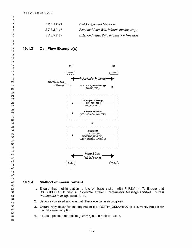
3GPP2 C.S0058-0 v1.0 1 2 3 4 5 6 7 8 9
10 11 12 13 14 15 16 17 18 19 20 21 22 23 24 25 26 27 28 29 30 31 32 33 34 35 36 37 38 39 40 41 42 43 44 45 46 47 48 49 50 51 52 53 54 55 56 57 58
3.7.3.3.2.43 Call Assignment Message
3.7.3.3.2.44 Extended Alert With Information Message
3.7.3.3.2.45 Extended Flash With Information Message
10.1.3 Call Flow Example(s)
Enhanced Origination Message(Data SOY, TAGY)
SCM / GHDM / UHDM (SCR += (Data SOY, CON_REFY)
BSMS
Traffic Traffic
TrafficTraffic
Call Assignment Message (RESPONSE_IND=1,TAGY, CON_REFY)
SCM/ UHDM (CC_INFO_INCL=1,
RESPONSE_IND=1, TAGY SCR += (Data SOY, CON_REFY))
OR
MS initiates datacalll setup
Voice Call in Progress
Voice & DataCall in Progress
10.1.4 Method of measurement 1.
2.
3.
4.
Ensure that mobile station is idle on base station with P_REV >= 7. Ensure that CS_SUPPORTED field in Extended System Parameters Message/ANSI-41 System Parameters Message is set to ‘1’.
Set up a voice call and wait until the voice call is in progress.
Ensure retry delay for call origination (i.e. RETRY_DELAYs[001]) is currently not set for the data service option.
59 60
10-2
Initiate a packet data call (e.g. SO33) at the mobile station.
3GPP2 C.S0058-0 v1.0 1 2 3 4 5 6 7 8 9 10 11 12 13 14 15 16 17 18 19 20 21 22 23 24 25 26 27 28 29 30 31 32 33 34 35 36 37 38 39 40 41 42 43 44 45 46 47 48 49 50 51 52 53 54 55 56 57 58
5. Verify that the mobile station sends an Enhanced Origination Message with the following fields set as follows:
FIELD VALUE
TAG ‘0001’
SR_ID ‘001’ or ‘010’.
SERVICE_OPTION Service Option corresponding to the data call (e.g. SO33)
DRS ‘1’ (data ready to send)
6.
7.
a.
b.
Verify that data call is set up and data call user traffic is exchanged successfully. Verify that the voice call is not dropped.
Repeat steps 2 to 6 with the following modifications:
In step 2, set up a teleservice call (e.g. SMS, Position Determination, etc.) requiring dedicated channels.
In step 6, the teleservice call is not dropped after the establishment of the data call.
10.1.5 Minimum Standard The mobile station shall successfully set up a mobile station initiated data call when a voice call or teleservice call is in progress, without dropping the call in progress.
10.2 Set up Mobile Station terminated Data Call while Voice Call or Teleservice Call is in Progress
10.2.1 Definition This test verifies that, when a voice call or teleservice call is already in progress, a mobile station terminated data call (for a dormant data session) can be established successfully.
10.2.2 Traceability (See [3]):
2.6.4.1.2.2.5 Waiting for Service Action Time Subfunction
2.6.4.1.12 Processing the Service Configuration Record
2.6.4.2 Traffic Channel Initialization Substate
2.6.4.3 Traffic Channel Substate
2.6.4.4 Release Substate
2.6.10 Call Control Processing
2.7.2.3.2.3 Flash with Information Message
2.7.2.3.2.32 Enhanced Origination Message
2.7.2.3.2.33 Extended Flash With Information Message 59 60
10-3
2.7.2.3.2.37 Call Cancel Message
2.7.2.3.2.29 Resource Release Request Message
3GPP2 C.S0058-0 v1.0 1 2 3 4 5 6 7 8 9
10 11 12 13 14 15 16 17 18 19 20 21 22 23 24 25 26 27 28 29 30 31 32 33 34 35 36 37 38 39 40 41 42 43 44 45 46 47 48 49 50 51 52 53 54 55 56 57 58
2.7.2.3.2.30 Resource Release Request Mini Message
2.7.3.4 Mobile Station Reject Order
2.7.4.25 Capability Information
3.6.4.1.7 Response to Enhanced Origination Message
3.6.4.1.8 Processing Resource Release Request Message and Resource Release Request Mini Message
3.6.4.2 Traffic Channel Initialization Substate
3.6.4.3 Traffic Channel Substate
3.6.8 Call Control Processing
3.7.2.3.2.13 Extended System Parameters Message
3.7.2.3.2.30 ANSI-41 System Parameters Message
3.7.3.3.2.26 Analog Handoff Direction Message
3.7.3.3.2.20 Service Connect Message
3.7.3.3.2.36 Universal Handoff Direction Message
3.7.3.3.2.43 Call Assignment Message
3.7.3.3.2.44 Extended Alert With Information Message
3.7.3.3.2.46 Extended Flash With Information Message
10.2.3 Call Flow Example(s)
59 60
10-4
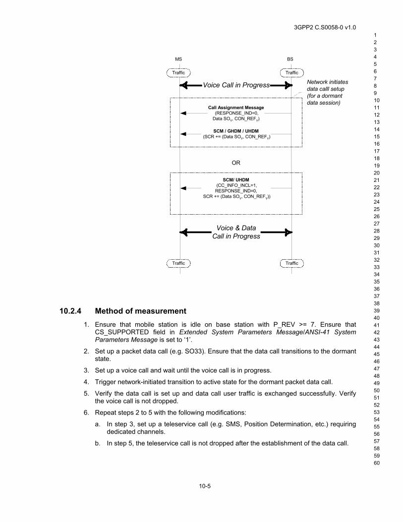
3GPP2 C.S0058-0 v1.0 1 2 3 4 5 6 7 8 9 10 11 12 13 14 15 16 17 18 19 20 21 22 23 24 25 26 27 28 29 30 31 32 33 34 35 36 37 38 39 40 41 42 43 44 45 46 47 48 49 50 51 52 53 54 55 56 57 58
SCM / GHDM / UHDM (SCR += (Data SOY, CON_REFY)
BSMS
Traffic Traffic
TrafficTraffic
Call Assignment Message (RESPONSE_IND=0,Data SOY, CON_REFY)
SCM/ UHDM (CC_INFO_INCL=1,RESPONSE_IND=0,
SCR += (Data SOY, CON_REFY))
OR
Network initiatesdata calll setup(for a dormantdata session)
Voice Call in Progress
Voice & DataCall in Progress
10.2.4 Method of measurement 1.
2.
3.
4.
5.
6.
a.
b.
Ensure that mobile station is idle on base station with P_REV >= 7. Ensure that CS_SUPPORTED field in Extended System Parameters Message/ANSI-41 System Parameters Message is set to ‘1’.
Set up a packet data call (e.g. SO33). Ensure that the data call transitions to the dormant state.
Set up a voice call and wait until the voice call is in progress.
Trigger network-initiated transition to active state for the dormant packet data call.
Verify the data call is set up and data call user traffic is exchanged successfully. Verify the voice call is not dropped.
Repeat steps 2 to 5 with the following modifications:
In step 3, set up a teleservice call (e.g. SMS, Position Determination, etc.) requiring dedicated channels.
In step 5, the teleservice call is not dropped after the establishment of the data call.
59 60
10-5
3GPP2 C.S0058-0 v1.0 1 2 3 4 5 6 7 8 9
10 11 12 13 14 15 16 17 18 19 20 21 22 23 24 25 26 27 28 29 30 31 32 33 34 35 36 37 38 39 40 41 42 43 44 45 46 47 48 49 50 51 52 53 54 55 56 57 58
10.2.5 Minimum Standard The mobile station shall be able to successfully set up mobile station terminated data call when voice call or teleservice call is in progress, without dropping the call in progress.
10.3 Set up Mobile Station Originated Voice Call while Data Call or Teleservice Call is in Progress
10.3.1 Definition This test verifies that, when a data call or teleservice call is already in progress, a mobile station originated voice call can be established successfully.
10.3.2 Traceability (See [3]):
2.6.4.1.2.2.5 Waiting for Service Action Time Subfunction
2.6.4.1.12 Processing the Service Configuration Record
2.6.4.2 Traffic Channel Initialization Substate
2.6.4.3 Traffic Channel Substate
2.6.4.4 Release Substate
2.6.10 Call Control Processing
2.7.2.3.2.3 Flash with Information Message
2.7.2.3.2.32 Enhanced Origination Message
2.7.2.3.2.33 Extended Flash With Information Message
2.7.2.3.2.37 Call Cancel Message
2.7.2.3.2.29 Resource Release Request Message
2.7.2.3.2.30 Resource Release Request Mini Message
2.7.3.4 Mobile Station Reject Order
2.7.4.25 Capability Information
3.6.4.1.7 Response to Enhanced Origination Message
3.6.4.1.8 Processing Resource Release Request Message and Resource Release Request Mini Message
3.6.4.2 Traffic Channel Initialization Substate
3.6.4.3 Traffic Channel Substate
3.6.8 Call Control Processing
3.7.2.3.2.13 Extended System Parameters Message
3.7.2.3.2.30 ANSI-41 System Parameters Message
3.7.3.3.2.26 Analog Handoff Direction Message
59 60
10-6
3.7.3.3.2.20 Service Connect Message
3.7.3.3.2.36 Universal Handoff Direction Message
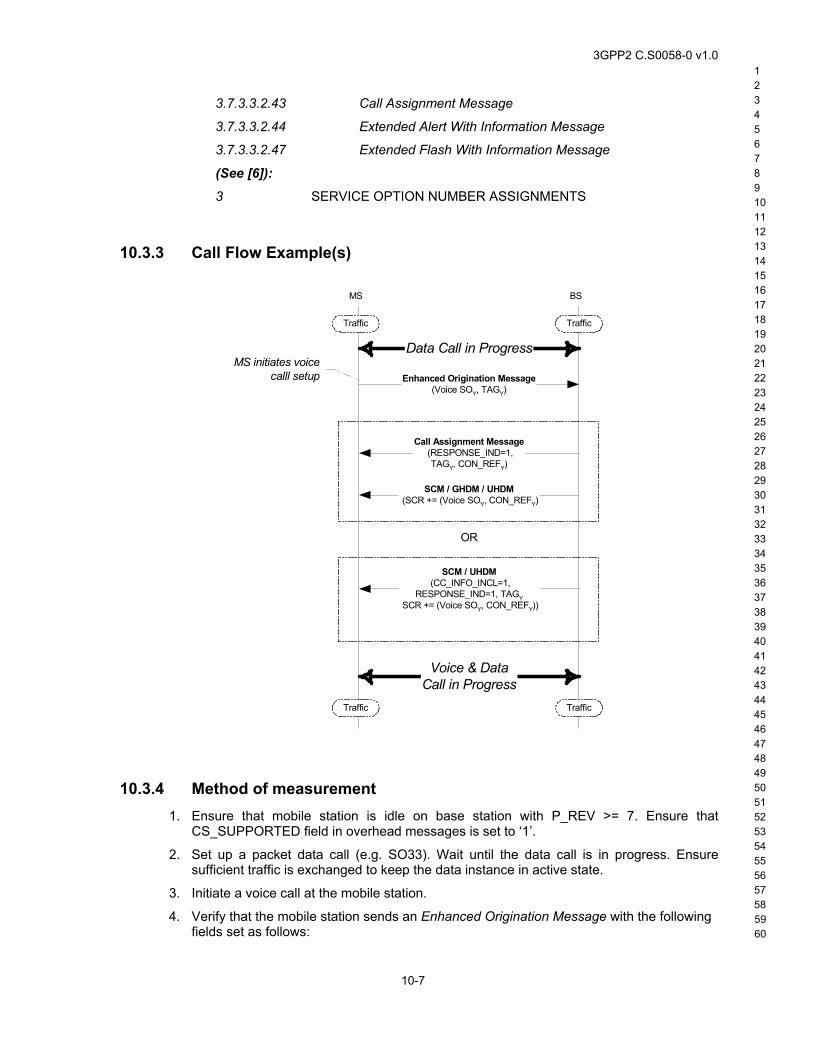
3GPP2 C.S0058-0 v1.0 1 2 3 4 5 6 7 8 9 10 11 12 13 14 15 16 17 18 19 20 21 22 23 24 25 26 27 28 29 30 31 32 33 34 35 36 37 38 39 40 41 42 43 44 45 46 47 48 49 50 51 52 53 54 55 56 57 58
3.7.3.3.2.43 Call Assignment Message
3.7.3.3.2.44 Extended Alert With Information Message
3.7.3.3.2.47 Extended Flash With Information Message
(See [6]):
3 SERVICE OPTION NUMBER ASSIGNMENTS
10.3.3 Call Flow Example(s)
Enhanced Origination Message(Voice SOY, TAGY)
SCM / GHDM / UHDM (SCR += (Voice SOY, CON_REFY)
BSMS
Traffic Traffic
TrafficTraffic
Call Assignment Message (RESPONSE_IND=1,
TAGY, CON_REFY)
SCM / UHDM (CC_INFO_INCL=1,
RESPONSE_IND=1, TAGY SCR += (Voice SOY, CON_REFY))
OR
MS initiates voicecalll setup
Data Call in Progress
Voice & DataCall in Progress
10.3.4 Method of measurement 1.
2.
3.
4.
Ensure that mobile station is idle on base station with P_REV >= 7. Ensure that CS_SUPPORTED field in overhead messages is set to ‘1’.
Set up a packet data call (e.g. SO33). Wait until the data call is in progress. Ensure sufficient traffic is exchanged to keep the data instance in active state.
Initiate a voice call at the mobile station.
59 60
10-7
Verify that the mobile station sends an Enhanced Origination Message with the following fields set as follows:
3GPP2 C.S0058-0 v1.0 1 2 3 4 5 6 7 8 9
10 11 12 13 14 15 16 17 18 19 20 21 22 23 24 25 26 27 28 29 30 31 32 33 34 35 36 37 38 39 40 41 42 43 44 45 46 47 48 49 50 51 52 53 54 55 56 57 58
Field Value
TAG ‘0001’
SR_ID ‘010’
SERVICE_OPTION Service Option corresponding to the voice call (e.g. SO 3)
5.
6.
a.
b.
Verify the voice call is set up and voice call user traffic is exchanged successfully. Verify the data call is not dropped.
Repeat steps 2 to 5 with the following modifications:
In step 2, set up a teleservice call (e.g. SMS, Position Determination, etc.) requiring dedicated channels.
In step 5, the teleservice call is not dropped after the establishment of the voice call.
10.3.5 Minimum Standard The mobile station shall be able to successfully set up mobile station originated voice call when data call or teleservice call is in progress, without dropping the call in progress.
10.4 Set up Mobile Station terminated Voice Call while Data Call or Teleservice Call is in Progress
10.4.1 Definition This test verifies that, when a data call or teleservice call is already in progress, a mobile station terminated voice call can be established successfully.
10.4.2 Traceability (See [3]):
2.6.4.1.2.2.5 Waiting for Service Action Time Subfunction
2.6.4.1.12 Processing the Service Configuration Record
2.6.4.2 Traffic Channel Initialization Substate
2.6.4.3 Traffic Channel Substate
2.6.4.4 Release Substate
2.6.10 Call Control Processing
2.7.2.3.2.3 Flash with Information Message
2.7.2.3.2.32 Enhanced Origination Message
2.7.2.3.2.33 Extended Flash With Information Message
2.7.2.3.2.37 Call Cancel Message
2.7.2.3.2.29 Resource Release Request Message
59 60
10-8
2.7.2.3.2.30 Resource Release Request Mini Message
2.7.3.4 Mobile Station Reject Order

3GPP2 C.S0058-0 v1.0 1 2 3 4 5 6 7 8 9 10 11 12 13 14 15 16 17 18 19 20 21 22 23 24 25 26 27 28 29 30 31 32 33 34 35 36 37 38 39 40 41 42 43 44 45 46 47 48 49 50 51 52 53 54 55 56 57 58
2.7.4.25 Capability Information
3.6.4.1.7 Response to Enhanced Origination Message
3.6.4.1.8 Processing Resource Release Request Message and Resource Release Request Mini Message
3.6.4.2 Traffic Channel Initialization Substate
3.6.4.3 Traffic Channel Substate
3.6.8 Call Control Processing
3.7.2.3.2.13 Extended System Parameters Message
3.7.2.3.2.30 ANSI-41 System Parameters Message
3.7.3.3.2.26 Analog Handoff Direction Message
3.7.3.3.2.20 Service Connect Message
3.7.3.3.2.36 Universal Handoff Direction Message
3.7.3.3.2.43 Call Assignment Message
3.7.3.3.2.44 Extended Alert With Information Message
3.7.3.3.2.48 Extended Flash With Information Message
59 60
10-9
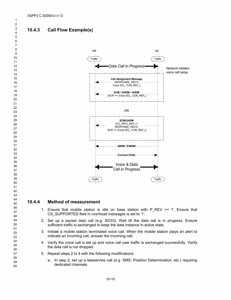
3GPP2 C.S0058-0 v1.0 1 2 3 4 5 6 7 8 9
10 11 12 13 14 15 16 17 18 19 20 21 22 23 24 25 26 27 28 29 30 31 32 33 34 35 36 37 38 39 40 41 42 43 44 45 46 47 48 49 50 51 52 53 54 55 56 57 58
10.4.3 Call Flow Example(s)
SCM / GHDM / UHDM (SCR += (Voice SOY, CON_REFY)
BSMS
Traffic Traffic
TrafficTraffic
Call Assignment Message (RESPONSE_IND=0,
Voice SOY, CON_REFY)
SCM/UHDM (CC_INFO_INCL=1,RESPONSE_IND=0,
SCR += (Voice SOY, CON_REFY))
OR
Network initiatesvoice call setup
Data Call in Progress
Voice & DataCall in Progress
AWIM / EAWIM
Connect Order
10.4.4 Method of measurement 1.
2.
3.
4.
5.
a.
Ensure that mobile station is idle on base station with P_REV >= 7. Ensure that CS_SUPPORTED field in overhead messages is set to ‘1’.
Set up a packet data call (e.g. SO33). Wait till the data call is in progress. Ensure sufficient traffic is exchanged to keep the data instance in active state.
Initiate a mobile station terminated voice call. When the mobile station plays an alert to indicate an incoming call, answer the incoming call.
Verify the voice call is set up and voice call user traffic is exchanged successfully. Verify the data call is not dropped.
Repeat steps 2 to 4 with the following modifications:
59 60
10-10
In step 2, set up a teleservice call (e.g. SMS, Position Determination, etc.) requiring dedicated channels.
3GPP2 C.S0058-0 v1.0 1 2 3 4 5 6 7 8 9 10 11 12 13 14 15 16 17 18 19 20 21 22 23 24 25 26 27 28 29 30 31 32 33 34 35 36 37 38 39 40 41 42 43 44 45 46 47 48 49 50 51 52 53 54 55 56 57 58
b. In step 4, the teleservice call is not dropped after the establishment of the voice call.
10.4.5 Minimum Standard The mobile station shall be able to successfully set up mobile station terminated voice call when data call or teleservice call is in progress, without dropping the call in progress.
10.5 Mobile Station Release of a Single Call While Voice and Data Calls are in Progress
10.5.1 Definition This test verifies that, when both voice and data calls are in progress, mobile station can release one of the calls successfully and the other call continues uninterrupted.
10.5.2 Traceability (See [3]):
2.6.4.1.2.2.5 Waiting for Service Action Time Subfunction
2.6.4.1.12 Processing the Service Configuration Record
2.6.4.2 Traffic Channel Initialization Substate
2.6.4.3 Traffic Channel Substate
2.6.4.4 Release Substate
2.6.10 Call Control Processing
2.7.2.3.2.3 Flash with Information Message
2.7.2.3.2.32 Enhanced Origination Message
2.7.2.3.2.33 Extended Flash With Information Message
2.7.2.3.2.37 Call Cancel Message
2.7.2.3.2.29 Resource Release Request Message
2.7.2.3.2.30 Resource Release Request Mini Message
2.7.3.4 Mobile Station Reject Order
2.7.4.25 Capability Information
3.6.4.1.7 Response to Enhanced Origination Message
3.6.4.1.8 Processing Resource Release Request Message and Resource Release Request Mini Message
3.6.4.2 Traffic Channel Initialization Substate
3.6.4.3 Traffic Channel Substate
3.6.8 Call Control Processing
3.7.2.3.2.13 Extended System Parameters Message
3.7.2.3.2.30 ANSI-41 System Parameters Message 59 60
10-11
3.7.3.3.2.26 Analog Handoff Direction Message
3.7.3.3.2.20 Service Connect Message
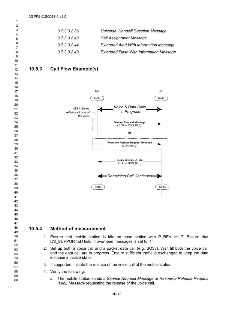
3GPP2 C.S0058-0 v1.0 1 2 3 4 5 6 7 8 9
10 11 12 13 14 15 16 17 18 19 20 21 22 23 24 25 26 27 28 29 30 31 32 33 34 35 36 37 38 39 40 41 42 43 44 45 46 47 48 49 50 51 52 53 54 55 56 57 58
3.7.3.3.2.36 Universal Handoff Direction Message
3.7.3.3.2.43 Call Assignment Message
3.7.3.3.2.44 Extended Alert With Information Message
3.7.3.3.2.49 Extended Flash With Information Message
10.5.3 Call Flow Example(s)
SCM / GHDM / UHDM (SCR -= CON_REFY)
BSMS
Traffic Traffic
TrafficTraffic
MS initiatesrelease of one of
the calls
Voice & Data Calls in Progress
Remaining Call Continues
Service Request Message( SCR -= CON_REFY)
Resource Release Request Message(CON_REFY)
or
10.5.4 Method of measurement 1.
2.
3.
4.
a.
Ensure that mobile station is idle on base station with P_REV >= 7. Ensure that CS_SUPPORTED field in overhead messages is set to ‘1’.
Set up both a voice call and a packet data call (e.g. SO33). Wait till both the voice call and the data call are in progress. Ensure sufficient traffic is exchanged to keep the data instance in active state.
If supported, initiate the release of the voice call at the mobile station.
59 60
10-12
Verify the following:
The mobile station sends a Service Request Message or Resource Release Request (Mini) Message requesting the release of the voice call.
3GPP2 C.S0058-0 v1.0 1 2 3 4 5 6 7 8 9 10 11 12 13 14 15 16 17 18 19 20 21 22 23 24 25 26 27 28 29 30 31 32 33 34 35 36 37 38 39 40 41 42 43 44 45 46 47 48 49 50 51 52 53 54 55 56 57 58
1) If the mobile station sends a Service Request Message, the service option connection record corresponding to the voice call is omitted from the Service Configuration information record included in this message.
2) If the mobile station sends a Resource Release Request (Mini) Message, the following fields shall be set as follows:
Field Value
GATING_DISCONNECT_IND ‘0’ (release of a call requested)
CON_REF Connection reference corresponding to the voice call to be released
c.
d.
e.
5.
Upon receiving the Service Request Message or Resource Release Request (Mini) Message requesting the release of the voice call, the base station sends a Service Connect Message, General Handoff Direction Message (with a SCR), or Universal Handoff Direction Message (with a SCR) as follows:
1) The service option connection record corresponding to the voice call is omitted from the Service Configuration information record included in this message.
At the action time of the Service Connect Message, General Handoff Direction Message, or Universal Handoff Direction Message used to release the voice call, the voice traffic no longer flows.
The data call is not dropped.
Repeat steps 1 though 4 with the following exception: in step 3, initiate the release of the data call at the mobile station. All the expected results are as in step 4 with the difference that the call being released is the data call.
10.5.5 Minimum Standard The mobile station shall be able to successfully release one of the two calls in progress, without dropping the other call in progress.
10.6 Base Station Release of a Single Call While Voice and Data Calls are in Progress
10.6.1 Definition This test verifies that, when both voice and data calls are in progress, base station can release one of the calls successfully and the other call continues uninterrupted.
10.6.2 Traceability (See [3]):
2.6.4.1.2.2.5 Waiting for Service Action Time Subfunction
2.6.4.1.12 Processing the Service Configuration Record
2.6.4.2 Traffic Channel Initialization Substate
2.6.4.3 Traffic Channel Substate 59 60
10-13
2.6.4.4 Release Substate
2.6.10 Call Control Processing
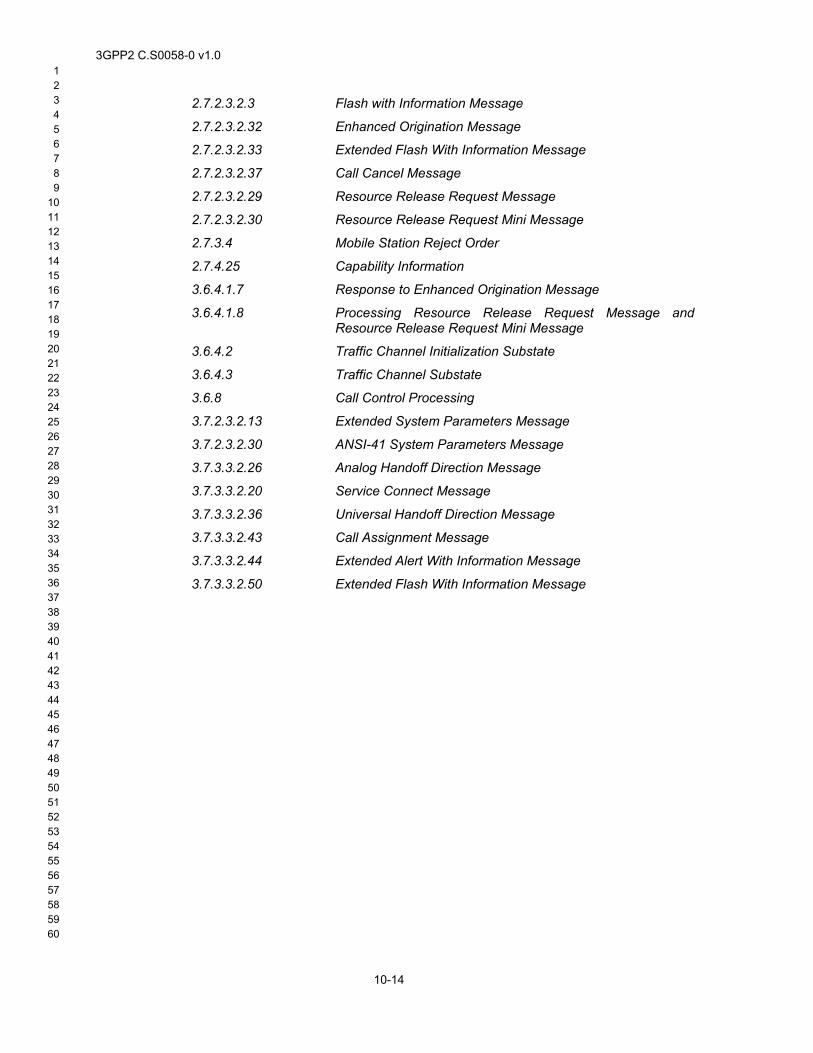
3GPP2 C.S0058-0 v1.0 1 2 3 4 5 6 7 8 9
10 11 12 13 14 15 16 17 18 19 20 21 22 23 24 25 26 27 28 29 30 31 32 33 34 35 36 37 38 39 40 41 42 43 44 45 46 47 48 49 50 51 52 53 54 55 56 57 58
2.7.2.3.2.3 Flash with Information Message
2.7.2.3.2.32 Enhanced Origination Message
2.7.2.3.2.33 Extended Flash With Information Message
2.7.2.3.2.37 Call Cancel Message
2.7.2.3.2.29 Resource Release Request Message
2.7.2.3.2.30 Resource Release Request Mini Message
2.7.3.4 Mobile Station Reject Order
2.7.4.25 Capability Information
3.6.4.1.7 Response to Enhanced Origination Message
3.6.4.1.8 Processing Resource Release Request Message and Resource Release Request Mini Message
3.6.4.2 Traffic Channel Initialization Substate
3.6.4.3 Traffic Channel Substate
3.6.8 Call Control Processing
3.7.2.3.2.13 Extended System Parameters Message
3.7.2.3.2.30 ANSI-41 System Parameters Message
3.7.3.3.2.26 Analog Handoff Direction Message
3.7.3.3.2.20 Service Connect Message
3.7.3.3.2.36 Universal Handoff Direction Message
3.7.3.3.2.43 Call Assignment Message
3.7.3.3.2.44 Extended Alert With Information Message
3.7.3.3.2.50 Extended Flash With Information Message
59 60
10-14
3GPP2 C.S0058-0 v1.0 1 2 3 4 5 6 7 8 9 10 11 12 13 14 15 16 17 18 19 20 21 22 23 24 25 26 27 28 29 30 31 32 33 34 35 36 37 38 39 40 41 42 43 44 45 46 47 48 49 50 51 52 53 54 55 56 57 58
10.6.3 Call Flow Example(s)
SCM / GHDM / UHDM (SCR -= CON_REFY)
BSMS
Traffic Traffic
TrafficTraffic
Network initiatesrelease of one ofthe calls
Voice & Data Calls in Progress
Remaining Call Continues
10.6.4 Method of measurement 1.
2.
3.
4.
a.
b.
Ensure that mobile station is idle on base station with P_REV >= 7. Ensure that CS_SUPPORTED field in overhead messages is set to ‘1’.
Set up both a voice call and a packet data call (e.g. SO33). Wait till both the voice call and the data call are in progress. Ensure sufficient traffic is exchanged to keep the data instance in active state.
Trigger a network-initiated release of the voice call.
Verify the following:
The base station sends a Service Connect Message, General Handoff Direction Message (with a SCR), or Universal Handoff Direction Message (with a SCR), where the service option connection record corresponding to the voice call is omitted from the Service Configuration information record included in this message.
59 60
10-15
At the action time of the Service Connect Message, General Handoff Direction Message, or Universal Handoff Direction Message used to release the voice call, the voice traffic no longer flows.
3GPP2 C.S0058-0 v1.0 1 2 3 4 5 6 7 8 9
10 11 12 13 14 15 16 17 18 19 20 21 22 23 24 25 26 27 28 29 30 31 32 33 34 35 36 37 38 39 40 41 42 43 44 45 46 47 48 49 50 51 52 53 54 55 56 57 58
c.
5.
2.7.2.3.2.3 Flash with Information Message
The data call is not dropped.
Repeat steps 1 though 4 with the following exception: in step 3, initiate the release of the data call at the base station if possible (e.g. if inactivity timer at base station is smaller than inactivity timer at mobile station, then not exchanging any data would result in base station releasing a data call). All the expected results are as in step 4 with the difference that the call being released is the data call.
10.6.5 Minimum Standard The mobile station shall be able to successfully release one of the two calls in progress, without dropping the other call in progress.
10.7 Correct Handling of Call Control Signaling 10.7.1 Definition
This test verifies that, when one or more calls are in progress, mobile station initiated and network initiated call control signaling messages are handled correctly.
10.7.2 Traceability (See [3]):
2.6.4.1.2.2.5 Waiting for Service Action Time Subfunction
2.6.4.1.12 Processing the Service Configuration Record
2.6.4.2 Traffic Channel Initialization Substate
2.6.4.3 Traffic Channel Substate
2.6.4.4 Release Substate
2.6.10 Call Control Processing
2.7.2.3.2.32 Enhanced Origination Message
2.7.2.3.2.33 Extended Flash With Information Message
2.7.2.3.2.37 Call Cancel Message
2.7.2.3.2.29 Resource Release Request Message
2.7.2.3.2.30 Resource Release Request Mini Message
2.7.3.4 Mobile Station Reject Order
2.7.4.25 Capability Information
3.6.4.1.7 Response to Enhanced Origination Message
3.6.4.1.8 Processing Resource Release Request Message and Resource Release Request Mini Message
3.6.4.2 Traffic Channel Initialization Substate
3.6.4.3 Traffic Channel Substate
59 60
10-16
3.6.8 Call Control Processing
3.7.2.3.2.13 Extended System Parameters Message
3GPP2 C.S0058-0 v1.0 1 2 3 4 5 6 7 8 9 10 11 12 13 14 15 16 17 18 19 20 21 22 23 24 25 26 27 28 29 30 31 32 33 34 35 36 37 38 39 40 41 42 43 44 45 46 47 48 49 50 51 52 53 54 55 56 57 58
3.7.2.3.2.30 ANSI-41 System Parameters Message
3.7.3.3.2.26 Analog Handoff Direction Message
3.7.3.3.2.20 Service Connect Message
3.7.3.3.2.36 Universal Handoff Direction Message
3.7.3.3.2.43 Call Assignment Message
3.7.3.3.2.44 Extended Alert With Information Message
3.7.3.3.2.51 Extended Flash With Information Message
59 60
10-17
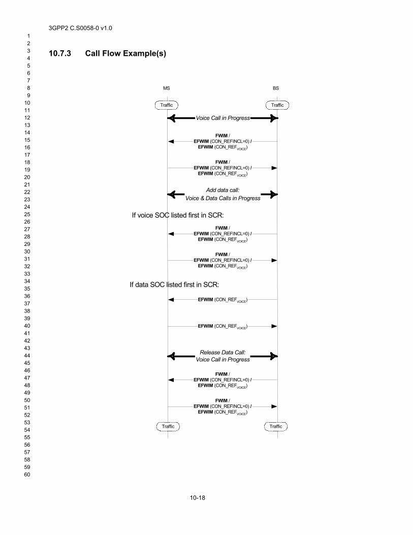
3GPP2 C.S0058-0 v1.0 1 2 3 4 5 6 7 8 9
10 11 12 13 14 15 16 17 18 19 20 21 22 23 24 25 26 27 28 29 30 31 32 33 34 35 36 37 38 39 40 41 42 43 44 45 46 47 48 49 50 51 52 53 54 55 56 57 58
10.7.3 Call Flow Example(s)
BSMS
Traffic Traffic
TrafficTraffic
Voice Call in Progress
FWIM /EFWIM (CON_REFINCL=0) /
EFWIM (CON_REFVOICE)
FWIM /EFWIM (CON_REFINCL=0) /
EFWIM (CON_REFVOICE)
Add data call:Voice & Data Calls in Progress
FWIM /EFWIM (CON_REFINCL=0) /
EFWIM (CON_REFVOICE)
FWIM /EFWIM (CON_REFINCL=0) /
EFWIM (CON_REFVOICE)
EFWIM (CON_REFVOICE)
EFWIM (CON_REFVOICE)
Release Data Call:Voice Call in Progress
FWIM /EFWIM (CON_REFINCL=0) /
EFWIM (CON_REFVOICE)
FWIM /EFWIM (CON_REFINCL=0) /
EFWIM (CON_REFVOICE)
If voice SOC listed first in SCR:
If data SOC listed first in SCR:
59 60
10-18
3GPP2 C.S0058-0 v1.0 1 2 3 4 5 6 7 8 9 10 11 12 13 14 15 16 17 18 19 20 21 22 23 24 25 26 27 28 29 30 31 32 33 34 35 36 37 38 39 40 41 42 43 44 45 46 47 48 49 50 51 52 53 54 55 56 57 58
1.
2.
3.
4.
a.
b.
5.
6.
a.
b.
7.
8.
9.
a.
b.
10.7.4 Method of measurement Ensure that mobile station is idle on base station with P_REV >= 7. Ensure that CS_SUPPORTED field in overhead messages is set to ‘1’.
Set up a voice call and wait until the voice call is in progress.
If applicable, trigger an action at the mobile station that will result in either a Flash With Information Message or Extended Flash With Information Message for a voice call being transmitted to the base station (e.g. Trigger an action that utilizes the Keypad Facility information record).
Verify the following:
The mobile station sends a Flash With Information Message, an Extended Flash With Information Message with the CON_REF_INCL field set to ‘0’, or an Extended Flash With Information Message with the CON_REF field set to the connection reference corresponding to the voice call.
If applicable, the information record is delivered correctly in the network.
If applicable, trigger an action at the network that will result in either a Flash With Information Message or Extended Flash With Information Message being transmitted to the mobile station (e.g. Trigger an action that utilizes the Display information record).
Verify the following:
The base station sends a Flash With Information Message, an Extended Flash With Information Message with the CON_REF_INCL field set to ‘0’, or an Extended Flash With Information Message with the CON_REF field set to the connection reference corresponding to the voice call.
The information record is correctly handled in the mobile station.
Set up a mobile station originated or mobile station terminated packet data call (e.g. SO33). When the base station sends a Service Connect Message, General Handoff Direction Message, or Universal Handoff Direction Message to establish the service option connection corresponding to the data call, note whether the service option connection corresponding to the voice call or data call is listed as the first entry in the SCR.
If applicable, trigger an action at the mobile station that will result in either a Flash With Information Message or Extended Flash With Information Message for a voice call being transmitted to the base station (e.g. Trigger an action that utilizes the Keypad Facility information record).
Verify the following:
If the service option connection corresponding to the voice call is listed as the first entry in the SCR:
1. The mobile station sends a Flash With Information Message, an Extended Flash With Information Message with the CON_REF_INCL field set to ‘0’, or an Extended Flash With Information Message with the CON_REF field set to the connection reference corresponding to the voice call.
2. If applicable, the information record is delivered correctly in the network.
If the service option connection corresponding to the data call is listed as the first entry in the SCR:
59 60
10-19
3GPP2 C.S0058-0 v1.0 1 2 3 4 5 6 7 8 9
10 11 12 13 14 15 16 17 18 19 20 21 22 23 24 25 26 27 28 29 30 31 32 33 34 35 36 37 38 39 40 41 42 43 44 45 46 47 48 49 50 51 52 53 54 55 56 57 58
10.
11.
12.
13.
14.
a.
b.
15.
16.
a.
1. The mobile station sends an (Extended) Flash With Information Message with the CON_REF field set to the connection reference corresponding to the voice call.
2. If applicable, the information record is delivered correctly in the network.
If applicable, trigger an action at the network that will result in either a Flash With Information Message or Extended Flash With Information Message for a voice call being transmitted to the mobile station (e.g. Trigger an action that utilizes the Display information record).
Verify the following:
a. If the service option connection corresponding to the voice call is listed as the first entry in the SCR:
1. The base station sends a Flash With Information Message, an Extended Flash With Information Message with the CON_REF_INCL field set to ‘0’, or an Extended Flash With Information Message with the CON_REF field set to the connection reference corresponding to the voice call.
2. The information record is correctly handled in the mobile station.
b. If the service option connection corresponding to the data call is listed as the first entry in the SCR:
1. The base station sends an Extended Flash With Information Message with the CON_REF field set to the connection reference corresponding to the voice call.
2. The information record is correctly handled in the mobile station.
Perform a mobile station initiated or base station initiated release of the data call. Wait till this operation is successful.
If applicable, trigger an action at the mobile station that will result in either a Flash With Information Message or Extended Flash With Information Message for a voice call being transmitted to the base station (e.g. Trigger an action that utilizes the Keypad Facility information record).
Verify the following:
The mobile station sends a Flash With Information Message, an Extended Flash With Information Message with the CON_REF_INCL field set to ‘0’, or an Extended Flash With Information Message with the CON_REF field set to the connection reference corresponding to the voice call.
If applicable, the information record is delivered correctly in the network.
If applicable, trigger an action at the network that will result in either a Flash With Information Message or Extended Flash With Information Message being transmitted to the mobile station for a voice call (e.g. Trigger an action that utilizes the Display information record).
Verify the following:
59 60
10-20
The base station sends a Flash With Information Message, an Extended Flash With Information Message with the CON_REF_INCL field set to ‘0’, or an Extended Flash With Information Message with the CON_REF field set to the connection reference corresponding to the voice call.
3GPP2 C.S0058-0 v1.0 1 2 3 4 5 6 7 8 9 10 11 12 13 14 15 16 17 18 19 20 21 22 23 24 25 26 27 28 29 30 31 32 33 34 35 36 37 38 39 40 41 42 43 44 45 46 47 48 49 50 51 52 53 54 55 56 57 58
b. The information record is correctly handled in the mobile station.
10.7.5 Minimum Standard The mobile station shall be able to correctly send and receive call control signaling when one or two calls are in progress.
10.8 Release A Mobile Station in Concurrent Calls with a Release A Base Station Hand off to Pre-Release A Base Station
10.8.1 Definition This test verifies that, when a Release A mobile station currently in concurrent calls with a Release A base station is handed off to a Pre-Release A base station, only a single call is maintained and this call continues successfully.
10.8.2 Traceability (See [3]):
2.6.4.1.2.2.5 Waiting for Service Action Time Subfunction
2.6.4.1.12 Processing the Service Configuration Record
2.6.4.2 Traffic Channel Initialization Substate
2.6.4.3 Traffic Channel Substate
2.6.4.4 Release Substate
2.6.10 Call Control Processing
2.7.2.3.2.3 Flash with Information Message
2.7.2.3.2.32 Enhanced Origination Message
2.7.2.3.2.33 Extended Flash With Information Message
2.7.2.3.2.37 Call Cancel Message
2.7.2.3.2.29 Resource Release Request Message
2.7.2.3.2.30 Resource Release Request Mini Message
2.7.3.4 Mobile Station Reject Order
2.7.4.25 Capability Information
3.6.4.1.7 Response to Enhanced Origination Message
3.6.4.1.8 Processing Resource Release Request Message and Resource Release Request Mini Message
3.6.4.2 Traffic Channel Initialization Substate
3.6.4.3 Traffic Channel Substate
3.6.8 Call Control Processing
3.7.2.3.2.13 Extended System Parameters Message 59 60
10-21
3.7.2.3.2.30 ANSI-41 System Parameters Message
3.7.3.3.2.26 Analog Handoff Direction Message
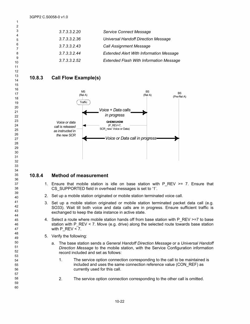
3GPP2 C.S0058-0 v1.0 1 2 3 4 5 6 7 8 9
10 11 12 13 14 15 16 17 18 19 20 21 22 23 24 25 26 27 28 29 30 31 32 33 34 35 36 37 38 39 40 41 42 43 44 45 46 47 48 49 50 51 52 53 54 55 56 57 58
3.7.3.3.2.20 Service Connect Message
3.7.3.3.2.36 Universal Handoff Direction Message
3.7.3.3.2.43 Call Assignment Message
3.7.3.3.2.44 Extended Alert With Information Message
3.7.3.3.2.52 Extended Flash With Information Message
10.8.3 Call Flow Example(s)
MS(Rel A)
Traffic
Voice + Data callsin progressGHDM/UHDM
(P_REV<7,SCR_new: Voice or Data)
Voice or datacall is releasedas instructed in
the new SCR
BS(Pre-Rel A)
Voice or Data call in progress
BS(Rel A)
10.8.4 Method of measurement 1.
2.
3.
4.
5.
a.
Ensure that mobile station is idle on base station with P_REV >= 7. Ensure that CS_SUPPORTED field in overhead messages is set to ‘1’.
Set up a mobile station originated or mobile station terminated voice call.
Set up a mobile station originated or mobile station terminated packet data call (e.g. SO33). Wait till both voice and data calls are in progress. Ensure sufficient traffic is exchanged to keep the data instance in active state.
Select a route where mobile station hands off from base station with P_REV >=7 to base station with P_REV < 7. Move (e.g. drive) along the selected route towards base station with P_REV < 7.
Verify the following:
The base station sends a General Handoff Direction Message or a Universal Handoff Direction Message to the mobile station, with the Service Configuration information record included and set as follows:
1. The service option connection corresponding to the call to be maintained is included and uses the same connection reference value (CON_REF) as currently used for this call.
59 60
10-22
2. The service option connection corresponding to the other call is omitted.

3GPP2 C.S0058-0 v1.0 1 2 3 4 5 6 7 8 9 10 11 12 13 14 15 16 17 18 19 20 21 22 23 24 25 26 27 28 29 30 31 32 33 34 35 36 37 38 39 40 41 42 43 44 45 46 47 48 49 50 51 52 53 54 55 56 57 58
b.
c.
At the action time of this message, the mobile station shall release the call corresponding to the omitted service option connection and hands off to the base station with P_REV < 7.
The remaining call continues successfully.
10.8.5 Minimum Standard The mobile station shall be able to correctly process inter P_REV handoff.
59 60
10-23

3GPP2 C.S0058-0 v1.0 1 2 3 4 5 6 7 8 9
10 11 12 13 14 15 16 17 18 19 20 21 22 23 24 25 26 27 28 29 30 31 32 33 34 35 36 37 38 39 40 41 42 43 44 45 46 47 48 49 50 51 52 53 54 55 56 57 58 59 60
10-24
No text.