Status of Fast Ignition Research - PPPL
23
PERSISTENT SURVEILLANCE FOR PIPELINE PROTECTION AND THREAT INTERDICTION Fusion Power Associates September 27-28, 2006 Washington, DC Status of Fast Ignition Research E. Mike Campbell Implosion to high density Efficient conversion : E laser “beam” of ~MeV electrons aimed at assembled fuel Efficient transport of hot electron energy to fuel Efficient deposition of electron energy in region of R~0.5 g cm -2 ( range), heating it to 5-10 keV Propagation of burn throughout assembled fuel: (need R>~1.8 g cm -2 ) Short pulse laser aimed and timed to implosion ICT/P2006-xxx FSC
Transcript of Status of Fast Ignition Research - PPPL

PERSISTENT SURVEILLANCE FORPIPELINE PROTECTION AND THREAT INTERDICTION
Fusion Power Associates
September 27-28, 2006
Washington, DC
Status of Fast Ignition Research
E. Mike Campbell
Implosion to highdensity
Efficient conversion:Elaser “beam” of ~MeVelectrons aimed atassembled fuel
Efficient transport of hotelectron energy to fuel
Efficient deposition ofelectron energy in regionof R~0.5 g cm-2 ( range),heating it to 5-10 keV
Propagation of burnthroughoutassembled fuel:(need R>~1.8 g cm-2)
Short pulse laseraimed and timed toimplosion
ICT/P2006-xxxFSC
Fast Ignition: Science of the “Extreme”-
High Energy Density Physics and Fusion
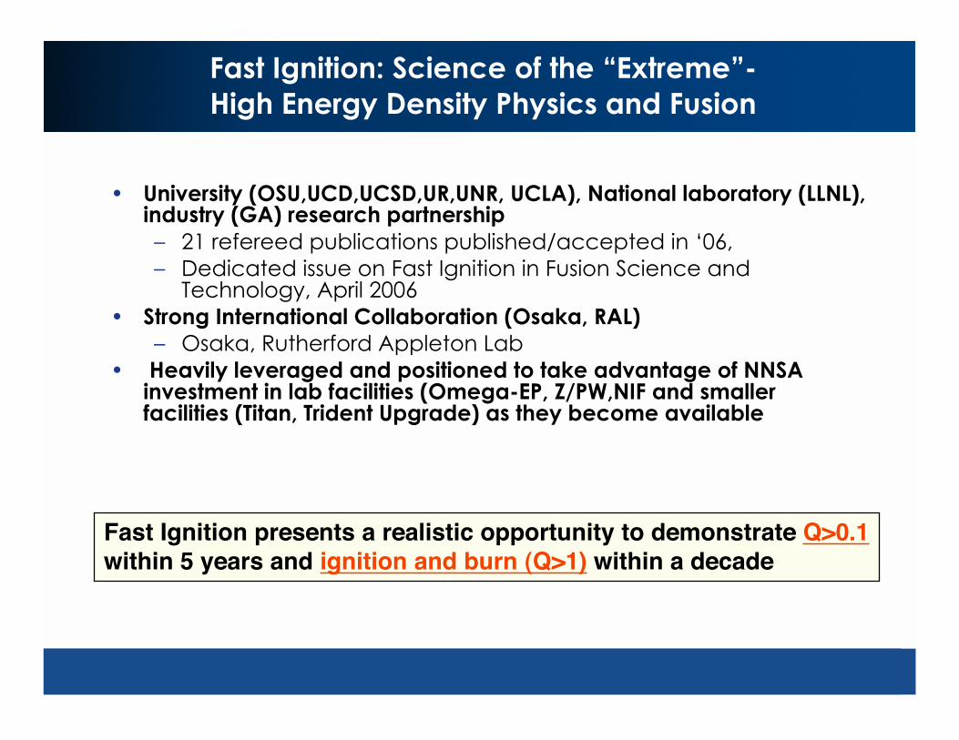
• University (OSU,UCD,UCSD,UR,UNR, UCLA), National laboratory (LLNL),industry (GA) research partnership
– 21 refereed publications published/accepted in ‘06,
– Dedicated issue on Fast Ignition in Fusion Science andTechnology, April 2006
• Strong International Collaboration (Osaka, RAL)
– Osaka, Rutherford Appleton Lab
• Heavily leveraged and positioned to take advantage of NNSAinvestment in lab facilities (Omega-EP, Z/PW,NIF and smallerfacilities (Titan, Trident Upgrade) as they become available
Fast Ignition presents a realistic opportunity to demonstrate Q>0.1within 5 years and ignition and burn (Q>1) within a decade

New Facilities under construction will allow FI physics toNew Facilities under construction will allow FI physics to
be explored under relevant conditionsbe explored under relevant conditions
FIREX-1
ZR and Petawatt
NIF/ARC
Omega-EP

FI benefits from international R&D efforts
• Reentrant cones cause
potential problems with
beta layering.
• DT surface can be formed
by filling foam
– Previous cryo-foam
experience at ILE
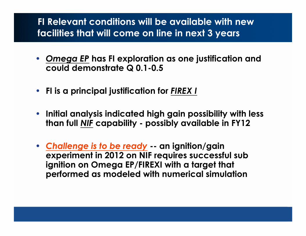
FI Relevant conditions will be available with new
facilities that will come on line in next 3 years
•• Omega EPOmega EP has FI exploration as one justification andcould demonstrate Q 0.1-0.5
• FI is a principal justification for FIREX I
• Initial analysis indicated high gain possibility with lessthan full NIFNIF capability - possibly available in FY12
•• Challenge is to be readyChallenge is to be ready -- an ignition/gainexperiment in 2012 on NIF requires successful subignition on Omega EP/FIREXI with a target thatperformed as modeled with numerical simulation
Log (g/cm3)
Lo
g
(K
)
0 1 2 3
8
7
6
5
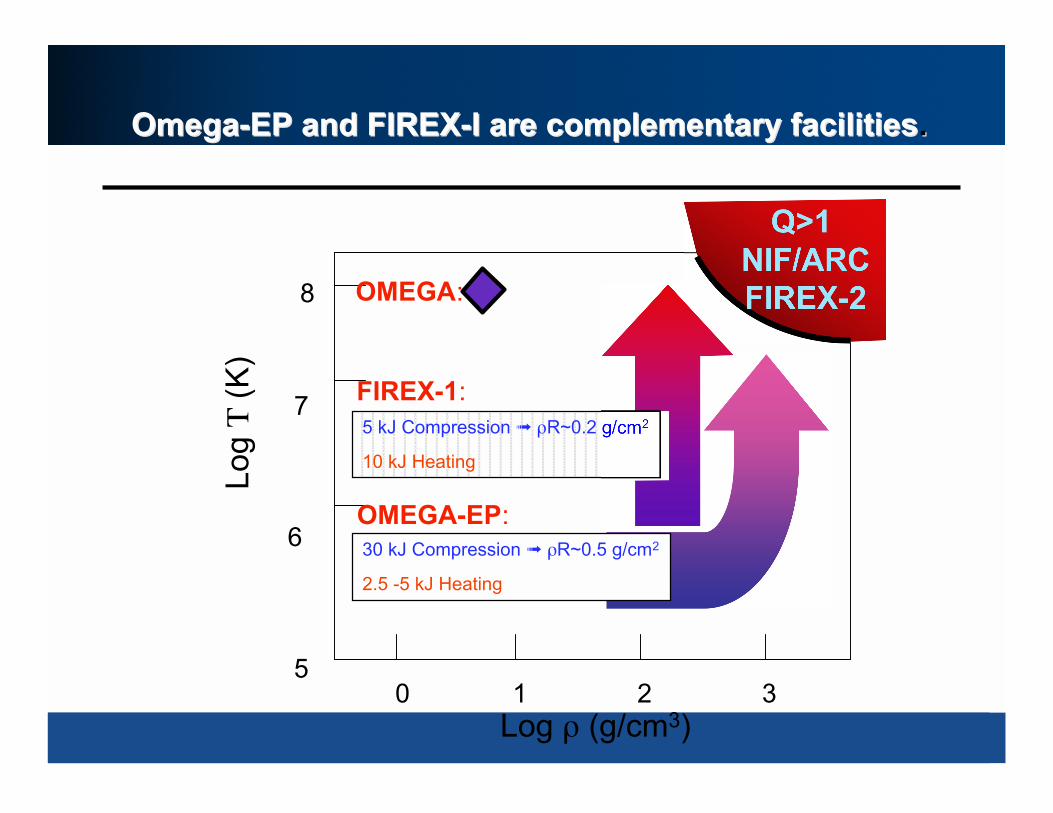
Omega-EP and FIREX-IOmega-EP and FIREX-I are complementary facilitiesare complementary facilities..
Q>1
NIF/ARC
FIREX-2
5 kJ Compression R~0.2 g/cm2
10 kJ Heating
FIREX-1:
30 kJ Compression R~0.5 g/cm2
2.5 -5 kJ Heating
OMEGA-EP:
OMEGA:
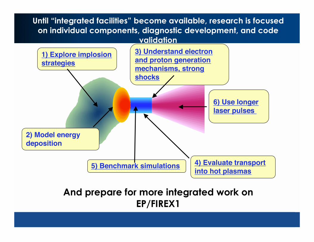
Until “integrated facilities” become available, research is focused
on individual components, diagnostic development, and code
validation
1) Explore implosionstrategies
3) Understand electronand proton generationmechanisms, strongshocks
4) Evaluate transportinto hot plasmas
5) Benchmark simulations
2) Model energydeposition
6) Use longerlaser pulses
And prepare for more integrated work on
EP/FIREX1

1) Design targets to optimize fast ignition requirements
Optimize with Low adiabat, low velocity, implosion
• Assembled fuel is nearly uniform
– Hot spot is <10% of volume
• Compression energy much lower– 750 kJ to assemble R=3 g/cc
• Dense fuel minimizes ignition energy
– 300-400 g/cc
Potential for gain >100 within NIF capability
Central Hot spot Fast ignition
R. Betti, Phys of Plasmas 12, 110702 (2006)
Fuel density at stagnation
From 1-D

Optimized fast-ignition cryo-targets are thick
shells of wetted foam with initial aspect ratio ~2
TC7378R. Betti and C. Zhou, Phys. Plasmas 12, 110702 (2005)
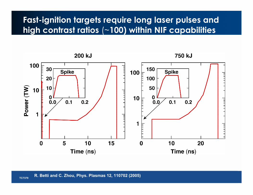
Fast-ignition targets require long laser pulses and
high contrast ratios (~100) within NIF capabilities
TC7379R. Betti and C. Zhou, Phys. Plasmas 12, 110702 (2005)
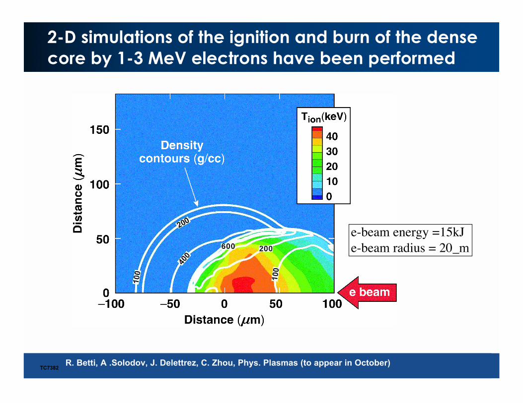
2-D simulations of the ignition and burn of the dense
core by 1-3 MeV electrons have been performed
TC7382
e-beam energy =15kJe-beam radius = 20_m
R. Betti, A .Solodov, J. Delettrez, C. Zhou, Phys. Plasmas (to appear in October)
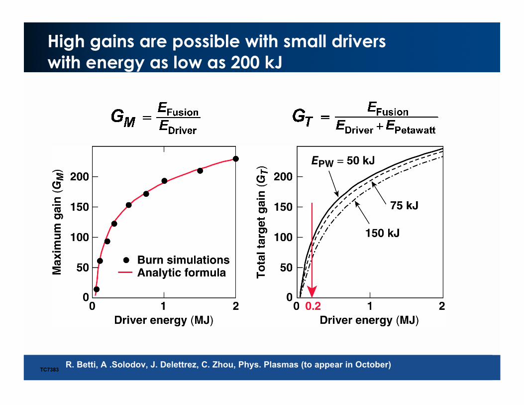
High gains are possible with small drivers
with energy as low as 200 kJ
TC7383R. Betti, A .Solodov, J. Delettrez, C. Zhou, Phys. Plasmas (to appear in October)
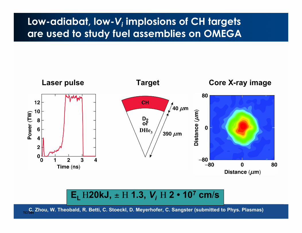
EL 20kJ, ± 1.3, Vi 2 • 107 cm/s
Low-adiabat, low-Vi implosions of CH targets
are used to study fuel assemblies on OMEGA
TC7384
or
DHe3
Core X-ray imageLaser pulse Target
C. Zhou, W. Theobald, R. Betti, C. Stoeckl, D. Meyerhofer, C. Sangster (submitted to Phys. Plasmas)
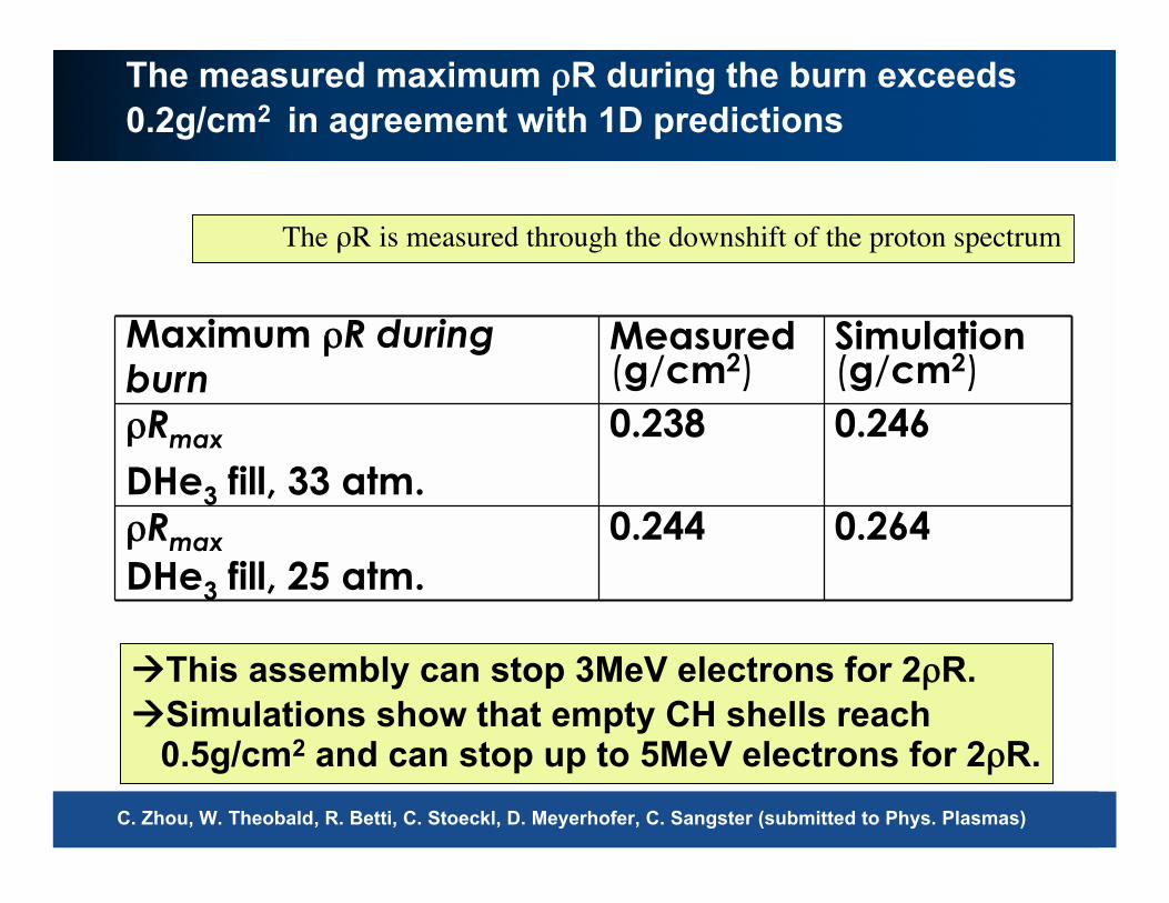
0.244
0.238
Measured(g/cm2)
0.264Rmax
DHe3 fill, 25 atm.
0.246Rmax
DHe3 fill, 33 atm.
Simulation(g/cm2)
Maximum R duringburn
The measured maximum R during the burn exceeds
0.2g/cm2 in agreement with 1D predictions
This assembly can stop 3MeV electrons for 2 R.
Simulations show that empty CH shells reach 0.5g/cm2 and can stop up to 5MeV electrons for 2 R.
The R is measured through the downshift of the proton spectrum
C. Zhou, W. Theobald, R. Betti, C. Stoeckl, D. Meyerhofer, C. Sangster (submitted to Phys. Plasmas)

2) Transverse scattering modifies e- beam
• Classic Coulomb scattering
• Insensitive to screening
models
Propagation distance is
blurred
Spreading less important for
larger beam diameter 0.00
0.05
0.10
0.15
0 5 10 15 20 25
Penetration (?m)
E
(keV/µm3)
Uniform
model
This
model
C. K. Li, F.H. Séguin and R. D. Petrasso MIT
Calculated energy
deposition with depth
20 µm dia e- beam,
Te = 5 keV,= 300 g/cc

Rear HOPG
Front HOPG
Ni
Mo
V
Rear HOPG spectra
Ni He and Ly
disappear under>0.5µm Mo
K. Akli, UCD
3) K-shell spectra show super hot thin layer
near laser/plasma interface

•PIC modeling gives guidance
•Experiments with cones are difficult and expensive - current plan to
use oblique target as surrogate
3) Cone geometry plays a role in electron production
(Pz)s vs (x,z) Electrons>1MeV
e.g.Interaction studies in progress e.g. using Zohar B 2D subscale model
10 µm
Zohar B modeling, B Lasinski LLNL
0.1
1
10
100
0.1 1 10 100
JanUSP , 10J,100fs
Nova PW , 400J, 0.8 ps
Vulcan PW, 300J, 0.8 ps
Energy J / thickness µm
Eff
icie
ncy >
3M
eV
%
0
2000
4000
6000
8000
1 104
1.2 104
0 0.2 0.4 0.6 0.8 1 1.2
En
erg
y F
lux
(J/
cm2)
Time (ps)
UH3
ErH3
MgH2 H
U
H
Er
Mg
H
Co
nversio
n E
fficiency (%
)
30
20
10
Pure H
Kinetic Beam Energy
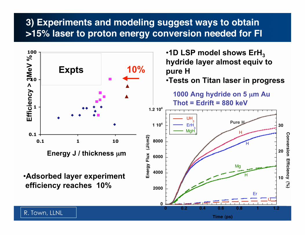
•Adsorbed layer experiment
efficiency reaches 10%
10%
•1D LSP model shows ErH3
hydride layer almost equiv to
pure H
•Tests on Titan laser in progress
1000 Ang hydride on 5 µm Au
Thot = Edrift = 880 keV
Expts
3) Experiments and modeling suggest ways to obtain>15% laser to proton energy conversion needed for FI
R. Town, LLNL

4) Shock compressed foam simulates FI cone tip
Foam
Cu
Au
60
30
00 Tem
p,
eV
, g
/cc
6
3
0
depth, mm
0.150.160.170.18
• Replace sphere and cone with flat plates
• Long pulse accelerates Al/Cu flyer plate
• Compresses foam to ~1 g/cc
• Shock wave penetrates Au foil on opposite side
• Electrons generated in Au cross the Au/interfaceand are counted in Cu
J. Pasley, UCSD
Experiments underway
at Titan (LLNL)

5) Comparing simulations to expt
Objective is to perform anexperiment that can beaccurately modeled
• Nail target size limited bypointing accuracy andbeam size
• Must account formodification by prepulse
• Heating and current flowcan be compared tosimulations
20060809s2 XUV - 256 eV
100 µm dia head
20 µm dia wire
500 J, 1 ps
1014 w/cm2 400 ps
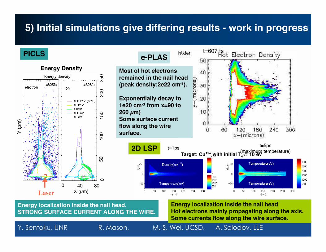
5) Initial simulations give differing results - work in progress
Range: ± 10MGLaser
Energy Density
Y (
µm)
X (µm)0 40 80
050
100
150
200
250
PICLS e-PLAS
2D LSP
Energy localization inside the nail headHot electrons mainly propagating along the axis.Some currents flow along the wire surface.
Energy localization inside the nail head.STRONG SURFACE CURRENT ALONG THE WIRE.
Target: Cu15+ with initial Te@ 10 eV
t=607 fs
Most of hot electronsremained in the nail head(peak density:2e22 cm-3).
Exponentially decay to1e20 cm-3 from x=90 to260 µm)Some surface currentflow along the wiresurface.
Y. Sentoku, UNR R. Mason, M.-S. Wei, UCSD, A. Solodov, LLE
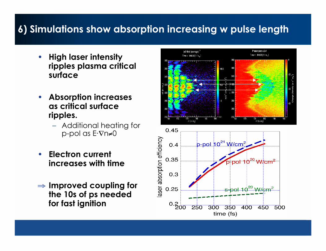
6) Simulations show absorption increasing w pulse length
• High laser intensityripples plasma criticalsurface
• Absorption increasesas critical surfaceripples.
– Additional heating forp-pol as E· n 0
• Electron currentincreases with time
Improved coupling forthe 10s of ps neededfor fast ignition
Summary
• Multi-institutional research team has been formed and is working well
• “ignition” approaches include– Electron driven
– Proton driven
– High velocity impact
– shock
• Present experiments are limited– Current facilities allow generation of small hot plasmas
– New diagnostics are being developed
• Research is focused on evaluation of “component” phenomena withcombined experiments and simulation
• An integrated evaluation of FI awaits facilities nearing completion– Integrated code packages
– Integrated experiments
– Target fab