Status of ALOS-2 PALSAR-2 calibration and validation and...
25
Status of ALOS-2 PALSAR-2 calibration and validation and its follow-on L-band SAR Takeshi Motohka 1 , Osamu Isoguchi 2 , Masanori Sakashita 2 , Masanobu Shimada 1,3 , and Shinichi Suzuki 1 1. Japan Aerospace Exploration Agency (JAXA) 2. RESTEC 3. Tokyo Denki University CEOS SAR CalVal Workshop, JPL Pasadena Nov. 7, 2017 1
Transcript of Status of ALOS-2 PALSAR-2 calibration and validation and...

Status of ALOS-2 PALSAR-2 calibration and validation
and its follow-on L-band SAR
�Takeshi Motohka1, Osamu Isoguchi2, Masanori Sakashita2, Masanobu Shimada1,3, and Shinichi Suzuki1
1. Japan Aerospace Exploration Agency (JAXA)2. RESTEC
3. Tokyo Denki University
CEOS SAR CalVal Workshop, JPL PasadenaNov. 7, 2017
1

Mission sensor
• PALSAR-2 (L-band SAR)• SPAISE2 (AIS)
Launch May 24, 2014H-IIA launch vehicle
Lifetime 5 years (target: 7 years)
Orbit Sun-synchronous,628 km altitude,14 days revisit,Orbit control: ≦ +/- 500 m
Local suntime
12:00�15 min (descending)24:00�15 min(ascending)
Mission data transmission
X-band:800 Mbps (16 QAM),200/400 Mbps (QPSK)
Advanced Land Observing Satellite-2 (ALOS-2)
PALSAR-2(Phased Array type L-band Synthetic Aperture Radar 2)
PALSAR-2 antenna X-band downlink antenna
Solar Arrays
XY
Z
2

2014 2015 2016 2017 2018 2019 2020 2021
Launch
Initial C/O
Initial Cal-Val
Product release
Mission operation (5 years) Post-mission operation
ALOS-3(Optical)
May 24
ALOS-2 operation phase
3
ALOS-2(L-SAR)
ALOS-4(L-SAR) Development
Development

Items Results
Geometry (RMSE)
[Stripmap and Spotlight] 5.34 m (L1.1) / 6.73 m (L2.1) [ScanSAR] 60.77 m (L1.1) / 29.93 m (L2.1)
Radiometry RCS accuracy (1σ)0.56 dB (corner reflectors)0.77 dB (Amazonian forests)
Polarimetry
VV-HH amplitude ratio 1.004 (σ=0.012)
VV-HH phase difference
-1.19 deg (σ=4.42)
Cross talk[HV/HH] -39.4 dB (σ=9.1)[VH/VV] -39.1 dB (σ=11.0)
PALSAR-2 cal/val status
Validation results of standard products (as of Jul. 2017)
4
• On-board internal calibration has been performed every 3 months.• Product quality of major observation modes has been evaluated regularly
using SAR data over calibration sites.• Standard product processing software was updated in March 2017.

5
Cal/Val sites in Japan
SAR
��
Antenna
< 1.5 m
ARC/GCCRSignal receiver
l Tomakomai, Hokkaido … 4 permanent CRs
l Kanto region (around Tokyo) … temporal (30 times/year)
CR, ARC/GC, receiver
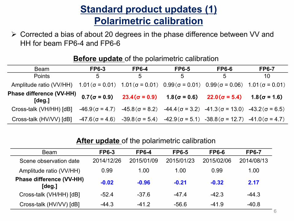
Beam FP6-3 FP6-4 FP6-5 FP6-6 FP6-7Points 5 5 5 5 10
Amplitude ratio (VV/HH) 1.01�σ = 0.01� 1.01�σ = 0.01� 0.99�σ = 0.01� 0.99�σ = 0.06� 1.01�σ = 0.01�Phase difference (VV-HH)
[deg.] 0.7�σ = 0.9� 23.4�σ = 0.9� 1.8�σ = 0.6� 22.0�σ = 5.4� 1.8�σ = 1.6�
Cross-talk (VH/HH) [dB] -46.9�σ = 4.7� -45.8�σ = 8.2� -44.4�σ = 3.2� -41.3�σ = 13.0� -43.2�σ = 6.5�
Cross-talk (HV/VV) [dB] -47.6�σ = 4.6� -39.8�σ = 5.4� -42.9�σ = 5.1� -38.8�σ = 12.7� -41.0�σ = 4.7�
Before update of the polarimetric calibration
Ø Corrected a bias of about 20 degrees in the phase difference between VV and HH for beam FP6-4 and FP6-6
Beam FP6-3 FP6-4 FP6-5 FP6-6 FP6-7Scene observation date 2014/12/26 2015/01/09 2015/01/23 2015/02/06 2014/08/13
Amplitude ratio (VV/HH) 0.99 1.00 1.00 0.99 1.00Phase difference (VV-HH)
[deg.] -0.02 -0.96 -0.21 -0.32 2.17
Cross-talk (VH/HH) [dB] -52.4 -37.6 -47.4 -42.3 -44.3
Cross-talk (HV/VV) [dB] -44.3 -41.2 -56.6 -41.9 -40.8
After update of the polarimetric calibration
6
Standard product updates (1) Polarimetric calibration

Mode Evaluation result Correction value[dB]Points Mean [dB] SD [dB]
Spotlight 9 -81.058 0.729 +1.942 U2-6 29 -81.615 0.446 +1.385 U2-7 18 -81.237 0.812 +1.763 U2-8 14 -81.590 0.389 +1.411 U2-9 15 -81.668 0.329 +1.332 FP6-3 6 -81.040 0.369 +1.960 FP6-4 8 -81.733 0.572 +1.267 FP6-5 4 -82.770 0.495 +0.231 FP6-6 5 -82.477 0.851 +0.523 FP6-7 7 -80.812 0.404 +2.188 F2-5 23 -82.374 0.337 +0.626 F2-6 12 -82.351 0.424 +0.649 F2-7 7 -81.911 0.226 +1.089
Ø Elevation antenna pattern correction and CF was updated in March 28, 2017.
Evaluation results of the calibration factor (CF) of previous versionand correction values for update version
7
Standard product updates (2) Radiometric calibration factor (CF)

Evaluation results of radiometric calibration factor (CF)
Number of CR observations
FBD mode(10m stripmap)
HBQ mode(6m full-pol)
UBS mode(3m stripmap)
8
• Corner reflector (CR) data• Observation date: Jul. 2014�Feb. 2017
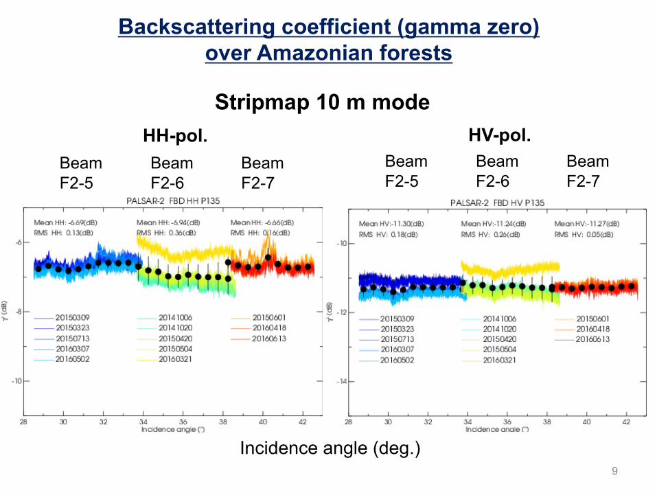
Backscattering coefficient (gamma zero) over Amazonian forests
Incidence angle (deg.)
BeamF2-7
BeamF2-6
BeamF2-5
BeamF2-7
BeamF2-6
BeamF2-5
HH-pol. HV-pol.
9
Stripmap 10 m mode
10
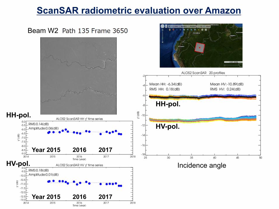
ScanSAR radiometric evaluation over Amazon
Beam W2
Year 2015 2016 2017
Year 2015 2016 2017
HH-pol.
HV-pol.
HH-pol.
HV-pol.
Incidence angle
11
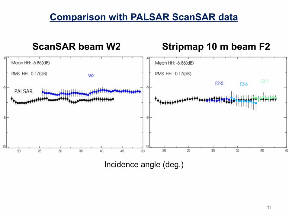
Comparison with PALSAR ScanSAR data
ScanSAR beam W2 Stripmap 10 m beam F2
Incidence angle (deg.)

12
Slant range error (m) from CR data
Δs: path delay due to TEC [m]K: refractive constant = 40.28 [m3/s2]TEC: Total electron content [TECU]f: center frequeny [Hz]α: off-nadir angle [deg.]
Ionospheric effects on geometric error
Range delay estimated by TEC N=180
* TEC data from BERN university
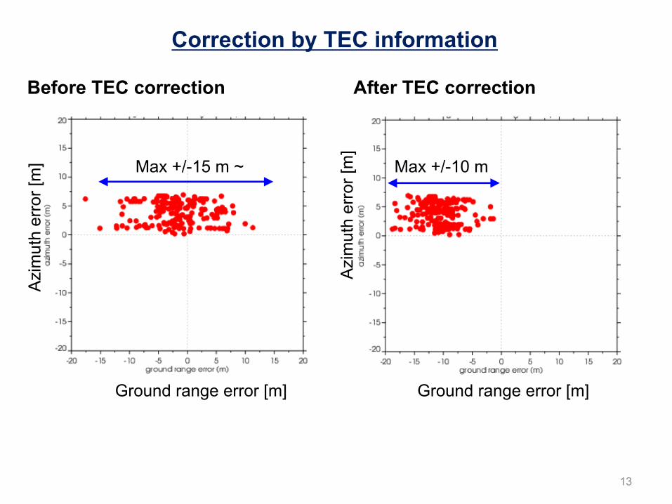
13
Before TEC correction After TEC correction
Azim
uth
erro
r [m
]
Ground range error [m] Ground range error [m]
Azim
uth
erro
r [m
]
Max +/-15 m ~ Max +/-10 m
Correction by TEC information
14
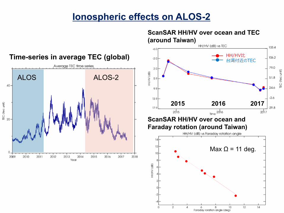
ALOS ALOS-2
Ionospheric effects on ALOS-2
Time-series in average TEC (global)
ScanSAR HH/HV over ocean and TEC (around Taiwan)
ScanSAR HH/HV over ocean and Faraday rotation (around Taiwan)
2015 2016 2017
Max Ω = 11 deg.

ALOS-4 (Advanced Land Observing Satellite-4)

Continuation and enhancement of the ALOS-2 missions and new applications
1. Land deformation and subsidence monitoring• Detecting anomalies at an earlier stage by increasing observation frequency
2. Disaster monitoring• Keeping observation capability at night and at bad-weather conditions• Wide-area coverage for large earthquakes and multiple events
3. Other continuous missions and new applications • Environmental monitoring: time-series change of forests, wetlands, ice
sheets, etc.• Ocean: ship detection, sea ice drift monitoring, etc.• Agriculture and natural resources• Inspection of increasing aging infrastructures (dams, airports, etc.) using
time-series interferometry
Mission objectives of ALOS-4

High spatial resolution(1~10 m)
High observation frequency(> 20 times/year)
Wide area coverage(> 200 km swath)
Repeat-pass orbit and the same orbit as ALOS-2
Wide observable range and high-speed data transmission
Polarimetric observation
Long time continuous operation
System requirements
User needs to system requirements
Disaster monitoring• Observation at night time and bad
weather condition• Quick initial response
Continuation from ALOS-2 and new applications
• Infrastructure (dams, etc.)• Forest and wetland• Ship detection • Agriculture• Sea ice and ice sheet• Natural resources
Land deformation and subsidence
• High observation frequency and spatial resolution
• Basemap observation over Japan
Main user needs

Launch JFY 2020H3 launch vehicle
Orbit
Same orbit as ALOS-2Sun-synchronous sub-recurrent orbitAltitude: 628 kmInclination angle: 97.9 degreeLocal sun time at descending: 12:00 ±15 min. Revisit time: 14 day (15-3/14 rev/day)
Lifetime 7 years
Satellite Mass approx. 3 tons
Downlink 3.6 Gbps/1.8 Gbps (Ka-band)
Mission Instruments
- PALSAR-3 (Phased Array type L-band Synthetic Aperture Radar-3)
- SPAISE3 (SPace based AIS Experiment 3)
Prime contractor Mitsubishi Electric Corporation
PALSAR-3antenna
ALOS-4 System characteristics
�
�
�
Ka-band DT antenna
SPAISE3antenna
Solar array paddle

Ø Expanding swath width without decreasing the resolution and image quality of PALSAR-2 by using the digital beam forming (DBF).
Ø To guarantee the continuity of ALOS-2 applications, PALSAR-3 would inherit the major function and performance (NESZ, S/A, etc.) of PALSAR-2
Characteristics of PALSAR-3
ALOS-4 ALOS-2
Stripmap(res. 3/6/10 m)
100-200 km 30-70 km
ScanSAR(res. 25m*)
700 km 350-490 km
Spotlight(res. 1 x 3 m)
35km�35km 25km�25km
Swath width 100-200 km*single look
Input: 6 ch. in rangeOutput: max. 4 beams

ALOS2006-2011
ALOS-22014-
ALOS-42020-
Antenna size 3 m�9 m 3 m�10 m 3.6 m�10 m
Number of T/Rmodule 80 (Si) 180 (GaN) 232 (GaN)
Transmit power 2,000 W 6,120 W 7,888 W
Receive beam Single beam Dual beam (azimuth)
DBF (range) + Dual beam (azimuth)
Ionosphericcorrection N/A N/A Split-band mode
(28 + 10 MHz)Pointing Right Right and Left Right and Left
Orbit control < +/- 2.5 km (at equator)
< +/- 500 m(all latitude)
< +/- 500 m (all latitude)Laser reflector for
absolute calibration
Data recorder 90 GB 128 GB 1 TB
Data transmission 120 / 240 Mbps 800 Mbps 3.6 / 1.8 Gbps
System improvement from ALOS/ALOS-2

Summary
Ø PALSAR-2 calibration and validation are conducted regularly. ALOS-2 keeps good performance over 3 years and a lot of L-band SAR data have been accumulated.
Ø JAXA has started the development of ALOS-4 as a follow-on L-band SAR satellite of ALOS-2. The ALOS-4 project is now in phase B (Preliminary design phase).
JAXA Joint PI Meeting (including ALOS-2 PI meeting)Date: Jan. 22 (Mon) - 25 (Thu), 2018Place: Tokyo, JapanAbstract deadline� Nov. 17 (Fri), 2017
http://suzaku.eorc.jaxa.jp/meeting/jointpi2017/index_en.htmlorPlease check EORC ALOS-2 website

22
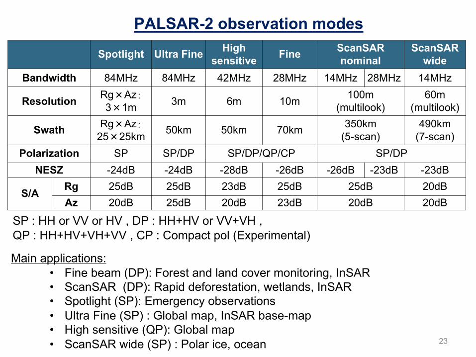
Spotlight Ultra Fine Highsensitive Fine ScanSAR
nominalScanSAR
wideBandwidth 84MHz 84MHz 42MHz 28MHz 14MHz 28MHz 14MHz
Resolution Rg�Az�3�1m 3m 6m 10m
100m(multilook)
60m(multilook)
Swath Rg�Az�25�25km
50km 50km 70km 350km(5-scan)
490km(7-scan)
Polarization SP SP/DP SP/DP/QP/CP SP/DP
NESZ -24dB -24dB -28dB -26dB -26dB -23dB -23dB
S/A Rg 25dB 25dB 23dB 25dB 25dB 20dBAz 20dB 25dB 20dB 23dB 20dB 20dB
Main applications:• Fine beam (DP): Forest and land cover monitoring, InSAR• ScanSAR (DP): Rapid deforestation, wetlands, InSAR• Spotlight (SP): Emergency observations• Ultra Fine (SP) : Global map, InSAR base-map• High sensitive (QP): Global map• ScanSAR wide (SP) : Polar ice, ocean
SP : HH or VV or HV , DP : HH+HV or VV+VH , QP : HH+HV+VH+VV , CP : Compact pol (Experimental)
PALSAR-2 observation modes
23

ALOS-2 calibration & validation team sites
24

Backscattering coefficient (gamma zero) at Amazonian forests
Incidence angle (deg.)
BeamU2-9
BeamU2-8
BeamU2-7HH-pol.
25
BeamU2-6
Stripmap 3 m mode