Stationary Armor Target - United States Army
13
RANGE AND TRAINING LAND PROGRAM – MANDATORY CENTER OF EXPERTISE U.S. ARMY ENGINEERING AND SUPPORT CENTER, HUNTSVILLE HUNTSVILLE, ALABAMA 256-895-1534 EMAIL RTLP Stationary Armor Target (SAT)
Transcript of Stationary Armor Target - United States Army
RANGE AND TRAINING LAND PROGRAM – MANDATORY CENTER OF EXPERTISE
U.S. ARMY ENGINEERING AND SUPPORT CENTER, HUNTSVILLE
HUNTSVILLE, ALABAMA
256-895-1534
EMAIL RTLP
Stationary Armor Target
(SAT)
BUILDING STRONG® 1
Sta
tio
na
ry A
rmo
r Ta
rge
t– A
ugu
st
20
17
RTLP
-MC
X R
an
ge
De
sig
n G
uid
e
General
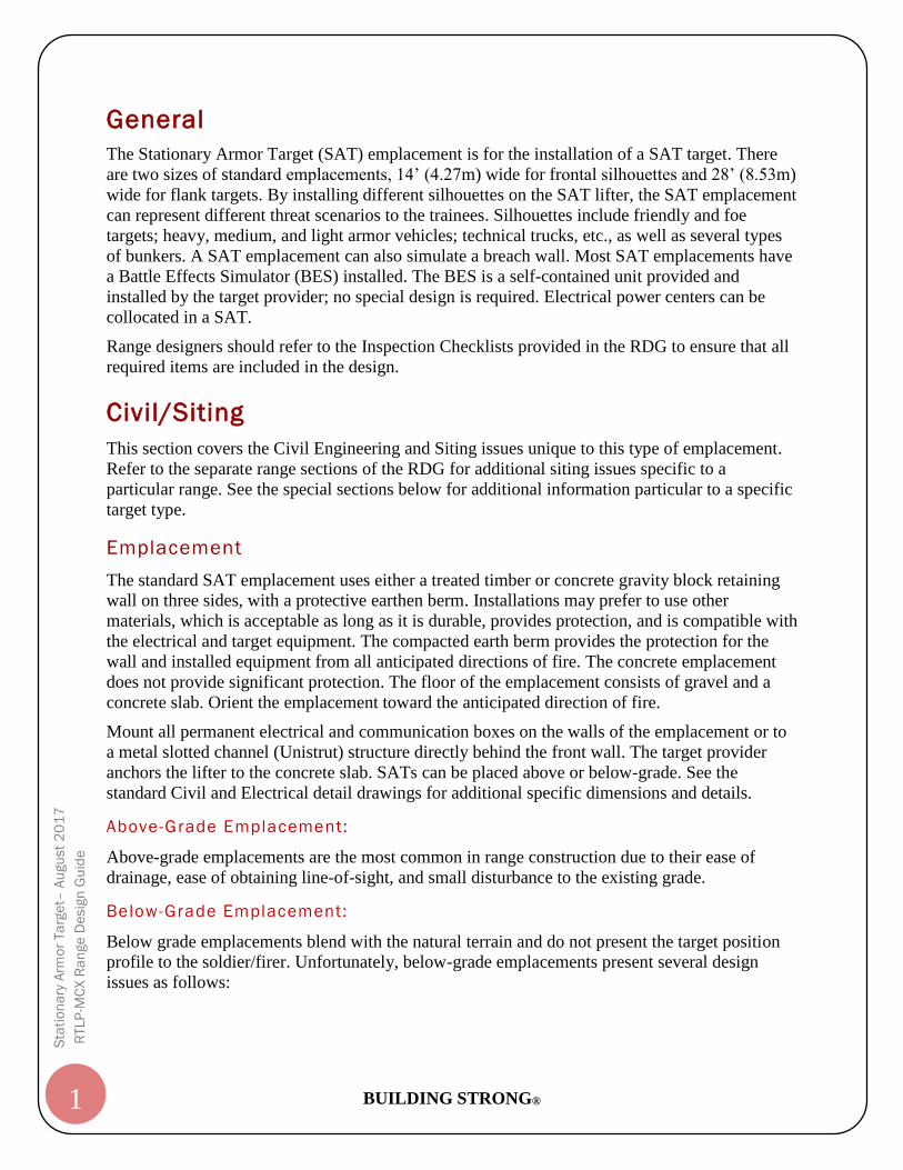
The Stationary Armor Target (SAT) emplacement is for the installation of a SAT target. There
are two sizes of standard emplacements, 14’ (4.27m) wide for frontal silhouettes and 28’ (8.53m)
wide for flank targets. By installing different silhouettes on the SAT lifter, the SAT emplacement
can represent different threat scenarios to the trainees. Silhouettes include friendly and foe
targets; heavy, medium, and light armor vehicles; technical trucks, etc., as well as several types
of bunkers. A SAT emplacement can also simulate a breach wall. Most SAT emplacements have
a Battle Effects Simulator (BES) installed. The BES is a self-contained unit provided and
installed by the target provider; no special design is required. Electrical power centers can be
collocated in a SAT.
Range designers should refer to the Inspection Checklists provided in the RDG to ensure that all
required items are included in the design.
Civil/Siting
This section covers the Civil Engineering and Siting issues unique to this type of emplacement.
Refer to the separate range sections of the RDG for additional siting issues specific to a
particular range. See the special sections below for additional information particular to a specific
target type.
Emplacement
The standard SAT emplacement uses either a treated timber or concrete gravity block retaining
wall on three sides, with a protective earthen berm. Installations may prefer to use other
materials, which is acceptable as long as it is durable, provides protection, and is compatible with
the electrical and target equipment. The compacted earth berm provides the protection for the
wall and installed equipment from all anticipated directions of fire. The concrete emplacement
does not provide significant protection. The floor of the emplacement consists of gravel and a
concrete slab. Orient the emplacement toward the anticipated direction of fire.
Mount all permanent electrical and communication boxes on the walls of the emplacement or to
a metal slotted channel (Unistrut) structure directly behind the front wall. The target provider
anchors the lifter to the concrete slab. SATs can be placed above or below-grade. See the
standard Civil and Electrical detail drawings for additional specific dimensions and details.
Above-Grade Emplacement:
Above-grade emplacements are the most common in range construction due to their ease of
drainage, ease of obtaining line-of-sight, and small disturbance to the existing grade.
Below-Grade Emplacement:
Below grade emplacements blend with the natural terrain and do not present the target position
profile to the soldier/firer. Unfortunately, below-grade emplacements present several design
issues as follows:
BUILDING STRONG® 2
Sta
tio
na
ry A
rmo
r Ta
rge
t– A
ugu
st
20
17
RTLP
-MC
X R
an
ge
De
sig
n G
uid
e
Drainage:
Positive drainage is harder to achieve on a below grade emplacement. Floor drains are
problematic in that they require a lower elevation nearby for a daylight drain and tend to
clog. Drainage swales increase excavation requirements.
Unexploded Ordnance (UXO):
UXO disturbance potential increases with the depth of excavation. While an above-grade
emplacement might only require disturbing the surface to 150mm (6in) below natural
grade, below-grade emplacements often require excavation of 1m (3ft) or more. For
medium and high-risk areas, normally a subsurface clearance to a depth of one foot
below the construction footprint is required.
Line-of-Sight:
Line-of-sight between the firing position and the target emplacement may not be possible
using the natural terrain.
Other debris:
Below-grade emplacements also tend to gather more sand, snow, dirt, trash, and any
windblown objects, which can cause maintenance problems.
The designer should discuss with the installation whether they desire above or below-grade SAT
emplacements, while ensuring that the installation understands the design issues and costs
associated with either choice.
Drainage
Ensuring proper drainage is critical in the design and construction of target emplacements. Even
though the electrical and target equipment is designed for outdoor installation, many of the issues
with range targetry can be avoided with proper emplacement drainage. The ground should slope
away from the emplacement whenever possible; add swales as necessary to ensure positive
drainage. The floor of the emplacement must slope to the rear. Special care is required in the use
of floor and trench drains, as they tend to clog easily and freeze in some climates. Ensure proper
compaction under the emplacement to avoid differential settlement. Drainage is especially
critical on newly constructed ranges before vegetation is fully established.
Target Clearance
Provide a clear unobstructed area behind the emplacement to allow space for the target in the
down position; a minimum of 6.4m (21ft) measured from the face of the emplacement wall.
Configuration
The Civil Details and Electrical Details in the Appendix of this document show the standard
SAT emplacement configuration. The emplacement design supports the ballistic characteristics
of armor, low-hover helicopters and anti-armor systems. The emplacement does not provide
protection from helicopter running and diving fire.
BUILDING STRONG® 3
Sta
tio
na
ry A
rmo
r Ta
rge
t– A
ugu
st
20
17
RTLP
-MC
X R
an
ge
De
sig
n G
uid
e
Wall Height
The front wall and berm must be high enough to protect the targetry equipment while still
allowing target visibility from the firing position. The minimum front wall height is 1067mm (3ft
6in), 1372mm (4ft 6in) for aerial gunnery. The height has been coordinated within the program
as the minimum that hides both the electrical equipment and the targetry based on a relatively
flat angle of fire from the shooter to the target, generally +/- 2 degrees.
Angle of Fire
The angle of fire (AOF) from the gun barrel to the target is a critical parameter on a range that
affects the functionality in a number of ways. Certain range and weapon types have a limit on the
allowable angle of fire, e.g. a Known Distance range limits the AOF to +/- 2 degrees. Refer to
the installation trainers, applicable training manuals, and the RDG section for specific range
types for additional information and guidance. In addition, the amount of the target that is visible
to shooters can affect the ability to qualify, i.e. it is harder to hit the target when only half of it is
visible. Finally, rounds can hit and damage targetry and electrical equipment on higher angles of
fire.
The standard SAT emplacement with a 42-inch front wall and a 2-percent slope on the berm
provides adequate protection for AOF of +/- 2 degrees. Greater angles require special design
consideration. Higher negative angles may require increasing the front wall height, adjusting the
slope of the berm to match the AOF, or some other method. Theoretically, the minimum wall
height hides the electrical equipment, including the target arms and clamps, up to a -10o AOF,
higher with the aviation wall height. In situations with a positive AOF, greater than 2 degrees,
the berm itself begins to hide the target. Adjustments to the berm slope may be necessary.
On ranges where target engagement is from multiple points, the designer must coordinate closely
with the installation and the targetry provider to determine the correct front wall height. The
emplacement protection is also critical for aviation gunnery.
Wall Design
Typical retaining walls are designed using concrete gravity block or wood timbers and steel
piles. Design the walls so that the top section is replaceable in case of damage. Filter fabric is
normally required. The design of the SAT walls must take in consideration the stability of the
wall, including site-specific geotechnical conditions. The design must include overturning,
sliding, and settling.
Berm Criteria
The Target Protection Design Curves, in the Target Protection Section of the RDG, provide the
recommended thickness for emplacement protective berms. The curve thicknesses provide
protection from many bullet impacts; the amount of soil needed to stop a single round is
significantly less. The berm must protect the emplacement from all anticipated directions of fire,
but is thickest in the expected direction of fire. Use thinner berms to protect the emplacement
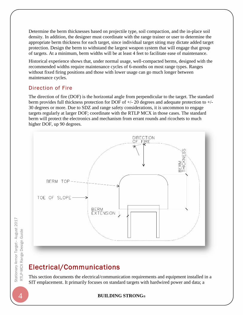
from occasional directions of fire and ricochets. The standard berm extensions are ¼ of the berm
thickness; see figure below.
BUILDING STRONG® 4
Sta
tio
na
ry A
rmo
r Ta
rge
t– A
ugu
st
20
17
RTLP
-MC
X R
an
ge
De
sig
n G
uid
e
Determine the berm thicknesses based on projectile type, soil compaction, and the in-place soil
density. In addition, the designer must coordinate with the range trainer or user to determine the
appropriate berm thickness for each target, since individual target siting may dictate added target
protection. Design the berm to withstand the largest weapon system that will engage that group
of targets. At a minimum, berm widths will be at least 4 feet to facilitate ease of maintenance.
Historical experience shows that, under normal usage, well-compacted berms, designed with the
recommended widths require maintenance cycles of 6-months on most range types. Ranges
without fixed firing positions and those with lower usage can go much longer between
maintenance cycles.
Direction of Fire
The direction of fire (DOF) is the horizontal angle from perpendicular to the target. The standard
berm provides full thickness protection for DOF of +/- 20 degrees and adequate protection to +/-
30 degrees or more. Due to SDZ and range safety considerations, it is uncommon to engage
targets regularly at larger DOF; coordinate with the RTLP MCX in those cases. The standard
berm will protect the electronics and mechanism from errant rounds and ricochets to much
higher DOF, up 90 degrees.
Electrical/Communications
This section documents the electrical/communication requirements and equipment installed in a
SIT emplacement. It primarily focuses on standard targets with hardwired power and data; a
BUILDING STRONG® 5
Sta
tio
na
ry A
rmo
r Ta
rge
t– A
ugu
st
20
17
RTLP
-MC
X R
an
ge
De
sig
n G
uid
e
paragraph below has information on battery-operated targets. The Downrange Power & Data
Distribution Sections of the RDG describe requirements for downrange power distribution, data
networks, transformers, trenching, etc. Use those sections in addition this document to design a
complete range. In addition, since some range types have power and data requirements that differ
from the standard, refer to the specific range section for details.
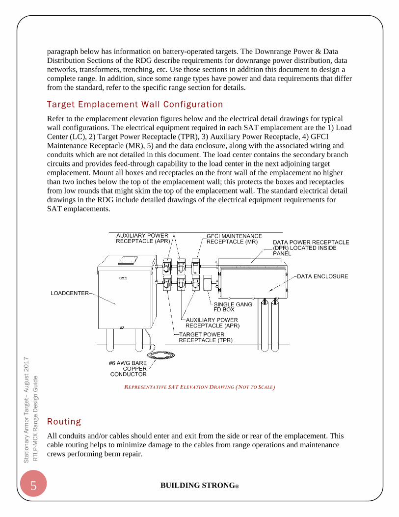
Target Emplacement Wall Configuration
Refer to the emplacement elevation figures below and the electrical detail drawings for typical
wall configurations. The electrical equipment required in each SAT emplacement are the 1) Load
Center (LC), 2) Target Power Receptacle (TPR), 3) Auxiliary Power Receptacle, 4) GFCI
Maintenance Receptacle (MR), 5) and the data enclosure, along with the associated wiring and
conduits which are not detailed in this document. The load center contains the secondary branch
circuits and provides feed-through capability to the load center in the next adjoining target
emplacement. Mount all boxes and receptacles on the front wall of the emplacement no higher
than two inches below the top of the emplacement wall; this protects the boxes and receptacles
from low rounds that might skim the top of the emplacement wall. The standard electrical detail
drawings in the RDG include detailed drawings of the electrical equipment requirements for
SAT emplacements.
REPRESENTATIVE SAT ELEVATION DRAWING (NOT TO SCALE)
Routing
All conduits and/or cables should enter and exit from the side or rear of the emplacement. This
cable routing helps to minimize damage to the cables from range operations and maintenance
crews performing berm repair.
BUILDING STRONG® 6
Sta
tio
na
ry A
rmo
r Ta
rge
t– A
ugu
st
20
17
RTLP
-MC
X R
an
ge
De
sig
n G
uid
e
Grounding
Grounding is required for safety at each downrange emplacement or equipment location. A
19mm (3/4in) by 3,050mm (10ft) copper-clad steel ground rod will be driven to a depth of
305mm (1ft) below finished grade at each emplacement or equipment location. The MTDP/TDP
and load center equipment will be connected to the emplacement’s single ground rod with a #6
AWG bare copper conductor and exothermically welded connections. All data cable armor or
shields must be bonded to the ground bar in the TDP. The design will leave a 3048mm (10ft) coil
of #6 AWG bare copper that will be used to ground the target mechanism.
Surge Suppression
Provide surge protective devices (SPD) in the load center of all target emplacements. The surge
suppression for the data communication cables will be provided by the target vendor during the
installation of targets.
Conduit and Cable Fittings
All penetrations into the MTDP or TDP must be made with fittings approved for use with a
NEMA 4, 4X or 6P enclosure. Non-compliance with this requirement will result in
equipment failure. The standard electrical detail drawings in the RDG illustrate the preferred
sealing method. Foam filled conduits are not acceptable. The SIT load center only requires a
NEMA 3R rated enclosure. Provide fittings approved for use with a NEMA 3R enclosure for
connection to the load center.
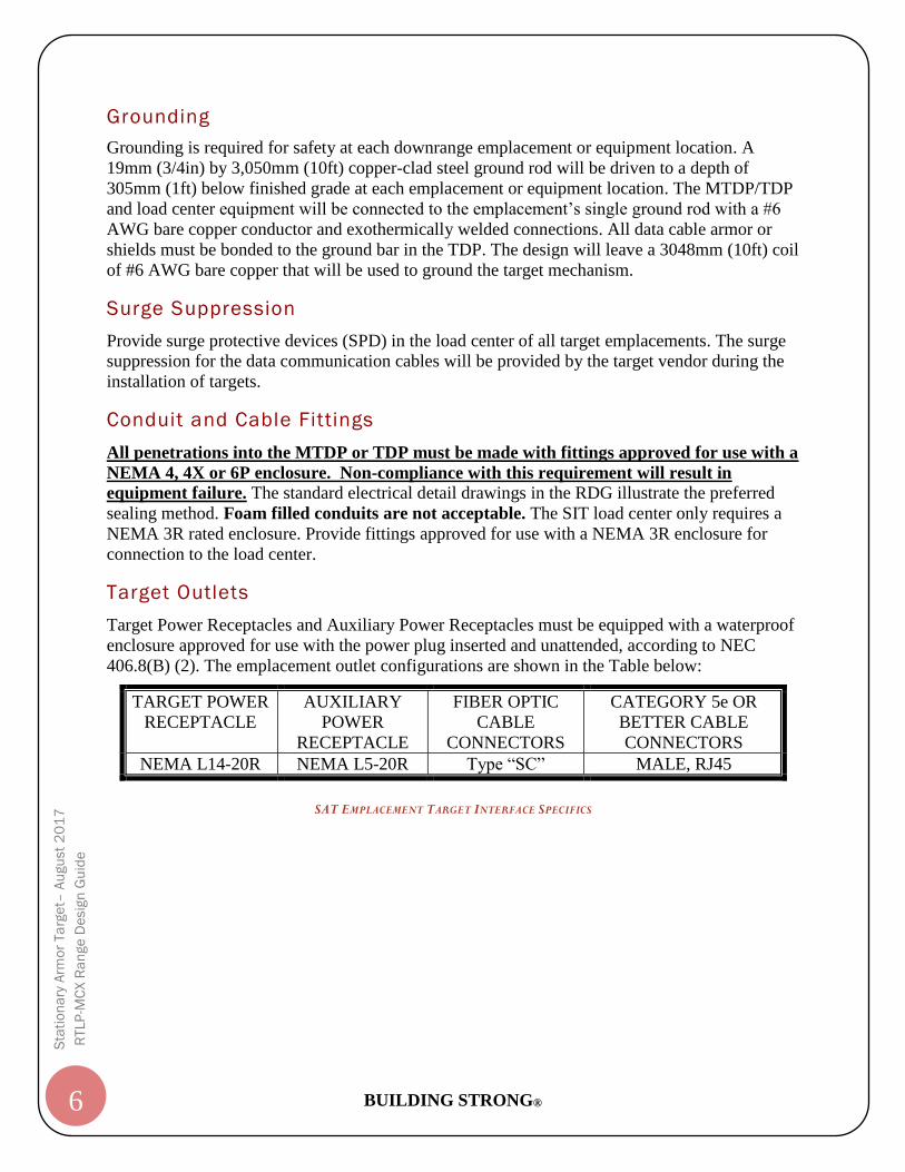
Target Outlets
Target Power Receptacles and Auxiliary Power Receptacles must be equipped with a waterproof
enclosure approved for use with the power plug inserted and unattended, according to NEC
406.8(B) (2). The emplacement outlet configurations are shown in the Table below:
SAT EMPLACEMENT TARGET INTERFACE SPECIFICS
TARGET POWER
RECEPTACLE
AUXILIARY
POWER
RECEPTACLE
FIBER OPTIC
CABLE
CONNECTORS
CATEGORY 5e OR
BETTER CABLE
CONNECTORS
NEMA L14-20R NEMA L5-20R Type “SC” MALE, RJ45
BUILDING STRONG® 7
Sta
tio
na
ry A
rmo
r Ta
rge
t– A
ugu
st
20
17
RTLP
-MC
X R
an
ge
De
sig
n G
uid
e
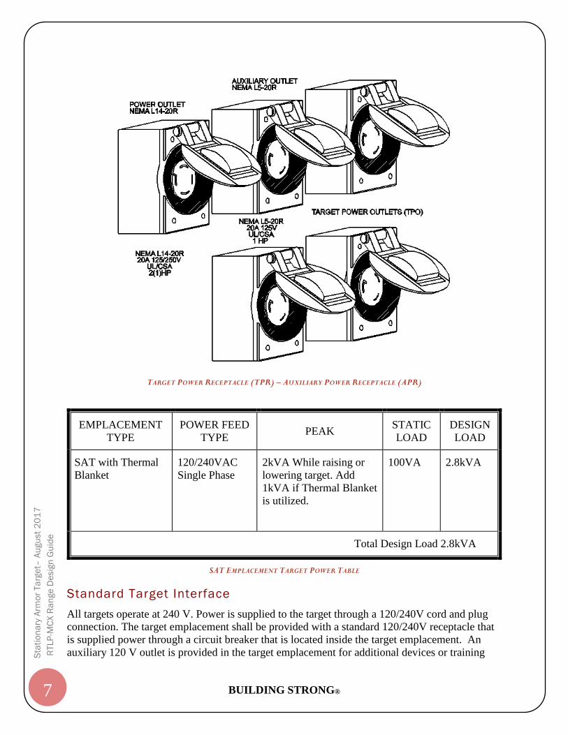
TARGET POWER RECEPTACLE (TPR) – AUXILIARY POWER RECEPTACLE (APR)
SAT EMPLACEMENT TARGET POWER TABLE
Standard Target Interface
All targets operate at 240 V. Power is supplied to the target through a 120/240V cord and plug
connection. The target emplacement shall be provided with a standard 120/240V receptacle that
is supplied power through a circuit breaker that is located inside the target emplacement. An
auxiliary 120 V outlet is provided in the target emplacement for additional devices or training
EMPLACEMENT
TYPE
POWER FEED
TYPE PEAK
STATIC
LOAD
DESIGN
LOAD
SAT with Thermal
Blanket
120/240VAC
Single Phase
2kVA While raising or
lowering target. Add
1kVA if Thermal Blanket
is utilized.
100VA
2.8kVA
Total Design Load 2.8kVA
BUILDING STRONG® 8
Sta
tio
na
ry A
rmo
r Ta
rge
t– A
ugu
st
20
17
RTLP
-MC
X R
an
ge
De
sig
n G
uid
e
aids that may be added to the target mechanism. Thermal blankets are the most common devices
that are added to the target mechanisms that utilize this power outlet. The specific components
used to supply power to the target mechanisms installed inside each target emplacement is fully
defined in the remaining sections.
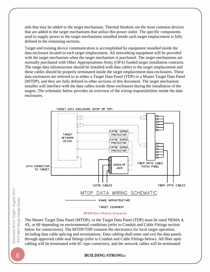
Target and training device communication is accomplished by equipment installed inside the
data enclosure located in each target emplacement. All networking equipment will be provided
with the target mechanism when the target mechanism is purchased. The target mechanisms are
normally purchased with Other Appropriations-Army (OPA) funded target installation contracts.
The range data infrastructure should be installed with data cables to the target emplacement and
these cables should be properly terminated inside the target emplacement data enclosures. These
data enclosures are referred to as either a Target Data Panel (TDP) or a Master Target Data Panel
(MTDP), and they are fully defined in other sections of this document. The target mechanism
installer will interface with the data cables inside these enclosures during the installation of the
targets. The schematic below provides an overview of the wiring responsibilities inside the data
enclosures.
MTDP DATA WIRING SCHEMATIC
The Master Target Data Panel (MTDP), or the Target Data Panel (TDP) must be rated NEMA 4,
4X, or 6P depending on environmental conditions (refer to Conduit and Cable Fittings section
below for connections). The MTDP/TDP contains the electronics for local target operation,
including data cable splicing and terminations. Data cabling shall enter and exit the data panels
through approved cable seal fittings (refer to Conduit and Cable Fittings below). All fiber optic
cabling will be terminated with SC type connectors, and the network cables will be terminated
BUILDING STRONG® 9
Sta
tio
na
ry A
rmo
r Ta
rge
t– A
ugu
st
20
17
RTLP
-MC
X R
an
ge
De
sig
n G
uid
e
with CAT 5e or better rated RJ45 connectors. The MTDP and TDP provides space for Other
Appropriations-Army (OPA) funded equipment which may include the fiber optic jumpers,
switch/media converter, target data outlet, and network cables. The OPA equipment is installed
by others and not the MILCON contractor. The designer must ensure the dimensions of the data
panel are consistent with those dimensions stated on the detail plans for the MTDP and TDP
equipment. A 120v AC power outlet is provided in the TDP for “Use by Others”. The TDP and
the GFCI maintenance receptacle may utilize the same power circuit, but the TDP equipment
must be wired ahead of the maintenance to ensure no nuisance tripping occurs. Reference the
Electrical and Civil Details in the directory of the Range Design Guide for more information
pertaining to the MTDP, TDP and their mounting requirements.
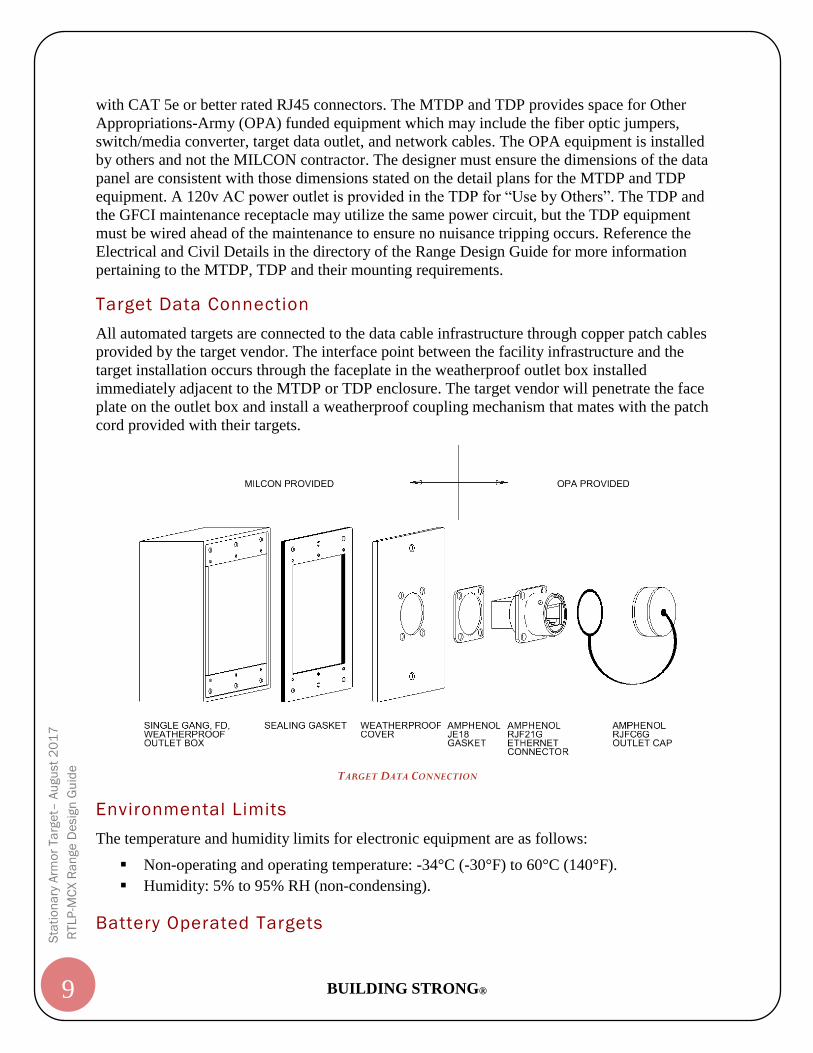
Target Data Connection
All automated targets are connected to the data cable infrastructure through copper patch cables
provided by the target vendor. The interface point between the facility infrastructure and the
target installation occurs through the faceplate in the weatherproof outlet box installed
immediately adjacent to the MTDP or TDP enclosure. The target vendor will penetrate the face
plate on the outlet box and install a weatherproof coupling mechanism that mates with the patch
cord provided with their targets.
TARGET DATA CONNECTION
Environmental Limits
The temperature and humidity limits for electronic equipment are as follows:
Non-operating and operating temperature: -34°C (-30°F) to 60°C (140°F).
Humidity: 5% to 95% RH (non-condensing).
Battery Operated Targets
BUILDING STRONG® 10
Sta
tio
na
ry A
rmo
r Ta
rge
t– A
ugu
st
20
17
RTLP
-MC
X R
an
ge
De
sig
n G
uid
e
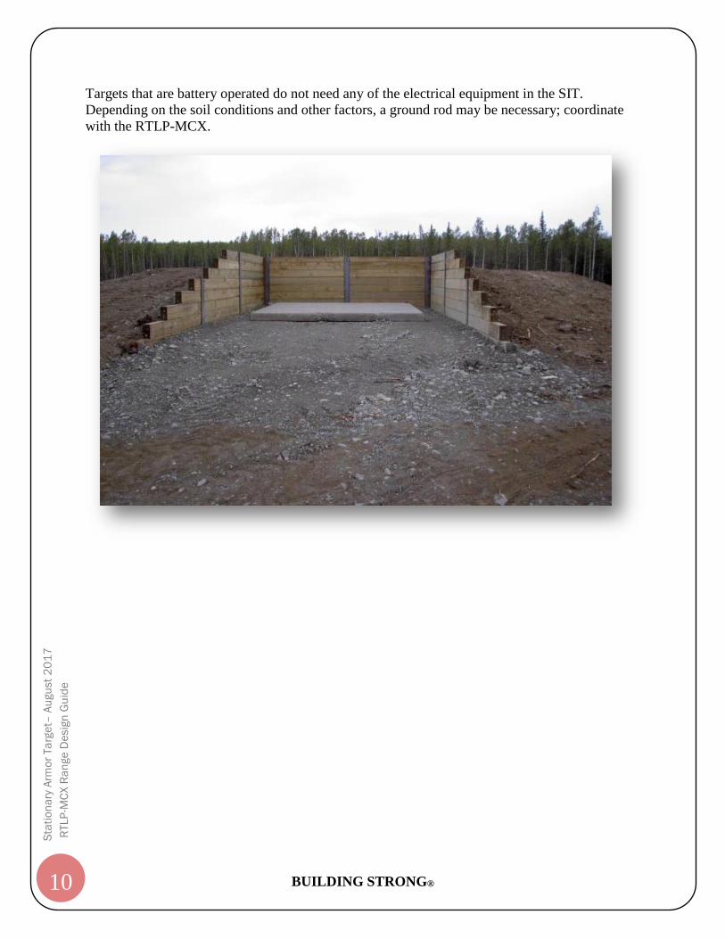
Targets that are battery operated do not need any of the electrical equipment in the SIT.
Depending on the soil conditions and other factors, a ground rod may be necessary; coordinate
with the RTLP-MCX.
%PRODUCTION DATA 1%
SHEET ID
®of Engineers
US Army Corps
SO
LICIT
ATIO
N N
O.:
DE
SIG
NE
D B
Y:
DE
SC
RIP
TIO
N
1
A
MA
RK
SIZ
E:
SU
BMIT
TE
D B
Y:
DA
TE
CO
NT
RA
CT N
O.:
CH
EC
KE
D B
Y:
DR
AW
N B
Y:
ISS
UE D
AT
E:
B
C
D
E
F
G
2 3 4 5 6 7 8 9 10
PR
OJE
CT N
UM
BE
R:
HU
NTS
VIL
LE,
ALA
BA
MA
EN
GIN
EE
RIN
G
& S
UPP
OR
T C
EN
TE
R
U. S.
AR
MY C
ORPS
OF E
NGIN
EE
RS
AU
GU
ST 2017
RA
NG
E A
ND T
RAININ
G L
AN
D P
RO
GR
AM
ST
AN
DA
RD D
ESIG
N M
AN
UA
L
GRAPHIC SCALES:
02 2 4
20
SCALE: 1" = 2'
10010
SCALE: 1" = 10'
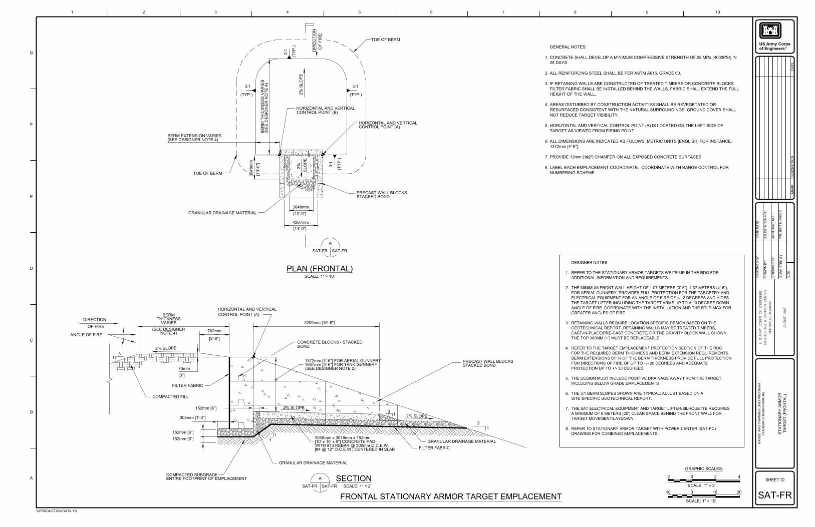
PLAN (FRONTAL)
SECTIONSCALE: 1" = 2'SAT-FRSAT-FR
A
FILTER FABRIC
GRANULAR DRAINAGE MATERIAL
3
1
2% SLOPE
31
[#4 @ 12" O.C.E.W.] CENTERED IN SLABWITH #13 REBAR @ 300mm O.C.E.W.[10' x 10' x 6"] CONCRETE PAD3048mm x 3048mm x 152mm
GRANULAR DRAINAGE MATERIAL
1
1
ENTIRE FOOTPRINT OF EMPLACEMENTCOMPACTED SUBGRADE
152mm [6"]
152mm [6"]
305mm [1'-0"]
152mm [6"] 2% SLOPE
COMPACTED FILL
FILTER FABRIC
[3"]
76mm
CONCRETE BLOCKS - STACKED
BOND
STACKED BONDPRECAST WALL BLOCKS
3200mm [10'-6"]
CONTROL POINT (A)
HORIZONTAL AND VERTICAL
762mm
[2'-6"]
2% SLOPE
NOTE 4)(SEE DESIGNER
VARIESTHICKNESS
BERM
31
ANGLE OF FIRE
OF FIRE
DIRECTION
SCALE: 1" = 10'
SAT-FR SAT-FR
A
[14'-0"]
4267mm
[10'-0"]
3048mm
STACKED BONDPRECAST WALL BLOCKS
GRANULAR DRAINAGE MATERIAL
TOE OF BERM
(TY
P.)
3:1
3048
mm
[10'-0"]
SL
OP
E
CONTROL POINT (A)HORIZONTAL AND VERTICAL
3:1
(TYP.)
CONTROL POINT (B)HORIZONTAL AND VERTICAL
2% S
LO
PE
3:1
(TY
P.)
DIR
EC
TIO
N
OF FIR
E
TOE OF BERM
NUMBERING SCHEME.
LABEL EACH EMPLACEMENT COORDINATE. COORDINATE WITH RANGE CONTROL FOR
PROVIDE 13mm [1#2"] CHAMFER ON ALL EXPOSED CONCRETE SURFACES.
1372mm [4'-6"].
ALL DIMENSIONS ARE INDICATED AS FOLOWS: METRIC UNITS [ENGLISH] FOR INSTANCE,
TARGET AS VIEWED FROM FIRING POINT.
HORIZONTAL AND VERTICAL CONTROL POINT (A) IS LOCATED ON THE LEFT SIDE OF
NOT REDUCE TARGET VISIBILITY.
RESURFACED CONSISTENT WITH THE NATURAL SURROUNDINGS. GROUND COVER SHALL
AREAS DISTURBED BY CONSTRUCTION ACTIVITIES SHALL BE REVEGETATED OR
HEIGHT OF THE WALL.
FILTER FABRIC SHALL BE INSTALLED BEHIND THE WALLS. FABRIC SHALL EXTEND THE FULL
IF RETAINING WALLS ARE CONSTRUCTED OF TREATED TIMBERS OR CONCRETE BLOCKS
ALL REINFORCING STEEL SHALL BE PER ASTM A615, GRADE 60.
28 DAYS.
CONCRETE SHALL DEVELOP A MINIMUM COMPRESSIVE STRENGTH OF 28 MPa (4000PSI) IN
GENERAL NOTES:
8.
7.
6.
5.
4.
3.
2.
1.
3:1
(TYP.)
(SEE DESIGNER NOTE 4)BERM EXTENSION VARIES
(SE
E D
ESIG
NE
R N
OT
E 4)
BE
RM T
HIC
KN
ES
S V
ARIE
S
ST
ATIO
NA
RY A
RM
OR
SAT-FR
TA
RG
ET (F
RO
NT
AL)
FRONTAL STATIONARY ARMOR TARGET EMPLACEMENT
DRAWING FOR COMBINED EMPLACEMENTS.
REFER TO STATIONARY ARMOR TARGET WITH POWER CENTER (SAT-PC)
TARGET MOVEMENT/LAYDOWN.
A MINIMUM OF 6 METERS (20’) CLEAR SPACE BEHIND THE FRONT WALL FOR
THE SAT ELECTRICAL EQUIPMENT AND TARGET LIFTER/SILHOUETTE REQUIRES
SITE-SPECIFIC GEOTECHNICAL REPORT.
THE 3:1 BERM SLOPES SHOWN ARE TYPICAL; ADJUST BASED ON A
INCLUDING BELOW GRADE EMPLACEMENTS
THE DESIGN MUST INCLUDE POSITIVE DRAINAGE AWAY FROM THE TARGET,
PROTECTION UP TO +/- 30 DEGREES.
FOR DIRECTIONS OF FIRE OF UP TO +/- 20 DEGREES AND ADEQUATE
BERM EXTENSIONS OF ¼ OF THE BERM THICKNESS PROVIDE FULL PROTECTION
FOR THE REQUIRED BERM THICKNESS AND BERM EXTENSION REQUIREMENTS.
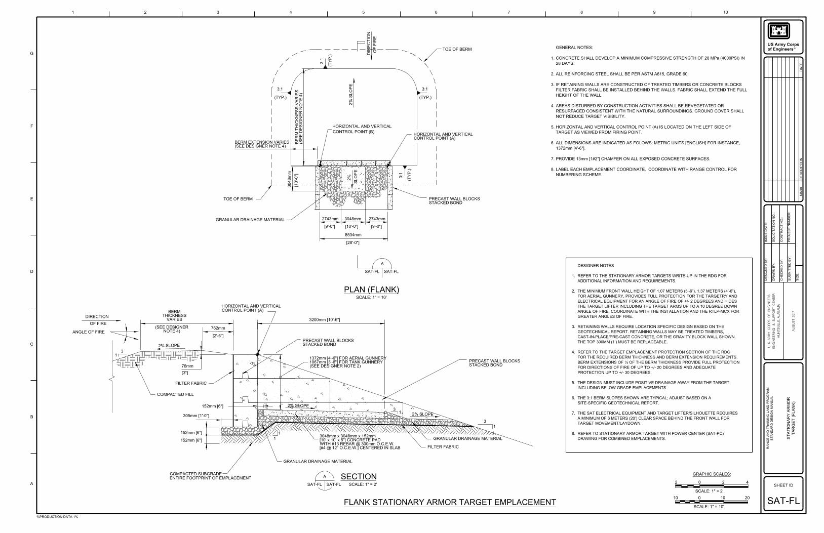
REFER TO THE TARGET EMPLACEMENT PROTECTION SECTION OF THE RDG
THE TOP 300MM (1’) MUST BE REPLACEABLE.
CAST-IN-PLACE/PRE-CAST CONCRETE, OR THE GRAVITY BLOCK WALL SHOWN.
GEOTECHNICAL REPORT. RETAINING WALLS MAY BE TREATED TIMBERS,
RETAINING WALLS REQUIRE LOCATION SPECIFIC DESIGN BASED ON THE
GREATER ANGLES OF FIRE.
ANGLE OF FIRE. COORDINATE WITH THE INSTALLATION AND THE RTLP-MCX FOR
THE TARGET LIFTER INCLUDING THE TARGET ARMS UP TO A 10 DEGREE DOWN
ELECTRICAL EQUIPMENT FOR AN ANGLE OF FIRE OF +/- 2 DEGREES AND HIDES
FOR AERIAL GUNNERY, PROVIDES FULL PROTECTION FOR THE TARGETRY AND
THE MINIMUM FRONT WALL HEIGHT OF 1.07 METERS (3’-6”), 1.37 METERS (4’-6”),
ADDITIONAL INFORMATION AND REQUIREMENTS.
REFER TO THE STATIONARY ARMOR TARGETS WRITE-UP IN THE RDG FOR
DESIGNER NOTES
8.
7.
6.
5.
4.
3.
2.
1.
(SEE DESIGNER NOTE 2)1067mm [3'-6"] FOR TANK GUNNERY1372mm [4'-6"] FOR AERIAL GUNNERY
%PRODUCTION DATA 1%
SHEET ID
®of Engineers
US Army Corps
SO
LICIT
ATIO
N N
O.:
DE
SIG
NE
D B
Y:
DE
SC
RIP
TIO
N
1
A
MA
RK
SIZ
E:
SU
BMIT
TE
D B
Y:
DA
TE
CO
NT
RA
CT N
O.:
CH
EC
KE
D B
Y:
DR
AW
N B
Y:
ISS
UE D
AT
E:
B
C
D
E
F
G
2 3 4 5 6 7 8 9 10
PR
OJE
CT N
UM
BE
R:
HU
NTS
VIL
LE,
ALA
BA
MA
EN
GIN
EE
RIN
G
& S
UPP
OR
T C
EN
TE
R
U. S.
AR
MY C
ORPS
OF E
NGIN
EE
RS
AU
GU
ST 2017
RA
NG
E A
ND T
RAININ
G L
AN
D P
RO
GR
AM
ST
AN
DA
RD D
ESIG
N M
AN
UA
L
GRAPHIC SCALES:
02 2 4
20
SCALE: 1" = 2'
10010
SCALE: 1" = 10'
1
ANGLE OF FIRE
SECTION
PLAN (FLANK)
SCALE: 1" = 2'SAT-FLSAT-FL
A
SAT-FL
A
SAT-FL
SCALE: 1" = 10'
GRANULAR DRAINAGE MATERIAL
ENTIRE FOOTPRINT OF EMPLACEMENTCOMPACTED SUBGRADE
[#4 @ 12" O.C.E.W.] CENTERED IN SLABWITH #13 REBAR @ 300mm O.C.E.W.[10' x 10' x 6"] CONCRETE PAD3048mm x 3048mm x 152mm
FILTER FABRIC
GRANULAR DRAINAGE MATERIAL
STACKED BONDPRECAST WALL BLOCKS
STACKED BONDPRECAST WALL BLOCKS
3200mm [10'-6"]
HORIZONTAL AND VERTICALCONTROL POINT (A)
VARIESTHICKNESS
BERM
NOTE 4)(SEE DESIGNER 762mm
[2'-6"]
2% SLOPE
76mm
[3"]
FILTER FABRIC
COMPACTED FILL
152mm [6"]
305mm [1'-0"]
2% SLOPE
OF FIRE
DIRECTION
31
31
2% SLOPE
3
1
1
1
DIR
EC
TIO
N
OF FIR
E
TOE OF BERM
STACKED BONDPRECAST WALL BLOCKS
CONTROL POINT (A)HORIZONTAL AND VERTICAL
2% S
LO
PE
3:1
(TY
P.)
3048
mm
[10'-0"]
SL
OP
E
2743mm
[9'-0"] [10'-0"] [9'-0"]
2743mm3048mm
8534mm
[28'-0"]
GRANULAR DRAINAGE MATERIAL
TOE OF BERM
(TYP.)
3:1
3:1
(TY
P.)
3:1
(TYP.)
HORIZONTAL AND VERTICAL
CONTROL POINT (B)
(SEE DESIGNER NOTE 4)BERM EXTENSION VARIES
NUMBERING SCHEME.
LABEL EACH EMPLACEMENT COORDINATE. COORDINATE WITH RANGE CONTROL FOR
PROVIDE 13mm [1#2"] CHAMFER ON ALL EXPOSED CONCRETE SURFACES.
1372mm [4'-6"].
ALL DIMENSIONS ARE INDICATED AS FOLOWS: METRIC UNITS [ENGLISH] FOR INSTANCE,
TARGET AS VIEWED FROM FIRING POINT.
HORIZONTAL AND VERTICAL CONTROL POINT (A) IS LOCATED ON THE LEFT SIDE OF
NOT REDUCE TARGET VISIBILITY.
RESURFACED CONSISTENT WITH THE NATURAL SURROUNDINGS. GROUND COVER SHALL
AREAS DISTURBED BY CONSTRUCTION ACTIVITIES SHALL BE REVEGETATED OR
HEIGHT OF THE WALL.
FILTER FABRIC SHALL BE INSTALLED BEHIND THE WALLS. FABRIC SHALL EXTEND THE FULL
IF RETAINING WALLS ARE CONSTRUCTED OF TREATED TIMBERS OR CONCRETE BLOCKS
ALL REINFORCING STEEL SHALL BE PER ASTM A615, GRADE 60.
28 DAYS.
CONCRETE SHALL DEVELOP A MINIMUM COMPRESSIVE STRENGTH OF 28 MPa (4000PSI) IN
GENERAL NOTES:
8.
7.
6.
5.
4.
3.
2.
1.
(SE
E D
ESIG
NE
R N
OT
E 4)
BE
RM T
HIC
KN
ES
S V
ARIE
S
DRAWING FOR COMBINED EMPLACEMENTS.
REFER TO STATIONARY ARMOR TARGET WITH POWER CENTER (SAT-PC)
TARGET MOVEMENT/LAYDOWN.
A MINIMUM OF 6 METERS (20’) CLEAR SPACE BEHIND THE FRONT WALL FOR
THE SAT ELECTRICAL EQUIPMENT AND TARGET LIFTER/SILHOUETTE REQUIRES
SITE-SPECIFIC GEOTECHNICAL REPORT.
THE 3:1 BERM SLOPES SHOWN ARE TYPICAL; ADJUST BASED ON A
INCLUDING BELOW GRADE EMPLACEMENTS
THE DESIGN MUST INCLUDE POSITIVE DRAINAGE AWAY FROM THE TARGET,
PROTECTION UP TO +/- 30 DEGREES.
FOR DIRECTIONS OF FIRE OF UP TO +/- 20 DEGREES AND ADEQUATE
BERM EXTENSIONS OF ¼ OF THE BERM THICKNESS PROVIDE FULL PROTECTION
FOR THE REQUIRED BERM THICKNESS AND BERM EXTENSION REQUIREMENTS.
REFER TO THE TARGET EMPLACEMENT PROTECTION SECTION OF THE RDG
THE TOP 300MM (1’) MUST BE REPLACEABLE.
CAST-IN-PLACE/PRE-CAST CONCRETE, OR THE GRAVITY BLOCK WALL SHOWN.
GEOTECHNICAL REPORT. RETAINING WALLS MAY BE TREATED TIMBERS,
RETAINING WALLS REQUIRE LOCATION SPECIFIC DESIGN BASED ON THE
GREATER ANGLES OF FIRE.
ANGLE OF FIRE. COORDINATE WITH THE INSTALLATION AND THE RTLP-MCX FOR
THE TARGET LIFTER INCLUDING THE TARGET ARMS UP TO A 10 DEGREE DOWN
ELECTRICAL EQUIPMENT FOR AN ANGLE OF FIRE OF +/- 2 DEGREES AND HIDES
FOR AERIAL GUNNERY, PROVIDES FULL PROTECTION FOR THE TARGETRY AND
THE MINIMUM FRONT WALL HEIGHT OF 1.07 METERS (3’-6”), 1.37 METERS (4’-6”),
ADDITIONAL INFORMATION AND REQUIREMENTS.
REFER TO THE STATIONARY ARMOR TARGETS WRITE-UP IN THE RDG FOR
DESIGNER NOTES
8.
7.
6.
5.
4.
3.
2.
1.
(SEE DESIGNER NOTE 2)1067mm [3'-6"] FOR TANK GUNNERY1372mm [4'-6"] FOR AERIAL GUNNERY
ST
ATIO
NA
RY A
RM
OR
SAT-FL
TA
RG
ET (F
LA
NK)
FLANK STATIONARY ARMOR TARGET EMPLACEMENT
152mm [6"]
152mm [6"]