STATE SHEET TOTAL PROJECT OF S.D. Section E: Structure Plans
7
N Section E: Structure Plans PROJECT NO. SHEETS SHEET TOTAL STATE S.D. OF 30 31 7 10 25 26 27 34 35 2 3 13 14 15 P I N E R I DG E 407 R 45 W T 35 N T 36 N 18 18 173 AVE 174 AVE 175 AVE 176 AVE S C H O O L P I N E R I DG E HO L Y R O S A R Y M I SS I ON D S C W h it e C l a y Dam C h e y e nn e R 44 W 11 12 1 36 6 18 INDEX OF SHEETS - Sheet E1 Layout Map and Index Sheet E2 Estimate of Structure Quantities NH 0018(215)101 2 - 10' x 10' Box Culvert Uprgrade (Partial Precast) Sta. 748 + 03.00 Str. No. 57-223-456 2 - 10' x 10' Box Culvert Uprgrade (Partial Precast) Sheet E3 to E7 E1 E7
Transcript of STATE SHEET TOTAL PROJECT OF S.D. Section E: Structure Plans

N
Section E: Structure Plans
PROJECTNO. SHEETS
SHEET TOTALSTATE
S.D.
OF
30
31
710
252627
34 35
23
131415
PINE RIDGE
407
R 45 W
T 35
NT 36
N
18
18
173
AV
E
174
AV
E
175
AV
E
176
AV
E
SCHOOL
PINE RIDGE
HOLY ROSARY
MISSION
D
S
C
White Clay
Dam
Cheyenne
R 44 W
11 12
1
36
6
18
INDEX OF SHEETS -
Sheet E1 Layout Map and Index
Sheet E2 Estimate of Structure Quantities
NH 0018(215)101
2 - 10' x 10' Box Culvert Uprgrade (Partial Precast)
Sta. 748 + 03.00
Str. No. 57-223-456
2 - 10' x 10' Box Culvert Uprgrade (Partial Precast)
Sheet E3 to E7
E1 E7

E2 E7I STATE I PROJECT I SHEET I TOTAL
OF r-~~~~~~~~~~j__~N!QO._ . .J,...£Sil:!H~EE~T:l!S_J
S.D. I NH 0018(215)101 I I I SECTION E- ESTIMATE OF STRUCTURE QUANTITES
Str. Nos. 57-223-456
BID ITEM ITEM
NUMBER QUANTITY UNIT
250E0030 Incidental Work, Structure Lump Sum LS
460E0120 Class A45 Concrete, Box Culvert 12.6 CuYd
460E0380 Install Dowel in Concrete 58 Each
480E0100 Reinforcing Steel 2,100 Lb
560E2124 2-10'x10' Precast Concrete Box Culvert, Furnish 200.0 Ft
560E2125 2-10'x10' Precast Concrete Box Culvert, Install 200.0 Ft
STR. NO. 57-223-456
1 5
HL-93PCN 06JC
S. D. DEPT. OF TRANSPORTATION
OF
FOR
SEC. 36-T36N-R45W
BB TK BT
DESIGNED BY
BRIDGE ENGINEER
DRAFTED BYCK. DES. BY
06JCTA01OGLA06JC
PROJECTNO. SHEETS
SHEET TOTALSTATE
S.D.
OF
ESTIMATED QUANTITIES
ITEM UNIT QUANTITY
Class A45 Concrete, Box Culvert
Lb.Reinforcing Steel
Cu. Yd.
EachInstall Dowel in Concrete 58
12.6
2100
INDEX OF CULVERT SHEETS
Sheet No. 1 - General Drawing and Quantities
-X028-
-X028-
PLANS BY :
OFFICE OF BRIDGE DESIGN, SOUTH DAKOTA DEPARTMENT OF TRANSPORTATION
Incidental Work, Structure L.S.
Ft.
Ft.
200
200
N
GENERAL DRAWING AND QUANTITES
OVER CHEYENNE CREEK
STA. 748 + 03.00
40° LHF SKEW
SEPTEMBER 2017
NH 0018(215)101
NH 0018(215)101
Sheet No. 2 - Notes and Dowel Placement Details
Sheet No. 5 - Details of Standard Plate No's. 460.10 & 560.01
Sheet No. 3 - F10 Barrel End Filler Section Details (5' - 6'') (A)
Sheet No. 4 - F10 Barrel End Filler Section Details (5' - 6'') (B)
Lump Sum
(PARTIAL PRECAST)
2 - 10' X 10' BOX CULVERT UPGRADE
OGLALA LAKOTA COUNTY
precast sections.
Dimension may vary depending on installation of
Based on survey.
Based on 8'' middle wall and 8'' side walls.
2 - 10' X 10' Precast Concrete Box Culvert, Furnish
2 - 10' X 10' Precast Concrete Box Culvert, Install
Existing Box Culvert
Section (Do Not Disturb)
Existing Precast Box Culvert
W.P.
W.P.
2 : 1
Rdw
yLC
Sta. 748 + 17.36
40° LHF
Sta. 748 + 03.00
Sta. 747 + 88.64
22' - 0''
4 : 1 20
' - 0''
Varies
20' - 0''
Varies
22' - 0''
4 : 1
PLAN
8''
10' - 0''
10' - 0''
8''
8''
1
Existing Box Culvert
W.P.
W.P.
FLOW
''87
53' - 9
3 : 1
2 : 1
3 : 1
''85
57' - 0
'' ±16949' - 2
Box C
ulvert
LCF10 = 5' - 6'' (Filler Section) 200' - 0'' Precast Box Culvert 54' - 7'' ±
'' ±169309' - 3
(Typ.)
(Typ.)
Ts
Ts
Tm
W = 1
0' - 0''
LC
Match Existing
Finished ShoulderMatch Existing
Finished ShoulderMatch Existing
Finished
Match Existing Match Existing
H = 1
0' - 0''
Tt
Tb
(Typ.)
at Top of Bottom Slab
Match Existing Flowline Elev.
Section (Do Not Disturb)
Existing Precast Box Culvert Existing Box CulvertExisting Box Culvert
at Top of Bottom Slab
Match Existing Flowline Elev.
10' - 0''
9''
''2
110
1F.L. Grade
Match Existing
W = Width of Opening
H = Height of Opening
Tt = Thickness of Top Slab
Tb = Thickness of Bottom Slab
Ts = Thickness of Side Wall
LEGEND
Tm = Thickness of Middle Wall
ELEVATION
Shoulder
Finished Shoulder
Finished
''16526' - 1 ''16
526' - 1 ''8528' - 8 ''8
528' - 8
Q
dQ
dA
dV
100Q
HYDRAULIC DATA
Vmax
QF
OT
1126 cfs
1126 cfs
2246 cfs
project based on 25 year frequency.
QF = Designated peak discharge for the basin approaching proposed
Q100
= Computed discharge for the basin approaching proposed project
QOT
Qd
= Design discharge for the proposed culvert based on 25 year
frequency. El. 3179.3.
based on 100 year frequency. El. 3183.8.
Vmax
based on 100 year frequency.
>Q100 = Maximum computed outlet velocity for the proposed culvert,
75 sq. ft.
15.0 fps
100Q = Overtopping discharge and frequency > year recurrence
17.9 fps
interval. El. 3205.1 @ Sta. 746 + 00.
Dimension based on original plans, in-place dimension may vary. E3 E7
1. Box culvert and box culvert end section design shall conform to the AASHTO
4. The design of the barrel sections shall be based on a minimum fill height of 2 feet
and include all subsequent fill heights up to and including the maximum fill height
5. Minimum inside corner fillet shall be 6 in.
6. Minimum precast barrel section length shall be 4 ft.
shop plans.
9. Installation of the precast sections shall be in accordance with the final approved
7. Lift holes shall be plugged with an approved nonshrinkable grout.
governed by the Specified Density method.
11. Compaction of earth embankment and box culvert backfill shall be
with the following criteria:
Design shall be in accordance with Section 560 of the South Dakota Specifications
LRFD Bridge Design Specifications, 2014 Edition with 2015 and 2016 interims.
calculations or shop plans, as appropriate.
level. Submit Load Rating calculations with the Design and Check Design
four specialized hauling vehicles shall rate greater than 1.0 at legal load rating
(Inventory Level). The three SD Legal Loads, the notional rating load and the
Bridge Evaluation. All sections of the box culvert shall rate at HL-93 or better
load and four specialized hauling vehicles noted in the AASHTO Manual for
for the three SD legal trucks (Type 3, 3S2 and 3-2) as well as the notional rating
HL-93 truck at both Inventory and Operating levels and at the Legal Load rating
method. The rating shall include evaluation at the Design Load rating for the
Bridge Evaluation, 2011 Edition with latest Interim Revisions using the LRFR
3. The box culvert shall be load rated in accordance with the AASHTO Manual for
through the proper channels, to the Office of Bridge Design for approval.
Contractor shall submit a design analysis for the anticipated construction loading,
construction loads in excess of legal load are anticipated by the Contractor, the
until a minimum of 4 ft. of fill has been placed over the Box Culvert. If
axle with gross weight = 95,850 lbs. The construction load shall not be applied
2. Design Live Load: HL-93 and construction loading consisting of one 7' - 6'' gage
included in the Proposal.
and Required Provisions, Supplemental Specifications and Special Provisions as
Use South Dakota Standard Specifications for Roads and Bridges, 2015 Edition
the lifting holes by approved equipment.
10. Care shall be taken when placing sections. Sections shall be only moved using
Specifications, and Special Provisions as included in the Proposal.
and Bridges, 2015 Edition and required Provisions, Supplemental
2. Construction Specifications: South Dakota Standard Specifications for Roads
Edition with 2008 and 2009 interims.
1. Design Specifications: AASHTO LRFD Bridge Design Specifications, 2007
GENERAL NOTES CAST-IN-PLACE PORTION
SPECIFICATIONS PRECAST PORTIONS
GENERAL NOTES PRECAST PORTIONS
STR. NO. 57-223-456
2 5
HL-93
S. D. DEPT. OF TRANSPORTATION
OF
FOR
SEC. 36-T36N-R45W
BB TK BT
DESIGNED BY
BRIDGE ENGINEER
DRAFTED BYCK. DES. BY
06JCTA01OGLA06JC
PROJECTNO. SHEETS
SHEET TOTALSTATE
S.D.
OF
OVER CHEYENNE CREEK
STA. 748 + 03.00
40° LHF SKEW
SEPTEMBER 2017
NH 0018(215)101
NH 0018(215)101
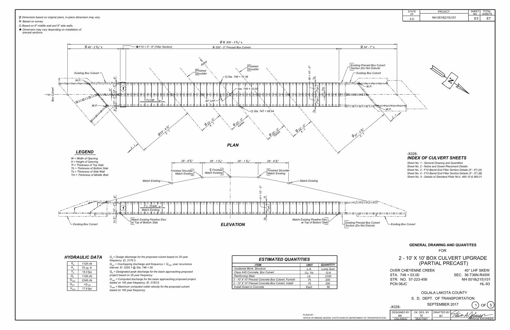
NOTES AND DOWEL PLACEMENT DETAILS
INSTALLING DOWELS IN CONCRETE
1. The epoxy resin mixture shall be of a type for bonding steel to hardened concrete and
2. The diameter of the drilled holes shall not be less than 1/8 inch greater, nor more
than 3/8 inch greater than the diameter of the dowels or as per the Manufacturer’s recommendations. Holes shall not be drilled using core bits. The drilled holes shall be
blown out with compressed air using a device that will reach the back of the hole to
ensure that all debris or loose material has been removed prior to epoxy injection.
to 1/2 full of epoxy, or as recommended by the Manufacturer, prior to insertion of the
steel bar. Care shall be taken to prevent epoxy from running out of the horizontal holes
prior to steel bar insertion. Rotate the steel bar during installation to eliminate voids
and ensure complete bonding of the bar. Insertion of the bars by the dipping or painting
4. No loads shall be applied to the epoxy grouted dowel bars until the epoxy resin has had
sufficient time to cure as specified by the epoxy resin manufacturer.
6. z2 dowel bars shall be #6 deformed bars conforming to ASTM A615 Grade 60.
7. The cost of drilling holes, epoxy resin, dowels, installation and other incidental
items shall be included in the contract unit price per each for Install Dowel in Concrete.
methods will not be allowed.
Each
ESTIMATED QUANTITIES
ITEM UNIT QUANTITY
Install Dowel in Concrete 58
(Inlet end only)
Grade 3).
shall conform to AASHTO M235 Type IV, Grade 3 (Equivalent to ASTM C881, Type IV,
3. Mix epoxy resin as recommended by the Manufacturer and apply by an injection method
as approved by the Engineer. Beginning at the back of the drilled holes, fill the holes 1/3
z2 bars to be drilled in and
Existing Box Culvert
8''
DETAIL ''X''
grouted with Epoxy. (Typ.)
Box C
ulvert
LC
See DETAIL ''X''
Existing Box Culvert
PLAN - DOWEL DETAILS
(Inlet end only)
z2 bars to be drilled in and
grouted with Epoxy (Typ.)
22' - 0''
Box Culvert
LC
19 Spaces @ 12'' = 19' - 0'' (Typ.)1' - 6''
''2
14
''4
15
1' - 6''
1' - 3''
1' - 3''
5 S
paces @ 1
8''
= 7' - 6''
(Typ.)4'' (Typ.)
19 Spaces @ 12'' = 19' - 0'' (Typ.)2' - 0''
23' - 0''
VIEW A - A(Dowel Locations)
2' - 0''
A
A
Saw Cut Line
Saw Cut Line
ELEVATION - SAW CUT DETAILS
PLAN - SAW CUT DETAILS
Existing Box Culvert
Existing Box Culvert be removed)
Culvert Sections (To
Existing Precast Box
be removed)
Culvert Sections (To
Existing Precast Box
DESIGN MIX OF CONCRETE PRECAST PORTIONS
section, shall incorporate tie reinforcing steel and a 2'' x 3'' (nominal) keyway as follows:
The end of the precast section, at the construction joint between precast and C. I. P.
cast-in-place section members.
the full length of the slabs and walls, and positioned to be centered in the adjoining
2. The keyway shall be fabricated into the end of the precast section, continuous for
TIE QUANITITES" shall be fabricated into the end of the precast section.
Transportation STANDARD PLATE NO. 460.10 titled "BOX CULVERT BARREL
1. Tie reinforcement matching the size length, and spacing shown of the S. D. Dept. of
CONSTRUCTION JOINT
not be less than 4500 p.s.i. at 28 days.
1. Mix shall be as per fabricator's design, however minimum compressive strength shall
2. Type II cement is required.
INCIDENTAL WORK, STRUCTURE
interference with existing bars.
5. Embed z2 dowels 8” into existing concrete, dowels may be shifted 2'' maximum to avoid
of 25 ft. over the box culvert.
by more than 2 inches from that of the plan shown barrel section.
8. The interior wall thickness of the precast concrete section must not differ
(PARTIAL PRECAST)
2 - 10' X 10' BOX CULVERT UPGRADE
OGLALA LAKOTA COUNTY
SHOP PLANS
design and check design, if applicable, with initial submittal.
The fabricator shall submit shop plans in accordance with the specifications. Include
FOUNDATION PREPARATION
new RCBC.
be wetted then proof rolled to ensure adequate density prior to placement of the
be replaced and compacted according to Section 421. At a minimum, the area shall
underlying material. Any material disturbed from removal of the existing RCBC shall
The contractor shall remove the existing RCBC with minimal disturbance to the
SPECIFICATIONS CAST-IN-PLACE PORTION
governed by the Specified Density method.
8. Compaction of earth embankment and box culvert backfill material shall be
section I.D. Numbers (see SDDOT Materials Manual).
7. Circled numbers in PLAN and ELEVATION views on the General Drawing are
6. Use 1 inch clear cover on all reinforcing steel EXCEPT as shown.
inch.435. All exposed edges shall be chamfered
4. All reinforcing steel shall conform to ASTM A615 Grade 60.
3. All concrete shall be Class A45 conforming to Section 460.
Reinforcing Steel fy = 60000 p.s.i.
2. Design Material Strengths: Concrete f'c = 4500 p.s.i.
of 10 ft. (F10).
includes all subsequent fill heights up to and including the maximum fill height
1. The design of the barrel section is based on a minimum fill height of 2 feet and
DIMENSIONS OF EXISTING BOX CULVERT
. obtained from the Office of Bridge Design
Original construction plans can becompletion of the work required for this project.
actual field conditions and any necessary dimensions affecting the satisfactory
provided as information only. It is the Contractor's responsibility to inspect and verify
All details and dimensions of the Existing Box Culvert, contained in these plans, are
to the unit price per foot for 2 - 10' x 10' Precast Concrete Box Culvert, Furnish.
3. All costs associated with furnishing the tie reinforcing and keyway shall be incidental
original construction plans may be obtained through the Office of Bridge Design.
extent of the work and materials involved. If desired by the Contractor, a copy of the
responsibility of the Contractor to make a visual inspection of the structure to verify the
construed to be complete in all details. Before preparing the bid it shall be the
3. The foregoing is a general description of the in-place structure and should not be
Contractor will be required to load the salvaged section.
Contact Forterra, Inc. at (605)737-5208 to arrange pickup of the salvaged section. The
Contractor in accordance with ENVIRONMENTAL COMMITMENTS in SECTION A.
2. All portions of the existing not salvaged shall be removed and disposed of by the
site for pickup by Forterra, Inc.
place. One 6' section of the precast box culvert removed shall be salvaged and stored on
existing 2 - 10' x 10' precast box culvert, leaving the last section next to the outlet end in
1. Incidental work, Structure shall consist of the removal and disposal of 205.5' of the
E4 E7
STR. NO. 57-223-456
3 5
HL-93
S. D. DEPT. OF TRANSPORTATION
OF
FOR
SEC. 36-T36N-R45W
TK BT
DESIGNED BY
BRIDGE ENGINEER
DRAFTED BYCK. DES. BY
06JCTA03OGLA06JC
PROJECTNO. SHEETS
SHEET TOTALSTATE
S.D.
OF
OVER CHEYENNE CREEK
STA. 748 + 03.00
40° LHF SKEW
SEPTEMBER 2017
NH 0018(215)101
NH 0018(215)101
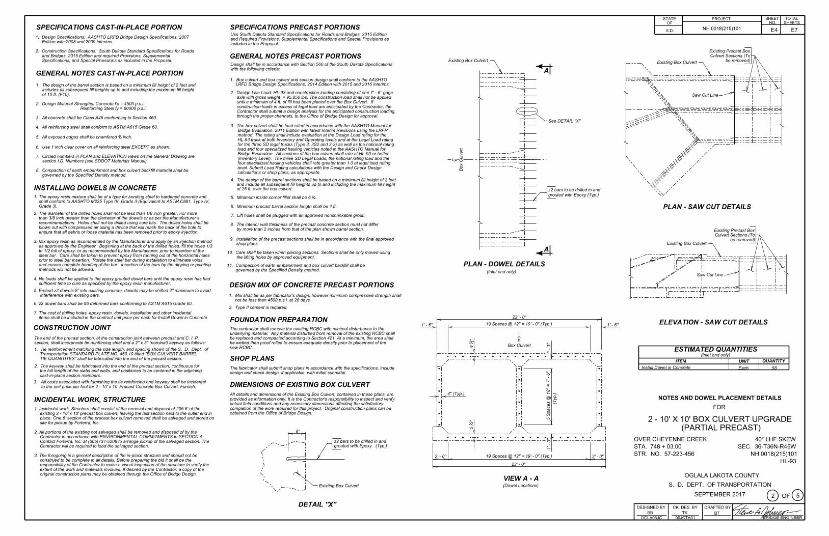
LEGEND FOR PLACING RE-STEEL
T.T.S. - Top of Top Slab
B.T.S. - Bottom of Top Slab
T.B.S. - Top of Bottom Slab
B.B.S. - Bottom of Bottom Slab
F10 BARREL END FILLER SECTION DETAILS (5' - 6'') (A)
(PARTIAL PRECAST)
2 - 10' X 10' BOX CULVERT UPGRADE
OGLALA LAKOTA COUNTY
3''3''
3''3''
8''8''
F10 = 5' - 6''
3'' 3''
p2
Keyway (Typ.)
2'' X 3''
k2
T.T.S.
j2
p2 @ 12''
s2
p2
Box C
ulvert
LC
Sy
m.
Abt.
PLAN(Top Slab)
p2
n2
p2 @ 12''
B.T.S.
3''3''
3''3''
8''8''
F10 = 5' - 6''
3'' 3''
''413 ''4
13
3'' 3''w2 ~ 5 Spaces @ 12'' = 5' - 0''
s2 ~ 5 Spaces @ 10'' = 4' - 2''
m2 ~ 12 Spaces @ 5'' = 5' - 0''
j2 ~ 6 Spaces @ 10'' = 5' - 0''
k2 ~ 10 Spaces @ 6'' = 5' - 0''
''21'' = 4' - 11 2
1h2 ~ 7 Spaces @ 8
s2 ~ 5 Spaces @ 10'' = 4' - 2''
n2 ~ 10 Spaces @ 6'' = 5' - 0''
j2 ~ 6 Spaces @ 10'' = 5' - 0''
k2 ~ 10 Spaces @ 6'' = 5' - 0''
k2
k2
p2
p2
h2
h2
k2
s2
j2
p2 @ 12''
w2 p2
m2
p2 @ 12''
T.B.S.
B.B.S.
PLAN(Bottom Slab)
precast sections.
Dimension may vary depending on installation of
NOTE:
BB
E5 E7

STR. NO. 57-223-456
4 5
HL-93
S. D. DEPT. OF TRANSPORTATION
OF
FOR
SEC. 36-T36N-R45W
BB TK BT
DESIGNED BY
BRIDGE ENGINEER
DRAFTED BYCK. DES. BY
06JCTA04OGLA06JC
PROJECTNO. SHEETS
SHEET TOTALSTATE
S.D.
OF
OVER CHEYENNE CREEK
STA. 748 + 03.00
40° LHF SKEW
SEPTEMBER 2017
NH 0018(215)101
NH 0018(215)101
M. W. - Middle Wall
I.F.O.W . - Inside Face of Outside Wall
O.F.O.W. - Outside Face of Outside Wall
LEGEND FOR PLACING RE-STEEL
F10 BARREL END FILLER SECTION DETAILS (5' - 6'') (B)
Mk. No. Size Length Type Bending Details
Str.
All dimensions are out to out of bars.
the Contractor.
Box CulvertITEM
UNIT Lb.
Class A45 Reinforcing
Steel
Str.h2
(Exact)
Type 17
k2
OPTIONAL k2 SPLICE DETAIL
j2
k2
m2
n2
z2
14
13
11
6
5
4
5
4
6
20' - 9''
22' - 9''
Str.
Str.
Str.
2' - 3''
Cu.Yd.
Concrete,
ESTIMATED QUANTITIES
REINFORCING SCHEDULE
Type 17A
58
22 17
min. la
p
NOTES:
p2
h2 4 17A16
5' - 3''
1' - 9''
12.6 2100
Quantity of z2 bars is not included in reinforcing steel.
than those shown, must be submitted to the Engineer for prior
approval. If additional splices are approved, no payment will be
allowed for the added quantity of reinforcing steel.
''214' - 8
''214' - 8
Contractor may use optional reinforcing steel splice, as shown.
The cost of the additional reinforcing steel shall be borne by
Request for additional reinforcing steel splices at points other
12' - 0''
21' - 9''
11''
(Typ.)
See NOTES AND DOWEL PLACEMENT DETAILS Sheet.
123
20' - 9''
4w2
6 Str.s2 4' - 6''12
6 25' - 0''
''2
111' - 4
''4
36' - 6
12'' w2
(Exact)
(Exact)
Type S11A
6''
S11A
11' - 4''
8''
p2 s2
(10' - 0'' Maximum Fill)
1' - 4''1' - 4''
8'' 8''10' - 0''10' - 0''
1' - 8'' 1' - 8''
11' - 0'' 11' - 0''
22' - 0''
8 Spaces @ 12'' = 8' - 0'' 8 Spaces @ 12'' = 8' - 0''
1' - 4'' 1' - 4''2' - 2'' 8 Spaces @ 12'' = 8' - 0'' 2' - 2''8 Spaces @ 12'' = 8' - 0''
p2 p2
12''
(Typ.)
(Typ.)
12''6''6'' 6''9 Spaces @ 12'' = 9' - 0'' (Typ.)
'' Cl.
21
1
2''
Cl.
j2
m2p2
Constr. Jt. (Typ.)
''2
11' - 10
''2
12' - 1
5 S
paces @ 1
8''
= 7' - 6''
''2
111' - 7
2' - 0''
p2
p2
p2
k2
h2
Opt. Const. Jt. (Typ.)
n2
j2 p2 s2
p2
p2
p2
k2
h2
p2
p2
w2
23' - 0''
10' - 0''
9''
''2
110
(For One F10 Barrel End FIller Section)
F10 BARREL HALF SECTION
(PARTIAL PRECAST)
2 - 10' X 10' BOX CULVERT UPGRADE
OGLALA LAKOTA COUNTY
Keyway (Typ.)
2'' X 3''
Keyway (Typ.)
2'' X 3''
Keyway (Typ.)
2'' X 3''
p2
p2
k2
p2 @ 18''O.
F.O.
W.
s2
j2p2
n2
p2 @ 18''
w2
M.W.
m2
s2
j2p2
ELEVATION
k2p2
m2
p2 @ 18''
h2
I.F.O.W.
k2p2
n2
1 - F10 Barrel End Filler Section @ 5' - 6''
E6 E7

E7 E7
t= s: z1 bars spaced@ 12" 6' u.: ~
(Typ.) ....;
"' "" lJJ ~~ ~ 't) ~
a,~ (.)::, <llO
"',;_ ~~ i~
6" z1 bars spaced@ 12" 6" -.... (Typ.)
~F
TYPICAL SINGLE BARREL VIEW A - A
LEGEND FOR PLACING RE-STEEL I. F. W. - Inside Face Wall
t= s: 6' z1 bars spaced @ 12" 6' u.: (Typ.) ....;~
2o ~ lJJ -~ ~ Q)
't) ~ Q) ~ (.) ::, "'O "',;_ ~~
z1 bars spaced @ 12" -0 ~ 6" N (Typ.)
~F TYPICAL MULTIPLE BARREL VIEW A - A
p
p bars@ 18"
F "". ,. .
1'- 9" 1'- 9"
z1
z1@ 18" ( I. F. W. )
2" x 3" Keyway (Typ.)
z1
ELEVATION
a, (.)
.I!! ... a,
~ ~ a, ~ ~ ~ @) .g 't) .'!l a, .!:: (.)
[ ~ "'I'-~ "' -0
RISE "X" 3'-0" 3"
4'-0" 9"
5'-0" 6"
6'-0" 3"
7'-0" 9"
8'-0" 6"
9'-0" 3" 10'-0" 9" 11'- O" 6" 12'- O" 3"
GENERAL NOTES: 1. z1 bars shall be placed in the
middle of the 2" X 3" keyway in the top and bottom slabs. z1 bars shall be lapped with the longitudinal p bars in the inside face of the wall for outside walls and in either face for interior walls. z1 bars are listed and included elsewhere in plans.
2. Drainage Fabric Protection shall be placed in accordance with Section 422, or Section 560, whichever is applicable.
June 26. 2012
s 0 0 0 T
BOX CULVERT BARREL TIE REINFORCEMENT PLATE NUMBER
460.10
Published Date: 3rd Otr. 2019 Sheet I of I
ct Hole
I 16" 16"
·p..JJJom< 2" long 1 ~" ¢ (nominal pipe size) double extra strong pipe sleeve or approved equal. (Typ.)
32" (Adj. ± 1 W Min.)
TIE BOLT ASSEMBLY
GENERAL NOTES: 1. All holes for tie bolts shall be cast-in-place, 16 inches from
outside edge of joint. Cast in inserts or sleeves, if used, shall be made of a corrosion resistant material.
STATE OF
S.D.
2. Ties shall be 1 inch a! and conform to the requirements of ASTM A36, ASTM A307, or ASfM F1554, Gr. 36. Nuts shall be heavy hex in conformance with ASTM A563. Washers shall conform to ASTM F436, Type 1. The welded pipe sleeve shall conform to ASTM A53, Grade B.
3. Welding and weld inspection shall be in conformance with AWS/ANSI 01.1 - (Current Year) Structural Welding Code - Steel.
4. Tie Bolt Assembly shall be galvanized in accordance with ASTM A 153 or ASTM F2329 as applicable.
5. Tie Bolt Assembly details may vary from that shown, but alternate tie bolt assemblies are subject to testing to demonstrate equal strength. Submit details, through proper channels, to the Office of Bridge Design for approval.
6. All costs for furnishing and installing the precast box culvert tie bolt assembly shall be incidental to the contract unit price per Foot for "Precast Concrete Box Culvert, Furnish".
. I
PROJECT
NH 0018(215)101
March 21, 2016
PLATE NUMBER
560.01
SHEET TOTAL NO. SHEETS
Published Date: 3rd Otr. 2019
s 0 0 0 T
PRECAST BOX CULVERT TIE BOLT ASSEMBLY DETAILS
Sheet I of I
2 - 1 O' X 1 O' BOX CULVERT UPGRADE (PARTIAL PRECAST)
STR. NO. 57-223-456 SEPTEMBER 2017 G)oFG)