STATE OF SOUTH DAKOTA Revised 2-9-18 MP ... -...
26
C L AY U N I O N B ON HO MME YANK T ON CHARLES MI X HU T C H I N S ON T U R N E R L I N C O L N MI NN E HAHA Mc C O OK HAN S O N DAV I S ON JERAULD S AN B O R N MINER L AK E MO O D Y BR OOK I N G S K I NG S B U R Y SPINK C OD I N G T ON HA ML I N D E U L EDMUNDS CAMPBELL McPHERSON MA R S HA LL R O B E R T S HA R D I NG CORSON ZIEBACH DEWEY ME AD E B U TTE C U S TE R F A LL R I V E R P E R K I N S L A WR E N C E P E NN I NG T ON WALWORTH AU R O R A DOUGLAS BEADLE CLARK G R AN T DAY BROWN DEPARTMENT OF TRANSPORTATION ASPHALT SURFACE TREATMENT STORM WATER PERMIT NO PERMIT REQUIRED OG L A L A - L AK O T A PCN 05L4 SD HIGHWAY 34 - MRM 245.00+0.498 TO MRM 257.06+0.000 INDEX OF SHEETS Project Layout Maps Title Sheet Estimate of Quantities Plan Notes Permanent Pavement Markings Standard Plates Fixed Location Sign Layout Typical Sections N E W S Sheet No. 1 Sheet Nos. 2-6 Sheet No. 18 Sheet No. 19 Sheet Nos. 20-24 Sheet Nos. 25-26 PROJECT LOCATIONS Environmental Commitments STATE OF SOUTH DAKOTA PLANS FOR PROPOSED SD 73 SD 1806 SD 34 US HIGHWAY 212 - MRM 235.00+0.816 TO MRM 245.00+0.034 SD HIGHWAY 47 - MRM 189.91+0.000 TO MRM 199.94+0.000 PROJECT NH-P 0031(34) SD HIGHWAY 73 - MRM 78.26+0.080 TO MRM 92.93+0.000 SD HIGHWAY 1806 - MRM 164.43+0.000 TO MRM 180.05+0.000 BUFFALO HYDE HAND HUGHES POTTER FAULK HAAKON JACKSON LYMAN TRIPP B E N N ET T JONES STANLEY SULLY TODD MELLETTE GREGORY BRULE SD 47 Sheet No. 9 Sheet Nos. 7-8 Sheet Nos. 10-13 Sheet Nos. 15-17 Sign Tabulation PROJECT NO. SHEETS SHEET TOTAL STATE S.D. OF Sheet No. 14 Table of Additional Quantities Rates of Materials and JACKSON, POTTER & STANLEY COUNTIES FAULK, HAAKON, HUGHES, HYDE, SD HIGHWAYS 34, 47, 73 & 1806 US HIGHWAY 212, PROJECT NH-P 0031(34) US 212 F A U L K 45 47 20 20 1 2 2 H ov e n S e n ec a F AU L K T ON T o l s t oy Onaka W ec o t a G ETT Y S B U R G 34 47 34 26 47 47 45 45 273 Blunt Harrold Holabird HIGHMORE MILLER Mac’s Corner Thompson Fort Lee’s Corner Polo VALLEY GANN Brule Lower H Y D E B U F F A L O Orient 249 1 806 1 4 1 2 2 Big Bend Dam MI SSOURI R I V E R 47 L Y M A N Reliance KENNEBEC Shelby P OTTE R 1 2 83 2 804 1 MI SSOURI RI VER H A A KON S TA N L E Y H U GH E S J ON E S 1 4 1 4 1 4 1 4 83 83 83 34 34 63 73 1 1 1 806 804 804 O t t u m w a PHILIP M i d l a nd H a y e s Ridge M i ss i on Agar ONIDA F O R T P I E RR E L a k e O a h e B a d R i v e r 90 90 63 KADOKA M U R DO B e l v i d e r e D r a p e r V i v i a n Presho Dam Oahe O k a t on R ee H e i gh t s L e b a non 204 73 90 S U L L Y PIERRE J A CKS ON NH-P 0031(34) 1 26 Revised 2-9-18 MP 7
Transcript of STATE OF SOUTH DAKOTA Revised 2-9-18 MP ... -...

CLAY UNIONBON HOMMEYANKTON
CHARLES
MIX
HUTCHINSON TURNERLINCOLN
MINNEHAHAMcCOOKHANSONDAVISON
JERAULD SANBORN MINER LAKE MOODY
BROOKINGSKINGSBURY
SPINK
CODINGTON
HAMLIN
DEUL
EDMUNDS
CAMPBELL McPHERSON MARSHALL ROBERTSHARDING
CORSON
ZIEBACH DEWEY
MEADE
BUTTE
CUSTER
FALL RIVER
PERKINS
LAWRENCE
PENNINGTON
WALWORTH
AURORA
DOUGLAS
BEADLE
CLARK
GRANT
DAY
BROWN
DEPARTMENT OF TRANSPORTATION
ASPHALT SURFACE TREATMENT
STORM WATER PERMIT
NO PERMIT REQUIRED
OGLALA-LAKOTA
PCN 05L4
SD HIGHWAY 34 - MRM 245.00+0.498 TO MRM 257.06+0.000
INDEX OF SHEETS
Project Layout Maps
Title Sheet
Estimate of Quantities
Plan Notes
Permanent Pavement Markings
Standard Plates
Fixed Location Sign Layout
Typical Sections
N
EW
S
Sheet No. 1
Sheet Nos. 2-6
Sheet No. 18
Sheet No. 19
Sheet Nos. 20-24
Sheet Nos. 25-26
PROJECT LOCATIONS
Environmental Commitments
STATE OF SOUTH DAKOTA
PLANS FOR PROPOSED
SD 73
SD 1806
SD 34
US HIGHWAY 212 - MRM 235.00+0.816 TO MRM 245.00+0.034
SD HIGHWAY 47 - MRM 189.91+0.000 TO MRM 199.94+0.000
PROJECT NH-P 0031(34)
SD HIGHWAY 73 - MRM 78.26+0.080 TO MRM 92.93+0.000
SD HIGHWAY 1806 - MRM 164.43+0.000 TO MRM 180.05+0.000
BUFFALO
HYDE HAND
HUGHES
POTTER
FAULK
HAAKON
JACKSON
LYMAN
TRIPP
BENNETT
JONES
STANLEY
SULLY
TODD
MELLETTE
GREGORY
BRULE
SD 47
Sheet No. 9
Sheet Nos. 7-8
Sheet Nos. 10-13
Sheet Nos. 15-17
Sign Tabulation
PROJECTNO. SHEETS
SHEET TOTALSTATE
S.D.
OF
Sheet No. 14
Table of Additional Quantities
Rates of Materials and
JACKSON, POTTER & STANLEY COUNTIESFAULK, HAAKON, HUGHES, HYDE, SD HIGHWAYS 34, 47, 73 & 1806
US HIGHWAY 212, PROJECT NH-P 0031(34)
US 212
F A U L K45
47
20
20
1 22
Hoven
Seneca
FAULKTON
Tolstoy
Onaka
Wecota
GETTYSBURG
34
47
34
26
47
47
45
45
273
BluntHarrold
Holabird
HIGHMORE
MILLER
Mac’s Corner
Thompson
Fort
Lee’s Corner
Polo
VALLEY
GANNBrule
Lower
H Y D E
B U F F A L O
Orient
249
1 806
1 4
1 22
Big
Bend
Dam
MIS
SO
URI
RIVER
47
L Y M A N
Reliance
KENNEBEC
Shelby
P O T T E R 1 2
83
2
8041
MIS
SO
URI
RIV
ER
H A A K O N
S T A N L E Y
H U G H E S
J O N E S
1 4
1 4
1 4
1 4
83
83
83
3434
63
73
1
1
1806
804
804
Ottumwa
PHILIP
Midland
Hayes
Ridge
Mission
Agar
ONIDA
FORT PIERRE
Lake
Oahe
Bad
River
90
90
63
KADOKA
MURDO
Belvidere
Draper Vivian
Presho
Dam
Oahe
Okaton
Ree Heights
Lebanon
204
73
90
S U L L Y
PIERRE
J A C K S O N
NH-P 0031(34) 1 26Revised 2-9-18 MP
7
11 12
2
3635
26 25
2423
216 ST
215 ST
212 ST
211 ST
H
Y
D
E
C
O
U
N
T
Y
19 20 21 22 23 24
2526282930
33 3435 36
4 3
78 9 10
12
18 17 16 14 13
19 20 21 22 24
26 2930
19 20
30 29 28
333231
22 23 24
27 26 25
34 35 36
19 20 21
30 29 28
31 32 33
6 5 4
8
18 17 16
19 20 21
33
28
3231
3
10 12
15 13
2324
27 25
34 35 36
2 1 6 5 4
31 33
29 28
1920 21
17 16
8 97
47
34
34
47
34
4.1
56
C R O W
C R E E K
I N D I A N
R E S E R V A T I O N
B U F F A L O C O U N T Y
R 71 WR 72 W
H
U
G
H
E S
C
O
U
N
T
Y
T 109
N
T 110
NT 109
N
212 ST
213 ST
214 ST
215 ST
216 ST
217 ST
218 ST
219 ST
220 ST
326
AV
E
327
AV
E
329
AV
E
330
AV
E
331
AV
E
333
AV
E
334
AV
E
335
AV
E
338
AV
E
339
AV
E
340
AV
E
341
AV
E
336
AV
E
CROW CREEK
TRIBAL SCHOOL
STEPHAN
R 73 W
R 73 W TO
HIG
HM
OR
ET
O
FO
RT
TH
OM
PS
ON
TO PIERREMILEAGE = 207.029
MRM 257.06 + 0.000
STA. 609+94.56
END SD 34
MILEAGE = 195.477
MRM 245.00 + 0.498
STA. 0+00
BEGIN SD 34
DESIGN DESIGNATION
NET LENGTH:
LENGTH OF EXCEPTIONS:
GROSS LENGTH:
SD HIGHWAY 34
SD HIGHWAY 34
V 65 MPH
T ADT 12.8%
T DHV 5.8%
D 50%
DHV 98
ADT (2036) 778
ADT (2016) 595
PROJECTNO. SHEETS
SHEET TOTALSTATE
S.D.
OF
60994.56 FEET = 11.552 MILES
0.00 FEET = 0.000 MILES
60994.56 FEET = 11.552 MILES
HUGHES & HYDE COUNTIESSD HIGHWAY 34
ASPHALT SURFACE TREATMENTPROJECT LAYOUT
NH-P 0031(34) 2 26Revised 2-9-18 MP
DESIGN DESIGNATION
NET LENGTH:
LENGTH OF EXCEPTIONS:
GROSS LENGTH:
52,858.08 FEET = 10.011 MILES
SD HIGHWAY 47
SD HIGHWAY 47
POTTER COUNTYSD HIGHWAY 47
ASPHALT SURFACE TREATMENTPROJECT LAYOUT
0.00 FEET = 0.000 MILES
52,858.08 FEET = 10.011 MILES
V 65 MPH
T ADT 29.5%
T DHV 13.4%
D 51%
DHV 50
ADT (2036) 459
ADT (2016) 450
LE
BA
NO
N
HO
VE
N
20
47
20
20
47
47
R 75
WR 74
WW
A
L
W
O
R
T
H
C
O
U
N
T
Y
TO J
CT.
SD 45
T 120 NT 119 N
212
314 AVE
315 AVE
316 AVE
317 AVE
318 AVE
320 AVE
321 AVE
322 AVE
PO
P. 4
06
PO
P. 4
7
TO JCT. US 12
R 74
W
TO J
CT.
SD 45
TO
GE
TT
YS
BU
RG
TO J
CT.
US 83
MILEAGE = 137.987
MRM 189.91+0.000
STA. 0+00
BEGIN SD 47
MILEAGE 147.998
MRM 199.94+0.000
STA. 528+58.08
END SD 47
13
14
15
12
11
103
21
36
35
3427
26
2524
23
2215
14
13
12
11
103
2136
35
34
27
26
2524
23
22
15
14
13
12
11
103
21
23
6 78
910
11
14
15
16
17
18
19
20
21
22
23
26
27
28
29
30
31
33
34
35
34
56 7
89
10
11
14
15
17
18
23
21
20
19
26
27
28
29
30
31
32
33
35
23
56 7
89
10
11
14
15
16
17
18
0.7
9.0
PROJECTNO. SHEETS
SHEET TOTALSTATE
S.D.
OF
NH-P 0031(34) 263
DESIGN DESIGNATION
NET LENGTH:
LENGTH OF EXCEPTIONS:
GROSS LENGTH:
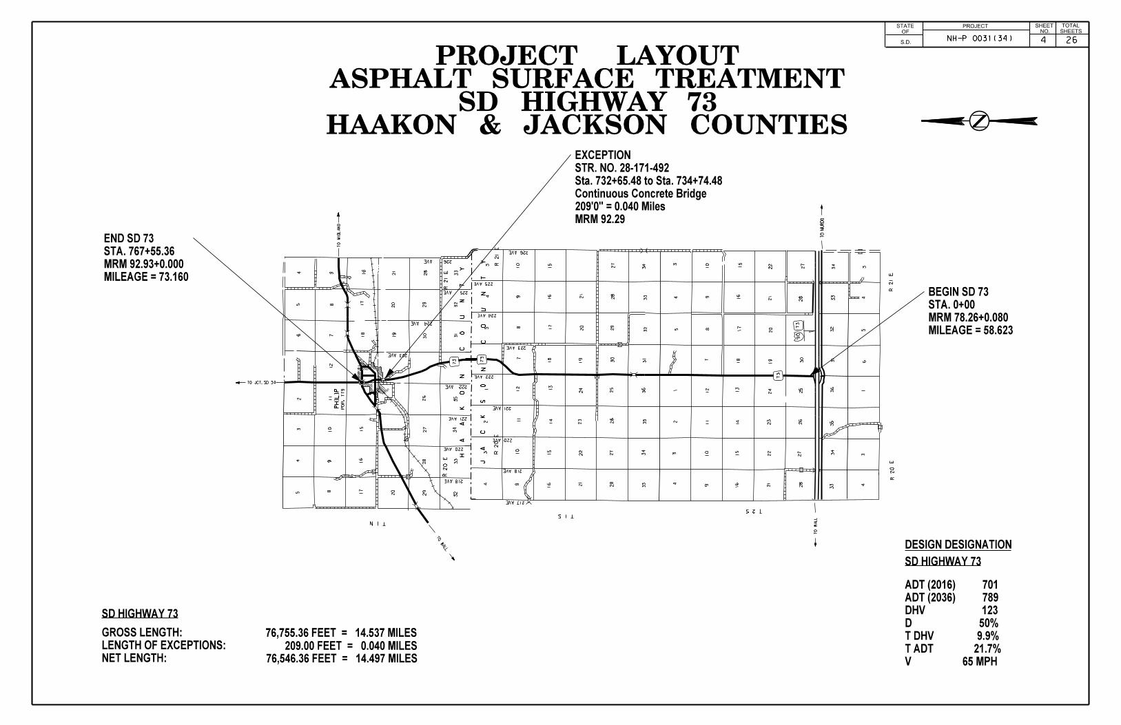
SD HIGHWAY 73
SD HIGHWAY 73
V 65 MPH
T ADT 21.7%
T DHV 9.9%
D 50%
DHV 123
ADT (2036) 789
ADT (2016) 701
HAAKON & JACKSON COUNTIESSD HIGHWAY 73
ASPHALT SURFACE TREATMENTPROJECT LAYOUT
76,755.36 FEET = 14.537 MILES
PHILIP
73
J
A
C
K S
O
N
C
O
U
N
T
Y
R 20
ER 21 E
T 1 N
218 AVE
220 AVE
221 AVE
222 AVE
223 AVE
224 AVE
225 AVE
226 AVE
PO
P. 7
79
73
73
H
A
A
K
O
N
C
O
U
N
T
Y
R 20
ER 21 E
T 1 S
R 21 E
R 20
E
217 AVE
218 AVE
220 AVE
221 AVE
222 AVE
223 AVE
224 AVE
225 AVE
226 AVE
T 2 S
TO
MID
LA
ND
TO JCT. SD 34
TO
MU
RD
O
TO
WA
LL
90
73
TO
WALL
MILEAGE = 58.623
MRM 78.26+0.080
STA. 0+00
BEGIN SD 735
43
2
89
10
11
12
15
16
17
20
26
27
28
29
32
33
34
35
65
4
78
9 16
17
18
19
20
21
28
29
30 31
32
33
10
103
45
78
9
15
16
17
18
19
20
21
27
28
29
30
31
32
33
34 3
45
78
9
15
16
17
18
19
20
21
22
27
28
30
31
32
33
34
34
56
1 1 1
10
10
23
4 911
12 13
14
15
16 21
22
23
24
25
26
27
28
33
34
35
36
23
4 911
12 13
14
15
16 21
22
23
24
25
26
27
28
33
34
35
36
34
MRM 92.29
209’0" = 0.040 Miles
Continuous Concrete Bridge
Sta. 732+65.48 to Sta. 734+74.48
STR. NO. 28-171-492
EXCEPTION
209.00 FEET = 0.040 MILES
76,546.36 FEET = 14.497 MILES
MILEAGE = 73.160
MRM 92.93+0.000
STA. 767+55.36
END SD 73
PROJECTNO. SHEETS
SHEET TOTALSTATE
S.D.
OF
NH-P 0031(34) 4 26
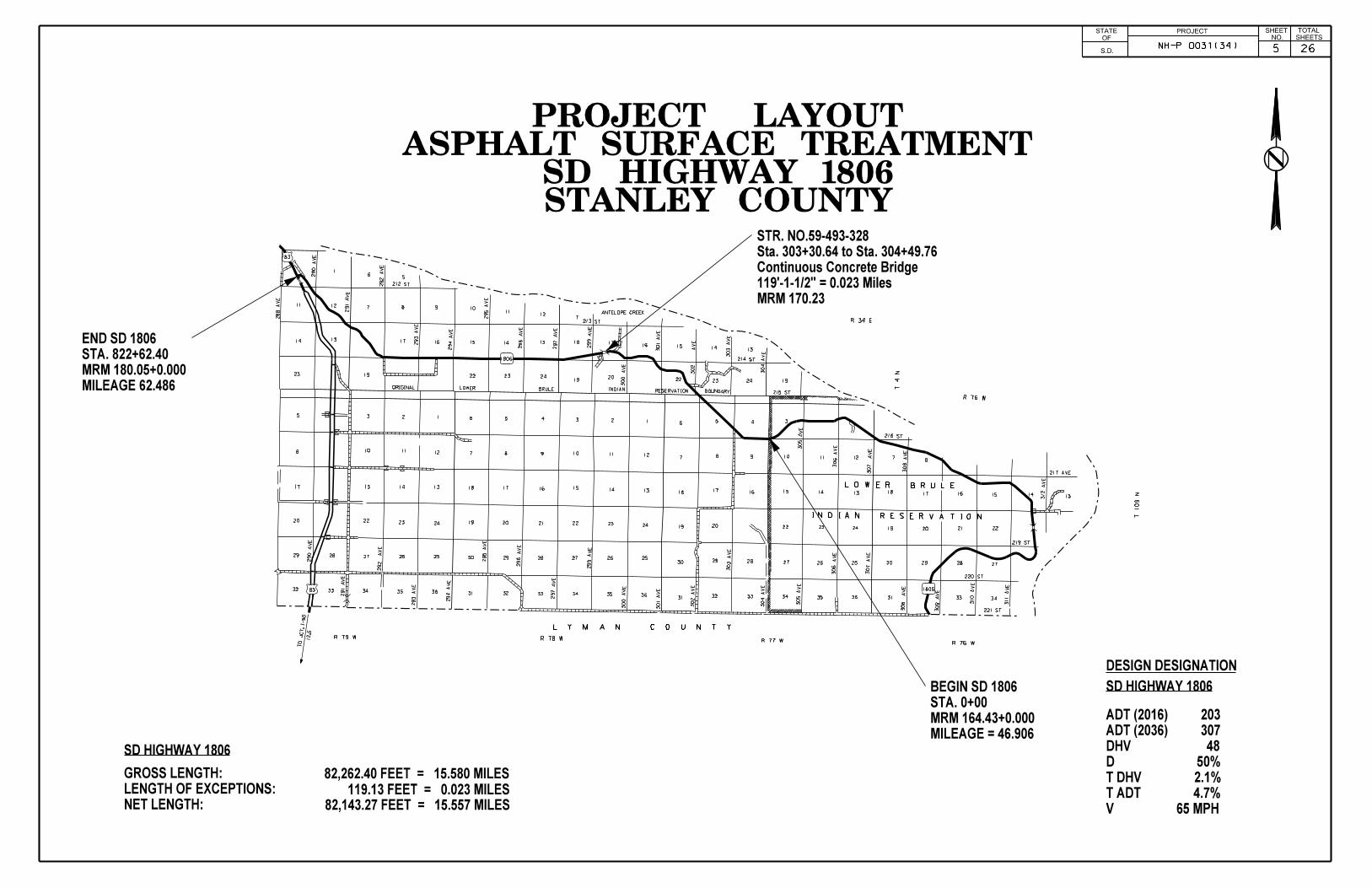
DESIGN DESIGNATION
NET LENGTH:
LENGTH OF EXCEPTIONS:
GROSS LENGTH:
V 65 MPH
T ADT 4.7%
T DHV 2.1%
D 50%
DHV 48
ADT (2036) 307
ADT (2016) 203
STANLEY COUNTYSD HIGHWAY 1806
ASPHALT SURFACE TREATMENTPROJECT LAYOUT
SD HIGHWAY 1806
SD HIGHWAY 1806
82,262.40 FEET = 15.580 MILES
82,143.27 FEET = 15.557 MILES
MRM 170.23
119’-1-1/2" = 0.023 Miles
Continuous Concrete Bridge
Sta. 303+30.64 to Sta. 304+49.76
STR. NO.59-493-328
3456
7 8 9 10 11 12
131415161718
19 20 22 23 24
252627282930
31 32 33 34 35 36
123456
7 8 9 10 11 12
131415161718
19 20 21 22 23 24
252627282930
31 32 33 34 35 36
78
131415161718
19
20 21 22
27282930
31 33 34
1235
8 10 11 12
13141517
20 22 23 24
2526272829
32 33 34 35 36
19
242322
15 14 13
2019
18 1716
242322
15 14 13
1211
10
7
987
65
19
17 1613
12
14
11
23
1
83
83
1806
ORIGINAL LOWER BRULE INDIAN RESERVATION BOUNDARY
L O W E R B R U L E
I N D I A N R E S E R V A T I O N
290
AV
E
291
AV
E
292
AV
E
293
AV
E
294
AV
E
295
AV
E
296
AV
E
297
AV
E
299
AV
E
300
AV
E
301
AV
E
302
AV
E
303
AV
E
304
AV
E
305
AV
E
306
AV
E
307
AV
E
308
AV
E
309
AV
E
310
AV
E
311
AV
E
312
AV
E
293
AV
E
292
AV
E
291
AV
E
290
AV
E
288
AV
E
294
AV
E
295
AV
E
296
AV
E
297
AV
E
299
AV
E
300
AV
E
301
AV
E
302
AV
E
303
AV
E
304
AV
E
305
AV
E
306
AV
E
307
AV
E
308
AV
E
212 ST
213 ST
214 ST
215 ST
216 ST
217 AVE
219 ST
220 ST
221 ST
R 34 E
T 4
N
R 76 W
T 109
N
1806
ANTELOPE CREEK
R 76 WR 77 WR 78 WR 79 W
L Y M A N C O U N T Y
TO J
CT. I-90
12.5
MILEAGE = 46.906
MRM 164.43+0.000
STA. 0+00
BEGIN SD 1806
119.13 FEET = 0.023 MILES
MILEAGE 62.486
MRM 180.05+0.000
STA. 822+62.40
END SD 1806
PROJECTNO. SHEETS
SHEET TOTALSTATE
S.D.
OF
NH-P 0031(34) 265
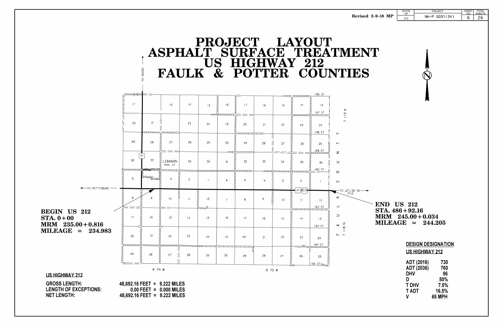
DESIGN DESIGNATION
NET LENGTH:
LENGTH OF EXCEPTIONS:
GROSS LENGTH:
48,692.16 FEET = 9.222 MILES
US HIGHWAY 212
US HIGHWAY 212
0.00 FEET = 0.000 MILES
48,692.16 FEET = 9.222 MILES
V 65 MPH
T ADT 16.5%
T DHV 7.5%
D 50%
DHV 96
ADT (2036) 760
ADT (2016) 730
TO
HO
VE
N
TO GETTYSBURG
LEBANON
13141517
24232120
2526272829
32 3335 36
1235
8 9 10 11 12
1314151617
20 21 22 23 24
252627282930 29 28 27 26 25
19 20 21 22 23 24
18 17 16 15 14 13
121110987
6 5 4 3 2 1
363534333231
30 29 28 27 26 25
242322212019
18 17 16 15 14 13
47 212
47
TO JCT. SD 45
27.5
T 119
NT 118
N
F
A
U
L
K
C
O
U
N
T
Y
R 73 W
156 ST
157 ST
158 ST
159 ST
160 ST
162 ST
163 ST
164 ST
165 ST
POP. 47
R 74 W
PROJECTNO. SHEETS
SHEET TOTALSTATE
S.D.
OF
FAULK & POTTER COUNTIESUS HIGHWAY 212
ASPHALT SURFACE TREATMENTPROJECT LAYOUT
MILEAGE = 234.983
MRM 235.00+0.816
STA. 0+00
BEGIN US 212
NH-P 0031(34)
MILEAGE = 244.205MRM 245.00+0.034STA. 486+92.16END US 212
6 26Revised 2-9-18 MP

ESTIMATE OF QUANTITIES PROJECT STATE OF
SOUTH DAKOTA
NH-P 0031(34)
SHEET
7 26
TOTAL SHEETS
ESTIMATE OF QUANTITIES
The quantities of asphalt for surface treatment and cover aggregate are based on the rates shown in the Rates of Materials. This is only an estimate. The actual application rates of materials will be determined by mix design as stated in these plans. The mix design rates may vary from the estimated rates stated in the Rates of Materials depending on the aggregate source and the variation in gradation and flakiness index. The application rates may also be adjusted in the field due to results of gradations, flakiness index, and differing surface conditions. Pay quantities will be those actually used even though they may vary significantly from plans estimates.
BID ITEM NUMBER ITEM QUANTITY UNIT
009E0010 Mobilization LUMP SUM LS
330E0300 SS-1h or CSS-1h Asphalt for Fog Seal 259.5 Ton
330E3000 Sand for Fog Seal 90.0 Ton
360E0020 AE150S Asphalt for Surface Treatment 1,253.3 Ton
360E1020 Type 1B Cover Aggregate 2,688.8 Ton
360E1020 Type 1B Cover Aggregate 1,445.1 Ton
360E1020 Type 1B Cover Aggregate 3,256.5 Ton
360E1020 Type 1B Cover Aggregate 2,204.1 Ton
360E1020 Type 1B Cover Aggregate 1,368.5 Ton
633E1200 Waterborne Pavement Marking Paint with High Grade Polymer, White 2,942 Gal
633E1205 Waterborne Pavement Marking Paint with High Grade Polymer,Yellow 832 Gal
633E6005 Pavement Marking Masking, 5" 12,666 Ft
633E6010 Pavement Marking Masking, 9" 806 Ft
633E6015 Pavement Marking Masking, 13" 384 Ft
633E6020 Pavement Marking Masking, 25" 352 Ft
633E6025 Pavement Marking Masking, Area 400 SqFt
633E6030 Pavement Marking Masking, Arrow 4 Each
633E6045 Pavement Marking Masking, Railroad Crossing 4 Each
634E0010 Flagging 780.0 Hour
634E0020 Pilot Car 200.0 Hour
634E0110 Traffic Control Signs 2,324.6 SqFt
634E0120 Traffic Control, Miscellaneous LUMP SUM LS
634E0630 Temporary Pavement Marking 121.7 Mile
998E0100 Railroad Protective Insurance LUMP SUM LS
SPECIFICATIONS Standard Specifications for Roads and Bridges, 2015 Edition and Required Provisions, Supplemental Specifications, and Special Provisions as included in the Proposal.
Revised 2-9-18 MP

ESTIMATE OF QUANTITIES (FOR INFORMATION ONLY) PROJECT STATE OF
SOUTH DAKOTA
NH-P0031(34)
SHEET
8 26
TOTAL SHEETS
BID ITEM NUMBER ITEM SD34 SD47 SD73 SD1806 US212 QUANTITY UNIT
009E0010 Mobilization Lump Sum Lump Sum Lump Sum Lump Sum Lump Sum LUMP SUM LS
330E0300 SS-1h or CSS-1h Asphalt for Fog Seal 54.4 41.8 68.8 62.2 32.3 259.5 Ton
330E3000 Sand for Fog Seal 10.0 10.0 50.0 10.0 10.0 90.0 Ton
360E0020 AE150S Asphalt for Surface Treatment 311.3 164.3 368.6 250.5 158.6 1,253.3 Ton
360E1020 Type 1B Cover Aggregate 2688.8 - - - - 2,688.8 Ton
360E1020 Type 1B Cover Aggregate - 1445.1 - - - 1,445.1 Ton
360E1020 Type 1B Cover Aggregate - - 3256.5 - - 3,256.5 Ton
360E1020 Type 1B Cover Aggregate - - - 2204.1 - 2,204.1 Ton
360E1020 Type 1B Cover Aggregate - - - - 1368.5 1,368.5 Ton
633E1200 Waterborne Pavement Marking Paint with High Grade Polymer, White 571 480 665 770 456 2,942.0 Gal
633E1205 Waterborne Pavement Marking Paint with High Grade Polymer,Yellow 119 112 316 213 72 832.0 Gal
633E6005 Pavement Marking Masking, 5" - 12346 320 - - 12,666.0 Ft
633E6010 Pavement Marking Masking, 9" - 806 - - - 806.0 Ft
633E6015 Pavement Marking Masking, 13" - - 384 - - 384.0 Ft
633E6020 Pavement Marking Masking, 25" - - 352 - - 352.0 Ft
633E6025 Pavement Marking Masking, Area - - 400 - - 400.0 SqFt
633E6030 Pavement Marking Masking, Arrow - - 4 - - 4.0 Each
633E6045 Pavement Marking Masking, Railroad Crossing - - 4 - - 4.0 Each
634E0010 Flagging 150.0 130.0 180.0 200.0 120.0 780.0 Hour
634E0020 Pilot Car 40.0 35.0 45.0 50.0 30.0 200.0 Hour
634E0110 Traffic Control Signs 456.9 479.2 483.7 452.4 452.4 2,324.6 SqFt
634E0120 Traffic Control, Miscellaneous Lump Sum Lump Sum Lump Sum Lump Sum Lump Sum LUMP SUM LS
634E0630 Temporary Pavement Marking 23.104 20.022 28.994 31.114 18.444 121.7 Mile
998E0100 Railroad Protective Insurance - - - LUMP SUM LS
Revised 2-9-18 MP
Lump Sum -
Revised 2-12-18 SL

ENVIRONMENTAL COMMITMENTS PROJECT STATE OF
SOUTH DAKOTA
NH-P 0031(34)
SHEET
9 26
TOTAL SHEETS
ENVIRONMENTAL COMMITMENTS An Environmental Commitment is a measure that SDDOT commits to implement in order to avoid, minimize, and/or mitigate a real or potential environmental impact. Environmental commitments to various agencies and the public have been made to secure approval of this project. An agency mentioned below with permitting authority can influence a project if perceived environmental impacts have not been adequately addressed. Unless otherwise designated, the Contractor’s primary contact regarding matters associated with these commitments will be the Project Engineer. These environmental commitments are not subject to change without prior written approval from the SDDOT Environmental Office. The environmental commitments associated with this project are as follows: COMMITMENT B: FEDERALLY THREATENED, ENDANGERED, AND PROTECTED SPECIES COMMITMENT B2: WHOOPING CRANE The Whooping Crane is a spring and fall migratory bird in South Dakota that is about 5 feet tall and typically stops on wetlands, rivers, and agricultural lands along their migration route. An adult Whooping Crane is white with a red crown and a long, dark, pointed bill. Immature Whooping Cranes are cinnamon brown. While in flight, their long necks are kept straight and their long dark legs trail behind. Adult Whooping Cranes' black wing tips are visible during flight. Action Taken/Required: Harassment or other measures to cause the Whooping Crane to leave the site is a violation of the Endangered Species Act. If a Whooping Crane is sighted roosting in the vicinity of the project, borrow pit, or staging site associated with the project, cease construction activities in the affected area until the Whooping Crane departs and contact the Project Engineer. The Project Engineer will contact the Environmental Office so that the sighting can be reported to USFWS. COMMITMENT E: STORM WATER Construction activities constitute less than 1 acre of disturbance. Action Taken/Required: At a minimum and regardless of project size, appropriate erosion and sediment control measures must be installed to control the discharge of pollutants from the construction site.
COMMITMENT H: WASTE DISPOSAL SITE The Contractor shall furnish a site(s) for the disposal of construction and/or demolition debris generated by this project. Action Taken/Required: Construction and/or demolition debris may not be disposed of within the Public ROW. The waste disposal site(s) shall be managed and reclaimed in accordance with the following from the General Permit for Construction/Demolition Debris Disposal Under the South Dakota Waste Management Program issued by the Department of Environment and Natural Resources. The waste disposal site(s) shall not be located in a wetland, within 200 feet of surface water, or in an area that adversely affects wildlife, recreation, aesthetic value of an area, or any threatened or endangered species, as approved by the Project Engineer. If the waste disposal site(s) is located such that it is within view of any ROW, the following additional requirements shall apply: 1. Construction and/or demolition debris consisting of concrete, asphalt concrete, or other similar materials shall be buried in a trench completely separate from wood debris. The final cover over the construction and/or demolition debris shall consist of a minimum of 1 foot of soil capable of supporting vegetation. Waste disposal sites provided outside of the Public ROW shall be seeded in accordance with Natural Resources Conservation Service recommendations. The seeding recommendations may be obtained through the appropriate County NRCS Office. The Contractor shall control the access to waste disposal sites not within the Public ROW through the use of fences, gates, and placement of a sign or signs at the entrance to the site stating “No Dumping Allowed”. 2. Concrete and asphalt concrete debris may be stockpiled within view of the ROW for a period of time not to exceed the duration of the project. Prior to project completion, the waste shall be removed from view of the ROW or buried and the waste disposal site reclaimed as noted above. The above requirements will not apply to waste disposal sites that are covered by an individual solid waste permit as specified in SDCL 34A-6-58, SDCL 34A-6-1.13, and ARSD 74:27:10:06. Failure to comply with the requirements stated above may result in civil penalties in accordance with South Dakota Solid Waste Law, SDCL 34A-6-1.31. All costs associated with furnishing waste disposal site(s), disposing of waste, maintaining control of access (fence, gates, and signs), and reclamation of the waste disposal site(s) shall be incidental to the various contract items.
COMMITMENT I: HISTORICAL PRESERVATION OFFICE CLEARANCES The SDDOT has obtained concurrence with the State Historical Preservation Office (SHPO or THPO) for all work included within the project limits and all department designated sources and designated option material sources, stockpile sites, storage areas, and waste sites provided within the plans. Action Taken/Required: All earth disturbing activities not designated within the plans require review of cultural resources impacts. This work includes, but is not limited to: Contractor furnished material sources, material processing sites, stockpile sites, storage areas, plant sites, and waste areas. The Contractor shall arrange and pay for a cultural resource survey and/or records search. The Contractor has the option to contact the state Archaeological Research Center (ARC) at 605-394-1936 or another qualified archaeologist, to obtain either a records search or a cultural resources survey. A record search might be sufficient for review; however, a cultural resources survey may need to be conducted by a qualified archaeologist. The Contractor shall provide ARC with the following: a topographical map or aerial view on which the site is clearly outlined, site dimensions, project number, and PCN. If applicable, provide evidence that the site has been previously disturbed by farming, mining, or construction activities with a landowner statement that artifacts have not been found on the site. The Contractor shall submit the records search or cultural resources survey report and if the location of the site is within the current geographical or historic boundaries of any South Dakota reservation to SDDOT Environmental Engineer, 700 East Broadway Avenue, Pierre, SD 57501-2586 (605-773-3180). SDDOT will submit the information to the appropriate SHPO/THPO. Allow 30 Days from the date this information is submitted to the Environmental Engineer for SHPO/THPO review. If evidence for cultural resources is uncovered during project construction activities, then such activities shall cease and the Project Engineer shall be immediately notified. The Project Engineer will contact the SDDOT Environmental Engineer in order to determine an appropriate course of action. SHPO/THPO review does not relieve the Contractor of the responsibility for obtaining any additional permits and clearances for Contractor furnished material sources, material processing sites, stockpile sites, storage areas, plant sites, and waste areas that affect wetlands, threatened and endangered species, or waterways. The Contractor shall provide the required permits and clearances to the Project Engineer at the preconstruction meeting.
PLAN NOTES PROJECT STATE OF
SOUTH DAKOTA
NH-P0031(34)
SHEET NO.
26
TOTAL SHEETS
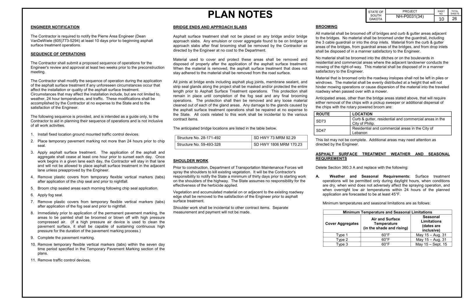
ENGINEER NOTIFICATION
The Contractor is required to notify the Pierre Area Engineer (Dean VanDeWiele (605)773-5294) at least 10 days prior to beginning asphalt surface treatment operations. SEQUENCE OF OPERATIONS The Contractor shall submit a proposed sequence of operations for the Engineer's review and approval at least two weeks prior to the preconstruction meeting. The Contractor shall modify the sequence of operation during the application of the asphalt surface treatment if any unforeseen circumstances occur that affect the installation or quality of the asphalt surface treatment. Circumstances that may affect the installation include, but are not limited to, weather, 24 hour temperatures, and traffic. These modifications shall be accomplished by the Contractor at no expense to the State and to the satisfaction of the Engineer. The following sequence is provided, and is intended as a guide only, to the Contractor to aid in planning their sequence of operations and is not inclusive of all work activities. 1. Install fixed location ground mounted traffic control devices.
2. Place temporary pavement marking not more than 24 hours prior to chip seal.
3. Apply asphalt surface treatment. The application of the asphalt and aggregate shall cease at least one hour prior to sunset each day. Once work begins in a given lane each day, the Contractor will stay in that lane and will not be allowed to place asphalt surface treatment in the adjacent lane unless preapproved by the Engineer.
4. Remove plastic covers from temporary flexible vertical markers (tabs) after application of the chip seal and prior to nightfall.
5. Broom chip sealed areas each morning following chip seal application.
6. Apply fog seal.
7. Remove plastic covers from temporary flexible vertical markers (tabs) after application of the fog seal and prior to nightfall.
8. Immediately prior to application of the permanent pavement marking, the areas to be painted shall be broomed or blown off with high pressure compressed air. (If a high pressure air device is used to clean the pavement surface, it shall be capable of sustaining continuous high pressure for the duration of the pavement marking process.)
9. Complete the pavement marking.
10. Remove temporary flexible vertical markers (tabs) within the seven day time period specified in the Temporary Pavement Marking section of the plans.
11. Remove traffic control devices.
BRIDGE ENDS AND APPROACH SLABS
Asphalt surface treatment shall not be placed on any bridge and/or bridge approach slabs. Any emulsion or cover aggregate found to be on bridges or approach slabs after final brooming shall be removed by the Contractor as directed by the Engineer at no cost to the Department. Material used to cover and protect these areas shall be removed and disposed of properly after the application of the asphalt surface treatment. When the material is removed, the asphalt surface treatment that does not stay adhered to the material shall be removed from the road surface.
All joints at bridge ends including asphalt plug joints, membrane sealant, and strip seal glands along the project shall be masked and/or protected the entire length prior to Asphalt Surface Treatment operations. This protection shall remain in place until completion of the fog seal and any final brooming operations. The protection shall then be removed and any loose material cleaned out of each of the gland areas. Any damage to the glands caused by the asphalt surface treatment operations shall be repaired at no expense to the State. All costs related to this work shall be incidental to the various contract items.
The anticipated bridge locations are listed in the table below.
Structure No. 28-171-492 SD HWY 73 MRM 92.29
Structure No. 59-493-328 SD HWY 1806 MRM 170.23
SHOULDER WORK Prior to construction, Department of Transportation Maintenance Forces will spray the shoulders to kill existing vegetation. It will be the Contractor's responsibility to notify the State a minimum of thirty days prior to starting work on the shoulders of the highway. The State assumes no responsibility for the effectiveness of the herbicide applied. Vegetation and accumulated material on or adjacent to the existing roadway edge shall be removed to the satisfaction of the Engineer prior to asphalt surface treatment. Shoulder work shall be incidental to other contract items. Separate measurement and payment will not be made.
BROOMING All material shall be broomed off of bridges and curb & gutter areas adjacent to the bridges. No material shall be broomed under the guardrail, including the 3 cable guardrail or into the drop inlets. Material from the curb & gutter areas of the bridges, from guardrail areas of the bridges, and from drop inlets shall be disposed of in a manner satisfactory to the Engineer. No material shall be broomed into the ditches or on the boulevards in residential and commercial areas where the adjacent landowner conducts the mowing of the right-of-way. This material shall be disposed of in a manner satisfactory to the Engineer. Material that is broomed onto the roadway inslopes shall not be left in piles or windrows. The material shall be evenly distributed at a height that will not hinder mowing operations or cause dispersion of the material into the traveled roadway when passed over with a mower. Anticipated areas, other than the bridge areas stated above, that will require either removal of the chips with a pickup sweeper or additional dispersal of the chips with the rotary powered broom are: ROUTE LOCATION
SD73 Curb & gutter, residential and commercial areas in the City of Philip.
SD47 Residential and commercial areas in the City of Lebanon
This list may not be complete. Additional areas may need attention as directed by the Engineer.
ASPHALT SURFACE TREATMENT WEATHER AND SEASONAL REQUIREMENTS Delete Section 360.3 A and replace with the following:
A. Weather and Seasonal Requirements: Surface treatment
operations will be permitted only during daylight hours, when conditions are dry, when wind does not adversely affect the spraying operation, and when overnight low air temperatures within 24 hours of the planned application are forecasted to be at least 45°F.
Minimum temperatures and seasonal limitations are as follows:
Minimum Temperature and Seasonal Limitations
Cover Aggregates Air and Surface
Temperature (in the shade and rising)
Seasonal Limitations (dates are inclusive)
Type 1 60°F May 15 – Aug. 31 Type 2 60°F May 15 – Aug. 31 Type 3 60°F May 15 – Sept. 15
10
PLAN NOTES PROJECT STATE OF
SOUTH DAKOTA
NH-P0031(34)
SHEET NO.
26
TOTAL SHEETS
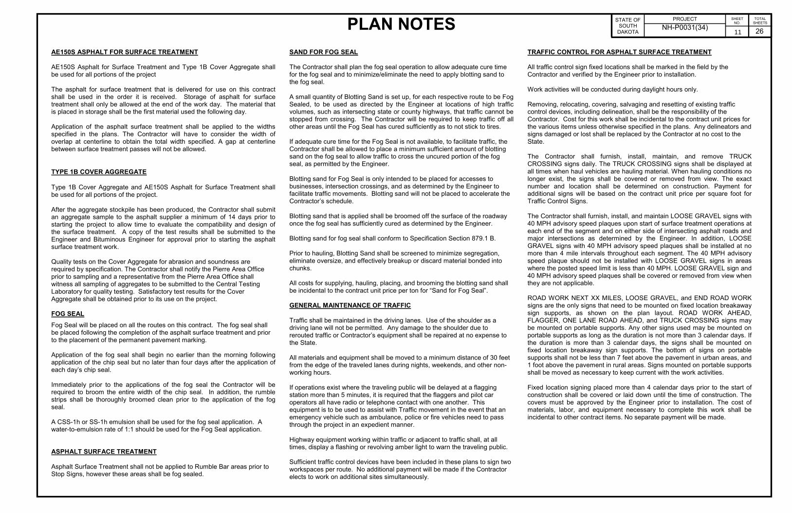
AE150S ASPHALT FOR SURFACE TREATMENT AE150S Asphalt for Surface Treatment and Type 1B Cover Aggregate shall be used for all portions of the project The asphalt for surface treatment that is delivered for use on this contract shall be used in the order it is received. Storage of asphalt for surface treatment shall only be allowed at the end of the work day. The material that is placed in storage shall be the first material used the following day. Application of the asphalt surface treatment shall be applied to the widths specified in the plans. The Contractor will have to consider the width of overlap at centerline to obtain the total width specified. A gap at centerline between surface treatment passes will not be allowed.
TYPE 1B COVER AGGREGATE
Type 1B Cover Aggregate and AE150S Asphalt for Surface Treatment shall be used for all portions of the project. After the aggregate stockpile has been produced, the Contractor shall submit an aggregate sample to the asphalt supplier a minimum of 14 days prior to starting the project to allow time to evaluate the compatibility and design of the surface treatment. A copy of the test results shall be submitted to the Engineer and Bituminous Engineer for approval prior to starting the asphalt surface treatment work. Quality tests on the Cover Aggregate for abrasion and soundness are required by specification. The Contractor shall notify the Pierre Area Office prior to sampling and a representative from the Pierre Area Office shall witness all sampling of aggregates to be submitted to the Central Testing Laboratory for quality testing. Satisfactory test results for the Cover Aggregate shall be obtained prior to its use on the project. FOG SEAL Fog Seal will be placed on all the routes on this contract. The fog seal shall be placed following the completion of the asphalt surface treatment and prior to the placement of the permanent pavement marking. Application of the fog seal shall begin no earlier than the morning following application of the chip seal but no later than four days after the application of each day’s chip seal. Immediately prior to the applications of the fog seal the Contractor will be required to broom the entire width of the chip seal. In addition, the rumble strips shall be thoroughly broomed clean prior to the application of the fog seal. A CSS-1h or SS-1h emulsion shall be used for the fog seal application. A water-to-emulsion rate of 1:1 should be used for the Fog Seal application. ASPHALT SURFACE TREATMENT Asphalt Surface Treatment shall not be applied to Rumble Bar areas prior to Stop Signs, however these areas shall be fog sealed.
SAND FOR FOG SEAL The Contractor shall plan the fog seal operation to allow adequate cure time for the fog seal and to minimize/eliminate the need to apply blotting sand to the fog seal. A small quantity of Blotting Sand is set up, for each respective route to be Fog Sealed, to be used as directed by the Engineer at locations of high traffic volumes, such as intersecting state or county highways, that traffic cannot be stopped from crossing. The Contractor will be required to keep traffic off all other areas until the Fog Seal has cured sufficiently as to not stick to tires. If adequate cure time for the Fog Seal is not available, to facilitate traffic, the Contractor shall be allowed to place a minimum sufficient amount of blotting sand on the fog seal to allow traffic to cross the uncured portion of the fog seal, as permitted by the Engineer. Blotting sand for Fog Seal is only intended to be placed for accesses to businesses, intersection crossings, and as determined by the Engineer to facilitate traffic movements. Blotting sand will not be placed to accelerate the Contractor’s schedule. Blotting sand that is applied shall be broomed off the surface of the roadway once the fog seal has sufficiently cured as determined by the Engineer. Blotting sand for fog seal shall conform to Specification Section 879.1 B. Prior to hauling, Blotting Sand shall be screened to minimize segregation, eliminate oversize, and effectively breakup or discard material bonded into chunks. All costs for supplying, hauling, placing, and brooming the blotting sand shall be incidental to the contract unit price per ton for “Sand for Fog Seal”. GENERAL MAINTENANCE OF TRAFFIC Traffic shall be maintained in the driving lanes. Use of the shoulder as a driving lane will not be permitted. Any damage to the shoulder due to rerouted traffic or Contractor’s equipment shall be repaired at no expense to the State. All materials and equipment shall be moved to a minimum distance of 30 feet from the edge of the traveled lanes during nights, weekends, and other non-working hours. If operations exist where the traveling public will be delayed at a flagging station more than 5 minutes, it is required that the flaggers and pilot car operators all have radio or telephone contact with one another. This equipment is to be used to assist with Traffic movement in the event that an emergency vehicle such as ambulance, police or fire vehicles need to pass through the project in an expedient manner. Highway equipment working within traffic or adjacent to traffic shall, at all times, display a flashing or revolving amber light to warn the traveling public. Sufficient traffic control devices have been included in these plans to sign two workspaces per route. No additional payment will be made if the Contractor elects to work on additional sites simultaneously.
TRAFFIC CONTROL FOR ASPHALT SURFACE TREATMENT All traffic control sign fixed locations shall be marked in the field by the Contractor and verified by the Engineer prior to installation. Work activities will be conducted during daylight hours only. Removing, relocating, covering, salvaging and resetting of existing traffic control devices, including delineation, shall be the responsibility of the Contractor. Cost for this work shall be incidental to the contract unit prices for the various items unless otherwise specified in the plans. Any delineators and signs damaged or lost shall be replaced by the Contractor at no cost to the State. The Contractor shall furnish, install, maintain, and remove TRUCK CROSSING signs daily. The TRUCK CROSSING signs shall be displayed at all times when haul vehicles are hauling material. When hauling conditions no longer exist, the signs shall be covered or removed from view. The exact number and location shall be determined on construction. Payment for additional signs will be based on the contract unit price per square foot for Traffic Control Signs. The Contractor shall furnish, install, and maintain LOOSE GRAVEL signs with 40 MPH advisory speed plaques upon start of surface treatment operations at each end of the segment and on either side of intersecting asphalt roads and major intersections as determined by the Engineer. In addition, LOOSE GRAVEL signs with 40 MPH advisory speed plaques shall be installed at no more than 4 mile intervals throughout each segment. The 40 MPH advisory speed plaque should not be installed with LOOSE GRAVEL signs in areas where the posted speed limit is less than 40 MPH. LOOSE GRAVEL sign and 40 MPH advisory speed plaques shall be covered or removed from view when they are not applicable. ROAD WORK NEXT XX MILES, LOOSE GRAVEL, and END ROAD WORK signs are the only signs that need to be mounted on fixed location breakaway sign supports, as shown on the plan layout. ROAD WORK AHEAD, FLAGGER, ONE LANE ROAD AHEAD, and TRUCK CROSSING signs may be mounted on portable supports. Any other signs used may be mounted on portable supports as long as the duration is not more than 3 calendar days. If the duration is more than 3 calendar days, the signs shall be mounted on fixed location breakaway sign supports. The bottom of signs on portable supports shall not be less than 7 feet above the pavement in urban areas, and 1 foot above the pavement in rural areas. Signs mounted on portable supports shall be moved as necessary to keep current with the work activities. Fixed location signing placed more than 4 calendar days prior to the start of construction shall be covered or laid down until the time of construction. The covers must be approved by the Engineer prior to installation. The cost of materials, labor, and equipment necessary to complete this work shall be incidental to other contract items. No separate payment will be made.
11
PLAN NOTES PROJECT STATE OF
SOUTH DAKOTA
NH-P0031(34)
SHEET NO.
26
TOTAL SHEETS
TRAFFIC CONTROL FOR ASPHALT SURFACE TREATMENT (Continued) Traffic shall be maintained on the driving lanes. Use of the shoulder as a driving lane will not be permitted. Any damage to the shoulder due to rerouted traffic or Contractor’s equipment shall be repaired at no expense to the Department. Operations shall be conducted so that the traveling public will not have to wait longer than 15 minutes at the flagger station. Until the end of each day’s chip seal operations, at the discretion of the Contractor, additional flaggers and FLAGGER symbol signs shall be provided to alert the traveling public entering completed portions of the project to the potential of airborne chips. The flagger shall notify each motorist of the work being performed. The Contractor shall determine the method of notification in any of the following forms:
1 The flagger shall provide each motorist with a printed notice on the
Contractor’s letterhead similar to the one shown.
2 The flagger shall provide each motorist with a printed notice on the
Contractor’s letterhead similar to the one shown and the motorist
may return the notice to the flagger.
3 The flagger shall read the entire notice including the Contractor’s
company information to each motorist similar to the one shown.
The cost of the notice shall be incidental to other contract bid items.
All fixed location signs, sign posts, and breakaway bases shall be removed within 7 calendar days following pavement marking.
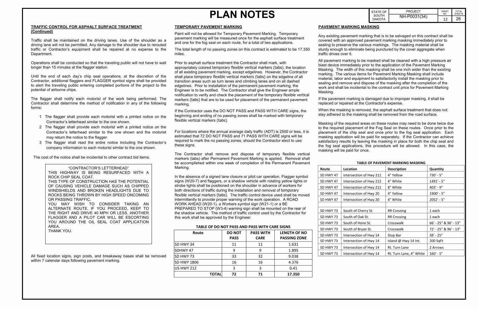
TEMPORARY PAVEMENT MARKING Paint will not be allowed for Temporary Pavement Marking. Temporary pavement marking will be measured once for the asphalt surface treatment and one for the fog seal on each route, for a total of two applications. The total length of no passing zones on this contract is estimated to be 17.350 miles. Prior to asphalt surface treatment the Contractor shall mark, with appropriately colored temporary flexible vertical markers (tabs), the location of all existing pavement marking, except edgelines. However, the Contractor shall place temporary flexible vertical markers (tabs) on the edgeline of all transition areas such as turn lanes and climbing lanes and on all dashed edgelines. Prior to installation of the permanent pavement marking, the Engineer is to be notified. The Contractor shall give the Engineer ample notification to verify and check the placement of the temporary flexible vertical
markers (tabs) that are to be used for placement of the permanent pavement marking. If the Contractor uses the DO NOT PASS and PASS WITH CARE signs, the beginning and ending of no passing zones shall be marked with temporary
flexible vertical markers (tabs). For locations where the annual average daily traffic (ADT) is 2500 or less, it is estimated that 72 DO NOT PASS and 71 PASS WITH CARE signs will be required to mark the no passing zones, should the Contractor elect to use these signs. The Contractor shall remove and dispose of temporary flexible vertical markers (tabs) after Permanent Pavement Marking is applied. Removal shall be accomplished within one week of completion of the Permanent Pavement Marking.
In the absence of a signed lane closure or pilot car operation, Flagger symbol signs (W20-7) and flaggers, or a shadow vehicle with rotating yellow lights or strobe lights shall be positioned on the shoulder in advance of workers for both directions of traffic during the installation and removal of temporary
flexible vertical markers (tabs). The traffic control device used shall be moved intermittently to provide proper warning of the work operation. A ROAD WORK AHEAD (W20-1), a Workers symbol sign (W21-1) or a BE PREPARED TO STOP (W3-4) warning sign shall be mounted on the rear of the shadow vehicle. The method of traffic control used by the Contractor for this work shall be approved by the Engineer.
TABLE OF DO NOT PASS AND PASS WITH CARE SIGNS
Route DO NOT
PASS
PASS WITH
CARE
LENGTH OF NO
PASSING ZONE
SD HWY 34 11 11 1.631
SDHWY 47 9 9 1.895
SD HWY 73 33 32 9.038
SD HWY 1806 16 16 4.376
US HWY 212 3 3 0.41
TOTAL 72 71 17.350
PAVEMENT MARKING MASKING Any existing pavement marking that is to be salvaged on this contract shall be covered with an approved pavement marking masking immediately prior to sealing to preserve the various markings. The masking material shall be sturdy enough to eliminate being punctured by the cover aggregate when traffic drives over it. All pavement marking to be masked shall be cleaned with a high pressure air blast device immediately prior to the application of the Pavement Marking Masking. The width of this masking shall be one inch wider than the existing marking. The various items for Pavement Marking Masking shall include material, labor and equipment to satisfactorily install the masking prior to sealing and remove and dispose of the masking after the completion of the work and shall be incidental to the contract unit price for Pavement Marking Masking. If the pavement marking is damaged due to improper masking, it shall be replaced or repaired at the Contractor's expense. When the masking is removed, the asphalt surface treatment that does not stay adhered to the masking shall be removed from the road surface. Masking of the required areas on these routes may need to be done twice due to the required placement of the Fog Seal on these routes. Once prior to the placement of the chip seal and once prior to the fog seal application. Each masking application will be paid for separately. If the Contractor can achieve satisfactory results by leaving the masking in place for both the chip seal and the fog seal applications, this procedure will be allowed. In this case, the masking will be paid for once.
TABLE OF PAVEMENT MARKING MASKING
Route Location Description Quantity
SD HWY 47 Intersection of Hwy 212 4" Yellow 730' - 5"
SD HWY 47 Intersection of Hwy 212 4" White 1491' - 5"
SD HWY 47 Intersection of Hwy 212 8" White 403' - 9"
SD HWY 47 Intersection of Hwy 20 4" Yellow 1900' - 5"
SD HWY 47 Intersection of Hwy 20 4" White 2052' - 5"
SD HWY 73 South of Cherry St. RR Crossing 1 each
SD HWY 73 South of Oak St. RR Crossing 1 each
SD HWY 73 South of Hone St. Crosswalk 66' - 25" & 96' - 13"
SD HWY 73 South of Bryan St. Crosswalk 72' - 25" & 96' - 13"
SD HWY 73 Intersection of Hwy 14 Stop Bar 38' - 25"
SD HWY 73 Intersection of Hwy 14 Island @ Hwy 14 Int. 200 SqFt
SD HWY 73 Intersection of Hwy 14 Rt. Turn Lane 2 Arrows
SD HWY 73 Intersection of Hwy 14 Rt. Turn Lane, 4” White 160' - 5"
“CONTRACTOR’S LETTERHEAD” THIS HIGHWAY IS BEING RESURFACED WITH A ROCK CHIP SEAL COAT. THIS TYPE OF CONSTRUCTION HAS THE POTENTIAL OF CAUSING VEHICLE DAMAGE SUCH AS CHIPPED WINDSHIELDS AND BROKEN HEADLIGHTS DUE TO ROCKS BEING THROWN BY HIGH SPEED ONCOMING OR PASSING TRAFFIC. YOU MAY WISH TO CONSIDER TAKING AN ALTERNATE ROUTE. IF YOU PROCEED, KEEP TO THE RIGHT AND DRIVE 40 MPH OR LESS. ANOTHER FLAGGER AND A PILOT CAR WILL BE ESCORTING YOU AROUND THE OIL SEAL COAT APPLICATION AREA. THANK YOU.
12

PLAN NOTES PROJECT STATE OF
SOUTH DAKOTA
NH-P0031(34)
SHEET NO.
26
TOTAL SHEETS
PERMANENT PAVEMENT MARKING PAINT All materials shall be applied as per manufacturer’s recommendations. The Contractor shall advise the Engineer a minimum of 3 weeks prior to the application of the permanent pavement marking to allow the State to check and mark the location of no passing zones. The application of permanent pavement marking paint may not begin until 7 calendar days following completion of fog seal and shall be completed within 14 days following completion of fog seal. For each working day the application of permanent pavement marking paint remains uncompleted after the 14 calendar days, the Contractor will be assessed $250 liquidated damages. This provision applies up to the Contract completion date, as extended. After the completion date, liquidated damages will be assessed in accordance with Section 8.8, until the permanent pavement marking is completed, even though the project may be open to traffic. The Contractor will be required to inventory and mark, with appropriate colored tabs, the extent and location of the existing word messages, turn arrows, stop bars, railroad crossings, pedestrian crossings, etc. before the markings are obliterated. The Engineer will be provided a copy of the pavement marking inventory.
TABLES OF PERMANENT PAVEMENT MARKING
SD 34 White Yellow 4" Yellow Dashed Centerline - 11.552 Miles @ 6.7 Gal/Mile - 78 4" Solid Yellow Centerline - 1.631 Miles @ 24.7 Gal/Mile - 41 4" Solid White Edgeline - 23.104 Miles @ 24.7 Gal/Mile 571 -
Total Gallons 571 119
SD 47 White Yellow 4" Yellow Dashed Centerline - 9.718 Miles @ 6.7 Gal/Mile - 65 4" Solid Yellow Centerline - 1.895 Miles @ 24.7 Gal/Mile - 47 4" Solid White Edgeline - 19.435 Miles @ 24.7 Gal/Mile 480 -
Total Gallons 480 112
SD73 White Yellow 4" Yellow Dashed Centerline - 13.874 Miles @ 6.7 Gal/Mile - 93 4" Solid Yellow Centerline - 9.038 Miles @ 24.7 Gal/Mile - 223 4" Solid White Edgeline - 27.748 Miles @ 24.7 Gal/Mile 665 -
Total Gallons 665 316
SD 1806 White Yellow 4" Yellow Dashed Centerline - 15.580 Miles @ 6.7 Gal/Mile - 105 4" Solid Yellow Centerline - 4.376 Miles @ 24.7 Gal/Mile - 108 4" Solid White Edgeline - 31.160 Miles @ 24.7 Gal/Mile 770 -
Total Gallons 770 213
US212 White Yellow 4" Yellow Dashed Centerline - 9.273 Miles @ 6.7 Gal/Mile - 62 4" Solid Yellow Centerline - 0.410 Miles @ 24.7 Gal/Mile - 10 4" Solid White Edgeline = 18.444 Miles @ 24.7 Gal/Mile 456 -
Total Gallons 456 72
RETROREFLECTIVITY FOR PAVEMENT MARKING PAINT The Department may take retroreflectivity readings on the pavement marking lines after 2 days and within 30 days of the line application using either a portable or mobile retroreflectometer that conforms to a 30-meter geometry. Three retroreflectivity readings will be taken on each line at each test location. The three readings will be averaged and become the reading for that test location. The readings will be taken on the edge lines and lane lines in the direction of application. For combination solid yellow and skip yellow lines for turn lanes and for centerline markings on two-way roadways, three readings will be taken in one direction, the reflectometer will be turned 180 degrees and three more readings will be taken. The six readings for the centerline markings will be averaged and become the test reading for that test location. The minimum retroreflectivity values shall be 230 mc/m
2/lux for white and 140
mc/m2/lux for yellow.
EXISTING PAVEMENT CONDITIONS AND TRAFFIC VOLUMES
The existing pavement conditions for each highway segment are listed in the table below.
ROUTE EXISTING PAVEMENT CONDITION
SD 34 – MRM 245.00+0.498 to MRM 257.06+0.000 Slightly pocked, porous and oxidized
SD 47 – MRM 189.91+0.000 to MRM 199.94+0.000 Slightly porous and oxidized
SD 73 – MRM 78.26+0.080 to MRM 92.29+0.000 Slightly porous and oxidized
SD 73 – MRM 92.29+0.000 to MRM 92.93+0.000
Slightly porous and oxidized
SD 1806 – MRM 164.43+0.000 to MRM 180.05+0.000
Slightly porous and oxidized
US 212 – MRM 245.00+0.034 to MRM 235.00+0.816 Slightly pocked, porous and oxidized
The traffic volumes are shown on the project layout sheet for each highway segment. STOCKPILE SITE RELEASES Upon completion of the contract, the Contractor shall supply the Engineer a copy of all stockpile site releases to place in the Department's file.
13
RATES OF MATERIALS AND TABLE OF ADDITIONAL QUANTITIES PROJECT STATE OF
SOUTH DAKOTA
NH-P 0031(34)
SHEET
NO.
14 26
TOTAL
SHEETS
RATES OF MATERIALS
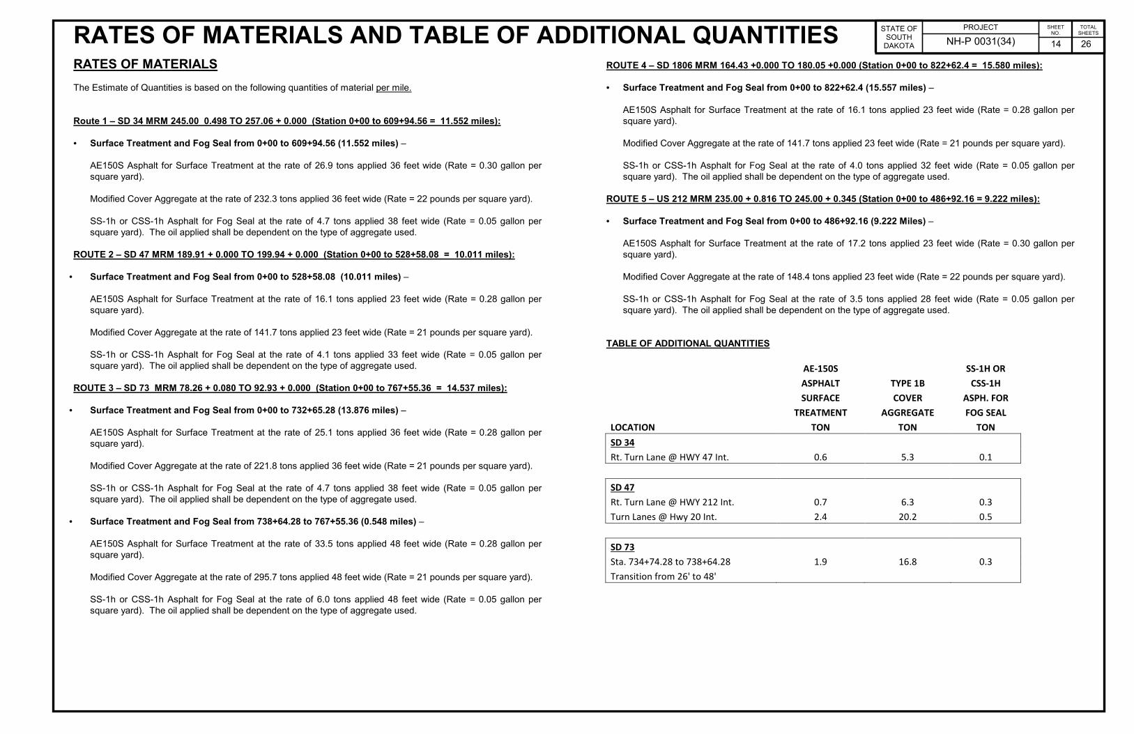
The Estimate of Quantities is based on the following quantities of material per mile.
Route 1 – SD 34 MRM 245.00 0.498 TO 257.06 + 0.000 (Station 0+00 to 609+94.56 = 11.552 miles):
• Surface Treatment and Fog Seal from 0+00 to 609+94.56 (11.552 miles) –
AE150S Asphalt for Surface Treatment at the rate of 26.9 tons applied 36 feet wide (Rate = 0.30 gallon per
square yard).
Modified Cover Aggregate at the rate of 232.3 tons applied 36 feet wide (Rate = 22 pounds per square yard).
SS-1h or CSS-1h Asphalt for Fog Seal at the rate of 4.7 tons applied 38 feet wide (Rate = 0.05 gallon per
square yard). The oil applied shall be dependent on the type of aggregate used.
ROUTE 2 – SD 47 MRM 189.91 + 0.000 TO 199.94 + 0.000 (Station 0+00 to 528+58.08 = 10.011 miles):
• Surface Treatment and Fog Seal from 0+00 to 528+58.08 (10.011 miles) –
AE150S Asphalt for Surface Treatment at the rate of 16.1 tons applied 23 feet wide (Rate = 0.28 gallon per
square yard).
Modified Cover Aggregate at the rate of 141.7 tons applied 23 feet wide (Rate = 21 pounds per square yard).
SS-1h or CSS-1h Asphalt for Fog Seal at the rate of 4.1 tons applied 33 feet wide (Rate = 0.05 gallon per
square yard). The oil applied shall be dependent on the type of aggregate used.
ROUTE 3 – SD 73 MRM 78.26 + 0.080 TO 92.93 + 0.000 (Station 0+00 to 767+55.36 = 14.537 miles):
• Surface Treatment and Fog Seal from 0+00 to 732+65.28 (13.876 miles) –
AE150S Asphalt for Surface Treatment at the rate of 25.1 tons applied 36 feet wide (Rate = 0.28 gallon per
square yard).
Modified Cover Aggregate at the rate of 221.8 tons applied 36 feet wide (Rate = 21 pounds per square yard).
SS-1h or CSS-1h Asphalt for Fog Seal at the rate of 4.7 tons applied 38 feet wide (Rate = 0.05 gallon per
square yard). The oil applied shall be dependent on the type of aggregate used.
• Surface Treatment and Fog Seal from 738+64.28 to 767+55.36 (0.548 miles) –
AE150S Asphalt for Surface Treatment at the rate of 33.5 tons applied 48 feet wide (Rate = 0.28 gallon per
square yard).
Modified Cover Aggregate at the rate of 295.7 tons applied 48 feet wide (Rate = 21 pounds per square yard).
SS-1h or CSS-1h Asphalt for Fog Seal at the rate of 6.0 tons applied 48 feet wide (Rate = 0.05 gallon per
square yard). The oil applied shall be dependent on the type of aggregate used.
ROUTE 4 – SD 1806 MRM 164.43 +0.000 TO 180.05 +0.000 (Station 0+00 to 822+62.4 = 15.580 miles):
• Surface Treatment and Fog Seal from 0+00 to 822+62.4 (15.557 miles) –
AE150S Asphalt for Surface Treatment at the rate of 16.1 tons applied 23 feet wide (Rate = 0.28 gallon per
square yard).
Modified Cover Aggregate at the rate of 141.7 tons applied 23 feet wide (Rate = 21 pounds per square yard).
SS-1h or CSS-1h Asphalt for Fog Seal at the rate of 4.0 tons applied 32 feet wide (Rate = 0.05 gallon per
square yard). The oil applied shall be dependent on the type of aggregate used.
ROUTE 5 – US 212 MRM 235.00 + 0.816 TO 245.00 + 0.345 (Station 0+00 to 486+92.16 = 9.222 miles):
• Surface Treatment and Fog Seal from 0+00 to 486+92.16 (9.222 Miles) –
AE150S Asphalt for Surface Treatment at the rate of 17.2 tons applied 23 feet wide (Rate = 0.30 gallon per
square yard).
Modified Cover Aggregate at the rate of 148.4 tons applied 23 feet wide (Rate = 22 pounds per square yard).
SS-1h or CSS-1h Asphalt for Fog Seal at the rate of 3.5 tons applied 28 feet wide (Rate = 0.05 gallon per
square yard). The oil applied shall be dependent on the type of aggregate used.
TABLE OF ADDITIONAL QUANTITIES
AE-150S SS-1H OR
ASPHALT TYPE 1B CSS-1H
SURFACE COVER ASPH. FOR
TREATMENT AGGREGATE FOG SEAL
LOCATION TON TON TON
SD 34
Rt. Turn Lane @ HWY 47 Int. 0.6 5.3 0.1
SD 47
Rt. Turn Lane @ HWY 212 Int. 0.7 6.3 0.3
Turn Lanes @ Hwy 20 Int. 2.4 20.2 0.5
SD 73
Sta. 734+74.28 to 738+64.28 1.9 16.8 0.3
Transition from 26' to 48'
Asphalt Concrete
Class Q2R Hot Mixed
1.0’ 1.0’14.0’ 14.0’
CL
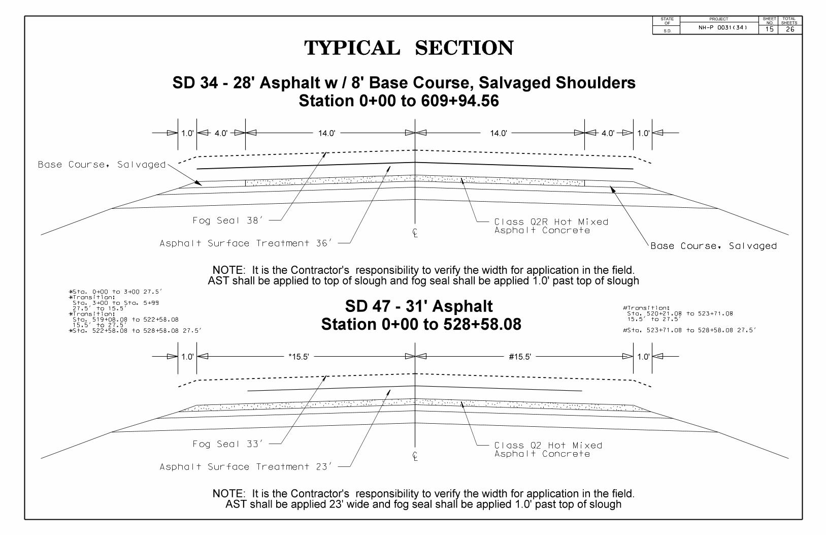
TYPICAL SECTION
1.0’ 1.0’*15.5’ #15.5’
CLAsphalt Concrete
Class Q2 Hot Mixed
Station 0+00 to 528+58.08
Fog Seal 33’
Asphalt Surface Treatment 23’
Fog Seal 38’
Asphalt Surface Treatment 36’
AST shall be applied to top of slough and fog seal shall be applied 1.0’ past top of sloughNOTE: It is the Contractor’s responsibility to verify the width for application in the field.
4.0’4.0’
SD 34 - 28’ Asphalt w / 8’ Base Course, Salvaged Shoulders
SD 47 - 31’ Asphalt
PROJECTNO. SHEETS
SHEET TOTALSTATE
S.D.
OF
Station 0+00 to 609+94.56
AST shall be applied 23’ wide and fog seal shall be applied 1.0’ past top of sloughNOTE: It is the Contractor’s responsibility to verify the width for application in the field.
*Sta. 522+58.08 to 528+58.08 27.5’
15.5’ to 27.5’
Sta. 519+08.08 to 522+58.08
*Transition:
27.5’ to 15.5’
Sta. 3+00 to Sta. 5+99
*Transition:
*Sta. 0+00 to 3+00 27.5’
#Sta. 523+71.08 to 528+58.08 27.5’
15.5’ to 27.5’
Sta. 520+21.08 to 523+71.08
#Transition:
NH-P 0031(34)
Base Course, Salvaged
Base Course, Salvaged
15 26
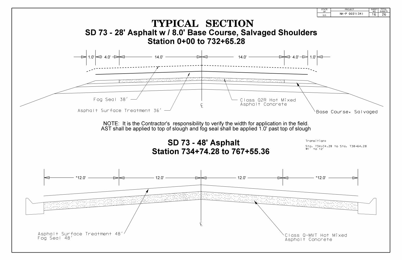
TYPICAL SECTION
Asphalt Concrete
Class Q2R Hot Mixed
1.0’ 1.0’14.0’ 14.0’
CL
Fog Seal 38’
Asphalt Surface Treatment 36’
AST shall be applied to top of slough and fog seal shall be applied 1.0’ past top of sloughNOTE: It is the Contractor’s responsibility to verify the width for application in the field.
4.0’4.0’
SD 73 - 28’ Asphalt w / 8.0’ Base Course, Salvaged Shoulders
Station 0+00 to 732+65.28
SD 73 - 48’ Asphalt
CL
12.0’*12.0’ 12.0’ *12.0’
Station 734+74.28 to 767+55.36*1’ to 12’
Sta. 734+74.28 to Sta. 738+64.28
Transition:
PROJECTNO. SHEETS
SHEET TOTALSTATE
S.D.
OF
NH-P 0031(34)
Base Course, Salvaged
Fog Seal 48’
Asphalt Surface Treatment 48’
Asphalt Concrete
Class Q-MVT Hot Mixed
16 26
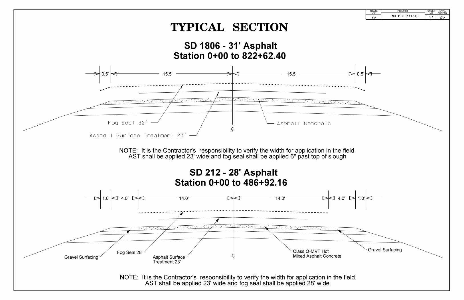
TYPICAL SECTION
0.5’ 0.5’15.5’ 15.5’
CL
Station 0+00 to 822+62.40
Fog Seal 32’
Asphalt Surface Treatment 23’
CL
Station 0+00 to 486+92.16
AST shall be applied 23’ wide and fog seal shall be applied 6" past top of sloughNOTE: It is the Contractor’s responsibility to verify the width for application in the field.
AST shall be applied 23’ wide and fog seal shall be applied 28’ wide.NOTE: It is the Contractor’s responsibility to verify the width for application in the field.
Asphalt Concrete
SD 1806 - 31’ Asphalt
SD 212 - 28’ Asphalt
1.0’ 1.0’14.0’ 14.0’ 4.0’4.0’
PROJECTNO. SHEETS
SHEET TOTALSTATE
S.D.
OF
Gravel Surfacing
Mixed Asphalt Concrete
Class Q-MVT Hot
Treatment 23’
Asphalt Surface
Fog Seal 28’
Gravel Surfacing
NH-P 0031(34) 2617

ITEMIZED LIST FOR TRAFFIC CONTROL PROJECT STATE OF
SOUTH DAKOTA
NH-P0031(34)
SHEET
18 26
TOTAL SHEETS
SD 34
SIGN
CODE SIGN DESCRIPTION NUMBER
SIGN
SIZE
SQFT
PER
SIGN
SQFT
0.000001
W8-6 TRUCK CROSSING 2 48'' x 48'' 16.0 32.0
W8-7 LOOSE GRAVEL 8 48'' x 48'' 16.0 128.0
W13-1P ADVISORY SPEED (plaque) 8 30'' x 30'' 6.3 50.4
W20-1 ROAD WORK AHEAD 4 48'' x 48'' 16.0 64.0
W20-4 ONE LANE ROAD AHEAD 4 48'' x 48'' 16.0 64.0
W20-7 FLAGGER (symbol) 4 48'' x 48'' 16.0 64.0
W21-2 FRESH OIL 2 48'' x 48'' 16.0 32.0
G20-1 ROAD WORK NEXT _12_ MILES 2 36'' x 18'' 4.5 9.0
G20-2 END ROAD WORK 3 36'' x 18'' 4.5 13.5
0.000001
CONVENTIONAL ROAD
TRAFFIC CONTROL SIGNS SQFT 456.9
SD 47
SIGN
CODE SIGN DESCRIPTION NUMBER
SIGN
SIZE
SQFT
PER
SIGN
SQFT
0.000001
W8-6 TRUCK CROSSING 2 48'' x 48'' 16.0 32.0
W8-7 LOOSE GRAVEL 9 48'' x 48'' 16.0 144.0
W13-1P ADVISORY SPEED (plaque) 9 30'' x 30'' 6.3 56.7
W20-1 ROAD WORK AHEAD 4 48'' x 48'' 16.0 64.0
W20-4 ONE LANE ROAD AHEAD 4 48'' x 48'' 16.0 64.0
W20-7 FLAGGER (symbol) 4 48'' x 48'' 16.0 64.0
W21-2 FRESH OIL 2 48'' x 48'' 16.0 32.0
G20-1 ROAD WORK NEXT _10_ MILES 2 36'' x 18'' 4.5 9.0
G20-2 END ROAD WORK 3 36'' x 18'' 4.5 13.5
0.000001
CONVENTIONAL ROAD
TRAFFIC CONTROL SIGNS SQFT 479.2
SD 73
SIGN
CODE SIGN DESCRIPTION NUMBER
SIGN
SIZE
SQFT
PER
SIGN
SQFT
0.000001
W8-6 TRUCK CROSSING 2 48'' x 48'' 16.0 32.0
W8-7 LOOSE GRAVEL 9 48'' x 48'' 16.0 144.0
W13-1P ADVISORY SPEED (plaque) 9 30'' x 30'' 6.3 56.7
W20-1 ROAD WORK AHEAD 4 48'' x 48'' 16.0 64.0
W20-4 ONE LANE ROAD AHEAD 4 48'' x 48'' 16.0 64.0
W20-7 FLAGGER (symbol) 4 48'' x 48'' 16.0 64.0
W21-2 FRESH OIL 2 48'' x 48'' 16.0 32.0
G20-1 ROAD WORK NEXT _15_ MILES 2 36'' x 18'' 4.5 9.0
G20-2 END ROAD WORK 4 36'' x 18'' 4.5 18.0
0.000001
CONVENTIONAL ROAD
TRAFFIC CONTROL SIGNS SQFT 483.7
SD 1806
SIGN
CODE SIGN DESCRIPTION NUMBER
SIGN
SIZE
SQFT
PER
SIGN
SQFT
0.000001
W8-6 TRUCK CROSSING 2 48'' x 48'' 16.0 32.0
W8-7 LOOSE GRAVEL 8 48'' x 48'' 16.0 128.0
W13-1P ADVISORY SPEED (plaque) 8 30'' x 30'' 6.3 50.4
W20-1 ROAD WORK AHEAD 4 48'' x 48'' 16.0 64.0
W20-4 ONE LANE ROAD AHEAD 4 48'' x 48'' 16.0 64.0
W20-7 FLAGGER (symbol) 4 48'' x 48'' 16.0 64.0
W21-2 FRESH OIL 2 48'' x 48'' 16.0 32.0
G20-1 ROAD WORK NEXT _16_ MILES 2 36'' x 18'' 4.5 9.0
G20-2 END ROAD WORK 2 36'' x 18'' 4.5 9.0
0.000001
CONVENTIONAL ROAD
TRAFFIC CONTROL SIGNS SQFT 452.4
US 212
SIGN
CODE SIGN DESCRIPTION NUMBER
SIGN
SIZE
SQFT
PER
SIGN
SQFT
0.000001
W8-6 TRUCK CROSSING 2 48'' x 48'' 16.0 32.0
W8-7 LOOSE GRAVEL 8 48'' x 48'' 16.0 128.0
W13-1P ADVISORY SPEED (plaque) 8 30'' x 30'' 6.3 50.4
W20-1 ROAD WORK AHEAD 4 48'' x 48'' 16.0 64.0
W20-4 ONE LANE ROAD AHEAD 4 48'' x 48'' 16.0 64.0
W20-7 FLAGGER (symbol) 4 48'' x 48'' 16.0 64.0
W21-2 FRESH OIL 2 48'' x 48'' 16.0 32.0
G20-1 ROAD WORK NEXT _10_ MILES 2 36'' x 18'' 4.5 9.0
G20-2 END ROAD WORK 2 36'' x 18'' 4.5 9.0
0.000001
CONVENTIONAL ROAD
TRAFFIC CONTROL SIGNS SQFT 452.4

PERMANENT PAVEMENT MARKING PAINT
PROJECT STATE OF SOUTH
DAKOTA
NH-P0031(34)
SHEET
19 26
TOTAL SHEETS
FURNISHING AND APPLYING PAVEMENT MARKING PAINT
UNDIVIDED ROADWAY 1. Approximate paint application rates shall be as follows:
Four Lane Roadway Two Lane Roadway(Rates for one line)
Solid Yellow Centerline Yellow CenterlineRate = 24.7 Gals./Pass-Mile (Includes No Passing Zones)
Dashed White Laneline Rate = 15± Gals./Pass-Mile
Rate = 6.7 Gals./Pass-Mile Solid White Edgeline
Solid White Edgeline (Rate for one line) (Not applicable in curb Rate = 24.7 Gals./Pass-Mile
12' 12' 12' 12' & gutter section)Rate = 24.7 Gals./Pass-Mile
2. Typical pavement marking as shown on this sheet shall beapplied throughout the entire length of undivided roadway.
3. Exact location of NO PASSING ZONE lines will be determined
30' in the field by the Engineer. A dash of white paint will mark the
beginning and end of all no passing zones. NO PASSING ZONE
10' signs and the ending post in fence lines, if present, shall not be
used as the beginning and ending of NO PASSING ZONE lines.
4. Traffic Control shall be incidental to the cost of application. The
striper and advance or trailing warning vehicle shall be equipped with flashing amber lights or advance warning arrow panel.
PAVEMENT
MARKING
PAINT
WHITE Gal.
YELLOW Gal.
TOTAL Gal.
30'
10'
11'-8" 11'-8"
PCN
05L4
2942
832
3774
ESTIMATED QUANTITIES
CAR
Y
SH
OULD
ER
SH
OULD
ER
4" YELLO
W
4" SP
AC
E
4" YELLO
W
4" W
HIT
E
4" W
HIT
E
CUR
B &
GUTTER
4"
WH
ITE
NO
TE: O
NLY D
ASH
ED
WH
ITE L
INES E
XTEN
D T
HR
OUG
H I
NTER
SEC
TIO
NS.
CAR
X
NO
PASSIN
G Z
ON
E L
INE
ZO
NE O
F L
IMIT
ED
SIG
HT
DIS
TAN
CE F
OR
CAR
Y
ZO
NE O
F L
IMIT
ED
SIG
HT
DIS
TAN
CE F
OR
CAR
X
CU
RB
& G
UTTER
4" W
HIT
E
NO
PASSIN
G Z
ON
E L
INE
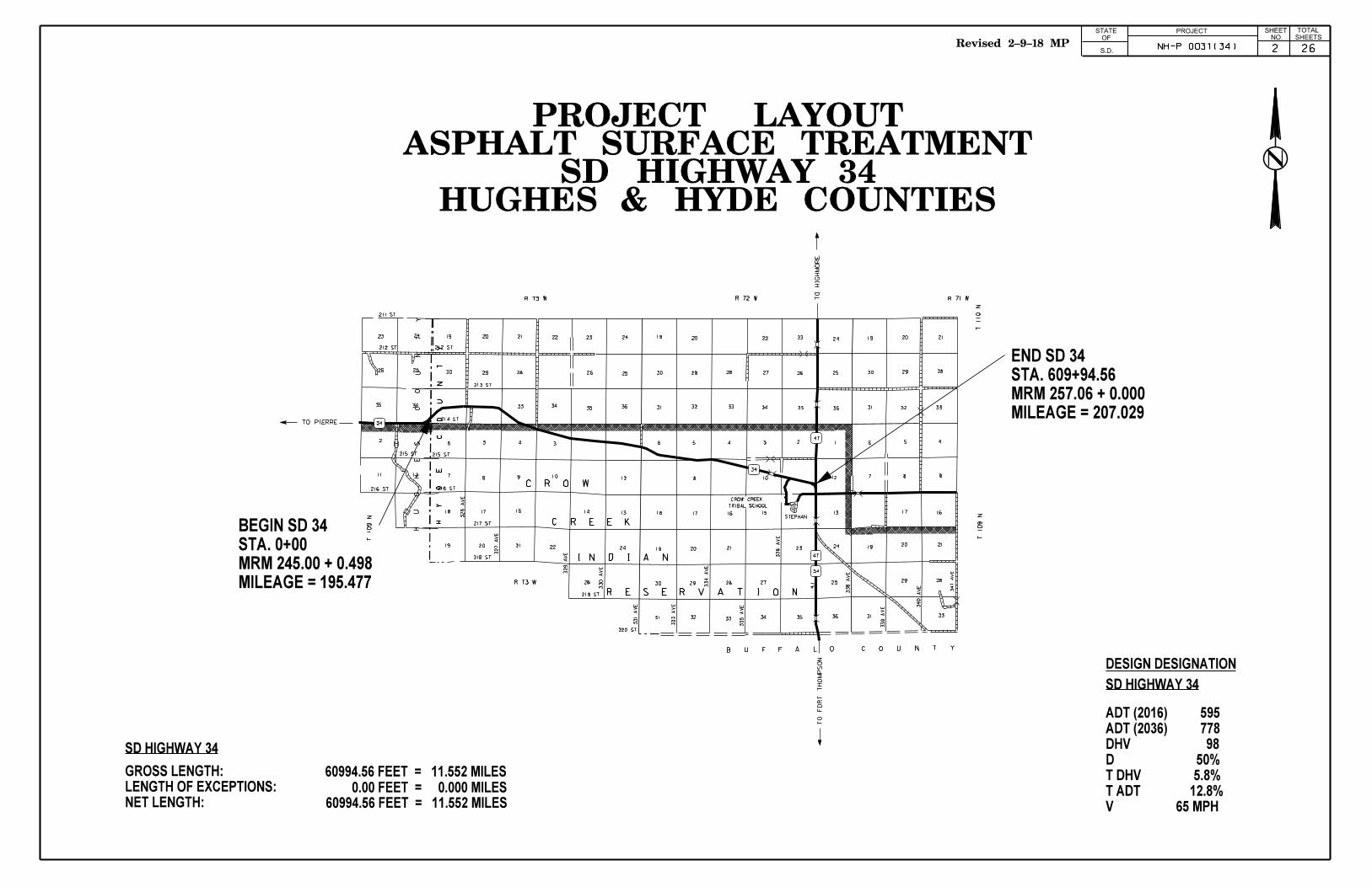
34
12
25
24
215 ST
H
Y
D
E
C
O
U
N
T
Y
19 20 21 22 23 24
2526282930
3435 36
4
78 9 10
12
18 17 16 14 13
19 20 21 22 24
26 2930
19 20
30 29 28
333231
22 23 24
27 26 25
34 35 36
19 20 21
30 29 28
31 32 33
6 4
18 17 16
19 20 21
33
28
3231
3
10 12
15 13
2324
27 25
34 35 36
2 1 6 5 4
31 33
29 28
1920 21
17 16
8 97
47
34
47
34
4.1
56
C R O W
C R E E K
I N D I A N
R E S E R V A T I O N
H
U
G
H
E S
C
O
U
N
T
Y
213 ST
214 ST
215 ST
217 ST
218 ST
219 ST
220 ST
326
AV
E
327
AV
E
329
AV
E
330
AV
E
331
AV
E
333
AV
E
334
AV
E
335
AV
E
338
AV
E
339
AV
E
340
AV
E
341
AV
E
336
AV
E
CROW CREEK
TRIBAL SCHOOL
STEPHAN
B
7 9 AB
C
B
B
B
B
B
C
A B
C
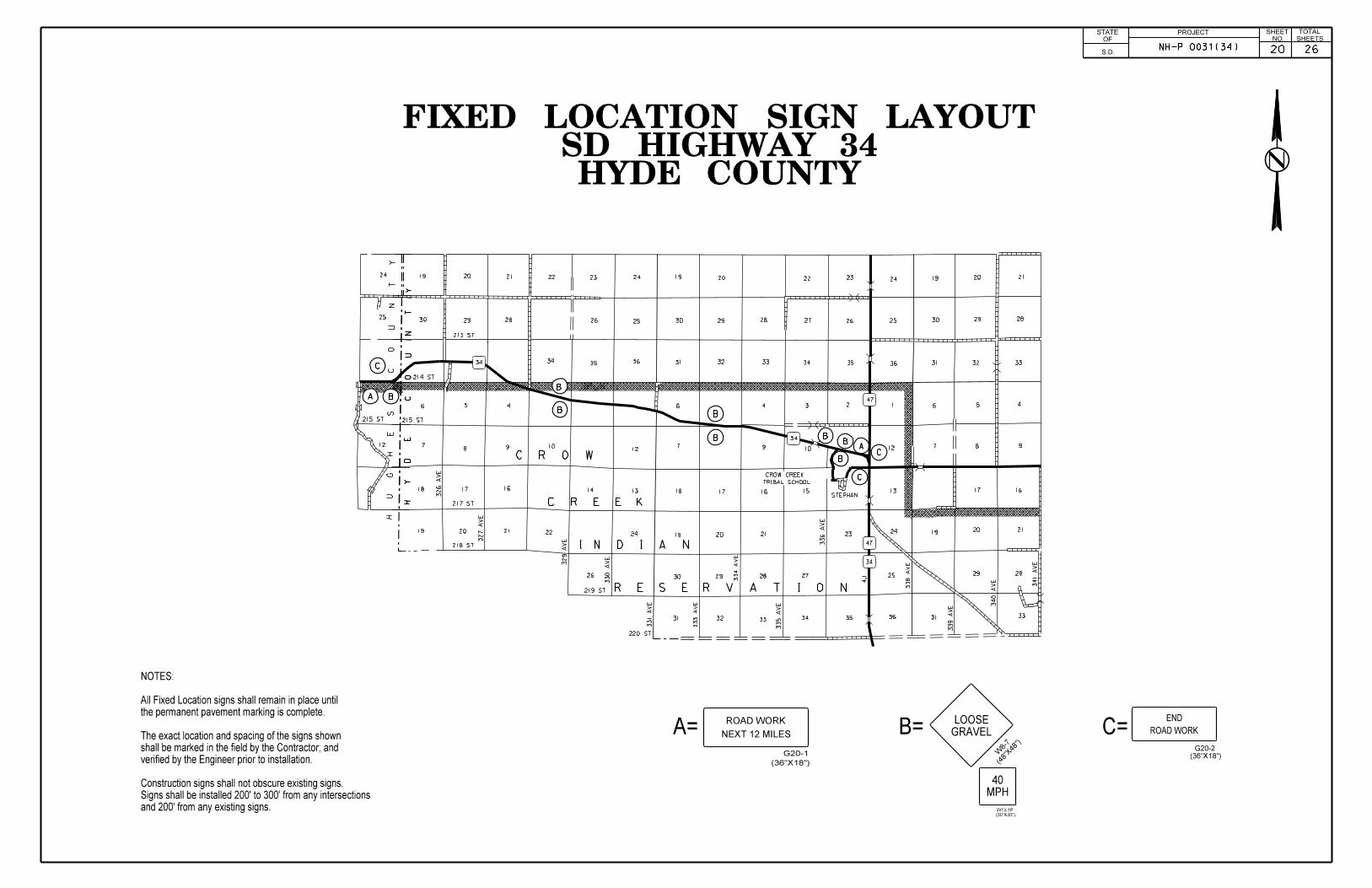
and 200’ from any existing signs.
Signs shall be installed 200’ to 300’ from any intersections
Construction signs shall not obscure existing signs.
verified by the Engineer prior to installation.
shall be marked in the field by the Contractor; and
The exact location and spacing of the signs shown
the permanent pavement marking is complete.
All Fixed Location signs shall remain in place until
NOTES:
G20-2
ROAD WORK
A=
(36"X18")
G20-1
NEXT 12 MILES C=END
ROAD WORK
(36"X18")
B=
(48"
X48")
GRAVEL
LOOSE
W8-7
PROJECTNO. SHEETS
SHEET TOTALSTATE
S.D.
OF
HYDE COUNTYSD HIGHWAY 34
FIXED LOCATION SIGN LAYOUT
(30"X30")
W13-1P
MPH
40
NH-P 0031(34) 2620
20
LE
BA
NO
N
HO
VE
N
20
47
20
47
47
212
314 AVE
315 AVE
316 AVE
317 AVE
318 AVE
320 AVE
321 AVE
322 AVE
PO
P. 4
06
PO
P. 4
7
13
14
15
12
11
103
21
36
35
3427
26
2524
23
2215
14
13
12
11
103
2136
35
34
27
26
2524
23
22
15
14
13
12
11
103
21
23
6 78
910
11
14
15
18
19
20
21
22
23
26
27
28
29
30
31
34
35
34
56 7
810
11
14
15
18
23
21
20
19
26
27
30
31
32
33
35
23
6 78
910
11
14
15
16
17
18
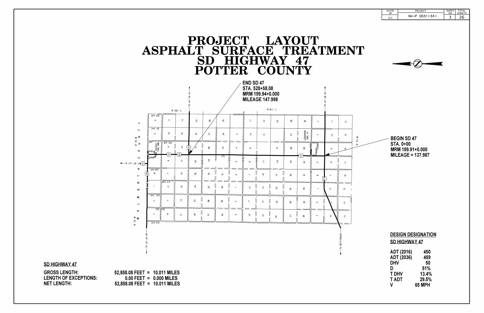
0.7
BA
C
B C
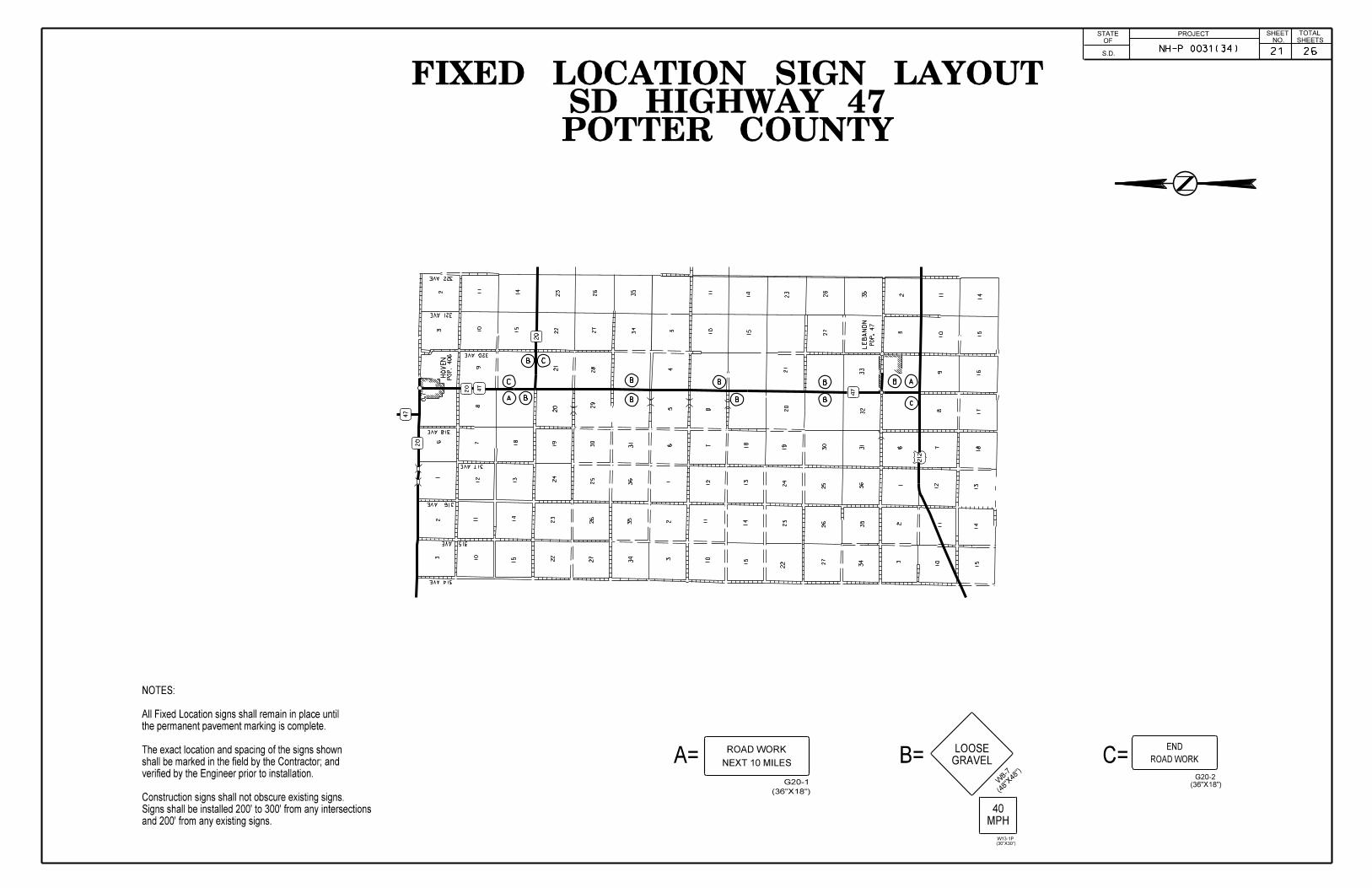
POTTER COUNTYSD HIGHWAY 47
FIXED LOCATION SIGN LAYOUT
and 200’ from any existing signs.
Signs shall be installed 200’ to 300’ from any intersections
Construction signs shall not obscure existing signs.
verified by the Engineer prior to installation.
shall be marked in the field by the Contractor; and
The exact location and spacing of the signs shown
the permanent pavement marking is complete.
All Fixed Location signs shall remain in place until
NOTES:
G20-2
ROAD WORK
A=
(36"X18")
G20-1
NEXT 10 MILES C=END
ROAD WORK
(36"X18")
B=
(48"
X48")
GRAVEL
LOOSE
W8-7
A
PROJECTNO. SHEETS
SHEET TOTALSTATE
S.D.
OF
B
B
B
B
B
B
B
C
(30"X30")
W13-1P
MPH
40
NH-P 0031(34) 21 26
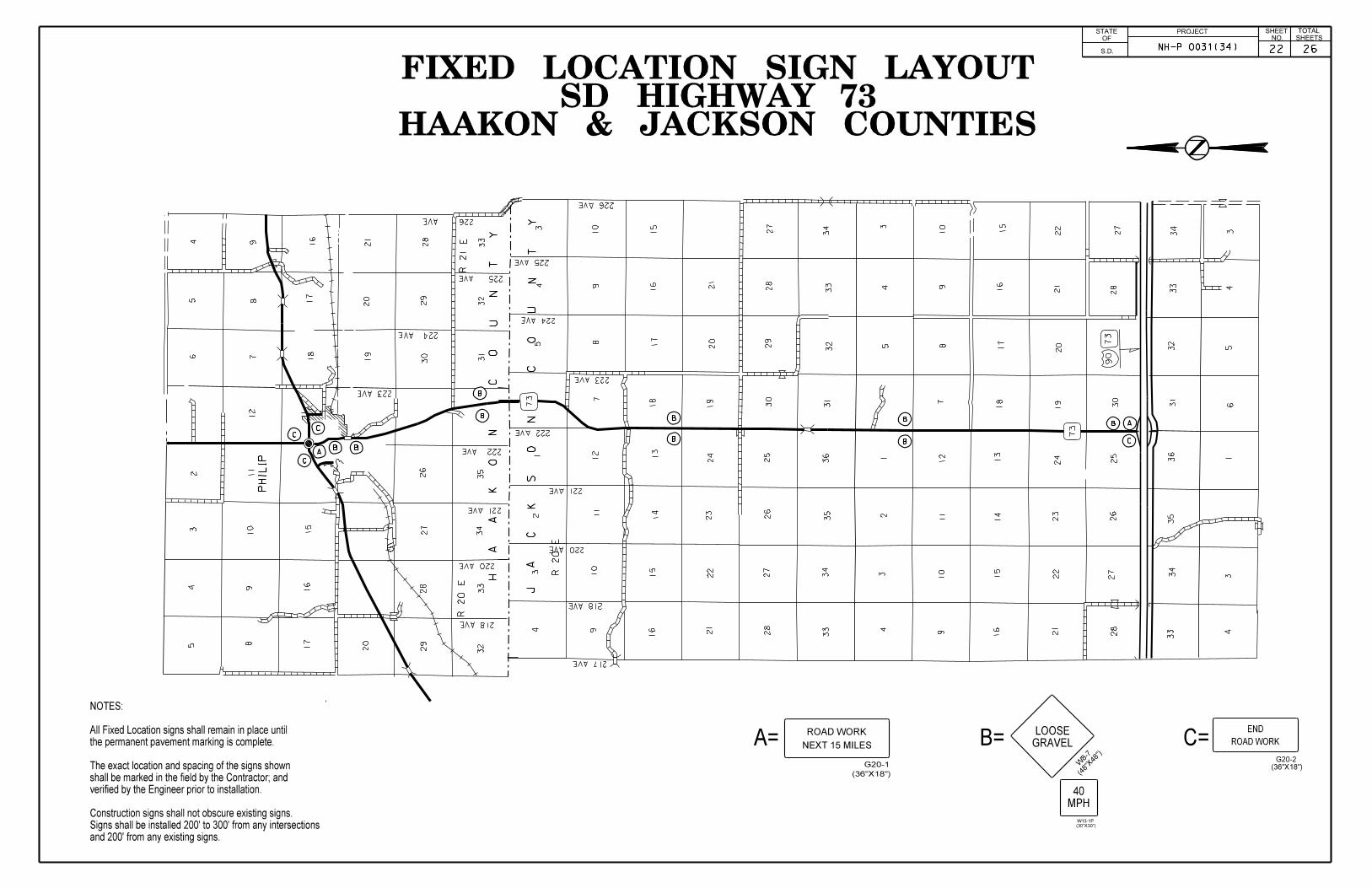
C
HAAKON & JACKSON COUNTIESSD HIGHWAY 73
FIXED LOCATION SIGN LAYOUT
G20-2
ROAD WORK
A=
(36"X18")
G20-1
NEXT 15 MILES C=END
ROAD WORK
(36"X18")
B=
(48"
X48")
GRAVEL
LOOSE
W8-7
PHILIP
J
A
C
K S
O
N
C
O
U
N
T
Y
R 20
E
218 AVE
220 AVE
221 AVE
222 AVE
223 AVE
224 AVE
225 AVE
226 AVE
73
73
H
A
A
K
O
N
C
O
U
N
T
Y
R 20
ER 21 E
217 AVE
218 AVE
220 AVE
221 AVE
222 AVE
223 AVE
224 AVE
225 AVE
226 AVE
90
73
54
32
89
10
11
12
15
16
17
20
26
27
28
29
32
33
34
35
65
4
78
9 16
17
18
19
20
21
28
29
30 31
32
33
10
103
45
78
9
15
16
17
18
19
20
21
27
28
29
30
31
32
33
34 3
45
78
9
15
16
17
18
19
20
21
22
27
28
30
31
32
33
34
34
56
1 1 1
10
10
23
4 911
12 13
14
15
16 21
22
23
24
25
26
27
28
33
34
35
36
23
4 911
12 13
14
15
16 21
22
23
24
25
26
27
28
33
34
35
36
34
and 200’ from any existing signs.
Signs shall be installed 200’ to 300’ from any intersections
Construction signs shall not obscure existing signs.
verified by the Engineer prior to installation.
shall be marked in the field by the Contractor; and
The exact location and spacing of the signs shown
the permanent pavement marking is complete.
All Fixed Location signs shall remain in place until
NOTES:
A
AB B
PROJECTNO. SHEETS
SHEET TOTALSTATE
S.D.
OF
C
B
C
C
B
B
B
B
B
B
MPH
40
(30"X30")
W13-1P
NH-P 0031(34) 2622

456
7 8 9 10 11 12
131415161718
19 20 22 23 24
252627282930
31 32 33 34 35 36
123456
7 8 9 10 11 12
131415161718
19 20 21 22 23 24
252627282930
31 32 33 34 35 36
78
1415161718
20 21 22
27282930
31 33 34
1235
8 10 11 12
13141517
20 22 23 24
2526272829
32 33 34 35 36
19
24232220
19
18 1716
242322
15 14 13
987
19
17 1613
12
14
11
23
83
83
1806
L O W E R B R U L E
I N D I A N R E S E R V A T I O N
290
AV
E
291
AV
E
292
AV
E
293
AV
E
294
AV
E
295
AV
E
296
AV
E
297
AV
E
299
AV
E
300
AV
E
301
AV
E
302
AV
E
303
AV
E
304
AV
E
305
AV
E
306
AV
E
307
AV
E
308
AV
E
309
AV
E
310
AV
E
311
AV
E
312
AV
E
293
AV
E
291
AV
E
290
AV
E
288
AV
E
294
AV
E
296
AV
E
297
AV
E
299
AV
E
300
AV
E
301
AV
E
305
AV
E
306
AV
E
307
AV
E
308
AV
E
216 ST
219 ST
220 ST
221 ST
1806
STANLEY COUNTYSD HIGHWAY 1806
FIXED SIGN LOCATION LAYOUT
and 200’ from any existing signs.
Signs shall be installed 200’ to 300’ from any intersections
Construction signs shall not obscure existing signs.
verified by the Engineer prior to installation.
shall be marked in the field by the Contractor; and
The exact location and spacing of the signs shown
the permanent pavement marking is complete.
All Fixed Location signs shall remain in place until
NOTES:
A
G20-2
ROAD WORK
A=
(36"X18")
G20-1
NEXT 16 MILES C=END
ROAD WORK
(36"X18")
B=
(48"
X48")
GRAVEL
LOOSE
W8-7
A
PROJECTNO. SHEETS
SHEET TOTALSTATE
S.D.
OF
B
C
B
C
B
B
B
B
B
B
MPH
40
(30"X30")
W13-1P
NH-P 0031(34) 23 26

LEBANON
13141517
24232120
2526272829
32 3335 36
1235
8 9 10 11 12
1314151617
20 21 22 23 24
252627282930 29 28 27 26 25
19 20 21 22 23 24
18 17 16 15 14 13
121110987
6 5 4 3 2 1
363534333231
30 29 28 27 26 25
242322212019
18 17 16 15 14 13
47 212
47
T 119
N
F
A
U
L
K
C
O
U
N
T
Y
R 73 W
156 ST
157 ST
158 ST
159 ST
160 ST
162 ST
163 ST
164 ST
165 ST
POP. 47
R 74 W
POTTER COUNTYUS HIGHWAY 212
FIXED LOCATION SIGN LAYOUT
and 200’ from any existing signs.
Signs shall be installed 200’ to 300’ from any intersections
Construction signs shall not obscure existing signs.
verified by the Engineer prior to installation.
shall be marked in the field by the Contractor; and
The exact location and spacing of the signs shown
the permanent pavement marking is complete.
All Fixed Location signs shall remain in place until
NOTES:
G20-2
ROAD WORK
A=
(36"X18")
G20-1
NEXT 10 MILES C=END
ROAD WORK
(36"X18")
B=
(48"
X48")
GRAVEL
LOOSE
W8-7
A
BA
B
B
B
B
B
B
PROJECTNO.
SHEET TOTALSTATE
S.D.
OF
B
C
C
26
(30"X30")
W13-1P
MPH
40
NH-P 0031(34) 2624
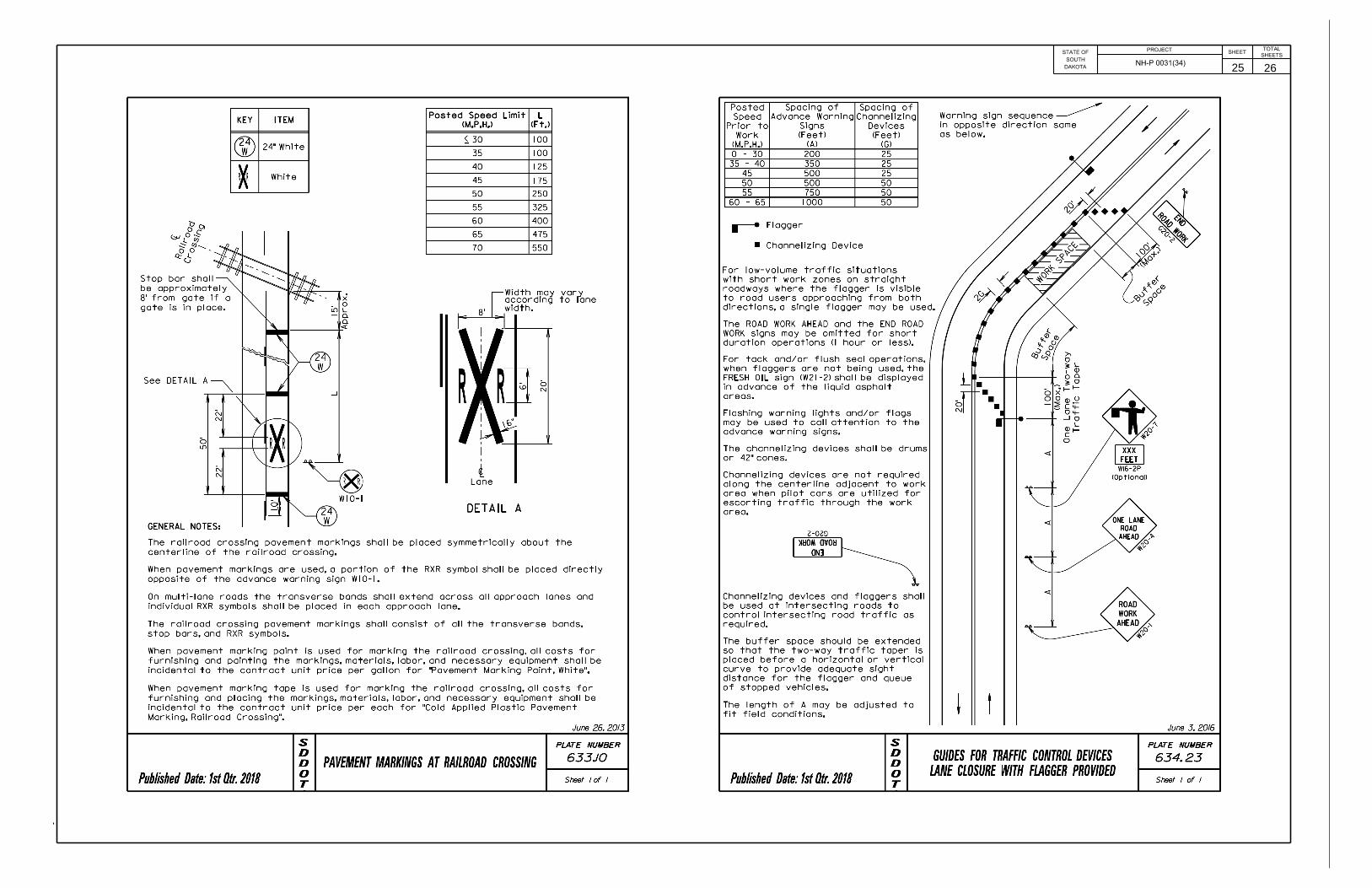
DAKOTA
SOUTH
STATE OFPROJECT
SHEETSHEETS
TOTAL
NH-P 0031(34) 25 26
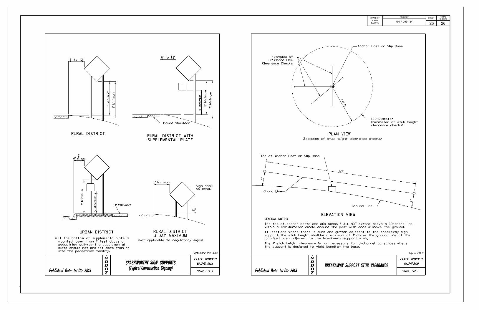
DAKOTA
SOUTH
STATE OFPROJECT
SHEETSHEETS
TOTAL
NH-P 0031(34) 26 26