STANDARD SIZES OF CARBON AND CARBON MANGANESE …
17
Gas Industry Standard GIS/DAT6: 2019 Specification for STANDARD SIZES OF CARBON AND CARBON MANGANESE STEEL PIPE FOR OPERATING PRESSURES GREATER THAN 7 BAR Use of these company logos only indicates membership of the ENA and does not imply that individual organisations have adopted either fully or in part the content of this document. Reference should be made to individual organisations to establish extent of adoption and any caveats or deviations.
Transcript of STANDARD SIZES OF CARBON AND CARBON MANGANESE …

Gas Industry Standard
GIS/DAT6: 2019
Specification for STANDARD SIZES OF CARBON AND CARBON MANGANESE STEEL PIPE FOR OPERATING PRESSURES GREATER THAN 7 BAR
Use of these company logos only indicates membership of the ENA and does not imply that individual organisations have adopted either fully or in part the content of this document. Reference should be made to individual organisations to establish extent of adoption and any caveats or deviations.


i
Contents Foreword ii Mandatory and non-mandatory requirements ii Disclaimer ii Brief history iii 1. Scope 5 2. Normative references 5 3. Terms and Definitions 6 4. Conformance 6 5. Pipe Data Sources 6 6. General Information 6 7. API Standards 7
Historical Pipe Data 12

GIS/DAT6:2019
ii
Foreword Gas Industry Standards (GIS) are revised, when necessary, by the issue of new editions. Users should ensure that they are in possession of the latest edition. Contractors and other users external to Gas Transporters should direct their requests for copies of a GIS to the department or group responsible for the initial issue of their contract documentation. Comments and queries regarding the technical content of this document should be directed in the first instance to the contract department of the Gas Transporter responsible for the initial issue of their contract documentation. This standard calls for the use of procedures that may be injurious to health if adequate precautions are not taken. It refers only to technical suitability and does not absolve the user from legal obligations relating to health and safety at any stage. Compliance with this engineering document does not confer immunity from prosecution for breach of statutory or other legal obligations.
Mandatory and non-mandatory requirements For the purposes of a GIS the following auxiliary verbs have the meanings indicated: can indicates a physical possibility; may indicates an option that is not mandatory; shall indicates a GIS requirement; should indicates best practice and is the preferred option. If an alternative method is used then a suitable and sufficient risk assessment needs to be completed to show that the alternative method delivers the same, or better, level of protection.
Disclaimer This engineering document is provided for use by Gas Transporters and such of their contractors as are obliged by the terms of their contracts to comply with this engineering document. Where this engineering document is used by any other party, it is the responsibility of that party to ensure that the engineering document is correctly applied.

GIS/DAT6:2019
iii
Brief history
First published as BG/PS/DAT6 1970 Second update published as BG/PS/DAT6 Third update published as GBE/DAT6
1988 February 1994
Fourth update published as T/SP/DAT/6 October 2003 Editorial update to comply with GRM August 2004 Revised and re-issued as SGN/SP/DAT/6 December 2011 Revised and re-issued as SGN/SP/DAT/6 December 2016 Reviewed, updated and published as a Gas Industry Standard
March 2019
© ENA, on behalf of Cadent Gas Limited, Gas Networks Ireland, National Grid, Northern Gas Networks, SGN, and Wales & West Utilities. This Gas Industry Standard is copyright and must not be reproduced in whole or in part by any means without the approval in writing of either Cadent Gas Limited, Gas Networks Ireland, National Grid, Northern Gas Networks, SGN, or Wales & West Utilities.

GIS/DAT6:2019
iv
GIS/DAT6:2019
5
1. Scope
This Gas Industry Standard gives details of standard dimensions, material grades and pressures for specific design factors for carbon and carbon manganese steel pipe for operating pressures greater than 7 bar.
The dimensions, materials and pressures given in this Standard are intended to provide general guidance for operating temperatures between -20 °C and +60 °C. The limiting operating condition for each pipe must be determined with reference to the design specification appropriate for the application concerned.
2. Normative references The following referenced documents are indispensable for the application of this document. For dated references, only the edition cited applies. For undated references, the latest edition of the referenced document (including any amendments) applies.
British and European standards BS EN ISO 3183, Petroleum and natural gas industries. Steel pipes for pipelines transportation systems
ISO 4200, International Standard – Plain end steel tubes, welded and seamless – General tables of dimensions and masses per unit length. BS EN 10208-2, Steel pipes for pipelines for combustible fluids - Technical delivery conditions Part 2: Pipes of requirement class B (superseded).
BS EN 10220, Seamless and welded steel tubes. Dimensions and masses per unit length.
Institution of Gas Engineers and Managers Standards IGEM/TD/1, Steel pipelines and associated installations for high-pressure gas transmission. IGE/TD/12, Pipework stress analysis for gas industry plant.
IGEM/TD/13, Pressure Regulating Installations for transmission and distribution systems.
American Petroleum Institute (API) Standard API 5L, API Specification 5L – Specification for line pipe.
Gas Transporter Specifications and former standards BG/PS/DAT6:1998, British Gas Engineering Standard Data sheet, Carbon and Carbon Manganese steel pipe for operating pressure greater than 7 bar. Earliest version of DAT/6 issued in January 1988.
BGSE/DAT6:1994, British Gas Engineering Data sheet, Carbon and Carbon Manganese steel pipe for operating pressure greater than 7 bar. Version of DAT/6 issued in 1994. DAT/23:June 1993, Gas Business Engineering Data Sheet – Carbon steel pipe of nominal diameter size 15mm, 20mm and 25mm.
T/SP/DAT6:2004, Transco version of specification DAT/6 issued in 2004. LX1: September 1993, Gas Business Engineering – Technical Specification for Submerged- arc welded pipe 400mm to 1400mm inclusive nominal size for operating pressures greater than 7 bar.
LX4: April 1993, Gas Business Engineering – Technical Specification for Seamless pipe 150mm to 450mm inclusive nominal size for operating pressures greater than 7 bar. LX5: September 1993, Gas Business Engineering – Technical Specification for Electric- Welded pipe 150mm to 450mm inclusive nominal size for operating pressures greater than 7 bar.
GIS/DAT6:2019
6
NOTE Where no date is shown, the latest edition of each standard and specification shall apply.
• Gas Transporters will each have their own specifications normally in the referenced format */SP/XX/No, where * is replaced by the Gas Transporters reference e.g. T for National Grid, or SGN, WWU etc. followed by the specification initials and number reference.
3. Terms and Definitions For the purposes of this document, the following definitions apply.
DAT6 This term has been used to refer to all versions of the specifications e.g. BGES/DAT/6*/SP/DAT/6.
Yield stress The stress level at which a metal or other material ceases to behave elastically
Material grade Classification of Steel pipe by its composition and physical properties
Design factor Stress safety factor used in pipe wall thickness calculations.
4. Conformance
Units of measurement In this standard, for data expressed in both SI and USC units, a dot (on the line) is used as the decimal separator, and no comma or space is used as the thousands separator, in order to be consistent with other Gas Transporter specifications.
5. Pipe Data Sources
Table 1
The values of minimum wall thickness used to calculate the pressures given in Tables 2a and 2b are the nominal wall thickness values given in the table, minus the relevant under-thickness tolerances specified in Table M4 of BS EN ISO 3183 and reproduced in Table 1.
Tables 2a and 2b
New Pipe data contained in tables 2a and 2b has been sourced from table 2 of ISO 4200. This table generally matches pipe data tables in BS EN 10208-1, BS EN 10208-2 (now withdrawn) and BS EN 10220. This data provides modern, metric and European data.
Historical pipe data
Data relating to earlier versions of DAT/6 is provided in Annex A, some pipe manufacturers may still be willing to provide pipes to these requirements.
6. General Information
The values of design factor (f) used in Tables 2 and C2 are the maximum values specified for various applications of pipe in IGEM/TD/1, IGE/TD/12, and IGEM/TD/13.

GIS/DAT6:2019
7
The values of pressure P (in bar) given in Table 2.
P = 20 f t s D
Where f = design factor t = minimum wall thickness of the pipe (in mm). s = specified minimum yield stress of the pipe (in MPa or N/mm2) D = outside diameter of the pipe (in mm) as given in Table 2. The pressure data given under the various design factor columns in Tables 2 and C2 should be taken as indicative only. It is supplied to provide initial pressure / duty pipe selection advice. It is the responsibility of the system designer to confirm final material selection by appropriate calculations combined with any other influences upon the design. These values apply to operating temperatures between -20 °C and +60 °C. For higher temperatures, reference should be made to the design standard appropriate for the application concerned.
The probability of minimum wall thickness and minimum yield stress occurring together is regarded as small. In the majority of applications therefore, the actual pressures for each design factor will be greater than the values given in Tables 2a and 2b.
Each size of pipe given in Table 2a and 2b may be identified by stating the nominal wall thickness and either the nominal size or outside diameter.
Approximately equivalent API 5L pipe grades, based on yield strength, corresponding to those of ISO 3183 are included in Tables 2a and 2b.
7. API Standards The following statement has been taken from the American Petroleum website. “The American Petroleum Institute specification API 5L addresses seamless and welded steel line pipe for pipeline transportation systems in the petroleum and natural gas industries. API 5L is suitable for conveying gas, water, and oil.
Specifications for API 5L adhere to the International Organization for Standardization ISO 3183, standardizing pipeline transportation systems within the materials, equipment and offshore structures for natural gas, petroleum, and petrochemical industries. When authoring the standards, the technical committee recognized that there are two basic Product Specifications Levels (PSL) of technical requirements and therefore developed PSL 1 and PSL 2. PSL 1 is a standard quality for line pipe where PSL 2 contains additional chemical, mechanical properties, and testing requirements.
Grades covered by this specification are A25, A, B and "X" Grades X42, X46, X52, X56, X60, X65, X70, and X80. The two digit number following the "X" indicates the Minimum Yield Strength (in 000's psi) of pipe produced to this grade”.

GIS/DAT6:2019
8
Table 1 - Tolerances on Wall Thickness (from table M4 of BS EN ISO 3183)
Wall Thickness t mm Permissible Tolerance - mm
Seamless Pipe:
≤ 4 +0.6mm / -0.5mm
> 4 to 25 +15% t / - 12.5% t
≥ 25 + 3.7mm or + 10% t, whichever is the greater - 3.0mm or - 10% t, whichever is the greater
Welded Pipe:
≤ 5 ± 0.5mm
˃5 to 10 ± 10% t
˃10 to ˂15 + 10% t / -5% t
˃15 to ˂20 +1.5mm / – 5% t
≥ 20 + 1.5mm / -1.0mm
GIS/DAT6:2019
9
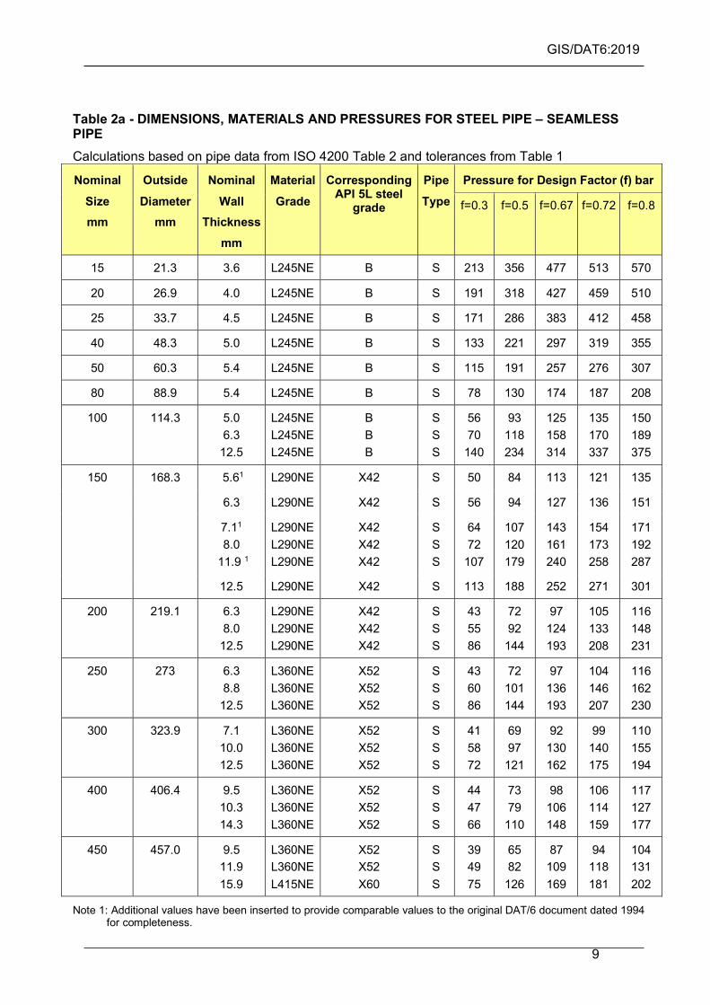
Table 2a - DIMENSIONS, MATERIALS AND PRESSURES FOR STEEL PIPE – SEAMLESS PIPE Calculations based on pipe data from ISO 4200 Table 2 and tolerances from Table 1
Nominal Size mm
Outside Diameter
mm
Nominal Wall
Thickness mm
Material Grade
Corresponding API 5L steel
grade
Pipe Type
Pressure for Design Factor (f) bar
f=0.3 f=0.5 f=0.67 f=0.72 f=0.8
15 21.3 3.6 L245NE B S 213 356 477 513 570
20 26.9 4.0 L245NE B S 191 318 427 459 510
25 33.7 4.5 L245NE B S 171 286 383 412 458
40 48.3 5.0 L245NE B S 133 221 297 319 355
50 60.3 5.4 L245NE B S 115 191 257 276 307
80 88.9 5.4 L245NE B S 78 130 174 187 208
100 114.3 5.0 6.3
12.5
L245NE L245NE L245NE
B B B
S S S
56 70
140
93 118 234
125 158 314
135 170 337
150 189 375
150 168.3 5.61 L290NE X42 S 50 84 113 121 135
6.3 L290NE X42 S 56 94 127 136 151
7.11 8.0
11.9 1
L290NE L290NE L290NE
X42 X42 X42
S S S
64 72
107
107 120 179
143 161 240
154 173 258
171 192 287
12.5 L290NE X42 S 113 188 252 271 301
200 219.1 6.3 8.0
12.5
L290NE L290NE L290NE
X42 X42 X42
S S S
43 55 86
72 92
144
97 124 193
105 133 208
116 148 231
250 273 6.3 8.8
12.5
L360NE L360NE L360NE
X52 X52 X52
S S S
43 60 86
72 101 144
97 136 193
104 146 207
116 162 230
300 323.9 7.1 10.0 12.5
L360NE L360NE L360NE
X52 X52 X52
S S S
41 58 72
69 97
121
92 130 162
99 140 175
110 155 194
400 406.4 9.5 10.3 14.3
L360NE L360NE L360NE
X52 X52 X52
S S S
44 47 66
73 79
110
98 106 148
106 114 159
117 127 177
450 457.0 9.5 11.9 15.9
L360NE L360NE L415NE
X52 X52 X60
S S S
39 49 75
65 82
126
87 109 169
94 118 181
104 131 202
Note 1: Additional values have been inserted to provide comparable values to the original DAT/6 document dated 1994 for completeness.

GIS/DAT6:2019
10
TABLE 2b - DIMENSIONS, MATERIALS AND PRESSURES FOR STEEL PIPE – SEAM WELDED PIPE Calculations based on pipe data from ISO 4200 Table 2 and tolerances from Table 1
Nominal Size mm
Outside Diameter
mm
Nominal Wall
Thickness mm
Material Grade
Corresponding API 5L steel
grade
Pipe Type
Pressure for Design Factor (f) bar
f=0.3
f=0.5
f=0.67
f=0.72
f=0.8
150 168.3 5.6 7.1
12.5
L290ME L290ME L290ME
X42 X42 X42
HFW HFW HFW
48 64
122
80 106 204
108 143 274
116 153 294
129 170 327
200 219.1 6.3 8.0
12.5
L290ME L290ME L290ME
X42 X42 X42
HFW HFW HFW
42 56 94
71 93
157
95 125 210
102 135 226
114 150 251
250 273 6.3 8.8
12.5
L360ME L360ME L360ME
X52 X52 X52
HFW HFW HFW
42 62 93
71 104 156
95 139 209
102 150 225
113 166 250
300 323.9 7.1 10.0 12.5
L360ME L360ME L360ME
X52 X52 X52
HFW HFW HFW
41 60 79
68 101 131
92 135 176
99 145 190
110 161 211
12.52 L415ME X60 HFW 91 152 203 219 243
400 406.4 8.8 10.0 14.2
L360ME L360ME L360ME
X52 X52 X52
HFW/L/H HFW/L/H HFW/L/H
41 47 71
69 79
119
93 106 160
100 114 172
111 127 191
14.22 L450ME X65 HFW/L/H 89 149 200 215 238
450 457 10.0 12.5 16.0
L360ME L360ME L415ME
X52 X52 X60
HFW/L/H HFW/L/H HFW/L/H
43 56 82
71 93
138
96 125 184
103 134 198
114 149 220
600 610 10.0 14.2 20.0
L360ME L360ME L415ME
X52 X52 X60
L/H L/H L/H
32 47 77
53 79
129
71 106 173
77 114 186
85 127 206
750 762 12.5 16.0 20.0 22.2
L360ME L415ME L415ME L415ME
X52 X60 X60 X60
L/H L/H L/H L
33 49 62 69
56 82
103 115
75 110 138 154
80 119 149 166
89 132 165 184
900
914 914
12.5 16.0 20.0 25.0
L415ME L450ME L415ME L450ME
X60 X65 X60 X65
L/H L/H L/H L
32 44 51 70
53 74 86
118
72 100 115 158
77 107 124 170
86 119 138 189
1050 1067 14.2 17.5 20.0 28.0
L415ME L450ME L450ME L450ME
X60 X65 X65 X65
L/H L/H L/H L/H
31 42 48 68
52 70 80
113
70 93
107 152
75 100 115 163
83 112 128 182

GIS/DAT6:2019
11
Nominal Size mm
Outside Diameter
mm
Nominal Wall
Thickness mm
Material Grade
Corresponding API 5L steel
grade
Pipe Type
Pressure for Design Factor (f) bar
f=0.3
f=0.5
f=0.67
f=0.72
f=0.8
1200 1219 16.0 20.0 22.2 25.0 16.0 20.0 22.2 25.0
L450ME L450ME L450ME L450ME L555ME L555ME L555ME L555ME
X65 X65 X65 X65 X80 X80 X80 X80
L/H L/H L L L L L L
33 42 46 53 41 51 57 65
56 70 78 88 69 86 96
109
75 93
104 118 92
115 129 146
80 101 112 127 99
124 138 157
89 112 125 141 110 138 154 174
16.0 L555ME X80 L 35 59 79 85 94
20.0 L555ME X80 L 44 74 99 106 118
14002 1422 22.2 L555ME X80 L 49 82 110 119 132
25.0 L555ME X80 L 56 93 125 134 149
Note 1: Additional values have been inserted to provide comparable values to the original DAT/6 document dated 1994 for completeness.
Note 2: Two additional values have been added to this table:
1) 300mm L415ME X60 pipe with a wall thickness of 12.7mm.
2) 400mm L450ME X65 pipe with a wall thickness of 14.3mm
Note 3: Pipe Types:
L = Submerged Arc Welded Longitudinal Seam
H = Submerged Arc Welded Helical Seam
HFW = High Frequency Welded

GIS/DAT6:2019
12
Historical Pipe Data
A.1 The values of minimum wall thickness used to calculate the pressures given in TableC2a and C2b are the nominal wall thickness values given in the table, minus the relevant under-thickness tolerances specified in Table 10 of BS EN 10208-2 and reproduced in Table C1.
A.2 Pipe data contained in tables C2a and C2b has been largely sourced from earlier versions of DAT/6 e.g. BG/PS/DAT/6:1988, BGES/DAT6:1994 both of which relied upon data from DAT/23, LX1, LX4 and LX5. These data values generally match those contained in Table 1 of TS-C4GAS-PIPO and API-5L Appendix E. Values contained in ASME B36.10M are broadly equivalent to those shown in Tables 2a and 2b if allowance is made for rounding of values.
A.3 Seamless pipe values for 150mm contained in earlier versions of DAT/6 differ to those provide in T/SP/DAT/6 and subsequent revisions. For completeness these values have been reinserted in this standard.
A.4 Seamless Pipe values 400 and 450mm provided in earlier versions of DAT/6 and subsequently omitted in recent DAT/6 versions have been included in this revision in table 2a.
A.5 The values of specified minimum yield stress used to calculate the pressures given in Table C2a and C2b are given in BS EN 10208-2.
Table C1 - Tolerances on Wall Thickness (from table 10 of BS EN 10208-2)
Wall Thickness t mm Permissible Tolerance
Seamless Pipe:
t ≤ 4 +0.6 mm / -0.5 mm
4< t < 25 +15 % t / - 12.5 % t
t ≥ 25 + 3.75mm or +10% t/ - 3.0 mm or + / - 10% t (whichever is the greater)
Welded Pipe:
t ≤ 10 +1.0 mm / -0.5 mm
10 < t < 20 +10 %/ -5 %
t ≥ 20 +2.0 mm / - 1.0 mm

GIS/DAT6:2019
13
TABLE C2a - DIMENSIONS, MATERIALS AND PRESSURES FOR STEEL PIPE – SEAMLESS PIPE
Note: Pipe Type: S = Seamless, 1- These values were stated in original versions of DAT6 only.
Note 1: Additional values have been inserted to provide comparable values to the original DAT/6 document dated 1994 for completeness.
Nominal Size
mm
Outside Diameter
mm
Nominal Wall
Thickness
mm
Material Grade
Corresponding API 5L steel
grade
Pipe Type
Pressure for Design Factor (f) bar
f=0.3
f=0.5
f=0.67
f=0.72
f=0.8
15 21.3 3.7 L245NB B S 220 368 493 530 588
20 26.7 3.9 L245NB B S 187 311 418 449 499
25 33.4 4.5 L245NB B S 173 288 387 415 462
40 48.3 5.1 L245NB B S 135 226 303 325 362
50 60.3 5.5 L245NB B S 117 195 262 281 312
80 88.9 5.5 L245NB B S 79 132 177 190 212
100 114.3 4.8 6.0
11.9
L245NB L245NB L245NB
B B B
S S S
54 67
133
90 112 223
120 150 299
129 162 321
144 180 357
150
168.3
5.6 1 L290NB X42 S 51 84 113 122 No data
6.4 L290NB X42 S 57 96 129 138 154
7.1 1 L290NB X42 S 64 107 143 154 No data
8.2 L290NB X42 S 74 123 165 178 197
11.9 1 L290NB X42 S 107 179 240 258 No data
12.7 L290NB X42 S 114 191 256 275 306
200 219.1 6.4 8.2
12.7
L290NB L290NB L290NB
X42 X42 X42
S S S
44 56 88
74 94
147
99 127 197
106 136 211
118 151 235
250 273.1 6.4 8.7
12.7
L360NB L360NB L360NB
X52 X52 X52
S S S
44 60 87
73 100 146
98 134 196
106 144 210
118 160 234
300 323.9 7.1 9.5
12.7
L360NB L360NB L360NB
X52 X52 X52
S S S
41 55 74
69 92
123
92 123 165
99 133 177
110 147 197

GIS/DAT6:2019
14
TABLE C2b - DIMENSIONS, MATERIALS AND PRESSURES FOR STEEL PIPE Seam Welded Pipe
Nominal Size mm
Outside Diameter
mm
Nominal Wall
Thickness mm
Material Grade
Corresponding API 5L steel
grade
Pipe Type
Pressure for Design Factor (f) bar
f=0.3
f=0.5
f=0.67
f=0.72
f=0.8
150 168.3 5.6 7.1
11.9
L290MB
L290MB
L290MB
X42 X42 X42
HFW HFW HFW
52 68
116
87 113 194
117 152 261
126 163 280
140 181 311
200 219.1 6.4 8.7
12.7
L290MB
L290MB
L290MB
X42 X42 X42
HFW HFW HFW
46 61 95
78 101 159
104 136 213
112 146 229
124 163 255
250 273 6.4 8.7
12.7
L360MB
L360MB
L360MB
X52 X52 X52
HFW HFW HFW
46 64 95
77 108 159
104 144 213
111 155 229
117 172 254
300 323.9 7.1 9.5
12.7
L360MB
L360MB
L360MB
X52 X52 X52
HFW HFW HFW
44 60 80
73 100 134
98 134 179
105 144 193
117 160 214
12.72 L415MB X60 HFW 92 154 207 222 247
400 406.4 8.7 10.3 14.3
14.32
L360MB L360MB L360MB L450MB
X52 X52 X52 X65
HFW/L/H HFW/L/H HFW/L/H HFW/L/H
43 52 72 90
72 86
120 150
97 116 161 201
104 124 173 216
116 138 192 240
450 457 9.5 11.9 15.9
L360MB L360MB L415MB
X52 X52 X60
HFW/L/H HFW/L/H HFW/L/H
42 53 82
70 89
137
95 119 183
102 128 197
113 142 219
600 610 9.5 14.3 19.1
L360MB L360MB L415MB
X52 X52 X60
L/H L/H L/H
31 48 74
53 80
123
71 107 165
76 115 177
84 128 197
750 762 11.9 15.9 19.1 22.2
L360MB L415MB L415MB L415MB
X52 X60 X60 X60
L/H L/H L/H L
32 49 59 69
53 82 98
115
71 110 132 154
76 118 142 166
85 131 158 184
900
914 914
12.7 15.9 19.1 25.4
L415MB L450MB L415MB L450MB
X60 X65 X60 X65
L/H L/H L/H L
32 44 49 72
54 74 82
120
73 99
110 160
78 107 118 172
87 118 131 192
1050 1067 14.3 17.5 19.1
L415MB L450MB L450MB
X60 X65 X65
L/H L/H L/H
31 42 45
52 70 76
70 93
102
76 100 110
84 112 122

GIS/DAT6:2019
15
Nominal Size mm
Outside Diameter
mm
Nominal Wall
Thickness mm
Material Grade
Corresponding API 5L steel
grade
Pipe Type
Pressure for Design Factor (f) bar
f=0.3
f=0.5
f=0.67
f=0.72
f=0.8
28.7 L450MB X65 L/H 70 116 156 168 186
1200 1219 15.9 19.1 22.4 25.4 14.3 15.9 20.6 22.9
L450MB L450MB L450MB L450MB L555MB L555MB L555MB L555MB
X65 X65 X65 X65 X80 X80 X80 X80
L/H L/H L L L L L L
33 40 47 54 37 41 53 59
55 66 78 90 61 68 89 99
74 89
105 120 82 92
119 133
80 96
113 129 89 99
128 143
89 107 126 144 98
110 142 159
Note 1: Additional values have been inserted to provide comparable values to the original DAT/6 document dated 1994
for completeness.
Note 2: Two additional values have been added to this table:
1) 300mm L415MB X60 pipe with a wall thickness of 12.7mm.
2) 400mm L450MB X65 pipe with a wall thickness of 14.3mm
Note 3: Pipe Types:
L = Submerged Arc Welded Longitudinal Seam
H = Submerged Arc Welded Helical Seam
HFW = High Frequency Welded